EP2007325B1 - Delivery of an endoluminal prosthesis - Google Patents
Delivery of an endoluminal prosthesis Download PDFInfo
- Publication number
- EP2007325B1 EP2007325B1 EP07775703A EP07775703A EP2007325B1 EP 2007325 B1 EP2007325 B1 EP 2007325B1 EP 07775703 A EP07775703 A EP 07775703A EP 07775703 A EP07775703 A EP 07775703A EP 2007325 B1 EP2007325 B1 EP 2007325B1
- Authority
- EP
- European Patent Office
- Prior art keywords
- cover
- prosthesis
- stent
- delivery device
- self
- Prior art date
- Legal status (The legal status is an assumption and is not a legal conclusion. Google has not performed a legal analysis and makes no representation as to the accuracy of the status listed.)
- Not-in-force
Links
- 238000004519 manufacturing process Methods 0.000 claims abstract description 5
- 239000000463 material Substances 0.000 claims description 29
- 238000000034 method Methods 0.000 claims description 29
- 229910052751 metal Inorganic materials 0.000 claims description 21
- 239000002184 metal Substances 0.000 claims description 21
- 229920001343 polytetrafluoroethylene Polymers 0.000 claims description 13
- 239000004810 polytetrafluoroethylene Substances 0.000 claims description 13
- 239000004033 plastic Substances 0.000 claims description 11
- 229920003023 plastic Polymers 0.000 claims description 11
- 239000010935 stainless steel Substances 0.000 claims description 11
- 229910001220 stainless steel Inorganic materials 0.000 claims description 11
- 239000004411 aluminium Substances 0.000 claims description 8
- 229910052782 aluminium Inorganic materials 0.000 claims description 8
- XAGFODPZIPBFFR-UHFFFAOYSA-N aluminium Chemical compound [Al] XAGFODPZIPBFFR-UHFFFAOYSA-N 0.000 claims description 8
- 238000005256 carbonitriding Methods 0.000 claims description 8
- 229910001092 metal group alloy Inorganic materials 0.000 claims description 7
- 239000011248 coating agent Substances 0.000 claims description 5
- 238000000576 coating method Methods 0.000 claims description 5
- 229910044991 metal oxide Inorganic materials 0.000 claims description 5
- 150000004706 metal oxides Chemical class 0.000 claims description 5
- 229910001000 nickel titanium Inorganic materials 0.000 claims description 5
- HLXZNVUGXRDIFK-UHFFFAOYSA-N nickel titanium Chemical compound [Ti].[Ti].[Ti].[Ti].[Ti].[Ti].[Ti].[Ti].[Ti].[Ti].[Ti].[Ni].[Ni].[Ni].[Ni].[Ni].[Ni].[Ni].[Ni].[Ni].[Ni].[Ni].[Ni].[Ni].[Ni] HLXZNVUGXRDIFK-UHFFFAOYSA-N 0.000 claims description 5
- 239000000919 ceramic Substances 0.000 claims description 4
- 238000005121 nitriding Methods 0.000 claims description 4
- 238000005255 carburizing Methods 0.000 claims description 3
- 239000002245 particle Substances 0.000 claims description 3
- 230000014759 maintenance of location Effects 0.000 description 43
- 230000007246 mechanism Effects 0.000 description 18
- 229940030225 antihemorrhagics Drugs 0.000 description 11
- 230000000025 haemostatic effect Effects 0.000 description 11
- 238000007743 anodising Methods 0.000 description 9
- 230000000717 retained effect Effects 0.000 description 8
- 239000003153 chemical reaction reagent Substances 0.000 description 5
- 238000007789 sealing Methods 0.000 description 5
- 229910000838 Al alloy Inorganic materials 0.000 description 4
- 230000007423 decrease Effects 0.000 description 4
- -1 polytetrafluoroethylene Polymers 0.000 description 4
- 239000000758 substrate Substances 0.000 description 4
- 239000004677 Nylon Substances 0.000 description 3
- 210000001105 femoral artery Anatomy 0.000 description 3
- 229920001778 nylon Polymers 0.000 description 3
- 239000002344 surface layer Substances 0.000 description 3
- 229910000851 Alloy steel Inorganic materials 0.000 description 2
- PXHVJJICTQNCMI-UHFFFAOYSA-N Nickel Chemical compound [Ni] PXHVJJICTQNCMI-UHFFFAOYSA-N 0.000 description 2
- 239000004698 Polyethylene Substances 0.000 description 2
- 230000000712 assembly Effects 0.000 description 2
- 238000000429 assembly Methods 0.000 description 2
- 239000000560 biocompatible material Substances 0.000 description 2
- 239000008280 blood Substances 0.000 description 2
- 210000004369 blood Anatomy 0.000 description 2
- 229910010293 ceramic material Inorganic materials 0.000 description 2
- 238000004891 communication Methods 0.000 description 2
- 238000003780 insertion Methods 0.000 description 2
- 230000037431 insertion Effects 0.000 description 2
- 239000010410 layer Substances 0.000 description 2
- 238000005272 metallurgy Methods 0.000 description 2
- 229920000573 polyethylene Polymers 0.000 description 2
- 229920001296 polysiloxane Polymers 0.000 description 2
- 239000000243 solution Substances 0.000 description 2
- 239000010964 304L stainless steel Substances 0.000 description 1
- 229910001369 Brass Inorganic materials 0.000 description 1
- OKTJSMMVPCPJKN-UHFFFAOYSA-N Carbon Chemical compound [C] OKTJSMMVPCPJKN-UHFFFAOYSA-N 0.000 description 1
- 229910000975 Carbon steel Inorganic materials 0.000 description 1
- VYZAMTAEIAYCRO-UHFFFAOYSA-N Chromium Chemical compound [Cr] VYZAMTAEIAYCRO-UHFFFAOYSA-N 0.000 description 1
- 229910000881 Cu alloy Inorganic materials 0.000 description 1
- 229920004934 Dacron® Polymers 0.000 description 1
- FYYHWMGAXLPEAU-UHFFFAOYSA-N Magnesium Chemical compound [Mg] FYYHWMGAXLPEAU-UHFFFAOYSA-N 0.000 description 1
- 229910000831 Steel Inorganic materials 0.000 description 1
- QAOWNCQODCNURD-UHFFFAOYSA-N Sulfuric acid Chemical compound OS(O)(=O)=O QAOWNCQODCNURD-UHFFFAOYSA-N 0.000 description 1
- RTAQQCXQSZGOHL-UHFFFAOYSA-N Titanium Chemical compound [Ti] RTAQQCXQSZGOHL-UHFFFAOYSA-N 0.000 description 1
- 239000002253 acid Substances 0.000 description 1
- 238000004026 adhesive bonding Methods 0.000 description 1
- 238000003483 aging Methods 0.000 description 1
- 238000004873 anchoring Methods 0.000 description 1
- 238000002583 angiography Methods 0.000 description 1
- 210000001367 artery Anatomy 0.000 description 1
- 239000010951 brass Substances 0.000 description 1
- 229910052804 chromium Inorganic materials 0.000 description 1
- 239000011651 chromium Substances 0.000 description 1
- 239000002872 contrast media Substances 0.000 description 1
- 238000005260 corrosion Methods 0.000 description 1
- 230000007797 corrosion Effects 0.000 description 1
- 230000008878 coupling Effects 0.000 description 1
- 238000010168 coupling process Methods 0.000 description 1
- 238000005859 coupling reaction Methods 0.000 description 1
- 239000006185 dispersion Substances 0.000 description 1
- 238000006073 displacement reaction Methods 0.000 description 1
- 230000007717 exclusion Effects 0.000 description 1
- 239000012530 fluid Substances 0.000 description 1
- 238000005470 impregnation Methods 0.000 description 1
- 238000001746 injection moulding Methods 0.000 description 1
- 239000011777 magnesium Substances 0.000 description 1
- 229910052749 magnesium Inorganic materials 0.000 description 1
- 229910000734 martensite Inorganic materials 0.000 description 1
- 150000002739 metals Chemical class 0.000 description 1
- 229910052759 nickel Inorganic materials 0.000 description 1
- 239000005020 polyethylene terephthalate Substances 0.000 description 1
- 238000004881 precipitation hardening Methods 0.000 description 1
- 239000007921 spray Substances 0.000 description 1
- 239000010959 steel Substances 0.000 description 1
- 235000011149 sulphuric acid Nutrition 0.000 description 1
- 239000001117 sulphuric acid Substances 0.000 description 1
- 239000010936 titanium Substances 0.000 description 1
- 229910052719 titanium Inorganic materials 0.000 description 1
Images


Classifications
-
- A—HUMAN NECESSITIES
- A61—MEDICAL OR VETERINARY SCIENCE; HYGIENE
- A61F—FILTERS IMPLANTABLE INTO BLOOD VESSELS; PROSTHESES; DEVICES PROVIDING PATENCY TO, OR PREVENTING COLLAPSING OF, TUBULAR STRUCTURES OF THE BODY, e.g. STENTS; ORTHOPAEDIC, NURSING OR CONTRACEPTIVE DEVICES; FOMENTATION; TREATMENT OR PROTECTION OF EYES OR EARS; BANDAGES, DRESSINGS OR ABSORBENT PADS; FIRST-AID KITS
- A61F2/00—Filters implantable into blood vessels; Prostheses, i.e. artificial substitutes or replacements for parts of the body; Appliances for connecting them with the body; Devices providing patency to, or preventing collapsing of, tubular structures of the body, e.g. stents
- A61F2/95—Instruments specially adapted for placement or removal of stents or stent-grafts
- A61F2/962—Instruments specially adapted for placement or removal of stents or stent-grafts having an outer sleeve
- A61F2/966—Instruments specially adapted for placement or removal of stents or stent-grafts having an outer sleeve with relative longitudinal movement between outer sleeve and prosthesis, e.g. using a push rod
-
- A—HUMAN NECESSITIES
- A61—MEDICAL OR VETERINARY SCIENCE; HYGIENE
- A61F—FILTERS IMPLANTABLE INTO BLOOD VESSELS; PROSTHESES; DEVICES PROVIDING PATENCY TO, OR PREVENTING COLLAPSING OF, TUBULAR STRUCTURES OF THE BODY, e.g. STENTS; ORTHOPAEDIC, NURSING OR CONTRACEPTIVE DEVICES; FOMENTATION; TREATMENT OR PROTECTION OF EYES OR EARS; BANDAGES, DRESSINGS OR ABSORBENT PADS; FIRST-AID KITS
- A61F2/00—Filters implantable into blood vessels; Prostheses, i.e. artificial substitutes or replacements for parts of the body; Appliances for connecting them with the body; Devices providing patency to, or preventing collapsing of, tubular structures of the body, e.g. stents
- A61F2/02—Prostheses implantable into the body
- A61F2/04—Hollow or tubular parts of organs, e.g. bladders, tracheae, bronchi or bile ducts
- A61F2/06—Blood vessels
- A61F2/07—Stent-grafts
-
- A—HUMAN NECESSITIES
- A61—MEDICAL OR VETERINARY SCIENCE; HYGIENE
- A61F—FILTERS IMPLANTABLE INTO BLOOD VESSELS; PROSTHESES; DEVICES PROVIDING PATENCY TO, OR PREVENTING COLLAPSING OF, TUBULAR STRUCTURES OF THE BODY, e.g. STENTS; ORTHOPAEDIC, NURSING OR CONTRACEPTIVE DEVICES; FOMENTATION; TREATMENT OR PROTECTION OF EYES OR EARS; BANDAGES, DRESSINGS OR ABSORBENT PADS; FIRST-AID KITS
- A61F2/00—Filters implantable into blood vessels; Prostheses, i.e. artificial substitutes or replacements for parts of the body; Appliances for connecting them with the body; Devices providing patency to, or preventing collapsing of, tubular structures of the body, e.g. stents
- A61F2/95—Instruments specially adapted for placement or removal of stents or stent-grafts
- A61F2/9517—Instruments specially adapted for placement or removal of stents or stent-grafts handle assemblies therefor
-
- A—HUMAN NECESSITIES
- A61—MEDICAL OR VETERINARY SCIENCE; HYGIENE
- A61F—FILTERS IMPLANTABLE INTO BLOOD VESSELS; PROSTHESES; DEVICES PROVIDING PATENCY TO, OR PREVENTING COLLAPSING OF, TUBULAR STRUCTURES OF THE BODY, e.g. STENTS; ORTHOPAEDIC, NURSING OR CONTRACEPTIVE DEVICES; FOMENTATION; TREATMENT OR PROTECTION OF EYES OR EARS; BANDAGES, DRESSINGS OR ABSORBENT PADS; FIRST-AID KITS
- A61F2/00—Filters implantable into blood vessels; Prostheses, i.e. artificial substitutes or replacements for parts of the body; Appliances for connecting them with the body; Devices providing patency to, or preventing collapsing of, tubular structures of the body, e.g. stents
- A61F2/02—Prostheses implantable into the body
- A61F2/04—Hollow or tubular parts of organs, e.g. bladders, tracheae, bronchi or bile ducts
- A61F2/06—Blood vessels
- A61F2/07—Stent-grafts
- A61F2002/075—Stent-grafts the stent being loosely attached to the graft material, e.g. by stitching
-
- A—HUMAN NECESSITIES
- A61—MEDICAL OR VETERINARY SCIENCE; HYGIENE
- A61F—FILTERS IMPLANTABLE INTO BLOOD VESSELS; PROSTHESES; DEVICES PROVIDING PATENCY TO, OR PREVENTING COLLAPSING OF, TUBULAR STRUCTURES OF THE BODY, e.g. STENTS; ORTHOPAEDIC, NURSING OR CONTRACEPTIVE DEVICES; FOMENTATION; TREATMENT OR PROTECTION OF EYES OR EARS; BANDAGES, DRESSINGS OR ABSORBENT PADS; FIRST-AID KITS
- A61F2/00—Filters implantable into blood vessels; Prostheses, i.e. artificial substitutes or replacements for parts of the body; Appliances for connecting them with the body; Devices providing patency to, or preventing collapsing of, tubular structures of the body, e.g. stents
- A61F2/95—Instruments specially adapted for placement or removal of stents or stent-grafts
- A61F2002/9505—Instruments specially adapted for placement or removal of stents or stent-grafts having retaining means other than an outer sleeve, e.g. male-female connector between stent and instrument
- A61F2002/9511—Instruments specially adapted for placement or removal of stents or stent-grafts having retaining means other than an outer sleeve, e.g. male-female connector between stent and instrument the retaining means being filaments or wires
Definitions
- This application relates to delivery of an endoluminal prosthesis.
- apparatus for endoluminally delivering and deploying a prosthesis relates to apparatus for endoluminally delivering and deploying a prosthesis; a method of manufacturing an endoluminal prosthesis delivery and deployment apparatus, a cover for maintaining a self-expanding stent in a compressed configuration, and a delivery device for endoluminally delivering and deploying a prosthesis.
- endoluminal prostheses into the lumen of a patient from a remote location by the use of a deployment device.
- An endoluminal prosthesis may be retained in a radially constrained state within a sleeve until it is deployed.
- the sleeve is withdrawn from the prosthesis allowing the prosthesis to expand.
- the prosthesis may be radially self-expanding or it may be balloon expandable.
- the prosthesis may comprise a graft and/or a stent.
- US 2004/0098079 , US 2004/0106974 , US 2005/0085890 and US 2005/0060018 disclose various delivery devices for an expandable endoluminal prosthesis.
- the expandable endovascular prosthesis comprises a bare self-expanding stent disposed on an end portion thereof.
- the self-expanding stent may comprise a plurality of barbs that in use are adapted to anchor the prosthesis to a surrounding body lumen.
- a cover retains an end portion of the self-expanding stent on the delivery device in a radially constrained state.
- the operator withdraws the cover from the self-expanding stent, thereby exposing the stent and allowing it to expand radially outwardly.
- the stent radially expands against an inner surface of the cover prior to deployment.
- the expansion force of the stent against the inner surface can be sufficiently high so as to create significant interference between the stent and the cover. This can result in increased operating effort to remove the cover from the stent. This is particularly true where the stent comprises sharpened barbs that may scratch or dig into the inner surface of the cover.
- WO 03/005936 discloses a medical device delivery catheter comprising an inner member and a retractable sheath assembly disposed about the inner member.
- the retractable sheath assembly comprises a retractable sheath and one or more skids extending from the retractable sheath. The skids are disposed between the retractable sheath and the inner member.
- a delivery device for endoluminally delivering and deploying a prosthesis as specified in claim 1.
- the stent cannot dig into the cover and the operating effort to remove the cover from the prosthesis is reduced.
- the outer portion includes a plastic and/or the inner portion includes a metal, a metal alloy or a ceramic material.
- the stent may be made from any suitable material, such as stainless steel or nitinol.
- the first surface of the cover may include a metal, a metal alloy, or a ceramic.
- the first surface comprises anodized aluminium and may optionally comprise PTFE.
- the cover may comprise a plastic body with a metal first surface.
- the stent may include a plurality of radially-disposed barbs for anchoring the stent within the lumen.
- the barbs engage the first surface of the cover until deployment. Because the first surface is generally as hard, or harder than the stent, a particularly aggressive stent or barb design may be used in conjunction with the cover. At least a portion of the prosthesis may be radially disposed within the lumen of a sheath in a compressed configuration.
- an endoluminal prosthesis delivery and deployment apparatus as specified in claim 10.
- the stent and the cover may include any suitable material, as described above.
- the stent may include stainless steel and the first surface of the cover may be made of anodized aluminium and PTFE.
- the cover providing step may include inserting a metal bushing into the cavity so that an inner lumen of the bushing provides the first surface of the cover.
- the cover providing step may include applying a metallized coating to the cover to form the first surface.
- distal and distal shall denote a position, direction, or orientation that is generally toward the patient. Accordingly, the terms “proximal” and “proximally” shall denote a position, direction, or orientation that is generally away from the patient.
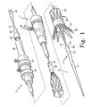
- Figure 1 shows an endovascular delivery device which can be used for delivering and deploying a prosthesis 20 in a lumen of a patient.
- the delivery device includes an external manipulation section 1, a proximal positioning mechanism or attachment region 2, and a distal positioning mechanism or attachment region 3.
- the external manipulation section 1 which is acted upon by a user to manipulate the delivery device, remains outside of the patient throughout the procedure.
- the prosthesis 20 can include a tubular graft material, such as Dacron, with self-expanding stents 19 attached thereto.
- the self-expanding stents 19 cause the prosthesis 20 to expand when released from the delivery device.
- the self-expanding stents 19 may be disposed on the interior surface of the tubular graft material. Alternately, the stents 19 may be disposed on the exterior surface of the tubular graft material.
- the prosthesis 20 also includes an exposed self-expanding zigzag stent 21, which is a bare wire stent.
- the self-expanding stent 21 may have barbs 26 that extend from the stent distal end.
- Self-expanding stents 19, 21 are generally made of metal.
- self-expanding stents 19, 21 may comprise stainless steel, nitinol, or the like.
- a sheath 30 retains the prosthesis 20 in a compressed condition on the delivery device.
- the sheath 30 comprises a generally elongate tubular body.
- the prosthesis 20 is disposed within the sheath lumen.
- the prosthesis 20 and the self-expanding stents 19 radially expand against the inner surface of the sheath 30.
- the sheath 30 preferably comprises a flexible material so that in use it is able to negotiate tortuous inner body lumina.
- the sheath 30 may also include a lubricious or slippery material to facilitate insertion and withdrawal of the thick walled tube 41 and of catheters and the like therethrough.
- the sheath 30 may comprise a plastic material, such as polytetrafluoroethylene (PTFE), polyethylene, nylon, or the like.
- PTFE polytetrafluoroethylene
- the sheath 30 radially compresses the prosthesis 20 over a distal portion of a thin walled tube 15.
- the thin walled tube 15 is generally flexible and may be made of metal, for example stainless steel or nitinol.
- a tube 41 which can be made of plastic, is coaxial with and radially outside the thin walled tube 15. The distal end of the tube 41 is adjacent the proximal end of the prosthesis 20.
- the tube 41 is "thick walled", which is to say the thickness of the wall of tube 41 is several times that of the thin walled tube 15. Preferably, the tube 41 is five or more times thicker than the thin walled tube 15.
- the sheath 30 is coaxial with and radially outside the thick walled tube 41.
- the thick walled tube 41 and the sheath 30 extend proximally to the manipulation region 1, as shown in FIG 5 .
- the thin walled tube 15 extends proximally to the proximal end of the delivery device, as shown in FIG 7 .
- the delivery device further includes haemostatic sealing means 35 radially disposed about the sheath and the thick walled tube 41, as shown in FIG 5 .
- the haemostatic sealing means 35 controls the loss of blood through the delivery device during a procedure.
- FIG 2 illustrates a proximal prosthesis retention and release mechanism.
- the proximal retention section 40 radially and axially retains a proximal end of the prosthesis 20 during the procedure.
- the proximal retention section 40 may comprise the thick walled tube 41, as shown in FIG 2 .
- the proximal retention section 40 may comprise a separate body coupled to the thick walled tube 41.
- the proximal end of the prosthesis 20 comprises an aperture defining a loop 43.
- a proximal trigger wire 44 extends through the loop 43 and through an aperture 45 in the proximal attachment section 40 into an annular region between the thin walled tube 1 5 and the thick walled tube 41.
- the proximal trigger wire 44 extends proximally through the delivery device from the proximal retention section 40 to the release wire actuation section located in the external manipulation section 1 (see FIG 1 ).
- the trigger wire 44 couples the proximal end of the prosthesis 20 to the proximal retention section 40 during deployment to limit axial and radial displacement of the prosthesis.
- the prosthesis 20 can be selectively released into the body lumen by disengaging the trigger wire 44 from the loop 43.
- FIG. 3 illustrates a distal retention and release mechanism.
- the distal attachment region 3 includes a retention device 10.
- the retention device 10 radially and axially retains the distal end of the self-expanding zigzag stent 21 during a procedure.
- the retention device 10 comprises a cover 75. A distal portion of the self-expanding zigzag stent 21 is compressed within the cover 75.
- the retention device 10 may comprise suture loops 66 and a distal trigger wire 22 for coupling the stent 21 to the cover 75 to prevent inadvertent early deployment.
- the retention device 10 has at its distal end a long tapered flexible extension 11, as shown in FIG 3 .
- the flexible extension 11 includes an internal longitudinal aperture 12.
- the longitudinal aperture 12 facilitates advancement of the tapered flexible extension 11 along a previously inserted insertion wire 13.
- the longitudinal aperture 12 also provides a channel for the introduction of medical reagents. For example, it may be desirable to supply a contrast agent to allow angiography to be performed during placement and deployment phases of the medical procedure.
- the distal end of the thin walled tube 15 is coupled to the flexible extension 11.
- the thin walled tube 1 5 is flexible so that the delivery device can be advanced within a relatively tortuous vessel, such as a femoral artery.
- the thin walled tube extends proximally through the delivery device to the manipulation section 1, terminating at a connection means 16, as shown in FIG 7 .
- the thin walled tube 1 5 is in mechanical communication with the flexible extension, allowing the operator axially and rotationally to manipulate the distal attachment region 3 with respect to the prosthesis 20.
- the connection means 16 is adapted to accept a syringe to facilitate the introduction of reagents into the thin walled tube 15.
- the thin walled tube 15 is in fluid communication with the aperture 12 of the flexible extension 11. Therefore, reagents introduced into connection means 1 6 may pass through aperture 1 2 and can emanate from lateral apertures 14 into the body lumen.
- Figure 4B is a plan view of the retention device 10 showing the prosthesis 20 partially deployed, with the self-expanding zigzag stent 21 still retained in a compressed state.
- the distal retention device 10 includes apertures 62 and 64 to accommodate the distal trigger wire 22.
- the suture loops 66 are coupled to the body of the prosthesis 20, and hold the self-expanding zigzag stent 21 in the retention device 10 until the trigger wire 22 is removed. While the trigger wire 22 is in place, the suture loops 66 prevent the retention device 10 and the prosthesis 20 from separating.
- the trigger wire 22 retains the suture loops 66 against an outer surface of the retention device 10.
- the distal trigger wire 22 extends proximally through the delivery device from the distal retention device 10 to a release wire actuation section located in the manipulation section 1 (see FIG 1 ).
- the suture loops 66 are attached to opposing sides of the prosthesis 20, for example separated by 90 to 180 degrees.
- the suture loops 66 are generally inelastic and do not stretch. Since the suture loops 66 do not stretch, they provide opposing torques, thereby preventing the prosthesis 20 from rotating within the retention device 10.
- This configuration differs from delivery devices that have a single point of attachment. Such devices may allow the stent to rotate within the retention device and lead to entanglement of the stent's struts.
- the suture loops 66 are free to move.
- the retention device 10 may then be released from the self-expanding zigzag stent 21 by sliding the retention device 10 distally away from the prosthesis 20.
- the cover 75 includes an opening that extends longitudinally to form a cavity 70, as shown in FIG 4A .
- the cavity 70 may have a generally tubular shape, or it may comprise a generally conical or frustoconical shape, as shown in FIG 4A .
- the cavity 70 shown in FIG 4A decreases linearly in diameter from a maximum diameter A near the proximal opening to a minimum diameter B near the distal end.
- the cavity 70 may alternately decrease non-linearly in diameter.
- the cavity may have a generally arcuate shape.
- the maximum diameter A is between about 5% and about 20% greater than the minimum diameter B.
- the tapered contour of the cavity 70 forces the struts of the self-expanding stent 21 closer together, and decreases the amount of free space in the cavity 70. At the same time, the tapered contour forces the struts of the stent 21 harder against the inner surface 76 of the cover 75, resulting in increased frictional contact therebetween.
- the cover 75 may comprise any suitable biocompatible material.
- the cover 75 may comprise plastic, such as PTFE, polyethylene, nylon, or the like.
- the cover 75 preferably comprises a material that is sufficiently flexible so that the delivery device can negotiate and track tortuous body lumina.
- the cover 75 includes a first surface 76 that forms the cavity 70.
- the cover 75 comprises a material that has a hardness that is equal to or greater than the hardness of the material from which the stent 21 is made.
- the stent 21 may be made of a metal such as 304L stainless steel, nitinol, or the like and may have a hardness that exceeds 30 Rockwell C.
- the first surface 76 has a hardness that is at least as great as the hardness of the material from which the stent is made and may exceed 30 Rockwell C. Any suitable stent material may be used, including materials having a hardness that is less than or greater than 30 Rockwell C. Accordingly, the first surface 76 may have a hardness that is less than or greater than 30 Rockwell C.
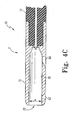
- FIG. 4C illustrates a retention device 10.
- the retention device 10 comprises a cover 75 that is adapted to retain a self-expanding stent 21 in a compressed configuration.
- the cavity 70 decreases in diameter from a maximum diameter A near the distal opening to a minimum diameter B near the proximal end.
- the retention device 10 is threadedly connected to the flexible extension 11.
- the first surface 76 has a hardness that is equal to or greater than the hardness of the material from which the stent 21 is made.
- the cover 75 may be made of commercially pure aluminium or an aluminium alloy.
- Commercially available grades of wrought aluminium alloys that would be suitable include, but are not limited to 1 XXX, 2XXX, 3XXX, 4XXX, 5XXX, 6XXX, 7XXX, and 8XXX series aluminium alloys.
- Commercially available tempers that would be suitable include, but are not limited to T4, T6XXX, T7XXX, T8XXX, T9, and W.
- the aluminium or aluminium alloy may be treated after precipitation or age-hardening by a secondary process to provide the desirable material properties for the first surface 76.
- An example of a suitable secondary treatment process includes hard coat anodizing.
- Hard coat anodizing is a process that is well known in the art of metallurgy.
- a metal substrate is configured as a cathode in an electrochemical cell comprising a sulphuric acid solution.
- the anodizing process forms a ceramic metal oxide layer on the surface of the metal substrate.
- Hard coat anodizing can result in improved surface properties that include increased hardness and improved corrosion resistance. For example, anodized aluminium may have a surface hardness exceeding 60 Rockwell C. Additionally, hard coat anodizing may provide the metal substrate with a smoother, more lubricious surface.
- a suitable treatment process includes hard coat anodizing with PTFE impregnation.
- the process is generally similar to conventional hard coat anodizing.
- the process differs in that the acid solution comprises a PTFE dispersion.
- the metal substrate forms a surface layer comprising PTFE particles impregnated in a metal oxide lattice and is smoother and more lubricious than a surface layer formed by conventional hard coat anodizing.
- PTFE hard-coat anodizing processes include Nituff ® , developed by Nimet Industries and Hardtuf ® , developed by Tiodize Co., Inc.
- the cover 75 may comprise other metals, metal alloys, and/or ceramic,
- the cover 75 may comprise any metal or metal alloy that can be anodized. Examples include, but are not limited to titanium and magnesium. Each of these materials may be anodized to form a hard metal oxide surface layer.
- the cover 75 may comprise stainless steel, for example a martensitic grade such as 440A, 440B, or 440C, or a precipitation-hardenable grade such as 17-4 or 17-7. Suitable secondary treatment processes for stainless steel include carburizing, carbonitriding, nitriding, ferritic carbonitriding, and the like. Each of these processes is well known in the art of metallurgy.
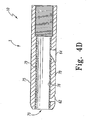
- Figure 4D shows a retention device 10 according to another embodiment.
- the cover 75 is adapted to retain a self-expanding stent 21 therein.
- the first surface 76 has a hardness that is equal to or greater than the hardness of the material from which the stent 21 is made.
- the cover 75 comprises an outer portion 78 and an inner portion 79.
- the outer portion 78 comprises a different material than the inner portion 79.
- the inner portion 79 defines the first surface 76.
- the outer portion 78 may comprise a low-durometer plastic, for example nylon, having a relatively low hardness. Such a material may be desirable for imparting flexibility to the delivery device.
- the inner portion 79 comprises a material that is selected so that the first surface 76 has a hardness that is equal to or greater than the hardness of the material from which the stent 21 that is used in the particular application is made.
- the inner portion 79 may comprise a metal, metal alloy, or ceramic material as described above.
- the inner portion 79 may be treated using a secondary process to provide the first surface 76 with desirable surface properties, as described above.
- the retention device 10 is coupled to the flexible extension 11.
- the retention device 10 may be threadedly attached to the extension 11 (as shown in FIG 4D ).
- the retention device 10 and the flexible extension 11 may be adhesively bonded or mechanically coupled to one another.
- the retention device 10 comprises plastic
- the retention device 10 and the flexible extension may be thermally bonded to one another.
- the cover 75 illustrated in FIG 4D may be manufactured by any suitable process.
- the outer portion 78 may comprise plastic and may be provided by a suitable process such as injection moulding.
- the inner portion 79 may be applied to a cavity within the outer portion 78 as a metallized coating that provides the first surface 76.
- the metallized coating may be applied using a conventional spray or dip application process. Examples of suitable metallizing materials include, but are not limited to hard chromium, electroless nickel, brass, or copper alloys.
- Another manufacturing method may include providing a plastic outer portion 78 as described above.
- the inner portion 79 may comprise a generally tubular bushing.
- the bushing may be inserted into a cavity within the outer portion 78.
- the bushing is fixedly attached to the outer portion 78 using conventional means, including adhesive bonding or press-fitting.
- the tubular bushing has a lumen that defines the first surface 76 of the cover 75.
- the bushing may be made of any suitable biocompatible material that has a hardness that is equal to or greater than the hardness of the material from which the stent 21 is made.
- the bushing may comprise an anodized metal or a hardened alloy steel such as 52100 steel.
- the bushing may alternately comprise a carbon or low alloy steel that has been treated by nitriding, ferritic carbonitriding, carbonitriding, or a like process.
- the first surface 76 may be formed in many different ways. For example, it may be formed from the same material as the cover 75, it may be formed by treating the material from which the cover 75 is formed, it may be formed by coating at least a portion of the cover 75 or by providing a separate layer 79 or bushing (which may or may not itself be treated).
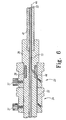
- FIG. 5 shows the haemostatic sealing means 35 of the external manipulation section 1 in greater detail.
- the haemostatic sealing means 35 comprises a haemostatic seal 27 and a clamping collar 23 that clamps the sheath 30 to the haemostatic seal 27.
- the haemostatic seal 27 may include a silicone seal ring 28.
- the silicone seal ring 28 forms a haemostatic seal around the thick walled tube 41.
- the haemostatic sealing means 35 may include a side tube 29.
- the side tube 29 facilitates the introduction of medical reagents between the thick walled tube 41 and the sheath 30.
- the distal trigger wire 22 extends through the annular space between the thick walled tube 41 and the thin walled tube 15 to the manipulation region 1.
- the distal trigger wire 22 exits the annular space at a distal wire release mechanism 24.
- the self-expanding stent 21 is released by retracting the sheath 30, removing the trigger wire 22, and then sliding the distal attachment region 3, including the retention device 10, distally away from the stent 21. Once the retention device 10 has cleared the self-expanding stent 21 , the stent 21 will expand.
- the suture loops 66, the trigger wire 22, and the distal wire release mechanism 24 form a control member to selectively release the retention device 10 from the prosthesis 20 by holding the self-expanding stent 21 in the retention device 10 until the prosthesis 20 is positioned at a desired site in the lumen.
- the proximal trigger wire 44 extends through the annular space between the thick walled tube 41 and the thin walled tube 15 to the manipulation region.
- the proximal trigger wire 44 exits the annular space at a proximal wire release mechanism 25.
- the proximal trigger wire 44 and the proximal wire release mechanism 25 form a control member for selectively releasing the proximal retention section 40 from the prosthesis when the prosthesis is positioned at a desired site in the lumen.
- the release wire actuation section has a body 36 that is mounted onto the thick walled plastic tube 41, as shown in FIG 6 .
- the thin walled tube 15 passes through the body 36.
- the proximal wire release mechanism 25 is mounted for slidable movement on the body 36.
- a clamping screw 37 prevents inadvertent early release of the proximal end 42 of the prosthesis 20.
- the distal wire release mechanism 24 is mounted for slidable movement on the body 36.
- a clamping screw 37 prevents inadvertent early release of the self-expanding zigzag stent 21 of the prosthesis 20.
- the positioning of the distal and proximal wire release mechanisms 24 and 25 is such that the distal wire release mechanism 24 must be moved before the proximal wire release mechanism 25 can be moved. Therefore, the proximal end of the prosthesis 20 cannot be released until the self-expanding zigzag stent 21 has been released and anchored to the lumen.
- a haemostatic seal 38 is provided so the release wire 44 can extend out through the body 36 to the release mechanism 25 without unnecessary blood loss during the medical procedure.
- Figure 7 shows a proximal portion of the external manipulation section 1.
- a pin vice 39 is mounted onto the proximal end of the body 38.
- the pin vice has a screw cap 46.
- the vice jaws 47 clamp against (engage) the thin walled metal tube 15.
- the vice jaws 47 are engaged, the thin walled tube 15 can only move with the body 36, and hence the thin walled tube 15 can only move with the thick walled tube 41 (not shown).
- the screw cap 46 tightened, the entire assembly, except for the external sleeve 30, can be moved as one.
- a guide wire 13 is introduced, for example, into the femoral artery and is advanced until the tip of the guide wire 13 is beyond the region into which the prosthesis 20 is to be deployed.
- the delivery device is then inserted through the femoral artery over the guide wire 13, and positioned by radiographic techniques, generally known in the art.
- the ends of the prosthesis 20 are retained by the distal and proximal retaining assemblies respectively and the sheath 30 is disposed over and covers the length of the prosthesis 20.
- the self-expanding stent 21 is compressed within the cover 75.
- the delivery device is shown fully assembled ready for introduction into a patient.
- the ends of the prosthesis 20 are retained by the distal and proximal retaining assemblies respectively, while the sheath 30 compresses the middle portion of the prosthesis intermediate the ends.
- the sheath 30 can be withdrawn to just distal of the proximal attachment section 40, as shown in FIG 9 .
- This action exposes the middle portion of the prosthesis 20 so that the middle portion can expand radially outwardly.
- the self-expanding stent 21 is still retained within the cover 75 of the retention device 10.
- the proximal end of the prosthesis 20 is still retained within the sheath 30.
- the pin vice 39 is released to allow small movements of the thin walled tubing 15 with respect to the thick walled tubing.
- the prosthesis 20 may be lengthened or shortened or rotated or compressed for accurate placement in the desired location within the lumen.
- X-ray opaque markers may be placed along the prosthesis 20 to assist with placement of the prosthesis.
- the distal trigger wire 22 has been removed, allowing the cover 75 to be separated from the self-expanding zigzag stent 21, as explained above.
- the distal trigger wire release mechanism 24 and the distal trigger wire 22 can be removed completely.
- the screw cap 46 of the pin vice 39 has been loosened so that the thin walled tubing 15 can be pushed in a distal direction to move the cover 75 in a distal direction with respect to the stent 21.
- the cover 75 no longer surrounds the self-expanding stent 21 at the distal end of the prosthesis 20, the self-expanding stent 21 expands.
- the barbs 26 grip into the walls of the lumen to hold the proximal end of the prosthesis 20 in place.
- the proximal end of the prosthesis 20 is still retained by the proximal retention section 40 with the loop 43 retained therein.
- the sheath 30 is then withdrawn to proximal of the proximal retention section 40 to allow the proximal end of the prosthesis 20 to expand.
- the proximal end of the prosthesis may still be moved. Consequently, the prosthesis 20 can still be rotated or lengthened or shortened or otherwise moved for accurate positioning.
- the movement at this stage may ensure that the shorter leg is directed in the direction of the contra-iliac artery.
- the proximal end 42 of the prosthesis 20 has been released by the removal of the proximal trigger wire 44.
- the proximal trigger wire release mechanism 25 and the proximal trigger wire 44 can be removed completely. This removal may be accomplished by passing the proximal wire release mechanism 25 over the pin vice 39 and the connection means 16.
- the loop 43 of the terminal proximal self-expanding zigzag stent 19 is hence released, and the prosthesis is now free to expand to the walls of the vessel.
- the delivery device is ready to be removed.
- the sheath 30 may be removed with the distal attachment device 10, the tapered flexible extension 11 and the proximal attachment device 10. Alternatively, these items could be removed separately, followed by removal of the external sleeve 30.
Abstract
Description
- This application relates to delivery of an endoluminal prosthesis. In particular it relates to apparatus for endoluminally delivering and deploying a prosthesis; a method of manufacturing an endoluminal prosthesis delivery and deployment apparatus, a cover for maintaining a self-expanding stent in a compressed configuration, and a delivery device for endoluminally delivering and deploying a prosthesis.
- The deployment of endoluminal prostheses into the lumen of a patient from a remote location by the use of a deployment device is generally known. An endoluminal prosthesis may be retained in a radially constrained state within a sleeve until it is deployed. To deploy the prosthesis, the sleeve is withdrawn from the prosthesis allowing the prosthesis to expand. The prosthesis may be radially self-expanding or it may be balloon expandable. The prosthesis may comprise a graft and/or a stent.
-
US 2004/0098079 ,US 2004/0106974 ,US 2005/0085890 andUS 2005/0060018 , disclose various delivery devices for an expandable endoluminal prosthesis. The expandable endovascular prosthesis comprises a bare self-expanding stent disposed on an end portion thereof. The self-expanding stent may comprise a plurality of barbs that in use are adapted to anchor the prosthesis to a surrounding body lumen. A cover retains an end portion of the self-expanding stent on the delivery device in a radially constrained state. To deploy the prosthesis, the operator withdraws the cover from the self-expanding stent, thereby exposing the stent and allowing it to expand radially outwardly. - The stent radially expands against an inner surface of the cover prior to deployment. The expansion force of the stent against the inner surface can be sufficiently high so as to create significant interference between the stent and the cover. This can result in increased operating effort to remove the cover from the stent. This is particularly true where the stent comprises sharpened barbs that may scratch or dig into the inner surface of the cover.
-
WO 03/005936 - According to a first aspect of the present invention, there is provided a delivery device for endoluminally delivering and deploying a prosthesis as specified in claim 1.
- Accordingly, the stent cannot dig into the cover and the operating effort to remove the cover from the prosthesis is reduced.
- Preferably the outer portion includes a plastic and/or the inner portion includes a metal, a metal alloy or a ceramic material.
- The stent may be made from any suitable material, such as stainless steel or nitinol. The first surface of the cover may include a metal, a metal alloy, or a ceramic. In a preferred embodiment, the first surface comprises anodized aluminium and may optionally comprise PTFE. The cover may comprise a plastic body with a metal first surface.
- The stent may include a plurality of radially-disposed barbs for anchoring the stent within the lumen. The barbs engage the first surface of the cover until deployment. Because the first surface is generally as hard, or harder than the stent, a particularly aggressive stent or barb design may be used in conjunction with the cover. At least a portion of the prosthesis may be radially disposed within the lumen of a sheath in a compressed configuration.
- According to a second aspect of the present invention, there is provided a method of manufacturing an endoluminal prosthesis delivery and deployment apparatus as specified in
claim 10. - The stent and the cover may include any suitable material, as described above. For example, the stent may include stainless steel and the first surface of the cover may be made of anodized aluminium and PTFE.
- The cover providing step may include inserting a metal bushing into the cavity so that an inner lumen of the bushing provides the first surface of the cover. The cover providing step may include applying a metallized coating to the cover to form the first surface.
- Preferred embodiments of the present invention and further examples are described below, by way of example only, with reference to the accompanying drawings, in which:
-
FIG 1 is a perspective view of a delivery device according to an embodiment; -
FIG 2 is a sectional detail view of a portion of the delivery device ofFIG 1 around the proximal end of the prosthesis; -
FIG 3 is a sectional detail view of a portion of the delivery device ofFIG 1 around the distal end of the prosthesis; -
FIG 4A is a sectional view of a distal retention device of the delivery device ofFIG 1 ; -
FIG 4B is a plan view of the distal retention device of the delivery device ofFIG 1 ; -
FIG 4C is a sectional view of distal retention device according to an embodiment; -
FIG 4D is a sectional view of a distal retention device according to an embodiment; -
FIG 5 is a sectional view of a portion of the delivery device ofFIG 1 around the haemostatic seal; -
FIG 6 is a sectional view of a portion of the delivery device ofFIG 1 around the trigger wire release mechanism; -
FIG 7 is a sectional view of a portion of the delivery device ofFIG 1 around the pin vise clamp and the medical reagent introduction tube; -
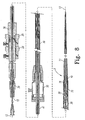
FIG 8 is a segmented sectional view of the delivery device ofFIG 1 , fully loaded and ready for introduction into a patient; -
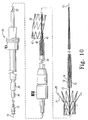
FIG 9 is a segmented sectional view of the delivery device ofFIG 1 , demonstrating the prosthesis in an initial stage of deployment; -
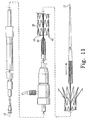
FIG 10 is a segmented sectional view of the delivery device ofFIG 1 , demonstrating the release of the prosthesis distal end during deployment; and -
FIG 11 is a segmented sectional view of the delivery device ofFIG 1 , demonstrating the release of the prosthesis proximal end during deployment. - Throughout the specification, the terms "distal" and "distally" shall denote a position, direction, or orientation that is generally toward the patient. Accordingly, the terms "proximal" and "proximally" shall denote a position, direction, or orientation that is generally away from the patient.
-
Figure 1 shows an endovascular delivery device which can be used for delivering and deploying aprosthesis 20 in a lumen of a patient. The delivery device includes an external manipulation section 1, a proximal positioning mechanism orattachment region 2, and a distal positioning mechanism orattachment region 3. During a medical procedure to deploy theprosthesis 20, the proximal anddistal attachment regions - The
prosthesis 20 can include a tubular graft material, such as Dacron, with self-expandingstents 19 attached thereto. The self-expandingstents 19 cause theprosthesis 20 to expand when released from the delivery device. The self-expandingstents 19 may be disposed on the interior surface of the tubular graft material. Alternately, thestents 19 may be disposed on the exterior surface of the tubular graft material. Theprosthesis 20 also includes an exposed self-expandingzigzag stent 21, which is a bare wire stent. The self-expandingstent 21 may havebarbs 26 that extend from the stent distal end. When the self-expandingstent 21 is released, thebarbs 26 anchor the distal end of theprosthesis 20 to the surrounding lumen (not shown). Self-expandingstents stents - A
sheath 30 retains theprosthesis 20 in a compressed condition on the delivery device. Thesheath 30 comprises a generally elongate tubular body. Theprosthesis 20 is disposed within the sheath lumen. Theprosthesis 20 and the self-expandingstents 19 radially expand against the inner surface of thesheath 30. Thesheath 30 preferably comprises a flexible material so that in use it is able to negotiate tortuous inner body lumina. Thesheath 30 may also include a lubricious or slippery material to facilitate insertion and withdrawal of the thickwalled tube 41 and of catheters and the like therethrough. Accordingly, thesheath 30 may comprise a plastic material, such as polytetrafluoroethylene (PTFE), polyethylene, nylon, or the like. - The
sheath 30 radially compresses theprosthesis 20 over a distal portion of a thinwalled tube 15. The thinwalled tube 15 is generally flexible and may be made of metal, for example stainless steel or nitinol. Atube 41, which can be made of plastic, is coaxial with and radially outside the thinwalled tube 15. The distal end of thetube 41 is adjacent the proximal end of theprosthesis 20. - The
tube 41 is "thick walled", which is to say the thickness of the wall oftube 41 is several times that of the thinwalled tube 15. Preferably, thetube 41 is five or more times thicker than the thinwalled tube 15. Thesheath 30 is coaxial with and radially outside the thickwalled tube 41. The thickwalled tube 41 and thesheath 30 extend proximally to the manipulation region 1, as shown inFIG 5 . The thinwalled tube 15 extends proximally to the proximal end of the delivery device, as shown inFIG 7 . The delivery device further includes haemostatic sealing means 35 radially disposed about the sheath and the thickwalled tube 41, as shown inFIG 5 . The haemostatic sealing means 35 controls the loss of blood through the delivery device during a procedure. -
Figure 2 illustrates a proximal prosthesis retention and release mechanism. Theproximal retention section 40 radially and axially retains a proximal end of theprosthesis 20 during the procedure. Theproximal retention section 40 may comprise the thickwalled tube 41, as shown inFIG 2 . Alternately, theproximal retention section 40 may comprise a separate body coupled to the thickwalled tube 41. The proximal end of theprosthesis 20 comprises an aperture defining aloop 43. Aproximal trigger wire 44 extends through theloop 43 and through anaperture 45 in theproximal attachment section 40 into an annular region between the thin walled tube 1 5 and the thickwalled tube 41. Theproximal trigger wire 44 extends proximally through the delivery device from theproximal retention section 40 to the release wire actuation section located in the external manipulation section 1 (seeFIG 1 ). Thetrigger wire 44 couples the proximal end of theprosthesis 20 to theproximal retention section 40 during deployment to limit axial and radial displacement of the prosthesis. Theprosthesis 20 can be selectively released into the body lumen by disengaging thetrigger wire 44 from theloop 43. -
Figure 3 illustrates a distal retention and release mechanism. Thedistal attachment region 3 includes aretention device 10. Theretention device 10 radially and axially retains the distal end of the self-expandingzigzag stent 21 during a procedure. Theretention device 10 comprises acover 75. A distal portion of the self-expandingzigzag stent 21 is compressed within thecover 75. Theretention device 10 may comprisesuture loops 66 and adistal trigger wire 22 for coupling thestent 21 to thecover 75 to prevent inadvertent early deployment. - The
retention device 10 has at its distal end a long taperedflexible extension 11, as shown inFIG 3 . Theflexible extension 11 includes an internal longitudinal aperture 12. The longitudinal aperture 12 facilitates advancement of the taperedflexible extension 11 along a previously insertedinsertion wire 13. The longitudinal aperture 12 also provides a channel for the introduction of medical reagents. For example, it may be desirable to supply a contrast agent to allow angiography to be performed during placement and deployment phases of the medical procedure. - The distal end of the thin
walled tube 15 is coupled to theflexible extension 11. The thin walled tube 1 5 is flexible so that the delivery device can be advanced within a relatively tortuous vessel, such as a femoral artery. The thin walled tube extends proximally through the delivery device to the manipulation section 1, terminating at a connection means 16, as shown inFIG 7 . The thin walled tube 1 5 is in mechanical communication with the flexible extension, allowing the operator axially and rotationally to manipulate thedistal attachment region 3 with respect to theprosthesis 20. The connection means 16 is adapted to accept a syringe to facilitate the introduction of reagents into the thinwalled tube 15. The thinwalled tube 15 is in fluid communication with the aperture 12 of theflexible extension 11. Therefore, reagents introduced into connection means 1 6 may pass through aperture 1 2 and can emanate fromlateral apertures 14 into the body lumen. -
Figure 4B is a plan view of theretention device 10 showing theprosthesis 20 partially deployed, with the self-expandingzigzag stent 21 still retained in a compressed state. Thedistal retention device 10 includesapertures distal trigger wire 22. Thesuture loops 66 are coupled to the body of theprosthesis 20, and hold the self-expandingzigzag stent 21 in theretention device 10 until thetrigger wire 22 is removed. While thetrigger wire 22 is in place, thesuture loops 66 prevent theretention device 10 and theprosthesis 20 from separating. Thetrigger wire 22 retains thesuture loops 66 against an outer surface of theretention device 10. Thedistal trigger wire 22 extends proximally through the delivery device from thedistal retention device 10 to a release wire actuation section located in the manipulation section 1 (seeFIG 1 ). - As shown in
FIG 4B , thesuture loops 66 are attached to opposing sides of theprosthesis 20, for example separated by 90 to 180 degrees. Thesuture loops 66 are generally inelastic and do not stretch. Since thesuture loops 66 do not stretch, they provide opposing torques, thereby preventing theprosthesis 20 from rotating within theretention device 10. This configuration differs from delivery devices that have a single point of attachment. Such devices may allow the stent to rotate within the retention device and lead to entanglement of the stent's struts. When thetrigger wire 22 is removed, thesuture loops 66 are free to move. Theretention device 10 may then be released from the self-expandingzigzag stent 21 by sliding theretention device 10 distally away from theprosthesis 20. - The
cover 75 includes an opening that extends longitudinally to form acavity 70, as shown inFIG 4A . Thecavity 70 may have a generally tubular shape, or it may comprise a generally conical or frustoconical shape, as shown inFIG 4A . Thecavity 70 shown inFIG 4A decreases linearly in diameter from a maximum diameter A near the proximal opening to a minimum diameter B near the distal end. Thecavity 70 may alternately decrease non-linearly in diameter. For example, the cavity may have a generally arcuate shape. In an embodiment, the maximum diameter A is between about 5% and about 20% greater than the minimum diameter B. The tapered contour of thecavity 70 forces the struts of the self-expandingstent 21 closer together, and decreases the amount of free space in thecavity 70. At the same time, the tapered contour forces the struts of thestent 21 harder against theinner surface 76 of thecover 75, resulting in increased frictional contact therebetween. - The
cover 75 may comprise any suitable biocompatible material. For example, thecover 75 may comprise plastic, such as PTFE, polyethylene, nylon, or the like. Thecover 75 preferably comprises a material that is sufficiently flexible so that the delivery device can negotiate and track tortuous body lumina. - In the preferred embodiment the
cover 75 includes afirst surface 76 that forms thecavity 70. Thecover 75 comprises a material that has a hardness that is equal to or greater than the hardness of the material from which thestent 21 is made. Thestent 21 may be made of a metal such as 304L stainless steel, nitinol, or the like and may have a hardness that exceeds 30 Rockwell C. Accordingly thefirst surface 76 has a hardness that is at least as great as the hardness of the material from which the stent is made and may exceed 30 Rockwell C. Any suitable stent material may be used, including materials having a hardness that is less than or greater than 30 Rockwell C. Accordingly, thefirst surface 76 may have a hardness that is less than or greater than 30 Rockwell C. -
Figure 4C illustrates aretention device 10. Theretention device 10 comprises acover 75 that is adapted to retain a self-expandingstent 21 in a compressed configuration. Thecavity 70 decreases in diameter from a maximum diameter A near the distal opening to a minimum diameter B near the proximal end. Theretention device 10 is threadedly connected to theflexible extension 11. - The
first surface 76 has a hardness that is equal to or greater than the hardness of the material from which thestent 21 is made. Thecover 75 may be made of commercially pure aluminium or an aluminium alloy. Commercially available grades of wrought aluminium alloys that would be suitable include, but are not limited to 1 XXX, 2XXX, 3XXX, 4XXX, 5XXX, 6XXX, 7XXX, and 8XXX series aluminium alloys. Commercially available tempers that would be suitable include, but are not limited to T4, T6XXX, T7XXX, T8XXX, T9, and W. The aluminium or aluminium alloy may be treated after precipitation or age-hardening by a secondary process to provide the desirable material properties for thefirst surface 76. - An example of a suitable secondary treatment process includes hard coat anodizing. Hard coat anodizing is a process that is well known in the art of metallurgy. A metal substrate is configured as a cathode in an electrochemical cell comprising a sulphuric acid solution. The anodizing process forms a ceramic metal oxide layer on the surface of the metal substrate. Hard coat anodizing can result in improved surface properties that include increased hardness and improved corrosion resistance. For example, anodized aluminium may have a surface hardness exceeding 60 Rockwell C. Additionally, hard coat anodizing may provide the metal substrate with a smoother, more lubricious surface.
- Another example of a suitable treatment process includes hard coat anodizing with PTFE impregnation. The process is generally similar to conventional hard coat anodizing. The process differs in that the acid solution comprises a PTFE dispersion. The metal substrate forms a surface layer comprising PTFE particles impregnated in a metal oxide lattice and is smoother and more lubricious than a surface layer formed by conventional hard coat anodizing. Examples of PTFE hard-coat anodizing processes include Nituff®, developed by Nimet Industries and Hardtuf®, developed by Tiodize Co., Inc.
- The
cover 75 may comprise other metals, metal alloys, and/or ceramic, For example, thecover 75 may comprise any metal or metal alloy that can be anodized. Examples include, but are not limited to titanium and magnesium. Each of these materials may be anodized to form a hard metal oxide surface layer. Alternately, thecover 75 may comprise stainless steel, for example a martensitic grade such as 440A, 440B, or 440C, or a precipitation-hardenable grade such as 17-4 or 17-7. Suitable secondary treatment processes for stainless steel include carburizing, carbonitriding, nitriding, ferritic carbonitriding, and the like. Each of these processes is well known in the art of metallurgy. -
Figure 4D shows aretention device 10 according to another embodiment. Thecover 75 is adapted to retain a self-expandingstent 21 therein. Thefirst surface 76 has a hardness that is equal to or greater than the hardness of the material from which thestent 21 is made. - As shown in
FIG 4D , thecover 75 comprises anouter portion 78 and an inner portion 79. Theouter portion 78 comprises a different material than the inner portion 79. The inner portion 79 defines thefirst surface 76. Theouter portion 78 may comprise a low-durometer plastic, for example nylon, having a relatively low hardness. Such a material may be desirable for imparting flexibility to the delivery device. The inner portion 79, on the other hand comprises a material that is selected so that thefirst surface 76 has a hardness that is equal to or greater than the hardness of the material from which thestent 21 that is used in the particular application is made. For example, the inner portion 79 may comprise a metal, metal alloy, or ceramic material as described above. The inner portion 79 may be treated using a secondary process to provide thefirst surface 76 with desirable surface properties, as described above. - The
retention device 10 is coupled to theflexible extension 11. Theretention device 10 may be threadedly attached to the extension 11 (as shown inFIG 4D ). Alternately, theretention device 10 and theflexible extension 11 may be adhesively bonded or mechanically coupled to one another. For example, if theretention device 10 comprises plastic, theretention device 10 and the flexible extension may be thermally bonded to one another. - The
cover 75 illustrated inFIG 4D may be manufactured by any suitable process. For example, theouter portion 78 may comprise plastic and may be provided by a suitable process such as injection moulding. The inner portion 79 may be applied to a cavity within theouter portion 78 as a metallized coating that provides thefirst surface 76. The metallized coating may be applied using a conventional spray or dip application process. Examples of suitable metallizing materials include, but are not limited to hard chromium, electroless nickel, brass, or copper alloys. - Another manufacturing method may include providing a plastic
outer portion 78 as described above. The inner portion 79 may comprise a generally tubular bushing. The bushing may be inserted into a cavity within theouter portion 78. The bushing is fixedly attached to theouter portion 78 using conventional means, including adhesive bonding or press-fitting. The tubular bushing has a lumen that defines thefirst surface 76 of thecover 75. The bushing may be made of any suitable biocompatible material that has a hardness that is equal to or greater than the hardness of the material from which thestent 21 is made. For example, the bushing may comprise an anodized metal or a hardened alloy steel such as 52100 steel. The bushing may alternately comprise a carbon or low alloy steel that has been treated by nitriding, ferritic carbonitriding, carbonitriding, or a like process. - It can thus be seen that the
first surface 76 may be formed in many different ways. For example, it may be formed from the same material as thecover 75, it may be formed by treating the material from which thecover 75 is formed, it may be formed by coating at least a portion of thecover 75 or by providing a separate layer 79 or bushing (which may or may not itself be treated). -
Figure 5 shows the haemostatic sealing means 35 of the external manipulation section 1 in greater detail. The haemostatic sealing means 35 comprises ahaemostatic seal 27 and aclamping collar 23 that clamps thesheath 30 to thehaemostatic seal 27. Thehaemostatic seal 27 may include asilicone seal ring 28. Thesilicone seal ring 28 forms a haemostatic seal around the thickwalled tube 41. The haemostatic sealing means 35 may include aside tube 29. Theside tube 29 facilitates the introduction of medical reagents between the thickwalled tube 41 and thesheath 30. - As shown in
FIG 6 , thedistal trigger wire 22 extends through the annular space between the thickwalled tube 41 and the thinwalled tube 15 to the manipulation region 1. Thedistal trigger wire 22 exits the annular space at a distalwire release mechanism 24. The self-expandingstent 21 is released by retracting thesheath 30, removing thetrigger wire 22, and then sliding thedistal attachment region 3, including theretention device 10, distally away from thestent 21. Once theretention device 10 has cleared the self-expandingstent 21 , thestent 21 will expand. Thesuture loops 66, thetrigger wire 22, and the distalwire release mechanism 24 form a control member to selectively release theretention device 10 from theprosthesis 20 by holding the self-expandingstent 21 in theretention device 10 until theprosthesis 20 is positioned at a desired site in the lumen. - The
proximal trigger wire 44 extends through the annular space between the thickwalled tube 41 and the thinwalled tube 15 to the manipulation region. Theproximal trigger wire 44 exits the annular space at a proximalwire release mechanism 25. Theproximal trigger wire 44 and the proximalwire release mechanism 25 form a control member for selectively releasing theproximal retention section 40 from the prosthesis when the prosthesis is positioned at a desired site in the lumen. - The release wire actuation section has a
body 36 that is mounted onto the thick walledplastic tube 41, as shown inFIG 6 . The thinwalled tube 15 passes through thebody 36. The proximalwire release mechanism 25 is mounted for slidable movement on thebody 36. A clampingscrew 37 prevents inadvertent early release of theproximal end 42 of theprosthesis 20. Similarly, the distalwire release mechanism 24 is mounted for slidable movement on thebody 36. A clampingscrew 37 prevents inadvertent early release of the self-expandingzigzag stent 21 of theprosthesis 20. - The positioning of the distal and proximal
wire release mechanisms wire release mechanism 24 must be moved before the proximalwire release mechanism 25 can be moved. Therefore, the proximal end of theprosthesis 20 cannot be released until the self-expandingzigzag stent 21 has been released and anchored to the lumen. Ahaemostatic seal 38 is provided so therelease wire 44 can extend out through thebody 36 to therelease mechanism 25 without unnecessary blood loss during the medical procedure. -
Figure 7 shows a proximal portion of the external manipulation section 1. Apin vice 39 is mounted onto the proximal end of thebody 38. The pin vice has ascrew cap 46. When screwed in, the vice jaws 47 clamp against (engage) the thinwalled metal tube 15. When the vice jaws 47 are engaged, the thinwalled tube 15 can only move with thebody 36, and hence the thinwalled tube 15 can only move with the thick walled tube 41 (not shown). With thescrew cap 46 tightened, the entire assembly, except for theexternal sleeve 30, can be moved as one. - The various stages of delivery and deployment of the
prosthesis 20 will now be explained with reference toFIGS 8 to 11 that claimed by the current invention. Aguide wire 13 is introduced, for example, into the femoral artery and is advanced until the tip of theguide wire 13 is beyond the region into which theprosthesis 20 is to be deployed. The delivery device is then inserted through the femoral artery over theguide wire 13, and positioned by radiographic techniques, generally known in the art. At this stage, the ends of theprosthesis 20 are retained by the distal and proximal retaining assemblies respectively and thesheath 30 is disposed over and covers the length of theprosthesis 20. The self-expandingstent 21 is compressed within thecover 75. - In
FIG 8 , the delivery device is shown fully assembled ready for introduction into a patient. The ends of theprosthesis 20 are retained by the distal and proximal retaining assemblies respectively, while thesheath 30 compresses the middle portion of the prosthesis intermediate the ends. Once the delivery device is in a desired position for deployment of theprosthesis 20, thesheath 30 can be withdrawn to just distal of theproximal attachment section 40, as shown inFIG 9 . This action exposes the middle portion of theprosthesis 20 so that the middle portion can expand radially outwardly. The self-expandingstent 21, however, is still retained within thecover 75 of theretention device 10. Also, the proximal end of theprosthesis 20 is still retained within thesheath 30. - Next, the
pin vice 39 is released to allow small movements of the thinwalled tubing 15 with respect to the thick walled tubing. In this way, theprosthesis 20 may be lengthened or shortened or rotated or compressed for accurate placement in the desired location within the lumen. X-ray opaque markers (not shown) may be placed along theprosthesis 20 to assist with placement of the prosthesis. - In
FIG 10 , thedistal trigger wire 22 has been removed, allowing thecover 75 to be separated from the self-expandingzigzag stent 21, as explained above. At this stage, the distal triggerwire release mechanism 24 and thedistal trigger wire 22 can be removed completely. Thescrew cap 46 of thepin vice 39 has been loosened so that the thinwalled tubing 15 can be pushed in a distal direction to move thecover 75 in a distal direction with respect to thestent 21. When thecover 75 no longer surrounds the self-expandingstent 21 at the distal end of theprosthesis 20, the self-expandingstent 21 expands. When the self-expandingstent 21 expands, thebarbs 26 grip into the walls of the lumen to hold the proximal end of theprosthesis 20 in place. - At this point, the proximal end of the
prosthesis 20 is still retained by theproximal retention section 40 with theloop 43 retained therein. Thesheath 30 is then withdrawn to proximal of theproximal retention section 40 to allow the proximal end of theprosthesis 20 to expand. At this point, the proximal end of the prosthesis may still be moved. Consequently, theprosthesis 20 can still be rotated or lengthened or shortened or otherwise moved for accurate positioning. Where theprosthesis 20 to be deployed is a bifurcated graft, the movement at this stage may ensure that the shorter leg is directed in the direction of the contra-iliac artery. - In
FIG 11 , theproximal end 42 of theprosthesis 20 has been released by the removal of theproximal trigger wire 44. At this stage, the proximal triggerwire release mechanism 25 and theproximal trigger wire 44 can be removed completely. This removal may be accomplished by passing the proximalwire release mechanism 25 over thepin vice 39 and the connection means 16. Theloop 43 of the terminal proximal self-expandingzigzag stent 19 is hence released, and the prosthesis is now free to expand to the walls of the vessel. At this point, the delivery device is ready to be removed. Thesheath 30 may be removed with thedistal attachment device 10, the taperedflexible extension 11 and theproximal attachment device 10. Alternatively, these items could be removed separately, followed by removal of theexternal sleeve 30. - Throughout this specification, unless the context requires otherwise, the words "comprise", "include", and "have" and variations such as "comprising", "including", and "having" will be understood to imply the inclusion of an item or group of items, but not the exclusion of any other item or group items.
- While various embodiments of the invention have been described, it will be apparent to those of ordinary skill in the art that many more embodiments and implementations are possible within the scope of the invention. Furthermore, although various indications have been given as to the scope of this invention, the invention is not limited to any one of these but may reside in two or more of these combined together. Accordingly, the invention is not to be restricted except in light of the appended claims.
Claims (15)
- A delivery device for endoluminally delivering and deploying a prosthesis (20) including:a prosthesis (20) including a body portion and an end portion, the end portion including a self-expanding stent (21);a sheath (30) having a sheath lumen, to retain the body portion of the prosthesis (20) in a compressed configuration on the delivery device;a cover (75) for maintaining at least a portion of the self-expanding stent (21) at the end portion of the prosthesis (20) in a compressed state until the deployment;the cover including a cavity (70), wherein in its compressed state the self-expanding stent is located in the cavity, wherein the cover (75) includes an outer portion (78) and an inner portion (79), wherein the outer portion (78) includes a material having a hardness lower than that of the inner portion (79), wherein the inner portion defines a first surface (76) against which a compressed stent (21) may be biased, and wherein the first surface (76) has a hardness that is equal to or greater than the hardness of the stent (21).
- A delivery device as claimed in claim 1, wherein the outer portion (78) includes a plastic material.
- A delivery device as claim in claim 1 or 2, wherein the first surface is an anodized metal or anodized metal alloy.
- A delivery device as claimed in claim 1, 2 or 3, wherein the first surface (76) includes PTFE particles impregnated in a metal oxide lattice.
- A delivery device as claimed in any preceding claim, wherein the first surface is anodized aluminium.
- A device as claimed in claim 1 or 2, wherein the first surface includes stainless steel, wherein the stainless steel has been treated by carburizing, carbonitriding, nitriding, or ferritic carbonitriding.
- A delivery device as claimed in any preceding claim, wherein:the first surface (76) includes metal and/or ceramic;the first surface (76) further includes PTFE; andthe stent (21) comprises a plurality of radially-disposed barbs (26) and is made from stainless steel and/or nitinol.
- A delivery device as claimed in any preceding claim, wherein the cavity (70) has a shape that is generally tubular, generally conical or generally frustoconical.
- A delivery device as claimed in any preceding claim, wherein the stent (21) includes a plurality of radially-disposed barbs (26).
- A method of manufacturing an endoluminal prosthesis delivery and deployment apparatus, the method comprising the steps of:providing a prosthesis (20) provided with a body portion, a proximal end and a distal end, at least one of the proximal and distal ends including a self-expanding stent (21);providing a cover (75) including a cavity (70) and a first surface (76), the first surface having a hardness that is equal to or greater than the hardness of the stent, wherein the cover (75) includes an outer portion (78) and an inner portion (79), wherein the outer portion includes a material having a hardness lower than that of the inner portion (79) and wherein the inner portion defines the first surface (76);retaining at least a portion of the stent (21) within the cavity (70) so that the stent (21) is biased into contact with the first surface (76); andproviding a sheath (30) having a sheath lumen to retain the body portion of the prosthesis (20) in a compressed configuration.
- A method as claimed in claim 10, wherein the cover-providing step includes providing a first surface (76) made of an anodized metal or anodized metal alloy.
- A method as claimed in claim 10 or 11, wherein the cover-providing step includes providing a first surface (76) that includes PTFE particles impregnated in a metal oxide lattice.
- A method as claimed in claim 10, 11 or 12, wherein the cover-providing step includes providing a first surface (76) made of anodized aluminium, or made of stainless steel, wherein the stainless steel has been treated by carburizing, carbonitriding, nitriding, or ferritic carbonitriding.
- A method as claimed in claim 10, 11 or 12 , wherein the cover-providing step includes inserting a metal bushing into the cavity (70), the bushing having an inner lumen that provides the first surface (76) of the cover (75).
- A method as claimed in claim 14, wherein the cover-providing step includes providing a first surface (76) made of anodized aluminium and PTFE, the cover-providing step further including:inserting a metal bushing into the cavity (70), the bushing having an inner lumen that provides the first surface of the cover (75); and/orapplying a metalized coating to the cover to form the first surface (76).
Applications Claiming Priority (2)
| Application Number | Priority Date | Filing Date | Title |
|---|---|---|---|
| US79319706P | 2006-04-19 | 2006-04-19 | |
| PCT/US2007/009497 WO2007120922A2 (en) | 2006-04-19 | 2007-04-19 | Delivery of an endoluminal prosthesis |
Publications (2)
| Publication Number | Publication Date |
|---|---|
| EP2007325A2 EP2007325A2 (en) | 2008-12-31 |
| EP2007325B1 true EP2007325B1 (en) | 2010-04-21 |
Family
ID=38565917
Family Applications (1)
| Application Number | Title | Priority Date | Filing Date |
|---|---|---|---|
| EP07775703A Not-in-force EP2007325B1 (en) | 2006-04-19 | 2007-04-19 | Delivery of an endoluminal prosthesis |
Country Status (5)
| Country | Link |
|---|---|
| US (1) | US9308105B2 (en) |
| EP (1) | EP2007325B1 (en) |
| AT (1) | ATE464865T1 (en) |
| DE (1) | DE602007005998D1 (en) |
| WO (1) | WO2007120922A2 (en) |
Families Citing this family (4)
| Publication number | Priority date | Publication date | Assignee | Title |
|---|---|---|---|---|
| DE102010008360A1 (en) * | 2010-02-17 | 2011-09-29 | Transcatheter Technologies Gmbh | Medical implant in which gaps remain during crimping or folding, method and device for moving |
| US10925762B2 (en) * | 2015-09-01 | 2021-02-23 | Cook Medical Technologies Llc | Threaded modular handle for a prosthesis delivery device |
| EP3720390B1 (en) | 2018-01-25 | 2024-05-01 | Edwards Lifesciences Corporation | Delivery system for aided replacement valve recapture and repositioning post- deployment |
| CN113081387B (en) * | 2019-12-23 | 2023-12-05 | 先健科技(深圳)有限公司 | Covered stent, covered stent conveying system and covered stent loading method |
Family Cites Families (23)
| Publication number | Priority date | Publication date | Assignee | Title |
|---|---|---|---|---|
| US5669936A (en) * | 1983-12-09 | 1997-09-23 | Endovascular Technologies, Inc. | Endovascular grafting system and method for use therewith |
| US5275622A (en) * | 1983-12-09 | 1994-01-04 | Harrison Medical Technologies, Inc. | Endovascular grafting apparatus, system and method and devices for use therewith |
| US5683451A (en) | 1994-06-08 | 1997-11-04 | Cardiovascular Concepts, Inc. | Apparatus and methods for deployment release of intraluminal prostheses |
| US5534007A (en) * | 1995-05-18 | 1996-07-09 | Scimed Life Systems, Inc. | Stent deployment catheter with collapsible sheath |
| US5749357A (en) * | 1995-05-19 | 1998-05-12 | Linder; Gerald S. | Malleable introducer |
| US5769882A (en) * | 1995-09-08 | 1998-06-23 | Medtronic, Inc. | Methods and apparatus for conformably sealing prostheses within body lumens |
| ES2131253T3 (en) * | 1995-11-14 | 1999-07-16 | Schneider Europ Gmbh | DEVICE FOR THE IMPLEMENTATION OF AN ENDOPROTESIS. |
| AUPO700897A0 (en) | 1997-05-26 | 1997-06-19 | William A Cook Australia Pty Ltd | A method and means of deploying a graft |
| US6652547B2 (en) * | 1999-10-05 | 2003-11-25 | Omnisonics Medical Technologies, Inc. | Apparatus and method of removing occlusions using ultrasonic medical device operating in a transverse mode |
| US6613075B1 (en) | 1999-10-27 | 2003-09-02 | Cordis Corporation | Rapid exchange self-expanding stent delivery catheter system |
| US6475235B1 (en) * | 1999-11-16 | 2002-11-05 | Iowa-India Investments Company, Limited | Encapsulated stent preform |
| US20020082684A1 (en) * | 2000-09-25 | 2002-06-27 | David Mishaly | Intravascular prosthetic and method |
| US6926732B2 (en) * | 2001-06-01 | 2005-08-09 | Ams Research Corporation | Stent delivery device and method |
| US6645238B2 (en) * | 2001-07-09 | 2003-11-11 | Scimed Life Systems, Inc. | Skids stent delivery system |
| CA2486390C (en) * | 2002-05-29 | 2011-01-04 | William A. Cook Australia Pty. Ltd. | Trigger wire system for a prosthesis deployment device |
| EP1517654B1 (en) * | 2002-06-28 | 2008-01-23 | Cook Incorporated | Thoracic deployment device |
| US7611529B2 (en) * | 2002-06-28 | 2009-11-03 | Cook Incorporated | Thoracic introducer |
| EP1637176B1 (en) | 2003-05-23 | 2016-01-06 | Kabushikikaisha Igaki Iryo Sekkei | Stent supplying device |
| US7651519B2 (en) * | 2003-09-16 | 2010-01-26 | Cook Incorporated | Prosthesis deployment system |
| CA2541807C (en) * | 2003-10-10 | 2012-07-10 | William Cook Europe Aps | Stent graft retention system |
| DE602004026756D1 (en) * | 2003-10-15 | 2010-06-02 | Cook Inc | HOLDING DEVICE FOR A PROSTHESIS SYSTEM |
| WO2006107608A1 (en) * | 2005-04-05 | 2006-10-12 | Medtronic Vascular, Inc. | Intraluminal stent, delivery system, and method of treating a vascular condition |
| US7645286B2 (en) * | 2005-05-20 | 2010-01-12 | Neotract, Inc. | Devices, systems and methods for retracting, lifting, compressing, supporting or repositioning tissues or anatomical structures |
-
2007
- 2007-04-17 US US11/787,580 patent/US9308105B2/en active Active
- 2007-04-19 AT AT07775703T patent/ATE464865T1/en not_active IP Right Cessation
- 2007-04-19 EP EP07775703A patent/EP2007325B1/en not_active Not-in-force
- 2007-04-19 WO PCT/US2007/009497 patent/WO2007120922A2/en active Application Filing
- 2007-04-19 DE DE602007005998T patent/DE602007005998D1/en active Active
Also Published As
| Publication number | Publication date |
|---|---|
| US20070250069A1 (en) | 2007-10-25 |
| ATE464865T1 (en) | 2010-05-15 |
| DE602007005998D1 (en) | 2010-06-02 |
| WO2007120922A2 (en) | 2007-10-25 |
| WO2007120922A3 (en) | 2008-01-03 |
| EP2007325A2 (en) | 2008-12-31 |
| US9308105B2 (en) | 2016-04-12 |
Similar Documents
| Publication | Publication Date | Title |
|---|---|---|
| EP1673041B1 (en) | Prosthesis deployment system retention device | |
| US8361135B2 (en) | Prosthesis deployment system | |
| EP1863402B1 (en) | Exchangeable delivery system with distal protection | |
| JP4575151B2 (en) | Trigger wire system for prosthesis placement devices | |
| US20130035636A1 (en) | Delivery and Deployment Catheter for an Implantable Medical Device | |
| US4768507A (en) | Intravascular stent and percutaneous insertion catheter system for the dilation of an arterial stenosis and the prevention of arterial restenosis | |
| EP1954220B1 (en) | Apparatus and method for delivering lined intraluminal prostheses | |
| US20070010867A1 (en) | Single peel stent introducer apparatus | |
| US20080114435A1 (en) | Flexible delivery system | |
| EP2452719A1 (en) | Introducer assembly and dilator tip therefor | |
| JPH11509450A (en) | Graft delivery system and implant method for adjustable and retrievable graft and stent graft systems | |
| US20050222664A1 (en) | Prosthesis deployment system | |
| EP2701787A2 (en) | Guidewire with two flexible end portions and method of accessing a branch vessel therewith | |
| EP2007325B1 (en) | Delivery of an endoluminal prosthesis | |
| JP5697138B2 (en) | Stent delivery catheter system | |
| US10357388B2 (en) | Prosthesis delivery system | |
| US20100222862A1 (en) | Stent, Stent Graft and Other Implantable Assemblies |
Legal Events
| Date | Code | Title | Description |
|---|---|---|---|
| PUAI | Public reference made under article 153(3) epc to a published international application that has entered the european phase |
Free format text: ORIGINAL CODE: 0009012 |
|
| 17P | Request for examination filed |
Effective date: 20080825 |
|
| AK | Designated contracting states |
Kind code of ref document: A2 Designated state(s): AT BE BG CH CY CZ DE DK EE ES FI FR GB GR HU IE IS IT LI LT LU LV MC MT NL PL PT RO SE SI SK TR |
|
| AX | Request for extension of the european patent |
Extension state: AL BA HR MK RS |
|
| 17Q | First examination report despatched |
Effective date: 20090204 |
|
| GRAP | Despatch of communication of intention to grant a patent |
Free format text: ORIGINAL CODE: EPIDOSNIGR1 |
|
| DAX | Request for extension of the european patent (deleted) | ||
| GRAS | Grant fee paid |
Free format text: ORIGINAL CODE: EPIDOSNIGR3 |
|
| GRAA | (expected) grant |
Free format text: ORIGINAL CODE: 0009210 |
|
| AK | Designated contracting states |
Kind code of ref document: B1 Designated state(s): AT BE BG CH CY CZ DE DK EE ES FI FR GB GR HU IE IS IT LI LT LU LV MC MT NL PL PT RO SE SI SK TR |
|
| REG | Reference to a national code |
Ref country code: GB Ref legal event code: FG4D |
|
| REG | Reference to a national code |
Ref country code: CH Ref legal event code: EP |
|
| REG | Reference to a national code |
Ref country code: IE Ref legal event code: FG4D |
|
| REF | Corresponds to: |
Ref document number: 602007005998 Country of ref document: DE Date of ref document: 20100602 Kind code of ref document: P |
|
| REG | Reference to a national code |
Ref country code: NL Ref legal event code: VDEP Effective date: 20100421 |
|
| LTIE | Lt: invalidation of european patent or patent extension |
Effective date: 20100421 |
|
| PG25 | Lapsed in a contracting state [announced via postgrant information from national office to epo] |
Ref country code: NL Free format text: LAPSE BECAUSE OF FAILURE TO SUBMIT A TRANSLATION OF THE DESCRIPTION OR TO PAY THE FEE WITHIN THE PRESCRIBED TIME-LIMIT Effective date: 20100421 Ref country code: ES Free format text: LAPSE BECAUSE OF FAILURE TO SUBMIT A TRANSLATION OF THE DESCRIPTION OR TO PAY THE FEE WITHIN THE PRESCRIBED TIME-LIMIT Effective date: 20100801 Ref country code: LT Free format text: LAPSE BECAUSE OF FAILURE TO SUBMIT A TRANSLATION OF THE DESCRIPTION OR TO PAY THE FEE WITHIN THE PRESCRIBED TIME-LIMIT Effective date: 20100421 Ref country code: SE Free format text: LAPSE BECAUSE OF FAILURE TO SUBMIT A TRANSLATION OF THE DESCRIPTION OR TO PAY THE FEE WITHIN THE PRESCRIBED TIME-LIMIT Effective date: 20100421 |
|
| PG25 | Lapsed in a contracting state [announced via postgrant information from national office to epo] |
Ref country code: LV Free format text: LAPSE BECAUSE OF FAILURE TO SUBMIT A TRANSLATION OF THE DESCRIPTION OR TO PAY THE FEE WITHIN THE PRESCRIBED TIME-LIMIT Effective date: 20100421 Ref country code: SI Free format text: LAPSE BECAUSE OF FAILURE TO SUBMIT A TRANSLATION OF THE DESCRIPTION OR TO PAY THE FEE WITHIN THE PRESCRIBED TIME-LIMIT Effective date: 20100421 Ref country code: IS Free format text: LAPSE BECAUSE OF FAILURE TO SUBMIT A TRANSLATION OF THE DESCRIPTION OR TO PAY THE FEE WITHIN THE PRESCRIBED TIME-LIMIT Effective date: 20100821 Ref country code: FI Free format text: LAPSE BECAUSE OF FAILURE TO SUBMIT A TRANSLATION OF THE DESCRIPTION OR TO PAY THE FEE WITHIN THE PRESCRIBED TIME-LIMIT Effective date: 20100421 Ref country code: AT Free format text: LAPSE BECAUSE OF FAILURE TO SUBMIT A TRANSLATION OF THE DESCRIPTION OR TO PAY THE FEE WITHIN THE PRESCRIBED TIME-LIMIT Effective date: 20100421 |
|
| PG25 | Lapsed in a contracting state [announced via postgrant information from national office to epo] |
Ref country code: CY Free format text: LAPSE BECAUSE OF FAILURE TO SUBMIT A TRANSLATION OF THE DESCRIPTION OR TO PAY THE FEE WITHIN THE PRESCRIBED TIME-LIMIT Effective date: 20100602 Ref country code: PL Free format text: LAPSE BECAUSE OF FAILURE TO SUBMIT A TRANSLATION OF THE DESCRIPTION OR TO PAY THE FEE WITHIN THE PRESCRIBED TIME-LIMIT Effective date: 20100421 |
|
| PG25 | Lapsed in a contracting state [announced via postgrant information from national office to epo] |
Ref country code: EE Free format text: LAPSE BECAUSE OF FAILURE TO SUBMIT A TRANSLATION OF THE DESCRIPTION OR TO PAY THE FEE WITHIN THE PRESCRIBED TIME-LIMIT Effective date: 20100421 Ref country code: PT Free format text: LAPSE BECAUSE OF FAILURE TO SUBMIT A TRANSLATION OF THE DESCRIPTION OR TO PAY THE FEE WITHIN THE PRESCRIBED TIME-LIMIT Effective date: 20100823 Ref country code: DK Free format text: LAPSE BECAUSE OF FAILURE TO SUBMIT A TRANSLATION OF THE DESCRIPTION OR TO PAY THE FEE WITHIN THE PRESCRIBED TIME-LIMIT Effective date: 20100421 |
|
| PLBE | No opposition filed within time limit |
Free format text: ORIGINAL CODE: 0009261 |
|
| STAA | Information on the status of an ep patent application or granted ep patent |
Free format text: STATUS: NO OPPOSITION FILED WITHIN TIME LIMIT |
|
| PG25 | Lapsed in a contracting state [announced via postgrant information from national office to epo] |
Ref country code: RO Free format text: LAPSE BECAUSE OF FAILURE TO SUBMIT A TRANSLATION OF THE DESCRIPTION OR TO PAY THE FEE WITHIN THE PRESCRIBED TIME-LIMIT Effective date: 20100421 Ref country code: BE Free format text: LAPSE BECAUSE OF FAILURE TO SUBMIT A TRANSLATION OF THE DESCRIPTION OR TO PAY THE FEE WITHIN THE PRESCRIBED TIME-LIMIT Effective date: 20100421 Ref country code: CZ Free format text: LAPSE BECAUSE OF FAILURE TO SUBMIT A TRANSLATION OF THE DESCRIPTION OR TO PAY THE FEE WITHIN THE PRESCRIBED TIME-LIMIT Effective date: 20100421 Ref country code: SK Free format text: LAPSE BECAUSE OF FAILURE TO SUBMIT A TRANSLATION OF THE DESCRIPTION OR TO PAY THE FEE WITHIN THE PRESCRIBED TIME-LIMIT Effective date: 20100421 |
|
| 26N | No opposition filed |
Effective date: 20110124 |
|
| PG25 | Lapsed in a contracting state [announced via postgrant information from national office to epo] |
Ref country code: IT Free format text: LAPSE BECAUSE OF FAILURE TO SUBMIT A TRANSLATION OF THE DESCRIPTION OR TO PAY THE FEE WITHIN THE PRESCRIBED TIME-LIMIT Effective date: 20100421 |
|
| PG25 | Lapsed in a contracting state [announced via postgrant information from national office to epo] |
Ref country code: GR Free format text: LAPSE BECAUSE OF FAILURE TO SUBMIT A TRANSLATION OF THE DESCRIPTION OR TO PAY THE FEE WITHIN THE PRESCRIBED TIME-LIMIT Effective date: 20100722 |
|
| REG | Reference to a national code |
Ref country code: GB Ref legal event code: 732E Free format text: REGISTERED BETWEEN 20110804 AND 20110810 |
|
| PG25 | Lapsed in a contracting state [announced via postgrant information from national office to epo] |
Ref country code: MC Free format text: LAPSE BECAUSE OF NON-PAYMENT OF DUE FEES Effective date: 20110430 |
|
| REG | Reference to a national code |
Ref country code: CH Ref legal event code: PL |
|
| PG25 | Lapsed in a contracting state [announced via postgrant information from national office to epo] |
Ref country code: MT Free format text: LAPSE BECAUSE OF FAILURE TO SUBMIT A TRANSLATION OF THE DESCRIPTION OR TO PAY THE FEE WITHIN THE PRESCRIBED TIME-LIMIT Effective date: 20100421 |
|
| REG | Reference to a national code |
Ref country code: FR Ref legal event code: ST Effective date: 20111230 |
|
| PG25 | Lapsed in a contracting state [announced via postgrant information from national office to epo] |
Ref country code: CH Free format text: LAPSE BECAUSE OF NON-PAYMENT OF DUE FEES Effective date: 20110430 Ref country code: FR Free format text: LAPSE BECAUSE OF NON-PAYMENT OF DUE FEES Effective date: 20110502 Ref country code: LI Free format text: LAPSE BECAUSE OF NON-PAYMENT OF DUE FEES Effective date: 20110430 |
|
| PG25 | Lapsed in a contracting state [announced via postgrant information from national office to epo] |
Ref country code: LU Free format text: LAPSE BECAUSE OF NON-PAYMENT OF DUE FEES Effective date: 20110419 |
|
| PG25 | Lapsed in a contracting state [announced via postgrant information from national office to epo] |
Ref country code: TR Free format text: LAPSE BECAUSE OF FAILURE TO SUBMIT A TRANSLATION OF THE DESCRIPTION OR TO PAY THE FEE WITHIN THE PRESCRIBED TIME-LIMIT Effective date: 20100421 Ref country code: BG Free format text: LAPSE BECAUSE OF FAILURE TO SUBMIT A TRANSLATION OF THE DESCRIPTION OR TO PAY THE FEE WITHIN THE PRESCRIBED TIME-LIMIT Effective date: 20100721 |
|
| PG25 | Lapsed in a contracting state [announced via postgrant information from national office to epo] |
Ref country code: HU Free format text: LAPSE BECAUSE OF FAILURE TO SUBMIT A TRANSLATION OF THE DESCRIPTION OR TO PAY THE FEE WITHIN THE PRESCRIBED TIME-LIMIT Effective date: 20100421 |
|
| PGFP | Annual fee paid to national office [announced via postgrant information from national office to epo] |
Ref country code: IE Payment date: 20220328 Year of fee payment: 16 Ref country code: GB Payment date: 20220325 Year of fee payment: 16 |
|
| PGFP | Annual fee paid to national office [announced via postgrant information from national office to epo] |
Ref country code: DE Payment date: 20220318 Year of fee payment: 16 |
|
| REG | Reference to a national code |
Ref country code: DE Ref legal event code: R119 Ref document number: 602007005998 Country of ref document: DE |
|
| GBPC | Gb: european patent ceased through non-payment of renewal fee |
Effective date: 20230419 |
|
| PG25 | Lapsed in a contracting state [announced via postgrant information from national office to epo] |
Ref country code: GB Free format text: LAPSE BECAUSE OF NON-PAYMENT OF DUE FEES Effective date: 20230419 |
|
| PG25 | Lapsed in a contracting state [announced via postgrant information from national office to epo] |
Ref country code: GB Free format text: LAPSE BECAUSE OF NON-PAYMENT OF DUE FEES Effective date: 20230419 Ref country code: DE Free format text: LAPSE BECAUSE OF NON-PAYMENT OF DUE FEES Effective date: 20231103 |
|
| REG | Reference to a national code |
Ref country code: IE Ref legal event code: MM4A |
|
| PG25 | Lapsed in a contracting state [announced via postgrant information from national office to epo] |
Ref country code: IE Free format text: LAPSE BECAUSE OF NON-PAYMENT OF DUE FEES Effective date: 20230419 |