EP2003392A2 - Illumination device - Google Patents
Illumination device Download PDFInfo
- Publication number
- EP2003392A2 EP2003392A2 EP07118936A EP07118936A EP2003392A2 EP 2003392 A2 EP2003392 A2 EP 2003392A2 EP 07118936 A EP07118936 A EP 07118936A EP 07118936 A EP07118936 A EP 07118936A EP 2003392 A2 EP2003392 A2 EP 2003392A2
- Authority
- EP
- European Patent Office
- Prior art keywords
- brightness
- light
- illumination device
- control
- illumination
- Prior art date
- Legal status (The legal status is an assumption and is not a legal conclusion. Google has not performed a legal analysis and makes no representation as to the accuracy of the status listed.)
- Withdrawn
Links
Images


Classifications
-
- F—MECHANICAL ENGINEERING; LIGHTING; HEATING; WEAPONS; BLASTING
- F21—LIGHTING
- F21S—NON-PORTABLE LIGHTING DEVICES; SYSTEMS THEREOF; VEHICLE LIGHTING DEVICES SPECIALLY ADAPTED FOR VEHICLE EXTERIORS
- F21S6/00—Lighting devices intended to be free-standing
- F21S6/002—Table lamps, e.g. for ambient lighting
- F21S6/003—Table lamps, e.g. for ambient lighting for task lighting, e.g. for reading or desk work, e.g. angle poise lamps
-
- F—MECHANICAL ENGINEERING; LIGHTING; HEATING; WEAPONS; BLASTING
- F21—LIGHTING
- F21S—NON-PORTABLE LIGHTING DEVICES; SYSTEMS THEREOF; VEHICLE LIGHTING DEVICES SPECIALLY ADAPTED FOR VEHICLE EXTERIORS
- F21S10/00—Lighting devices or systems producing a varying lighting effect
- F21S10/02—Lighting devices or systems producing a varying lighting effect changing colors
-
- F—MECHANICAL ENGINEERING; LIGHTING; HEATING; WEAPONS; BLASTING
- F21—LIGHTING
- F21V—FUNCTIONAL FEATURES OR DETAILS OF LIGHTING DEVICES OR SYSTEMS THEREOF; STRUCTURAL COMBINATIONS OF LIGHTING DEVICES WITH OTHER ARTICLES, NOT OTHERWISE PROVIDED FOR
- F21V23/00—Arrangement of electric circuit elements in or on lighting devices
- F21V23/04—Arrangement of electric circuit elements in or on lighting devices the elements being switches
-
- H—ELECTRICITY
- H05—ELECTRIC TECHNIQUES NOT OTHERWISE PROVIDED FOR
- H05B—ELECTRIC HEATING; ELECTRIC LIGHT SOURCES NOT OTHERWISE PROVIDED FOR; CIRCUIT ARRANGEMENTS FOR ELECTRIC LIGHT SOURCES, IN GENERAL
- H05B45/00—Circuit arrangements for operating light-emitting diodes [LED]
- H05B45/20—Controlling the colour of the light
-
- F—MECHANICAL ENGINEERING; LIGHTING; HEATING; WEAPONS; BLASTING
- F21—LIGHTING
- F21Y—INDEXING SCHEME ASSOCIATED WITH SUBCLASSES F21K, F21L, F21S and F21V, RELATING TO THE FORM OR THE KIND OF THE LIGHT SOURCES OR OF THE COLOUR OF THE LIGHT EMITTED
- F21Y2113/00—Combination of light sources
- F21Y2113/10—Combination of light sources of different colours
- F21Y2113/13—Combination of light sources of different colours comprising an assembly of point-like light sources
-
- F—MECHANICAL ENGINEERING; LIGHTING; HEATING; WEAPONS; BLASTING
- F21—LIGHTING
- F21Y—INDEXING SCHEME ASSOCIATED WITH SUBCLASSES F21K, F21L, F21S and F21V, RELATING TO THE FORM OR THE KIND OF THE LIGHT SOURCES OR OF THE COLOUR OF THE LIGHT EMITTED
- F21Y2115/00—Light-generating elements of semiconductor light sources
- F21Y2115/10—Light-emitting diodes [LED]
Definitions
- the invention relates to an illumination device and, in particular, to an illumination device having light-emitting diodes (LEDs).
- LEDs light-emitting diodes
- Illustration devices are indispensable in many articles for daily use.
- illumination devices such as incandescent lamps, desktop lamps, hanging lamps, wall lamps, or neon lights have become very popular. They can not only brighten the dark but also blossom people's lives.
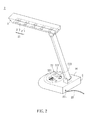
- FIG. 1 shows the structure of a conventional desktop lamp 1, which has a base 11, support unit 12 and an illumination unit 13.
- the support unit 12 is disposed on the base 11, and the illumination unit 13 is fixed on the support unit 12.
- the illumination unit 13 has a lamp 131 and a lampshade 132.
- the lamp 131 can emit light for illustration, and the lampshade 132 covers and protects the lamp 131.
- the lampshade 132 makes the light emitted from the lamp 131 downward.
- the base 11 has a switch 111 and a knob 112.
- the switch 111 is electrically connected to an external power line 14 for turning on or turning off the lamp 131.
- a power line 121 is disposed in the support unit 12 for electrically connecting the knob 112 and the lamp 131 of the illumination unit 13.
- the conventional illumination device usually has the light source of a single color, so that the customers do not have further choices for the light source. Therefore, it is an important subject of the invention to provide an illumination device that can provide the control of its lighting intensities of different color lights.
- the invention is to provide an illumination device that can provide the control of its lighting intensities of different color lights.
- the invention discloses an illumination device including an illumination unit and a control unit.
- the illumination unit has a plurality of light-emitting diodes (LEDs) emitting different colors of light and disposed adjacent to each other.
- the control unit is electrically connected with the LEDs for controlling the LEDs.
- the illumination device of the invention has the control unit for controlling the LEDs to emit light of different colors.
- the LED has the advantages of low power consumption, long lifetime, good color saturation, high light-emitting efficiency, and adjustable color temperature.
- the LED also provides stable light, increases its usage rate, saves energy, and reduces the cost.
- the invention uses a control unit to control the LEDs emitting light of different colors, so that the user can control the desired brightness and color. Accordingly, the illumination device of the invention has good practicability and attracts the user's attention.
- FIG. 1 is a schematic view showing the structure of a conventional illumination device
- FIG. 2 is a schematic view showing the structure of an illumination device according to a preferred embodiment of the invention.
- FIGS. 3A to 3C are schematic views showing different aspects of the control unit shown in FIG. 2 ;
- FIGS. 4A to 4C are schematic views showing the operations of the control unit shown in FIG. 3A
- FIG. 2 shows the structure of an illumination device 2 according to a preferred embodiment of the invention.
- the illumination device 2 can be a desktop lamp, a wall lamp, a hanging lamp, an incandescent lamp or a neon light.
- the illumination device 2 is, for example, a desktop lamp.
- the illumination device 2 includes an illumination unit 21 and a control unit 22 that are electrically connected with each other.
- the illumination unit 21 is disposed inside a lampshade A, which is disposed over a base D.
- the control unit 22 is disposed on a surface D1 of the base D.
- the illumination unit 21 provides the light for illumination.
- the illumination unit 21 has several light emitting diodes (LEDs) 211 disposed on a circuit board 212.
- the LEDs 211 include at least one red LED, at least one green LED, at least one blue LED, at least one yellow LED or at least one white-light LED.
- the LEDs 211 can be any color or a mixture of several colors according to the user's need.
- the LEDs 211 are disposed adjacent to each other, and emit light of different colors that are mixed in different proportions to provide desired color light. Therefore, in addition to white light, light of different colors can be produced to achieve certain effects.
- the control unit 22 has a brightness control area 221, a display area 222 and a switch 223.
- the bright control area 221 is electrically connected with the circuit board 212 of the illumination unit 21 for adjusting the brightness or lighting intensity of each LED 211, such as the green, blue, yellow or white-light LED.
- the control unit 22 can have different shape embodiments that are described below.
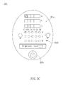
- FIGS. 3A to 3C are schematic views of different aspects of the control unit 22 in FIG. 2 .
- the brightness control area 221a/221c of the control unit 22a/22c is a touch-control panel.
- the brightness control area 221b of the control unit 22b is a knob.
- the user can use his/her finger or a touch-control pen to touch the brightness control area 221a/221c, thereby controlling the brightness and spectrum of the LEDs 211 in the illumination unit 21.
- the brightness control area 221c is a knob
- the user can turn it to adjust the brightness, spectrum and color temperature of the LEDs 211 in the illumination unit 21.
- the shape of the brightness control area 221 is not restricted by the invention. It can have a stripe shape (as shown in FIGS. 3A and 3C ), a saw shape (not shown), a spiral shape (not shown), a circular shape (not shown), a W shape (not shown), a Z shape (not shown), an e shape (not shown), or some irregular shapes.
- the brightness control area 221a can have different brightness control ranges according to the LEDs 211 of different colors in the illumination unit 21.
- the illumination unit 21 may include three LEDs 211, which respectively emit light of wavelengths 430nm, 555nm, and 630nm (Red, Green and Blue). If the illumination device 2 is used as a desktop lamp, the red, green and blue light emitted by the LEDs 211 can be mixed to form a white light, yellow light or any preferred color light depending on the applied current. If the illumination device 2 is used as the neon light of specific color, the lighting intensities of, for example, the red or green light can be increased to form the slight-red light or slight-green light.
- the brightness control area 221b can have a knob for controlling the brightness of the LEDs 211 of each color or the mixture brightness of all the LEDs 211.
- control unit 22 can further adjust the color temperature of the LEDs 211 of different colors using a control circuit (not shown) that is in electrical connection with the circuit board 212 of the illumination unit 21.
- the illumination unit 21 has LED series of red, green and blue colors (not shown). The LED series are connected in parallel via a resistor (not shown). The user can adjust the magnitudes of electrical currents flowing through the LED series by changing the resistance of the resistors.
- the user can use the above method or other conventional circuit control method to control the LEDs or LED series of different colors in the illumination unit 21 for rendering different brightness and color temperature. This produces different effects in order to suit seasonal changes or personal tastes.
- the brightness control area 221c is divided into several sections, each of which represents a distinct brightness level.
- the number of sections can be adjusted according to practical needs. This allows the user to readily determine the required brightness using the sections shown in the brightness control area 221c.
- the brightness can be touch-controlled as well.
- the user when the user wants to change the brightness from level 1 to level 3, he or she can touch the first section C1 in the brightness control area 221c and move to the third section C3, according to the definition of a circuit board (not sown) of the control unit 22c.
- the brightness increases along the direction from the first section C1 to the sixth section C6.
- the user can touch any section in the brightness control area 221c and move a distance of two sections in the brightness control area 221b. This also changes the brightness of the illumination unit 21 from the original level 1 to level 3.
- the user can also directly touch the third section C3 in the brightness control area 221c to change the brightness of the green light source to the level 3.
- the user has several ways to change the brightness of the illumination unit 21 using the brightness control area 221c. Any other way of changing the brightness of the illumination unit 21 using the touch-control method should be construed as part of the invention.
- the display area 222 is electrically connected with the illumination unit 21 for displaying the brightness level thereof.
- the display area 222 can be a liquid crystal display (LCD) panel (222a in FIG. 3A and 222b in FIG. 3B ), several light sources (not shown), or the combination of a display panel and LEDs (222c in FIG. 3C ).
- LCD liquid crystal display
- the display area 222 receives a change in the brightness of the illumination unit 21, as shown in FIGS. 3A or 3B , the brightness level of the illumination unit 21 is shown on the LCD panel.
- FIG. 3C such brightness level can be represented by the number of LEDs that are turned on.
- the display panel and the LEDs can be simultaneously used to show the brightness level of the illumination unit 21.
- the brightness level can be indicated by the color brightness.
- the brightness level can be indicated by numbers (as shown in FIG. 3C ).
- the display panel can use both methods at the same time. In other words, any method that uses the display panel to show the brightness level of the illumination unit 21 should be construed as part of the invention.
- the switch 223 is electrically connected with a power input terminal 224 of the control unit 22 in order to electrically connect with an external power line 23. This controls the on and off of the illumination device 2.
- the switch 223 can be a knob switch (223a in FIG. 3A ), a touch-control switch (223b in FIG. 3B ), or a button switch (223c in FIG. 3C ). Besides, the switch 223 can be disposed at any position.
- the control unit 22 may further have a situation touch-control area (not shown).
- the situation touch-control area has several touch-control buttons (not shown) for different situations.
- the illumination unit 21 consists of several red, blue and green LEDs
- the situation touch-control area has an illumination situation button, a read situation button, a sleep situation button and a candle situation button. They use predetermined parameter values to mix light of different colors and brightness, so that the user can press any of the situation buttons to quickly obtain desired brightness and color light.
- the illumination unit 21 includes a plurality of red LEDs, green LEDs and blue LEDs (not shown), and the LEDs are disposed adjacent to each other.
- the user turns the switch 223a of the control unit 22a so as to enable the illumination device 2.
- the brightness of the illumination device 2 can be controlled by the actions of touching the stripes R, G or B in brightness control area 221a and sliding toward desired directions.
- the illumination device of the invention has the control unit for controlling the LEDs to emit light of different colors.
- the LED has the advantages of low power consumption, long lifetime, good color saturation, high light-emitting efficiency, and adjustable color temperature.
- the LED also provides stable light, increases its usage rate, saves energy, and reduces the cost.
- the invention uses a control unit to control the LEDs emitting light of different colors, so that the user can control the desired brightness and color. Accordingly, the illumination device of the invention has good practicability and attracts the user's attention.
Abstract
Description
- The invention relates to an illumination device and, in particular, to an illumination device having light-emitting diodes (LEDs).
- Illustration devices are indispensable in many articles for daily use. In particular, illumination devices such as incandescent lamps, desktop lamps, hanging lamps, wall lamps, or neon lights have become very popular. They can not only brighten the dark but also blossom people's lives.
-
FIG. 1 shows the structure of aconventional desktop lamp 1, which has abase 11,support unit 12 and anillumination unit 13. Thesupport unit 12 is disposed on thebase 11, and theillumination unit 13 is fixed on thesupport unit 12. Theillumination unit 13 has alamp 131 and alampshade 132. Thelamp 131 can emit light for illustration, and thelampshade 132 covers and protects thelamp 131. Moreover, thelampshade 132 makes the light emitted from thelamp 131 downward. Thebase 11 has aswitch 111 and aknob 112. Theswitch 111 is electrically connected to anexternal power line 14 for turning on or turning off thelamp 131. In addition, apower line 121 is disposed in thesupport unit 12 for electrically connecting theknob 112 and thelamp 131 of theillumination unit 13. Thus, by controlling the current applied to thepower line 121, the brightness of the light emitted from thelamp 131 can be controlled. - However, simply using the
knob 112 to control the brightness of thedesktop lamp 1 can not satisfy the modern customers. In addition, the conventional illumination device usually has the light source of a single color, so that the customers do not have further choices for the light source. Therefore, it is an important subject of the invention to provide an illumination device that can provide the control of its lighting intensities of different color lights. - In view of the foregoing, the invention is to provide an illumination device that can provide the control of its lighting intensities of different color lights.
- To achieve the above, the invention discloses an illumination device including an illumination unit and a control unit. The illumination unit has a plurality of light-emitting diodes (LEDs) emitting different colors of light and disposed adjacent to each other. The control unit is electrically connected with the LEDs for controlling the LEDs.
- As mentioned above, the illumination device of the invention has the control unit for controlling the LEDs to emit light of different colors. Compared with the related art, the LED has the advantages of low power consumption, long lifetime, good color saturation, high light-emitting efficiency, and adjustable color temperature. In addition to being free from frequent replacements, the LED also provides stable light, increases its usage rate, saves energy, and reduces the cost. Besides, the invention uses a control unit to control the LEDs emitting light of different colors, so that the user can control the desired brightness and color. Accordingly, the illumination device of the invention has good practicability and attracts the user's attention.
- The invention will become more fully understood from the detailed description and accompanying drawings, which are given for illustration only, and thus are not limitative of the present invention, and wherein:
-
FIG. 1 is a schematic view showing the structure of a conventional illumination device; -
FIG. 2 is a schematic view showing the structure of an illumination device according to a preferred embodiment of the invention; -
FIGS. 3A to 3C are schematic views showing different aspects of the control unit shown inFIG. 2 ; and -
FIGS. 4A to 4C are schematic views showing the operations of the control unit shown inFIG. 3A - The present invention will be apparent from the following detailed description, which proceeds with reference to the accompanying drawings, wherein the same references relate to the same elements.
-
FIG. 2 shows the structure of anillumination device 2 according to a preferred embodiment of the invention. Theillumination device 2 can be a desktop lamp, a wall lamp, a hanging lamp, an incandescent lamp or a neon light. In the present embodiment, theillumination device 2 is, for example, a desktop lamp. The illumination device 2includes anillumination unit 21 and acontrol unit 22 that are electrically connected with each other. In this embodiment, theillumination unit 21 is disposed inside a lampshade A, which is disposed over a base D. Thecontrol unit 22 is disposed on a surface D1 of the base D. - The
illumination unit 21 provides the light for illumination. In the embodiment, theillumination unit 21 has several light emitting diodes (LEDs) 211 disposed on acircuit board 212. TheLEDs 211 include at least one red LED, at least one green LED, at least one blue LED, at least one yellow LED or at least one white-light LED. Of course, theLEDs 211 can be any color or a mixture of several colors according to the user's need. TheLEDs 211 are disposed adjacent to each other, and emit light of different colors that are mixed in different proportions to provide desired color light. Therefore, in addition to white light, light of different colors can be produced to achieve certain effects. - The
control unit 22 has abrightness control area 221, adisplay area 222 and aswitch 223. Thebright control area 221 is electrically connected with thecircuit board 212 of theillumination unit 21 for adjusting the brightness or lighting intensity of eachLED 211, such as the green, blue, yellow or white-light LED. Thecontrol unit 22 can have different shape embodiments that are described below. -
FIGS. 3A to 3C are schematic views of different aspects of thecontrol unit 22 inFIG. 2 . As shown inFIGS. 3A and3C , thebrightness control area 221a/221c of thecontrol unit 22a/22c is a touch-control panel. As shown inFIG. 3B , thebrightness control area 221b of thecontrol unit 22b is a knob. InFIGS. 3A and3C , when thebrightness control area 221a/221c is a touch-control panel, the user can use his/her finger or a touch-control pen to touch thebrightness control area 221a/221c, thereby controlling the brightness and spectrum of theLEDs 211 in theillumination unit 21. InFIG. 3B , when thebrightness control area 221c is a knob, the user can turn it to adjust the brightness, spectrum and color temperature of theLEDs 211 in theillumination unit 21. - The shape of the
brightness control area 221 is not restricted by the invention. It can have a stripe shape (as shown inFIGS. 3A and3C ), a saw shape (not shown), a spiral shape (not shown), a circular shape (not shown), a W shape (not shown), a Z shape (not shown), an e shape (not shown), or some irregular shapes. - In
FIG. 3A , thebrightness control area 221a can have different brightness control ranges according to theLEDs 211 of different colors in theillumination unit 21. For example, theillumination unit 21 may include threeLEDs 211, which respectively emit light of wavelengths 430nm, 555nm, and 630nm (Red, Green and Blue). If theillumination device 2 is used as a desktop lamp, the red, green and blue light emitted by theLEDs 211 can be mixed to form a white light, yellow light or any preferred color light depending on the applied current. If theillumination device 2 is used as the neon light of specific color, the lighting intensities of, for example, the red or green light can be increased to form the slight-red light or slight-green light. Alternatively, as shown inFIG. 3B , thebrightness control area 221b can have a knob for controlling the brightness of theLEDs 211 of each color or the mixture brightness of all theLEDs 211. - To be noted, in addition to adjusting brightness, the
control unit 22 can further adjust the color temperature of theLEDs 211 of different colors using a control circuit (not shown) that is in electrical connection with thecircuit board 212 of theillumination unit 21. For example, theillumination unit 21 has LED series of red, green and blue colors (not shown). The LED series are connected in parallel via a resistor (not shown). The user can adjust the magnitudes of electrical currents flowing through the LED series by changing the resistance of the resistors. - For example, if a larger electrical current flows through the red LED series, then the brightness and color temperature of red color produced thereby is larger. On the other hand, if the electrically current flowing through the red LED series is smaller, the brightness and color temperature produced by the red LED series is lower. Therefore, the user can use the above method or other conventional circuit control method to control the LEDs or LED series of different colors in the
illumination unit 21 for rendering different brightness and color temperature. This produces different effects in order to suit seasonal changes or personal tastes. - As shown in
FIG. 3C , thebrightness control area 221c is divided into several sections, each of which represents a distinct brightness level. Of course, the number of sections can be adjusted according to practical needs. This allows the user to readily determine the required brightness using the sections shown in thebrightness control area 221c. The brightness can be touch-controlled as well. - For example, as showing in
FIG. 3C , when the user wants to change the brightness fromlevel 1 to level 3, he or she can touch the first section C1 in thebrightness control area 221c and move to the third section C3, according to the definition of a circuit board (not sown) of thecontrol unit 22c. In the embodiment, the brightness increases along the direction from the first section C1 to the sixth section C6. Alternatively, the user can touch any section in thebrightness control area 221c and move a distance of two sections in thebrightness control area 221b. This also changes the brightness of theillumination unit 21 from theoriginal level 1 to level 3. Of course, the user can also directly touch the third section C3 in thebrightness control area 221c to change the brightness of the green light source to the level 3. In practice, the user has several ways to change the brightness of theillumination unit 21 using thebrightness control area 221c. Any other way of changing the brightness of theillumination unit 21 using the touch-control method should be construed as part of the invention. - Please refer to
FIG. 2 again. Thedisplay area 222 is electrically connected with theillumination unit 21 for displaying the brightness level thereof. In particular, thedisplay area 222 can be a liquid crystal display (LCD) panel (222a inFIG. 3A and 222b inFIG. 3B ), several light sources (not shown), or the combination of a display panel and LEDs (222c inFIG. 3C ). When thedisplay area 222 receives a change in the brightness of theillumination unit 21, as shown inFIGS. 3A or 3B , the brightness level of theillumination unit 21 is shown on the LCD panel. Alternatively, as shown inFIG. 3C , such brightness level can be represented by the number of LEDs that are turned on. Moreover, the display panel and the LEDs can be simultaneously used to show the brightness level of theillumination unit 21. - When the
display area 222 is adisplay panel 222a as shown inFIG. 3A , the brightness level can be indicated by the color brightness. Alternatively, as shown inFIG. 3C , the brightness level can be indicated by numbers (as shown inFIG. 3C ). Of course, the display panel can use both methods at the same time. In other words, any method that uses the display panel to show the brightness level of theillumination unit 21 should be construed as part of the invention. - With reference to
FIG. 2 , theswitch 223 is electrically connected with apower input terminal 224 of thecontrol unit 22 in order to electrically connect with anexternal power line 23. This controls the on and off of theillumination device 2. Theswitch 223 can be a knob switch (223a inFIG. 3A ), a touch-control switch (223b inFIG. 3B ), or a button switch (223c inFIG. 3C ). Besides, theswitch 223 can be disposed at any position. - The
control unit 22 may further have a situation touch-control area (not shown). According to the type of theillumination unit 21, the situation touch-control area has several touch-control buttons (not shown) for different situations. For example, if theillumination unit 21 consists of several red, blue and green LEDs, then the situation touch-control area has an illumination situation button, a read situation button, a sleep situation button and a candle situation button. They use predetermined parameter values to mix light of different colors and brightness, so that the user can press any of the situation buttons to quickly obtain desired brightness and color light. - With reference to
FIGS. 4A to 4C , to make the above-mentioned embodiment more comprehensive, the operation of thecontrol unit 22a shown inFIG. 3A will be described hereinafter. In this embodiment, theillumination unit 21 includes a plurality of red LEDs, green LEDs and blue LEDs (not shown), and the LEDs are disposed adjacent to each other. - First, the user turns the
switch 223a of thecontrol unit 22a so as to enable theillumination device 2. - Then, as shown in
FIG. 4A , when the user needs red or sfight-red light, he/she can touch the stripe R, which represents red light, in thebrightness control area 221a, and slide toward the direction of increasing brightness. Accordingly, the brightness of the red LEDs increases as more area in the stripe R is slid. - As shown in
FIG. 4B , if the user thinks that the brightness of the green LED is lower and that of the red LED is higher, he/she can touch the stripe G, which represents green light, in thebrightness control area 221a, and slide toward the direction of increasing brightness. Then, he/she can further touch the stripe R and slide toward the direction of decreasing brightness. Accordingly, the brightness of the green LEDs increases as more area in the stripe G is slid, and the brightness of the red LEDs decreases as more area in the stripe R is slid. - As shown in
FIG. 4C , if the user thinks that the brightness of the blue LED is lower and that of the green LED is higher, he/she can touch the stripe B, which represents blue light, in thebrightness control area 221a, and slide toward the direction of increasing brightness. Then, he/she can further touch the stripe G and slide toward the direction of decreasing brightness. Accordingly, the brightness of the blue LEDs increases as more area in the stripe B is slid, and the brightness of the green LEDs decreases as more area in the stripe G is slid. - In the above operations, the brightness of the
illumination device 2 can be controlled by the actions of touching the stripes R, G or B inbrightness control area 221a and sliding toward desired directions. - In summary, the illumination device of the invention has the control unit for controlling the LEDs to emit light of different colors. Compared with the related art, the LED has the advantages of low power consumption, long lifetime, good color saturation, high light-emitting efficiency, and adjustable color temperature. In addition to being free from frequent replacements, the LED also provides stable light, increases its usage rate, saves energy, and reduces the cost. Besides, the invention uses a control unit to control the LEDs emitting light of different colors, so that the user can control the desired brightness and color. Accordingly, the illumination device of the invention has good practicability and attracts the user's attention.
- Although the invention has been described with reference to specific embodiments, this description is not meant to be construed in a limiting sense. Various modifications of the disclosed embodiments, as well as alternative embodiments, will be apparent to persons skilled in the art. It is, therefore, contemplated that the appended claims will cover all modifications that fall within the true scope of the invention.
Claims (9)
- An illumination device (2), comprising:an illumination unit (21), which has a plurality of light-emitting diodes (211) emitting different colors of light and disposed adjacent to each other; anda control unit (22), which is electrically connected with the light-emitting diodes (211) for controlling the light-emitting diodes (211).
- The illumination device (2) of claim 1, wherein the control unit (22; 22a/b/c) has a brightness control area (221), and the brightness control area (221a/b/c) is a touch-control panel or a knob.
- The illumination device (2) of claim 2, wherein the brightness control area (221b) has a stripe shape, a circular shape, a saw shape, a spiral shape, a W shape, a Z shape, or an irregular shape.
- The illumination device (2) of claim 1, wherein the control unit (22) has a display area (222) showing a brightness of the illumination unit (21).
- The illumination device (2) of claim 1, wherein the control unit (22) has a switch (223) and the switch is a touch-control switch (223a), a button switch (223c), or a knob switch (223b).
- The illumination device (2) of claim 1, further comprising:a base (D); anda lampshade (A), which is disposed over the base (D), wherein the control unit (22) is disposed on one surface (D1) of the base (D), and the illumination unit (21) is disposed in the lampshade (A).
- The illumination device (2) of claim 1, wherein the light-emitting diodes (211) at least includes a red light-emitting diode, a green light-emitting diode or a blue light-emitting diode.
- The illumination device (2) of claim 1, wherein the illumination unit (21) further comprises a circuit board (212), and the light-emitting diodes (211) are disposed on the circuit board (212).
- The illumination device (2) of claim 1, wherein the control unit (22) has a control circuit for controlling a brightness or a color temperature of each of the light-emitting diodes (211).
Applications Claiming Priority (1)
| Application Number | Priority Date | Filing Date | Title |
|---|---|---|---|
| CNA2007101111181A CN101324308A (en) | 2007-06-11 | 2007-06-11 | Illumination device |
Publications (2)
| Publication Number | Publication Date |
|---|---|
| EP2003392A2 true EP2003392A2 (en) | 2008-12-17 |
| EP2003392A3 EP2003392A3 (en) | 2009-07-15 |
Family
ID=39735491
Family Applications (1)
| Application Number | Title | Priority Date | Filing Date |
|---|---|---|---|
| EP07118936A Withdrawn EP2003392A3 (en) | 2007-06-11 | 2007-10-19 | Illumination device |
Country Status (2)
| Country | Link |
|---|---|
| EP (1) | EP2003392A3 (en) |
| CN (1) | CN101324308A (en) |
Cited By (6)
| Publication number | Priority date | Publication date | Assignee | Title |
|---|---|---|---|---|
| WO2010131179A1 (en) * | 2009-05-13 | 2010-11-18 | Koninklijke Philips Electronics N.V. | Sharp transition in circular light guided ring for user interface with functionalities with a clear beginning and end |
| FR2947612A1 (en) * | 2009-07-06 | 2011-01-07 | Naotek | ORCHESTRA LUMINAIRE WITH ADJUSTABLE COLOR TEMPERATURE |
| JP2013115039A (en) * | 2011-11-24 | 2013-06-10 | Lextar Electronics Corp | Light adjustment device and light system including the same |
| CN105530727A (en) * | 2016-02-02 | 2016-04-27 | 刘顺 | Dual-induction type LED wall lamp |
| EP3379903A4 (en) * | 2015-12-21 | 2019-08-07 | Shenzhen Royole Technologies Co. Ltd. | Switch control apparatus and switch control method |
| CN111649252A (en) * | 2020-06-29 | 2020-09-11 | 曾国庆 | LED lamp capable of automatically adjusting light |
Families Citing this family (11)
| Publication number | Priority date | Publication date | Assignee | Title |
|---|---|---|---|---|
| CN102635789B (en) * | 2011-02-10 | 2014-11-26 | 鹤山市银雨照明有限公司 | LED (light emitting diode) fluorescent tube |
| CN102781135A (en) * | 2011-05-13 | 2012-11-14 | 君曜科技股份有限公司 | Method and system for coding palette |
| CN102889493A (en) * | 2011-07-20 | 2013-01-23 | 上海亮硕光电子科技有限公司 | LED (light-emitting diode) desk lamp with adjustable color temperature |
| CN102927491B (en) * | 2012-11-02 | 2016-04-06 | 深圳三马电器有限公司 | A kind of color-changing desk lamp |
| CN102980106A (en) * | 2012-12-06 | 2013-03-20 | 程建英 | Multi-functional bed lamp |
| CN103322498A (en) * | 2013-04-07 | 2013-09-25 | 苏州科大微龙信息技术有限公司 | LED eye protection table lamp |
| CN104141905B (en) * | 2013-05-07 | 2016-09-07 | 苏州欧普照明有限公司 | A kind of light fixture |
| CN105627262A (en) * | 2015-12-25 | 2016-06-01 | 苏州拾向梦数字媒体有限公司 | Intelligent interaction touch panel system |
| CN110710332A (en) * | 2016-11-24 | 2020-01-17 | 昕诺飞控股有限公司 | Lighting controller |
| CN108882472A (en) * | 2017-05-08 | 2018-11-23 | 怀化学院 | A kind of Light Controlling Street Lamp Controller and its control method |
| CN107091463A (en) * | 2017-05-20 | 2017-08-25 | 金勇� | One kind becomes brightness lampshade |
Citations (9)
| Publication number | Priority date | Publication date | Assignee | Title |
|---|---|---|---|---|
| US20060064144A1 (en) * | 2004-06-25 | 2006-03-23 | Chen Joshua Q | Programmable multifunction table lamp for light therapy |
| US20060076908A1 (en) * | 2004-09-10 | 2006-04-13 | Color Kinetics Incorporated | Lighting zone control methods and apparatus |
| WO2006129256A2 (en) * | 2005-06-01 | 2006-12-07 | Koninklijke Philips Electronics, N.V. | Sunny-cloudy scale for setting color temperature of white lights |
| EP1623602B1 (en) * | 2003-05-07 | 2007-03-07 | Koninklijke Philips Electronics N.V. | User interface for controlling light emitting diodes |
| US20070052376A1 (en) * | 2005-08-09 | 2007-03-08 | Wei-Chiang Lee | Full-color led-based lighting device |
| EP1785665A1 (en) * | 2005-11-14 | 2007-05-16 | TRUMPF Kreuzer Medizin Systeme GmbH + Co. KG | Surgical lamp |
| WO2007069185A1 (en) * | 2005-12-12 | 2007-06-21 | Koninklijke Philips Electronics N.V. | Lamp assembly |
| WO2007072294A1 (en) * | 2005-12-22 | 2007-06-28 | Koninklijke Philips Electronics N.V. | Button arrangement for colored lighting controller |
| US20080291673A1 (en) * | 2007-05-22 | 2008-11-27 | Prodisc Technology Inc. | Illumination device |
-
2007
- 2007-06-11 CN CNA2007101111181A patent/CN101324308A/en active Pending
- 2007-10-19 EP EP07118936A patent/EP2003392A3/en not_active Withdrawn
Patent Citations (9)
| Publication number | Priority date | Publication date | Assignee | Title |
|---|---|---|---|---|
| EP1623602B1 (en) * | 2003-05-07 | 2007-03-07 | Koninklijke Philips Electronics N.V. | User interface for controlling light emitting diodes |
| US20060064144A1 (en) * | 2004-06-25 | 2006-03-23 | Chen Joshua Q | Programmable multifunction table lamp for light therapy |
| US20060076908A1 (en) * | 2004-09-10 | 2006-04-13 | Color Kinetics Incorporated | Lighting zone control methods and apparatus |
| WO2006129256A2 (en) * | 2005-06-01 | 2006-12-07 | Koninklijke Philips Electronics, N.V. | Sunny-cloudy scale for setting color temperature of white lights |
| US20070052376A1 (en) * | 2005-08-09 | 2007-03-08 | Wei-Chiang Lee | Full-color led-based lighting device |
| EP1785665A1 (en) * | 2005-11-14 | 2007-05-16 | TRUMPF Kreuzer Medizin Systeme GmbH + Co. KG | Surgical lamp |
| WO2007069185A1 (en) * | 2005-12-12 | 2007-06-21 | Koninklijke Philips Electronics N.V. | Lamp assembly |
| WO2007072294A1 (en) * | 2005-12-22 | 2007-06-28 | Koninklijke Philips Electronics N.V. | Button arrangement for colored lighting controller |
| US20080291673A1 (en) * | 2007-05-22 | 2008-11-27 | Prodisc Technology Inc. | Illumination device |
Cited By (9)
| Publication number | Priority date | Publication date | Assignee | Title |
|---|---|---|---|---|
| WO2010131179A1 (en) * | 2009-05-13 | 2010-11-18 | Koninklijke Philips Electronics N.V. | Sharp transition in circular light guided ring for user interface with functionalities with a clear beginning and end |
| US9084329B2 (en) | 2009-05-13 | 2015-07-14 | Koninklijke Philips N.V. | Lighting control device having a touch sensitive user interface |
| RU2562097C2 (en) * | 2009-05-13 | 2015-09-10 | Конинклейке Филипс Электроникс Н.В. | Abrupt transfer in circular waveguide ring for user's interface with operating performances of definite star and end |
| FR2947612A1 (en) * | 2009-07-06 | 2011-01-07 | Naotek | ORCHESTRA LUMINAIRE WITH ADJUSTABLE COLOR TEMPERATURE |
| EP2273187A1 (en) * | 2009-07-06 | 2011-01-12 | Naotek | Music stand luminaire with adjustable colour temperature |
| JP2013115039A (en) * | 2011-11-24 | 2013-06-10 | Lextar Electronics Corp | Light adjustment device and light system including the same |
| EP3379903A4 (en) * | 2015-12-21 | 2019-08-07 | Shenzhen Royole Technologies Co. Ltd. | Switch control apparatus and switch control method |
| CN105530727A (en) * | 2016-02-02 | 2016-04-27 | 刘顺 | Dual-induction type LED wall lamp |
| CN111649252A (en) * | 2020-06-29 | 2020-09-11 | 曾国庆 | LED lamp capable of automatically adjusting light |
Also Published As
| Publication number | Publication date |
|---|---|
| CN101324308A (en) | 2008-12-17 |
| EP2003392A3 (en) | 2009-07-15 |
Similar Documents
| Publication | Publication Date | Title |
|---|---|---|
| EP2003392A2 (en) | Illumination device | |
| US20080291673A1 (en) | Illumination device | |
| US20080290816A1 (en) | Aquarium lighting device | |
| EP2002713A2 (en) | Aquarium lighting device | |
| JP5426802B1 (en) | Light emitting circuit, light emitting module, and lighting device | |
| CN101839435B (en) | Illumination device and controller thereof | |
| EP2375861B1 (en) | Light emitting device | |
| EP1876385B1 (en) | Lamp and bulb for illumination and ambiance lighting | |
| US7988323B2 (en) | Lighting devices for illumination and ambiance lighting | |
| CA2765596C (en) | Dimmable light source with light temperature shift | |
| CN102563417B (en) | Illuminating device | |
| TWM295720U (en) | LED full-color display lamp | |
| KR20070011571A (en) | Lighting device with user interface for light control | |
| US20070165406A1 (en) | Display with an illuminating light | |
| CN101341462A (en) | Button arrangement for colored lighting controller | |
| JP2010176986A (en) | Color temperature variable lighting system and controller used in same | |
| US11483908B1 (en) | 3-way dimming brightness and color temperature control | |
| US10757777B1 (en) | Brightness adjustment for a white-light lamp | |
| KR101040618B1 (en) | Marine Chart Table Light | |
| JP5807208B2 (en) | Color temperature variable lighting device | |
| KR101034539B1 (en) | Manufacturing method of chart table light for ship | |
| CN219912971U (en) | Lamp cap and lamp | |
| CN213638278U (en) | Sliding touch dimming LED table lamp | |
| CN217064059U (en) | Dialing electrodeless color matching application circuit | |
| CN208090641U (en) | A kind of brightness adjustment control panel |
Legal Events
| Date | Code | Title | Description |
|---|---|---|---|
| PUAI | Public reference made under article 153(3) epc to a published international application that has entered the european phase |
Free format text: ORIGINAL CODE: 0009012 |
|
| AK | Designated contracting states |
Kind code of ref document: A2 Designated state(s): AT BE BG CH CY CZ DE DK EE ES FI FR GB GR HU IE IS IT LI LT LU LV MC MT NL PL PT RO SE SI SK TR |
|
| AX | Request for extension of the european patent |
Extension state: AL BA HR MK RS |
|
| PUAL | Search report despatched |
Free format text: ORIGINAL CODE: 0009013 |
|
| AK | Designated contracting states |
Kind code of ref document: A3 Designated state(s): AT BE BG CH CY CZ DE DK EE ES FI FR GB GR HU IE IS IT LI LT LU LV MC MT NL PL PT RO SE SI SK TR |
|
| AX | Request for extension of the european patent |
Extension state: AL BA HR MK RS |
|
| RIC1 | Information provided on ipc code assigned before grant |
Ipc: F21Y 101/02 20060101ALN20080916BHEP Ipc: H05B 37/00 20060101ALI20090610BHEP Ipc: H05B 33/08 20060101ALI20090610BHEP Ipc: F21S 6/00 20060101ALI20090610BHEP Ipc: F21S 10/02 20060101AFI20080916BHEP |
|
| AKX | Designation fees paid | ||
| STAA | Information on the status of an ep patent application or granted ep patent |
Free format text: STATUS: THE APPLICATION IS DEEMED TO BE WITHDRAWN |
|
| 18D | Application deemed to be withdrawn |
Effective date: 20100116 |
|
| REG | Reference to a national code |
Ref country code: DE Ref legal event code: 8566 |