EP2002039B1 - Double layer papermakers fabric with pockets for bulk enhancement - Google Patents
Double layer papermakers fabric with pockets for bulk enhancement Download PDFInfo
- Publication number
- EP2002039B1 EP2002039B1 EP07752895A EP07752895A EP2002039B1 EP 2002039 B1 EP2002039 B1 EP 2002039B1 EP 07752895 A EP07752895 A EP 07752895A EP 07752895 A EP07752895 A EP 07752895A EP 2002039 B1 EP2002039 B1 EP 2002039B1
- Authority
- EP
- European Patent Office
- Prior art keywords
- fabric
- yarns
- pockets
- warp
- weft
- Prior art date
- Legal status (The legal status is an assumption and is not a legal conclusion. Google has not performed a legal analysis and makes no representation as to the accuracy of the status listed.)
- Not-in-force
Links
- 239000004744 fabric Substances 0.000 title claims abstract description 160
- 238000007605 air drying Methods 0.000 abstract description 5
- 239000010410 layer Substances 0.000 description 12
- 238000010586 diagram Methods 0.000 description 7
- 238000000034 method Methods 0.000 description 7
- 230000035699 permeability Effects 0.000 description 6
- 230000015572 biosynthetic process Effects 0.000 description 5
- 230000008569 process Effects 0.000 description 5
- 230000001965 increasing effect Effects 0.000 description 4
- 230000009286 beneficial effect Effects 0.000 description 3
- 230000000694 effects Effects 0.000 description 3
- 235000014676 Phragmites communis Nutrition 0.000 description 2
- 230000008901 benefit Effects 0.000 description 2
- 238000010276 construction Methods 0.000 description 2
- 230000002708 enhancing effect Effects 0.000 description 2
- 239000000835 fiber Substances 0.000 description 2
- 238000004519 manufacturing process Methods 0.000 description 2
- 239000000463 material Substances 0.000 description 2
- 238000012986 modification Methods 0.000 description 2
- 230000004048 modification Effects 0.000 description 2
- -1 polyethylene terephthalate Polymers 0.000 description 2
- 229920000139 polyethylene terephthalate Polymers 0.000 description 2
- 239000005020 polyethylene terephthalate Substances 0.000 description 2
- 239000002356 single layer Substances 0.000 description 2
- 238000012876 topography Methods 0.000 description 2
- 238000009941 weaving Methods 0.000 description 2
- 239000004698 Polyethylene Substances 0.000 description 1
- 238000005299 abrasion Methods 0.000 description 1
- 230000002745 absorbent Effects 0.000 description 1
- 239000002250 absorbent Substances 0.000 description 1
- 238000004026 adhesive bonding Methods 0.000 description 1
- 230000003247 decreasing effect Effects 0.000 description 1
- 238000000151 deposition Methods 0.000 description 1
- 238000001035 drying Methods 0.000 description 1
- 239000003292 glue Substances 0.000 description 1
- 238000009998 heat setting Methods 0.000 description 1
- 230000008676 import Effects 0.000 description 1
- 230000006872 improvement Effects 0.000 description 1
- 238000000059 patterning Methods 0.000 description 1
- 229920000573 polyethylene Polymers 0.000 description 1
- 238000003825 pressing Methods 0.000 description 1
- 230000002787 reinforcement Effects 0.000 description 1
- 238000004826 seaming Methods 0.000 description 1
- 239000000758 substrate Substances 0.000 description 1
- 230000003746 surface roughness Effects 0.000 description 1
- XLYOFNOQVPJJNP-UHFFFAOYSA-N water Substances O XLYOFNOQVPJJNP-UHFFFAOYSA-N 0.000 description 1
Images


Classifications
-
- D—TEXTILES; PAPER
- D21—PAPER-MAKING; PRODUCTION OF CELLULOSE
- D21F—PAPER-MAKING MACHINES; METHODS OF PRODUCING PAPER THEREON
- D21F1/00—Wet end of machines for making continuous webs of paper
- D21F1/0027—Screen-cloths
- D21F1/0036—Multi-layer screen-cloths
-
- D—TEXTILES; PAPER
- D21—PAPER-MAKING; PRODUCTION OF CELLULOSE
- D21F—PAPER-MAKING MACHINES; METHODS OF PRODUCING PAPER THEREON
- D21F11/00—Processes for making continuous lengths of paper, or of cardboard, or of wet web for fibre board production, on paper-making machines
- D21F11/14—Making cellulose wadding, filter or blotting paper
- D21F11/145—Making cellulose wadding, filter or blotting paper including a through-drying process
Definitions
- the invention relates to papermakers fabrics, and in particular to an improved through-air-drying (TAD) fabric for creating a sheet with enhanced bulk, typically for tissue and towel applications.
- TAD through-air-drying
- the majority of towel and issue products are presently manufactured according to one of either the conventional wet pressing (CWP) or through-air drying (TAD) processes.
- CWP wet pressing
- TAD through-air drying
- a disadvantage of this process is that it densities the web, decreasing bulk and absorbency in the resultant sheet.
- the TAD process is frequently preferred for the manufacture of tissue and towel because it avoids the compressive forces of the dewatering step in the CWP method.
- the wet web is formed by depositing a papermaking furnish onto a moving forming fabric where it is initially drained, and then transferring the resulting very wet web onto a TAD fabric, which is generally of a very open and permeable design.
- the TAD fabric is caused to travel around an open drum where the sheet is non-compressively dried by passing hot air through the web while it is held in intimate contact with the fabric.
- fabrics having a three-dimensional (i.e. non-planar) paper side surface can introduce protuberances into the sheet which can, in turn, impart significantly increased bulk and absorbent capacity to the resulting paper product.
- the present invention is directed towards fabrics of this type.
- Fabrics for use in the formation and through-air drying of tissue products to enhance the bulk of those products are well known. See for example WO 2005/035867 to Lafond et al . which discloses a multilayer tissue forming fabric having topographical height differences between at least two top weft yarns.
- US 2004/0182466 to Johnson et al discloses a multilayer TAD fabric with two weft and one warp system in which the pattern causes the warp yarns to stand proud of the papermaking surface to impart bulk.
- US 6673202 to Burazin et al discloses patterning and bulk enhancement in a TAD fabric by applying a polymeric material onto a substrate fabric.
- US 4438788 to Harwood discloses a papermakers fabric having surface floats on both the PS and MS for improved sheet contact area and improved abrasion resistance.
- the fabric also includes a plurality of stuffer pick receiving sheds defined by warp yarns of non-circular generally rectangular cross section. The amount of stuffer picks used in the fabric will depend on the air permeability desired.
- a pin seam is created at the opposing fabric ends by symmetrically reweaving the warp yarns into the fabric to create the seaming loops.
- the fabric includes three layers of weft yarns interwoven with a single system of warp yarns to provide a smooth surface and high degree of contact with the paper sheet to increase drying efficiency. There is no disclosure of the use of this fabric to provide a PS which includes pockets or depressions to enhance the bulk of a paper sheet formed or conveyed thereon.
- WO2006/1138 discloses a through air during fabric for producing tissue and related products.
- the fabric is a single layer fabric that includes pockets on both sides bounded by warp and weft yarns having extended floats.
- the yarns within the pockets are woven in a plain weave.
- Three different warp contours for the warp yarns are required, making the fabric more complex to weave and resulting in non-uniformities.
- EP 0 839 955 discloses a forming fabric for a high bulk paper web. In one embodiment, shown in Figs. 2A - 2D therein, there are three layers of weft yarns interwoven with a warp yarn system. Pockets are formed on the paper support surface using a coarse first layer of weft yarns.
- a second, machine side layer of fine weft yarns is provided.
- the third intermediate layer of coarse weft yarns is stacked directly under the first layer of coarse weft yarns.
- the pocket bottoms are formed by the warp yarns. This arrangement places the fine yarns in a higher wear position on the machine side.
- the invention concerns a double layer papermakers' fabric suitable for use in forming or through-air drying (TAD) of tissue or towel where it is important to impart a measure of bulk into the product being conveyed.
- the fabric is comprised of a single warp yarn system interwoven with three weft yarn systems such that a first of the weft yarn systems is located on the paper side (PS) surface of the fabric, a second of the weft yarn systems is located on the machine side (MS) surface of the fabric, and the third weft yarn system is located intermediate between the first and second weft yarn systems.
- the yarns of the first and second weft yarn systems are located in vertically stacked relationship with respect to one another in the fabric and are interwoven with the warp yarns according to an asymmetric design so as to form generally rectangular pockets on each of the PS and MS of the fabric.
- the yarns of the third weft yarn system are located in a central plane of the fabric, intermediate of the first and second weft yarn systems and in between vertically stacked pairs of weft yarns of the first and second weft yarn systems so as to form the "bottom" of each pocket.
- These pockets impart a surface roughness to the fabric which assists in creating bulk in the sheet formed or conveyed thereon, while still providing for a low sheet contact area and a high air permeability, which are beneficial in TAD applications.
- the fabric is woven according to a 5-shed asymmetric pattern, but other patterns are possible which embody the features of the invention and which can be woven in differing numbers of sheds.
- the contact area between the fabric and sheet is ⁇ 30%; more preferably, the contact area is ⁇ 25%, and most preferably is as low as from 15% to about 20%.
- each pocket as measured from the paper side surface of the fabric to the surface of the weft yarn forming the bottom of the pocket, ranges from about 0.1 to about 1.0 mm.
- the number of pockets on the PS surface ranges from 50 to 750 pockets per sq. in. (8 pockets per sq cm to 116 pockets per sq cm), and more preferably are in the range of 60 - 150 pockets per sq. in. (9.3 to 23.2 pockets per sq cm)
- the PS pockets which are formed have at least three PS warp knuckles that define the corners of the pockets.
- a majority of the pockets are "full” defined by alternate warp yarns, with an intermediate warp yarn that is beneath the pocket. Additionally, a lesser number of "half" pockets which are defined between adjacent warp yarns are provided. Preferably, at least 2/3 of the pockets on PS are full pockets.
- the warp yarns are paired in the fabric, providing a greater number of full pockets, which is believed to be beneficial In imparting or enhancing bulk.
- the air permeability is in the range of 450 cubic feet per minute (cfm) (7,300 m 3 /m 2 /hr) to 1200 cfm (19,450 m 3 /m 2 /hr).
- the fabric mesh is from 30 to 70 warp yarns per inch (11.8 to 27.6 warp per cm) and 30 to 60 weft per inch (11.8 to 23.6 weft per cm) for TAD applications.
- the fabric mesh is from 70 warp or weft per inch (27.56 yarns per cm) to about 100 yarns per inch (39.37 yarns per cm) for tissue forming applications.
- warp and weft yarns are preferably heat stabilized.
- the fabrics according to the invention have a caliper of about 0.035 in. to 0.065 in. (0.89mm to 1.65mm). In a second preferred configuration, the fabrics have a caliper of about 0.018 to 0.040 inches (0.46 mm to 1.02 mm)
- the papermakers' fabric construction is particularly suited for use in a forming section of a papermaking machine, in particular in tissue applications, where it is desirable to impart bulk in the tissue sheet being formed.
- the construction of the fabric is similar to the TAD fabric, as discussed above, except that different yarn sizes are utilized for the warp and weft yarns, and the fabric permeability is preferably lower to provide for good sheet formation.
- the pockets trap and enhance the bulk of the sheet being formed, with the pocket formation of the present invention acting to enhance sheet release and prevent the fibers from becoming lodged or entangled in the fabric.
- Figure 1 is a perspective view of a fabric according to the invention, showing the pockets in the paper side surface.
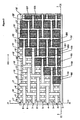
- Figure 2 is an orthographic perspective of a first surface of the fabric shown in Figure 1 .
- Figure 3 is a cross-section taken along the plane III - III passing through the weft yarns along the warp yarns of the fabric shown in Figure 1 .
- Figure 4 is a cross section taken along the plane IV - IV passing through the warp yarns and along the weft yarns of the fabric shown in Figure 1 .
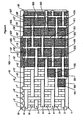
- Figure 5 is an orthographic perspective of second embodiment of a fabric according to the invention.
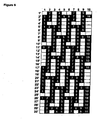
- Figure 6 is the weave diagram of the fabric shown in the Figures.
- Figure 7 is a photograph of a first surface of a fabric woven according to the weave design shown in Figure 6 , corresponding to the illustration of Figure 5 .
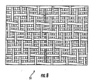
- Figure 8 is a photograph of a second surface of a fabric woven according the weave design shown in Figure 6 and is the surface of the fabric located opposite the surface shown in Figure 7 and Figure 5 .
- top and bottom designate directions in the drawings to which reference is made. This terminology includes the words specifically noted above, derivatives thereof and words of similar import.
- MD refers to the machine direction that a papermaker's fabric travels in a papermaking machine.
- CD refers to the cross-machine direction.
- PS refers to the paper or sheet supporting surface of the fabric and
- MS refers to the machine contact side of the fabric.
- Pocket refers to a recess defined by crossing warp and weft yarns that is open toward the PS or MS of the fabric and bounded on its bottom by at least an intermediate layer weft yarn.
- a “full” pocket refers to a pocket that is defined by two boundary warp yarns that are spaced apart by another warp yarn, with the boundary warp yarns having at least three MS or PS warp knuckles that define corners of the pocket.
- a “half' pocket refers to a pocket that is defined by two boundary warp yarns that are adjacent to one another, with the boundary warp yarns having at least two MS or PS warp knuckles that define corners of the pocket. Additionally, the terms "a” and “one” are defined as including one or more of the referenced item unless specifically noted.
- FIG. 1 a perspective view of a first embodiment of a fabric according to the invention is shown which is presently preferred and is generally designated as 50.
- the warp yarns are numbered from 1 to 10
- the weft yarns are numbered from 1' to 30'.
- Weft yarns of the first weft yarn system are numbered 1', 4', 7', 10', 13', 16', 19', 22', 25' and 28' and are interwoven with the warp yarns 1 through 10 to form a first generally planar surface 60 of the fabric 50 which, when in use, generally contacts a paper sheet being carried by the fabric and is thus the PS.
- Weft yarns of the second weft yarn system are numbered 2', 5', 8', 11', 14', 17', 20', 23', 26' and 29' and are also interwoven with the warp yarns 1 through 10 to form a second generally planar surface 70 of the fabric 50 which, when in use, generally contacts the supporting rolls and drive rolls and is thus the MS of the fabric.
- Weft yarns of the third weft yarn system are numbered 3', 6', 9', 12', 15', 18', 21', 24', 27' and 30' and are interwoven with the warp yarns 1 - 10 so as to be located generally in a centre plane 80 in the fabric 50, as indicated in Figures 3 and 4 , which is located intermediate of first planar surface 60 and second planar surface 70.
- the basic repeat unit of the weave pattern of the fabric 50 is a 5 x 15 pattern, meaning there are 5 warp yarns and 15 weft yarns in one repeat.
- warp 1 - 5 are interwoven with weft 1' through 15' to form the basic 5 shed repeat unit.
- the weave pattern of the fabric illustrated in Figures 1 - 5 is shown in Figure 6 .
- the warp yarns 1, 2, 3 through 10 are interwoven with the weft yarns 1', 2', 3', 4', 5', ... 30' according to a pattern which provides for pockets designated 100, 101, 103, 105, 107, 200, 201, 203, 205, 207 in the first surface 60 of the fabric 50, which surface may be used to receive the paper sheet.
- two different types of pockets are formed. This includes full pockets, designated generally as 100, and including representative full pockets 101, 103, 105, 107 shown in Figure 1 , formed on the PS of the fabric 50.
- Half pockets, generally designated as 200, and including representative half pockets 201. 203, 205, 207 shown in Figure 1 are also formed on the PS.
- the full pockets 100 appear in surface locations between certain next adjacent portions of the warp yarns 1 - 10, and include three PS warp knuckles that define the corners in conjunction with first or top layer weft yarns 1', 4', 7', 10', 13', 16', 19', 22', 25' and 28'.
- the half pockets 200 are located in the weave between certain adjacent portions of the warp yarns 1 - 10, as shown, and include two PS warp knuckles that define corners in conjunction with first or top layer weft yarns 1', 4', 7', 10', 13', 16', 19', 22', 25' and 28'.
- full pocket 101 is bounded on the surface 60 by warp yarns 1 and 3, weft yarns 7' and 10', and the bottom of the pocket is formed by weft 9'.
- half pocket 201 is bounded by warp yarns 1 and 2, weft 16' and 19' and the bottom of pocket 201 is provided by weft 18' which is located in the center plane 80 of the fabric 50.
- the depth of the pockets is approximately equal to the diameter of the warp and weft yarns forming the boundaries of the pocket which, depending on the chosen yarn sizes, can range from about 0.0004 in. to about 0.039 in. (0.10mm to about 1.00mm).
- the invention it is preferred to have a majority of full pockets 100 for bulk enhancement during ruse of the fabric 50 in a TAD application.
- approximately 2/3 of the PS pockets are full pockets 100.
- the fabric 50 has a PS contact area of less than 30%, and more preferably in the range of 15 - 20%. This is predominantly created by warp floats, as can be seen most clearly in Figure 2 .
- the depth of the pockets is approximately equal to the diameter of the warp yarns, but varies depending on the specific location and base the crimp of the yarns.
- Figure 3 illustrates a cross section of one repeat of the fabric shown in Figure 1 taken along the line 3 - 3 parallel to the warp yarns. From Figure 3 , it can be seen that the weft yarns of the first set of weft yarns, i.e. 1', 4', 7', 10', 13', 16', 19', 22', 25' and 28', are vertically stacked over the weft yarns of the second set of weft yarns, i.e. 2', 5', 8', 11', 14', 17', 20', 23', 26' and 29'. It can also be seen that the weft yarns of the third set of weft yarns, i.e.
- 3', 6', 9', 12', 15', 18', 21'. 24'. 27' and 30' are interwoven with the warp yarns 1 - 10 so as to be located in a center plane 80 of the fabric 50, which plane is located intermediate of the first fabric surface 60 and the second fabric surface 70.
- Each of the weft yarns 3', 6', 9', 12', 15', 18', 21', 24', 27' and 30' of the third set of weft yarns forms the bottom of a pocket whose opening is formed on the first surface 60 of the fabric 50.
- Full pocket 109 is typical and is shown in cross-section; it is bounded by weft yarns 13' and 16' on the first surface, by warp 2 and an adjacent warp 10 (not shown), and on the bottom by weft 15' located in the center plane 80 of the fabric 50.
- the pockets 100, 200 may have a depth of from about 0.1mm to about 1.0mm and there may be from 50 to 750 pockets per sq. in. (8 to 116 pockets per sq cm), and more preferably there are in the range of 60 - 150 pockets per sq. in. (9.3 to 23.2 pockets per sq cm).
- the weft yarns 2', 5', 8', 11', 14', 17', 20', 23', 26' and 29' of the second set of weft yarns are woven so that they extend below the MS warp knuckles, as shown. This provides for increased life of the fabric 50, as the weft yarns act as the main wear surface.
- Figure 4 is an illustration of a cross-section of a fabric of the invention taken parallel to the weft yarns along line 4 - 4. From this Figure, it can be seen that the weft yarn 3' is located intermediate in the fabric between weft yarns 1' and 2'. Additionally, the position of the weft yarn 2' of the second set of weft yarns is clearly illustrated extending below the MS warp knuckles, which protects the warp yarns 1-10 from wear on the machine side in use.
- FIG 5 shows an alternate embodiment of the fabric 51 shown in Figures 1 through 4 .
- the fabric 51 is similar to that shown in the orthographic projection of Figure 2 except that in the illustrated embodiment, the warp yarns 1-10 have been woven in the loom two per dent so that they are paired in the resulting fabric.
- the term "dent" as would be known to those of skill in the art of weaving refers to the opening in the reed through which the warp yarns pass.
- warp yarns 1 and 2 have been passed together through the same reed dent following the heddles, as have warp yarns 3 and 4, 5 and 6, 7 and 8, and 9 and 10.
- a distinct difference of the fabric 51 from the prior embodiment 50 is that the number of half pockets 200 has been effectively reduced through the creation of a second type of "full" pocket 300, which is has four PS warp knuckles defining the corners of the pocket.
- This is the result of the paired warp yarns 1, 2; 3, 4; 5, 6; 7, 8; 9, 10 in effect defining a single side of a pocket 300.
- the full pocket 301 has two PS warp knuckles defined by the float in warp yarn 1 over weft yarns 19' and 22'.
- a third corner is defined by the PS warp knuckle of warp yarn 3 over weft yarn 22', and the fourth corner is defined by the PS warp knuckle of warp yarn 4 over the weft yarn 19'.
- a number of this type of full pockets 300 have been designated in the Figure as 301, 303, 305, 307, 309, 31. While they have been illustrated with a trapezoidal shape for the sake of the drawings, those skilled in the art will recognize that this is used for illustrative purposes only, and the actual shape can vary based on the yarn type and weave. This arrangement of using paired warp yarns creates more full pockets 100, 300 which is believed to be beneficial in enhancing bulk in the paper being carried by the fabric.
- Figures 7 and 8 show an actual fabric 51 in accordance with Figure 5 , which has been woven with the paired warp yarns 1 - 10.
- a first surface of a fabric 51 woven according to the weave diagram shown in Figure 6 is shown, which is generally used as the PS.
- the warp yarns 1-10 have been woven two per dent, as discussed in relation to Figure 5 .
- the actual formation of the full pockets 100, 300, and half pockets 200 can be seen, with the weft yarns of the third weft yarn system 3', 6', 9', 12', 15', 18', 21', 24', 27' and 30' in the centre plane 80 defining the bottoms of the pockets.
- Figure 8 shows the second side of the fabric 51, which will generally be on the MS.
- Figure 6 is a conventional weave diagram of a fabric of the invention.
- the warp yarns are numbered 1 - 10 across the top of the diagram and the weft yarns are numbered 1' through 30' along the left side of the diagram.
- a black square represents a location in the pattern where the warp yarn passes over a weft yarn
- a white square represents a location in the pattern where a warp yarn passes under a weft yarn.
- warp 1 passes under weft 1', over weft 2' - 9', under weft 10', over weft 11', under weft 12' - 16', over weft 17' - 24', under weft 25', over weft 26' and under weft 27' - 30'.
- unit pattern repeat is defined by the warp yarns 1- 5 and weft yarns 1' to 15', however, for ease of understanding, two repeats in each of the warp and weft directions are shown in Figures 5 and 6 .
- the fabrics 50, 51 of this invention are intended for through-air dryer (TAD) applications where they must convey a low basis weight sheet through the TAD dryer.
- TAD through-air dryer
- the fabrics will generally be woven using round MD yarns having a diameter of about 0.25mm to about 0.40mm and round weft yarns whose diameters are in the range of from about 0.25mm to about 0.50mm; however, it will be understood that yarns having other cross-sectional profiles such as rectangular, oval and otherwise would also be suitable for use as either the warp or weft.
- the yarns will normally be monofilaments comprised of polyethylene terephthalate (PET) which may be heat stabilized to better withstand the high temperatures to which the fabric will be exposed when used in a TAD environment.
- PET polyethylene terephthalate
- PEN polyethylene napthalate
- the yarns are interwoven to provide a fabric having about 30 to 70 warp yarns per inch (11.8 to 27.6 warp per cm) and from about 30 to 60 weft per inch (11.8 to 23.6 weft per cm) for TAD applications.
- Other applications such as the formation of tissue, may require higher yarn counts in the vicinity of from about 70 warp or weft per inch (27.56 yarns per cm) to about 100 yarns per inch (39.37 yarns per cm).
- the apparent number of weft yarns in the first surface of the fabric which will normally be in contact with the paper sheet when in use, will be the sum of the number of weft yarns at that surface, plus those underneath and in the intermediate layer.
- the apparent number of weft yarns in the second surface of the fabric which when in use will normally be in contact with the fabric bearing surfaces of the paper machine, will be half that of the first surface. For example, if the number of weft in the first surface is 16 (eight from the first surface, plus eight from the intermediate surface), then the number of weft in the second surface will be half of 16, or eight.
- the higher apparent number of weft yarns in the PS of the fabrics of this invention will provide increased surface contact area and reduce the need to surface the fabric (for example by means of an abrasive). This will also increase seam strength, while reducing the width of the woven seam area and eliminating the need to glue the warp yarn ends to help hold them in place.
- the fabrics of this invention typically have a caliper (thickness) that is in the range of from about 0.018 inches to about 0.065 inches (0.452mm to about 1.65mm) and air permeability which can range from as low as about 450 cubic feet per minute (cfm) (7,300 m 3 /m 2 /hr) to as high as 1200 cfm (19,450 m 3 /m 2 /hr) or more.
- cfm cubic feet per minute
- the air permeability is in the upper range. While the described preferred embodiments of the fabric 50, 51 have only been woven in a 5 shed pattern, those skilled in the art will recognize that the invention can be applied to other types of weaves.
- the design according to the invention creates pockets in both the PS and MS surfaces of the fabric 50, 51. Accordingly, either side of the fabric theoretically could be used as the PS. However running the fabric in an inverted configuration changes the design from generally MD oriented to generally CD oriented meaning that the sheet will be exposed to differing topographies depending on which side of the fabric is "up".
- the pockets on both surfaces are a result of the weave and provide the benefits of the invention with a CPP (center plane pocket) providing a method to retain fiber, which is believed to allow the sheet to dry more uniformly in TAD applications, and which create an improvement in the tissue / towel products when used as a forming fabric.
- the fabric 50, 51 may be treated by abrasive surfacing after weaving and heatsetting depending on the application in which it will be used. This increases the surface area in contact with the sheet. Also depending on the intended end use of the fabric, the seam may require reinforcement such as by gluing so as to increase fabric tensile strength.
Abstract
Description
- FIELD OF THE INVENTION
- The invention relates to papermakers fabrics, and in particular to an improved through-air-drying (TAD) fabric for creating a sheet with enhanced bulk, typically for tissue and towel applications.
- BACKGROUND
- The majority of towel and issue products are presently manufactured according to one of either the conventional wet pressing (CWP) or through-air drying (TAD) processes. In the CWP process, water is removed from the nascent web by mechanical pressure and the resulting sheet is dry embossed. A disadvantage of this process is that it densities the web, decreasing bulk and absorbency in the resultant sheet. The TAD process is frequently preferred for the manufacture of tissue and towel because it avoids the compressive forces of the dewatering step in the CWP method. In the TAD process, the wet web is formed by depositing a papermaking furnish onto a moving forming fabric where it is initially drained, and then transferring the resulting very wet web onto a TAD fabric, which is generally of a very open and permeable design. The TAD fabric is caused to travel around an open drum where the sheet is non-compressively dried by passing hot air through the web while it is held in intimate contact with the fabric. It is well known that fabrics having a three-dimensional (i.e. non-planar) paper side surface can introduce protuberances into the sheet which can, in turn, impart significantly increased bulk and absorbent capacity to the resulting paper product. The present invention is directed towards fabrics of this type.
- Fabrics for use in the formation and through-air drying of tissue products to enhance the bulk of those products are well known. See for example
WO 2005/035867 to Lafond et al . which discloses a multilayer tissue forming fabric having topographical height differences between at least two top weft yarns.US 2004/0182466 to Johnson et al . discloses a multilayer TAD fabric with two weft and one warp system in which the pattern causes the warp yarns to stand proud of the papermaking surface to impart bulk.US 6673202 to Burazin et al . discloses patterning and bulk enhancement in a TAD fabric by applying a polymeric material onto a substrate fabric.US 5853547 andUS 5839479 both to Wright et al . disclose a single layer TAD fabric woven according to a 7/3 broken twill design to provide open basket-like areas for high bulk and absorbency in the resulting paper product; in this fabric there are 4 small and 3 larger CD yarns under each PS float, the CD yarns having alternating large and small diameters. -
US 4438788 to Harwood discloses a papermakers fabric having surface floats on both the PS and MS for improved sheet contact area and improved abrasion resistance. The fabric also includes a plurality of stuffer pick receiving sheds defined by warp yarns of non-circular generally rectangular cross section. The amount of stuffer picks used in the fabric will depend on the air permeability desired. A pin seam is created at the opposing fabric ends by symmetrically reweaving the warp yarns into the fabric to create the seaming loops. The fabric includes three layers of weft yarns interwoven with a single system of warp yarns to provide a smooth surface and high degree of contact with the paper sheet to increase drying efficiency. There is no disclosure of the use of this fabric to provide a PS which includes pockets or depressions to enhance the bulk of a paper sheet formed or conveyed thereon. -
WO2006/1138
EP 0 839 955 discloses a forming fabric for a high bulk paper web. In one embodiment, shown in Figs. 2A - 2D therein, there are three layers of weft yarns interwoven with a warp yarn system. Pockets are formed on the paper support surface using a coarse first layer of weft yarns. A second, machine side layer of fine weft yarns is provided. The third intermediate layer of coarse weft yarns is stacked directly under the first layer of coarse weft yarns. The pocket bottoms are formed by the warp yarns. This arrangement places the fine yarns in a higher wear position on the machine side. - SUMMARY OF THE INVENTION
- The invention concerns a double layer papermakers' fabric suitable for use in forming or through-air drying (TAD) of tissue or towel where it is important to impart a measure of bulk into the product being conveyed. The fabric is comprised of a single warp yarn system interwoven with three weft yarn systems such that a first of the weft yarn systems is located on the paper side (PS) surface of the fabric, a second of the weft yarn systems is located on the machine side (MS) surface of the fabric, and the third weft yarn system is located intermediate between the first and second weft yarn systems. The yarns of the first and second weft yarn systems are located in vertically stacked relationship with respect to one another in the fabric and are interwoven with the warp yarns according to an asymmetric design so as to form generally rectangular pockets on each of the PS and MS of the fabric. The yarns of the third weft yarn system are located in a central plane of the fabric, intermediate of the first and second weft yarn systems and in between vertically stacked pairs of weft yarns of the first and second weft yarn systems so as to form the "bottom" of each pocket. These pockets impart a surface roughness to the fabric which assists in creating bulk in the sheet formed or conveyed thereon, while still providing for a low sheet contact area and a high air permeability, which are beneficial in TAD applications.
- Preferably, the fabric is woven according to a 5-shed asymmetric pattern, but other patterns are possible which embody the features of the invention and which can be woven in differing numbers of sheds.
- Preferably, the contact area between the fabric and sheet is < 30%; more preferably, the contact area is <25%, and most preferably is as low as from 15% to about 20%.
- Additionally, it is preferred that the depth of each pocket, as measured from the paper side surface of the fabric to the surface of the weft yarn forming the bottom of the pocket, ranges from about 0.1 to about 1.0 mm.
- It is further preferred that the number of pockets on the PS surface ranges from 50 to 750 pockets per sq. in. (8 pockets per sq cm to 116 pockets per sq cm), and more preferably are in the range of 60 - 150 pockets per sq. in. (9.3 to 23.2 pockets per sq cm)
- Preferably, the PS pockets which are formed have at least three PS warp knuckles that define the corners of the pockets.
- In another aspect of the invention, a majority of the pockets are "full" defined by alternate warp yarns, with an intermediate warp yarn that is beneath the pocket. Additionally, a lesser number of "half" pockets which are defined between adjacent warp yarns are provided. Preferably, at least 2/3 of the pockets on PS are full pockets.
- In one preferred embodiment of the invention, the warp yarns are paired in the fabric, providing a greater number of full pockets, which is believed to be beneficial In imparting or enhancing bulk.
- Additionally, in the preferred fabrics, the air permeability is in the range of 450 cubic feet per minute (cfm) (7,300 m3/m2/hr) to 1200 cfm (19,450 m3/m2/hr). The fabric mesh is from 30 to 70 warp yarns per inch (11.8 to 27.6 warp per cm) and 30 to 60 weft per inch (11.8 to 23.6 weft per cm) for TAD applications. Alternatively, the fabric mesh is from 70 warp or weft per inch (27.56 yarns per cm) to about 100 yarns per inch (39.37 yarns per cm) for tissue forming applications.
- It is also possible in the fabrics according to the invention to incorporate warp yarns that are essentially rectangular in shape.
- Additionally, the warp and weft yarns are preferably heat stabilized.
- In one preferred configuration, the fabrics according to the invention have a caliper of about 0.035 in. to 0.065 in. (0.89mm to 1.65mm). In a second preferred configuration, the fabrics have a caliper of about 0.018 to 0.040 inches (0.46 mm to 1.02 mm)
- In another aspect of the invention, the papermakers' fabric construction is particularly suited for use in a forming section of a papermaking machine, in particular in tissue applications, where it is desirable to impart bulk in the tissue sheet being formed. The construction of the fabric is similar to the TAD fabric, as discussed above, except that different yarn sizes are utilized for the warp and weft yarns, and the fabric permeability is preferably lower to provide for good sheet formation. The pockets trap and enhance the bulk of the sheet being formed, with the pocket formation of the present invention acting to enhance sheet release and prevent the fibers from becoming lodged or entangled in the fabric.
- BRIEF DESCRIPTION OF THE DRAWINGS
- The present invention will be explained in more detail in connection with the drawings in which presently preferred embodiments are shown.
-
Figure 1 is a perspective view of a fabric according to the invention, showing the pockets in the paper side surface. -
Figure 2 is an orthographic perspective of a first surface of the fabric shown inFigure 1 . -
Figure 3 is a cross-section taken along the plane III - III passing through the weft yarns along the warp yarns of the fabric shown inFigure 1 . -
Figure 4 is a cross section taken along the plane IV - IV passing through the warp yarns and along the weft yarns of the fabric shown inFigure 1 . -
Figure 5 is an orthographic perspective of second embodiment of a fabric according to the invention -
Figure 6 is the weave diagram of the fabric shown in the Figures. -
Figure 7 is a photograph of a first surface of a fabric woven according to the weave design shown inFigure 6 , corresponding to the illustration ofFigure 5 . -
Figure 8 is a photograph of a second surface of a fabric woven according the weave design shown inFigure 6 and is the surface of the fabric located opposite the surface shown inFigure 7 andFigure 5 . - DETAILED DESCRIPTION OF THE PREFERRED EMBODIMENTS
- Certain terminology is used in the following description for convenience only and is not considered limiting. Words such as "top" and "bottom" designate directions in the drawings to which reference is made. This terminology includes the words specifically noted above, derivatives thereof and words of similar import. "MD" refers to the machine direction that a papermaker's fabric travels in a papermaking machine. "CD" refers to the cross-machine direction. "PS" refers to the paper or sheet supporting surface of the fabric and "MS" refers to the machine contact side of the fabric. "Pocket" refers to a recess defined by crossing warp and weft yarns that is open toward the PS or MS of the fabric and bounded on its bottom by at least an intermediate layer weft yarn. A "full" pocket refers to a pocket that is defined by two boundary warp yarns that are spaced apart by another warp yarn, with the boundary warp yarns having at least three MS or PS warp knuckles that define corners of the pocket. A "half' pocket refers to a pocket that is defined by two boundary warp yarns that are adjacent to one another, with the boundary warp yarns having at least two MS or PS warp knuckles that define corners of the pocket. Additionally, the terms "a" and "one" are defined as including one or more of the referenced item unless specifically noted.
- Referring to
Figure 1 , a perspective view of a first embodiment of a fabric according to the invention is shown which is presently preferred and is generally designated as 50. InFigure 1 , the warp yarns are numbered from 1 to 10, and the weft yarns are numbered from 1' to 30'. Weft yarns of the first weft yarn system are numbered 1', 4', 7', 10', 13', 16', 19', 22', 25' and 28' and are interwoven with thewarp yarns 1 through 10 to form a first generallyplanar surface 60 of thefabric 50 which, when in use, generally contacts a paper sheet being carried by the fabric and is thus the PS. Weft yarns of the second weft yarn system are numbered 2', 5', 8', 11', 14', 17', 20', 23', 26' and 29' and are also interwoven with thewarp yarns 1 through 10 to form a second generallyplanar surface 70 of thefabric 50 which, when in use, generally contacts the supporting rolls and drive rolls and is thus the MS of the fabric. Weft yarns of the third weft yarn system are numbered 3', 6', 9', 12', 15', 18', 21', 24', 27' and 30' and are interwoven with the warp yarns 1 - 10 so as to be located generally in acentre plane 80 in thefabric 50, as indicated inFigures 3 and4 , which is located intermediate of firstplanar surface 60 and secondplanar surface 70. - In the illustrated embodiment, two repeats of the fabric weave pattern are shown, in each of the machine and cross machine directions. The basic repeat unit of the weave pattern of the
fabric 50 is a 5 x 15 pattern, meaning there are 5 warp yarns and 15 weft yarns in one repeat. In thefabric 50, warp 1 - 5 are interwoven with weft 1' through 15' to form the basic 5 shed repeat unit. The weave pattern of the fabric illustrated inFigures 1 - 5 is shown inFigure 6 . - In the fabrics of the invention, the
warp yarns weft yarns 1', 2', 3', 4', 5', ... 30' according to a pattern which provides for pockets designated 100, 101, 103, 105, 107, 200, 201, 203, 205, 207 in thefirst surface 60 of thefabric 50, which surface may be used to receive the paper sheet. In the first embodiment of the invention, two different types of pockets are formed. This includes full pockets, designated generally as 100, and including representativefull pockets Figure 1 , formed on the PS of thefabric 50. Half pockets, generally designated as 200, and including representative half pockets 201. 203, 205, 207 shown inFigure 1 are also formed on the PS. - As shown most clearly in
Figure 2 , thefull pockets 100 appear in surface locations between certain next adjacent portions of the warp yarns 1 - 10, and include three PS warp knuckles that define the corners in conjunction with first or toplayer weft yarns 1', 4', 7', 10', 13', 16', 19', 22', 25' and 28'. The half pockets 200 are located in the weave between certain adjacent portions of the warp yarns 1 - 10, as shown, and include two PS warp knuckles that define corners in conjunction with first or toplayer weft yarns 1', 4', 7', 10', 13', 16', 19', 22', 25' and 28'. Theweft yarns 3', 9', 12'. 15', 18', 21', 24', 27', 30' of the intermediate orcenter layer 80 define the bottom of thefull pockets 100 and half pockets 200. For example, and as discussed above in relation toFigure 1 ,full pocket 101 is bounded on thesurface 60 bywarp yarns weft yarns 7' and 10', and the bottom of the pocket is formed by weft 9'. Similarly,half pocket 201 is bounded bywarp yarns pocket 201 is provided by weft 18' which is located in thecenter plane 80 of thefabric 50. The depth of the pockets is approximately equal to the diameter of the warp and weft yarns forming the boundaries of the pocket which, depending on the chosen yarn sizes, can range from about 0.0004 in. to about 0.039 in. (0.10mm to about 1.00mm). - According to the invention, it is preferred to have a majority of
full pockets 100 for bulk enhancement during ruse of thefabric 50 in a TAD application. In the first preferred embodiment, approximately 2/3 of the PS pockets arefull pockets 100. - Based on this arrangement, the
fabric 50 has a PS contact area of less than 30%, and more preferably in the range of 15 - 20%. This is predominantly created by warp floats, as can be seen most clearly inFigure 2 . - The depth of the pockets is approximately equal to the diameter of the warp yarns, but varies depending on the specific location and base the crimp of the yarns.
-
Figure 3 illustrates a cross section of one repeat of the fabric shown inFigure 1 taken along the line 3 - 3 parallel to the warp yarns. FromFigure 3 , it can be seen that the weft yarns of the first set of weft yarns, i.e. 1', 4', 7', 10', 13', 16', 19', 22', 25' and 28', are vertically stacked over the weft yarns of the second set of weft yarns, i.e. 2', 5', 8', 11', 14', 17', 20', 23', 26' and 29'. It can also be seen that the weft yarns of the third set of weft yarns, i.e. 3', 6', 9', 12', 15', 18', 21'. 24'. 27' and 30' are interwoven with the warp yarns 1 - 10 so as to be located in acenter plane 80 of thefabric 50, which plane is located intermediate of thefirst fabric surface 60 and thesecond fabric surface 70. Each of the weft yarns 3', 6', 9', 12', 15', 18', 21', 24', 27' and 30' of the third set of weft yarns forms the bottom of a pocket whose opening is formed on thefirst surface 60 of thefabric 50.Full pocket 109 is typical and is shown in cross-section; it is bounded by weft yarns 13' and 16' on the first surface, bywarp 2 and an adjacent warp 10 (not shown), and on the bottom by weft 15' located in thecenter plane 80 of thefabric 50. Depending on the sizes of the warp and weft yarns used to weave thefabric 50, thepockets - Preferably, the
weft yarns fabric 50, as the weft yarns act as the main wear surface. -
Figure 4 is an illustration of a cross-section of a fabric of the invention taken parallel to the weft yarns along line 4 - 4. From this Figure, it can be seen that the weft yarn 3' is located intermediate in the fabric between weft yarns 1' and 2'. Additionally, the position of the weft yarn 2' of the second set of weft yarns is clearly illustrated extending below the MS warp knuckles, which protects the warp yarns 1-10 from wear on the machine side in use. -
Figure 5 shows an alternate embodiment of thefabric 51 shown inFigures 1 through 4 . Thefabric 51 is similar to that shown in the orthographic projection ofFigure 2 except that in the illustrated embodiment, the warp yarns 1-10 have been woven in the loom two per dent so that they are paired in the resulting fabric. The term "dent" as would be known to those of skill in the art of weaving refers to the opening in the reed through which the warp yarns pass. InFigure 5 ,warp yarns warp yarns warp yarn 3 that is not passed through the same heddle aswarp - Still with reference to
Figure 5 , a distinct difference of thefabric 51 from theprior embodiment 50, is that the number ofhalf pockets 200 has been effectively reduced through the creation of a second type of "full"pocket 300, which is has four PS warp knuckles defining the corners of the pocket. This is the result of the pairedwarp yarns pocket 300. For example thefull pocket 301 has two PS warp knuckles defined by the float inwarp yarn 1 over weft yarns 19' and 22'. A third corner is defined by the PS warp knuckle ofwarp yarn 3 over weft yarn 22', and the fourth corner is defined by the PS warp knuckle ofwarp yarn 4 over the weft yarn 19'. A number of this type offull pockets 300 have been designated in the Figure as 301, 303, 305, 307, 309, 31. While they have been illustrated with a trapezoidal shape for the sake of the drawings, those skilled in the art will recognize that this is used for illustrative purposes only, and the actual shape can vary based on the yarn type and weave. This arrangement of using paired warp yarns creates morefull pockets -
Figures 7 and8 show anactual fabric 51 in accordance withFigure 5 , which has been woven with the paired warp yarns 1 - 10. InFigure 7 , a first surface of afabric 51 woven according to the weave diagram shown inFigure 6 is shown, which is generally used as the PS. The warp yarns 1-10 have been woven two per dent, as discussed in relation toFigure 5 . Here, the actual formation of thefull pockets half pockets 200 can be seen, with the weft yarns of the third weft yarn system 3', 6', 9', 12', 15', 18', 21', 24', 27' and 30' in thecentre plane 80 defining the bottoms of the pockets.Figure 8 shows the second side of thefabric 51, which will generally be on the MS. -
Figure 6 is a conventional weave diagram of a fabric of the invention. In this diagram, the warp yarns are numbered 1 - 10 across the top of the diagram and the weft yarns are numbered 1' through 30' along the left side of the diagram. As is conventional in these diagrams, a black square represents a location in the pattern where the warp yarn passes over a weft yarn, and a white square represents a location in the pattern where a warp yarn passes under a weft yarn. For example, as shown inFigure 5 ,warp 1 passes under weft 1', over weft 2' - 9', underweft 10', over weft 11', under weft 12' - 16', over weft 17' - 24', under weft 25', over weft 26' and under weft 27' - 30'. Those of skill in the art will readily recognize that the unit pattern repeat is defined by the warp yarns 1- 5 and weft yarns 1' to 15', however, for ease of understanding, two repeats in each of the warp and weft directions are shown inFigures 5 and6 . - The
fabrics - In certain applications it will be advantageous to weave the fabrics of the invention using smaller yarns, such as those having diameters in the range of from about 0.11 mm - 0.17mm. Those of skill in the art will realize that the use of larger yarns in the CD of the machine side surface of the fabrics if this invention will assist in increasing fabric wear life and longevity. The yarns will normally be monofilaments comprised of polyethylene terephthalate (PET) which may be heat stabilized to better withstand the high temperatures to which the fabric will be exposed when used in a TAD environment. However, other materials, in particular polyethylene napthalate (PEN) may also be suitable for certain applications.
- The yarns are interwoven to provide a fabric having about 30 to 70 warp yarns per inch (11.8 to 27.6 warp per cm) and from about 30 to 60 weft per inch (11.8 to 23.6 weft per cm) for TAD applications. Other applications, such as the formation of tissue, may require higher yarn counts in the vicinity of from about 70 warp or weft per inch (27.56 yarns per cm) to about 100 yarns per inch (39.37 yarns per cm). The apparent number of weft yarns in the first surface of the fabric, which will normally be in contact with the paper sheet when in use, will be the sum of the number of weft yarns at that surface, plus those underneath and in the intermediate layer. The apparent number of weft yarns in the second surface of the fabric, which when in use will normally be in contact with the fabric bearing surfaces of the paper machine, will be half that of the first surface. For example, if the number of weft in the first surface is 16 (eight from the first surface, plus eight from the intermediate surface), then the number of weft in the second surface will be half of 16, or eight. The higher apparent number of weft yarns in the PS of the fabrics of this invention will provide increased surface contact area and reduce the need to surface the fabric (for example by means of an abrasive). This will also increase seam strength, while reducing the width of the woven seam area and eliminating the need to glue the warp yarn ends to help hold them in place.
- The fabrics of this invention typically have a caliper (thickness) that is in the range of from about 0.018 inches to about 0.065 inches (0.452mm to about 1.65mm) and air permeability which can range from as low as about 450 cubic feet per minute (cfm) (7,300 m3/m2/hr) to as high as 1200 cfm (19,450 m3/m2/hr) or more. For TAD applications, preferably the air permeability is in the upper range. While the described preferred embodiments of the
fabric - Additionally, as shown most clearly by
Figure 8 , the design according to the invention creates pockets in both the PS and MS surfaces of thefabric - The
fabric - While the preferred embodiments of the invention have been described in detail, the invention is not limited to the specific embodiments described above, which should be considered as merely exemplary. Further modifications and extensions of the present invention may be developed, and all such modifications are deemed to be within the scope of the present invention as defined by the appended claims.
Claims (15)
- A double layer papermakers' fabric (50), comprising a system of warp yarns (1-10) and first, second and third systems of weft yarns, interwoven according to an asymmetric weave pattern to provide a planar paper side surface (60), a planar machine side surface (70) and a center plane (80) located intermediate of the planar paper and machine side surfaces, such that:a. the first system of weft yarns (1', 4', 7', 10', 13', 16', 19', 22', 25', 28') is interwoven with the system of warp yarns (1-10) to provide the paper side surface (60) of the fabric;b. the second system of weft yarns (2', 5', 8', 11', 14', 17', 20', 23', 26', 29') is interwoven with the system of warp yarns (1-10) to provide the machine side surface (70) of the fabric;c. the third system of weft yarns (3', 6', 9', 12', 15', 18', 21', 24', 27', 30') is interwoven with the system of warp yarns (1-10) to provide the center plane (80) of the fabric;d. the system of warp yarns (1-10) is interwoven with the first, second and third weft yarn systems according to an asymmetric weave pattern such that it passes from the paper (60) to the machine side surface (70) of the fabric (50) in each repeat of the overall fabric weave pattern,wherein:the first system of weft yarns (1', 4', 7', 10', 13', 16', 19', 22', 25', 28') is interwoven with the system of warp yarns (1-10) so as to form pockets (100, 101, 103, 105, 107, 200, 201, 203, 205, 207) on the paper side surface (60), each of the pockets (100, 101, 103, 105, 107, 200, 201, 203, 205, 207) defines a recess by crossing the warp (1 - 10) and the weft yarns (1', 4', 7', 10', 13', 16', 19', 22', 25' and 28') that is open toward the paper side surface (60) of the fabric (50); andthe number of pockets (100, 101, 103, 105, 107, 200, 201, 203, 205, 207) on the paper side surface (60) ranges from 50 to 750 pockets per sq. in. (8 to 116 pockets per sq cm); characterised in that:(i) the recess of each of the pockets (100, 101, 103, 105, 107, 200, 201, 203, 205, 207) of the first system of weft yarns (1', 4', 7', 10', 13', 16', 19', 22', 25' and 28') is bounded on its bottom by at least one of the intermediate layer weft yarns (3', 6', 9', 12', 15', 18', 21', 24', 27' and 30') from the third system of weft yarns; and(ii) the second system of weft yarns (2', 5', 8', 11', 14', 17', 20', 23', 26', 29') is interwoven with the system of warp yarns (1-10) so as to form pockets (100, 101, 103, 105, 107, 200, 201, 203, 205, 207) on the machine side surface (70), each of the pockets (100, 101, 103, 105, 107, 200, 201, 203, 205, 207) defines a recess by crossing the warp (1 - 10) and the weft yarns (2', 5', 8', 11', 14', 17', 20', 23', 26' and 29') that is open toward the machine side surface (70) of the fabric (50) and is bounded on its bottom by at least one of the intermediate layer weft yarns (3', 6', 9', 12', 15', 18', 21', 24', 27' and 30') from the third system of weft yarns.
- Fabric according to Claim 1, wherein the PS sheet contact area is less than 30%.
- Fabric according to Claim 1 , wherein a depth of each pocket (100, 101, 103, 105, 107, 200, 201, 203, 205, 207), as measured from a paper side surface (60) of the fabric (50) to a surface of the weft yarn forming the bottom of the pocket, ranges from 0.1 to 1.0 mm.
- Fabric according to Claim 1, wherein a number of weft yarns in each of the first, second and third systems of weft yarns is equal.
- Fabric according to Claim 1, wherein the fabric (50) has a 5 shed weave pattern.
- Fabric according to Claim 1, wherein the mesh is from 70 warp or weft per inch (27.56 yarns per cm) to 100 yarns per inch (39.37 yarns per cm), and the number of pockets (100, 101, 103, 105, 107, 200, 201, 203, 205, 207) per sq. inch is greater than 50 (7.75 pockets per sq. cm.).
- Fabric according to Claim 1, wherein the mesh is from 70 warp or weft per inch (27.56 yarns per cm) to 100 yarns per inch (39.37 yarns per cm), and the number of pockets (100, 101, 103, 105, 107, 200, 201, 203, 205, 207) is between 60 - 150 pockets per sq. in. (9.3 to 23.2 pockets per sq. cm.).
- Fabric according to Claim 1, wherein the caliper is from 0.035 to 0.065 inches (0.138 mm to 0.256 mm).
- Fabric according to Claim 1, wherein the caliper is from 0.018 to 0.040 inches (0.07 mm to 0.0157 mm).
- Fabric according to Claim 1, wherein the warp yarns (1-10) are grouped in pairs.
- Fabric according to Claim 1, wherein a surface contact area of the fabric (50) is from 15% to 20%.
- Fabric according to Claim 1, wherein the pockets on the PS (60) of the fabric comprise full pockets (100, 101, 103, 105, 107) and half pockets (200, 201, 203, 205, 207).
- Fabric according to Claim 12, wherein the full pockets (100, 101, 103, 105, 107) are defined between alternate warp yarns (1-10) and have at least three warp knuckles that define corners of the full pockets.
- Fabric according to Claim 12, wherein the half pockets (200, 201, 203, 205, 207) are defined between adjacent warp yarns (1-10) and have at least two warp knuckles that define corners of the half pockets.
- Fabric according to Claim 12, wherein at least 2/3 of the pockets are full pockets (100, 101, 103, 105, 107).
Applications Claiming Priority (2)
| Application Number | Priority Date | Filing Date | Title |
|---|---|---|---|
| US78122106P | 2006-03-10 | 2006-03-10 | |
| PCT/US2007/006228 WO2007106442A2 (en) | 2006-03-10 | 2007-03-12 | Double layer papermakers fabric with pockets for bulk enhancement |
Publications (4)
| Publication Number | Publication Date |
|---|---|
| EP2002039A2 EP2002039A2 (en) | 2008-12-17 |
| EP2002039A4 EP2002039A4 (en) | 2009-08-26 |
| EP2002039B1 true EP2002039B1 (en) | 2010-11-24 |
| EP2002039B9 EP2002039B9 (en) | 2011-04-06 |
Family
ID=38510028
Family Applications (1)
| Application Number | Title | Priority Date | Filing Date |
|---|---|---|---|
| EP07752895A Not-in-force EP2002039B9 (en) | 2006-03-10 | 2007-03-12 | Double layer papermakers fabric with pockets for bulk enhancement |
Country Status (9)
| Country | Link |
|---|---|
| US (1) | US7493923B2 (en) |
| EP (1) | EP2002039B9 (en) |
| CN (1) | CN101405443B (en) |
| AT (1) | ATE489496T1 (en) |
| AU (1) | AU2007225181B2 (en) |
| CA (1) | CA2645298A1 (en) |
| DE (1) | DE602007010746D1 (en) |
| MX (1) | MX2008011578A (en) |
| WO (1) | WO2007106442A2 (en) |
Cited By (1)
| Publication number | Priority date | Publication date | Assignee | Title |
|---|---|---|---|---|
| CN103290600A (en) * | 2013-05-22 | 2013-09-11 | 苏州志向纺织科研股份有限公司 | Fine-denier air-jet texturing polyester filament fabric |
Families Citing this family (30)
| Publication number | Priority date | Publication date | Assignee | Title |
|---|---|---|---|---|
| US7300543B2 (en) * | 2003-12-23 | 2007-11-27 | Kimberly-Clark Worldwide, Inc. | Tissue products having high durability and a deep discontinuous pocket structure |
| WO2008073301A2 (en) * | 2006-12-08 | 2008-06-19 | Astenjohnson, Inc. | Machine side layer weave design for composite forming fabrics |
| WO2009042634A1 (en) | 2007-09-25 | 2009-04-02 | Astenjohnson, Inc. | Papermaker's fabric to develop caliper and topography in paper products |
| US8002950B2 (en) * | 2008-06-11 | 2011-08-23 | Voith Patent Gmbh | Structured fabric for papermaking and method |
| US7993493B2 (en) * | 2008-07-03 | 2011-08-09 | Voith Patent Gmbh | Structured forming fabric, papermaking machine and method |
| PT2230352E (en) * | 2009-03-20 | 2012-12-05 | Heimbach Gmbh & Co Kg | Woven fabric band for circulation in a machine |
| US20110152164A1 (en) * | 2009-12-21 | 2011-06-23 | Kenneth Bradley Close | Wet Wipe Having Improved Cleaning Capabilities |
| US8444827B2 (en) * | 2011-02-02 | 2013-05-21 | Voith Patent Gmbh | Structured fabric |
| ES2478972T3 (en) * | 2012-02-24 | 2014-07-23 | Heimbach Gmbh & Co. Kg | Fabric to form a paper band that has an embossed surface |
| US20130309439A1 (en) | 2012-05-21 | 2013-11-21 | Kimberly-Clark Worldwide, Inc. | Fibrous Nonwoven Web with Uniform, Directionally-Oriented Projections and a Process and Apparatus for Making the Same |
| US9062416B2 (en) * | 2012-11-13 | 2015-06-23 | Georgia-Pacific Consumer Products Lp | Apparatus, system, and process for determining characteristics of a surface of a papermaking fabric |
| US9382663B2 (en) | 2012-11-13 | 2016-07-05 | Georgia-Pacific Consumer Products Lp | Apparatus, system, and process for determining characteristics of a surface of a papermaking fabric |
| CN102973067B (en) * | 2012-12-29 | 2014-09-03 | 孚日集团股份有限公司 | Six-layer jacquard satin towel and quilt type product and weaving method thereof |
| US9005399B2 (en) * | 2013-01-10 | 2015-04-14 | Huyck Licensco, Inc. | Pin seamed press felt with triple layer base fabric |
| DE202014001502U1 (en) * | 2013-03-01 | 2014-03-21 | Voith Patent Gmbh | Woven wire with flat warp threads |
| CA3177688A1 (en) | 2013-11-14 | 2015-05-21 | Gpcp Ip Holdings Llc | Soft, absorbent sheets having high absorbency and high caliper, and methods of making soft, absorbent sheets |
| MX2017006840A (en) * | 2014-12-05 | 2018-11-09 | Manufacturing process for papermaking belts using 3d printing technology. | |
| US10633792B2 (en) | 2015-02-11 | 2020-04-28 | Voith Patent Gmbh | Papermaking fabric |
| BR112018016165B1 (en) | 2016-02-08 | 2022-12-20 | Gpcp Ip Holdings Llc | FIBROUS SHEET MANUFACTURING METHODS |
| CN108603339B (en) | 2016-02-08 | 2021-06-18 | Gpcp知识产权控股有限责任公司 | Mold roll for forming paper products |
| MX2018009607A (en) | 2016-02-08 | 2018-09-11 | Gpcp Ip Holdings Llc | Methods of making paper products using a molding roll. |
| WO2018051270A2 (en) * | 2016-09-14 | 2018-03-22 | Astenjohnson, Inc. | Seam for endless fabric belt |
| MX2019002689A (en) | 2016-09-30 | 2019-07-08 | Kimberly Clark Co | Non-planar nonwoven fabrics and methods of making the same. |
| US11377793B2 (en) | 2017-09-29 | 2022-07-05 | Kimberly-Clark Worldwide, Inc. | Woven papermaking fabric including stabilized weave providing textured contacting surface |
| EP3688210A4 (en) * | 2017-09-29 | 2021-06-23 | Kimberly-Clark Worldwide, Inc. | Woven papermaking fabric having machine and cross-machine oriented topography |
| EP3688211A4 (en) | 2017-09-29 | 2021-06-23 | Kimberly-Clark Worldwide, Inc. | Woven papermaking fabric having converging, diverging or merging topography |
| WO2019067686A1 (en) | 2017-09-29 | 2019-04-04 | Kimberly-Clark Worldwide, Inc. | Twill woven papermaking fabrics |
| DE102018114748A1 (en) | 2018-06-20 | 2019-12-24 | Voith Patent Gmbh | Laminated paper machine clothing |
| US11920301B2 (en) * | 2018-09-28 | 2024-03-05 | Kimberly-Clark Worldwide, Inc. | Woven papermaking fabric having intersecting twill patterns |
| CN112739861A (en) * | 2018-09-28 | 2021-04-30 | 金伯利-克拉克环球有限公司 | Woven papermaker's fabric with discrete transverse protrusions |
Family Cites Families (30)
| Publication number | Priority date | Publication date | Assignee | Title |
|---|---|---|---|---|
| US4438788A (en) | 1980-09-30 | 1984-03-27 | Scapa Inc. | Papermakers belt formed from warp yarns of non-circular cross section |
| FR2560242B1 (en) * | 1984-02-29 | 1986-07-04 | Asten Fabriques Feutres Papete | CANVAS, PARTICULARLY FOR PAPER MACHINES, AND PROCESS FOR PREPARING THE SAME |
| US4636426A (en) * | 1985-01-04 | 1987-01-13 | Huyck Corporation | Papermaker's fabric with yarns having multiple parallel monofilament strands |
| US4892781A (en) * | 1987-10-14 | 1990-01-09 | Asten Group, Inc. | Base fabric structures for seamed wet press felts |
| US4824525A (en) * | 1987-10-14 | 1989-04-25 | Asten Group, Inc. | Papermaking apparatus having a seamed wet press felt |
| US5240763A (en) * | 1989-05-12 | 1993-08-31 | Asten Group, Inc. | Dimensionally stable papermakers fabric |
| US5211815A (en) * | 1989-10-30 | 1993-05-18 | James River Corporation | Forming fabric for use in producing a high bulk paper web |
| US5098519A (en) | 1989-10-30 | 1992-03-24 | James River Corporation | Method for producing a high bulk paper web and product obtained thereby |
| US5151316A (en) * | 1989-12-04 | 1992-09-29 | Asten Group, Inc. | Multi-layered papermaker's fabric for thru-dryer application |
| US5103874A (en) * | 1990-06-06 | 1992-04-14 | Asten Group, Inc. | Papermakers fabric with stacked machine direction yarns |
| JP2667057B2 (en) * | 1992-02-28 | 1997-10-22 | ジェイ・ダブリュ・アイ リミテッド | Papermaking machine drying cloth containing hollow monofilament |
| US5228482A (en) * | 1992-07-06 | 1993-07-20 | Wangner Systems Corporation | Papermaking fabric with diagonally arranged pockets |
| US5542455A (en) * | 1994-08-01 | 1996-08-06 | Wangner Systems Corp. | Papermaking fabric having diagonal rows of pockets separated by diagonal rows of strips having a co-planar surface |
| US5456293A (en) * | 1994-08-01 | 1995-10-10 | Wangner Systems Corporation | Woven papermaking fabric with diagonally arranged pockets and troughs |
| US5482567A (en) * | 1994-12-06 | 1996-01-09 | Huyck Licensco, Inc. | Multilayer forming fabric |
| US5520225A (en) * | 1995-01-23 | 1996-05-28 | Wangner Systems Corp. | Pocket arrangement in the support surface of a woven papermaking fabric |
| US5853547A (en) | 1996-02-29 | 1998-12-29 | Asten, Inc. | Papermaking fabric, process for producing high bulk products and the products produced thereby |
| CA2219322A1 (en) * | 1996-04-04 | 1997-10-16 | Asten, Inc. | A multiplanar single layer forming fabric |
| BR9710950A (en) * | 1996-04-04 | 1999-10-26 | Asten Inc | Paper fabric for increasing the thickness of the paper sheet |
| DE19917832C2 (en) * | 1999-04-20 | 2001-09-13 | Sca Hygiene Prod Gmbh | Paper machine clothing and tissue paper made with it |
| DE19917869C2 (en) * | 1999-04-20 | 2003-05-22 | Sca Hygiene Prod Gmbh | Paper machine clothing and tissue paper made with it |
| US6334467B1 (en) * | 1999-12-08 | 2002-01-01 | Astenjohnson, Inc. | Forming fabric |
| CA2449041C (en) | 2001-07-09 | 2007-11-20 | Astenjohnson, Inc. | Multilayer through-air dryer fabric |
| US6673202B2 (en) | 2002-02-15 | 2004-01-06 | Kimberly-Clark Worldwide, Inc. | Wide wale tissue sheets and method of making same |
| US6834684B2 (en) * | 2002-10-24 | 2004-12-28 | Albany International Corp. | Paired warp triple layer forming fabrics with optimum sheet building characteristics |
| US6902652B2 (en) * | 2003-05-09 | 2005-06-07 | Albany International Corp. | Multi-layer papermaker's fabrics with packing yarns |
| US7300554B2 (en) * | 2003-09-11 | 2007-11-27 | Albany International Corp. | Textured surface of a tissue forming fabric to generate bulk, cross directional tensile, absorbency, and softness in a sheet of paper |
| US7300543B2 (en) * | 2003-12-23 | 2007-11-27 | Kimberly-Clark Worldwide, Inc. | Tissue products having high durability and a deep discontinuous pocket structure |
| PT1885951E (en) | 2005-04-20 | 2011-08-23 | Albany Int Corp | Through-air-drying fabric |
| US7360560B2 (en) * | 2006-01-31 | 2008-04-22 | Astenjohnson, Inc. | Single layer papermakers fabric |
-
2007
- 2007-03-12 AT AT07752895T patent/ATE489496T1/en not_active IP Right Cessation
- 2007-03-12 CA CA002645298A patent/CA2645298A1/en not_active Abandoned
- 2007-03-12 MX MX2008011578A patent/MX2008011578A/en active IP Right Grant
- 2007-03-12 EP EP07752895A patent/EP2002039B9/en not_active Not-in-force
- 2007-03-12 AU AU2007225181A patent/AU2007225181B2/en not_active Ceased
- 2007-03-12 DE DE602007010746T patent/DE602007010746D1/en active Active
- 2007-03-12 US US11/684,843 patent/US7493923B2/en not_active Expired - Fee Related
- 2007-03-12 CN CN2007800083638A patent/CN101405443B/en not_active Expired - Fee Related
- 2007-03-12 WO PCT/US2007/006228 patent/WO2007106442A2/en active Application Filing
Cited By (1)
| Publication number | Priority date | Publication date | Assignee | Title |
|---|---|---|---|---|
| CN103290600A (en) * | 2013-05-22 | 2013-09-11 | 苏州志向纺织科研股份有限公司 | Fine-denier air-jet texturing polyester filament fabric |
Also Published As
| Publication number | Publication date |
|---|---|
| US7493923B2 (en) | 2009-02-24 |
| EP2002039A4 (en) | 2009-08-26 |
| WO2007106442A3 (en) | 2007-12-13 |
| CN101405443B (en) | 2011-12-28 |
| MX2008011578A (en) | 2008-11-26 |
| EP2002039B9 (en) | 2011-04-06 |
| CA2645298A1 (en) | 2007-09-20 |
| ATE489496T1 (en) | 2010-12-15 |
| AU2007225181B2 (en) | 2009-06-11 |
| AU2007225181A1 (en) | 2007-09-20 |
| US20070209770A1 (en) | 2007-09-13 |
| CN101405443A (en) | 2009-04-08 |
| WO2007106442A2 (en) | 2007-09-20 |
| DE602007010746D1 (en) | 2011-01-05 |
| EP2002039A2 (en) | 2008-12-17 |
Similar Documents
| Publication | Publication Date | Title |
|---|---|---|
| EP2002039B1 (en) | Double layer papermakers fabric with pockets for bulk enhancement | |
| EP2761069B1 (en) | Ten-shed semi-duplex through-air dryer fabric | |
| CA2538108C (en) | Multilayer papermaker's fabric having pocket areas defined by a plane difference between at least two top layer weft yarns | |
| US6179013B1 (en) | Low caliper multi-layer forming fabrics with machine side cross machine direction yarns having a flattened cross section | |
| EP1412572B1 (en) | Industrial fabric including yarn assemblies | |
| CA2353217A1 (en) | Papermaker's forming fabric | |
| JP5350359B2 (en) | Ventilated dry cloth | |
| EP2191064A1 (en) | Structured forming fabric and method of making paper | |
| CA2582430C (en) | Papermaker's forming fabric with cross-direction yarn stitching and ratio of top machine direction yarns to bottom machine direction yarns of 2:3 | |
| US20040104005A1 (en) | High permeability, multi-layer woven members employing machine direction binder yarns for use in papermaking machine | |
| WO2013023276A1 (en) | Embossing fabric including warp yarn sets | |
| WO2004048682A1 (en) | High permeability woven members employing paired machine direction yarns for use in papermaking machine | |
| EP2834411B1 (en) | Single layer papermaking fabrics for manufacture of tissue and similar products | |
| KR100398475B1 (en) | Papermaking fabric |
Legal Events
| Date | Code | Title | Description |
|---|---|---|---|
| PUAI | Public reference made under article 153(3) epc to a published international application that has entered the european phase |
Free format text: ORIGINAL CODE: 0009012 |
|
| 17P | Request for examination filed |
Effective date: 20081010 |
|
| AK | Designated contracting states |
Kind code of ref document: A2 Designated state(s): AT BE BG CH CY CZ DE DK EE ES FI FR GB GR HU IE IS IT LI LT LU LV MC MT NL PL PT RO SE SI SK TR |
|
| A4 | Supplementary search report drawn up and despatched |
Effective date: 20090724 |
|
| RIC1 | Information provided on ipc code assigned before grant |
Ipc: D03D 11/00 20060101AFI20090720BHEP Ipc: D21F 1/00 20060101ALI20090720BHEP |
|
| 17Q | First examination report despatched |
Effective date: 20091028 |
|
| GRAP | Despatch of communication of intention to grant a patent |
Free format text: ORIGINAL CODE: EPIDOSNIGR1 |
|
| DAX | Request for extension of the european patent (deleted) | ||
| GRAS | Grant fee paid |
Free format text: ORIGINAL CODE: EPIDOSNIGR3 |
|
| GRAA | (expected) grant |
Free format text: ORIGINAL CODE: 0009210 |
|
| AK | Designated contracting states |
Kind code of ref document: B1 Designated state(s): AT BE BG CH CY CZ DE DK EE ES FI FR GB GR HU IE IS IT LI LT LU LV MC MT NL PL PT RO SE SI SK TR |
|
| REG | Reference to a national code |
Ref country code: GB Ref legal event code: FG4D |
|
| REG | Reference to a national code |
Ref country code: CH Ref legal event code: EP |
|
| REG | Reference to a national code |
Ref country code: IE Ref legal event code: FG4D |
|
| REF | Corresponds to: |
Ref document number: 602007010746 Country of ref document: DE Date of ref document: 20110105 Kind code of ref document: P |
|
| REG | Reference to a national code |
Ref country code: NL Ref legal event code: VDEP Effective date: 20101124 |
|
| LTIE | Lt: invalidation of european patent or patent extension |
Effective date: 20101124 |
|
| PG25 | Lapsed in a contracting state [announced via postgrant information from national office to epo] |
Ref country code: LT Free format text: LAPSE BECAUSE OF FAILURE TO SUBMIT A TRANSLATION OF THE DESCRIPTION OR TO PAY THE FEE WITHIN THE PRESCRIBED TIME-LIMIT Effective date: 20101124 |
|
| PG25 | Lapsed in a contracting state [announced via postgrant information from national office to epo] |
Ref country code: BG Free format text: LAPSE BECAUSE OF FAILURE TO SUBMIT A TRANSLATION OF THE DESCRIPTION OR TO PAY THE FEE WITHIN THE PRESCRIBED TIME-LIMIT Effective date: 20110224 Ref country code: PT Free format text: LAPSE BECAUSE OF FAILURE TO SUBMIT A TRANSLATION OF THE DESCRIPTION OR TO PAY THE FEE WITHIN THE PRESCRIBED TIME-LIMIT Effective date: 20110324 Ref country code: IS Free format text: LAPSE BECAUSE OF FAILURE TO SUBMIT A TRANSLATION OF THE DESCRIPTION OR TO PAY THE FEE WITHIN THE PRESCRIBED TIME-LIMIT Effective date: 20110324 Ref country code: CY Free format text: LAPSE BECAUSE OF FAILURE TO SUBMIT A TRANSLATION OF THE DESCRIPTION OR TO PAY THE FEE WITHIN THE PRESCRIBED TIME-LIMIT Effective date: 20101124 Ref country code: AT Free format text: LAPSE BECAUSE OF FAILURE TO SUBMIT A TRANSLATION OF THE DESCRIPTION OR TO PAY THE FEE WITHIN THE PRESCRIBED TIME-LIMIT Effective date: 20101124 Ref country code: LV Free format text: LAPSE BECAUSE OF FAILURE TO SUBMIT A TRANSLATION OF THE DESCRIPTION OR TO PAY THE FEE WITHIN THE PRESCRIBED TIME-LIMIT Effective date: 20101124 Ref country code: NL Free format text: LAPSE BECAUSE OF FAILURE TO SUBMIT A TRANSLATION OF THE DESCRIPTION OR TO PAY THE FEE WITHIN THE PRESCRIBED TIME-LIMIT Effective date: 20101124 Ref country code: SE Free format text: LAPSE BECAUSE OF FAILURE TO SUBMIT A TRANSLATION OF THE DESCRIPTION OR TO PAY THE FEE WITHIN THE PRESCRIBED TIME-LIMIT Effective date: 20101124 Ref country code: SI Free format text: LAPSE BECAUSE OF FAILURE TO SUBMIT A TRANSLATION OF THE DESCRIPTION OR TO PAY THE FEE WITHIN THE PRESCRIBED TIME-LIMIT Effective date: 20101124 |
|
| PG25 | Lapsed in a contracting state [announced via postgrant information from national office to epo] |
Ref country code: GR Free format text: LAPSE BECAUSE OF FAILURE TO SUBMIT A TRANSLATION OF THE DESCRIPTION OR TO PAY THE FEE WITHIN THE PRESCRIBED TIME-LIMIT Effective date: 20110225 |
|
| PG25 | Lapsed in a contracting state [announced via postgrant information from national office to epo] |
Ref country code: ES Free format text: LAPSE BECAUSE OF FAILURE TO SUBMIT A TRANSLATION OF THE DESCRIPTION OR TO PAY THE FEE WITHIN THE PRESCRIBED TIME-LIMIT Effective date: 20110307 Ref country code: EE Free format text: LAPSE BECAUSE OF FAILURE TO SUBMIT A TRANSLATION OF THE DESCRIPTION OR TO PAY THE FEE WITHIN THE PRESCRIBED TIME-LIMIT Effective date: 20101124 Ref country code: CZ Free format text: LAPSE BECAUSE OF FAILURE TO SUBMIT A TRANSLATION OF THE DESCRIPTION OR TO PAY THE FEE WITHIN THE PRESCRIBED TIME-LIMIT Effective date: 20101124 Ref country code: BE Free format text: LAPSE BECAUSE OF FAILURE TO SUBMIT A TRANSLATION OF THE DESCRIPTION OR TO PAY THE FEE WITHIN THE PRESCRIBED TIME-LIMIT Effective date: 20101124 |
|
| PG25 | Lapsed in a contracting state [announced via postgrant information from national office to epo] |
Ref country code: SK Free format text: LAPSE BECAUSE OF FAILURE TO SUBMIT A TRANSLATION OF THE DESCRIPTION OR TO PAY THE FEE WITHIN THE PRESCRIBED TIME-LIMIT Effective date: 20101124 Ref country code: RO Free format text: LAPSE BECAUSE OF FAILURE TO SUBMIT A TRANSLATION OF THE DESCRIPTION OR TO PAY THE FEE WITHIN THE PRESCRIBED TIME-LIMIT Effective date: 20101124 Ref country code: DK Free format text: LAPSE BECAUSE OF FAILURE TO SUBMIT A TRANSLATION OF THE DESCRIPTION OR TO PAY THE FEE WITHIN THE PRESCRIBED TIME-LIMIT Effective date: 20101124 Ref country code: PL Free format text: LAPSE BECAUSE OF FAILURE TO SUBMIT A TRANSLATION OF THE DESCRIPTION OR TO PAY THE FEE WITHIN THE PRESCRIBED TIME-LIMIT Effective date: 20101124 |
|
| PLBE | No opposition filed within time limit |
Free format text: ORIGINAL CODE: 0009261 |
|
| STAA | Information on the status of an ep patent application or granted ep patent |
Free format text: STATUS: NO OPPOSITION FILED WITHIN TIME LIMIT |
|
| PG25 | Lapsed in a contracting state [announced via postgrant information from national office to epo] |
Ref country code: MC Free format text: LAPSE BECAUSE OF NON-PAYMENT OF DUE FEES Effective date: 20110331 |
|
| REG | Reference to a national code |
Ref country code: CH Ref legal event code: PL |
|
| 26N | No opposition filed |
Effective date: 20110825 |
|
| GBPC | Gb: european patent ceased through non-payment of renewal fee |
Effective date: 20110312 |
|
| REG | Reference to a national code |
Ref country code: DE Ref legal event code: R097 Ref document number: 602007010746 Country of ref document: DE Effective date: 20110825 |
|
| REG | Reference to a national code |
Ref country code: FR Ref legal event code: ST Effective date: 20111130 |
|
| PG25 | Lapsed in a contracting state [announced via postgrant information from national office to epo] |
Ref country code: IT Free format text: LAPSE BECAUSE OF FAILURE TO SUBMIT A TRANSLATION OF THE DESCRIPTION OR TO PAY THE FEE WITHIN THE PRESCRIBED TIME-LIMIT Effective date: 20101124 Ref country code: MT Free format text: LAPSE BECAUSE OF FAILURE TO SUBMIT A TRANSLATION OF THE DESCRIPTION OR TO PAY THE FEE WITHIN THE PRESCRIBED TIME-LIMIT Effective date: 20101124 |
|
| REG | Reference to a national code |
Ref country code: IE Ref legal event code: MM4A |
|
| PG25 | Lapsed in a contracting state [announced via postgrant information from national office to epo] |
Ref country code: FR Free format text: LAPSE BECAUSE OF NON-PAYMENT OF DUE FEES Effective date: 20110331 Ref country code: LI Free format text: LAPSE BECAUSE OF NON-PAYMENT OF DUE FEES Effective date: 20110331 Ref country code: CH Free format text: LAPSE BECAUSE OF NON-PAYMENT OF DUE FEES Effective date: 20110331 Ref country code: IE Free format text: LAPSE BECAUSE OF NON-PAYMENT OF DUE FEES Effective date: 20110312 |
|
| PG25 | Lapsed in a contracting state [announced via postgrant information from national office to epo] |
Ref country code: GB Free format text: LAPSE BECAUSE OF NON-PAYMENT OF DUE FEES Effective date: 20110312 |
|
| PG25 | Lapsed in a contracting state [announced via postgrant information from national office to epo] |
Ref country code: LU Free format text: LAPSE BECAUSE OF NON-PAYMENT OF DUE FEES Effective date: 20110312 |
|
| PG25 | Lapsed in a contracting state [announced via postgrant information from national office to epo] |
Ref country code: TR Free format text: LAPSE BECAUSE OF FAILURE TO SUBMIT A TRANSLATION OF THE DESCRIPTION OR TO PAY THE FEE WITHIN THE PRESCRIBED TIME-LIMIT Effective date: 20101124 |
|
| PG25 | Lapsed in a contracting state [announced via postgrant information from national office to epo] |
Ref country code: HU Free format text: LAPSE BECAUSE OF FAILURE TO SUBMIT A TRANSLATION OF THE DESCRIPTION OR TO PAY THE FEE WITHIN THE PRESCRIBED TIME-LIMIT Effective date: 20101124 |
|
| PGFP | Annual fee paid to national office [announced via postgrant information from national office to epo] |
Ref country code: FI Payment date: 20170223 Year of fee payment: 11 |
|
| PGFP | Annual fee paid to national office [announced via postgrant information from national office to epo] |
Ref country code: DE Payment date: 20170331 Year of fee payment: 11 |
|
| REG | Reference to a national code |
Ref country code: DE Ref legal event code: R119 Ref document number: 602007010746 Country of ref document: DE |
|
| PG25 | Lapsed in a contracting state [announced via postgrant information from national office to epo] |
Ref country code: FI Free format text: LAPSE BECAUSE OF NON-PAYMENT OF DUE FEES Effective date: 20180312 |
|
| PG25 | Lapsed in a contracting state [announced via postgrant information from national office to epo] |
Ref country code: DE Free format text: LAPSE BECAUSE OF NON-PAYMENT OF DUE FEES Effective date: 20181002 |