EP2000211A1 - Specimen rack and specimen carrier system - Google Patents
Specimen rack and specimen carrier system Download PDFInfo
- Publication number
- EP2000211A1 EP2000211A1 EP08009836A EP08009836A EP2000211A1 EP 2000211 A1 EP2000211 A1 EP 2000211A1 EP 08009836 A EP08009836 A EP 08009836A EP 08009836 A EP08009836 A EP 08009836A EP 2000211 A1 EP2000211 A1 EP 2000211A1
- Authority
- EP
- European Patent Office
- Prior art keywords
- specimen
- rack
- unit
- analyzing
- carrier system
- Prior art date
- Legal status (The legal status is an assumption and is not a legal conclusion. Google has not performed a legal analysis and makes no representation as to the accuracy of the status listed.)
- Granted
Links
Images

Classifications
-
- G—PHYSICS
- G01—MEASURING; TESTING
- G01N—INVESTIGATING OR ANALYSING MATERIALS BY DETERMINING THEIR CHEMICAL OR PHYSICAL PROPERTIES
- G01N35/00—Automatic analysis not limited to methods or materials provided for in any single one of groups G01N1/00 - G01N33/00; Handling materials therefor
- G01N35/00584—Control arrangements for automatic analysers
- G01N35/00722—Communications; Identification
- G01N35/00732—Identification of carriers, materials or components in automatic analysers
-
- B—PERFORMING OPERATIONS; TRANSPORTING
- B01—PHYSICAL OR CHEMICAL PROCESSES OR APPARATUS IN GENERAL
- B01L—CHEMICAL OR PHYSICAL LABORATORY APPARATUS FOR GENERAL USE
- B01L9/00—Supporting devices; Holding devices
- B01L9/06—Test-tube stands; Test-tube holders
-
- B—PERFORMING OPERATIONS; TRANSPORTING
- B01—PHYSICAL OR CHEMICAL PROCESSES OR APPARATUS IN GENERAL
- B01L—CHEMICAL OR PHYSICAL LABORATORY APPARATUS FOR GENERAL USE
- B01L2300/00—Additional constructional details
- B01L2300/02—Identification, exchange or storage of information
- B01L2300/021—Identification, e.g. bar codes
-
- B—PERFORMING OPERATIONS; TRANSPORTING
- B01—PHYSICAL OR CHEMICAL PROCESSES OR APPARATUS IN GENERAL
- B01L—CHEMICAL OR PHYSICAL LABORATORY APPARATUS FOR GENERAL USE
- B01L2300/00—Additional constructional details
- B01L2300/02—Identification, exchange or storage of information
- B01L2300/023—Sending and receiving of information, e.g. using bluetooth
-
- B—PERFORMING OPERATIONS; TRANSPORTING
- B01—PHYSICAL OR CHEMICAL PROCESSES OR APPARATUS IN GENERAL
- B01L—CHEMICAL OR PHYSICAL LABORATORY APPARATUS FOR GENERAL USE
- B01L2300/00—Additional constructional details
- B01L2300/02—Identification, exchange or storage of information
- B01L2300/024—Storing results with means integrated into the container
-
- G—PHYSICS
- G01—MEASURING; TESTING
- G01N—INVESTIGATING OR ANALYSING MATERIALS BY DETERMINING THEIR CHEMICAL OR PHYSICAL PROPERTIES
- G01N35/00—Automatic analysis not limited to methods or materials provided for in any single one of groups G01N1/00 - G01N33/00; Handling materials therefor
- G01N35/00584—Control arrangements for automatic analysers
- G01N35/00722—Communications; Identification
- G01N2035/00891—Displaying information to the operator
- G01N2035/009—Displaying information to the operator alarms, e.g. audible
-
- G—PHYSICS
- G01—MEASURING; TESTING
- G01N—INVESTIGATING OR ANALYSING MATERIALS BY DETERMINING THEIR CHEMICAL OR PHYSICAL PROPERTIES
- G01N35/00—Automatic analysis not limited to methods or materials provided for in any single one of groups G01N1/00 - G01N33/00; Handling materials therefor
- G01N35/02—Automatic analysis not limited to methods or materials provided for in any single one of groups G01N1/00 - G01N33/00; Handling materials therefor using a plurality of sample containers moved by a conveyor system past one or more treatment or analysis stations
- G01N35/026—Automatic analysis not limited to methods or materials provided for in any single one of groups G01N1/00 - G01N33/00; Handling materials therefor using a plurality of sample containers moved by a conveyor system past one or more treatment or analysis stations having blocks or racks of reaction cells or cuvettes
Definitions
- the present invention relates to a specimen rack and a specimen carrier system in which the specimen rack holds simultaneously a single or plurality of specimen containers containing specimens, for use in a pretreatment device and an analyzing device to treat (process) or analyze specimen samples such as bloods and urines, and the specimen carrier system is furnished inside or outside an apparatus which carries the specimen rack to the pretreatment device and analyzing device.
- the pretreatment device and analyzing device have been grown in size with increase of test items and the number of specimens to perform a necessary treatment given to a specimen and to analyze it automatically for the specimen analysis. Meanwhile, to make a test work more efficient, the devices have been demanded for an enhancement of reliability, high throughput and low cost.
- a specimen carrier system has been developed and commercially usable with use of coupling a plurality of devices, and the specimens are then carried by straddling the devices.
- a specimen rack has also been developed and commercially usable to be able to carry the plural specimens simultaneously.
- the specimens held in the specimen rack are carried from an input portion of the specimen carrier system to the pretreatment device and analyzing device, and carried to an unloading position of the specimen carrier system, after the necessary treatment and analysis are completed.
- a pipette for sucking the specimen is sometimes clogged with a coagulation in the specimen on the treatment and analysis, depending on a quantity or condition of the specimen.
- an abnormality sometimes occurs such that a specimen fluid volume is short for the number of test items to analyze it.
- the devices judge a specimen condition from sensor information to immediately cease the analyzing operation for an abnormal specimen and to move to the analyzing operation for the next specimen.
- the abnormal specimen caused by the clogging and fluid volume shortage is applied again by the pretreatment and the like, and the abnormal specimen is repeatedly subject to the analysis.
- an ID such as a barcode is not only applied to a specimen container to read it reliably, but also applied to the specimen rack, as disclosed in JP-A-2-253854 .
- the specimen rack has a communication unit and a readable and writable ID tag to exchange information between the devices.
- a high information processing performance is required to perform testing automatically and accurately for a number of test items and for a number of specimens. Therefore, an accessorius personal computer which the devices come with is mainly used for information processing in the case of the large size system.
- An object of the invention is to provide a specimen rack and specimen carrier system capable of distinguishing and classifying conditions and positions of the target specimens without need to compare them with other information media by an operator by directly notifying outside of the analyzing situation and the specimen condition for each of the specimens aligned in the unloading position by using visual and intuitive means from the specimen rack.
- the present invention is constituted by the following constitutions.
- a specimen rack that can hold simultaneously a single or plural specimen containers (normally, a test tube shape, but not limited to it), and have a notification unit that notifies, to outside, information concerning analysis situation and specimen condition for specimens each held on the specimen containers, and a communication unit that transmits and receives information necessary for a performance of the notification unit to and from outside.
- a specimen carrier system that carries the specimens to a pretreatment device that performs pretreatment for specimen analysis and to an analyzing device that analyzes the specimens, and have a communication unit that transmits and receives information to and from the specimen rack necessary for performing the notification unit.
- a luminous body having a single or plural colors may be used for the notification unit of the specimen rack.
- the luminous body may be disposed on a top portion of the specimen rack or a portion above the top portion of the specimen rack.
- the luminous body may be disposed on a vicinity of a specimen container loading slot of the corresponding specimen, compared with a specimen container loading slot of a specimen which does not correspond to the specimen.
- a supply unit may be provided to supply electric power from the specimen carrier system to the specimen rack in a contact or non-contact manner.
- the specimen rack may have an accumulating unit to accumulate electric power supplied from the specimen carrier system or a battery charger.
- a supply unit may be provided at an input portion and/or the unloading position in the specimen carrier system to supply electric power to the specimen rack.
- a receiving unit is necessary for the specimen rack to receive electric power from the power supply unit provided in the input portion and/or the unloading position.
- the specimen rack should have an own power source to supply electric power for performing the notification unit and communication unit of the specimen rack.
- a transmission/reception unit for transmitting and receiving information necessary for the notification may be provided in the input portion and/or the unloading position by the contact or non-contact condition.
- a communication unit for transmitting and receiving the information to and from the communication unit provided in the input portion and/or the storage unit is provided in the specimen rack.
- the specimen rack As a unit for storing information necessary for performing and controlling the notification unit provided in the specimen rack, the specimen rack is provided with a storage unit that temporarily stores all or part of information obtained from a communication with outside, and a storage unit that semi-permanently stores read-only information unnecessary for rewritten and erasure.
- the information such as analysis situation and specimen condition for each of the specimens held on the specimen rack, that is temporarily stored in the storage unit of the specimen rack, can be erased by operating a button or a switch that is provided on the specimen rack or specimen carrier system or provided on a console or a operation screen which is a part of or is provided separately of the analyzing device or pretreatment device connected with the specimen carrier system.
- the specimen rack or the input portion and/or the unloading position is provided with a communication unit that communicates by a wire or wireless system with the specimen carrier system or with a communication unit provided in a move destination of the input portion or unloading position.
- the specimen rack or the input portion and/or the unloading position is provided with a unit for receiving electric power, by a wire or wireless system, necessary for performing and controlling the notification unit provided in the specimen rack from the main body of specimen carrier system or a power supply unit provided in the move destination of the input portion or unloading position after removed from the specimen carrier system.
- the analyzing situation and the specimen condition for a number of specimens aligned in the unloading position are notified directly to outside by visual and intuitive means from the specimen rack in which the specimens are held, so that it is possible to distinguish and classify the target specimen conditions and their positions of abnormally detected specimens, without comparing, by an operator, the monitor screen of the personal computer physically remote from the unloading position and the printed-out matters of information media such as printing sheets.
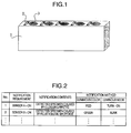
- Fig. 1 is a perspective view showing a specimen rack to be provided by the invention.
- a specimen rack 1 is of a rectangular solid shape, and includes a specimen container loading slot 3 to hold a cylindrical shaped specimen container, a luminous body 2 (for example, LEDs (light-emitting diode), a display constituted by an organic EL or liquid crystal) corresponding to each of the specimen container loading slots 3.
- the luminous body 2 having a single color or plural colors as a notification unit is disposed in a top portion of the specimen rack 1 and at a vicinity closer to the specimen container loading slot 3 corresponding to a specimen, as an example, compared with a specimen container loading slot 3 not corresponding to the specimen.
- the luminous body 2 may be disposed at a position above the top portion of the specimen rack 1. Note that the top portion means an upper surface of the specimen rack 1.
- a notification unit a notification by a sound (speaker etc.) or a vibration (oscillator etc.) may be used.
- Fig. 1 shows five specimen container loading slots 3 to hold five specimen containers, as held by the specimen rack 1.
- the number of specimen containers held by the specimen rack 1 is not limited to “five” as well as the number of specimen container loading slots 3, but may also be “one” or “ten” in the embodiment of the invention.
- the luminous body 2 may be disposed not only between the specimen container loading slots 3 and on the vicinity of the specimen container loading slots 3, but also on any positions where an operator can visually recognize correspondence to the respective specimens.
- the luminous body 2 may also be disposed on a side surface of the specimen rack 1 (desirably, a side surface close to the top face of the specimen rack 1 among other surfaces) or in the specimen container loading slot 3 so that a luminous ray is transmitted through the side surface of the specimen rack 1.
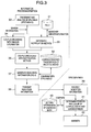
- Fig. 2 is an example of a correspondence table showing a notification requirement, notification contents, and a notification method including a color of the luminous body and a luminous mode.
- a sensor A for detecting a clogging pipette which sucks a specimen is actuated as on-state, as an abnormality in a treatment and analysis operation, a result of detecting the clogging pipette is notified to outside (operator, for example) by the luminous color "red" of the luminous body 2 and the luminous mode "turned ON".
- the luminous color of the luminous body 2 and luminous mode can be determined as the notification method of notification means, when sensor information meets the notification requirement.
- the abnormality may be indicated by a single color and a single luminous mode.
- Fig. 3 is a flow chart showing steps from a specimen treatment and analysis to a performance of notification by the notification unit.
- An analyzing device and pretreatment device have an information processing portion (for example, CPU) and a storage unit for storing programs, a database and a table.
- the specimen rack 2 also has an information processing portion (for example, microcomputer) and a storage unit for storing programs, a database and a table.
- the information processing portion in the analyzing device or pretreatment device allots a specimen ID for identifying a target specimen to be subjected to the treatment and analysis to the specimen held on the specimen container.
- the storage unit of the analyzing device and pretreatment device stores the correspondence table shown in Fig. 2 .
- the treatment and analysis are performed for the specimen having the specimen ID (step 33).
- the information processing portion in the analyzing device or pretreatment device receives sensor information indicating the abnormality
- the information processing portion couples the sensor information to the specimen ID (step 34).
- the specimen ID and sensor information are stored in the storage unit to correspond in one to one relation, so that the sensor information can be coupled to the specimen ID.
- the information processing portion in the analyzing device or pretreatment device uses the correspondence table shown in Fig. 2 (step 31) to search the notification method (luminous color and luminous type) on the basis of the sensor information (step 35).
- the information processing portion in the analyzing device or pretreatment device then couples the notification method to the specimen ID (step 36).
- a rack ID is also allotted to each of the specimen racks 1 in advance to identify them, and the storage unit (for example, barcode, IC chip or EEPROM) contained in the respective specimen racks 1 holds the respective rack IDs.
- the information processing portion in the analyzing device or pretreatment device Prior to the treatment and analysis, the information processing portion in the analyzing device or pretreatment device generates a correspondence table (step 32) indicating correspondence between rack IDs and specimen IDs such that which specimen is held on which of the specimen rack 1 and which of the specimen container loading slot 3, on the basis of ID information, such as a barcode applied to the specimen racks 1 and specimen containers, and stores the correspondence table in the storage unit of the analyzing device or pretreatment device.
- the information processing portion conducts collation to determine that the specimen having the specimen ID of interest is held in which of the specimen rack 1 and in which of the specimen container loading slot 3, on the basis of the correspondence table (step 32), so that the rack ID that holds the specimen of interest is identified and indication (instruction) information is then generated to indicate as to which of the luminous bodies 2 in the specimen rack 1 is turned on in which color or is to blink (step 37), and the indication information is transmitted to the specimen rack 1 (step 38).
- Fig. 4 is a table showing the indication information in the case where the number of specimen container loading slots 3 on the specimen rack 1 is "five.”
- specimen IDs are associated with respective rack IDs of the specimen racks 1 and with positions of specimen container loading slots 3 of the respective specimen racks. Further, corresponding notification methods (luminous color and luminous mode) are also associated therewith.
- the indication information determined by the foregoing steps is transmitted from the communication unit in the specimen carrier system to the communication unit on the specimen rack 1 (step 39).
- the indication information is transmitted from the communication unit in the specimen carrier system to the communication unit on the specimen rack 1 such that, when the specimen rack 1 moves from the units for performing the specimen treatment and analysis up to the unloading position in the specimen carrier system on a carrier line and upon passing through the vicinity of the communication unit in the specimen carrier system, the rack ID on the specimen rack 1 and specimen ID are read by using the respective communication units in the specimen rack and specimen carrier system so that when the passing specimen rack 1 which holds an abnormally detected specimen is recognized, the indication information is transmitted from the communication unit in the specimen carrier system to the communication unit on the specimen rack 1.
- the indication information is broadcasted from the communication unit provided in the unloading position to the communication units in the respective specimen racks 1 aligned in the unloading position so that the rack ID and specimen ID are compared both on the specimen carrier system side and on the specimen rack side so that the specimen rack having the corresponding ID receives the indication information.
- the specimen rack 1 requires that information concerning the specimen ID of the specimen held thereon and the position on the specimen rack 1 is stored temporarily in the storage unit. The information is transmitted from the communication unit in the specimen carrier system to the communication unit on the specimen rack 1.
- a time period from when the ID such as barcode on the specimen rack 1 or specimen container is read to a time before the treatment and analysis are performed is desirable. Further, it is necessary to judge correctly a transmission destination of the indication information not only by the rack ID, but also a combination with the specimen ID which does not allow the same ID basically, since it is likely that the specimen rack 1 having the same rack ID are present in plural numbers on one specimen carrier system and pretreatment device and analyzing device.
- the storage unit on the specimen rack 1 stores setting information (step 40) as read-only information, in advance, concerning a number representing a position of the specimen container loading slot 3 on the specimen rack 1 and the type of luminous color to be emitted and the luminous mode, in respect of the luminous body provided on the specimen rack 1 itself.
- the information processing portion in the specimen rack 1 compares the setting information (step 40) with the received indication information ( Fig. 4 ) so that the position of luminous body 2 to be emitted, luminous color and luminous mode are determined (step 41) to emit light from the luminous body 2 (step 42). After receiving the indication information, it is possible to turn the corresponding luminous body 2 on or to blink any time, on the basis of the indication information.
- a time period of emitting light from the luminous body 2 is from a start time to an end time for working on distinguishing the plural specimens aligned in the unloading position of the specimen rack 1 by the operator.
- a start signal and an end signal may be transmitted from the analyzing unit (device) or pretreatment unit (device) to the specimen rack 1 to control the start and end of emitting the light from the luminous body 2 in accordance with an indication by the operator who operates a console or an operational screen that are part of the specimen carrier system, analyzing device and pretreatment device.
- a sensor or switch may be provided on the specimen rack 1 or a carrier rail for carrying the specimen rack 1 or a structure near the carrier rail in advance so that it detects the specimen rack 1 arriving at a predetermined position (position where the operator works to distinguish the specimens during a time period from the start time to the end time) on the carrier rail and, using the detected signal of the sensor or switch as a trigger, the specimen rack 1 itself may control the start and end of the light emission from the luminous body 2 or, in response to the start signal and end signal transmitted to the specimen rack 1 from the analyzing unit or pretreatment unit, the specimen rack 1 may control the start and end of emitting light from the luminous body 2.
- An electric feeding unit for example, supply electrode
- An electric feeding unit to the specimen rack 1 may be provided on a predetermined position alone where the specimen rack 1 is present (position where the operator works to distinguish the specimens during a time period from the start time to the end time) on the carrier rail. Consequently, the specimen rack 1 receives an electric power to operate itself only when the specimen rack 1 exists at the predetermined position on the carrier rail.
- the notification contents are not limited to the information, such as a clogging pipette and specimen's fluid volume shortage necessary for a distinguishing at the unloading position for use in the treatment and analysis again, that are information on the specimen condition and progress in analyzing of specimens on the treatment and analysis, detected by the sensors provided in the pretreatment device and analyzing device.
- the notification requirement for performing the notification unit the notification contents to be notified to outside and the luminous color and luminous mode of the luminous body 2 are associated with each other in advance.
- the condition that all of the sensors on the devices are not actuated may be made the notification requirement so that the luminous body 2 may emit light to notify that the specimens are normal for which all of the necessary treatment and analysis have normally completed.
- the condition that information erasure is completed normally when temporarily stored information in the storage unit on the specimen rack 1 is reset may be made the notification condition so that the luminous body 2 may emit light to notify a completion of the reset.
- a time period for notifying that a specimen is normal is preferably, but not limited to, a time period from the start to the end of the distinguishing work by the operator for explicit distinction over a specimen that is detected by the sensors due to the clogging pipette and fluid volume shortage.
- the notification indicating the completion of reset may possibly be made by emitting the luminous body for a certain emission time period from a time point of erasing the information from the storage unit in the specimen rack 1 by the operator.
- Fig. 5 is an explanatory diagram showing that the specimen racks 1 in Fig. 1 are aligned in lateral direction perpendicular to a visual line of the operator in the unloading position of the specimen racks 1.
- the luminous body 2 is disposed on the left side of specimen container loading slot 3 in relation to the visual line direction of the operator.
- the luminous body 2 may be disposed on a location where the operator can recognize visually, for example, the right side of specimen container loading slot 3 or near side to the operator in relation to the visual line direction of the operator, except for a portion 4 which is hidden behind the specimen container in relation to the visual line direction of the operator.
- the luminous body 2 is not hidden behind the adjacent specimen rack 1 and the specimen container, in the case of the luminous body 2 disposed as shown in Fig. 1 . Therefore, the operator can easily recognize the emission of luminous body 2 and identify a corresponding relation between the luminous body 2 and the specimen.
- an optimum requirement for the location where the luminous body 2 is disposed on the specimen rack 1 is such that, taking into account of a position or posture of the specimen rack 1 and a direction of the specimen rack 1 in relation to the visual direction of the operator at the time of luminous emission, and the state of overlapping with adjacent specimen racks 1, specimen containers and a casing portion of the specimen carrier system, it is desirable that the luminous emission of the luminous body 2 can be recognized and a correspondence relation between the luminous body 2 and specimen can be identified without being hampered.
- the unloading position may be either separated from the input portion or the same position thereof, depending on the constitution of the specimen carrier system, analyzing device and pretreatment device.
- a luminous body constituted of a combination of a plural colors is correspondingly disposed on each of the specimens, so that notification information amount can be increased by the number of color combinations.
- the combined color luminous body 2 is turned on or to blink alternately, so that the notification information amount can be increased.
- the combination of luminous colors should be considered taking the foregoing possibility into account.
- Fig. 6 is a block diagram showing the specimen rack 1 constituted by a notification unit 65 and a communication unit 64 and a control unit 61 and a storage unit 62 for executing the operation of the notification unit 65 and communication unit 64.
- the specimen rack 1 receives an electric power from a power supply unit 63.
- the control unit 61 makes a correspondence relation of a specimen ID, a position of the luminous body 2, a luminous color and a luminous emission mode, contained in the indication information, and emits light from the luminous body 2 specified by the rack ID and the position of specimen container loading slot 3 in accordance with the correspondence relation to control the notification unit 65, on the basis of the indication information ( Fig. 4 , for example) obtained from outside (for example, analyzing device or pretreatment device) through the communication unit 64 and programs stored in the storage unit 62. Information to be temporarily saved is stored in the storage unit 62, among pieces of information obtained from outside.
- the storage unit 62 may be used desirably of an existing storage unit in response to information contents to be stored and an application form, for example, a ROM (Read Only Memory) used for information unnecessary for a rewriting such as a control program, and a RAM (Random Access Memory) used for saving information necessary for a sequential rewriting such that which of a luminous body 2 on the specimen rack 1 is emitted by what a color of emission, and for temporarily saving information, etc.
- ROM Read Only Memory
- RAM Random Access Memory
- the temporarily stored information in the RAM can be made disappeared upon cutting off of the power supply to the specimen rack 1 (particularly, storage unit).
- the temporarily stored information can be deleted sequentially in response to an instruction from the operation of the console, the button on the operational screen, and the switch, provided in the pretreatment device and analyzing device, or the operation of an information processing device such as a personal computer communicating with the pretreatment device and analyzing device, by using communication units provided in the specimen rack 1 and specimen carrier system or the temporarily stored information can be deleted by conducting an operation for information deletion such that a reset button provided on the specimen rack 1 is depressed.
- the temporarily stored information may also be deleted arbitrarily and automatically in accordance with a predetermined requirement and a predetermined logic in the specimen carrier system, analyzing device and pretreatment device, or a specimen rack installing facility independent from the foregoing system and units (devices), without instruction from the operator.
- the electric power necessary for performing the foregoing units such as the notification unit 65 and communication unit 64 is supplied from the power supply unit 63.
- the power supply unit 63 may not be required to supply the electric power to the communication unit 64.
- the notification unit 65 is constituted of a LED-integrated type RFID including the control unit 61, storage unit 62 and communication unit 64, connected with the communication unit 65 and by adapting the LED-integrated type RFID to be controlled by the analyzing device or pretreatment device in such a way that the LED emits light when a RFID-destination signal is received only from the analyzing device or pretreatment device, it becomes not necessary to provide wiring among the control unit, storage unit and power supply unit 63, other than the LED-integrated type RFID.
- the foregoing units are fabricated in the specimen rack 1 in a certain size and shape which are allowed to downsize the specimen rack 1, because of little mounting space for the pretreatment device and analyzing device to which the specimen rack 1 are carried, and the input portion, the carrier rail and the unloading position in the specimen carrier system.
- the LED capable of emitting light by a small size and low electric power to the notification unit 65 enables not only the notification unit 65 to make downsized, but also the power supply portion to make downsized, therefore, the specimen rack 1 provided by the invention is used preferably for the pretreatment and analysis.
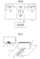
- Fig. 7 is a view showing an embodiment of the power supply unit 63 in connection with the specimen rack 1 and housing (repository) portion 9. Electric power is supplied from the specimen carrier system to the specimen rack 1 in a contact manner.
- Supplying electrodes 10, 12 are formed on a carrier rail 11 (or a specimen rack installing rail) which is disposed on the unloading position 9 (or input portion or specimen rack installing facility) for the purpose of safety against overturning and fixing a movement route for the specimen rack 1 in the unloading position 9.
- Receiving electrodes 6, 8 are formed in a groove portion 7 on a bottom surface 5. The groove portion 7 is disposed in the bottom surface 5 of the specimen rack 1 so that the specimen rack 1 carried on the carrier rail 11 can move in the unloading position 9.
- the receiving electrodes 6 and 8 in the groove 7 of the specimen rack 1 are so disposed that they correspond to the supplying electrodes 10 and 12 on the carrier rail 11 of the specimen carrier system, respectively.
- the specimen rack 1 may have an accumulator unit (not shown) for accumulating electric power supplied from the specimen carrier system or a battery charger (not shown). In the case where the accumulator unit is not used for receiving electric power the electric power and supplying it to the notification unit 65 and communication unit 64 in the specimen rack 1, it is necessary to provide a dry battery or fuel battery as a power source in the specimen rack 1 to supply electric power to the notification unit 65 and communication unit 64.
- a communication unit used for communicating the information necessary for the control and a power receiving and supplying unit for performing the notification unit provided in the specimen rack 1 may be provided in the move destination, or the main body of specimen carrier system is provided in the move destination, as required, so that similar advantages can be obtained from the condition either before or after the unloading position 9 is removed, even though the move destination after moved the unloading position 9 is independent from the specimen carrier system.
- the unit used for communicating information necessary for the control and the power receiving and supplying unit for performing the notification unit provided in the specimen rack 1 are provided for the specimen rack installing facility, specimen rack 1, or the main body of specimen carrier system, similarly to the foregoing removable unloading position 9 from the specimen carrier system, so that the foregoing similar advantages can be obtained from the condition either before or after the unloading position 9 is removed.
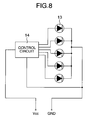
- Fig. 8 is a circuit diagram showing the notification unit 65 using LEDs 13, in which the notification unit 65 is connected with the receiving electrodes 6, 8 formed with the groove portion 7 on the specimen rack 1 as shown in Fig. 7 .
- a control circuit 14 contains a resistor and capacitor used for a current regulation relative to the LEDs 13, and also contains a microcomputer corresponding to the control unit 61.
- the circuit shown in Fig. 8 corresponds to using five LEDs 13 corresponding to the five specimen container loading slots 3.
- a plurality of LEDs 13 may be corresponded to each of the specimen container loading slots 3, and the power supply unit to the LEDs 13 may be replaced with other types.
- the specimen rack and specimen carrier system provided by the invention are used in hospitals, inspection centers, specimen laboratories, etc., where a number of specimens are handled, to provide requirements for reliability of the analysis and treatment operations, high throughput, low cost, etc. Competitors have developed and sold the specimen rack and specimen carrier system.
- the LED described in the embodiment as the notification unit of the specimen rack 1 can be mounted on the presently and widely available specimen rack having a certain size, and produced by the competitors because such LED can emit light by a small size and low power consumption. Further, it is possible to select colors corresponding to the notification contents because there are plural colors (red, yellow, blue, green and white). It is also possible to produce the specimen rack and specimen carrier system in mass production, low price, and long life, which is one of advantages.
- the communication unit used for the specimen rack and specimen carrier system has advanced in low cost and high technology with an ID tag such as information readable and writable RFID by a radio wave, therefore, the increase of employing the RFID is promised in place of the barcode which is presently and widely used as an ID to be applied to the specimen rack 1. It is thus possible to promise use of products developed by the present invention.
Abstract
Description
- The present invention relates to a specimen rack and a specimen carrier system in which the specimen rack holds simultaneously a single or plurality of specimen containers containing specimens, for use in a pretreatment device and an analyzing device to treat (process) or analyze specimen samples such as bloods and urines, and the specimen carrier system is furnished inside or outside an apparatus which carries the specimen rack to the pretreatment device and analyzing device.
- The pretreatment device and analyzing device have been grown in size with increase of test items and the number of specimens to perform a necessary treatment given to a specimen and to analyze it automatically for the specimen analysis. Meanwhile, to make a test work more efficient, the devices have been demanded for an enhancement of reliability, high throughput and low cost. For a purpose of enhancing a treatment performance, a specimen carrier system has been developed and commercially usable with use of coupling a plurality of devices, and the specimens are then carried by straddling the devices. A specimen rack has also been developed and commercially usable to be able to carry the plural specimens simultaneously.
- The specimens held in the specimen rack are carried from an input portion of the specimen carrier system to the pretreatment device and analyzing device, and carried to an unloading position of the specimen carrier system, after the necessary treatment and analysis are completed. A pipette for sucking the specimen is sometimes clogged with a coagulation in the specimen on the treatment and analysis, depending on a quantity or condition of the specimen. In addition, an abnormality sometimes occurs such that a specimen fluid volume is short for the number of test items to analyze it. When the abnormality is detected, the devices judge a specimen condition from sensor information to immediately cease the analyzing operation for an abnormal specimen and to move to the analyzing operation for the next specimen. The abnormal specimen caused by the clogging and fluid volume shortage is applied again by the pretreatment and the like, and the abnormal specimen is repeatedly subject to the analysis.
- In the case of a large size device, several tens to over hundreds specimen racks are carried by a carrier device, therefore, the total number of specimens on the carrier device could be several hundreds, depending on the number of specimens held by the specimen rack. In order to automatically and accurately associate each of such a great number specimens with analysis item and progress of analysis for the specimen and result of analysis, an ID such as a barcode is not only applied to a specimen container to read it reliably, but also applied to the specimen rack, as disclosed in
JP-A-2-253854 JP-A-11-83865 - However, after completing the successive treatment and analysis, it is necessary to compare an ID of a specimen to be classified and its position on an unloading position with displayed information on a monitor screen of an accessorius personal computer which the device come with and sheets printed separately so that the normally treated and analyzed specimen and the abnormally detected specimen caused by the clogging, fluid volume shortage and so forth are distinguished among the specimens aligned in the unloading position, for a purpose of classifying the specimens. A number of specimen containers and specimen racks that look alike are aligned in the unloading position. For this reason, in the case where the number of specimens is several hundreds, the work for judging and distinguishing and extracting the abnormal specimen while comparing it with the monitor screen and the printings of sheets is not only complicated and inefficient, but also possibly arouses an artificial mistake such as a switched specimen. For this reason, it is necessary to have a technique such that information is given to the specimen or specimen rack to transmit the information from the specimen or specimen rack, as required. However, the foregoing background techniques fail to provide a fundamental solution to the foregoing problem since they require an intervention of a certain information device such as a personal computer or mobile telephone to communicate with the device or the printed sheets for obtaining the information transmitted from the specimen or specimen rack.
- An object of the invention is to provide a specimen rack and specimen carrier system capable of distinguishing and classifying conditions and positions of the target specimens without need to compare them with other information media by an operator by directly notifying outside of the analyzing situation and the specimen condition for each of the specimens aligned in the unloading position by using visual and intuitive means from the specimen rack.
- In order to achieve the foregoing object, the present invention is constituted by the following constitutions.
- A specimen rack that can hold simultaneously a single or plural specimen containers (normally, a test tube shape, but not limited to it), and have a notification unit that notifies, to outside, information concerning analysis situation and specimen condition for specimens each held on the specimen containers, and a communication unit that transmits and receives information necessary for a performance of the notification unit to and from outside. And, a specimen carrier system that carries the specimens to a pretreatment device that performs pretreatment for specimen analysis and to an analyzing device that analyzes the specimens, and have a communication unit that transmits and receives information to and from the specimen rack necessary for performing the notification unit.
- A luminous body having a single or plural colors may be used for the notification unit of the specimen rack. The luminous body may be disposed on a top portion of the specimen rack or a portion above the top portion of the specimen rack. Alternatively, for a purpose of recognizing easily a correspondence between the luminous body and specimen, the luminous body may be disposed on a vicinity of a specimen container loading slot of the corresponding specimen, compared with a specimen container loading slot of a specimen which does not correspond to the specimen. By combining the colors of predetermined luminous body corresponding to the specimen, the amount of information notified to outside can be increased for the analysis situation and specimen condition for the specimen held on the single or plural specimen containers.
- As a unit for receiving and supplying electric power necessary for the performance of the notification unit and communication unit in the specimen rack, a supply unit may be provided to supply electric power from the specimen carrier system to the specimen rack in a contact or non-contact manner. The specimen rack may have an accumulating unit to accumulate electric power supplied from the specimen carrier system or a battery charger. A supply unit may be provided at an input portion and/or the unloading position in the specimen carrier system to supply electric power to the specimen rack. In this case, a receiving unit is necessary for the specimen rack to receive electric power from the power supply unit provided in the input portion and/or the unloading position. In addition, in the case where the foregoing units are not relied to receive and supply the electric power necessary for performing the notification unit and communication unit of the specimen rack, the specimen rack should have an own power source to supply electric power for performing the notification unit and communication unit of the specimen rack.
- As to the communication unit to communicate between the specimen rack and specimen carrier system, a transmission/reception unit for transmitting and receiving information necessary for the notification may be provided in the input portion and/or the unloading position by the contact or non-contact condition. A communication unit for transmitting and receiving the information to and from the communication unit provided in the input portion and/or the storage unit is provided in the specimen rack.
- As a unit for storing information necessary for performing and controlling the notification unit provided in the specimen rack, the specimen rack is provided with a storage unit that temporarily stores all or part of information obtained from a communication with outside, and a storage unit that semi-permanently stores read-only information unnecessary for rewritten and erasure.
- Particularly, the information, such as analysis situation and specimen condition for each of the specimens held on the specimen rack, that is temporarily stored in the storage unit of the specimen rack, can be erased by operating a button or a switch that is provided on the specimen rack or specimen carrier system or provided on a console or a operation screen which is a part of or is provided separately of the analyzing device or pretreatment device connected with the specimen carrier system.
- Further, for the communication unit provided in the specimen rack to be able to operate as in the same way as it used to even after the input portion or the unloading position is removed from the main body of the specimen carrier system, the specimen rack or the input portion and/or the unloading position is provided with a communication unit that communicates by a wire or wireless system with the specimen carrier system or with a communication unit provided in a move destination of the input portion or unloading position. Further, the specimen rack or the input portion and/or the unloading position is provided with a unit for receiving electric power, by a wire or wireless system, necessary for performing and controlling the notification unit provided in the specimen rack from the main body of specimen carrier system or a power supply unit provided in the move destination of the input portion or unloading position after removed from the specimen carrier system.
- With the foregoing constitution of the invention, the analyzing situation and the specimen condition for a number of specimens aligned in the unloading position are notified directly to outside by visual and intuitive means from the specimen rack in which the specimens are held, so that it is possible to distinguish and classify the target specimen conditions and their positions of abnormally detected specimens, without comparing, by an operator, the monitor screen of the personal computer physically remote from the unloading position and the printed-out matters of information media such as printing sheets.
- As a result, not only a work efficiency of the operator is improved, but also advantages can be expected such that a possibility for an artificial mistake such as a switched specimen is reduced. Further, reliability, work efficiency and economical efficiency for the test work can be enhanced in a facility in which the pretreatment device and analyzing device are operated.
- The other objects, features and advantages of the invention will become apparent from the following description of the embodiments of the invention taken in conjunction with the accompanying drawings.
-
-
Fig. 1 is a perspective view showing a specimen rack provided by the invention; -
Fig. 2 is an explanatory diagram showing an example of a notification requirement, notification contents and a notification method; -
Fig. 3 is a flow chart showing steps from a treatment and analysis to a performance of a notification unit; -
Fig. 4 is an explanatory diagram showing an example of indication information; -
Fig. 5 is a plan view showing the specimen racks aligned in an unloading position; -
Fig. 6 is a block diagram showing units to be mounted on the specimen rack; -
Fig. 7 is perspective views showing an example of a power receiving and supplying unit mounted on the specimen rack and specimen carrier system; and -
Fig. 8 is a circuit diagram showing an example of a wiring from the power receiving and supplying unit to a notification unit. - Hereinafter, embodiments of the invention will be described with reference to the drawings.
-
Fig. 1 is a perspective view showing a specimen rack to be provided by the invention. Aspecimen rack 1 is of a rectangular solid shape, and includes a specimencontainer loading slot 3 to hold a cylindrical shaped specimen container, a luminous body 2 (for example, LEDs (light-emitting diode), a display constituted by an organic EL or liquid crystal) corresponding to each of the specimencontainer loading slots 3. In thespecimen rack 1 according to the embodiment, theluminous body 2 having a single color or plural colors as a notification unit is disposed in a top portion of thespecimen rack 1 and at a vicinity closer to the specimencontainer loading slot 3 corresponding to a specimen, as an example, compared with a specimencontainer loading slot 3 not corresponding to the specimen. Theluminous body 2 may be disposed at a position above the top portion of thespecimen rack 1. Note that the top portion means an upper surface of thespecimen rack 1. As the notification unit, a notification by a sound (speaker etc.) or a vibration (oscillator etc.) may be used. -
Fig. 1 shows five specimencontainer loading slots 3 to hold five specimen containers, as held by thespecimen rack 1. The number of specimen containers held by thespecimen rack 1 is not limited to "five" as well as the number of specimencontainer loading slots 3, but may also be "one" or "ten" in the embodiment of the invention. Further, theluminous body 2 may be disposed not only between the specimencontainer loading slots 3 and on the vicinity of the specimencontainer loading slots 3, but also on any positions where an operator can visually recognize correspondence to the respective specimens. However, in the case where theluminous body 2 is disposed on a position far apart from a corresponding specimen, it is likely that a visual recognition of correspondence between aluminous body 2 and corresponding specimen container is degraded, in comparison with the case where theluminous body 2 is disposed on the vicinity of specimencontainer loading slot 3. Further, theluminous body 2 may also be disposed on a side surface of the specimen rack 1 (desirably, a side surface close to the top face of thespecimen rack 1 among other surfaces) or in the specimencontainer loading slot 3 so that a luminous ray is transmitted through the side surface of thespecimen rack 1. -
Fig. 2 is an example of a correspondence table showing a notification requirement, notification contents, and a notification method including a color of the luminous body and a luminous mode. For example, when a sensor A for detecting a clogging pipette which sucks a specimen is actuated as on-state, as an abnormality in a treatment and analysis operation, a result of detecting the clogging pipette is notified to outside (operator, for example) by the luminous color "red" of theluminous body 2 and the luminous mode "turned ON". Similarly, when a sensor B for detecting a fluid volume shortage is actuated as on-state, the fluid volume shortage is notified to outside by the luminous color "green" ofluminous body 2 and the luminous mode "blink". By using the correspondence table shown inFig. 2 , the luminous color of theluminous body 2 and luminous mode can be determined as the notification method of notification means, when sensor information meets the notification requirement. Alternatively, only the abnormality may be indicated by a single color and a single luminous mode. -
Fig. 3 is a flow chart showing steps from a specimen treatment and analysis to a performance of notification by the notification unit. An analyzing device and pretreatment device have an information processing portion (for example, CPU) and a storage unit for storing programs, a database and a table. Thespecimen rack 2 also has an information processing portion (for example, microcomputer) and a storage unit for storing programs, a database and a table. - The information processing portion in the analyzing device or pretreatment device allots a specimen ID for identifying a target specimen to be subjected to the treatment and analysis to the specimen held on the specimen container. The storage unit of the analyzing device and pretreatment device stores the correspondence table shown in
Fig. 2 . - The treatment and analysis are performed for the specimen having the specimen ID (step 33). When an abnormality is detected by the sensor, and the information processing portion in the analyzing device or pretreatment device receives sensor information indicating the abnormality, the information processing portion couples the sensor information to the specimen ID (step 34). For example, the specimen ID and sensor information are stored in the storage unit to correspond in one to one relation, so that the sensor information can be coupled to the specimen ID. On the other hand, the information processing portion in the analyzing device or pretreatment device uses the correspondence table shown in
Fig. 2 (step 31) to search the notification method (luminous color and luminous type) on the basis of the sensor information (step 35). The information processing portion in the analyzing device or pretreatment device then couples the notification method to the specimen ID (step 36). As a result of the foregoing steps, it becomes possible to determine which notification method is to be performed for the specimen having the specimen ID. - A rack ID is also allotted to each of the specimen racks 1 in advance to identify them, and the storage unit (for example, barcode, IC chip or EEPROM) contained in the
respective specimen racks 1 holds the respective rack IDs. Prior to the treatment and analysis, the information processing portion in the analyzing device or pretreatment device generates a correspondence table (step 32) indicating correspondence between rack IDs and specimen IDs such that which specimen is held on which of thespecimen rack 1 and which of the specimencontainer loading slot 3, on the basis of ID information, such as a barcode applied to the specimen racks 1 and specimen containers, and stores the correspondence table in the storage unit of the analyzing device or pretreatment device. The information processing portion conducts collation to determine that the specimen having the specimen ID of interest is held in which of thespecimen rack 1 and in which of the specimencontainer loading slot 3, on the basis of the correspondence table (step 32), so that the rack ID that holds the specimen of interest is identified and indication (instruction) information is then generated to indicate as to which of theluminous bodies 2 in thespecimen rack 1 is turned on in which color or is to blink (step 37), and the indication information is transmitted to the specimen rack 1 (step 38). -
Fig. 4 is a table showing the indication information in the case where the number of specimencontainer loading slots 3 on thespecimen rack 1 is "five." Referring toFig. 4 , specimen IDs are associated with respective rack IDs of the specimen racks 1 and with positions of specimencontainer loading slots 3 of the respective specimen racks. Further, corresponding notification methods (luminous color and luminous mode) are also associated therewith. - The indication information determined by the foregoing steps is transmitted from the communication unit in the specimen carrier system to the communication unit on the specimen rack 1 (step 39). In a possible transmission method in this case, the indication information is transmitted from the communication unit in the specimen carrier system to the communication unit on the
specimen rack 1 such that, when thespecimen rack 1 moves from the units for performing the specimen treatment and analysis up to the unloading position in the specimen carrier system on a carrier line and upon passing through the vicinity of the communication unit in the specimen carrier system, the rack ID on thespecimen rack 1 and specimen ID are read by using the respective communication units in the specimen rack and specimen carrier system so that when the passingspecimen rack 1 which holds an abnormally detected specimen is recognized, the indication information is transmitted from the communication unit in the specimen carrier system to the communication unit on thespecimen rack 1. Alternatively, when the maximum accommodation number ofspecimen racks 1 or a certain number thereof are carried at the unloading position, or the operator indicates a transmission to thespecimen rack 1, the indication information is broadcasted from the communication unit provided in the unloading position to the communication units in therespective specimen racks 1 aligned in the unloading position so that the rack ID and specimen ID are compared both on the specimen carrier system side and on the specimen rack side so that the specimen rack having the corresponding ID receives the indication information. To this end, thespecimen rack 1 requires that information concerning the specimen ID of the specimen held thereon and the position on thespecimen rack 1 is stored temporarily in the storage unit. The information is transmitted from the communication unit in the specimen carrier system to the communication unit on thespecimen rack 1. As the time period of the transmission and reception, a time period from when the ID such as barcode on thespecimen rack 1 or specimen container is read to a time before the treatment and analysis are performed, is desirable. Further, it is necessary to judge correctly a transmission destination of the indication information not only by the rack ID, but also a combination with the specimen ID which does not allow the same ID basically, since it is likely that thespecimen rack 1 having the same rack ID are present in plural numbers on one specimen carrier system and pretreatment device and analyzing device. - The storage unit on the
specimen rack 1 stores setting information (step 40) as read-only information, in advance, concerning a number representing a position of the specimencontainer loading slot 3 on thespecimen rack 1 and the type of luminous color to be emitted and the luminous mode, in respect of the luminous body provided on thespecimen rack 1 itself. The information processing portion in thespecimen rack 1 compares the setting information (step 40) with the received indication information (Fig. 4 ) so that the position ofluminous body 2 to be emitted, luminous color and luminous mode are determined (step 41) to emit light from the luminous body 2 (step 42). After receiving the indication information, it is possible to turn the correspondingluminous body 2 on or to blink any time, on the basis of the indication information. However, it is desirable that a time period of emitting light from theluminous body 2 is from a start time to an end time for working on distinguishing the plural specimens aligned in the unloading position of thespecimen rack 1 by the operator. For this reason, a start signal and an end signal may be transmitted from the analyzing unit (device) or pretreatment unit (device) to thespecimen rack 1 to control the start and end of emitting the light from theluminous body 2 in accordance with an indication by the operator who operates a console or an operational screen that are part of the specimen carrier system, analyzing device and pretreatment device. Further, a sensor or switch may be provided on thespecimen rack 1 or a carrier rail for carrying thespecimen rack 1 or a structure near the carrier rail in advance so that it detects thespecimen rack 1 arriving at a predetermined position (position where the operator works to distinguish the specimens during a time period from the start time to the end time) on the carrier rail and, using the detected signal of the sensor or switch as a trigger, thespecimen rack 1 itself may control the start and end of the light emission from theluminous body 2 or, in response to the start signal and end signal transmitted to thespecimen rack 1 from the analyzing unit or pretreatment unit, thespecimen rack 1 may control the start and end of emitting light from theluminous body 2. An electric feeding unit (for example, supply electrode) to thespecimen rack 1 may be provided on a predetermined position alone where thespecimen rack 1 is present (position where the operator works to distinguish the specimens during a time period from the start time to the end time) on the carrier rail. Consequently, thespecimen rack 1 receives an electric power to operate itself only when thespecimen rack 1 exists at the predetermined position on the carrier rail. - In addition, the notification contents are not limited to the information, such as a clogging pipette and specimen's fluid volume shortage necessary for a distinguishing at the unloading position for use in the treatment and analysis again, that are information on the specimen condition and progress in analyzing of specimens on the treatment and analysis, detected by the sensors provided in the pretreatment device and analyzing device. As indicated by
Fig. 2 , it suffices that the notification requirement for performing the notification unit, the notification contents to be notified to outside and the luminous color and luminous mode of theluminous body 2 are associated with each other in advance. For example, the condition that all of the sensors on the devices are not actuated may be made the notification requirement so that theluminous body 2 may emit light to notify that the specimens are normal for which all of the necessary treatment and analysis have normally completed. For another example, the condition that information erasure is completed normally when temporarily stored information in the storage unit on thespecimen rack 1 is reset may be made the notification condition so that theluminous body 2 may emit light to notify a completion of the reset. A time period for notifying that a specimen is normal is preferably, but not limited to, a time period from the start to the end of the distinguishing work by the operator for explicit distinction over a specimen that is detected by the sensors due to the clogging pipette and fluid volume shortage. Further, the notification indicating the completion of reset may possibly be made by emitting the luminous body for a certain emission time period from a time point of erasing the information from the storage unit in thespecimen rack 1 by the operator. -
Fig. 5 is an explanatory diagram showing that the specimen racks 1 inFig. 1 are aligned in lateral direction perpendicular to a visual line of the operator in the unloading position of the specimen racks 1. Referring toFig. 5 , there are 12consecutive specimen racks 1, each of which can hold five specimen containers. Theluminous body 2 is disposed on the left side of specimencontainer loading slot 3 in relation to the visual line direction of the operator. Theluminous body 2 may be disposed on a location where the operator can recognize visually, for example, the right side of specimencontainer loading slot 3 or near side to the operator in relation to the visual line direction of the operator, except for aportion 4 which is hidden behind the specimen container in relation to the visual line direction of the operator. - In a housing or reposition method shown in
Fig. 5 , theluminous body 2 is not hidden behind theadjacent specimen rack 1 and the specimen container, in the case of theluminous body 2 disposed as shown inFig. 1 . Therefore, the operator can easily recognize the emission ofluminous body 2 and identify a corresponding relation between theluminous body 2 and the specimen. In this way, an optimum requirement for the location where theluminous body 2 is disposed on thespecimen rack 1 is such that, taking into account of a position or posture of thespecimen rack 1 and a direction of thespecimen rack 1 in relation to the visual direction of the operator at the time of luminous emission, and the state of overlapping withadjacent specimen racks 1, specimen containers and a casing portion of the specimen carrier system, it is desirable that the luminous emission of theluminous body 2 can be recognized and a correspondence relation between theluminous body 2 and specimen can be identified without being hampered. - In the embodiment of the invention, the unloading position may be either separated from the input portion or the same position thereof, depending on the constitution of the specimen carrier system, analyzing device and pretreatment device.
- Under the foregoing requirements, a luminous body constituted of a combination of a plural colors is correspondingly disposed on each of the specimens, so that notification information amount can be increased by the number of color combinations. For example, the combination of 4 x 4 = 16 kinds can be notified as the notification information amount if a luminous body having four colors is combined by two. Further, the combined color
luminous body 2 is turned on or to blink alternately, so that the notification information amount can be increased. However, depending on a combination of luminous colors, it may become difficult to distinguish each of the same combined colors, undesirably going against the intention according to the present invention of providing the visual and intuitive notification unit. Therefore, the combination of luminous colors should be considered taking the foregoing possibility into account. -
Fig. 6 is a block diagram showing thespecimen rack 1 constituted by anotification unit 65 and acommunication unit 64 and acontrol unit 61 and astorage unit 62 for executing the operation of thenotification unit 65 andcommunication unit 64. Thespecimen rack 1 receives an electric power from apower supply unit 63. - The
control unit 61 makes a correspondence relation of a specimen ID, a position of theluminous body 2, a luminous color and a luminous emission mode, contained in the indication information, and emits light from theluminous body 2 specified by the rack ID and the position of specimencontainer loading slot 3 in accordance with the correspondence relation to control thenotification unit 65, on the basis of the indication information (Fig. 4 , for example) obtained from outside (for example, analyzing device or pretreatment device) through thecommunication unit 64 and programs stored in thestorage unit 62. Information to be temporarily saved is stored in thestorage unit 62, among pieces of information obtained from outside. Thestorage unit 62 may be used desirably of an existing storage unit in response to information contents to be stored and an application form, for example, a ROM (Read Only Memory) used for information unnecessary for a rewriting such as a control program, and a RAM (Random Access Memory) used for saving information necessary for a sequential rewriting such that which of aluminous body 2 on thespecimen rack 1 is emitted by what a color of emission, and for temporarily saving information, etc. - The temporarily stored information in the RAM can be made disappeared upon cutting off of the power supply to the specimen rack 1 (particularly, storage unit). Alternatively, the temporarily stored information can be deleted sequentially in response to an instruction from the operation of the console, the button on the operational screen, and the switch, provided in the pretreatment device and analyzing device, or the operation of an information processing device such as a personal computer communicating with the pretreatment device and analyzing device, by using communication units provided in the
specimen rack 1 and specimen carrier system or the temporarily stored information can be deleted by conducting an operation for information deletion such that a reset button provided on thespecimen rack 1 is depressed. Alternatively, the temporarily stored information may also be deleted arbitrarily and automatically in accordance with a predetermined requirement and a predetermined logic in the specimen carrier system, analyzing device and pretreatment device, or a specimen rack installing facility independent from the foregoing system and units (devices), without instruction from the operator. - The electric power necessary for performing the foregoing units such as the
notification unit 65 andcommunication unit 64 is supplied from thepower supply unit 63. In this regard, in the case where thecommunication unit 64 is constituted of an ID tag such as a RFID (Radio Frequency Identification) having a built-in rectifier circuit, thepower supply unit 63 may not be required to supply the electric power to thecommunication unit 64. Further, when thenotification unit 65 is constituted of a LED-integrated type RFID including thecontrol unit 61,storage unit 62 andcommunication unit 64, connected with thecommunication unit 65 and by adapting the LED-integrated type RFID to be controlled by the analyzing device or pretreatment device in such a way that the LED emits light when a RFID-destination signal is received only from the analyzing device or pretreatment device, it becomes not necessary to provide wiring among the control unit, storage unit andpower supply unit 63, other than the LED-integrated type RFID. It is then desirable that the foregoing units are fabricated in thespecimen rack 1 in a certain size and shape which are allowed to downsize thespecimen rack 1, because of little mounting space for the pretreatment device and analyzing device to which thespecimen rack 1 are carried, and the input portion, the carrier rail and the unloading position in the specimen carrier system. For example, as shown inFig. 1 , using the LED capable of emitting light by a small size and low electric power to thenotification unit 65 enables not only thenotification unit 65 to make downsized, but also the power supply portion to make downsized, therefore, thespecimen rack 1 provided by the invention is used preferably for the pretreatment and analysis. -
Fig. 7 is a view showing an embodiment of thepower supply unit 63 in connection with thespecimen rack 1 and housing (repository)portion 9. Electric power is supplied from the specimen carrier system to thespecimen rack 1 in a contact manner. Supplyingelectrodes specimen rack 1 in theunloading position 9. Receivingelectrodes groove portion 7 on abottom surface 5. Thegroove portion 7 is disposed in thebottom surface 5 of thespecimen rack 1 so that thespecimen rack 1 carried on thecarrier rail 11 can move in theunloading position 9. - The receiving
electrodes groove 7 of thespecimen rack 1 are so disposed that they correspond to the supplyingelectrodes carrier rail 11 of the specimen carrier system, respectively. Thespecimen rack 1 may have an accumulator unit (not shown) for accumulating electric power supplied from the specimen carrier system or a battery charger (not shown). In the case where the accumulator unit is not used for receiving electric power the electric power and supplying it to thenotification unit 65 andcommunication unit 64 in thespecimen rack 1, it is necessary to provide a dry battery or fuel battery as a power source in thespecimen rack 1 to supply electric power to thenotification unit 65 andcommunication unit 64. - In the case where the
unloading position 9 shown inFig. 7 is removable from the main body of specimen carrier system, a communication unit used for communicating the information necessary for the control and a power receiving and supplying unit for performing the notification unit provided in thespecimen rack 1 may be provided in the move destination, or the main body of specimen carrier system is provided in the move destination, as required, so that similar advantages can be obtained from the condition either before or after theunloading position 9 is removed, even though the move destination after moved theunloading position 9 is independent from the specimen carrier system. - Further, even in the case where the
specimen rack 1 is placed separately in the specimen rack installing facility independent from the specimen carrier system, analyzing device, or pretreatment device, the unit used for communicating information necessary for the control and the power receiving and supplying unit for performing the notification unit provided in thespecimen rack 1 are provided for the specimen rack installing facility,specimen rack 1, or the main body of specimen carrier system, similarly to the foregoingremovable unloading position 9 from the specimen carrier system, so that the foregoing similar advantages can be obtained from the condition either before or after theunloading position 9 is removed. -
Fig. 8 is a circuit diagram showing thenotification unit 65 usingLEDs 13, in which thenotification unit 65 is connected with the receivingelectrodes groove portion 7 on thespecimen rack 1 as shown inFig. 7 . Acontrol circuit 14 contains a resistor and capacitor used for a current regulation relative to theLEDs 13, and also contains a microcomputer corresponding to thecontrol unit 61. The circuit shown inFig. 8 corresponds to using fiveLEDs 13 corresponding to the five specimencontainer loading slots 3. A plurality ofLEDs 13 may be corresponded to each of the specimencontainer loading slots 3, and the power supply unit to theLEDs 13 may be replaced with other types. - The specimen rack and specimen carrier system provided by the invention are used in hospitals, inspection centers, specimen laboratories, etc., where a number of specimens are handled, to provide requirements for reliability of the analysis and treatment operations, high throughput, low cost, etc. Competitors have developed and sold the specimen rack and specimen carrier system. The LED described in the embodiment as the notification unit of the
specimen rack 1 can be mounted on the presently and widely available specimen rack having a certain size, and produced by the competitors because such LED can emit light by a small size and low power consumption. Further, it is possible to select colors corresponding to the notification contents because there are plural colors (red, yellow, blue, green and white). It is also possible to produce the specimen rack and specimen carrier system in mass production, low price, and long life, which is one of advantages. On the other hand, the communication unit used for the specimen rack and specimen carrier system has advanced in low cost and high technology with an ID tag such as information readable and writable RFID by a radio wave, therefore, the increase of employing the RFID is promised in place of the barcode which is presently and widely used as an ID to be applied to thespecimen rack 1. It is thus possible to promise use of products developed by the present invention. - It should be further understood by those skilled in the art that although the foregoing description has been made on embodiments of the invention, the invention is not limited thereto and various changes and modifications may be made without departing from the spirit of the invention and the scope of the appended claims.
Claims (15)
- A specimen rack (1) that can hold a single or a plurality of specimen containers containing specimens, comprising:a notification unit (65) for notifying information, to outside, concerning an analyzing situation and a specimen condition for the specimen contained in the single or the plurality of specimen containers held on a specimen rack; anda communication unit (64) for transmitting and receiving information to and from outside, necessary for performing use of the notification unit.
- The specimen rack according to claim 1, wherein the notification unit (65) is constituted by a luminous body (2) having a single color or plural colors.
- The specimen rack according to claim 2, whereinthe luminous body (2) is disposed in a top portion or a position above the top portion, and/orthe luminous body (2) is disposed in the vicinity of a specimen container loading slot (3) corresponding to the specimen in comparison with the specimen container loading slot (3) which does not correspond to the specimen.
- The specimen rack according to claim 2, wherein the notification unit (65) is adapted to notify the analyzing situation and the specimen condition for the specimen contained in the single or the plural specimen containers held on the specimen rack by using a combination of colors of the luminous body (2), or an emission mode of the luminous body, or a combination of the colors of the luminous body and the emission mode of the color of luminous body, said combinations or emission mode being associated in advance with said the analyzing situation and the specimen condition for the specimen.
- The specimen rack according to any preceding claim, further comprisinga unit (6, 8, 10, 12) for receiving electric power in a contact or non-contact manner, and/ora unit for accumulating electric power, and/ora unit for receiving electric power from an electric power supplying unit (63) provided in an input portion and/or an unloading position of the specimen rack in a specimen carrier system.
- The specimen rack according to any preceding claim, wherein a unit for storing the information necessary for performing the use of and controlling the notification unit (65) includes a storage unit (62) for temporarily storing all or part of information obtained from communications with the outside unit and/or a storage unit for semi-permanently storing a read-only information requiring no rewriting or deletion.
- The specific rack according to claim 6, further comprising a unit for deleting the information stored temporarily in either one of or both of the storage units (62).
- The specific rack according to claim 7, wherein the deleting unit is adapted to delete the temporarily stored information in response to an operation by an operator who manipulates a button or a switch provided on a console or on an operation screen that are a part of or provided independently of the specimen rack, a specimen carrier system, a specimen analyzing device or a specimen analyzing pretreatment device.
- The specimen rack according to claim 1, wherein an input portion and an unloading position (9) that are removable from the specimen rack (1) or from a specimen carrier system includea communication unit for communicating in a wired or wireless manner with a communication unit provided in the specimen carrier system or in a move destination of the input portion and unloading position after removed from the specimen carrier system, and/ora unit for receiving electric power in a wired or wireless manner from the specimen carrier system or from an electric power supplying unit (63) provided in a move destination of the input portion and unloading position after being removed from the specimen carrier system.
- The specimen rack according to claim 1, wherein the specimen rack (1) is disposed in a specimen rack installing facility independent of a specimen carrier system, a specimen analyzing device or a specimen analyzing pretreatment device,the specimen rack installing facility includes a communication unit and an electric power receiving and supplying unit, andthe specimen rack (1) includesa unit for communicating in a wired or wireless manner with the specimen carrier system or specimen rack installing facility so that the use of the notification unit (65) provided in the specimen rack is performed even in a case where the specimen rack is disposed in the specimen rack installing facility, and/ora unit that receives electric power in a wired or wireless manner from the specimen rack installing facility so that the use of the notification unit (65) provided in the specimen rack is performed even in a case where the specimen rack is placed in the specimen rack installing facility.
- A specimen carrier system, comprisinga specimen rack according to any preceding claim anda specimen analyzing device and/or a specimen analyzing pretreatment device.
- The specimen carrier system according to claim 11, further comprising a communication unit for transmitting and receiving information to and from the specimen rack in a contact or non-contact manner, whereinthe communication unit is disposed on a carrier line (11) provided from an input portion up to the specimen analyzing pretreatment device or the specimen analyzing device and/or a carrier line (11) provided from the specimen analyzing pretreatment device or the specimen analyzing device up to an unloading position.
- A specimen rack (1) that can hold a single or a plurality of specimen containers containing specimens, comprising:a holding unit (3) for holding specimens;a communication unit (64) for receiving information indicating either a normality or an abnormality of the specimen contained in the specimen containers, or a normality or an abnormality of an analyzing treatment for the specimen contained in the specimen containers, and information indicating a displaying manner to display a display device (2) in accordance with the information indicating either the normality or the abnormality of the specimen contained in the specimen containers, or the normality or the abnormality of the analyzing treatment for the specimen contained in the specimen containers; andthe display device (2) disposed corresponding to the holding unit (3), and adapted to display either the normality or the abnormality of the specimen contained in the specimen containers, or the normality or the abnormality of the analyzing treatment for the specimen contained in the specimen containers,wherein the display device is disposed in either a top portion of the specimen rack, or a side surface of a vicinity of the top portion and a vicinity of the holding unit corresponding to the display device in comparison with the holding unit which does not correspond to the display device.
- The specimen rack according to claim 13, wherein the display device (2) is adapted to display either the normality or the abnormality of the specimen contained in the specimen containers, or the normality or the abnormality of the analyzing treatment of the specimen contained in the specimen containers, when the specimen rack is present at a position where the specimen is tested by an operator.
- A specimen carrier system, comprising:a specimen rack according to any or claims 1 to 10;a carrier device for carrying the specimen rack;an analyzing device for analyzing the specimen; anda display device,wherein the display device is adapted to display either a normality or an abnormality of the specimen contained in the specimen container, or the normality or the abnormality of the an analyzing treatment for the specimen contained in the specimen container, when the specimen rack is present at a position on a carrier device where the specimen is tested by an operator.
Applications Claiming Priority (1)
| Application Number | Priority Date | Filing Date | Title |
|---|---|---|---|
| JP2007142775A JP2008298495A (en) | 2007-05-30 | 2007-05-30 | Specimen rack and specimen conveyance system |
Publications (2)
| Publication Number | Publication Date |
|---|---|
| EP2000211A1 true EP2000211A1 (en) | 2008-12-10 |
| EP2000211B1 EP2000211B1 (en) | 2014-06-04 |
Family
ID=39734899
Family Applications (1)
| Application Number | Title | Priority Date | Filing Date |
|---|---|---|---|
| EP08009836.1A Active EP2000211B1 (en) | 2007-05-30 | 2008-05-29 | Specimen rack and specimen carrier system |
Country Status (4)
| Country | Link |
|---|---|
| US (1) | US8216511B2 (en) |
| EP (1) | EP2000211B1 (en) |
| JP (1) | JP2008298495A (en) |
| CN (1) | CN101315389B (en) |
Cited By (2)
| Publication number | Priority date | Publication date | Assignee | Title |
|---|---|---|---|---|
| WO2012064940A1 (en) * | 2010-11-12 | 2012-05-18 | Gen-Probe Incorporated | System and method for tracking items during a process |
| WO2013184311A1 (en) * | 2012-06-06 | 2013-12-12 | Gilson, Inc. | Wireless powered rack |
Families Citing this family (27)
| Publication number | Priority date | Publication date | Assignee | Title |
|---|---|---|---|---|
| US8217622B2 (en) * | 2008-11-21 | 2012-07-10 | Stocking Mark A | Patient identification and labeling system incorporated into a portable bin and exhibiting electrical charge architecture for recharging an electronic device plugged into the bin architecture once the bin is set upon a pedestal charging base |
| JP2010282358A (en) * | 2009-06-03 | 2010-12-16 | Toshiba Corp | Medical equipment system, and rfid for medical treatment |
| JP5462567B2 (en) * | 2009-09-24 | 2014-04-02 | アークレイ株式会社 | Measuring system and measuring method |
| JP5372732B2 (en) * | 2009-12-28 | 2013-12-18 | シスメックス株式会社 | Sample analyzer and sample rack transport method |
| JP5485766B2 (en) * | 2010-03-30 | 2014-05-07 | シスメックス株式会社 | Sample rack transport system |
| JP5485767B2 (en) * | 2010-03-30 | 2014-05-07 | シスメックス株式会社 | Sample rack transport system |
| JP5690543B2 (en) * | 2010-10-05 | 2015-03-25 | 株式会社日立ハイテクノロジーズ | Specimen automation equipment, automatic analysis equipment and system |
| CN102360018B (en) * | 2011-08-16 | 2013-05-22 | 杨晓勇 | Sample frame and assay tip box automatic transmission device applied to full-automatic chemiluminescent analyzer |
| JP6218753B2 (en) * | 2012-02-03 | 2017-10-25 | シーメンス・ヘルスケア・ダイアグノスティックス・インコーポレーテッドSiemens Healthcare Diagnostics Inc. | Sample carrier with status display function |
| JP6022285B2 (en) | 2012-09-28 | 2016-11-09 | シスメックス株式会社 | Specimen storage device, specimen storage method, and specimen inspection system |
| US9513303B2 (en) | 2013-03-15 | 2016-12-06 | Abbott Laboratories | Light-blocking system for a diagnostic analyzer |
| US20140263634A1 (en) * | 2013-03-15 | 2014-09-18 | Shazi Iqbal | Specimen reader employing optical and rfid scanning |
| CN105164511B (en) | 2013-03-15 | 2019-03-22 | 雅培实验室 | The automated reagent manager of diagnostic analysis device system |
| WO2014144759A1 (en) | 2013-03-15 | 2014-09-18 | Abbott Laboratories | Linear track diagnostic analyzer |
| CN103743592B (en) * | 2014-01-07 | 2016-01-20 | 山东天地缘酒业有限公司 | A kind of fixed mount of finished wine sampling tube for inspection |
| JP6577747B2 (en) | 2015-05-13 | 2019-09-18 | 日本光電工業株式会社 | Blood test equipment |
| WO2017152285A1 (en) | 2016-03-09 | 2017-09-14 | Lab Improvements | Apparatus and method for indicating at least one property related to an object |
| JP7129483B2 (en) * | 2018-01-23 | 2022-09-01 | エフ.ホフマン-ラ ロシュ アーゲー | A tube tray for secondary tubes, a secondary tube handling module, and a method for handling secondary tubes in an automated processing system. |
| CN110320318B (en) * | 2018-03-30 | 2022-12-30 | 深圳迈瑞生物医疗电子股份有限公司 | Sample analysis apparatus, method and storage medium |
| CN112334930A (en) * | 2018-08-06 | 2021-02-05 | 深圳迈瑞生物医疗电子股份有限公司 | Sample detection information management method and sample detection equipment |
| JP7195128B2 (en) * | 2018-12-10 | 2022-12-23 | シスメックス株式会社 | SAMPLE ANALYZER STATUS INFORMATION METHOD AND SAMPLE ANALYSIS SYSTEM |
| CN109580974A (en) * | 2018-12-31 | 2019-04-05 | 华测检测认证集团股份有限公司 | The multichannel of Rapid replacement automates titration outfit |
| US11511283B2 (en) | 2019-03-07 | 2022-11-29 | Gen-Probe Incorporated | Carrier for holding a plurality of multi-receptacle units |
| USD907465S1 (en) | 2019-03-07 | 2021-01-12 | Gen-Probe Incorporated | Serpentine retainer spring for a receptacle rack |
| CN110297097B (en) * | 2019-06-26 | 2023-04-21 | 迈克医疗电子有限公司 | Sample rack resetting method, device and equipment |
| CN112147354A (en) * | 2019-06-28 | 2020-12-29 | 深圳迈瑞生物医疗电子股份有限公司 | Sample analysis system and sample analysis method |
| WO2021140787A1 (en) * | 2020-01-07 | 2021-07-15 | 株式会社日立ハイテク | Specimen conveyance device and specimen conveyance method |
Citations (8)
| Publication number | Priority date | Publication date | Assignee | Title |
|---|---|---|---|---|
| US4701754A (en) * | 1985-04-18 | 1987-10-20 | Fmc Corporation | Indicator device for substance receiving wells in a microtiter plate |
| JPH02253854A (en) | 1989-03-29 | 1990-10-12 | Shimadzu Corp | Blood drawing tube housing rack |
| JPH1183865A (en) | 1997-09-11 | 1999-03-26 | Hitachi Ltd | Specimen carrier system |
| US20050002828A1 (en) * | 2003-05-14 | 2005-01-06 | Yoshiro Gunji | Analysis apparatus |
| US20050049799A1 (en) * | 2003-08-27 | 2005-03-03 | Boehringer Ingelheim Pharmaceuticals, Inc. | Method and system for assisted culling and reformatting of encoded microtubes |
| US20070014693A1 (en) * | 2005-07-18 | 2007-01-18 | Kantrowitz Allen B | Modular hospital cart |
| WO2007024540A1 (en) * | 2005-08-25 | 2007-03-01 | Coldtrack, Llc | Hierarchical sample coding and storage system |
| EP1898217A2 (en) * | 2006-09-07 | 2008-03-12 | Hitachi High-Technologies Corporation | Sample transport rack |
Family Cites Families (18)
| Publication number | Priority date | Publication date | Assignee | Title |
|---|---|---|---|---|
| JPS6035623B2 (en) * | 1976-10-12 | 1985-08-15 | 住友電気工業株式会社 | Sample dispensing instruction device |
| JPS6039177B2 (en) * | 1976-12-11 | 1985-09-04 | 住友電気工業株式会社 | Serum dispensing cup installation instruction device |
| JP2988362B2 (en) | 1996-03-11 | 1999-12-13 | 株式会社日立製作所 | Multi-sample analysis system |
| JP3031237B2 (en) * | 1996-04-10 | 2000-04-10 | 株式会社日立製作所 | Method of transporting sample rack and automatic analyzer for transporting sample rack |
| US6141602A (en) * | 1997-09-25 | 2000-10-31 | Hitachi, Ltd. | Specimen processing system |
| JP2001124783A (en) | 1999-08-13 | 2001-05-11 | Tomiyuki Imai | Specimen container and its transfer device |
| JP2002323506A (en) * | 2001-04-27 | 2002-11-08 | Aloka Co Ltd | Dispenser |
| JP2004040033A (en) * | 2002-07-08 | 2004-02-05 | Dainippon Printing Co Ltd | Translucent electromagnetic shielding material and method for manufacturing the same |
| JP4128491B2 (en) * | 2003-06-16 | 2008-07-30 | 株式会社エスアールエル | Sample rack and sample position recognition system |
| JP2005067453A (en) * | 2003-08-26 | 2005-03-17 | Honda Motor Co Ltd | Vehicle equipped with movement detection device |
| WO2005098455A1 (en) * | 2004-04-07 | 2005-10-20 | Tecan Trading Ag | Device and method for identifying, locating and tracking objects on laboratory equipment |
| US20060000296A1 (en) * | 2004-07-02 | 2006-01-05 | Salter Jason P | Synchronization of sample and data collection |
| JP4130816B2 (en) * | 2004-07-16 | 2008-08-06 | アロカ株式会社 | Recognition device and dispensing device |
| JP2006058219A (en) * | 2004-08-23 | 2006-03-02 | Teruaki Ito | Test tube rack |
| US7873435B2 (en) * | 2004-10-28 | 2011-01-18 | Yuyama Mfg. Co., Ltd. | Dispensing support device and dispensing support method |
| JP4682616B2 (en) * | 2004-12-22 | 2011-05-11 | 富士ゼロックス株式会社 | RFID tag and product management system |
| EP1985367B1 (en) * | 2007-04-23 | 2011-09-21 | Mettler-Toledo AG | Holding rack for dosage units with an active user-guiding means |
| US20090129990A1 (en) * | 2007-11-16 | 2009-05-21 | Abbott Laboratories | Rack for sample containers for clinical analyzer |
-
2007
- 2007-05-30 JP JP2007142775A patent/JP2008298495A/en active Pending
-
2008
- 2008-05-29 US US12/128,728 patent/US8216511B2/en active Active
- 2008-05-29 EP EP08009836.1A patent/EP2000211B1/en active Active
- 2008-05-29 CN CN2008101088635A patent/CN101315389B/en active Active
Patent Citations (8)
| Publication number | Priority date | Publication date | Assignee | Title |
|---|---|---|---|---|
| US4701754A (en) * | 1985-04-18 | 1987-10-20 | Fmc Corporation | Indicator device for substance receiving wells in a microtiter plate |
| JPH02253854A (en) | 1989-03-29 | 1990-10-12 | Shimadzu Corp | Blood drawing tube housing rack |
| JPH1183865A (en) | 1997-09-11 | 1999-03-26 | Hitachi Ltd | Specimen carrier system |
| US20050002828A1 (en) * | 2003-05-14 | 2005-01-06 | Yoshiro Gunji | Analysis apparatus |
| US20050049799A1 (en) * | 2003-08-27 | 2005-03-03 | Boehringer Ingelheim Pharmaceuticals, Inc. | Method and system for assisted culling and reformatting of encoded microtubes |
| US20070014693A1 (en) * | 2005-07-18 | 2007-01-18 | Kantrowitz Allen B | Modular hospital cart |
| WO2007024540A1 (en) * | 2005-08-25 | 2007-03-01 | Coldtrack, Llc | Hierarchical sample coding and storage system |
| EP1898217A2 (en) * | 2006-09-07 | 2008-03-12 | Hitachi High-Technologies Corporation | Sample transport rack |
Cited By (4)
| Publication number | Priority date | Publication date | Assignee | Title |
|---|---|---|---|---|
| WO2012064940A1 (en) * | 2010-11-12 | 2012-05-18 | Gen-Probe Incorporated | System and method for tracking items during a process |
| US8662392B2 (en) | 2010-11-12 | 2014-03-04 | Gen-Probe Incorporated | System and method for tracking items during a process |
| US9171279B2 (en) | 2010-11-12 | 2015-10-27 | Gen-Probe Incorporated | Receptacle rack having an electronic memory element |
| WO2013184311A1 (en) * | 2012-06-06 | 2013-12-12 | Gilson, Inc. | Wireless powered rack |
Also Published As
| Publication number | Publication date |
|---|---|
| US20080299007A1 (en) | 2008-12-04 |
| EP2000211B1 (en) | 2014-06-04 |
| US8216511B2 (en) | 2012-07-10 |
| CN101315389A (en) | 2008-12-03 |
| JP2008298495A (en) | 2008-12-11 |
| CN101315389B (en) | 2012-09-19 |
Similar Documents
| Publication | Publication Date | Title |
|---|---|---|
| EP2000211B1 (en) | Specimen rack and specimen carrier system | |
| EP2020263B1 (en) | Orientation identification label, reagent container carrier structure and analyser device | |
| US20090129990A1 (en) | Rack for sample containers for clinical analyzer | |
| EP2080553A1 (en) | A method and system to localise and identify at least one of a plurarility of test tubes | |
| US20210270858A1 (en) | Automatic analysis system | |
| JP2008032652A (en) | Automatic analysis apparatus | |
| JP5205524B2 (en) | Sample rack storage unit, automatic analyzer, sample rack installation facility, and sample rack | |
| US20170205435A1 (en) | Automatic analyzer | |
| EP2362812B1 (en) | Laboratory sample carrier tray and tracking method | |
| US11940455B2 (en) | Consumable management system for laboratories | |
| US8807420B2 (en) | Flow cytometer and biochip detecting method | |
| CN109387648B (en) | Automatic analysis system | |
| CN208140712U (en) | A kind of multichannel agent detection devices and blood analyser | |
| KR102256943B1 (en) | Diagnostic test reader system | |
| WO2020085121A1 (en) | Sample discrimination system and sample automatic processing apparatus using same, and sample discrimination method | |
| JP2012073138A (en) | Specimen pretreatment device and method | |
| EP3586147B1 (en) | A diagnostic test reader system | |
| CN110133235A (en) | A kind of multichannel agent detection devices and detection method | |
| CN116893271A (en) | Sample analyzer and control method for sample analyzer |
Legal Events
| Date | Code | Title | Description |
|---|---|---|---|
| PUAI | Public reference made under article 153(3) epc to a published international application that has entered the european phase |
Free format text: ORIGINAL CODE: 0009012 |
|
| 17P | Request for examination filed |
Effective date: 20080619 |
|
| AK | Designated contracting states |
Kind code of ref document: A1 Designated state(s): AT BE BG CH CY CZ DE DK EE ES FI FR GB GR HR HU IE IS IT LI LT LU LV MC MT NL NO PL PT RO SE SI SK TR |
|
| AX | Request for extension of the european patent |
Extension state: AL BA MK RS |
|
| 17Q | First examination report despatched |
Effective date: 20090219 |
|
| AKX | Designation fees paid |
Designated state(s): DE FR |
|
| GRAP | Despatch of communication of intention to grant a patent |
Free format text: ORIGINAL CODE: EPIDOSNIGR1 |
|
| INTG | Intention to grant announced |
Effective date: 20140128 |
|
| GRAS | Grant fee paid |
Free format text: ORIGINAL CODE: EPIDOSNIGR3 |
|
| GRAA | (expected) grant |
Free format text: ORIGINAL CODE: 0009210 |
|
| AK | Designated contracting states |
Kind code of ref document: B1 Designated state(s): DE FR |
|
| RIN1 | Information on inventor provided before grant (corrected) |
Inventor name: YAMAGUCHI, TAKUYA Inventor name: NOGUCHI, KIYOTERU Inventor name: SAITO, YOSHIAKI Inventor name: TAKEBE, YASUAKI Inventor name: TAKAGI, YOSHIMITSU Inventor name: OHTAKE, HITOSHI |
|
| REG | Reference to a national code |
Ref country code: DE Ref legal event code: R096 Ref document number: 602008032521 Country of ref document: DE Effective date: 20140717 |
|
| RAP2 | Party data changed (patent owner data changed or rights of a patent transferred) |
Owner name: HITACHI HIGH-TECHNOLOGIES CORPORATION |
|
| REG | Reference to a national code |
Ref country code: DE Ref legal event code: R097 Ref document number: 602008032521 Country of ref document: DE |
|
| PLBE | No opposition filed within time limit |
Free format text: ORIGINAL CODE: 0009261 |
|
| STAA | Information on the status of an ep patent application or granted ep patent |
Free format text: STATUS: NO OPPOSITION FILED WITHIN TIME LIMIT |
|
| 26N | No opposition filed |
Effective date: 20150305 |
|
| REG | Reference to a national code |
Ref country code: DE Ref legal event code: R097 Ref document number: 602008032521 Country of ref document: DE Effective date: 20150305 |
|
| REG | Reference to a national code |
Ref country code: FR Ref legal event code: PLFP Year of fee payment: 9 |
|
| REG | Reference to a national code |
Ref country code: FR Ref legal event code: PLFP Year of fee payment: 10 |
|
| REG | Reference to a national code |
Ref country code: FR Ref legal event code: PLFP Year of fee payment: 11 |
|
| REG | Reference to a national code |
Ref country code: DE Ref legal event code: R082 Ref document number: 602008032521 Country of ref document: DE Representative=s name: STREHL SCHUEBEL-HOPF & PARTNER MBB PATENTANWAE, DE Ref country code: DE Ref legal event code: R081 Ref document number: 602008032521 Country of ref document: DE Owner name: HITACHI HIGH-TECH CORPORATION, JP Free format text: FORMER OWNER: HITACHI HIGH-TECHNOLOGIES CORP., TOKYO, JP |
|
| REG | Reference to a national code |
Ref country code: FR Ref legal event code: PLFP Year of fee payment: 16 |
|
| PGFP | Annual fee paid to national office [announced via postgrant information from national office to epo] |
Ref country code: FR Payment date: 20230411 Year of fee payment: 16 Ref country code: DE Payment date: 20230404 Year of fee payment: 16 |