EP1995576A1 - Assembly for detecting substances and/or substances concentrations with a fully adjustable Fabry-Perot interferometer - Google Patents
Assembly for detecting substances and/or substances concentrations with a fully adjustable Fabry-Perot interferometer Download PDFInfo
- Publication number
- EP1995576A1 EP1995576A1 EP07090099A EP07090099A EP1995576A1 EP 1995576 A1 EP1995576 A1 EP 1995576A1 EP 07090099 A EP07090099 A EP 07090099A EP 07090099 A EP07090099 A EP 07090099A EP 1995576 A1 EP1995576 A1 EP 1995576A1
- Authority
- EP
- European Patent Office
- Prior art keywords
- fabry
- infrared
- perot interferometer
- beam splitter
- arrangement according
- Prior art date
- Legal status (The legal status is an assumption and is not a legal conclusion. Google has not performed a legal analysis and makes no representation as to the accuracy of the status listed.)
- Granted
Links
- 239000000126 substance Substances 0.000 title claims description 21
- 230000003287 optical effect Effects 0.000 claims abstract description 35
- 230000005855 radiation Effects 0.000 claims abstract description 31
- 230000005670 electromagnetic radiation Effects 0.000 claims abstract description 10
- 230000003595 spectral effect Effects 0.000 claims description 28
- 238000011156 evaluation Methods 0.000 claims description 7
- 239000000203 mixture Substances 0.000 claims description 6
- 239000011248 coating agent Substances 0.000 claims description 2
- 238000000576 coating method Methods 0.000 claims description 2
- 239000012634 fragment Substances 0.000 abstract 1
- 230000005540 biological transmission Effects 0.000 description 19
- CURLTUGMZLYLDI-UHFFFAOYSA-N Carbon dioxide Chemical compound O=C=O CURLTUGMZLYLDI-UHFFFAOYSA-N 0.000 description 10
- 238000005259 measurement Methods 0.000 description 8
- 238000010521 absorption reaction Methods 0.000 description 5
- 229910002092 carbon dioxide Inorganic materials 0.000 description 5
- 239000001569 carbon dioxide Substances 0.000 description 5
- 239000007789 gas Substances 0.000 description 4
- 238000004458 analytical method Methods 0.000 description 3
- 229910052710 silicon Inorganic materials 0.000 description 3
- 239000010703 silicon Substances 0.000 description 3
- 238000001228 spectrum Methods 0.000 description 3
- 238000000411 transmission spectrum Methods 0.000 description 3
- XLYOFNOQVPJJNP-UHFFFAOYSA-N water Chemical compound O XLYOFNOQVPJJNP-UHFFFAOYSA-N 0.000 description 3
- 230000000694 effects Effects 0.000 description 2
- 238000001914 filtration Methods 0.000 description 2
- VNWKTOKETHGBQD-UHFFFAOYSA-N methane Chemical compound C VNWKTOKETHGBQD-UHFFFAOYSA-N 0.000 description 2
- 238000002834 transmittance Methods 0.000 description 2
- UGFAIRIUMAVXCW-UHFFFAOYSA-N Carbon monoxide Chemical compound [O+]#[C-] UGFAIRIUMAVXCW-UHFFFAOYSA-N 0.000 description 1
- 238000004566 IR spectroscopy Methods 0.000 description 1
- 229910004298 SiO 2 Inorganic materials 0.000 description 1
- 230000015572 biosynthetic process Effects 0.000 description 1
- 229910002091 carbon monoxide Inorganic materials 0.000 description 1
- 150000001875 compounds Chemical class 0.000 description 1
- 230000007423 decrease Effects 0.000 description 1
- 230000001419 dependent effect Effects 0.000 description 1
- 238000001514 detection method Methods 0.000 description 1
- 238000010586 diagram Methods 0.000 description 1
- 239000003989 dielectric material Substances 0.000 description 1
- 230000007613 environmental effect Effects 0.000 description 1
- 239000012530 fluid Substances 0.000 description 1
- PCHJSUWPFVWCPO-UHFFFAOYSA-N gold Chemical compound [Au] PCHJSUWPFVWCPO-UHFFFAOYSA-N 0.000 description 1
- 239000010931 gold Substances 0.000 description 1
- 229910052737 gold Inorganic materials 0.000 description 1
- 239000007788 liquid Substances 0.000 description 1
- 238000000034 method Methods 0.000 description 1
- 230000035515 penetration Effects 0.000 description 1
- 229910021420 polycrystalline silicon Inorganic materials 0.000 description 1
- 238000002310 reflectometry Methods 0.000 description 1
- 230000000284 resting effect Effects 0.000 description 1
- 238000000926 separation method Methods 0.000 description 1
Images


Classifications
-
- G—PHYSICS
- G01—MEASURING; TESTING
- G01J—MEASUREMENT OF INTENSITY, VELOCITY, SPECTRAL CONTENT, POLARISATION, PHASE OR PULSE CHARACTERISTICS OF INFRARED, VISIBLE OR ULTRAVIOLET LIGHT; COLORIMETRY; RADIATION PYROMETRY
- G01J3/00—Spectrometry; Spectrophotometry; Monochromators; Measuring colours
- G01J3/02—Details
- G01J3/0205—Optical elements not provided otherwise, e.g. optical manifolds, diffusers, windows
- G01J3/021—Optical elements not provided otherwise, e.g. optical manifolds, diffusers, windows using plane or convex mirrors, parallel phase plates, or particular reflectors
-
- G—PHYSICS
- G01—MEASURING; TESTING
- G01J—MEASUREMENT OF INTENSITY, VELOCITY, SPECTRAL CONTENT, POLARISATION, PHASE OR PULSE CHARACTERISTICS OF INFRARED, VISIBLE OR ULTRAVIOLET LIGHT; COLORIMETRY; RADIATION PYROMETRY
- G01J3/00—Spectrometry; Spectrophotometry; Monochromators; Measuring colours
- G01J3/12—Generating the spectrum; Monochromators
- G01J3/26—Generating the spectrum; Monochromators using multiple reflection, e.g. Fabry-Perot interferometer, variable interference filters
-
- G—PHYSICS
- G01—MEASURING; TESTING
- G01J—MEASUREMENT OF INTENSITY, VELOCITY, SPECTRAL CONTENT, POLARISATION, PHASE OR PULSE CHARACTERISTICS OF INFRARED, VISIBLE OR ULTRAVIOLET LIGHT; COLORIMETRY; RADIATION PYROMETRY
- G01J3/00—Spectrometry; Spectrophotometry; Monochromators; Measuring colours
- G01J3/28—Investigating the spectrum
- G01J3/30—Measuring the intensity of spectral lines directly on the spectrum itself
- G01J3/36—Investigating two or more bands of a spectrum by separate detectors
-
- G—PHYSICS
- G01—MEASURING; TESTING
- G01N—INVESTIGATING OR ANALYSING MATERIALS BY DETERMINING THEIR CHEMICAL OR PHYSICAL PROPERTIES
- G01N21/00—Investigating or analysing materials by the use of optical means, i.e. using sub-millimetre waves, infrared, visible or ultraviolet light
- G01N21/17—Systems in which incident light is modified in accordance with the properties of the material investigated
- G01N21/25—Colour; Spectral properties, i.e. comparison of effect of material on the light at two or more different wavelengths or wavelength bands
- G01N21/31—Investigating relative effect of material at wavelengths characteristic of specific elements or molecules, e.g. atomic absorption spectrometry
- G01N21/35—Investigating relative effect of material at wavelengths characteristic of specific elements or molecules, e.g. atomic absorption spectrometry using infrared light
- G01N21/3504—Investigating relative effect of material at wavelengths characteristic of specific elements or molecules, e.g. atomic absorption spectrometry using infrared light for analysing gases, e.g. multi-gas analysis
-
- G—PHYSICS
- G01—MEASURING; TESTING
- G01N—INVESTIGATING OR ANALYSING MATERIALS BY DETERMINING THEIR CHEMICAL OR PHYSICAL PROPERTIES
- G01N21/00—Investigating or analysing materials by the use of optical means, i.e. using sub-millimetre waves, infrared, visible or ultraviolet light
- G01N21/17—Systems in which incident light is modified in accordance with the properties of the material investigated
- G01N21/25—Colour; Spectral properties, i.e. comparison of effect of material on the light at two or more different wavelengths or wavelength bands
- G01N21/31—Investigating relative effect of material at wavelengths characteristic of specific elements or molecules, e.g. atomic absorption spectrometry
- G01N21/35—Investigating relative effect of material at wavelengths characteristic of specific elements or molecules, e.g. atomic absorption spectrometry using infrared light
- G01N21/3577—Investigating relative effect of material at wavelengths characteristic of specific elements or molecules, e.g. atomic absorption spectrometry using infrared light for analysing liquids, e.g. polluted water
Definitions
- the invention relates to an arrangement for the determination of substances and / or substance concentrations which can be contained in a wide variety of fluids and in particular gases, which may comprise a mixture of a multiplicity of substances, which is manufactured with a tunable Fabry-Perot interferometer, which are manufactured with micromechanical means can. Different substances can be analyzed simultaneously in different spectral ranges. It can be used for the determination of gases contained in mixtures with other substances, such as methane, carbon dioxide, carbon monoxide but also higher molecular chemical compounds.
- infrared-optical methods are increasingly used.
- the substance-specific absorption bands leave a characteristic spectral composition of the radiation in the case of polychromatic irradiation of the sample, predominantly in the infrared wavelength range.
- photometers are used for spectral measurements in the near to far infrared range.
- narrow-band bandpass filters defined areas are filtered out of the total spectrum and used for the measurement of the substance-specific properties. For simple measurement tasks, one or two spectral channels are often sufficient.
- infrared detectors are already equipped by the manufacturer with narrowband filters.
- EP 0 536 727 describes a multi-spectral sensor that can measure simultaneously in multiple spectral channels by an internal beam splitter divides the radiation to be measured into several channels and passes through spectral filters on infrared-sensitive sensor elements. Due to the principle of operation, the number of channels is limited and the total radiation power is distributed by the beam splitting on the individual channels, whereby the signal / noise ratio decreases.
- a tunable filter based on a Fabry-Perot filter (FP filter).
- Two reflectors Bragg reflectors consisting of stacks of high and low refractive dielectric layer pairs
- Electrostatic drive forces are used to define the wavelength.
- the shape of the individual transmission peaks also called fringes, is sin 2 -shaped.
- the atomic number m indicates that the transmission peaks occur periodically.
- the distance between the adjacent transmission peaks is called Free Spectral Range FSR and becomes smaller and smaller with increasing atomic number.
- the optical ambiguity is in US 5,646,729 therefore eliminated by an additional cut-off filter by hiding the higher interference orders.
- An infrared gas analyzer which includes a tunable Fabry-Perot filter, a broadband filter and an infrared detector for the determination of carbon dioxide and carbon dioxide Water vapor content of the air used.
- the gap distance of the Fabry-Perot filter is chosen so that a reference signal at a wavelength of 3100 nm with the transmission peak 2nd order, ie measured with a gap distance of 3100 nm.
- the water vapor content can also be measured with the second order transmission peak at about 2700 nm. Further reduction of the gap distance to 2270 nm gives a first order transmission peak at 4250 nm, which is used to measure the carbon dioxide range.
- the transmission range of the broadband filter is tuned to the free spectral range of the Fabry-Perot filter so that the disturbing 1st order in the reference and water vapor measurement above 4500 nm and the disturbing 2nd order in the carbon dioxide measurement below 2600 nm are hidden. If possible, it would be desirable in infrared absorption spectroscopy to measure in the range 3-12 ⁇ m or the two spectral ranges 3-5 ⁇ m and 8-12 ⁇ m, which are also known as atmospheric windows. However, the spectral ranges are so broad that, provided one has an ultra-wide Bragg reflector, higher order interferences must occur and result in ambiguous measurements.
- Another arrangement is based on the use of selectively sensitive detector elements which are arranged one after the other in the optical beam path.
- the first detector element completely absorbs the short-wave radiation in the spectral range 3 to 5 ⁇ m and is transparent to long-wave radiation in the spectral range 8 to 12 ⁇ m which absorbs the second detector element, which is arranged immediately after the first detector element.
- the absorption of Radiation in the first and second detector element respectively generates electrical signals which can be assigned to the spectral range 3 to 5 ⁇ m and 8 to 12 ⁇ m and can then be supplied to an evaluation.
- the invention has for its object to provide opportunities for the detection of substances and / or substance concentrations with tunable Fabry-Perot interferometer, which can be tuned in one or more wide spectral bands without ambiguities affect by higher-order interferences to the measurement result.
- the basic structure of the arrangement according to the invention is formed with an infrared optical entrance window, a tunable Fabry-Perot interferometer and a beam splitter, which are arranged on a common optical main axis and also has at least two infrared-optical detectors. On the infrared-optical detectors, the sub-beam should impinge perpendicular to a beam splitting.
- the electromagnetic radiation emitted by a suitable source penetrates a medium, for example a gas mixture or a liquid, in which at least one substance to be detected is or may be before it enters the housing via the infrared window and is wavelength-selective with the infrared-optical detectors in consideration the absorption behavior of the substance (s) can be detected.
- a medium for example a gas mixture or a liquid
- at least one substance to be detected is or may be before it enters the housing via the infrared window and is wavelength-selective with the infrared-optical detectors in consideration the absorption behavior of the substance (s) can be detected.
- the Fabry-Perot interferometer can be used to select a wavelength spectrum or a specific wavelength for which a respective substance is specific.
- the distribution of the electromagnetic radiation emerging from the Fabry-Perot interferometer can be counteracted in at least two partial beam beams which are emitted in different directions Infrared optical detector impinge.
- a filtering takes place before the impact, so that in each case a very specific wavelength range can impinge on the respective infrared-optical detector.
- one of the partial beams which is reflected by a dichroic beam splitter in the direction of an infrared optical detector, which is arranged outside the main optical axis, already by bandpass filtering by the beam splitter have a limited wavelength range, which differs from the wavelength range of the sub-beam for the the beam splitter is transparent differs.
- Last mentioned partial beam in or parallel to the main optical axis then encounters a second infrared optical detector.
- the radiation is divided into sub-beam bundles which have the same wavelength spectrum.
- the sub-beams are reflected by the beam splitter so that at least one sub-beam impinges on an infrared-optical detector, which is not arranged in the main optical axis.
- a bandpass filter can then be arranged in the beam path of the electromagnetic radiation in front of each, but at least before one of the infrared optical detectors.
- these are transparent for different wavelength ranges.
- a bandpass filter in the wavelength range of 3 to 5 ⁇ m and a second bandpass filter in the wavelength range 8 to 12 ⁇ m can be transparent.
- bandpass filters which take into account a stop band of the Fabry-Perot interferometer, within which electromagnetic radiation in a wavelength range can be reflected by the reflectors of the Fabry-Perot interferometer.
- the wavelength range of a stopband may advantageously lie within a transmission range of the bandpass filter.
- the Fabry-Perot interferometer and to connect the infrared-optical detectors to an electronic evaluation and control unit.
- a certain gap can be set on the Fabry-Perot interferometer in order to be able to detect a desired substance.
- the gap should be changed in the range of 1 to 10 microns.
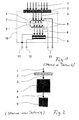
- FIG. 1 The arrangement shown shows a conventional use of a tunable Fabry-Perot interferometer 4 with an absorption analysis detector 9.
- the radiation to be analyzed 1 passes through a cut-off or broadband filter 2 in the detector housing 10.
- the filtered beam 3 strikes the tunable Fabry-Perot interferometer 4.
- the radiation is reflected several times, it comes to a multiple interference 7 within the gap.
- the center wavelength ⁇ m of the constructive interference can be changed by changing the gap distance 6, which is caused by applying a voltage 13 to the Fabry-Perot interferometer 4.
- an infrared detector 9 is arranged, which converts the narrow-band beam 8 into an electrical signal 12.
- the housing 10 and the other pole of the signal voltage 12 are connected to the ground terminal 11 connected.
- the cut-off wavelength or the bandwidth of the filter 2 are chosen so that the formation of harmonics in the multiple interference 7 is prevented.
- Cut-off filters or broadband filters 2, Fabry-Perot interferometer 4 and infrared detector 9 are arranged on a common optical main axis.
- Fig. 2 is the schematic representation after Fig. 1 further simplified and shown reduced to essential elements.
- Fig. 3 For example, the transmission spectrum of a broadband filter (BBF) 2 and the transmission peaks of a tunable Fabry-Perot interferometer 4 for different gap spacings 6 are shown.
- the reflectors of the Fabry-Perot interferometer 4 are designed as single-band reflectors for the spectral range 3 to 5 microns. In the spectral range 3 to 5 microns, the reflectors 5 show a very high reflection at the same time very low transmission. Outside this band with high reflection (stop band), there are areas and bands with high transmission both at shorter and longer wavelengths.
- stop band stop band
- the air gap of the Fabry-Perot filter has a distance of 2700 nm.
- the 1st and 2nd order interferences therefore arise at 4780 nm and 2850 nm, which corresponds to a free spectral range FSR of 1930 nm.
- the 1st order interference is observed at 4420 nm.
- the center wavelength of the 1st order interference is 4000 nm. If the gap distance is further reduced to 1600 nm, the interference 1 shifts. Order to a wavelength of 3375 nm. This is the tuning range of the reflectance range of the reflectors and the free spectral range of the Fabry-Perot interferometer 4 is almost exhausted.
- a broadband filter 2 prevents the higher order interferences, eg at a gap spacing of 2700 nm, from producing below 3000 nm.
- the broadband filter 2 also blocks radiation having a wavelength in excess of 5000 nm, which would otherwise pass the Fabry-Perot interferometer 4.
- Fig. 4 illustrated arrangement shows a first example of an inventive arrangement with tunable Fabry-Perot interferometer 4 and dichroic beam splitter 15 for absorption analysis in the spectral ranges of 3-5 microns and 8-12 microns.
- a bandpass filter 14 which is transparent at least in the spectral range of about 3-5 microns and 8-12 microns and blocks the range of about 5-8 microns, passes the emitted electromagnetic radiation from a source, not shown, after penetration of a medium in the a substance to be detected is or may be (also not shown) on a tunable Fabry-Perot interferometer 4, whose reflectors have stop bands in the spectral range of 3-5 microns and 8-12 microns.
- a dichroic beam splitter 15 is arranged at an angle of 45 °, on which the narrow-band beam 8 impinges.
- the dichroic beam splitter 15 may be designed as a short-pass or long-pass, so that either short-wave or long-wave radiation 16b passes through the beam splitter 15 in the direction of the incident radiation (main optical axis). Accordingly, the long-wave or short-wave radiation portion 16a is reflected. Since the angle of reflection is equal to the angle of incidence, the reflected radiation component forms 16a at an angle arranged at 45 ° beam splitter 15 at an angle of 90 ° to the transmitted radiation component 16b.
- the transmitted short-wave radiation component 16b when using a short pass as a beam splitter 15, reaches the infrared-optical detector 9b and the reflected long-wave radiation component 16a reaches the infrared-optical detector 9a.
- the transmitted long-wave radiation fraction 16b reaches the infrared-optical detector 9b and the reflected short-wave radiation fraction 16a reaches the infrared-optical detector 9a.
- Fabry-Perot interferometer 4 and the infrared optical detectors 9a and 9b can be connected to an electronic evaluation and control unit, for influencing the Fabry-Perot interferometer 4 and the evaluation, which also applies to the other embodiments can meet.
- Fig. 5 For example, the transmission peaks of a tunable Fabry-Perot interferometer 4 are shown for gap spacings of 5.0 ⁇ m, 4.25 ⁇ m, and 3.0 ⁇ m.
- the reflectors of the Fabry-Perot interferometer 4 have two stop bands and are designed for the spectral ranges 3.5-5 ⁇ m and 8-12 ⁇ m. Between 5 ⁇ m and 8 ⁇ m there is an area with high transmission (pass band). In the resting state of the Fabry-Perot interferometer 4, the air gap has a spacing of 5.0 microns. The 1st and 2nd order interferences therefore occur at 10.6 ⁇ m and 4.7 ⁇ m.
- the 1st and 2nd order interference are observed at 8.8 ⁇ m and 4.2 ⁇ m.
- the central wavelength of the 1st order interference is the central wavelength of the 1st order interference at 8.1 ⁇ m, and the 2nd order interference is formed at 3.9 ⁇ m.
- the transmittance of the long-pass beam splitter 15 is also shown.
- the beam splitter 15 Up to a wavelength of about 5 microns, the beam splitter 15 has a transmittance of nearly 0% and increases up to a wavelength of about 8 microns to about 100% and is transparent to about 12 microns. In this way, the beam splitter 15 reflects the short-wave interference that occurs at gap intervals of 5.0 microns, 4.25 microns and 3.8 microns at a wavelength of 4.7 microns, 4.2 microns and 3.9 microns on the infrared optical detector 9a (see Figure 4 ), while the long-wave interference reaches the infrared optical detector 9b. The beam splitting thus produces a clear relationship between the signal of the infrared-optical detectors 9a and 9b and the respective central wavelength of a transmission peak at a given gap distance 6.
- an inventive arrangement is based on the in Fig. 4 shown example.
- An infrared window 17, for example made of non-reflective silicon ensures that the radiation 1 in the two spectral ranges 3 - 5 microns and 8 - 12 microns is only slightly weakened and as more or less filtered radiation 18 in the Fabry-Perot interferometer 4 arrived.
- the beam splitter 19 is an unselective beam splitter made of a high-refractive dielectric material, eg silicon. This silicon beam splitter splits the narrow-band beam 8 into the beam bundles 20 almost wholly independently of the wavelength, approximately in a ratio of 1: 1, which impinge on the infrared-optical detectors 9a and 9b. Additional broadband filters 21 and 22 for the spectral ranges 3 - 5 ⁇ m and 8 - 12 ⁇ m in this case provide for the unambiguous assignment of the transmission peaks to the respective detectors 9a and 9b.
- a beam splitter 23 in the form of inclined at an angle wedge or pyramidal surfaces (micro-V trenches or microprisms) is used with a highly reflective gold coating, whereby a beam split to two or four beam 20 is achieved.
- Additional broadband filters 21 and 22 for the spectral ranges 3 - 5 microns and 8 - 12 microns provide in this case for the unambiguous assignment of the transmission peaks to respective infrared optical detectors 9a and 9b.
Abstract
Description
Die Erfindung betrifft eine Anordnung zur Bestimmung von Stoffen und/oder Stoffkonzentrationen, die in unterschiedlichsten Fluiden und insbesondere Gasen, die ein Gemisch einer Vielzahl von Stoffen enthalten können, die mit einem durchstimmbaren Fabry-Perot-Interferometer ausgebildet ist, das mit mikromechanischen Mitteln gefertigt werden kann. Unterschiedliche Stoffe können dabei zeitgleich in unterschiedlichen Spektralbereichen analysiert werden. Sie kann dabei für die Bestimmung von in Gemischen mit anderen Stoffen enthaltenen Gasen, wie z.B. Methan, Kohlendioxid, Kohlenmonoxid aber auch höher molekularer chemischer Verbindungen eingesetzt werden.The invention relates to an arrangement for the determination of substances and / or substance concentrations which can be contained in a wide variety of fluids and in particular gases, which may comprise a mixture of a multiplicity of substances, which is manufactured with a tunable Fabry-Perot interferometer, which are manufactured with micromechanical means can. Different substances can be analyzed simultaneously in different spectral ranges. It can be used for the determination of gases contained in mixtures with other substances, such as methane, carbon dioxide, carbon monoxide but also higher molecular chemical compounds.
Zur Analyse von Stoffen und Stoffkonzentrationen in Gemischen werden zunehmend infrarot-optische Verfahren eingesetzt. Die stoffspezifischen Absorptionsbanden hinterlassen bei polychromatischer Durchstrahlung der Probe vorwiegend im infraroten Wellenlängenbereich eine charakteristische spektrale Zusammensetzung der Strahlung. Neben aufwendigen und teuren Gitter-Spektrometern und Fourier-Transform-Spektrometern werden Photometer für spektrale Messungen im nahen bis fernen Infrarotbereich benutzt. Mittels spezieller schmalbandiger Bandpassfilter werden definierte Bereiche aus dem Gesamtspektrum herausgefiltert und für die Messung der stoffspezifischer Eigenschaften verwendet. Für einfache Messaufgaben, reichen häufig ein bzw. zwei spektrale Kanäle aus. Dafür werden Infrarot-Detektoren bereits durch den Hersteller mit Schmalbandfiltern ausgerüstet. In
Eine weitere bevorzugte Lösung stellt die Verwendung eines durchstimmbaren Filters auf der Basis eines Fabry-Perot-Filters (FP-Filter) dar. Zwei Reflektoren (Bragg-Reflektoren aus Stapeln hoch- und niedrigbrechender dielektrischer Schichtpaare) werden in geringem Abstand planparallel zueinander angeordnet und bilden im Zwischenraum einen optischen Resonator. Das Filter transmittiert nur Strahlung, deren Wellenlänge λm die (stark vereinfachte) Interferenzbedingung λm=2*n*d/m erfüllen, wobei n die Brechzahl des Mediums im Resonanzraum und m eine Ordnungszahl ist. Durch Variation des Abstandes der Reflektoren wird die Transmissionswellenlänge des Resonators verändert, so dass man eine Abstimmung des Filters über einen Wellenlängenbereich erreicht. Elektrostatische Antriebskräfte werden zur definierten Einstellung der Wellenlänge genutzt. Die Form der einzelnen Transmissionspeaks, auch Fringes genannt, ist sin2-förmig. Die Ordnungszahl m zeigt an, das die Transmissionspeaks periodisch auftreten. Der Abstand zwischen den benachbarten Transmissionspeaks wird Freier Spektralbereich FSR genannt und wird mit zunehmender Ordnungszahl immer kleiner. Meistens wünscht der Anwender von durchstimmbaren Filtern das Auftreten eines einzelnen Transmissionspeaks im Durchstimmbereich. Sind dies nur Transmissionspeaks einer gemeinsamen Ordnung, dann ist der Durchstimmbereich auf den Freien Spektralbereich FSR begrenzt. Die optische Mehrdeutigkeit wird in
In
In
Eine weitere Anordnung beruht auf der Verwendung von selektiv empfindlichen Detektorelementen, die im optischen Strahlengang nacheinander angeordnet sind. Das erste Detektorelement absorbiert die kurzwellige Strahlung im Spektralbereich 3 bis 5 µm vollständig und ist transparent für langwellige Strahlung im Spektralbereich 8 bis 12 µm, die das zweite Detektorelement absorbiert, das unmittelbar nach dem ersten Detektorelement angeordnet ist. Die Absorption von Strahlung im ersten und zweiten Detektorelement generiert jeweils elektrische Signale, die dem Spektralbereich 3 bis 5 µm und 8 bis 12 µm zugeordnet werden können und dann einer Auswertung zugeführt werden können.Another arrangement is based on the use of selectively sensitive detector elements which are arranged one after the other in the optical beam path. The first detector element completely absorbs the short-wave radiation in the
Der Erfindung liegt die Aufgabe zugrunde, Möglichkeiten zur Detektion von Stoffen und/oder Stoffkonzentrationen mit durchstimmbarem Fabry-Perot-Interferometer zu schaffen, das in einem oder mehreren breiten Spektralbändern durchgestimmt werden kann, ohne dass sich Mehrdeutigkeiten durch Interferenzen höherer Ordnung auf das Messergebnis auswirken.The invention has for its object to provide opportunities for the detection of substances and / or substance concentrations with tunable Fabry-Perot interferometer, which can be tuned in one or more wide spectral bands without ambiguities affect by higher-order interferences to the measurement result.
Erfindungsgemäß wird die Aufgabe mit einer Anordnung die die Merkmale des Anspruchs 1 aufweist, gelöst. Die Erfindung ausgestaltende und weiterbildende Merkmale sind in den untergeordneten Ansprüchen bezeichnet.According to the invention the object is achieved with an arrangement having the features of
Der Grundaufbau der erfindungsgemäßen Anordnung wird mit einem infrarotoptischen Eintrittsfenster, einem durchstimmbaren Fabry-Perot-Interferometer und einem Strahlteiler gebildet, die auf einer gemeinsamen optischen Hauptachse angeordnet sind und weist außerdem mindestens zwei infrarotoptische Detektoren auf. Auf die infrarotoptischen Detektoren sollten die Teilstrahlbündel nach einer Strahlteilung senkrecht auftreffen. Ein Gehäuse mit elektrischen Anschlüssen für das durchstimmbare Fabry-Perot-Interferometer und die infrarotoptischen Detektoren, in dem das infrarotoptische Eintrittsfenster montiert ist, schirmt Fabry-Perot-Interferometer, Strahlteiler und die Detektoren vor schädlichen Umwelteinflüssen ab.The basic structure of the arrangement according to the invention is formed with an infrared optical entrance window, a tunable Fabry-Perot interferometer and a beam splitter, which are arranged on a common optical main axis and also has at least two infrared-optical detectors. On the infrared-optical detectors, the sub-beam should impinge perpendicular to a beam splitting. A housing with electrical connections for the tunable Fabry-Perot interferometer and the infrared optical detectors, in which the infrared optical entrance window is mounted, shields Fabry-Perot interferometer, beam splitter and the detectors from harmful environmental influences.
Die von einer geeigneten Quelle emittierte elektromagnetische Strahlung durchdringt ein Medium, beispielsweise ein Gasgemisch oder eine Flüssigkeit, in der mindestens ein zu detektierender Stoff enthalten ist oder sein kann, bevor sie über das Infrarotfenster in das Gehäuse eintritt und darin mit den infrarotoptischen Detektoren wellenlängenselektiv unter Berücksichtigung des Absorptionsverhaltens des/der Stoffe(s) eine Detektion erfolgen kann.The electromagnetic radiation emitted by a suitable source penetrates a medium, for example a gas mixture or a liquid, in which at least one substance to be detected is or may be before it enters the housing via the infrared window and is wavelength-selective with the infrared-optical detectors in consideration the absorption behavior of the substance (s) can be detected.
Mit dem Fabry-Perot-Interferometer kann durch Beeinflussung des jeweiligen Spaltmasses zwischen seinen Reflektoren eine Auswahl eines Wellenlängenspektrums bzw. einer gezielten Wellenlänge vorgenommen werden, für die ein jeweiliger Stoff spezifisch ist.By influencing the respective gap dimension between its reflectors, the Fabry-Perot interferometer can be used to select a wavelength spectrum or a specific wavelength for which a respective substance is specific.
Um das Problem der Einflussnahme von ggf. auftretenden Interferenzen höherer Ordnungen zu vermeiden, kann mit der Aufteilung der aus dem Fabry-Perot-Interferometer austretenden elektromagnetischen Strahlung in mindestens zwei Teilstrahlbündel, die in verschiedene Richtungen emittiert werden, entgegengetreten werden, die dann auf jeweils einen infrarotoptischen Detektor auftreffen. Dabei erfolgt vor dem Auftreffen eine Filterung, so dass jeweils ein ganz spezifischer Wellenlängenbereich auf den jeweiligen infrarotoptischen Detektor auftreffen kann.In order to avoid the problem of influencing possibly occurring interferences of higher orders, the distribution of the electromagnetic radiation emerging from the Fabry-Perot interferometer can be counteracted in at least two partial beam beams which are emitted in different directions Infrared optical detector impinge. In this case, a filtering takes place before the impact, so that in each case a very specific wavelength range can impinge on the respective infrared-optical detector.
So kann eines der Teilstrahlbündel, dass von einem dichroitischen Strahlteiler in Richtung auf einen infrarotoptischen Detektor, der außerhalb der optischen Hauptachse angeordnet ist, reflektiert wird, bereits durch eine Bandpassfilterung durch den Strahlteiler einen begrenzten Wellenlängenbereich aufweisen, der sich vom Wellenlängenbereich, des Teilstrahlbündels für den der Strahlteiler transparent ist, unterscheidet. Letztgenanntes Teilstrahlbündel trifft in oder parallel zur optischen Hauptachse dann auf einen zweiten infrarotoptischen Detektor. Mit der so erreichbaren Wellenlängentrennung und Aufteilung auf die infrarotoptischen Detektoren kann der unerwünschte Effekt, der von ggf. auftretenden Interferenzen höherer Ordnungen, ggf. auch von anderen Stoffen, die nicht detektiert werden sollen, vermieden werden.Thus, one of the partial beams, which is reflected by a dichroic beam splitter in the direction of an infrared optical detector, which is arranged outside the main optical axis, already by bandpass filtering by the beam splitter have a limited wavelength range, which differs from the wavelength range of the sub-beam for the the beam splitter is transparent differs. Last mentioned partial beam in or parallel to the main optical axis then encounters a second infrared optical detector. With the thus achievable wavelength separation and distribution to the infrared optical detectors, the undesirable effect of possibly occurring higher-order interferences, possibly also of other substances that are not to be detected, can be avoided.
Wird ein Strahlteiler ohne eine solche Bandpassfilterwirkung eingesetzt, erfolgt die Teilung der Strahlung in Teilstrahlbündel, die ein gleiches Wellenlängenspektrum aufweisen. Die Teilstrahlbündel werden jedoch so vom Strahlteiler reflektiert, dass zumindest ein Teilstrahlbündel auf einen infrarotoptischen Detektor auftrifft, der nicht in der optischen Hauptachse angeordnet ist. Im Strahlengang der elektromagnetischen Strahlung vor jedem, zumindest jedoch vor einem der infrarotoptischen Detektoren kann dann ein Bandpassfilter angeordnet sein. Bei mehr als einem Bandpassfilter sind diese jeweils für unterschiedliche Wellenlängenbereiche transparent. So können ein Bandpassfilter im Wellenlängenbereich von 3 bis 5 µm und ein zweites Bandpassfilter im Wellenlängenbereich 8 bis 12 µm transparent sein.If a beam splitter without such a band-pass filter effect is used, the radiation is divided into sub-beam bundles which have the same wavelength spectrum. However, the sub-beams are reflected by the beam splitter so that at least one sub-beam impinges on an infrared-optical detector, which is not arranged in the main optical axis. In the beam path of the electromagnetic radiation in front of each, but at least before one of the infrared optical detectors, a bandpass filter can then be arranged. For more than one bandpass filter, these are transparent for different wavelength ranges. For example, a bandpass filter in the wavelength range of 3 to 5 μm and a second bandpass filter in the
Günstig ist es außerdem Bandpassfilter einzusetzen, die ein Stoppband des Fabry-Perot-Interferometers berücksichtigen, innerhalb dessen elektromagnetische Strahlung in einem Wellenlängenbereich von den Reflektoren des Fabry-Perot-Interferometers reflektiert werden kann. Der Wellenlängenbereich eines Stoppbandes kann vorteilhaft innerhalb eines Transmissionsbereichs der Bandpassfilter liegen.It is also advantageous to use bandpass filters which take into account a stop band of the Fabry-Perot interferometer, within which electromagnetic radiation in a wavelength range can be reflected by the reflectors of the Fabry-Perot interferometer. The wavelength range of a stopband may advantageously lie within a transmission range of the bandpass filter.
Bei der erfindungsgemäßen Anordnung besteht außerdem die Möglichkeit das Fabry-Perot-Interferometer und die infrarotoptischen Detektoren an eine elektronische Auswerte- und Steuereinheit anzuschließen. So kann am Fabry-Perot-Interferometer ein bestimmtes Spaltmaß eingestellt werden, um einen gewünschten Stoff detektieren zu können. Dabei kann dann, dass der elektronischen Auswerte- und Steuereinheit bekannte Spaltmaß, also auch die jeweilige Interferenzwellenlänge, bei der Auswertung der Messsignale der infrarotoptischen Detektoren berücksichtigt werden.In the arrangement according to the invention, there is also the possibility of the Fabry-Perot interferometer and to connect the infrared-optical detectors to an electronic evaluation and control unit. Thus, a certain gap can be set on the Fabry-Perot interferometer in order to be able to detect a desired substance. In this case, it is then possible to take into account the known gap dimension of the electronic evaluation and control unit, that is to say the respective interference wavelength, in the evaluation of the measurement signals of the infrared-optical detectors.
Für die Durchstimmung sollte das Spaltmaß im Bereich von 1 bis 10 µm verändert werden können.For tuning, the gap should be changed in the range of 1 to 10 microns.
Nachfolgend soll die Erfindung an Hand von Ausführungsbeispielen näher erläutert werden.The invention will be explained in more detail with reference to exemplary embodiments.
Dabei zeigen:
- Fig. 1
- eine schematische Darstellung eines herkömmlichen Infrarotdetektors mit durchstimmbarem Fabry-Perot-Filter (Stand der Technik);
- Fig. 2
- eine stark vereinfachte, schematische Darstellung eines herkömmlichen Infrarotdetektors mit durchstimmbarem Fabry-Perot-Filter (Stand der Technik);
- Fig. 3
- Transmissionsspektren eines Breitbandfilters und eines Fabry-Perot-Interferometers beim Durchstimmen;
- Fig. 4
- eine schematische Darstellung eines ersten Beispiels einer erfindungsgemäßen Anordnung mit durchstimmbarem Fabry-Perot-Interferometer und dichroitischem Strahlteiler;
- Fig. 5
- Transmissionsspektren eines Fabry-Perot-Interferometers mit dichroitischem Strahlteiler beim Durchstimmen sowie der Reflexion von Multibandreflektoren und des dichroitischen Strahlteilers;
- Fig. 6
- eine schematische Darstellung eines weiteren Beispiels mit durchstimmbarem Fabry-Perot-Interferometer und unselektivem Strahlteiler und
- Fig. 7
- eine schematische Darstellung eines zweiten Beispiels mit durchstimmbarem Fabry-Perot-Interferometer und Mikroprismen-Strahlteiler.
- Fig. 1
- a schematic representation of a conventional infrared detector with tunable Fabry-Perot filter (prior art);
- Fig. 2
- a highly simplified, schematic representation of a conventional infrared detector with tunable Fabry-Perot filter (prior art);
- Fig. 3
- Transmission spectra of a broadband filter and a Fabry-Perot interferometer while tuning;
- Fig. 4
- a schematic representation of a first example of an inventive arrangement with tunable Fabry-Perot interferometer and dichroic beam splitter;
- Fig. 5
- Transmission spectra of a Fabry-Perot interferometer with dichroic beamsplitter during tuning and reflection of multiband reflectors and the dichroic beamsplitter;
- Fig. 6
- a schematic representation of another example with tunable Fabry-Perot interferometer and unselective beam splitter and
- Fig. 7
- a schematic representation of a second example with tunable Fabry-Perot interferometer and microprism beam splitter.
Die in
In
In
Die in
In nicht dargestellter Form, können Fabry-Perot-Interferometer 4 und die infrarotoptischen Detektoren 9a und 9b an eine elektronische Auswerte- und Steuereinheit, für die Beeinflussung des Fabry-Perot-Interferometers 4 und die Auswertung angeschlossen werden, was auch auf die anderen Ausführungsbeispiele zu treffen kann.In a manner not shown, Fabry-
In
Die Abweichung von der stark vereinfachten Formel λm = 2*n*d/m zwischen den Wellenlängen der Interferenzen und dem Spaltmaß wird durch eine wellenlängenabhängige Änderung der Phase der reflektierten Strahlung bei der Vielfach-Interferenz verursacht.The deviation from the highly simplified formula λ m = 2 * n * d / m between the wavelengths of interference and the gap is caused by a wavelength-dependent change in the phase of the reflected radiation in the multiple interference.
In dem Diagramm ist ebenfalls der Transmissionsgrad des Langpass-Strahlteilers 15 eingezeichnet.In the diagram, the transmittance of the long-
Bis zu einer Wellenlänge von etwa 5 µm zeigt der Strahlteiler 15 einen Transmissionsgrad von nahezu 0% und steigt bis zu einer Wellenlänge von etwa 8 µm auf etwa 100% und ist bis etwa 12 µm transparent. Auf diese Weise reflektiert der Strahlteiler 15 die kurzwelligen Interferenzen, die bei Spaltabständen von 5,0 µm, 4,25 µm und 3,8 µm bei einer Wellenlänge von 4,7 µm, 4,2 µm und 3,9 µm auftreten auf den infrarotoptischen Detektor 9a (siehe
Das in
In
- 11
- IR-StrahlungIR radiation
- 22
- Cut-Off-Filter oder Breitband-FilterCut-off filter or broadband filter
- 33
- gefilterte IR-Strahlungfiltered IR radiation
- 44
- Fabry-Perot-InterferometerFabry-Perot interferometer
- 55
- Reflektorreflector
- 66
- veränderlicher Spaltabstand dvariable gap distance d
- 77
- VielstrahlinterferenzMultibeam interference
- 88th
- schmalbandiges Strahlungsbündelnarrowband radiation beam
- 99
- Infrarotoptischer DetektorInfrared optical detector
- 9a, b9a, b
- Infrarotoptischer DetektorInfrared optical detector
- 1010
- Gehäusecasing
- 1111
- Masse-AnschlussGround connection
- 1212
- Signal-AnschlussSignal connection
- 1313
- Spannungsanschlüsse für das Durchstimmen des Fabry-Perot-InterferometersVoltage connections for tuning the Fabry-Perot interferometer
- 1414
- BandpassfilterBandpass filter
- 1515
- dichroitischer Strahlteilerdichroic beam splitter
- 16a, b16a, b
- lang/kurzwelliges Teilstrahlenbündellong / short-wave partial beam
- 1717
- Infrarotfensterinfrared window
- 1818
- IR-Strahlung nach Passieren des InfrarotfenstersIR radiation after passing through the infrared window
- 1919
- Strahlteilerbeamsplitter
- 2020
- TeilstrahlenbündelPartial beams
- 2121
- BandpassfilterBandpass filter
- 2222
- BandpassfilterBandpass filter
- 2323
- Strahlteilerbeamsplitter
Claims (12)
elektromagnetische Strahlung durch ein Infrarotfenster (14, 17) in ein Gehäuse (10) auf ein durchstimmbares Fabry-Perot-Interferometer (4) gerichtet ist und
durch das Fabry-Perot-Interferometer (4) transmittierte elektromagnetische Strahlung mittels eines die Strahlung in mindestens zwei Teilstrahlbündel (16a, 16b, 20) zerlegenden Strahlteilers (15, 19, 23) richtet und dabei zumindest ein Teilstrahlbündel (16a, 16b, 20) auf einen außerhalb der optischen Hauptachse angeordneten infrarotoptischen Detektor (9a, 9b) durch Reflexion vom Strahlteiler (15, 19, 23) auftrifft.Arrangement for the determination of substances and / or substance concentrations using a tunable Fabry-Perot interferometer, in which
electromagnetic radiation is directed through an infrared window (14, 17) into a housing (10) on a tunable Fabry-Perot interferometer (4) and
electromagnetic radiation transmitted by the Fabry-Perot interferometer (4) is directed by means of a beam splitter (15, 19, 23) which splits the radiation into at least two partial beam bundles (16a, 16b, 20) and at least one partial beam bundle (16a, 16b, 20). to an outside of the main optical axis arranged infrared optical detector (9a, 9b) by reflection from the beam splitter (15, 19, 23) impinges.
Priority Applications (3)
| Application Number | Priority Date | Filing Date | Title |
|---|---|---|---|
| EP07090099A EP1995576B1 (en) | 2007-05-23 | 2007-05-23 | Assembly for detecting substances and/or substances concentrations with a fully adjustable Fabry-Perot interferometer |
| AT07090099T ATE506604T1 (en) | 2007-05-23 | 2007-05-23 | ARRANGEMENT FOR THE DETECTION OF SUBSTANCES AND/OR SUBSTANCE CONCENTRATIONS USING A TUNABLE FABRY-PEROT INTERFEROMETER |
| DE502007006991T DE502007006991D1 (en) | 2007-05-23 | 2007-05-23 | Arrangement for the detection of substances and / or substance concentrations with tunable Fabry-Perot interferometer |
Applications Claiming Priority (1)
| Application Number | Priority Date | Filing Date | Title |
|---|---|---|---|
| EP07090099A EP1995576B1 (en) | 2007-05-23 | 2007-05-23 | Assembly for detecting substances and/or substances concentrations with a fully adjustable Fabry-Perot interferometer |
Publications (2)
| Publication Number | Publication Date |
|---|---|
| EP1995576A1 true EP1995576A1 (en) | 2008-11-26 |
| EP1995576B1 EP1995576B1 (en) | 2011-04-20 |
Family
ID=38564574
Family Applications (1)
| Application Number | Title | Priority Date | Filing Date |
|---|---|---|---|
| EP07090099A Not-in-force EP1995576B1 (en) | 2007-05-23 | 2007-05-23 | Assembly for detecting substances and/or substances concentrations with a fully adjustable Fabry-Perot interferometer |
Country Status (3)
| Country | Link |
|---|---|
| EP (1) | EP1995576B1 (en) |
| AT (1) | ATE506604T1 (en) |
| DE (1) | DE502007006991D1 (en) |
Cited By (7)
| Publication number | Priority date | Publication date | Assignee | Title |
|---|---|---|---|---|
| CN102809564A (en) * | 2011-06-02 | 2012-12-05 | 江苏天瑞仪器股份有限公司 | System and method for distinguishing A-grade jade and B-grade jade |
| JP2013109055A (en) * | 2011-11-18 | 2013-06-06 | Seiko Epson Corp | Spectrometric measurement apparatus |
| CN103293158A (en) * | 2012-03-05 | 2013-09-11 | 江苏天瑞仪器股份有限公司 | Jade verification device and jade detector with same |
| EP2728323A1 (en) * | 2011-06-21 | 2014-05-07 | Olympus Corporation | Spectral image capturing device |
| JP2014190913A (en) * | 2013-03-28 | 2014-10-06 | Seiko Epson Corp | Light detector, printer, and image display unit |
| EP2821705A1 (en) | 2013-07-03 | 2015-01-07 | Karl Dungs GmbH & Co.KG | Method and device for determining the calorific value of a fuel gas mixture by means of an ionisation sensor |
| CN112666098A (en) * | 2020-11-06 | 2021-04-16 | 上海市第八人民医院 | Pathogenic pathogen detection system for intestinal infectious disease in summer |
Families Citing this family (1)
| Publication number | Priority date | Publication date | Assignee | Title |
|---|---|---|---|---|
| DE102014014872A1 (en) | 2014-10-06 | 2016-04-07 | Dräger Safety AG & Co. KGaA | System for transcutaneous determination of blood alcohol concentration |
Citations (2)
| Publication number | Priority date | Publication date | Assignee | Title |
|---|---|---|---|---|
| EP0536727A1 (en) * | 1991-10-09 | 1993-04-14 | ULTRAKUST electronic GmbH | Multispectral sensor |
| US5646729A (en) * | 1993-01-13 | 1997-07-08 | Vaisala Oy | Single-channel gas concentration measurement method and apparatus using a short-resonator Fabry-Perot interferometer |
-
2007
- 2007-05-23 DE DE502007006991T patent/DE502007006991D1/en active Active
- 2007-05-23 EP EP07090099A patent/EP1995576B1/en not_active Not-in-force
- 2007-05-23 AT AT07090099T patent/ATE506604T1/en active
Patent Citations (2)
| Publication number | Priority date | Publication date | Assignee | Title |
|---|---|---|---|---|
| EP0536727A1 (en) * | 1991-10-09 | 1993-04-14 | ULTRAKUST electronic GmbH | Multispectral sensor |
| US5646729A (en) * | 1993-01-13 | 1997-07-08 | Vaisala Oy | Single-channel gas concentration measurement method and apparatus using a short-resonator Fabry-Perot interferometer |
Non-Patent Citations (2)
| Title |
|---|
| N. NEUMANN: "Tunable infrared detector with integrated micromachined Fabry-Perot filter", PROCEEDINGS OF SPIE-MOEMS AND MINIATURIZED SYSTEMS, vol. IV, January 2007 (2007-01-01), pages 646606 - 1,646606-12 |
| NORBERT NEUMANN, MARTIN EBERMANN, KARLA HILLER, AND STEFFEN KURTH: "Tunable infrared detector with integrated micromachined Fabry-Perot filter", PROCEEDINGS OF SPIE -MOEMS AND MINIATURIZED SYSTEMS VI, vol. 6466, January 2007 (2007-01-01), pages 646606-1 - 646606-12, XP002455060 * |
Cited By (10)
| Publication number | Priority date | Publication date | Assignee | Title |
|---|---|---|---|---|
| CN102809564A (en) * | 2011-06-02 | 2012-12-05 | 江苏天瑞仪器股份有限公司 | System and method for distinguishing A-grade jade and B-grade jade |
| CN102809564B (en) * | 2011-06-02 | 2016-09-21 | 江苏天瑞仪器股份有限公司 | A kind of differentiate Aeschna melanictera A goods, the system of B goods and discrimination method thereof |
| EP2728323A1 (en) * | 2011-06-21 | 2014-05-07 | Olympus Corporation | Spectral image capturing device |
| EP2728323A4 (en) * | 2011-06-21 | 2015-03-18 | Olympus Corp | Spectral image capturing device |
| JP2013109055A (en) * | 2011-11-18 | 2013-06-06 | Seiko Epson Corp | Spectrometric measurement apparatus |
| CN103293158A (en) * | 2012-03-05 | 2013-09-11 | 江苏天瑞仪器股份有限公司 | Jade verification device and jade detector with same |
| JP2014190913A (en) * | 2013-03-28 | 2014-10-06 | Seiko Epson Corp | Light detector, printer, and image display unit |
| EP2821705A1 (en) | 2013-07-03 | 2015-01-07 | Karl Dungs GmbH & Co.KG | Method and device for determining the calorific value of a fuel gas mixture by means of an ionisation sensor |
| DE102013106987A1 (en) | 2013-07-03 | 2015-01-08 | Karl Dungs Gmbh & Co. Kg | Method and device for determining a calorific value and gas-powered device with such a device |
| CN112666098A (en) * | 2020-11-06 | 2021-04-16 | 上海市第八人民医院 | Pathogenic pathogen detection system for intestinal infectious disease in summer |
Also Published As
| Publication number | Publication date |
|---|---|
| DE502007006991D1 (en) | 2011-06-01 |
| EP1995576B1 (en) | 2011-04-20 |
| ATE506604T1 (en) | 2011-05-15 |
Similar Documents
| Publication | Publication Date | Title |
|---|---|---|
| EP1995576B1 (en) | Assembly for detecting substances and/or substances concentrations with a fully adjustable Fabry-Perot interferometer | |
| DE19754910C2 (en) | Wavelength detection on fiber Bragg grating sensors | |
| EP3204738B1 (en) | Optical filter element for devices for converting spectral information into location information | |
| EP0494883B1 (en) | Process and device for fabry-perot spectroscopy | |
| DE60103482T2 (en) | light interference | |
| WO1997033147A2 (en) | Analytic process using porous silicon to detect a substance or determine the concentration of a substance in solutions as well as an analytic device for such a process | |
| EP3465165B1 (en) | Method and device for raman spectroscopy | |
| DE102006034731A1 (en) | Tunable dual-band Fabry-Perot filter | |
| DE102018208684B4 (en) | MONOLITHICALLY DESIGNED SPECTRAL APPARATUS | |
| EP1523663A1 (en) | Device and method for optical spectroscopy, optical sensor and use of said device | |
| DE102014014981A1 (en) | Device for the spectrometric detection of light pulses | |
| DE3825683C1 (en) | ||
| DE69627419T2 (en) | Fourier spectrometer with dichroic Michelson mirrors for two wavelength bands | |
| DE19845701A1 (en) | Arrangements to monitor the performance of DWDM multi-wavelength systems | |
| DE3528294A1 (en) | Method for the fibre-optical, spectrally coded transmission of the value of a variable physical measured quantity | |
| DE102016108544A1 (en) | Measuring device and method for detecting different gases and gas concentrations | |
| JP7195189B2 (en) | Spectrometer | |
| CN110926613B (en) | Coma-eliminating broadband high-resolution spectrometer | |
| EP2028463B1 (en) | Assembly and method for wavelength referencing of variable frequency Fabry-Perot interferometers | |
| WO2020083875A1 (en) | Interferometer element, spectrometer and method for operating an interferometer | |
| DE102018217731A1 (en) | LiDAR device | |
| DE102014108138B4 (en) | Spectral sensor for the spectral analysis of incident light | |
| DE19744565C2 (en) | Wavelength measuring device for short laser pulses | |
| DE102019212986A1 (en) | Fabry-Pérot interferometer and related manufacturing process | |
| EP3779408A1 (en) | Measuring device and method for detecting material concentration |
Legal Events
| Date | Code | Title | Description |
|---|---|---|---|
| PUAI | Public reference made under article 153(3) epc to a published international application that has entered the european phase |
Free format text: ORIGINAL CODE: 0009012 |
|
| 17P | Request for examination filed |
Effective date: 20080513 |
|
| AK | Designated contracting states |
Kind code of ref document: A1 Designated state(s): AT BE BG CH CY CZ DE DK EE ES FI FR GB GR HU IE IS IT LI LT LU LV MC MT NL PL PT RO SE SI SK TR |
|
| AX | Request for extension of the european patent |
Extension state: AL BA HR MK RS |
|
| AKX | Designation fees paid |
Designated state(s): AT BE BG CH CY CZ DE DK EE ES FI FR GB GR HU IE IS IT LI LT LU LV MC MT NL PL PT RO SE SI SK TR |
|
| GRAP | Despatch of communication of intention to grant a patent |
Free format text: ORIGINAL CODE: EPIDOSNIGR1 |
|
| GRAC | Information related to communication of intention to grant a patent modified |
Free format text: ORIGINAL CODE: EPIDOSCIGR1 |
|
| RIN1 | Information on inventor provided before grant (corrected) |
Inventor name: EBERMAN, MARTIN, DIPL.-ING. Inventor name: HEINZE, MATTHIAS, DR.-ING. Inventor name: NEUMANN, NORBERT, DR. ING. |
|
| GRAS | Grant fee paid |
Free format text: ORIGINAL CODE: EPIDOSNIGR3 |
|
| GRAA | (expected) grant |
Free format text: ORIGINAL CODE: 0009210 |
|
| AK | Designated contracting states |
Kind code of ref document: B1 Designated state(s): AT BE BG CH CY CZ DE DK EE ES FI FR GB GR HU IE IS IT LI LT LU LV MC MT NL PL PT RO SE SI SK TR |
|
| REG | Reference to a national code |
Ref country code: GB Ref legal event code: FG4D Free format text: NOT ENGLISH |
|
| REG | Reference to a national code |
Ref country code: CH Ref legal event code: EP |
|
| REG | Reference to a national code |
Ref country code: IE Ref legal event code: FG4D Free format text: LANGUAGE OF EP DOCUMENT: GERMAN |
|
| REF | Corresponds to: |
Ref document number: 502007006991 Country of ref document: DE Date of ref document: 20110601 Kind code of ref document: P |
|
| REG | Reference to a national code |
Ref country code: DE Ref legal event code: R096 Ref document number: 502007006991 Country of ref document: DE Effective date: 20110601 |
|
| REG | Reference to a national code |
Ref country code: SE Ref legal event code: TRGR |
|
| REG | Reference to a national code |
Ref country code: NL Ref legal event code: VDEP Effective date: 20110420 |
|
| LTIE | Lt: invalidation of european patent or patent extension |
Effective date: 20110420 |
|
| PG25 | Lapsed in a contracting state [announced via postgrant information from national office to epo] |
Ref country code: PT Free format text: LAPSE BECAUSE OF FAILURE TO SUBMIT A TRANSLATION OF THE DESCRIPTION OR TO PAY THE FEE WITHIN THE PRESCRIBED TIME-LIMIT Effective date: 20110822 Ref country code: LT Free format text: LAPSE BECAUSE OF FAILURE TO SUBMIT A TRANSLATION OF THE DESCRIPTION OR TO PAY THE FEE WITHIN THE PRESCRIBED TIME-LIMIT Effective date: 20110420 |
|
| REG | Reference to a national code |
Ref country code: IE Ref legal event code: FD4D |
|
| BERE | Be: lapsed |
Owner name: INFRATEC G.M.B.H. Effective date: 20110531 |
|
| PG25 | Lapsed in a contracting state [announced via postgrant information from national office to epo] |
Ref country code: SI Free format text: LAPSE BECAUSE OF FAILURE TO SUBMIT A TRANSLATION OF THE DESCRIPTION OR TO PAY THE FEE WITHIN THE PRESCRIBED TIME-LIMIT Effective date: 20110420 Ref country code: IS Free format text: LAPSE BECAUSE OF FAILURE TO SUBMIT A TRANSLATION OF THE DESCRIPTION OR TO PAY THE FEE WITHIN THE PRESCRIBED TIME-LIMIT Effective date: 20110820 Ref country code: LV Free format text: LAPSE BECAUSE OF FAILURE TO SUBMIT A TRANSLATION OF THE DESCRIPTION OR TO PAY THE FEE WITHIN THE PRESCRIBED TIME-LIMIT Effective date: 20110420 Ref country code: CY Free format text: LAPSE BECAUSE OF FAILURE TO SUBMIT A TRANSLATION OF THE DESCRIPTION OR TO PAY THE FEE WITHIN THE PRESCRIBED TIME-LIMIT Effective date: 20110420 Ref country code: GR Free format text: LAPSE BECAUSE OF FAILURE TO SUBMIT A TRANSLATION OF THE DESCRIPTION OR TO PAY THE FEE WITHIN THE PRESCRIBED TIME-LIMIT Effective date: 20110721 Ref country code: ES Free format text: LAPSE BECAUSE OF FAILURE TO SUBMIT A TRANSLATION OF THE DESCRIPTION OR TO PAY THE FEE WITHIN THE PRESCRIBED TIME-LIMIT Effective date: 20110731 |
|
| PG25 | Lapsed in a contracting state [announced via postgrant information from national office to epo] |
Ref country code: MC Free format text: LAPSE BECAUSE OF NON-PAYMENT OF DUE FEES Effective date: 20110531 Ref country code: NL Free format text: LAPSE BECAUSE OF FAILURE TO SUBMIT A TRANSLATION OF THE DESCRIPTION OR TO PAY THE FEE WITHIN THE PRESCRIBED TIME-LIMIT Effective date: 20110420 Ref country code: MT Free format text: LAPSE BECAUSE OF FAILURE TO SUBMIT A TRANSLATION OF THE DESCRIPTION OR TO PAY THE FEE WITHIN THE PRESCRIBED TIME-LIMIT Effective date: 20110420 |
|
| REG | Reference to a national code |
Ref country code: CH Ref legal event code: PL |
|
| PG25 | Lapsed in a contracting state [announced via postgrant information from national office to epo] |
Ref country code: IE Free format text: LAPSE BECAUSE OF FAILURE TO SUBMIT A TRANSLATION OF THE DESCRIPTION OR TO PAY THE FEE WITHIN THE PRESCRIBED TIME-LIMIT Effective date: 20110420 Ref country code: EE Free format text: LAPSE BECAUSE OF FAILURE TO SUBMIT A TRANSLATION OF THE DESCRIPTION OR TO PAY THE FEE WITHIN THE PRESCRIBED TIME-LIMIT Effective date: 20110420 Ref country code: CH Free format text: LAPSE BECAUSE OF NON-PAYMENT OF DUE FEES Effective date: 20110531 Ref country code: CZ Free format text: LAPSE BECAUSE OF FAILURE TO SUBMIT A TRANSLATION OF THE DESCRIPTION OR TO PAY THE FEE WITHIN THE PRESCRIBED TIME-LIMIT Effective date: 20110420 Ref country code: LI Free format text: LAPSE BECAUSE OF NON-PAYMENT OF DUE FEES Effective date: 20110531 |
|
| PLBE | No opposition filed within time limit |
Free format text: ORIGINAL CODE: 0009261 |
|
| STAA | Information on the status of an ep patent application or granted ep patent |
Free format text: STATUS: NO OPPOSITION FILED WITHIN TIME LIMIT |
|
| PG25 | Lapsed in a contracting state [announced via postgrant information from national office to epo] |
Ref country code: DK Free format text: LAPSE BECAUSE OF FAILURE TO SUBMIT A TRANSLATION OF THE DESCRIPTION OR TO PAY THE FEE WITHIN THE PRESCRIBED TIME-LIMIT Effective date: 20110420 Ref country code: PL Free format text: LAPSE BECAUSE OF FAILURE TO SUBMIT A TRANSLATION OF THE DESCRIPTION OR TO PAY THE FEE WITHIN THE PRESCRIBED TIME-LIMIT Effective date: 20110420 Ref country code: RO Free format text: LAPSE BECAUSE OF FAILURE TO SUBMIT A TRANSLATION OF THE DESCRIPTION OR TO PAY THE FEE WITHIN THE PRESCRIBED TIME-LIMIT Effective date: 20110420 Ref country code: SK Free format text: LAPSE BECAUSE OF FAILURE TO SUBMIT A TRANSLATION OF THE DESCRIPTION OR TO PAY THE FEE WITHIN THE PRESCRIBED TIME-LIMIT Effective date: 20110420 |
|
| REG | Reference to a national code |
Ref country code: FR Ref legal event code: ST Effective date: 20120217 |
|
| 26N | No opposition filed |
Effective date: 20120123 |
|
| PG25 | Lapsed in a contracting state [announced via postgrant information from national office to epo] |
Ref country code: BE Free format text: LAPSE BECAUSE OF NON-PAYMENT OF DUE FEES Effective date: 20110531 |
|
| PG25 | Lapsed in a contracting state [announced via postgrant information from national office to epo] |
Ref country code: FR Free format text: LAPSE BECAUSE OF NON-PAYMENT OF DUE FEES Effective date: 20110620 |
|
| REG | Reference to a national code |
Ref country code: DE Ref legal event code: R097 Ref document number: 502007006991 Country of ref document: DE Effective date: 20120123 |
|
| PG25 | Lapsed in a contracting state [announced via postgrant information from national office to epo] |
Ref country code: IT Free format text: LAPSE BECAUSE OF FAILURE TO SUBMIT A TRANSLATION OF THE DESCRIPTION OR TO PAY THE FEE WITHIN THE PRESCRIBED TIME-LIMIT Effective date: 20110420 |
|
| PG25 | Lapsed in a contracting state [announced via postgrant information from national office to epo] |
Ref country code: LU Free format text: LAPSE BECAUSE OF NON-PAYMENT OF DUE FEES Effective date: 20110523 |
|
| PG25 | Lapsed in a contracting state [announced via postgrant information from national office to epo] |
Ref country code: BG Free format text: LAPSE BECAUSE OF FAILURE TO SUBMIT A TRANSLATION OF THE DESCRIPTION OR TO PAY THE FEE WITHIN THE PRESCRIBED TIME-LIMIT Effective date: 20110720 |
|
| REG | Reference to a national code |
Ref country code: AT Ref legal event code: MM01 Ref document number: 506604 Country of ref document: AT Kind code of ref document: T Effective date: 20120523 |
|
| PG25 | Lapsed in a contracting state [announced via postgrant information from national office to epo] |
Ref country code: AT Free format text: LAPSE BECAUSE OF NON-PAYMENT OF DUE FEES Effective date: 20120523 |
|
| PG25 | Lapsed in a contracting state [announced via postgrant information from national office to epo] |
Ref country code: TR Free format text: LAPSE BECAUSE OF FAILURE TO SUBMIT A TRANSLATION OF THE DESCRIPTION OR TO PAY THE FEE WITHIN THE PRESCRIBED TIME-LIMIT Effective date: 20110420 |
|
| PG25 | Lapsed in a contracting state [announced via postgrant information from national office to epo] |
Ref country code: HU Free format text: LAPSE BECAUSE OF FAILURE TO SUBMIT A TRANSLATION OF THE DESCRIPTION OR TO PAY THE FEE WITHIN THE PRESCRIBED TIME-LIMIT Effective date: 20110420 |
|
| PGFP | Annual fee paid to national office [announced via postgrant information from national office to epo] |
Ref country code: DE Payment date: 20200519 Year of fee payment: 14 Ref country code: FI Payment date: 20200522 Year of fee payment: 14 |
|
| PGFP | Annual fee paid to national office [announced via postgrant information from national office to epo] |
Ref country code: GB Payment date: 20200527 Year of fee payment: 14 Ref country code: SE Payment date: 20200527 Year of fee payment: 14 |
|
| REG | Reference to a national code |
Ref country code: DE Ref legal event code: R119 Ref document number: 502007006991 Country of ref document: DE |
|
| REG | Reference to a national code |
Ref country code: FI Ref legal event code: MAE |
|
| REG | Reference to a national code |
Ref country code: SE Ref legal event code: EUG |
|
| GBPC | Gb: european patent ceased through non-payment of renewal fee |
Effective date: 20210523 |
|
| PG25 | Lapsed in a contracting state [announced via postgrant information from national office to epo] |
Ref country code: FI Free format text: LAPSE BECAUSE OF NON-PAYMENT OF DUE FEES Effective date: 20210523 Ref country code: SE Free format text: LAPSE BECAUSE OF NON-PAYMENT OF DUE FEES Effective date: 20210524 |
|
| PG25 | Lapsed in a contracting state [announced via postgrant information from national office to epo] |
Ref country code: GB Free format text: LAPSE BECAUSE OF NON-PAYMENT OF DUE FEES Effective date: 20210523 Ref country code: DE Free format text: LAPSE BECAUSE OF NON-PAYMENT OF DUE FEES Effective date: 20211201 |