EP1995371A1 - Electric household appliance - Google Patents
Electric household appliance Download PDFInfo
- Publication number
- EP1995371A1 EP1995371A1 EP07108567A EP07108567A EP1995371A1 EP 1995371 A1 EP1995371 A1 EP 1995371A1 EP 07108567 A EP07108567 A EP 07108567A EP 07108567 A EP07108567 A EP 07108567A EP 1995371 A1 EP1995371 A1 EP 1995371A1
- Authority
- EP
- European Patent Office
- Prior art keywords
- drum
- air
- steam
- household appliance
- manifold portion
- Prior art date
- Legal status (The legal status is an assumption and is not a legal conclusion. Google has not performed a legal analysis and makes no representation as to the accuracy of the status listed.)
- Granted
Links
Images


Classifications
-
- D—TEXTILES; PAPER
- D06—TREATMENT OF TEXTILES OR THE LIKE; LAUNDERING; FLEXIBLE MATERIALS NOT OTHERWISE PROVIDED FOR
- D06F—LAUNDERING, DRYING, IRONING, PRESSING OR FOLDING TEXTILE ARTICLES
- D06F58/00—Domestic laundry dryers
- D06F58/30—Drying processes
-
- D—TEXTILES; PAPER
- D06—TREATMENT OF TEXTILES OR THE LIKE; LAUNDERING; FLEXIBLE MATERIALS NOT OTHERWISE PROVIDED FOR
- D06F—LAUNDERING, DRYING, IRONING, PRESSING OR FOLDING TEXTILE ARTICLES
- D06F2101/00—User input for the control of domestic laundry washing machines, washer-dryers or laundry dryers
-
- D—TEXTILES; PAPER
- D06—TREATMENT OF TEXTILES OR THE LIKE; LAUNDERING; FLEXIBLE MATERIALS NOT OTHERWISE PROVIDED FOR
- D06F—LAUNDERING, DRYING, IRONING, PRESSING OR FOLDING TEXTILE ARTICLES
- D06F2103/00—Parameters monitored or detected for the control of domestic laundry washing machines, washer-dryers or laundry dryers
- D06F2103/40—Opening or locking status of doors
-
- D—TEXTILES; PAPER
- D06—TREATMENT OF TEXTILES OR THE LIKE; LAUNDERING; FLEXIBLE MATERIALS NOT OTHERWISE PROVIDED FOR
- D06F—LAUNDERING, DRYING, IRONING, PRESSING OR FOLDING TEXTILE ARTICLES
- D06F2105/00—Systems or parameters controlled or affected by the control systems of washing machines, washer-dryers or laundry dryers
- D06F2105/28—Electric heating
-
- D—TEXTILES; PAPER
- D06—TREATMENT OF TEXTILES OR THE LIKE; LAUNDERING; FLEXIBLE MATERIALS NOT OTHERWISE PROVIDED FOR
- D06F—LAUNDERING, DRYING, IRONING, PRESSING OR FOLDING TEXTILE ARTICLES
- D06F2105/00—Systems or parameters controlled or affected by the control systems of washing machines, washer-dryers or laundry dryers
- D06F2105/38—Conditioning or finishing, e.g. control of perfume injection
- D06F2105/40—Conditioning or finishing, e.g. control of perfume injection using water or steam
-
- D—TEXTILES; PAPER
- D06—TREATMENT OF TEXTILES OR THE LIKE; LAUNDERING; FLEXIBLE MATERIALS NOT OTHERWISE PROVIDED FOR
- D06F—LAUNDERING, DRYING, IRONING, PRESSING OR FOLDING TEXTILE ARTICLES
- D06F2105/00—Systems or parameters controlled or affected by the control systems of washing machines, washer-dryers or laundry dryers
- D06F2105/62—Stopping or disabling machine operation
-
- D—TEXTILES; PAPER
- D06—TREATMENT OF TEXTILES OR THE LIKE; LAUNDERING; FLEXIBLE MATERIALS NOT OTHERWISE PROVIDED FOR
- D06F—LAUNDERING, DRYING, IRONING, PRESSING OR FOLDING TEXTILE ARTICLES
- D06F34/00—Details of control systems for washing machines, washer-dryers or laundry dryers
- D06F34/14—Arrangements for detecting or measuring specific parameters
- D06F34/20—Parameters relating to constructional components, e.g. door sensors
-
- D—TEXTILES; PAPER
- D06—TREATMENT OF TEXTILES OR THE LIKE; LAUNDERING; FLEXIBLE MATERIALS NOT OTHERWISE PROVIDED FOR
- D06F—LAUNDERING, DRYING, IRONING, PRESSING OR FOLDING TEXTILE ARTICLES
- D06F58/00—Domestic laundry dryers
- D06F58/02—Domestic laundry dryers having dryer drums rotating about a horizontal axis
-
- D—TEXTILES; PAPER
- D06—TREATMENT OF TEXTILES OR THE LIKE; LAUNDERING; FLEXIBLE MATERIALS NOT OTHERWISE PROVIDED FOR
- D06F—LAUNDERING, DRYING, IRONING, PRESSING OR FOLDING TEXTILE ARTICLES
- D06F58/00—Domestic laundry dryers
- D06F58/20—General details of domestic laundry dryers
- D06F58/203—Laundry conditioning arrangements
Definitions
- the present invention relates to an electric household appliance.
- the present invention relates to an electric household appliance corresponding to a rotary-drum home washing machine or laundry drier, to which the following description refers purely by way of example.
- rotary-drum laundry driers substantially comprise a substantially parallelepiped-shaped casing; a cylindrical laundry drying tub or chamber fixed horizontally inside the casing, directly facing a laundry loading/unloading opening formed in the front face of the casing; a door hinged to the front face of the casing to rotate to and from a work position closing the opening in the front face and sealing the drying tub; a cylindrical, perforated-wall laundry drum housed in axially rotating manner inside the wash/drying tub; and an electric motor for rotating the laundry drum about its longitudinal axis inside the drying tub.
- Rotary-drum driers of the above type also comprise a hot-air generator for circulating inside the drying tub hot, dry air, which flows through the laundry drum and over the laundry inside to dry the laundry rapidly.
- Vented driers feature an open-circuit, hot-air generator, which comprises an intake manifold connecting the rear wall of the drying tub to an air inlet; and an air exhaust manifold connected at one end to the front wall of the drying tub, and at the other end to an air exhaust outlet at the front of the casing.
- the open-circuit, hot-air generator also comprises an electric heating element located along the intake manifold to heat the air before it is fed into the drying tub; and a ventilation device located along the exhaust manifold to draw air along the intake manifold, feed the hot air through the drying tub, and expel the moist air through the exhaust manifold.
- the ventilation device is defined by a fan located along the exhaust manifold; and by a drive interposed between the drum electric motor and the fan to rotate the fan.
- an electric household appliance as claimed in Claim 1 and preferably, though not necessarily, in any one of the Claims depending directly or indirectly on Claim 1.
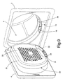
- number 1 indicates as a whole an electric household appliance, in particular a home laundry drier, substantially comprising a preferably, though not necessarily, parallelepiped-shaped casing 2; a drum 3 for housing the laundry to be dried, and which is housed in axially rotating manner and preferably, though not necessarily, horizontally inside casing 2, directly facing a laundry loading/unloading opening 2a formed in the front face of casing 2; a door 4 hinged to the front face of casing 2 to rotate to and from a work position closing opening 2a in the front face and sealing drum 3; and an open-circuit, hot-air generator 5 housed inside casing 2 to circulate hot, dry air inside drum 3 and over the laundry inside the drum to dry the laundry rapidly.
- a home laundry drier substantially comprising a preferably, though not necessarily, parallelepiped-shaped casing 2; a drum 3 for housing the laundry to be dried, and which is housed in axially rotating manner and preferably, though not necessarily, horizontally inside casing 2, directly facing a laundry
- Drier 1 also comprises an electric motor 7 or similar for rotating drum 3 about its longitudinal axis L, preferably, though not necessarily, inside a drying tub 6 housed inside casing 2.
- longitudinal axis L coincides with the longitudinal axis of drying tub 6.
- hot-air generator 5 provides for gradually drawing in air from outside drum 3; heating the drawn-in air to a predetermined temperature; and drawing the damp air out of drum 3.
- hot-air generator 5 provides for continually drawing in outside air, heating and feeding it into drum 3 to rapidly dry the laundry inside the drum, and exhausting the damp air from drum 3.
- Hot-air generator 5 substantially comprises: an air intake manifold 8 having a first end connected to the rear wall of drum 3, and a second end connected to an air inlet 9 formed preferably, though not necessarily, in casing 2; an electric heating element 10 (in the example shown, a resistor) located along intake manifold 8 to rapidly heat the airflow through inlet 9; an exhaust manifold 11 having a first end connected preferably, though not necessarily, to the front wall of drum 3, and a second end connected to an exhaust outlet 12 preferably, though not necessarily, in the front face of casing 2; and a centrifugal fan 13 located along exhaust manifold 11 to produce, inside intake manifold 8 and exhaust manifold 11, an airflow, which flows through drum 3 and over the laundry inside the drum, and is exhausted to the outside.
- an electric heating element 10 in the example shown, a resistor
- Centrifugal fan 13 is connected by a drive mechanism (shown by the dash line) to electric motor 7, which rotates both fan 13 and drum 3 about respective axes of rotation as a function of control signals Sp generated by a control unit 14 during a user-selected drying cycle.
- Drier 1 also comprises a steam generator 15, which, as a function of control signals Sp generated by control unit 14, feeds a steam jet into drum 3 to eliminate or at any rate greatly reduce creasing of the fabrics during the drying cycle.
- a steam generator 15 which, as a function of control signals Sp generated by control unit 14, feeds a steam jet into drum 3 to eliminate or at any rate greatly reduce creasing of the fabrics during the drying cycle.
- exhaust manifold 11 comprises a first manifold portion 16 extending inside casing 2; and a second manifold portion 17 fixed stably to door 4 and designed to connect to first portion 16, when door 4 closes opening 2a, to connect first portion 16 to drum 3.
- first manifold portion 16 preferably, though not necessarily, extends inside the front wall of casing 2, and has one end, i.e. its outlet, connected to exhaust outlet 12, and the opposite end, i.e. its inlet, connected to an opening 18 formed in an annular portion 35 of casing 2 defining the peripheral edge of opening 2a of drier 1 for housing door 4.
- centrifugal fan 13 is located along first manifold portion 16, downstream from second portion 17 along the air/steam flow path from drum 3 to exhaust outlet 12.
- Second portion 17 of exhaust manifold 11 is defined by a substantially cylindrical box member or shell 21, which projects from the inner face of door 4, extends through opening 2a, and projects partly inside drum 3.
- shell 21 comprises a front wall 22 positioned facing drum 3 when door 4 closes opening 2a, and in turn comprising a perforated central portion 22a through which the air/steam in drum 3 flows to the inlet of exhaust manifold 11.
- the lateral wall 23 of shell 21 has a slit 24 which, when door 4 closes opening 2a, is positioned facing opening 18 to connect second manifold portion 17 to the inlet of first manifold portion 16, and so allow the air/steam flowing along second portion 17 to flow freely into first portion 16 and out to the outside.
- hot-air generators Unlike known open-circuit, hot-air generators, open-circuit, hot-air generator 5 of drier 1 comprises shutter means 30 for selectively opening/closing exhaust manifold 11 ( Figures 2 , 3 ) to allow/prevent free outflow of the air/steam from drum 3.
- shutter means 30 selectively close exhaust manifold 11 at the crease-removing stage to prevent the steam inside drum 3 from flowing freely along exhaust manifold 11 to the outside ( Figure 3 ).
- shutter means 30 comprise a shutter plate 25 mounted on the inner surface 22b of front wall 22 to move between an open position (shown schematically in Figure 2 ) - in which the air/steam in drum 3 flows freely through perforated portion 22a of front wall 22 into exhaust manifold 11 - and a closed position (shown schematically in Figure 3 ) - in which the holes in central perforated portion 22a are closed completely to prevent the air/steam in drum 3 from flowing freely to the outside along exhaust manifold 11.
- shutter plate 25 is fitted movably to inner surface 22b of front wall 22, and is defined by a plate having a number of central holes which, when shutter plate 25 is in the open position, are aligned with the holes in perforated portion 22a of front wall 22.
- shutter plate 25 is mounted to slide along two lateral rails 26 on the inner surface of front wall 22, and has a central operating tab 36 projecting towards drum 3 through a slot formed through front wall 22, to allow the user to move shutter plate 25 manually between the open and closed position.
- shutter means 30 comprise a flap 32 fitted, at opening 18, to annular portion 35 of casing 2 defining the inner peripheral edge of opening 2a of drier 1, and which slides between an open position (shown schematically in Figures 6 , 7 ) allowing free air/steam flow from drum 3 to exhaust manifold 11, and a closed position (shown schematically in Figure 8 ) closing opening 18 to prevent air/steam flow from drum 3 to exhaust manifold 11.
- flap 32 seals opening 18 to prevent free air/steam flow from second portion 17 to first portion 16; whereas, in the open position, flap 32 is shifted to the side of opening 18 to fully open and connect opening 18 to slit 24 in shell 21, and so allow free air/steam flow from second portion 17 to first portion 16 of the exhaust manifold.
- shutter means 30 comprise a flap 33 fitted, at slit 24, to lateral wall 23 of shell 21, and which slides between an open position opening slit 24 and allowing free air/steam flow from drum 3 to exhaust manifold 11, and a closed position closing slit 24 to prevent air/steam flow from drum 3 to first portion 16 of exhaust manifold 11.
- flap 33 seals slit 24; whereas, in the open position, flap 33 is positioned, on lateral wall 23 of shell 21, to the side of slit 24 to fully open and connect slit 24 to opening 18 in annular portion 35 of casing 2.
- hot-air generator 5 may comprise a sensor 31 ( Figures 2 , 3 , 7, 8 ) for determining the open/closed position of shutter means 30, and which, on detecting a closed position of shutter means 30, prevents control unit 14 from activating a drying cycle, and conversely, on detecting an open position of shutter means 30, prevents control unit 14 from activating a crease-removing cycle.
- sensor 31 may conveniently comprise a microswitch, which switches from one on/off state to the other when shutter means 30 are set to the open or closed position.
- sensor 31 is located on wall 22 of shell 21, and is switched by shutter plate 25 moving into a given open/closed position.
- sensor 31 is located on annular portion 35, and is switched by flap 32 moving into a given open/closed position; and, in the Figure 9 example, sensor 31 is located on lateral wall 23 of shell 21, and is switched by flap 33 moving into a given open/closed position. Sensor 31 may obviously also be located directly on flap 33 or in any other position in which it is switched by a change in position of flap 33.
- control unit 14 determines whether or not shutter means 30 are in the open position, and, if they are not, disables the user-set drying cycle.
- control unit 14 activates hot-air generator 5 and, simultaneously, electric motor 7, which rotates drum 3 and centrifugal fan 13, which expels the damp air along the, in this case, fully open exhaust manifold 11.
- the user sets shutter means 30 to the closed position closing exhaust manifold 11, and activates a crease-removing cycle using selector means (not shown).
- control unit 14 determines whether or not shutter means 30 are in the closed position, and, if they are not, disables the user-set crease-removing cycle.
- control unit 14 activates steam generator 15 and, simultaneously, electric motor 7, which rotates both drum 3 and centrifugal fan 13, which, in this case, expels no steam from the drying tub, by virtue of exhaust manifold 11 being closed.
- the drier described has the major advantage of employing a single electric motor for driving both the ventilation device and the laundry drum, thus maintaining the cost-saving advantages of known driers with an open-circuit, hot-air generator, while at the same time implementing the crease-removing function in an extremely straightforward manner, with no immediate steam exhaust from laundry drum 3, even with the fan running.
- sensor 31 safeguards against user selection and activation of drying or crease-removing cycles incompatible with the position of shutter means 30.
Abstract
Description
- The present invention relates to an electric household appliance.
- More specifically, the present invention relates to an electric household appliance corresponding to a rotary-drum home washing machine or laundry drier, to which the following description refers purely by way of example.
- As is known, rotary-drum laundry driers substantially comprise a substantially parallelepiped-shaped casing; a cylindrical laundry drying tub or chamber fixed horizontally inside the casing, directly facing a laundry loading/unloading opening formed in the front face of the casing; a door hinged to the front face of the casing to rotate to and from a work position closing the opening in the front face and sealing the drying tub; a cylindrical, perforated-wall laundry drum housed in axially rotating manner inside the wash/drying tub; and an electric motor for rotating the laundry drum about its longitudinal axis inside the drying tub.
- Rotary-drum driers of the above type also comprise a hot-air generator for circulating inside the drying tub hot, dry air, which flows through the laundry drum and over the laundry inside to dry the laundry rapidly.
- More specifically, some so-called "vented driers" feature an open-circuit, hot-air generator, which comprises an intake manifold connecting the rear wall of the drying tub to an air inlet; and an air exhaust manifold connected at one end to the front wall of the drying tub, and at the other end to an air exhaust outlet at the front of the casing.
- The open-circuit, hot-air generator also comprises an electric heating element located along the intake manifold to heat the air before it is fed into the drying tub; and a ventilation device located along the exhaust manifold to draw air along the intake manifold, feed the hot air through the drying tub, and expel the moist air through the exhaust manifold.
- The ventilation device is defined by a fan located along the exhaust manifold; and by a drive interposed between the drum electric motor and the fan to rotate the fan.
- Using the same electric motor to simultaneously rotate the air intake/exhaust fan and the drum, as opposed to a specific electric motor for each device, has the major advantage of reducing the manufacturing cost of the drier.
- On the other hand, in driers with open-circuit, hot-air generators, the above solution makes it difficult to also implement a crease-removing function for which there is strong market demand, and which provides for feeding a jet of steam into the drying tub to eliminate or at any rate greatly reduce creasing of the fabrics during the drying cycle, and so make the fabrics easier to iron.
- More specifically, whereas, when feeding the steam into the drying tub, the drying tub must be rotated to loosen and partly eliminate creasing of the fabrics inside the drum, operating the ventilation device simultaneously with rotation of the drying tub has the major drawback of practically expelling the steam immediately from the tub, thus reducing the crease-removing effectiveness of the steam. In other words, effective crease removal is prevented by the ventilation device immediately and continuously exhausting the steam.
- It is an object of the present invention to provide an electric household appliance, in particular a home laundry drier, which, on the one hand, maintains the advantages of known driers with an open-circuit, hot-air generator, by employing a single electric motor to rotate both the fan along the exhaust manifold, and the laundry drum, and which, on the other hand, provides for feeding steam correctly, i.e. with no immediate exhaust of the steam, into the drying tub, i.e. the laundry drum.
- According to the present invention, there is provided an electric household appliance as claimed in
Claim 1 and preferably, though not necessarily, in any one of the Claims depending directly or indirectly onClaim 1. - A non-limiting embodiment of the present invention will be described by way of example with reference to the accompanying drawings, in which:
-
Figure 1 shows a view in perspective of an electric household appliance, in particular a rotary-drum laundry drier, in accordance with the teachings of the present invention; -
Figures 2 and3 show two schematic side views of theFigure 1 rotary-drum drier, showing shutter means in two different operating positions; -
Figures 4 and 5 show details of the shutter means fitted to the door of theFigure 1 rotary-drum drier; -
Figure 6 shows a view in perspective of a first variation of the shutter means of theFigure 1 rotary-drum drier; -
Figures 7 and 8 show schematic side views of theFigure 6 shutter means in two different operating positions; -
Figure 9 shows a view in perspective of a second variation of the shutter means of theFigure 1 drier. - With reference to
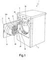
Figures 1 and2 ,number 1 indicates as a whole an electric household appliance, in particular a home laundry drier, substantially comprising a preferably, though not necessarily, parallelepiped-shaped casing 2; adrum 3 for housing the laundry to be dried, and which is housed in axially rotating manner and preferably, though not necessarily, horizontally insidecasing 2, directly facing a laundry loading/unloadingopening 2a formed in the front face ofcasing 2; adoor 4 hinged to the front face ofcasing 2 to rotate to and from a workposition closing opening 2a in the front face and sealingdrum 3; and an open-circuit, hot-air generator 5 housed insidecasing 2 to circulate hot, dry air insidedrum 3 and over the laundry inside the drum to dry the laundry rapidly. - Drier 1 also comprises an
electric motor 7 or similar for rotatingdrum 3 about its longitudinal axis L, preferably, though not necessarily, inside a dryingtub 6 housed insidecasing 2. In theFigure 1 example, longitudinal axis L coincides with the longitudinal axis of dryingtub 6. - With reference to
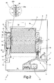
Figure 2 , open-circuit, hot-air generator 5 provides for gradually drawing in air fromoutside drum 3; heating the drawn-in air to a predetermined temperature; and drawing the damp air out ofdrum 3. - In other words, hot-
air generator 5 provides for continually drawing in outside air, heating and feeding it intodrum 3 to rapidly dry the laundry inside the drum, and exhausting the damp air fromdrum 3. - Hot-
air generator 5 substantially comprises: anair intake manifold 8 having a first end connected to the rear wall ofdrum 3, and a second end connected to anair inlet 9 formed preferably, though not necessarily, incasing 2; an electric heating element 10 (in the example shown, a resistor) located alongintake manifold 8 to rapidly heat the airflow throughinlet 9; anexhaust manifold 11 having a first end connected preferably, though not necessarily, to the front wall ofdrum 3, and a second end connected to anexhaust outlet 12 preferably, though not necessarily, in the front face ofcasing 2; and acentrifugal fan 13 located alongexhaust manifold 11 to produce, insideintake manifold 8 andexhaust manifold 11, an airflow, which flows throughdrum 3 and over the laundry inside the drum, and is exhausted to the outside. -
Centrifugal fan 13 is connected by a drive mechanism (shown by the dash line) toelectric motor 7, which rotates bothfan 13 anddrum 3 about respective axes of rotation as a function of control signals Sp generated by acontrol unit 14 during a user-selected drying cycle. - Drier 1 also comprises a
steam generator 15, which, as a function of control signals Sp generated bycontrol unit 14, feeds a steam jet intodrum 3 to eliminate or at any rate greatly reduce creasing of the fabrics during the drying cycle. -
Casing 2, dryingtub 6,drum 3,electric motor 7, andsteam generator 15 are commonly used parts in the industry and therefore not described in detail. - With reference to
Figure 2 ,exhaust manifold 11 comprises afirst manifold portion 16 extending insidecasing 2; and asecond manifold portion 17 fixed stably todoor 4 and designed to connect tofirst portion 16, whendoor 4 closes opening 2a, to connectfirst portion 16 todrum 3. - In the
Figure 2 and3 example,first manifold portion 16 preferably, though not necessarily, extends inside the front wall ofcasing 2, and has one end, i.e. its outlet, connected toexhaust outlet 12, and the opposite end, i.e. its inlet, connected to anopening 18 formed in anannular portion 35 ofcasing 2 defining the peripheral edge of opening 2a ofdrier 1 forhousing door 4. - More specifically,
centrifugal fan 13 is located alongfirst manifold portion 16, downstream fromsecond portion 17 along the air/steam flow path fromdrum 3 toexhaust outlet 12. -
Second portion 17 ofexhaust manifold 11 is defined by a substantially cylindrical box member orshell 21, which projects from the inner face ofdoor 4, extends through opening 2a, and projects partly insidedrum 3. - More specifically, with reference to
Figures 1 ,2 and3 ,shell 21 comprises afront wall 22 positioned facingdrum 3 whendoor 4 closes opening 2a, and in turn comprising a perforatedcentral portion 22a through which the air/steam indrum 3 flows to the inlet ofexhaust manifold 11. - More specifically, the
lateral wall 23 ofshell 21 has aslit 24 which, whendoor 4 closes opening 2a, is positioned facing opening 18 to connectsecond manifold portion 17 to the inlet offirst manifold portion 16, and so allow the air/steam flowing alongsecond portion 17 to flow freely intofirst portion 16 and out to the outside. - Unlike known open-circuit, hot-air generators, open-circuit, hot-
air generator 5 ofdrier 1 comprises shutter means 30 for selectively opening/closing exhaust manifold 11 (Figures 2 ,3 ) to allow/prevent free outflow of the air/steam fromdrum 3. - In other words, shutter means 30 selectively
close exhaust manifold 11 at the crease-removing stage to prevent the steam insidedrum 3 from flowing freely alongexhaust manifold 11 to the outside (Figure 3 ). - More specifically, in the example shown in
Figures 1 ,2 ,3 ,4, 5 , shutter means 30 comprise ashutter plate 25 mounted on theinner surface 22b offront wall 22 to move between an open position (shown schematically inFigure 2 ) - in which the air/steam indrum 3 flows freely throughperforated portion 22a offront wall 22 into exhaust manifold 11 - and a closed position (shown schematically inFigure 3 ) - in which the holes in central perforatedportion 22a are closed completely to prevent the air/steam indrum 3 from flowing freely to the outside alongexhaust manifold 11. - In the
Figure 2 example,shutter plate 25 is fitted movably toinner surface 22b offront wall 22, and is defined by a plate having a number of central holes which, whenshutter plate 25 is in the open position, are aligned with the holes in perforatedportion 22a offront wall 22. - Conversely, when
shutter plate 25 is in the closed position (Figure 3 ), the holes in the shutter plate are offset with respect to, and so close, the holes in perforatedportion 22a offront wall 22. - In the
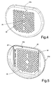
Figure 4 and 5 example,shutter plate 25 is mounted to slide along twolateral rails 26 on the inner surface offront wall 22, and has acentral operating tab 36 projecting towardsdrum 3 through a slot formed throughfront wall 22, to allow the user to moveshutter plate 25 manually between the open and closed position. - In the example shown, to activate the crease-removing function, the user moves
shutter plate 25 manually from the open to the closedposition using tab 36, thus closingexhaust manifold 11 and so preventing steam exhaust fromdrum 3 by centrifugal fan 13 (Figure 3 ), which nevertheless remains operative. - Conversely, to activate the drying function, the user moves
shutter plate 25 manually from the closed to the open position (Figure 2 ), thus openingexhaust manifold 11, so that the damp air is exhausted completely fromdrum 3 bycentrifugal fan 13. - In a first variation shown in
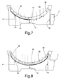
Figures 6 ,7 and 8 , shutter means 30 comprise aflap 32 fitted, at opening 18, toannular portion 35 ofcasing 2 defining the inner peripheral edge of opening 2a ofdrier 1, and which slides between an open position (shown schematically inFigures 6 ,7 ) allowing free air/steam flow fromdrum 3 toexhaust manifold 11, and a closed position (shown schematically inFigure 8 ) closing opening 18 to prevent air/steam flow fromdrum 3 toexhaust manifold 11. - More specifically, in the closed position, flap 32 seals opening 18 to prevent free air/steam flow from
second portion 17 tofirst portion 16; whereas, in the open position,flap 32 is shifted to the side of opening 18 to fully open and connect opening 18 to slit 24 inshell 21, and so allow free air/steam flow fromsecond portion 17 tofirst portion 16 of the exhaust manifold. - In a second variation shown in
Figure 9 , shutter means 30 comprise aflap 33 fitted, atslit 24, tolateral wall 23 ofshell 21, and which slides between an open position openingslit 24 and allowing free air/steam flow fromdrum 3 toexhaust manifold 11, and a closed position closingslit 24 to prevent air/steam flow fromdrum 3 tofirst portion 16 ofexhaust manifold 11. - More specifically, in the closed position,
flap 33 seals slit 24; whereas, in the open position,flap 33 is positioned, onlateral wall 23 ofshell 21, to the side ofslit 24 to fully open and connectslit 24 to opening 18 inannular portion 35 ofcasing 2. - To simplify user operation, and prevent misuse, of shutter means 30, hot-
air generator 5 may comprise a sensor 31 (Figures 2 ,3 ,7, 8 ) for determining the open/closed position of shutter means 30, and which, on detecting a closed position of shutter means 30, preventscontrol unit 14 from activating a drying cycle, and conversely, on detecting an open position of shutter means 30, preventscontrol unit 14 from activating a crease-removing cycle. - In the example shown,
sensor 31 may conveniently comprise a microswitch, which switches from one on/off state to the other when shutter means 30 are set to the open or closed position. - In the
Figure 2 and3 example,sensor 31 is located onwall 22 ofshell 21, and is switched byshutter plate 25 moving into a given open/closed position. - In the
Figure 7 and 8 example,sensor 31 is located onannular portion 35, and is switched byflap 32 moving into a given open/closed position; and, in theFigure 9 example,sensor 31 is located onlateral wall 23 ofshell 21, and is switched byflap 33 moving into a given open/closed position.Sensor 31 may obviously also be located directly onflap 33 or in any other position in which it is switched by a change in position offlap 33. - To activate the drying function, the user sets shutter means 30 to the open position opening
exhaust manifold 11, and activates a drying cycle using selector means (not shown). At which point, by means ofsensor 31,control unit 14 determines whether or not shutter means 30 are in the open position, and, if they are not, disables the user-set drying cycle. - Conversely, on determining shutter means 30 are in the open position,
control unit 14 activates hot-air generator 5 and, simultaneously,electric motor 7, which rotatesdrum 3 andcentrifugal fan 13, which expels the damp air along the, in this case, fullyopen exhaust manifold 11. - To activate the crease-removing function, the user sets shutter means 30 to the closed position closing
exhaust manifold 11, and activates a crease-removing cycle using selector means (not shown). - At which point, by means of
sensor 31,control unit 14 determines whether or not shutter means 30 are in the closed position, and, if they are not, disables the user-set crease-removing cycle. - Conversely, on determining shutter means 30 are in the closed position,
control unit 14 activatessteam generator 15 and, simultaneously,electric motor 7, which rotates bothdrum 3 andcentrifugal fan 13, which, in this case, expels no steam from the drying tub, by virtue ofexhaust manifold 11 being closed. - The drier described has the major advantage of employing a single electric motor for driving both the ventilation device and the laundry drum, thus maintaining the cost-saving advantages of known driers with an open-circuit, hot-air generator, while at the same time implementing the crease-removing function in an extremely straightforward manner, with no immediate steam exhaust from
laundry drum 3, even with the fan running. - Moreover,
sensor 31 safeguards against user selection and activation of drying or crease-removing cycles incompatible with the position of shutter means 30. - Without
sensor 31, in fact, activation of a drying cycle with shutter means 30 in the closed position could result in overheating and damage to the laundry. Disabling of the drying cycle bycontrol unit 14 on the basis of information fromsensor 31, on the other hand, conveniently eliminates any risk of accidental damage to the fabrics inside the laundry drum. - Clearly, changes may be made to
electric household appliance 1 as described herein without, however, departing from the scope of the present invention.
Claims (9)
- An electric household appliance (1) comprising a casing (2); a rotary drum (3) housing laundry to be dried and mounted for rotation about its longitudinal axis (L); a door (4) which rotates to and from a work position closing an opening (2a) in said casing (2) to close said drum (3); hot-air generating means (5) for circulating hot air inside the drum (3); steam generating means (15) for circulating a steam jet inside the drum (3) ; and at least one exhaust manifold (11) communicating with said drum (3) to allow outflow of air/steam from said drum (3);
said electric household appliance (1) being characterized by comprising shutter means (30) for selectively permitting or preventing outflow of air/steam from said drum (3). - An electric household appliance (1) as claimed in Claim 1, wherein said shutter means (30) are interposed between said drum (3) and said exhaust manifold (11).
- An electric household appliance (1) as claimed in Claim 1, wherein said exhaust manifold (11) comprises a first manifold portion (16) extending inside said casing (2) and having an inlet substantially facing the lateral wall (23) of the door (4) ; and a second manifold portion (17) fitted to said door (4) and designed to communicate with the inlet of said first manifold portion (16) when said door (4) closes said opening (2a); said shutter means (30) selectively opening/closing said second manifold portion (17) to permit or prevent free flow of air or steam from said drum (3) to said first manifold portion (16).
- An electric household appliance (1) as claimed in Claim 3, wherein said second manifold portion (17) comprises a shell (21) fixed stably to said door (4) and having a perforated wall (22) facing said drum (3); said shutter means (30) comprising a shutter plate (25) fitted to said perforated wall (22) to move between an open position, in which air/steam flows freely from the drum (3) to the exhaust manifold (11) through the holes in said perforated wall (22), and a closed position, in which the shutter plate (25) closes the holes in said perforated wall (22) to prevent free outflow of air/steam from the drum (3) through said exhaust manifold (11).
- An electric household appliance (1) as claimed in Claim 3, wherein said second manifold portion (17) comprises a shell (21) fixed stably to said door (4) and having a perforated wall (22) facing said drum (3), and a lateral wall (23) having a through slit (24) communicating with the inlet of the first manifold portion (16); said shutter means (30) comprising a flap (33) fitted to said lateral wall (23) of said shell (21), at said slit (24), to move between an open position, in which air/steam flows freely from the drum (3) into the first manifold portion (16) through said slit (24), and a closed position, in which said flap (33) seals the slit (24) to prevent free outflow of air/steam from the drum (3) through said first manifold portion (16).
- An electric household appliance (1) as claimed in Claim 3, wherein said second manifold portion (17) comprises a shell (21) fitted to the inside of said door (4) and having a perforated wall (22) facing said drum (3), and a lateral wall (23) having a through slit (24) communicating with the inlet of the first manifold portion (16) of the exhaust manifold (11); the inlet of the first manifold portion (16) being defined by an opening (18) formed in the annular edge (35) of the casing (2) housing said door (4) ; said shutter means (30) comprising a flap (32) fitted to said annular edge (35) to move between an open position, in which air/steam flows freely from the drum (3) into the first manifold portion (16) through said opening (18), and a closed position, in which said flap (32) seals the opening (18) to prevent free outflow of air/steam from the drum (3) through said first manifold portion (16).
- An electric household appliance (1) as claimed in any one of the foregoing Claims, and comprising sensor means (31) for determining the closed/open position of said shutter means (30).
- An electric household appliance (1) as claimed in Claim 7, and comprising a control unit (14) for selectively enabling/disabling said hot-air generating means (5) or said steam generating means (15) as a function of the open/closed position of said shutter means (30) determined by said sensor means (31).
- An electric household appliance (1) as claimed in any one of the foregoing Claims, and comprising at least one centrifugal fan (13) located along said exhaust manifold (11), downstream from said shutter means (30), to expel air/steam from the drum (3); and an electric motor (7) for rotating both the centrifugal fan (13) and said drum (3) about respective axes.
Priority Applications (10)
| Application Number | Priority Date | Filing Date | Title |
|---|---|---|---|
| AT07108567T ATE448350T1 (en) | 2007-05-21 | 2007-05-21 | HOUSEHOLD ELECTRICAL APPLIANCE |
| ES07108567T ES2334465T3 (en) | 2007-05-21 | 2007-05-21 | APPLIANCE APPLIANCE. |
| DE602007003199T DE602007003199D1 (en) | 2007-05-21 | 2007-05-21 | Electric household appliance |
| EP07108567A EP1995371B1 (en) | 2007-05-21 | 2007-05-21 | Electric household appliance |
| PL07108567T PL1995371T3 (en) | 2007-05-21 | 2007-05-21 | Electric household appliance |
| CN2008800136771A CN101668892B (en) | 2007-05-21 | 2008-05-13 | Electric household appliance |
| MX2009012301A MX2009012301A (en) | 2007-05-21 | 2008-05-13 | Electric household appliance. |
| BRPI0811602-4A BRPI0811602A2 (en) | 2007-05-21 | 2008-05-13 | Home appliance |
| PCT/EP2008/003811 WO2008141750A1 (en) | 2007-05-21 | 2008-05-13 | Electric household appliance |
| US12/593,950 US8272144B2 (en) | 2007-05-21 | 2008-05-13 | Electric household appliance |
Applications Claiming Priority (1)
| Application Number | Priority Date | Filing Date | Title |
|---|---|---|---|
| EP07108567A EP1995371B1 (en) | 2007-05-21 | 2007-05-21 | Electric household appliance |
Publications (2)
| Publication Number | Publication Date |
|---|---|
| EP1995371A1 true EP1995371A1 (en) | 2008-11-26 |
| EP1995371B1 EP1995371B1 (en) | 2009-11-11 |
Family
ID=38651249
Family Applications (1)
| Application Number | Title | Priority Date | Filing Date |
|---|---|---|---|
| EP07108567A Not-in-force EP1995371B1 (en) | 2007-05-21 | 2007-05-21 | Electric household appliance |
Country Status (10)
| Country | Link |
|---|---|
| US (1) | US8272144B2 (en) |
| EP (1) | EP1995371B1 (en) |
| CN (1) | CN101668892B (en) |
| AT (1) | ATE448350T1 (en) |
| BR (1) | BRPI0811602A2 (en) |
| DE (1) | DE602007003199D1 (en) |
| ES (1) | ES2334465T3 (en) |
| MX (1) | MX2009012301A (en) |
| PL (1) | PL1995371T3 (en) |
| WO (1) | WO2008141750A1 (en) |
Cited By (2)
| Publication number | Priority date | Publication date | Assignee | Title |
|---|---|---|---|---|
| US20110041353A1 (en) * | 2008-04-29 | 2011-02-24 | BSH Bosch und Siemens Hausgeräte GmbH | Vented dryer having counter-flowing air and method for the operation thereof |
| EP2642012A1 (en) | 2012-03-22 | 2013-09-25 | Electrolux Home Products Corporation N.V. | Laundry machine and method of laundry treatment in a laundry machine |
Families Citing this family (8)
| Publication number | Priority date | Publication date | Assignee | Title |
|---|---|---|---|---|
| DE102007007354B4 (en) | 2006-02-20 | 2013-10-10 | Lg Electronics Inc. | Clothes dryer and method of control |
| KR100830514B1 (en) | 2006-06-12 | 2008-05-21 | 엘지전자 주식회사 | laundry dryer and method for controlling the same |
| US7997006B2 (en) * | 2007-01-12 | 2011-08-16 | Lg Electronics Inc. | Laundry machine and control method thereof |
| US8104191B2 (en) | 2008-07-31 | 2012-01-31 | Electrolux Home Products, Inc. | Laundry dryer providing moisture application during tumbling and reduced airflow |
| US20120005915A1 (en) * | 2009-04-02 | 2012-01-12 | Lg Electronics Inc. | Clothes dryer having a steam generator using a hot air heater |
| US9109317B2 (en) | 2009-08-21 | 2015-08-18 | Whirlpool Corporation | Controlled moisture removal in a laundry treating appliance |
| CN107366143A (en) * | 2017-09-14 | 2017-11-21 | 无锡市强力干燥设备厂 | Laundry drum dryer |
| US20190218701A1 (en) * | 2018-01-12 | 2019-07-18 | Whirlpool Corporation | Laundry treating appliance with vent |
Citations (7)
| Publication number | Priority date | Publication date | Assignee | Title |
|---|---|---|---|---|
| US2873539A (en) * | 1958-02-27 | 1959-02-17 | Gen Electric | Clothes dryer with clothes odorizing means |
| GB2143935A (en) * | 1983-07-25 | 1985-02-20 | Hotpoint Ltd | Tumbler dryer |
| GB2346678A (en) * | 1998-12-23 | 2000-08-16 | Electrolux Zanussi Elettrodome | Rotary drum drier with door having a dispenser containing co-adjuvant substances |
| EP1441058A1 (en) * | 2003-01-25 | 2004-07-28 | Electrolux Home Products Corporation N.V. | Laundry dryer with an air circulation mode and process of treatment of laundry |
| EP1666655A2 (en) * | 2004-12-02 | 2006-06-07 | Samsung Electronics Co., Ltd. | Eliminating wrinkles in laundry |
| WO2006101358A1 (en) * | 2005-03-25 | 2006-09-28 | Lg Electronics Inc. | Laundry machine |
| US20070006484A1 (en) * | 2002-12-20 | 2007-01-11 | Harald Moschuetz | Clothes dryer and method for removing odours from textiles |
Family Cites Families (7)
| Publication number | Priority date | Publication date | Assignee | Title |
|---|---|---|---|---|
| NL135382C (en) * | 1961-10-03 | |||
| US3544207A (en) * | 1968-01-03 | 1970-12-01 | Bell & Howell Co | Shutter control mechanism |
| JPS6429295A (en) * | 1987-07-27 | 1989-01-31 | Matsushita Seiko Kk | Small clothing drying case |
| DE10302866B4 (en) | 2003-01-25 | 2010-08-12 | Electrolux Home Products Corporation N.V. | Dryer with a device for spraying additives and method therefor |
| US7171821B2 (en) * | 2004-04-30 | 2007-02-06 | Thermo King Corporation | Temperature control unit having a vent arrangement |
| KR100717457B1 (en) * | 2004-10-22 | 2007-05-14 | 엘지전자 주식회사 | a drum-typed washing machine |
| WO2006126815A2 (en) * | 2005-05-23 | 2006-11-30 | Lg Electronics, Inc. | Dryer and method for controlling the same |
-
2007
- 2007-05-21 ES ES07108567T patent/ES2334465T3/en active Active
- 2007-05-21 PL PL07108567T patent/PL1995371T3/en unknown
- 2007-05-21 AT AT07108567T patent/ATE448350T1/en not_active IP Right Cessation
- 2007-05-21 DE DE602007003199T patent/DE602007003199D1/en active Active
- 2007-05-21 EP EP07108567A patent/EP1995371B1/en not_active Not-in-force
-
2008
- 2008-05-13 WO PCT/EP2008/003811 patent/WO2008141750A1/en active Application Filing
- 2008-05-13 CN CN2008800136771A patent/CN101668892B/en not_active Expired - Fee Related
- 2008-05-13 BR BRPI0811602-4A patent/BRPI0811602A2/en not_active IP Right Cessation
- 2008-05-13 US US12/593,950 patent/US8272144B2/en active Active
- 2008-05-13 MX MX2009012301A patent/MX2009012301A/en active IP Right Grant
Patent Citations (7)
| Publication number | Priority date | Publication date | Assignee | Title |
|---|---|---|---|---|
| US2873539A (en) * | 1958-02-27 | 1959-02-17 | Gen Electric | Clothes dryer with clothes odorizing means |
| GB2143935A (en) * | 1983-07-25 | 1985-02-20 | Hotpoint Ltd | Tumbler dryer |
| GB2346678A (en) * | 1998-12-23 | 2000-08-16 | Electrolux Zanussi Elettrodome | Rotary drum drier with door having a dispenser containing co-adjuvant substances |
| US20070006484A1 (en) * | 2002-12-20 | 2007-01-11 | Harald Moschuetz | Clothes dryer and method for removing odours from textiles |
| EP1441058A1 (en) * | 2003-01-25 | 2004-07-28 | Electrolux Home Products Corporation N.V. | Laundry dryer with an air circulation mode and process of treatment of laundry |
| EP1666655A2 (en) * | 2004-12-02 | 2006-06-07 | Samsung Electronics Co., Ltd. | Eliminating wrinkles in laundry |
| WO2006101358A1 (en) * | 2005-03-25 | 2006-09-28 | Lg Electronics Inc. | Laundry machine |
Cited By (6)
| Publication number | Priority date | Publication date | Assignee | Title |
|---|---|---|---|---|
| US20110041353A1 (en) * | 2008-04-29 | 2011-02-24 | BSH Bosch und Siemens Hausgeräte GmbH | Vented dryer having counter-flowing air and method for the operation thereof |
| US8528226B2 (en) * | 2008-04-29 | 2013-09-10 | Bsh Bosch Und Siemens Hausgeraete Gmbh | Vented dryer having counter-flowing air and method for the operation thereof |
| EP2642012A1 (en) | 2012-03-22 | 2013-09-25 | Electrolux Home Products Corporation N.V. | Laundry machine and method of laundry treatment in a laundry machine |
| WO2013139686A1 (en) * | 2012-03-22 | 2013-09-26 | Electrolux Home Products Corporation N.V. | Laundry machine and method of laundry treatment in a laundry machine |
| CN104204331A (en) * | 2012-03-22 | 2014-12-10 | 伊莱克斯家用产品股份有限公司 | Laundry machine and method of laundry treatment in a laundry machine |
| CN104204331B (en) * | 2012-03-22 | 2017-04-26 | 伊莱克斯家用产品股份有限公司 | Laundry machine and method of laundry treatment in a laundry machine |
Also Published As
| Publication number | Publication date |
|---|---|
| US8272144B2 (en) | 2012-09-25 |
| DE602007003199D1 (en) | 2009-12-24 |
| EP1995371B1 (en) | 2009-11-11 |
| PL1995371T3 (en) | 2010-04-30 |
| CN101668892B (en) | 2011-05-18 |
| BRPI0811602A2 (en) | 2015-08-04 |
| MX2009012301A (en) | 2009-12-03 |
| ES2334465T3 (en) | 2010-03-10 |
| ATE448350T1 (en) | 2009-11-15 |
| US20100115790A1 (en) | 2010-05-13 |
| WO2008141750A1 (en) | 2008-11-27 |
| CN101668892A (en) | 2010-03-10 |
Similar Documents
| Publication | Publication Date | Title |
|---|---|---|
| EP1995371B1 (en) | Electric household appliance | |
| KR100662473B1 (en) | Laundry dryer with steam generator | |
| EP1951948B1 (en) | Steam generator and laundry dryer having the same and controlling method thereof | |
| US8250777B2 (en) | Device of supplying water for laundry dryer and method for controlling the same | |
| KR101328920B1 (en) | laundry dryer | |
| EP2039823B1 (en) | Laundry machine | |
| KR100866884B1 (en) | Controlling method of a clothes dryer for detecting an amount of laundry put therein and a clothes dryer with the same | |
| KR20090030899A (en) | Laundry machine | |
| KR100640788B1 (en) | Laundry dryer with steam generator | |
| KR20060061974A (en) | Apparatus for remove wrinkles of clothes and method thereof | |
| KR101208532B1 (en) | laundry dryer | |
| EP2634301B1 (en) | Household laundry washing and drying machine with a condensing device and method of operating this machine | |
| KR100672439B1 (en) | Laundry dryer with steam generator | |
| KR100740836B1 (en) | laundry dryer with steam generator | |
| KR100662472B1 (en) | Laundry dryer with steam generator | |
| EP2280114B1 (en) | Clothes dryer having liquid injection nozzle | |
| KR100640811B1 (en) | Device of supplying water for laundry dryer and method for controlling the same | |
| KR100672437B1 (en) | Steam generator and laundry dryer having the same | |
| KR100833866B1 (en) | Steam laundry dryer | |
| JP4383960B2 (en) | Washing machine with drying function | |
| KR100672438B1 (en) | Laundry dryer with steam generator | |
| KR100734371B1 (en) | laundry dryer and method for controlling the same | |
| JP5597373B2 (en) | Clothes dryer | |
| KR101208534B1 (en) | laundry dryer | |
| KR101015864B1 (en) | Drum type washing machine with the consolidated single heater |
Legal Events
| Date | Code | Title | Description |
|---|---|---|---|
| PUAI | Public reference made under article 153(3) epc to a published international application that has entered the european phase |
Free format text: ORIGINAL CODE: 0009012 |
|
| AK | Designated contracting states |
Kind code of ref document: A1 Designated state(s): AT BE BG CH CY CZ DE DK EE ES FI FR GB GR HU IE IS IT LI LT LU LV MC MT NL PL PT RO SE SI SK TR |
|
| AX | Request for extension of the european patent |
Extension state: AL BA HR MK RS |
|
| GRAP | Despatch of communication of intention to grant a patent |
Free format text: ORIGINAL CODE: EPIDOSNIGR1 |
|
| 17P | Request for examination filed |
Effective date: 20090504 |
|
| AKX | Designation fees paid |
Designated state(s): AT BE BG CH CY CZ DE DK EE ES FI FR GB GR HU IE IS IT LI LT LU LV MC MT NL PL PT RO SE SI SK TR |
|
| GRAS | Grant fee paid |
Free format text: ORIGINAL CODE: EPIDOSNIGR3 |
|
| GRAA | (expected) grant |
Free format text: ORIGINAL CODE: 0009210 |
|
| AK | Designated contracting states |
Kind code of ref document: B1 Designated state(s): AT BE BG CH CY CZ DE DK EE ES FI FR GB GR HU IE IS IT LI LT LU LV MC MT NL PL PT RO SE SI SK TR |
|
| REG | Reference to a national code |
Ref country code: GB Ref legal event code: FG4D |
|
| REG | Reference to a national code |
Ref country code: CH Ref legal event code: EP |
|
| REG | Reference to a national code |
Ref country code: IE Ref legal event code: FG4D |
|
| REF | Corresponds to: |
Ref document number: 602007003199 Country of ref document: DE Date of ref document: 20091224 Kind code of ref document: P |
|
| REG | Reference to a national code |
Ref country code: ES Ref legal event code: FG2A Ref document number: 2334465 Country of ref document: ES Kind code of ref document: T3 |
|
| NLV1 | Nl: lapsed or annulled due to failure to fulfill the requirements of art. 29p and 29m of the patents act | ||
| LTIE | Lt: invalidation of european patent or patent extension |
Effective date: 20091111 |
|
| PG25 | Lapsed in a contracting state [announced via postgrant information from national office to epo] |
Ref country code: LT Free format text: LAPSE BECAUSE OF FAILURE TO SUBMIT A TRANSLATION OF THE DESCRIPTION OR TO PAY THE FEE WITHIN THE PRESCRIBED TIME-LIMIT Effective date: 20091111 Ref country code: PT Free format text: LAPSE BECAUSE OF FAILURE TO SUBMIT A TRANSLATION OF THE DESCRIPTION OR TO PAY THE FEE WITHIN THE PRESCRIBED TIME-LIMIT Effective date: 20100311 Ref country code: FI Free format text: LAPSE BECAUSE OF FAILURE TO SUBMIT A TRANSLATION OF THE DESCRIPTION OR TO PAY THE FEE WITHIN THE PRESCRIBED TIME-LIMIT Effective date: 20091111 Ref country code: SE Free format text: LAPSE BECAUSE OF FAILURE TO SUBMIT A TRANSLATION OF THE DESCRIPTION OR TO PAY THE FEE WITHIN THE PRESCRIBED TIME-LIMIT Effective date: 20091111 Ref country code: IS Free format text: LAPSE BECAUSE OF FAILURE TO SUBMIT A TRANSLATION OF THE DESCRIPTION OR TO PAY THE FEE WITHIN THE PRESCRIBED TIME-LIMIT Effective date: 20100311 |
|
| REG | Reference to a national code |
Ref country code: PL Ref legal event code: T3 |
|
| PG25 | Lapsed in a contracting state [announced via postgrant information from national office to epo] |
Ref country code: SI Free format text: LAPSE BECAUSE OF FAILURE TO SUBMIT A TRANSLATION OF THE DESCRIPTION OR TO PAY THE FEE WITHIN THE PRESCRIBED TIME-LIMIT Effective date: 20091111 Ref country code: CY Free format text: LAPSE BECAUSE OF FAILURE TO SUBMIT A TRANSLATION OF THE DESCRIPTION OR TO PAY THE FEE WITHIN THE PRESCRIBED TIME-LIMIT Effective date: 20091111 Ref country code: LV Free format text: LAPSE BECAUSE OF FAILURE TO SUBMIT A TRANSLATION OF THE DESCRIPTION OR TO PAY THE FEE WITHIN THE PRESCRIBED TIME-LIMIT Effective date: 20091111 |
|
| PG25 | Lapsed in a contracting state [announced via postgrant information from national office to epo] |
Ref country code: AT Free format text: LAPSE BECAUSE OF FAILURE TO SUBMIT A TRANSLATION OF THE DESCRIPTION OR TO PAY THE FEE WITHIN THE PRESCRIBED TIME-LIMIT Effective date: 20091111 Ref country code: BE Free format text: LAPSE BECAUSE OF FAILURE TO SUBMIT A TRANSLATION OF THE DESCRIPTION OR TO PAY THE FEE WITHIN THE PRESCRIBED TIME-LIMIT Effective date: 20091111 |
|
| PG25 | Lapsed in a contracting state [announced via postgrant information from national office to epo] |
Ref country code: EE Free format text: LAPSE BECAUSE OF FAILURE TO SUBMIT A TRANSLATION OF THE DESCRIPTION OR TO PAY THE FEE WITHIN THE PRESCRIBED TIME-LIMIT Effective date: 20091111 Ref country code: DK Free format text: LAPSE BECAUSE OF FAILURE TO SUBMIT A TRANSLATION OF THE DESCRIPTION OR TO PAY THE FEE WITHIN THE PRESCRIBED TIME-LIMIT Effective date: 20091111 Ref country code: BG Free format text: LAPSE BECAUSE OF FAILURE TO SUBMIT A TRANSLATION OF THE DESCRIPTION OR TO PAY THE FEE WITHIN THE PRESCRIBED TIME-LIMIT Effective date: 20100211 Ref country code: RO Free format text: LAPSE BECAUSE OF FAILURE TO SUBMIT A TRANSLATION OF THE DESCRIPTION OR TO PAY THE FEE WITHIN THE PRESCRIBED TIME-LIMIT Effective date: 20091111 |
|
| PG25 | Lapsed in a contracting state [announced via postgrant information from national office to epo] |
Ref country code: SK Free format text: LAPSE BECAUSE OF FAILURE TO SUBMIT A TRANSLATION OF THE DESCRIPTION OR TO PAY THE FEE WITHIN THE PRESCRIBED TIME-LIMIT Effective date: 20091111 Ref country code: CZ Free format text: LAPSE BECAUSE OF FAILURE TO SUBMIT A TRANSLATION OF THE DESCRIPTION OR TO PAY THE FEE WITHIN THE PRESCRIBED TIME-LIMIT Effective date: 20091111 |
|
| PLBE | No opposition filed within time limit |
Free format text: ORIGINAL CODE: 0009261 |
|
| STAA | Information on the status of an ep patent application or granted ep patent |
Free format text: STATUS: NO OPPOSITION FILED WITHIN TIME LIMIT |
|
| 26N | No opposition filed |
Effective date: 20100812 |
|
| PG25 | Lapsed in a contracting state [announced via postgrant information from national office to epo] |
Ref country code: GR Free format text: LAPSE BECAUSE OF FAILURE TO SUBMIT A TRANSLATION OF THE DESCRIPTION OR TO PAY THE FEE WITHIN THE PRESCRIBED TIME-LIMIT Effective date: 20100212 |
|
| PG25 | Lapsed in a contracting state [announced via postgrant information from national office to epo] |
Ref country code: MC Free format text: LAPSE BECAUSE OF NON-PAYMENT OF DUE FEES Effective date: 20100531 |
|
| PG25 | Lapsed in a contracting state [announced via postgrant information from national office to epo] |
Ref country code: IT Free format text: LAPSE BECAUSE OF NON-PAYMENT OF DUE FEES Effective date: 20100521 |
|
| PG25 | Lapsed in a contracting state [announced via postgrant information from national office to epo] |
Ref country code: IE Free format text: LAPSE BECAUSE OF NON-PAYMENT OF DUE FEES Effective date: 20100521 Ref country code: MT Free format text: LAPSE BECAUSE OF FAILURE TO SUBMIT A TRANSLATION OF THE DESCRIPTION OR TO PAY THE FEE WITHIN THE PRESCRIBED TIME-LIMIT Effective date: 20091111 |
|
| REG | Reference to a national code |
Ref country code: CH Ref legal event code: PL |
|
| PG25 | Lapsed in a contracting state [announced via postgrant information from national office to epo] |
Ref country code: LI Free format text: LAPSE BECAUSE OF NON-PAYMENT OF DUE FEES Effective date: 20110531 Ref country code: CH Free format text: LAPSE BECAUSE OF NON-PAYMENT OF DUE FEES Effective date: 20110531 |
|
| REG | Reference to a national code |
Ref country code: FR Ref legal event code: CA Effective date: 20120116 |
|
| PG25 | Lapsed in a contracting state [announced via postgrant information from national office to epo] |
Ref country code: LU Free format text: LAPSE BECAUSE OF NON-PAYMENT OF DUE FEES Effective date: 20100521 Ref country code: NL Free format text: LAPSE BECAUSE OF FAILURE TO SUBMIT A TRANSLATION OF THE DESCRIPTION OR TO PAY THE FEE WITHIN THE PRESCRIBED TIME-LIMIT Effective date: 20091111 Ref country code: HU Free format text: LAPSE BECAUSE OF FAILURE TO SUBMIT A TRANSLATION OF THE DESCRIPTION OR TO PAY THE FEE WITHIN THE PRESCRIBED TIME-LIMIT Effective date: 20100512 |
|
| PG25 | Lapsed in a contracting state [announced via postgrant information from national office to epo] |
Ref country code: TR Free format text: LAPSE BECAUSE OF FAILURE TO SUBMIT A TRANSLATION OF THE DESCRIPTION OR TO PAY THE FEE WITHIN THE PRESCRIBED TIME-LIMIT Effective date: 20091111 |
|
| PGFP | Annual fee paid to national office [announced via postgrant information from national office to epo] |
Ref country code: ES Payment date: 20120525 Year of fee payment: 6 |
|
| PGFP | Annual fee paid to national office [announced via postgrant information from national office to epo] |
Ref country code: GB Payment date: 20130521 Year of fee payment: 7 Ref country code: DE Payment date: 20130522 Year of fee payment: 7 |
|
| PGFP | Annual fee paid to national office [announced via postgrant information from national office to epo] |
Ref country code: IT Payment date: 20130530 Year of fee payment: 7 Ref country code: FR Payment date: 20130603 Year of fee payment: 7 Ref country code: PL Payment date: 20130425 Year of fee payment: 7 |
|
| REG | Reference to a national code |
Ref country code: DE Ref legal event code: R119 Ref document number: 602007003199 Country of ref document: DE |
|
| GBPC | Gb: european patent ceased through non-payment of renewal fee |
Effective date: 20140521 |
|
| REG | Reference to a national code |
Ref country code: FR Ref legal event code: ST Effective date: 20150130 |
|
| REG | Reference to a national code |
Ref country code: DE Ref legal event code: R119 Ref document number: 602007003199 Country of ref document: DE Effective date: 20141202 |
|
| PG25 | Lapsed in a contracting state [announced via postgrant information from national office to epo] |
Ref country code: IT Free format text: LAPSE BECAUSE OF NON-PAYMENT OF DUE FEES Effective date: 20140521 Ref country code: DE Free format text: LAPSE BECAUSE OF NON-PAYMENT OF DUE FEES Effective date: 20141202 |
|
| PG25 | Lapsed in a contracting state [announced via postgrant information from national office to epo] |
Ref country code: FR Free format text: LAPSE BECAUSE OF NON-PAYMENT OF DUE FEES Effective date: 20140602 Ref country code: GB Free format text: LAPSE BECAUSE OF NON-PAYMENT OF DUE FEES Effective date: 20140521 |
|
| PG25 | Lapsed in a contracting state [announced via postgrant information from national office to epo] |
Ref country code: PL Free format text: LAPSE BECAUSE OF NON-PAYMENT OF DUE FEES Effective date: 20140521 |
|
| REG | Reference to a national code |
Ref country code: PL Ref legal event code: LAPE |
|
| REG | Reference to a national code |
Ref country code: ES Ref legal event code: FD2A Effective date: 20160205 |
|
| PG25 | Lapsed in a contracting state [announced via postgrant information from national office to epo] |
Ref country code: ES Free format text: LAPSE BECAUSE OF NON-PAYMENT OF DUE FEES Effective date: 20140522 |