EP1994892A1 - Instrument set for minimally invasive preparation of a bone nailing procedure - Google Patents
Instrument set for minimally invasive preparation of a bone nailing procedure Download PDFInfo
- Publication number
- EP1994892A1 EP1994892A1 EP08009307A EP08009307A EP1994892A1 EP 1994892 A1 EP1994892 A1 EP 1994892A1 EP 08009307 A EP08009307 A EP 08009307A EP 08009307 A EP08009307 A EP 08009307A EP 1994892 A1 EP1994892 A1 EP 1994892A1
- Authority
- EP
- European Patent Office
- Prior art keywords
- sleeve
- base sleeve
- instrument set
- set according
- bone
- Prior art date
- Legal status (The legal status is an assumption and is not a legal conclusion. Google has not performed a legal analysis and makes no representation as to the accuracy of the status listed.)
- Granted
Links
Images


Classifications
-
- A—HUMAN NECESSITIES
- A61—MEDICAL OR VETERINARY SCIENCE; HYGIENE
- A61B—DIAGNOSIS; SURGERY; IDENTIFICATION
- A61B17/00—Surgical instruments, devices or methods, e.g. tourniquets
- A61B17/16—Bone cutting, breaking or removal means other than saws, e.g. Osteoclasts; Drills or chisels for bones; Trepans
- A61B17/17—Guides or aligning means for drills, mills, pins or wires
- A61B17/1717—Guides or aligning means for drills, mills, pins or wires for applying intramedullary nails or pins
-
- A—HUMAN NECESSITIES
- A61—MEDICAL OR VETERINARY SCIENCE; HYGIENE
- A61B—DIAGNOSIS; SURGERY; IDENTIFICATION
- A61B17/00—Surgical instruments, devices or methods, e.g. tourniquets
- A61B17/34—Trocars; Puncturing needles
- A61B17/3417—Details of tips or shafts, e.g. grooves, expandable, bendable; Multiple coaxial sliding cannulas, e.g. for dilating
- A61B17/3421—Cannulas
-
- A—HUMAN NECESSITIES
- A61—MEDICAL OR VETERINARY SCIENCE; HYGIENE
- A61B—DIAGNOSIS; SURGERY; IDENTIFICATION
- A61B17/00—Surgical instruments, devices or methods, e.g. tourniquets
- A61B17/34—Trocars; Puncturing needles
- A61B17/3472—Trocars; Puncturing needles for bones, e.g. intraosseus injections
Definitions
- the invention relates to a set of instruments for minimally invasive preparation of a bone nailing.
- the set of instruments is intended primarily for a minimally invasive preparation of a bone nailing for thigh, lower leg and upper arm bone. In principle, however, it can also be used for the minimally invasive preparation of a nailing of other bones.
- the prior art are individual implantation aids, such as e.g. Tubular or tubular tissue protection instruments, which are provided with a handle and can be used to protect the soft tissues.
- tissue protection instruments e.g. Tubular or tubular tissue protection instruments
- small-caliber intramedullary nails which are preferably used in fracture treatment, where no medullary canal drilling is required, it can be operated with tissue-friendly.
- intramedullary nails which are particularly advantageous for secondary corrective measures, but also increasingly gaining importance in the fracture treatment, but in any case for intramedullary nails that require a preparation of the medullary space, ie a milling according to planning and not following the path of least resistance, so far there is no solution that meets the current requirements.
- a tissue protection in the form of a bent sheet or in the form of a patch on the bone sleeve is provided when using Markraumfräsern.
- These tools have many disadvantages.
- the space material When accessing the femur from the proximal, for example, the space material is distributed in the soft tissues and occasionally leads to disturbing ossifications.
- the spacer material In the case of access to the thighbone from distal, the spacer material has hitherto been distributed in the knee joint, which is likewise disadvantageous.
- the bone is first severed surgically into an entry-distant and an entry-proximal bone segment, unless there is already a continuity interruption.
- the milling of the entry-distant bone segment in the middle of the shaft must take place in many consecutive milling operations due to the usually hard diaphyseal bone structure. Since the cutters pass the entry-proximal bone segment with each change, and this passage often occurs at an unfavorable angle due to soft tissue, considerable correction losses have so far been caused by secondary milled cuts in the bone segment near the entry.
- the object underlying the invention is to provide a set of instruments, with which it is possible overall to realize a minimally invasive access route, to provide throughout the process for a substantial soft tissue protection, to avoid contamination by space material, precisely determine the nail entry point, the Precise to specify milling direction and thus the nail direction and to provide for a Aushülsung the cutting path of a bone segment near the entry of two to be connected by a nail bone segments.
- the end portion of the Dilatationshülse is advantageously a straight or slanted Kreiskegel- or truncated pyramid.
- a positional correction of the base sleeve is possible by the amount by which the pointed end of the oblique circular cone or truncated pyramid is eccentric in a controlled rotation of the dilation around the guide wire.
- the end portion of the dilation sleeve is a slanted circular cone or truncated pyramid and a correction is brought about by turning the dilatation sleeve, it tends soft tissue to turn back to the starting position. Since the dilatation sleeve can not be held at the end, the new, twisted position must be secured.
- a fixation extension which is elongated into the outlet opening and whose inner diameter is dimensioned for a sliding fit with the guide wire and whose outer surface has the shape of a polygon, for example a hexagon, in cross section.
- the reaction force which occurs when the base sleeve is driven in has a tendency to drive back the dilatation sleeve, as a result of which the contact with the bone and that caused by centering on the bone Guidewire set position could be lost.
- the safety projections may be formed by threads or circumferential planes lying in radial planes.
- the tool engagement end of the base sleeve is a ring extending radially outwardly therefrom, while the stop at the one end of the working sleeve may be a radially outwardly extending peripheral bead.
- the rigid guide wire has expediently a diameter of 2 to 5 mm, preferably 3 mm.
- the base sleeve may have an inner diameter of 6 to 20 mm, a wall thickness of 1 to 3 mm and preferably consist of implant steel.
- the instrument set can be supplemented by at least one impact instrument and / or an extraction tool for the base sleeve.
- the outer diameter of the working sleeves is matched to the inner diameter of the base sleeves or the next larger working sleeve, so that an axial sliding is possible.
- the inner diameters of the working sleeves are determined on the basis of the drills or milling cutters to be guided in them and according to the outer diameter of the nail used, in particular intramedullary nail.
- a plurality of diameter-matched working sleeves also of different lengths, can be placed in a base sleeve.
- the lengths of the base sleeves and dilatation sleeves are determined essentially dependent on the thicknesses of the soft tissues to be penetrated.
- the set of instruments consists of approximately 20 to 100 cases.
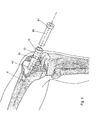
- Fig. 1 the central element of the instrument set is shown, which consists of a thin-walled base sleeve 10 with a shell part 11 made of steel, which has at one end a radially outwardly extending ring 12 for the attack with a tool.
- the instrument set may have a plurality of base sleeves 10 with inner diameters between 6 and 20 mm, with wall thicknesses between 1 and 3 mm and with different application-dependent provided lengths.
- Fig. 1 shows a base sleeve 10, which is shown pushed over a dilation sleeve 30 of the instrument set.
- the dilation sleeve 30 has at its one end a tapered end portion 31 which terminates in an outlet opening 32 formed for the guided passage of a guide wire 20 having a tip 21.
- the tapered end portion 31 of the Dilatationshülse 30 has in the embodiment of Fig. 1 the shape of a straight circular truncated cone. In the embodiment of Fig. 2 the end portion 31 has the shape of an oblique circular truncated cone.
- a fixing extension 33 is placed on the tapered end of the end portion 31 having an aligned with the outlet opening 32 of the end portion 31 passage having an inner diameter corresponding to the diameter of the outlet opening 32 and thus allows the guided displacement of the guide wire 20.
- the outer surface of the fixing extension 33 forms in the embodiment shown a regular hexagon, in place of other polygonal profiles can be provided.
- the outer surface of the fixing extension 33 is provided with securing projections, which in the Fig. 4 indicated by 34 in the circle and having on the input side slanted long flanks 35 which extend away from the input side to its distal end and return with a short edge to the outer surface of the fixation process.
- Fig. 5 shows a bone assembly in which a base sleeve 10 is driven through a soft tissue passage 50 with a fixing portion 40 in a bone aligned along an axis X.
- Fig. 5 also shows the insertion of a working sleeve 60 in the base sleeve 10, which abuts in the fully inserted position (not shown) with an annular bead 61 on the ring 12 of the base sleeve 10 frontally.
- Fig. 6 shows two bone segments 70 and 80, which are aligned along an axis X to each other.
- the base sleeve 10 is fixed in the bone segment 80, through which a working sleeve 60 is arranged through which, in turn, a drill 90 is guided so that it is one to the axis X.
- aligned bore in the bone segment 70 forms, wherein the bone segment 80 is completely hulled out by the working sleeve 60 and thus protected.
- the positioning of the base sleeve 10 with respect to both the position of the bone and the orientation to the bone axis is of elementary importance.
- the entry point is determined with a guidewire 20 having a tip 21 through the skin or via a miniscule under an imager.
- the guidewire 20 is made of a rigid material and usually has a diameter of 3 mm.
- the direction of progression in the bone is initially of secondary importance.
- the widening of the soft tissues in the elastic region takes place via a dilatation sleeve 30, which has an end section 31 which tapers away from it to form an outlet opening and which is pushed with its outlet opening over the positioned guide wire 20.
- the outer diameter of the dilation sleeve 30 and the inner diameter of the base sleeve 10 used are dimensioned so that the base sleeve 10 is guided displaceably guided on the Dilatationshülse 30.
- the end portion 31 is a slate cone ( Fig. 2 )
- the outer contour of the dilation sleeve 30 relative to the guide wire 20 and thus the working sleeve 10 can be brought into a possible correction position, without the guide wire 20 having to be repositioned.
- the dilation sleeve 30 are aligned at the outer free end aligned on the Endkonuswolf markings.
- the dilation sleeve 30 After fixation of the entry point by means of the guide wire 20 and after widening of the soft tissue with the help of the pushed over the guide wire 20 dilation sleeve 30, which is aligned for the positioning of the base sleeve 10, the dilation sleeve 30 is fixed by means of its fixation 33 in that this in the bone is driven, in which it by its polygonal outer surface ( Fig. 3 ) against twisting and by the groove profile according to Fig. 4 secured against slipping out. Subsequently, the base sleeve 10 pushed over the dilation sleeve 30 and to the bone, as in Fig. 5 shown, driven.
- the fixation section 40 is driven a few millimeters down to one centimeter deep. Subsequently, the dilation sleeve 30 and the guide wire 20 are extracted.
- the subsequent intramedullary nail entry site is defined and the course of all drills or cutters and thus the subsequent intramedullary nail in the bone segment near the bone is defined.
- a one-time soft tissue passage 50 ( Fig. 5 ) of the base sleeve 10 which is achieved by means of the dilation sleeve 30, which is advantageous in terms of bacterial contamination.
- minor bleeding in the soft tissues are compressed. Due to the bone-impacted base sleeve 10, which remains for the entire preparation of the bone for the bone nailing, the entire waste material, which is produced during the drilling and milling operations, discharged to the outside and disposed of.
- the bone - in Fig. 6 If, for example, a bone segment near the entrance 80 and a bone segment 70 remote from the entrance are shown, they are concentrically milled stepwise, starting with a small diameter.
- the working sleeves 60 are provided, which have at one end the radially outwardly projecting annular stop or bead 61, for which the radially outwardly of the base sleeve 10 extending stop 12 in the form of a ring serves as an abutment.
- the outer diameter of the working sleeve 60 is adapted to the inner diameter of the respective base sleeve 10 of the instrument set so that each working sleeve 60 in the associated base sleeve 10 is displaceable axially and radially displaceable.
- the milling direction in the trumpet-shaped widenings of the bone ends must be performed exactly according to planning specifications ( Fig. 6 ). Only then can the milling of the middle bone region take place.
- the bone drills or milling cutters 90 repeat the entry-proximal bone segment 80 must pass under an unfavorable angle, the entry near bone segment 80 can be splinted over the entire length by the use of correspondingly longer working sleeves 60, so that the cutter 90 have no bone contact here.
- the minimally invasive preparation for bone nailing is completed.
- an intramedullary nail not shown, can be placed in the aligned holes in the bone segment near the entrance 80 and the bone segment 70 remote from the position by the base sleeve. The base sleeve is then removed.
- the base sleeve can also be removed after completion of the preparation for bone nailing, so that the intramedullary nail is then positioned directly into the aligned bone holes.
Abstract
Description
Die Erfindung bezieht sich auf einen Instrumentensatz zur minimal invasiven Vorbereitung einer Knochennagelung.The invention relates to a set of instruments for minimally invasive preparation of a bone nailing.
Der Instrumentensatz ist in erster Linie für eine minimal invasive Vorbereitung einer Knochennagelung für Oberschenkel-, Unterschenkel- und Oberarmknochen vorgesehen. Grundsätzlich kann er aber auch zur minimal invasiven Vorbereitung einer Nagelung von anderen Knochen zum Einsatz kommen.The set of instruments is intended primarily for a minimally invasive preparation of a bone nailing for thigh, lower leg and upper arm bone. In principle, however, it can also be used for the minimally invasive preparation of a nailing of other bones.
Im medizinisch-operativen Bereich sind zunehmend minimal invasive Verfahren gefragt. Dies betrifft auch die Unfallchirurgie und die Orthopädie. Ein seit Mitte des letzten Jahrhunderts etabliertes Verfahren ist die Knochennagelung. Hierbei wird ein solider oder innen hohler Metall-Stabilisator in den Markraum großer Röhrenknochen zur inneren Schienung eingebracht. Während früher hierzu große Schnitte erforderlich waren, wird zunehmend versucht, auch für dieses zukunftsträchtige OP-Verfahren minimal invasive, d.h. wenig gewebsschädigende Operationstechniken zu verwirklichen.In the medical-surgical area, minimally invasive procedures are increasingly in demand. This also applies to trauma surgery and orthopedics. One established method since the middle of the last century is bone nailing. Here, a solid or hollow metal stabilizer is inserted into the medullary canal of large bones for internal splinting. While previously large cuts were required, attempts are increasingly being made to provide minimally invasive, even for this seminal surgical procedure. to implement little tissue-damaging surgical techniques.
Stand der Technik sind einzelne Implantationshilfen, wie z.B. wannen- oder rohrförmige Gewebeschutzinstrumente, die mit einem Griff versehen sind und zum Schutz der Weichteile eingesetzt werden können. Bei kleinkalibrigen Marknägeln, die vorzugsweise in der Frakturbehandlung eingesetzt werden, bei denen keine Markraumbohrung erforderlich ist, lässt sich damit bereits gewebeschonend operieren.The prior art are individual implantation aids, such as e.g. Tubular or tubular tissue protection instruments, which are provided with a handle and can be used to protect the soft tissues. For small-caliber intramedullary nails, which are preferably used in fracture treatment, where no medullary canal drilling is required, it can be operated with tissue-friendly.
Für großkalibrige Marknägel, die insbesondere für sekundäre Korrekturmaßnahmen vorteilhaft sind, aber auch zunehmend in der Frakturversorgung wieder Bedeutung gewinnen, in jedem Fall aber für Marknägel, die eine Konfektionierung des Markraumes erfordern, d.h. eine Fräsung gemäß Planung und nicht dem Weg des geringsten Widerstandes folgend, gibt es bisher keine Lösung, die den derzeitigen Ansprüchen genügt.For large-caliber intramedullary nails, which are particularly advantageous for secondary corrective measures, but also increasingly gaining importance in the fracture treatment, but in any case for intramedullary nails that require a preparation of the medullary space, ie a milling according to planning and not following the path of least resistance, so far there is no solution that meets the current requirements.
Bisher wird bei der Verwendung von Markraumfräsern ein Gewebeschutz in Form eines gebogenen Blechs oder in Form einer auf den Knochen aufgesetzten Hülse vorgesehen. Diese Werkzeuge weisen zahlreiche Nachteile auf. Bei einem Zugang zum Oberschenkelknochen von proximal beispielsweise verteilt sich das Abraummaterial bisher in den Weichteilen und führt vereinzelt zu störenden Ossifikationen. Bei Zugang zum Oberschenkelknochen von distal verteilt sich das Abraummaterial bisher im Kniegelenk, was ebenfalls nachteilig ist.So far, a tissue protection in the form of a bent sheet or in the form of a patch on the bone sleeve is provided when using Markraumfräsern. These tools have many disadvantages. When accessing the femur from the proximal, for example, the space material is distributed in the soft tissues and occasionally leads to disturbing ossifications. In the case of access to the thighbone from distal, the spacer material has hitherto been distributed in the knee joint, which is likewise disadvantageous.
Wenn beispielsweise eine Knochenfehlstellung korrigiert und mit einem Marknagel stabilisiert werden soll, wird zunächst der Knochen operativ in ein eintrittsfernes und ein eintrittsnahes Knochensegment durchtrennt, sofern nicht bereits eine Kontinuitätsunterbrechung vorliegt. Die Auffräsung des eintrittsfernen Knochensegments in Schaftmitte muss aufgrund der meist harten diaphysären Knochenstruktur in vielen aufeinander folgenden Fräsvorgängen erfolgen. Da die Fräser bei jedem Wechsel das eintrittsnahe Knochensegment passieren und diese Passage weichteilbedingt oft unter einem ungünstigen Winkel erfolgt, entstehen bisher erhebliche Korrekturverluste durch sekundäre Fehlfräsungen im eintrittsnahen Knochensegment.If, for example, a bone malposition is to be corrected and stabilized with an intramedullary nail, the bone is first severed surgically into an entry-distant and an entry-proximal bone segment, unless there is already a continuity interruption. The milling of the entry-distant bone segment in the middle of the shaft must take place in many consecutive milling operations due to the usually hard diaphyseal bone structure. Since the cutters pass the entry-proximal bone segment with each change, and this passage often occurs at an unfavorable angle due to soft tissue, considerable correction losses have so far been caused by secondary milled cuts in the bone segment near the entry.
Die der Erfindung zugrundeliegende Aufgabe besteht darin, einen Instrumentensatz bereitzustellen, mit dem es insgesamt möglich ist, einen minimal invasiven Zugangsweg zu realisieren, während des gesamten Vorgangs für eine weitgehende Weichteilschonung zu sorgen, eine Kontaminierung durch Abraummaterial zu vermeiden, die Nageleintrittsstelle präzise festzulegen, die Fräsrichtung und damit die Nagelrichtung präzise vorzugeben und für eine Aushülsung der Fräsbahn eines eintrittsnahen Knochensegments von zwei durch einen Nagel zu verbindenden Knochensegmenten zu sorgen.The object underlying the invention is to provide a set of instruments, with which it is possible overall to realize a minimally invasive access route, to provide throughout the process for a substantial soft tissue protection, to avoid contamination by space material, precisely determine the nail entry point, the Precise to specify milling direction and thus the nail direction and to provide for a Aushülsung the cutting path of a bone segment near the entry of two to be connected by a nail bone segments.
Diese Aufgabe wird durch einen Instrumentensatz zur minimal invasiven Vorbereitung einer Knochennagelung gelöst, der
- a) wenigstens eine Basishülse mit einer ausgewählten axialen Länge, mit einem Eintreibende, mit einem Werkzeugangriffsende und mit einem für die Aufnahme von Arbeitshülsen oder eines Nagels, insbesondere Marknagels, ausgewählten Innendurchmesser,
- b) wenigstens einen im Wesentlichen starren Führungsdraht mit einem ausgewählten Durchmesser und mit einer Fixierungsspitze an einem Ende,
- c) wenigstens eine Dilatationshülse mit einem an den Innendurchmesser der Basishülse für eine geführte Verschiebung in ihr angepassten Außendurchmesser, mit einem sich von ihr weg verjüngenden Endabschnitt, der eine Auslassöffnung zum geführten Längsverschieben des Führungsdrahts durch sie hindurch aufweist, und mit einer Länge, die größer ist als die der Basishülse, und
- d) wenigstens eine Arbeitshülse mit einem an den Innendurchmesser der Basishülse oder der nächst größeren Arbeitshülse für eine geführte Verschiebung in ihr angepassten Außendurchmesser, mit einer Länge, die größer ist als die der Basishülse, mit einem zur Führung eines Bohrers oder Fräsers bzw. eines zu setzenden Marknagels angepassten Innendurchmesser und mit einem Anschlag an ihrem einen Ende für den Eingriff mit dem Werkzeugangriffsende der Basishülse, aufweist.
- a) at least one base sleeve having a selected axial length, with an insertion end, with a tool engagement end and with an inner diameter selected for receiving working sleeves or a nail, in particular an intramedullary nail,
- b) at least one substantially rigid guidewire having a selected diameter and having a fixation tip at one end,
- c) at least one dilation sleeve having an outer diameter adapted to the inner diameter of the base sleeve for guided displacement therein, having an end portion tapering away therefrom and having an outlet opening for guiding the guide wire longitudinally therethrough, and having a length which is greater is as the base husk, and
- d) at least one working sleeve having a to the inner diameter of the base sleeve or the next larger working sleeve for a guided displacement in their adapted outer diameter, with a length which is greater than that of the base sleeve, with a for guiding a drill or milling or a zu having a stop at its one end for engagement with the tool engagement end of the base sleeve.
Der Endabschnitt der Dilatationshülse ist vorteilhafterweise ein gerader oder schiefer Kreiskegel- oder Pyramidenstumpf. Bei der Ausführung als schiefer Kreiskegel- oder Pyramidenstumpf wird bei einem gesteuerten Drehen der Dilatationshülse um den Führungsdraht eine Positionskorrektur der Basishülse um den Betrag möglich, um den das spitzere Ende des schiefen Kreiskegel- oder Pyramidenstumpfes exzentrisch ausgeführt ist.The end portion of the Dilatationshülse is advantageously a straight or slanted Kreiskegel- or truncated pyramid. When designed as a slanted circular cone or truncated pyramid, a positional correction of the base sleeve is possible by the amount by which the pointed end of the oblique circular cone or truncated pyramid is eccentric in a controlled rotation of the dilation around the guide wire.
Vor allem dann, wenn der Endabschnitt der Dilatationshülse ein schiefer Kreiskegel- oder Pyramidenstumpf ist und eine Korrektur durch Drehen der Dilatationshülse herbeigeführt wird, neigt sie weichteilbedingt zu einem Zurückdrehen in die Ausgangslage. Da die Dilatationshülse am Ende nicht festgehalten werden kann, muss für eine Sicherung der neuen, verdrehten Position gesorgt werden. Dies wird durch einen in die Auslassöffnung verlängerten Fixierungsfortsatz erreicht, dessen Innendurchmesser für einen Schiebesitz mit dem Führungsdraht bemessen ist und dessen Außenfläche im Querschnitt die Form eines Mehrkants, beispielsweise eines Sechskants, hat. Wenn der so gestaltete Fixierungsfortsatz vollständig in den Knochen impaktiert ist, ist die durch Drehen eingestellte Position der Dilatationshülse gesichert und wird auch beim Einschlagen der Basishülse beibehalten.Especially when the end portion of the dilation sleeve is a slanted circular cone or truncated pyramid and a correction is brought about by turning the dilatation sleeve, it tends soft tissue to turn back to the starting position. Since the dilatation sleeve can not be held at the end, the new, twisted position must be secured. This is achieved by a fixation extension which is elongated into the outlet opening and whose inner diameter is dimensioned for a sliding fit with the guide wire and whose outer surface has the shape of a polygon, for example a hexagon, in cross section. When the fixation process of this design is fully impacted into the bone, the rotational position of the dilatation sleeve is secured and retained even when the base sleeve is driven in.
Die beim Einschlagen der Basishülse auftretende Reaktionskraft hat die Tendenz, die Dilatationshülse zurückzutreiben, wodurch der Knochenkontakt und die durch Zentrierung zu dem Führungsdraht eingestellte Position verloren gehen könnte. Um den Außenmehrkant des Fixierungsfortsatzes in dem Knochen gegen ein Herausrutschen zu sichern, werden zweckmäßigerweise an seiner Außenfläche sich im Wesentlichen in Umfangsrichtung erstreckende, voneinander beabstandete Sicherungsvorsprünge vorgesehen.The reaction force which occurs when the base sleeve is driven in has a tendency to drive back the dilatation sleeve, as a result of which the contact with the bone and that caused by centering on the bone Guidewire set position could be lost. In order to secure the outer polygon of the fixation process in the bone against slipping, expediently provided on its outer surface extending substantially circumferentially, spaced-apart securing projections.
Wenn die eintreibseitigen Flanken der Sicherungsvorsprünge zu ihren fortsatzfernen Enden hin von der Eintreibseite weg weisend abgeschrägt sind, wird das Eintreiben des Fixierungsfortsatzes erleichtert und aufgrund des hakenartigen Effekts ein Herausrutschen erschwert.When the driving-side flanks of the securing protrusions are chamfered away from the driving side toward their distal ends, the driving-in of the fixing protrusion is facilitated and, due to the hook-like effect, slipping out becomes difficult.
Die Sicherheitsvorsprünge können von Gewindegängen oder von in Radialebenen liegenden Umfangsrillen gebildet werden.The safety projections may be formed by threads or circumferential planes lying in radial planes.
Zweckmäßigerweise ist das Werkzeugangriffsende der Basishülse ein sich von ihr radial nach außen erstreckender Ring, während der Anschlag an dem einen Ende der Arbeitshülse ein sich radial nach außen erstreckender Umfangswulst sein kann.Conveniently, the tool engagement end of the base sleeve is a ring extending radially outwardly therefrom, while the stop at the one end of the working sleeve may be a radially outwardly extending peripheral bead.
Der starre Führungsdraht hat zweckmäßigerweise einen Durchmesser von 2 bis 5 mm, vorzugsweise 3 mm.The rigid guide wire has expediently a diameter of 2 to 5 mm, preferably 3 mm.
Die Basishülse kann einen Innendurchmesser von 6 bis 20 mm, eine Wandstärke von 1 bis 3 mm haben und vorzugsweise aus Implantatstahl bestehen.The base sleeve may have an inner diameter of 6 to 20 mm, a wall thickness of 1 to 3 mm and preferably consist of implant steel.
Der Instrumentensatz kann durch wenigstens ein Einschlaginstrument und/oder ein Extraktionswerkzeug für die Basishülse ergänzt werden.The instrument set can be supplemented by at least one impact instrument and / or an extraction tool for the base sleeve.
Der Außendurchmesser der Arbeitshülsen ist auf den Innendurchmesser der Basishülsen oder der nächst größeren Arbeitshülse abgestimmt, so dass ein axiales Gleiten möglich ist. Die Innendurchmesser der Arbeitshülsen werden ausgehend von den in ihnen zu führenden Bohrern oder Fräsern sowie entsprechend dem Außendurchmesser des verwendeten Nagels, insbesondere Marknagels, bestimmt. Je nach Bedarf können auch mehrere im Durchmesser aufeinander abgestimmte Arbeitshülsen, auch unterschiedlicher Länge, in einer Basishülse platziert werden.The outer diameter of the working sleeves is matched to the inner diameter of the base sleeves or the next larger working sleeve, so that an axial sliding is possible. The inner diameters of the working sleeves are determined on the basis of the drills or milling cutters to be guided in them and according to the outer diameter of the nail used, in particular intramedullary nail. Depending on requirements, a plurality of diameter-matched working sleeves, also of different lengths, can be placed in a base sleeve.
Für die Arbeitshülsen werden mehrere Längenabstufungen vorgesehen, um das geführte abgestufte Durchbohren von Knochensegmenten unterschiedlicher Abmessungen und das spätere genau geführte Setzen des Knochennagels zu ermöglichen. Die Längen der Basishülsen und Dilatationshülsen werden im Wesentlichen abhängig von den Dicken der zu durchdringenden Weichteile bestimmt.Several length graduations are provided for the working sleeves to allow the guided stepped drilling through of bone segments of different dimensions and later accurately guided placement of the bone nail. The lengths of the base sleeves and dilatation sleeves are determined essentially dependent on the thicknesses of the soft tissues to be penetrated.
Der Instrumentensatz besteht je nach Anspruch des Operateurs aus ca. 20 bis 100 Hülsen.Depending on the surgeon's claim, the set of instruments consists of approximately 20 to 100 cases.
Anhand von Zeichnungen wird eine beispielsweise Ausführungsform der Erfindung näher erläutert. Es zeigt:
- Fig. 1
- perspektivisch eine Basishülse, eine Dilatationshülse und einen Führungsdraht des Instrumentensatzes,
- Fig. 2
- in einer Ansicht wie
Fig. 1 eine Dilatationshülse mit einem Endabschnitt in Form eines schiefen Kreiskegelstumpfes, - Fig. 3
- in einer Ansicht wie
Fig. 2 eine Dilatationshülse mit einem Endabschnitt in Form eines geraden Kreiskegelstumpfes und mit einem glatten Fixierungsfortsatz am verjüngten Ende des Endabschnitts der Dilatationshülse, - Fig. 4
- in einer Ansicht wie
Fig. 3 den Fixierungsfortsatz mit Sicherungsvorsprüngen sowie in einer Einzelheit eine Ausgestaltung der Sicherungsvorsprünge, - Fig. 5
- perspektivisch auseinandergezogen eine Basishülse eingesetzt in einen Oberschenkelknochen von distal und eine Arbeitshülse beim Einsetzen in die Basishülse und
- Fig. 6
- schematisch in einer teilweise geschnittenen Ansicht zwei Knochensegmente, in denen mit Hilfe einer Basishülse und von Arbeitshülsen, von denen nur eine gezeigt ist, eine ausgerichtete Bohrung für die anschließende Einführung eines Marknagels ausgebildet wird.
- Fig. 1
- in perspective a base sleeve, a dilatation sleeve and a guide wire of the instrument set,
- Fig. 2
- in a view like
Fig. 1 a dilation sleeve with an end section in the form of an oblique circular truncated cone, - Fig. 3
- in a view like
Fig. 2 a dilation sleeve having an end section in the form of a right circular truncated cone and having a smooth fixation extension at the tapered end of the end section of the dilation sleeve, - Fig. 4
- in a view like
Fig. 3 the fixation extension with securing projections and in a detail an embodiment of the securing projections, - Fig. 5
- exploded in perspective a base sleeve inserted into a femur of distal and a working sleeve when inserting into the base sleeve and
- Fig. 6
- schematically in a partially sectioned view of two bone segments in which by means of a base sleeve and working sleeves, of which only one is shown, an aligned bore for the subsequent insertion of an intramedullary nail is formed.
In
Der sich verjüngende Endabschnitt 31 der Dilatationshülse 30 hat in der Ausführungsform von
Wie in
Wie in
Im Folgenden wird die Verwendung der Instrumente des Instrumentensatzes beispielsweise beschrieben.For example, the use of the instruments of the instrument set will be described below.
Die Positionierung der Basishülse 10 sowohl hinsichtlich der Position zum Knochen als auch hinsichtlich der Ausrichtung zur Knochenachse ist von elementarer Bedeutung. Um die Position exakt zu bestimmen, wird der Eintrittspunkt mit einem eine Spitze 21 aufweisenden Führungsdraht 20 durch die Haut oder über einen Minischnitt unter einem Bildwandler festgelegt. Der Führungsdraht 20 besteht aus einem starren Material und hat gewöhnlich einen Durchmesser von 3 mm. Bei der Fixierung des Eintrittspunkts ist zunächst die Verlaufsrichtung in dem Knochen von untergeordneter Bedeutung.The positioning of the
Die Aufweitung der Weichteile im elastischen Bereich erfolgt über eine Dilatationshülse 30, die einen sich von ihr weg zu einer Auslassöffnung verjüngenden Endabschnitt 31 aufweist und die mit ihrer Auslassöffnung über den in Position gebrachten Führungsdraht 20 geschoben wird. Der Außendurchmesser der Dilatationshülse 30 und der Innendurchmesser der verwendeten Basishülse 10 sind so bemessen, dass die Basishülse 10 auf der Dilatationshülse 30 geführt verschiebbar ist.The widening of the soft tissues in the elastic region takes place via a
Wenn der Endabschnitt 31 ein schiefer Kegel (
Nach Fixierung des Eintrittspunkts mit Hilfe des Führungsdrahts 20 und nach Aufweitung der Weichteile mit Hilfe der über den Führungsdraht 20 geschobenen Dilatationshülse 30, die für die Positionierung der Basishülse 10 ausgerichtet wird, wird die Dilatationshülse 30 mit Hilfe ihres Fixierungsfortsatzes 33 dadurch fixiert, dass dieser in den Knochen eingetrieben wird, in welchem er durch seine Mehrkantaußenfläche (
Mit Abschluss dieser Maßnahme ist die spätere Marknageleintrittsstelle festgelegt und der Verlauf aller Bohrer oder Fräser und somit des späteren Marknagels im eintrittsnahen Knochensegment im Knochen definiert. Dafür ist nur eine einmalige Weichteilpassage 50 (
In der Regel muss der Knochen - in
Insbesondere wenn Achsenkorrekturen erforderlich sind, muss die Fräsrichtung in den trompetenförmigen Aufweitungen der Knochenenden exakt entsprechend Planungsvorgaben ausgeführt werden (
Nach Entfernen des zuletzt eingesetzten Bohrers 90 ist die minimal invasive Vorbereitung für die Knochennagelung abgeschlossen. Nun kann ein nicht gezeigter Marknagel durch die Basishülse hindurch in die fluchtend ausgerichteten Bohrungen in dem eintrittsnahen Knochensegment 80 und eintrittsfernen Knochensegment 70 positionsgerecht platziert werden. Die Basishülse wird anschließend entfernt.After removing the last used
Die Basishülse kann aber auch nach Abschluss der Vorbereitung zur Knochennagelung entfernt werden, so dass der Marknagel dann direkt in die fluchtend ausgerichteten Knochenbohrungen positioniert wird.However, the base sleeve can also be removed after completion of the preparation for bone nailing, so that the intramedullary nail is then positioned directly into the aligned bone holes.
Claims (13)
Applications Claiming Priority (1)
| Application Number | Priority Date | Filing Date | Title |
|---|---|---|---|
| DE202007007322U DE202007007322U1 (en) | 2007-05-23 | 2007-05-23 | Set of instruments for the minimally invasive preparation of a bone nailing |
Publications (2)
| Publication Number | Publication Date |
|---|---|
| EP1994892A1 true EP1994892A1 (en) | 2008-11-26 |
| EP1994892B1 EP1994892B1 (en) | 2012-12-19 |
Family
ID=39712505
Family Applications (1)
| Application Number | Title | Priority Date | Filing Date |
|---|---|---|---|
| EP08009307A Active EP1994892B1 (en) | 2007-05-23 | 2008-05-20 | Instrument set for minimally invasive preparation of a bone nailing procedure |
Country Status (3)
| Country | Link |
|---|---|
| US (1) | US8425525B2 (en) |
| EP (1) | EP1994892B1 (en) |
| DE (1) | DE202007007322U1 (en) |
Cited By (1)
| Publication number | Priority date | Publication date | Assignee | Title |
|---|---|---|---|---|
| EP3777734A1 (en) * | 2013-05-13 | 2021-02-17 | Neo Medical SA | Orthopedic implant kit |
Families Citing this family (4)
| Publication number | Priority date | Publication date | Assignee | Title |
|---|---|---|---|---|
| KR101859932B1 (en) | 2010-06-29 | 2018-05-21 | 조지 프레이 | Patient matching surgical guide and method for using the same |
| EP2797521B1 (en) * | 2011-12-29 | 2015-12-09 | Synthes GmbH | Suprapatellar insertion system |
| ES2656974T3 (en) * | 2012-01-19 | 2018-03-01 | Stryker European Holdings I, Llc | Cuff for suprarrotulian surgery |
| WO2019140286A2 (en) * | 2018-01-11 | 2019-07-18 | Wendel Mark | Method and device for inserting at least one medical component within the body |
Citations (7)
| Publication number | Priority date | Publication date | Assignee | Title |
|---|---|---|---|---|
| EP0617927A1 (en) * | 1993-03-28 | 1994-10-05 | Yehiel Gotfried | Surgical device for connection of fractured bones |
| WO2000009024A1 (en) * | 1998-08-14 | 2000-02-24 | Kyphon Inc. | Systems and methods for placing materials into bone |
| WO2001060263A1 (en) * | 2000-02-16 | 2001-08-23 | Axiamed, Inc. | Apparatus for providing posterior or anterior trans-sacral access to spinal vertebrae |
| EP1340467A2 (en) | 1996-05-09 | 2003-09-03 | Olympus Optical Co., Ltd. | A cavity retaining tool for general surgery |
| WO2005039651A2 (en) | 2003-10-23 | 2005-05-06 | Trans1 Inc. | Tools and tool kits for performing minimally invasive procedures on the spine |
| US20060200160A1 (en) * | 2005-02-18 | 2006-09-07 | Ebi, L.P. | Internal fixation assemblies and associated instruments |
| EP1743591A2 (en) | 2005-07-11 | 2007-01-17 | Medtronic Navigation Inc. | Apparatus for surgical navigation |
Family Cites Families (9)
| Publication number | Priority date | Publication date | Assignee | Title |
|---|---|---|---|---|
| US5584887A (en) * | 1991-08-15 | 1996-12-17 | Smith & Nephew Richards, Inc. | Percutaneous screw adapter |
| US6296657B1 (en) * | 1998-10-07 | 2001-10-02 | Gregory G. Brucker | Vascular sealing device and method |
| US6371986B1 (en) * | 1998-10-27 | 2002-04-16 | George W. Bagby | Spinal fusion device, bone joining implant, and vertebral fusion implant |
| US7008431B2 (en) * | 2001-10-30 | 2006-03-07 | Depuy Spine, Inc. | Configured and sized cannula |
| US7585301B2 (en) * | 2002-06-12 | 2009-09-08 | Howmedica Osteonics Corp. | Modular hip inserter/positioner |
| US20040106997A1 (en) * | 2002-11-01 | 2004-06-03 | Lieberson Robert E. | Apparatus and method for creating a surgical channel |
| EP2305813A3 (en) * | 2002-11-14 | 2012-03-28 | Dharmacon, Inc. | Fuctional and hyperfunctional sirna |
| US7033363B2 (en) * | 2004-05-19 | 2006-04-25 | Sean Powell | Snap-lock for drill sleeve |
| US20050283187A1 (en) * | 2004-06-22 | 2005-12-22 | Longson Matthew S | Vascular occlusion device |
-
2007
- 2007-05-23 DE DE202007007322U patent/DE202007007322U1/en not_active Expired - Lifetime
-
2008
- 2008-05-20 EP EP08009307A patent/EP1994892B1/en active Active
- 2008-05-22 US US12/125,544 patent/US8425525B2/en active Active
Patent Citations (7)
| Publication number | Priority date | Publication date | Assignee | Title |
|---|---|---|---|---|
| EP0617927A1 (en) * | 1993-03-28 | 1994-10-05 | Yehiel Gotfried | Surgical device for connection of fractured bones |
| EP1340467A2 (en) | 1996-05-09 | 2003-09-03 | Olympus Optical Co., Ltd. | A cavity retaining tool for general surgery |
| WO2000009024A1 (en) * | 1998-08-14 | 2000-02-24 | Kyphon Inc. | Systems and methods for placing materials into bone |
| WO2001060263A1 (en) * | 2000-02-16 | 2001-08-23 | Axiamed, Inc. | Apparatus for providing posterior or anterior trans-sacral access to spinal vertebrae |
| WO2005039651A2 (en) | 2003-10-23 | 2005-05-06 | Trans1 Inc. | Tools and tool kits for performing minimally invasive procedures on the spine |
| US20060200160A1 (en) * | 2005-02-18 | 2006-09-07 | Ebi, L.P. | Internal fixation assemblies and associated instruments |
| EP1743591A2 (en) | 2005-07-11 | 2007-01-17 | Medtronic Navigation Inc. | Apparatus for surgical navigation |
Cited By (1)
| Publication number | Priority date | Publication date | Assignee | Title |
|---|---|---|---|---|
| EP3777734A1 (en) * | 2013-05-13 | 2021-02-17 | Neo Medical SA | Orthopedic implant kit |
Also Published As
| Publication number | Publication date |
|---|---|
| US20080294172A1 (en) | 2008-11-27 |
| EP1994892B1 (en) | 2012-12-19 |
| US8425525B2 (en) | 2013-04-23 |
| DE202007007322U1 (en) | 2008-10-02 |
Similar Documents
| Publication | Publication Date | Title |
|---|---|---|
| EP2432402B1 (en) | Device for introducing a bent nail into a bone | |
| DE102007036943B4 (en) | Foot surgery bone plate | |
| EP2474271B1 (en) | Surgical instrument with frangible part | |
| EP2214572B1 (en) | Bone nail for the heel | |
| DE2609723A1 (en) | BONE NAIL | |
| EP1675514B1 (en) | Intramedullary nail | |
| DE102004051792B4 (en) | Surgical instrument with adjustable rotary cutting tool | |
| EP1994892B1 (en) | Instrument set for minimally invasive preparation of a bone nailing procedure | |
| DE102014003721A1 (en) | Tool and method for creating an undercut in a bone | |
| EP2116204B1 (en) | Device for stabilising hollow bone breaks | |
| EP2468216B1 (en) | Implantable prosthesis for replacing human hip or knee joints and the adjoining bone sections | |
| EP1354562A1 (en) | Improved bone fixation | |
| DE2705154A1 (en) | BONE MARROW NAIL AND TARGET DEVICE FOR ITS ANCHORING IN THE MARULAR CANAL | |
| DE2542263A1 (en) | Osteo synthetic pin for bone fractures - has slotted ends which are expanded by screwed spindle | |
| EP2712571A1 (en) | Hollow reamer for dental purposes | |
| DE2906054A1 (en) | DEVICE FOR MAKING A HOLE IN A BONE | |
| EP2702950B1 (en) | Medical tool system and handle and tool for a medical tool system | |
| DE102007045886B4 (en) | Foot surgery bone plate, a wrapping system and fixation system | |
| EP3364897B1 (en) | Sterilizable disposable surgical instrument for bone fusion surgery | |
| DE2359644A1 (en) | Osteosynthesis nail with guide wire lance - has spreader body at end of constantly widening cross section | |
| EP1139938A1 (en) | Chirurgical instrument for mechanically removing bone cement | |
| EP1515661B1 (en) | Surgical instrument | |
| EP2399534A1 (en) | Extraction tool for removing bone screws, in particular in orthopaedics or accident surgery | |
| DE102005012792A1 (en) | Dental and medical drill, especially for gingival procedures, has a cutting element fixed to a centering part that is born by a driven drill shaft, with the cutting element surrounded by a cutting sleeve | |
| EP4257063A1 (en) | Medical instrumentation and articulation implant system |
Legal Events
| Date | Code | Title | Description |
|---|---|---|---|
| PUAI | Public reference made under article 153(3) epc to a published international application that has entered the european phase |
Free format text: ORIGINAL CODE: 0009012 |
|
| AK | Designated contracting states |
Kind code of ref document: A1 Designated state(s): AT BE BG CH CY CZ DE DK EE ES FI FR GB GR HR HU IE IS IT LI LT LU LV MC MT NL NO PL PT RO SE SI SK TR |
|
| AX | Request for extension of the european patent |
Extension state: AL BA MK RS |
|
| 17P | Request for examination filed |
Effective date: 20090525 |
|
| AKX | Designation fees paid |
Designated state(s): CH DE FR GB IT LI |
|
| 17Q | First examination report despatched |
Effective date: 20090710 |
|
| GRAP | Despatch of communication of intention to grant a patent |
Free format text: ORIGINAL CODE: EPIDOSNIGR1 |
|
| GRAS | Grant fee paid |
Free format text: ORIGINAL CODE: EPIDOSNIGR3 |
|
| GRAP | Despatch of communication of intention to grant a patent |
Free format text: ORIGINAL CODE: EPIDOSNIGR1 |
|
| GRAA | (expected) grant |
Free format text: ORIGINAL CODE: 0009210 |
|
| AK | Designated contracting states |
Kind code of ref document: B1 Designated state(s): CH DE FR GB IT LI |
|
| REG | Reference to a national code |
Ref country code: GB Ref legal event code: FG4D Free format text: NOT ENGLISH |
|
| REG | Reference to a national code |
Ref country code: CH Ref legal event code: EP |
|
| REG | Reference to a national code |
Ref country code: DE Ref legal event code: R096 Ref document number: 502008008900 Country of ref document: DE Effective date: 20130214 |
|
| PLBE | No opposition filed within time limit |
Free format text: ORIGINAL CODE: 0009261 |
|
| STAA | Information on the status of an ep patent application or granted ep patent |
Free format text: STATUS: NO OPPOSITION FILED WITHIN TIME LIMIT |
|
| 26N | No opposition filed |
Effective date: 20130920 |
|
| REG | Reference to a national code |
Ref country code: DE Ref legal event code: R097 Ref document number: 502008008900 Country of ref document: DE Effective date: 20130920 |
|
| REG | Reference to a national code |
Ref country code: FR Ref legal event code: PLFP Year of fee payment: 9 |
|
| REG | Reference to a national code |
Ref country code: FR Ref legal event code: PLFP Year of fee payment: 10 |
|
| REG | Reference to a national code |
Ref country code: FR Ref legal event code: PLFP Year of fee payment: 11 |
|
| P01 | Opt-out of the competence of the unified patent court (upc) registered |
Effective date: 20230601 |
|
| PGFP | Annual fee paid to national office [announced via postgrant information from national office to epo] |
Ref country code: IT Payment date: 20230420 Year of fee payment: 16 Ref country code: FR Payment date: 20230420 Year of fee payment: 16 Ref country code: DE Payment date: 20230419 Year of fee payment: 16 Ref country code: CH Payment date: 20230602 Year of fee payment: 16 |
|
| PGFP | Annual fee paid to national office [announced via postgrant information from national office to epo] |
Ref country code: GB Payment date: 20230420 Year of fee payment: 16 |