EP1993451B1 - Surgical compression clips - Google Patents
Surgical compression clips Download PDFInfo
- Publication number
- EP1993451B1 EP1993451B1 EP07713309A EP07713309A EP1993451B1 EP 1993451 B1 EP1993451 B1 EP 1993451B1 EP 07713309 A EP07713309 A EP 07713309A EP 07713309 A EP07713309 A EP 07713309A EP 1993451 B1 EP1993451 B1 EP 1993451B1
- Authority
- EP
- European Patent Office
- Prior art keywords
- elements
- clip
- applier
- securing
- hinge members
- Prior art date
- Legal status (The legal status is an assumption and is not a legal conclusion. Google has not performed a legal analysis and makes no representation as to the accuracy of the status listed.)
- Not-in-force
Links
Images


Classifications
-
- A—HUMAN NECESSITIES
- A61—MEDICAL OR VETERINARY SCIENCE; HYGIENE
- A61B—DIAGNOSIS; SURGERY; IDENTIFICATION
- A61B17/00—Surgical instruments, devices or methods, e.g. tourniquets
- A61B17/12—Surgical instruments, devices or methods, e.g. tourniquets for ligaturing or otherwise compressing tubular parts of the body, e.g. blood vessels, umbilical cord
-
- A—HUMAN NECESSITIES
- A61—MEDICAL OR VETERINARY SCIENCE; HYGIENE
- A61B—DIAGNOSIS; SURGERY; IDENTIFICATION
- A61B17/00—Surgical instruments, devices or methods, e.g. tourniquets
- A61B17/064—Surgical staples, i.e. penetrating the tissue
- A61B17/0643—Surgical staples, i.e. penetrating the tissue with separate closing member, e.g. for interlocking with staple
-
- A—HUMAN NECESSITIES
- A61—MEDICAL OR VETERINARY SCIENCE; HYGIENE
- A61B—DIAGNOSIS; SURGERY; IDENTIFICATION
- A61B17/00—Surgical instruments, devices or methods, e.g. tourniquets
- A61B17/068—Surgical staplers, e.g. containing multiple staples or clamps
-
- A—HUMAN NECESSITIES
- A61—MEDICAL OR VETERINARY SCIENCE; HYGIENE
- A61B—DIAGNOSIS; SURGERY; IDENTIFICATION
- A61B17/00—Surgical instruments, devices or methods, e.g. tourniquets
- A61B17/12—Surgical instruments, devices or methods, e.g. tourniquets for ligaturing or otherwise compressing tubular parts of the body, e.g. blood vessels, umbilical cord
- A61B17/122—Clamps or clips, e.g. for the umbilical cord
-
- A—HUMAN NECESSITIES
- A61—MEDICAL OR VETERINARY SCIENCE; HYGIENE
- A61B—DIAGNOSIS; SURGERY; IDENTIFICATION
- A61B17/00—Surgical instruments, devices or methods, e.g. tourniquets
- A61B17/12—Surgical instruments, devices or methods, e.g. tourniquets for ligaturing or otherwise compressing tubular parts of the body, e.g. blood vessels, umbilical cord
- A61B17/128—Surgical instruments, devices or methods, e.g. tourniquets for ligaturing or otherwise compressing tubular parts of the body, e.g. blood vessels, umbilical cord for applying or removing clamps or clips
- A61B17/1285—Surgical instruments, devices or methods, e.g. tourniquets for ligaturing or otherwise compressing tubular parts of the body, e.g. blood vessels, umbilical cord for applying or removing clamps or clips for minimally invasive surgery
-
- A—HUMAN NECESSITIES
- A61—MEDICAL OR VETERINARY SCIENCE; HYGIENE
- A61B—DIAGNOSIS; SURGERY; IDENTIFICATION
- A61B1/00—Instruments for performing medical examinations of the interior of cavities or tubes of the body by visual or photographical inspection, e.g. endoscopes; Illuminating arrangements therefor
- A61B1/00131—Accessories for endoscopes
- A61B1/0014—Fastening element for attaching accessories to the outside of an endoscope, e.g. clips, clamps or bands
-
- A—HUMAN NECESSITIES
- A61—MEDICAL OR VETERINARY SCIENCE; HYGIENE
- A61B—DIAGNOSIS; SURGERY; IDENTIFICATION
- A61B17/00—Surgical instruments, devices or methods, e.g. tourniquets
- A61B17/12—Surgical instruments, devices or methods, e.g. tourniquets for ligaturing or otherwise compressing tubular parts of the body, e.g. blood vessels, umbilical cord
- A61B17/122—Clamps or clips, e.g. for the umbilical cord
- A61B17/1227—Spring clips
-
- A—HUMAN NECESSITIES
- A61—MEDICAL OR VETERINARY SCIENCE; HYGIENE
- A61B—DIAGNOSIS; SURGERY; IDENTIFICATION
- A61B17/00—Surgical instruments, devices or methods, e.g. tourniquets
- A61B2017/00831—Material properties
- A61B2017/00867—Material properties shape memory effect
-
- A—HUMAN NECESSITIES
- A61—MEDICAL OR VETERINARY SCIENCE; HYGIENE
- A61B—DIAGNOSIS; SURGERY; IDENTIFICATION
- A61B17/00—Surgical instruments, devices or methods, e.g. tourniquets
- A61B2017/00831—Material properties
- A61B2017/00867—Material properties shape memory effect
- A61B2017/00871—Material properties shape memory effect polymeric
-
- A—HUMAN NECESSITIES
- A61—MEDICAL OR VETERINARY SCIENCE; HYGIENE
- A61B—DIAGNOSIS; SURGERY; IDENTIFICATION
- A61B17/00—Surgical instruments, devices or methods, e.g. tourniquets
- A61B17/064—Surgical staples, i.e. penetrating the tissue
- A61B2017/0641—Surgical staples, i.e. penetrating the tissue having at least three legs as part of one single body
-
- A—HUMAN NECESSITIES
- A61—MEDICAL OR VETERINARY SCIENCE; HYGIENE
- A61B—DIAGNOSIS; SURGERY; IDENTIFICATION
- A61B17/00—Surgical instruments, devices or methods, e.g. tourniquets
- A61B17/30—Surgical pincettes without pivotal connections
- A61B2017/306—Surgical pincettes without pivotal connections holding by means of suction
- A61B2017/308—Surgical pincettes without pivotal connections holding by means of suction with suction cups
Definitions
- the present invention relates to the field of surgical compression clips generally, and, in particular, to the field of surgical compression clips, at least partially formed from shape memory material.
- tissue portions at the site of organ resections, particularly gastrointestinal (GI) tract resections, or at the site of other types of tissue perforations or tissue openings.
- GI gastrointestinal
- stapling is being used for suturing.
- Staplers for mechanical suturing ensure a reliable joining of tissue and reduce the time needed for surgery compared with manual suturing.
- metal staples remain in place along the perimeter of the suture, which reduces elasticity of the junction and adversely affects peristalsis when the sutured organ is part of the gastrointestinal tract.
- Staples also often lead to undesired leakage of blood and other body liquids into the region of resected tissue further resulting in severe infection.
- stapling mechanisms generally are relatively large and fairly rigid, limiting the maneuverability of an endoscope used in conjunction with the stapling mechanism. This lack of maneuverability restricts an endoscopic approach to many locations within the body.
- junctions using compression devices such as rings (or loops) and clips, ensure the best seal and post-operative functioning of the organs.
- the compression force exerted by compression rings is applied only momentarily at the tissue junction and is reduced as the tissue is crushed.
- Clips made of memory alloys enable portions of tissue to be pressed together with increasing pressure as they are heated, due to the inherent properties of the alloys. Their design is cheap and they are small in size. Moreover, when used in the GI tract they are often self-evacuated.
- a major disadvantage of known clips is that they permit compression of only approximately 80-85% of the junction perimeter, thus requiring additional manual sutures, which reduce the integrity of the seal of the junction during the healing period and its elasticity during the post-operative period. Furthermore, this additional suturing is problematic inasmuch as it has to be carried out across a joint which includes a portion of the clip, thereby rendering difficult the sealing and anastomosis of the organ portions.
- the compressive force exerted by clips generally is not equal at both ends of the clip because of the clips' typically asymmetric construction. Similarly, compression does not act along a line between the two compressing portions holding the tissue to be compressed. This can lead to the clip disengaging from the closure site before closure is complete and scar tissue mature.
- clips do not necessarily have a securing mechanism against slipping off the tissue. Clips as currently designed may also affect the maneuverability of an endoscope.
- a typical surgical clip is described in WO 2004/080314 to Wild .
- the clip is designed for occluding a vein artery or other body passages, occlusion not including piercing or cutting the body part.
- the surgical clip for occluding a body passageway comprises a base portion, a pair of resilient limbs configured to extend generally laterally outwardly from the base portion and each having a free end disposed forward of the base portion, and a reaction portion mounted to the base portion.
- the reaction portion defines a generally forwardly directed reaction surface disposed between the base portion and the free ends of the limbs.
- the limbs are movable under a resilient restoring force from a first, open, condition, in which a gap is provided between the limbs and the reaction portion for receiving the body passageway into the clip, to a second, closed, condition, in which the limbs cooperate with the reaction portion to grip the body a passageway and to occlude it.
- the clip may be formed from NitinoL When the clip is in use, the base portion twists and forms a plane that is at an angle with the limbs of the clip.
- a surgical suturing clamp is taught in US Publ App 2003/0093091 to Paolitti .
- the clamp provides an improved surgical loop for constricting or ligating, partially or fully, an anatomic conduit during a surgical intervention.
- the surgical loop is preferably comprised of an elastomeric tubular body, a curved needle that is attached to one free end of said tubular body to facilitate its insertion through a body tissue containing an anatomic conduit and a pledget which is frictionally engaged and positionable along the length of said tubular body.
- the pledget is frictionally engaged with a first portion of tubular body through a closed-perimeter opening, thereby forming an integral assembly with said tubular body
- a second portion of tubular body is subsequently frictionally engaged or restrained with pledget through a slot configured therein.
- the pledget is preferably configured with a bias means which maintains said slot in a biased-closed configuration, thereby frictionally engaging and restraining said second portion of tubular body. It should be noted that the linear compression elements in Paolitto compress a flexible elastomeric tubing and not tissue.
- Proximal relates to the side of a clip or device closest to the user, while “distal” refers to the side of a clip or device furthest from the user.
- Lesion may be used in place of the word “polyp” “perforation”, hemorrhoid, tissue adjacent to a resected site, or openings within tissue generated by any surgical procedures, without any intent at differentiating these different types of lesions, except where specifically indicated.
- Gastrointestinal tract or its equivalents are used in the specifications and claims without intent of being limiting. Other organ systems, and lesions found therein, are also contemplated as being treatable with the compression clips and devices described in the present specification.
- Hinge spring is one type of a “force applier” and this latter term may be used herein interchangeably with hinge spring without any intent at differentiating between these terms, except where specifically indicated. Accordingly, the latch described herein, as well as elements having other shapes, may also be considered to be force appliers if they are used for, and their operation is based on, their being formed from and possessing the force applying properties of shape memory materials. Hinge springs may be described herein as “hinge members”, “force means” and “hinge members” again without any attempt at differentiating between these terms except where specifically indicated.
- Endoscope as used herein should be construed as including all types of invasive instruments, flexible or rigid, having scope features. These include, but are not limited to, colonscopes, gastroscopes, laproscopes, and rectoscopes. Similarly, the use of “endoscopic” is to be construed as referring to all types of invasive scopes.
- the present invention seeks to provide an improved surgical compression clip having force appliers/force means formed of a shape memory alloy material.
- These clips may be used for joining tissue at the resection site in resections of many kinds, as well as for closing various other types of organ perforations. They may be used inter alia in polypectomies, gastrectomies and gastroplastic procedures.
- a surgical compression clip which exerts a constant compressive force irrespective of thickness of the compressed tissue, and irrespective of the changes it undergoes during the wound healing process.
- Such a clip reduces the chances of liquid leakage after resection while ensuring proper healing and closure of the resected site.
- no foreign body is left behind after tissue closure is complete.
- Another object of the present invention is to provide a non-unitary surgical clip which exerts a constant compressive force along the entire profile of the surfaces of the clip's clamping elements.
- the clip is made of shape memory material which provides a constant compressive force over large elongations.
- a surgical compression clip that produces continuous clamping compression of tissue adjacent to a resected site.
- the continuous compression is effected along a continuous line, thereby preventing undesired post-surgery fluid leakage and bleeding.
- Such a continuous line is impossible to attain when using surgical staples.
- the surgical clips described herein may find particular use in various types of resections of a suspect lesion, such lesion arising in, for example, but without intending to be limiting, the bowel, rectum, appendix, gallbladder, uterus, stomach, esophagus, etc.
- the improved surgical clip assembly according to the invention comprises:
- the hinge members are typically formed of a shape memory material.
- the assembly further includes a pair of generally linear securing elements, wherein each of the linear compression elements is associated with one of the pair of generally linear securing elements.
- the securing elements are operative for securing tissue to be compressed by the compression elements and the securing elements and form a securing line when grasping the tissue.
- the securing line is not collinear with the line of compressive force produced by the compression elements.
- the securing elements include a gripping portion having a serrated profile formed of a plurality of teeth-like projections over at least part of the length of the securing elements.
- the teeth-like projections of the profile are not necessarily uniformly distributed along the length of the gripping portion although in some embodiments they may be.
- the assembly further includes one or more receiving structures sized and configured to disengageably receive an attachment element of a clip applier.
- the clip applier exerts a force counter to the force exerted by the two hinge members and is operable for bringing the clip assembly from its closed position to its open position or vice versa:
- the pair of securing elements and the pair of compressing elements are formed from material selected from the group of materials consisting of: an insulative material and an insulative-coated metal material.
- the compressing elements and securing elements are integrally formed with each other. In instances where these are not integrally formed, they may be joined by a method chosen from the group of methods consisting of: welding, gluing, a mechanical clip, fixating joint or a mechanical press.
- the first and second hinge members are disposed in proximity to the first and second end portions, respectively, of the linear compression elements.
- the clip assembly may further include a pair of generally linear securing elements, wherein each of the linear compression elements is associated with one of the pair of generally linear securing elements.
- the securing elements are operative for securing tissue to be compressed by the compression elements and the securing elements forming a securing line when grasping the tissue.
- the securing line is not collinear with the line of compressive force produced by the compression elements.
- the securing elements include a gripping portion having a serrated profile formed of a plurality of teeth-like projections over at least part of the length of the securing elements.
- the compressing elements and securing elements are integrally formed with each other. In instances where they are not integrally formed, they may be joined by a method chosen from the group of methods consisting of: welding, gluing, a mechanical clip, fixating joint or a mechanical press.
- the first and second hinge members each has a generally planar body that includes two legs each having an end portion.
- Each of the hinge members has located at each of its end portions a connector having a single insertable end portion.
- the connector is positioned substantially transversally to the planar body.
- the clip assembly further includes a pair of generally linear securing elements, wherein each of the linear compression elements is associated with one of the pair of generally linear securing elements.
- the single insertable end portion of the connectors is pivotably connected to the compression elements, allowing concurrent mechanical communication between the hinge members and the compression elements.
- the first and second hinge members each has a generally planar body that includes two legs. Each leg has an end portion. Each of the hinge members has located at each of its end portions a connector having a single insertable end portion. The connector is positioned substantially transversally to the planar body.
- the clip assembly further includes a pair of generally linear securing elements, and each of the linear compression elements is associated with one of the pair of generally linear securing elements. The single insertable end portion of the connectors is pivotably connected to the securing elements, thereby allowing concurrent mechanical communication between the hinge members and the securing elements.
- the first and second hinge members each has a generally planar body that includes two legs each having an end portion.
- Each of the hinge members has located at each of its end portions a connector having first and second insertable end portions.
- the connectors are positioned substantially transversally to the planar body.
- the clip assembly further includes a pair of generally linear securing elements. Each of the linear compression elements is associated with one of the pair of generally linear securing elements.
- the first end portions of the connectors of the hinge members is pivotably connected to the securing elements, allowing concurrent mechanical communication between the hinge members with the two securing elements.
- the second insertable end portions of the connectors are pivotably connected to the compressing elements, allowing concurrent mechanical communication between the first and second hinge members and the two compressing elements.
- the connectors of the first and second hinge members are joined to the legs of the hinge members on an inner surface of the legs. This produces a preloaded clip assembly when the connectors are pivotably connected to one or more of the compressing elements and one or more of the securing elements.
- the clip assembly further includes one or more gap forming elements positioned on one or more end portions of one or more compression elements.
- the gap forming element creates a gap between the compression elements when the clip assembly is in its closed position.
- the two legs of the first and second hinge members are each of the same length.
- the two hinge members are identical but the legs of the hinge members are of different lengths.
- one of the compression elements has a hollow tubular structure with an elongated slot at each of its ends positioned on the side of the one of the compression elements proximate to the hinge members.
- a projection translationally rides in each of the slots and is pivotally connected to the hinge elements and the one compression element mentioned above.
- the longer of the legs of each of the hinge members travel in opposite directions from each other. This causes the hinge members to bring the clip assembly to its open position.
- the projections ride in the slots towards each other the longer of the legs of each of the hinge members travel toward each other causing each of the hinge members to bring the clip assembly to its closed position.
- the clip assembly further includes two joined threaded bolts positioned inside the hollow compression element.
- Each of the bolts has a different handedness and each has a threaded cylinder with an extension fitted thereon.
- Each of the extensions is pivotably connected to one leg of a different one of the hinge members.
- the extensions are operable as the projections for riding along the elongated slot when the threaded bolts are rotated.
- the projections When rotating the joined bolts in one direction, the projections, being in mechanical communication with the bolts, travel in the slots in a direction away from each other. This brings the clip assembly to its open position.
- the projections travel in the slots in a direction toward each other thereby bringing the clip assembly to its closed position.
- each of the hinge members has a connector positioned near the end portion of one of its legs.
- the connector serves as the projection for insertion into and translationally riding in the slots.
- the clip assembly further includes wires connected to the connectors. When the wires are pulled in one direction the connectors travel in the slots in a direction away from each other thereby bringing the clip assembly to its open position. When the wires are released, the connectors travel in the slots in a direction toward each other, bringing the clip assembly to its closed position.
- the assembly further includes one or more receiving structures sized and configured to disengageably receive an attachment element of a clip applier.
- the clip applier exerts a force counter to the force exerted by the one or more hinge members and is operable for bring the clip assembly from its closed position to its open position or vice versa.
- the present invention describes non-unitary surgical compression clips, which lessen the likelihood of internal leakage of bodily fluids which often occurs when staple suturing is used. These clips, when used, also lessen the likelihood of bleeding and do not leave any permanent foreign body inside the body cavity after tissue closure and healing is complete.
- the non-unitary, i.e. compound, surgical compression clips described herein typically have one or more elements, generally two or more elements, made of a shape memory material, such as a nickel-titanium (Ni-Ti) alloys.
- the clip includes two compressing elements connected operationally by at least one of the shape memory elements.
- the clip also includes securing elements with which to hold the tissue being compressed.
- the compressing elements are linear as are the securing elements. When tissue to be joined is held between the two compressing elements, a constant compressive force acts between the two elements, these latter being connected at both of their ends by the shape memory elements.
- the constant force is a result of the well-documented long plateau region of the shape memory material's stress-strain hysteresis curve. In this plateau region, the force is constant irrespective of the extent of the deformation. This is a consequence of properties exhibited by shape memory materials. Additionally, stress-induced strain is recoverable in these materials; in the case of nitinol, 6-8% of the strain can be recovered.
- the line of compressive force produced by the compression elements of the clips of the present invention is not collinear with the line exerted by the securing elements on the tissue to be resected. These are two different lines of action, separated by a distance. Were they to be co-linear the healing of the tissue at the compression site may be compromised. Additionally the arrangement of non-colinearity allows for more homogeneous tissue compression by the compression elements. Any penetration of the teeth for securing the tissue is compensated for by the continuous compression line more proximate to the body cavity wall.
- the shape memory elements which act as force appliers, are typically made of nickel-titanium (Ni-Ti) alloys but other shape memory materials may also be used.
- the other elements of the clip i.e. the compressing elements and the securing elements (and possibly separate toothed elements for attachment to the securing elements when there is no integrally formed toothed edge on the securing elements) may also be made of a shape memory material such as a nitinol alloy, but that is not essential. Other metals or alloys, such as stainless steel or other titanium alloys, and even certain plastic materials may also be used.
- the compression clips described herein are typically attached to an applier and brought to tissue adjacent to a resection site, or to tissue adjacent to a perforation to be joined, or to any tissue having an opening requiring closure.
- the line of compressive force produced by the compression elements of the clips of the present invention is not collinear with the line exerted by the securing elements on the tissue to be resected and/or closed. These are two different lines of action, separated by a distance. Were they to be co-linear the clip could easily disengage before scar tissue matured at the compression site. Additionally, the non-collinear arrangement allows for more homogeneous tissue compression by the compression elements. Furthermore, any penetration of the teeth on the securing elements for securing the tissue is compensated for by the clip's continuous compression line being further away from the resected site or the opening to be closed.
- the surgical clips described herein may be used with standard commercially available endoscopes. Dedicated or specially designed endoscopes can be used but are not necessary.
- compression clips of the present invention is not limited to any particular direction or shape of resection incision; both radial and longitudinal incisions are contemplated by the present invention.
- the surgical clips described herein have additional advantages.
- the compression force ensures continuous compression of the tissue at the resected site, independent of the variation in tissue thickness. No foreign bodies are left behind in the body cavity as the clip is typically self-evacuating.
- the clip since the invention makes use of shape memory materials, the clip may be of relatively small dimensions and there is no need for large instruments, such as currently employed stapler firing mechanisms. This permits easier advance of the clip and its applier to a site requiring closure.
- Figs. 1A -1C show an overall view of an endoscopic system constructed according to the present invention, an enlarged view of the system's distal end F and an enlarged view of the system's proximal end N, respectively.
- Fig. 1A includes an endoscope insertion shaft 300 encased in a multi-lumen sleeve 150.
- working instruments constructed according to the present invention may exit. These instruments include a surgical clip 10 attached to an applier 30 and a grasper assembly 200 including a grasper transporting element 260. These instruments are inserted into a working channel 154 of endoscope insertion shaft 300 or one or more secondary lumens 158 of sleeve 150. Insertion of the instruments is effected at the proximal end N of endoscope insertion shaft 300. They are advanced in the direction of, and ultimately exit at, or adjacent to, the distal end F of endoscope insertion shaft 300.
- Actuators 306 and 308 may be any of many known to those skilled in the art. They can apply one or a combination of control actions or movements, such as pull and release, articulation, swivel and the like. Endoscope insertion shaft 300 is typically connected to a fiberoptic cable 304 which communicates images to a visual display 302.
- FIG. 2 presents a view of a non-unitary compression clip constructed according to a first embodiment of the present invention.
- the clip is shown in its closed position.
- Figs. 3A and 3B present a view of the compression clip shown in Fig. 2 in its open position.
- Clip 10 is constructed of two shape memory hinge springs 12A and 12B, also herein often denoted as force appliers.
- the shape memory material is a Ni-Ti alloy. The operation of the clip relies on shape memory effects exhibited by these materials.
- Springs 12A and 12B may be made of a single wire or flattened wire or strip or it may be constructed of two or more wires, flattened wires or strips connected together at their ends. Furthermore, in some embodiments, the springs may be constructed to have a coiled shape.
- Clip 10 further includes two securing elements 14A and 14B, each of which has a series of teeth 20 for grasping tissue.
- securing elements 14A and 14B may be formed from a single piece or welded together from several pieces, typically but without intending to be limiting, of metal.
- Teeth 20 may be formed integrally with elements 14A and 14B or they may be joined to the elements, for example, by welding.
- these securing elements are made of metal and typically are welded or otherwise joined to two metal compressing elements 16A and 16B.
- the securing elements and the compressing elements may be joined together by any method known to those skilled in the art.
- Securing elements 14A and 14B may also be formed integrally with compressing elements 16A and 16B, respectively.
- Securing elements 14A and 14B are formed with spacings 18 configured and sized to receive the pushing elements of a clip applier (not shown).
- Compressing elements 16A and 16B typically, but without intending to be limiting, are cylindrically-shaped. These include holes 19 (best seen in Fig. 3B ) into which connectors 17 (also best seen in Fig.3B ) of hinge springs 12A and 12B are insertable. Insertion of hinge springs 12A and 12B occurs prior to welding or otherwise joining toothed securing elements 14A and 14B to compressing elements 16A and 16B, respectively As a result of the weld or other joining method, securing elements 14A and 14B prevent connectors 17 of hinge springs 12A and 12B from dropping out of holes 19.
- Securing elements 14A and 14B, and compressing elements 16A and 16B are joined together by hinge springs using any method known to those skilled in the art, particularly in the art of articulation hinges (swing joints).
- the natural tension of hinge springs 12A and 12B operates to keep compressing elements 16A and 16B in their closed position as in Fig. 2 .
- the metal used for forming securing elements 14A and 14B, compressing elements 16A and 16B and teeth 20, if these latter are made from separate pieces and welded to elements 14A and 14B, should be a rigid metal such as, but without being limiting, stainless steel.
- securing elements 14A and 14B are welded to compressing elements 16A and 16B, respectively, in other embodiments this need not be the case.
- the securing and compressing elements may be joined to each other by mechanical means such as by U-shaped elements positioned on securing elements 14A and 14B clippably engageable to compressing elements 16A and 16B or by press connections wherein an edge on each of securing elements 14A and 14B would be pressed to enter a slit in their respective compressing elements 16A and 16B.
- securing elements 14A and 14B and compressing elements 16A and 16B can be crimped together.
- securing elements 14A and 14B and compressing elements 16A and 16B may be made of a single piece of plastic, for example by ejection molding.
- only hinge springs 12A and 12B are made of metal, specifically a shape memory metal or alloy, typically but without intending to be limiting, a Ni-Ti alloy.
- hinge springs 12A and 12B force appliers
- other methods of introducing the metal hinge springs 12A and 12B could also be used.
- Hinge springs 12A and 12B exert no force when the clip is fully closed, i.e. when compressing elements 16A and 16B lie proximate and tangent to each other. However, as compressing elements 16A and 16B are separated apart, hinge springs 12A and 12B exert a force which tries to bring compressing elements 16A and 16B and securing elements 14A and 14B together.
- pushing elements of a clip applier may be positioned and wedged between teeth 20 of securing elements 14A and 14B or they may be positioned in a spacing or indentation 18. The applier is activated to apply a force via its pushing elements (not shown).
- hinge springs 12A and 12B This force opposes the force exerted by hinge springs 12A and 12B. This counter force spreads securing elements 14A and 14B and compressing elements 16A and 16B apart. It also spreads hinge springs 12A and 12B as in Figs. 3A and 3B .
- the applier After tissue is brought to and positioned between the separated compressing elements 16A and 16B, the applier is operated to relax the applied force allowing securing elements 14A and 14B to move toward each other and to return to their original closed position ( Fig. 2 ). Shape memory hinge springs 12A and 12B also relax and return to their original shape. The tissue positioned between the securing and compressing elements of clip 10 prevents compressing elements 16A and 16B and springs 12A and 12B from completely returning to their original closed positions. Once the compressing elements are stopped by the tissue, continued closure of the applier's pushing elements leads to separation of the pushing elements of the applier from securing elements 14A and 14B of clip 10. This, in turn, causes the applier to disengage from clip 10.
- shape memory elements used to effect opening or closing of clip 10 are here described as hinge springs, these elements can more generally be classified as force appliers. Therefore, it should be understood that elements of any shape which can generate a force for either opening or closing a compression clip may be used and these elements can and will often be denoted herein as force appliers.
- pushing elements of a clip applier are inserted into special indentations in securing elements 14A and 14B.
- the spacing/indentation is best seen as element 718 in Figs. 25A and 26A discussed below.
- the pushing elements of an applier are inserted and loosely held in holes (not shown) positioned on securing elements 14A and 14B.
- Shape memory hinge springs 12A and 12B can have distinctive connectors 17 at their ends as shown in Figs. 4A-4C .
- a hinge spring having uni-directional connectors 17 is shown in Fig 4A .
- the use of hinge springs with bi-directional connectors 17' as shown in Fig. 4B is advantageous over the uni-directional connectors 17 shown in Fig. 4A .
- the hinge spring's bi-directionality allows connectors 17' to be inserted simultaneously into holes 21 in securing elements 14A and 14B and into holes 19 in compressing elements 16A and 16B. This increases stability of the clip 10. It also reduces the chance that hinge springs 12A and 12B will be displaced during operation of the clip and interfere with closure of the clip.
- hinge springs 12A and 12B with connectors 17' can readily be seen in Figs. 2 , 3A and 3B where clip 10, in its closed and open positions, is shown. Reference to the use of hinge springs with connectors of the type of connector 717 shown in Fig. 4C will be made later in the text
- Connectors 17,17' and 717 shown in Figs 4A, 4B and 4C respectively form articulating joints when they are inserted into corresponding apertures or holes in compression elements and/or securing elements as described in the first through fourth compression clip embodiments described below. These connectors rotate or swing in their respective apertures and holes allowing for articulation.
- teeth 20 do not necessarily extend the entire length of securing element 14A and 14B while in others they do. Additionally, it should be noted that in some embodiments of clip 10 in Figs. 2-3B , teeth 20 need not be distributed uniformly along securing elements 14A and 14B. Additionally, at both ends of elements 14A and 14B there is a small bend 22 welded or otherwise joined to the sides. In some embodiments, bend 22 may be integrally formed as part of elements 14A and 14B. This provides extra security against clip 10 slipping off the compressed suspect tissue during resection.
- the securing elements and their respective compressing elements have been described as separate elements. In their operational state within the clips, these are typically a single joined element reflecting a single part and may be thought of as such. In the joined part, the securing elements attach to and grip the tissue to be resected while the compressing elements act to press the parts of the resected site together even when they are formed as separate elements and are only later joined together to operate as a single part.
- Figs. 5-9 various views of a first embodiment of a clip applier are shown.
- the clip applier may be used with surgical compression clip 10 shown in and described in conjunction with Figs. 2-3B .
- Fig. 5 shows clip applier 30 in its closed position.
- Clip applier 30 is comprised of applier arms 34A and 34B, applier base 32, and connector elements 36A and 36B.
- the elements of clip applier 30 are typically constructed of stainless steel but they may also be constructed of other metals, such as, but not limited to, titanium, titanium alloys or reinforced plastics.
- each of applier arms 34A and 34B has, at its distal end, an insertion projection 38A and 38B, respectively.
- Insertion projections 38A and 38B are formed substantially transverse to applier arms 34A and 34B and are operative for insertion between teeth 20 of securing elements 14A and 14B in Fig. 2 , or into indentations 718 of clip 710 in Fig. 25A , or alternatively into holes positioned in securing elements 14A and 14B and compressing elements 16A and 16B.
- Fig. 7 shows open clip applier 30 without its applier base 32.
- applier base 32 has a generally barrel-like shape from which emerges a pair of applier base projections 31.
- Each of these projections 31 has an applier base slot 45 and an applier base projection hole 37.
- Each of applier arms 34A and 34B has at its proximal end applier arm slots 40A and 40B and applier arm holes (not shown).
- Applier arm 34B is constructed with a bend 35 in it so that the distal portions of arm 34B and arm 34A can lie in the same plane. It also allows insertion projections 38A and 38B to lie in the same plane.
- Each of connector elements 36A and 36B has a pair of holes 41A- 41D (41C and 41D not visible), one at each end of each element.
- Applier arms 34A and 34B are joined to applier base 32 by connecting pin 43 which passes through applier base projection holes 37 and applier arm holes (not shown).
- Pin 42 is inserted into holes (not shown) in connector elements 36A and 36B and is movable in applier base slots 45 and applier arm slots 40A and 40B. As pin 42 moves it forces applier arm slots 40A and 40B to overlap with applier base slots 45 at the point of the pin, thus creating an opening and closing effect.
- the proximal ends of connector elements 36B and 36A, respectively, are attached to an operating cable (not shown) that exits the proximate end of the endoscope.
- the cable is activated by an actuator 306 ( Fig. 1A ), for example, positioned outside the proximal end N ( Fig. 1A ) of the endoscope.
- Fig. 8 and Fig. 9 show clip applier 30 of the present embodiment attached to surgical compression clip 10 described in Figs. 2-3B in its closed and open position, respectively.
- an operating cable pulls connector elements 36A and 36B in the proximal direction.
- pin 42 moves to the proximal end of applier base slots 45 and the proximal ends of applier arm slots 40A and 40B.
- applier arms 34A and 34B move apart as in Fig. 9 .
- insertion projections 38A and 38B of clip applier 30 push against the spacings between teeth 20 of securing elements 14A and 14B of clip 10 shown in Fig. 2 (or indentations 718 of clip 710 shown in and discussed below in conjunction with Figs. 26A and 26B ) so that securing elements 14A and 14B and compressing elements 16A and 16B of clip 10 move apart.
- insertion projections 38A and 38B of clip applier 30 exert a reduced force on the spacings between the teeth 20 of securing elements 14A and 14B of clip 10 in Fig.
- Figs. 10-13 show various views of a second embodiment of a clip applier constructed according to the present invention.
- the applier is intended for use with the surgical compression clip (slightly modified as discussed below) shown in and discussed in conjunction with Figs. 2-3B .
- Fig. 10 shows the clip applier in its closed position
- Fig. 11 shows the applier in its open position.
- clip applier 50 includes insertion links 60A and 60B which are swing jointed by links 62A, 62B, 64A, 64B and central bar 66.
- An operating cable (not shown) is connected to the proximal end of central bar 66 and inserted into spring 52. The latter connection can be achieved by welding or any other connecting method or means known to those skilled in the art.
- Insertion links 60A and 60B each have extensions (not shown) which are positioned on their distal end so that these extensions are insertable into cylindrical elements 58A and 58B. As shown in Figs. 12 and 13 , cylindrical elements 58A and 58B (best seen in Figs. 10 and 11 ) are themselves insertable into the ends of compressing elements 16A and 16B of a surgical compression clip similar to clip 10 discussed above in conjunction with Figs. 2-3B .
- Compressing elements 16A and 16B require a slight modification to be compatible with cylindrical elements 58A and 58B of clip applier 50.
- at least one of the ends of elements 16A and 16B should be hollow and tubular so that cylindrical elements 58A and 58B of clip applier 50 can be inserted into them.
- cylindrical elements 58A and 58B are separate elements, in other embodiments they may be integrally formed at the ends of insertion links 60A and 60B.
- Figs. 10 and 11 show assembled clip applier 50 in its closed and open positions, respectively.
- Figs. 12 and 13 show clip applier 50 inserted into compressing elements 16A and 16B of surgical compression clip 10 when the clip is in its closed and open positions, respectively.
- Moving from the open to the closed position of clip applier 50 (or vice versa), and therefore to the open or closed position of clip 10 (or vice versa), can be effected using an operating cable (not shown) joined to, or in other ways in direct communication with, central bar 66 ( Fig. 11 ).
- the cable passes through spring 52 and out of the proximal end N ( Fig. 1A ) of the endoscope where it is activated by a user employing an actuator (schematically shown as element 306 of Fig. 1A ).
- the actuator may be any of several types known to those skilled in the art.
- Spring 52 in addition to protecting the cable (not shown), serves as a stop sleeve for element 56 while pulling the cable thus enabling the separation of insertion links 60A and 60B. In addition, it allows for greater flexibility of the apparatus as it advances through a lumen of a multi-lumen sleeve (or an endoscopic working channel) from the proximal end of the endoscope toward the suspect lesion near the distal end of the endoscope.
- the cable can be covered and protected by a flexible tube.
- the tube may be formed of polytetrafluoroethylene (PTFE), but the choice of this material is exemplary only and it is not intended to be limiting.
- central bar 66 is pulled by the operating cable (not shown) in the proximal direction.
- interconnect links 62A and 62B and 64A and 64B and insertion links 60A and 60B move apart as in Fig. 11 due to the moment exerted on links 64A and 64B.
- insertion links 60A and 60B are inserted into clip 10 as in Fig. 12
- clip 10 also opens as shown in Fig. 13 because of the force exerted by insertion links 60A and 60B and their attached cylindrical elements 58A and 58B on compressing elements 16A and 16B.
- the clip is attached to clip applier 50 and both clip 10 and applier 50 are advanced, in their closed positions, through a secondary lumen of a multi-lumen sleeve (or through a working channel of the endoscope shaft).
- a tension is maintained in the operating cable (not shown) in order to keep clip 10 attached to clip applier 50 during the entire advance from the proximal end of the secondary lumen (or working channel) to its distal end.
- the tension in the cable or wire acts against the force of hinge springs 12A and 12B of clip 10. This creates a force between cylindrical elements 58A and 58B of applier 50 and compressing elements 16A and 16B of clip 10 preventing detachment of clip 10 from applier 50. This force is smaller than the force required to open clip applier 50 and clip 10 attached to it.
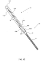
- FIG. 14-18 A second embodiment of a compression clip 510 constructed according to the present invention is shown in Figs. 14-18 , to which reference is now made.
- Figs. 14 and 15 show clip 510 in its closed and open position, respectively.
- Fig. 16 is an exploded view of the clip and discussion of the clip will be made in conjunction with that Figure.
- Most of the elements in Figs. 14-18 are the same as those discussed in conjunction with the clip embodiments shown in Figs. 2-3B .
- Elements that are essentially equivalent in structure and operation will not be discussed again. Only new elements or structural features will be described. Essentially identical or equivalent elements in the embodiments have been numbered as in clips 10 with the addition of 500 as a prefix.
- hinge springs 512A and 512B are not symmetrical, each having legs which are of different lengths.
- Legs 508A and 508B are longer than legs 509A and 509B.
- Bi-directional connectors 517 are formed at the end of legs 509A and 509B. These connectors formed substantially transversally to the body of clip 510 are sized and configured to be inserted into holes 521 on securing element 514A and holes 519 on compressing element 516A.
- At the end of legs 508A and 508B are hollow cylinders 532A and 532B insertable over projections 530, more fully described below.
- compressing element 516A is configured essentially as in Figs. 2-3B
- compressing element 516B is a hollow tubular rod with two slots 538 on its surface proximal to securing element 514B.
- a rod, formed of two connected threaded bolts 536A and 536B is positioned inside compressing element 516B.
- the length of each threaded bolt is less than half the length of the rod, with the bolts separated by connector means 540.
- Threaded bolts 536A and 536B each have different "handedness", that is thread direction. Because the two threaded bolts have different "handedness" they separate when turned in one direction and come closer together when turned in the opposite direction.
- Threaded bolts 536A and 536B Over the ends of threaded bolts 536A and 536B are fitted cylindrical elements 528, the latter having complementary threads on their inner surface. Threaded bolts 536A and 536B have an attachment means 534A and 534B on their ends for insertion and joining with cylindrical elements 528. Cylindrical elements 528 are each formed with a projection 530 protruding substantially transversally to the long axis of cylindrical elements 528. Projections 530 pass through slots 538 preventing fitted cylindrical elements 528 from turning as threaded bolts 536A and 536B are turned. This forces cylinders 528 to move linearly along the long axis of compression element 516B. The threaded rod with cylinders 528 are held to compressing element 516B by plugs 526.
- Projections 530 on cylindrical elements 528 are configured and sized to be inserted into hollow cylinders 532A and 532B formed on the longer legs 508A and 508B of springs 512A and 512B.
- the placement of legs 508A and 508B of hinge springs 512A and 512B and the relationship between plugs 526, cylindrical elements 528 and threaded bolts 536A and 536B (which when joined form the threaded rod discussed above) are best seen in Figs. 17 and 18 .
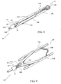
- FIGs. 19-23 show a clip applier 550 that can be used to operate clip 510, the latter described in conjunction with Figs. 14-18 .
- Figs. 19 and 20 show clip applier 550 in its engaged and disengaged position, respectively, with clip 510.
- a cable 552 capable of being rotated is extended through a tube 554, typically a flexible plastic tube capable of advancing the clip to the distal end of an endoscope. Cable 552 ends at rotation head 558 which includes a washer element 560 and a male element 562, the latter sized and configured for insertion into recess 524 of clip 510 ( Figs. 14-18 ).
- tube 554 may be a spring having sufficient flexibility to advance a clip attached to applier 550 past the distal end of the endoscope.
- Clip 510 for example, is inserted into a cup 556 of clip applier 550.
- Cup 556 typically is made of plastic or metal.
- Plug 526 with recess 524 ( Figs. 14-18 ) is positioned proximate to applier 550.
- Male element 562 is inserted into recess 524 of clip 510.
- Recess 524 and male element 562 are configured to be mateable.
- Moving clip 510 forward or backward is effected by pushing or pulling cable 552.
- Rotating cable 552 opens and closes the clip depending on the direction of rotation and the sequence of the bolts and the "handedness" of the threaded bolt proximate to male element 562.
- Pushing forward releases clip 510 from applier 550.
- washer element 560 pushes clip 510 out of cup 556.
- male element 562 is released from recess 524 of clip 510, thereby fully releasing the clip from the applier.
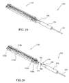
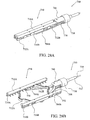
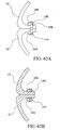
- FIG. 24A and 24B A third embodiment of a compression clip constructed according to the present invention is shown in Figs. 24A and 24B , to which reference is now made.
- FIG. 24A which shows an exploded view of clip 610, it is readily apparent that many of the elements presented there have been encountered and described previously in conjunction with previously discussed embodiments of compression clips constructed according to the present invention. Accordingly, elements that are structurally and operationally similar to previously described elements will not be described again here. Essentially identical or equivalent elements to those found in clips 10 and 510 have been numbered as in clips 10 and 510 with the prefix 600.
- Securing and compressing elements 614A, 614B and 616A, 616B, respectively, are essentially the same as in clip 510.
- Hinge springs 612A and 612B are unsymmetrical as in clip 510.
- Compressing element 616B is again a hollow tubular member with two slots 638.
- the longer legs 608A and 608B of hinge springs 612A and 612B include unidirectional connectors 624 at their ends which extend in the direction of compressing element 616B allowing for insertion into preformed holes 630 of cylindrical elements 628, to be discussed below.
- Cylindrical elements 628 are insertable into and retained in hollow tubular compressing element 616B. Holes 630 of cylindrical elements 628 act as receiving recesses for connectors 624 of springs 612A and 612B. When connectors 624 are inserted into holes 630 they are movable in slots 638 and do so with the opening and closing of springs 612A and 612B. Tubular compressing element 616B is capped by plugs 626. The plug 626 distal to the user has a hole into which pin 634 is inserted.
- wires 639A and 639B Passing through tubular compressing member 616B are wires 639A and 639B. These wires have loops 640A and 640B at their ends configured to fit over connectors 624.
- FIG. 24B Upon viewing Fig. 24B , the arrangement of the various elements of clip 610 and their operation becomes evident.
- clip 610 has been flipped vis-a-vis the view shown in Fig. 24A and compressing element 616B and securing element 614B are not presented.
- legs 608A and 608B of springs 612A and 612B separate as do securing elements 614A and 614B (the latter not shown) and compressing elements 616A and 616B (the latter not shown).
- wire 639B passes around pin 634 when pulled.
- FIG. 25A-26B A fourth embodiment of a surgical compression clip constructed according to the present invention is shown in Figs. 25A-26B , to which reference is now made.
- the present embodiment is different from the embodiment of Figs. 2-3B in that the bi-directional hinge spring connectors 717 are now joined on the inside of hinge spring arms 708 of spring elements 712A and 712B (best seen in Fig. 4C ) and not at the ends of hinge spring arms 8 of hinge spring elements 12A and 12B as in Figs. 2-3B and Figs. 4A and 4B . Additionally, and as a direct result of the new positioning of hinge spring connectors 717, spaces 725 must be formed in lateral walls 727 of securing elements 714A and 714B. These spaces are absent in walls 27 of securing elements 14A and 14B as seen and labeled in Fig. 3B . Its necessity with the present clip embodiment is readily seen in Figs.
- securing elements 714A and 714B may be a single integral structure or elements made from several parts joined together by any process known to those skilled in the art, such as by welding. This is true as well for the securing elements shown in previous embodiments and discussed elsewhere herein.
- connectors 717 on the inside of arms 708 of hinge spring elements 712A and 712B effectively creates a preload that allows the clip to open wider while still applying the forces needed for the necrotic process.
- An alternative, or additional, technique to achieve preloading is to heat hinge spring elements 712A and 712B and shape them during manufacture.
- hinge spring elements 712A and 712B exert a force on compressing elements 716A and 716B even when clip 710 is in its closed position.
- Clip 710 is effectively preloaded and a gap 711 (best seen in Fig. 25B ) exists between securing elements 714A and 714B even when clip 710 is in its closed position.
- This gap typically, but without intending to be limiting, is in the range of 0.7 to 0.9 mm, which ensures that the force exerted by clip 710 falls to zero before it has a chance to cut through the healing tissue. It should be remembered that when the necrotic process is in an advanced stage, tissue thickness is reduced significantly
- Gap 711 can be formed in one of many ways. Without intending to be limiting, one of these ways is by forming gap forming projections 713 (best seen in Figs. 25B , 26A and 26B ) at the end of one or both ends of compressing elements 716A and 716B.
- FIG. 27A-28B An embodiment of a clip applier 750 that can be used with clip 710 of Figs. 25A-26B is shown in Figs. 27A-28B . While discussed in terms of its use with the clip shown in Figs. 25A-26B , it should readily be understood that applier 750, with little or no modification, may be used with other clip embodiments discussed above.
- Figs. 27A and 27B are isometric views of clip applier 750, the applier shown in its closed and open position, respectively.
- Figs. 27C and 27D are cross-sectional views of the applier in Figs. 27A and 27B , respectively.
- Figs. 28A and 28B are isometric views of the clip applier shown in Figs. 27A-27B in its closed and open position, respectively, when attached to and operating the clip shown in Figs. 25A-26B .
- Figs. 27A-27D shows a wire or cable 754 encased in a sheath 752 which extends toward, and exits from, the body cavity so that it can be operated by a user.
- Wire (or cable) 754 is attached to a cam 756 which is positioned inside applier body 760, the later covered by applier body cover 758.
- Applier body 760 at its distal end includes a hole 762 on each of two opposing walls.
- Applier 750 includes two arms 764A and 764B each having a projection 768 at their proximal end and attachment projections 770 at their distal end. Attachment projections 770 attach to clip 710 ( Fig.
- Arms 764A and 764B each have an aperture (not shown) to receive a pin 766 ( Figs. 27C and 27D ) which also passes through holes 762 of applier body 760.
- Pin 766 serves as an axis around which arms 764A and 764B rotate.
- Arms 764A and 764B each have a bend 772 in them which allows the positioning of projections 768 on arms 774 of cam 756.
- applier 750 is shown in its closed position.
- Wire or cable 754 has been pushed in the distal direction, i.e. away from the user, causing attached cam 756 to also move in the distal direction within applier body 760.
- Space 759 is formed between cam arms 774 and cam flanges 757. This results in applier arms 764A and 764B moving to a position where they are adjacent to each other.
- clip 710 is brought to its closed position as best seen in Fig. 28A .
- applier 750 is shown in its open position.
- Wire 754 has been pulled in the proximal direction, i.e. toward the user, causing attached cam 756 to also move in the proximal direction in applier body 760.
- clip 710 is brought to its open position as best seen in Fig. 28B .
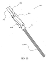
- Figs. 29 through Fig. 30C show various views of another embodiment of a clip applier 800 which may be used with many of the surgical clips discussed herein.
- Fig. 29 is an exploded view of clip applier 800.
- Figs. 30A and 30B are isometric views of clip applier 800 shown in Fig. 29 in its closed and open position, respectively.
- Fig. 30C is an inner, totally cut-away view of Fig. 30B .
- a wire or cable 812 with a threaded end 814.
- Wire or cable 812 extends to and exits from the body cavity so that it can be operated by a user.
- Threaded end 814 of wire or cable 812 is inserted into jagged entry 820 of applier body 818.
- a casing (not shown) of wire or cable 812 is caught on the jagged surface of entry 820.
- the threaded end 814 of wire or cable 812 is threaded into a threaded bolt 822 of configuration controller 816 when controller 816 is positioned in guide slot 826A (discussed below) of applier body 818.
- Configuration controller 816 is formed to also include two wing elements 824 and a projection 830.
- Applier body 818 includes a first and a second guide slot 826A and 826B, respectively, and configuration controller 816 is positioned so that it rides in first guide slot 826A. Wing elements 824 of configuration controller 816 move freely in first guide slot 826A. Proximal ends 828 of applier arms 802A and 802B are positioned in and move in second guide slot 826B.
- Applier arms 802A and 802B each include an attachment projection 804, a hole 806 and an arm guide slot 808.
- Projection 804 connects to the surgical clips in a manner similar to that shown elsewhere herein.
- a pin 810 is inserted through hole 829 of applier body 818 and through holes 806 in applier arms 802A and 802B. This pin acts as an axis of rotation when arms 802A and 802B are brought proximate to or spaced apart from each other.
- projection 830 of configuration controller 816 passes through arm guide slots 808 of applier arms 802A and 802B.
- configuration controller 816 advances in the distal direction of guide slot 826A with projection 830 ( Fig. 29 ) moving towards the distal end of arm slots 808 ( Fig. 29 ). This causes applier arms 802A and 802B to rotate towards each other and attain their closed position.
- configuration controller 816 moves in the proximal direction in guide slot 826A and projection 830 moves towards the proximal end of arm slots 808 causing applier arms 802A and 802B to rotate away from each other and attain their open position ( Figs. 30B and 30C ) .
- Wing elements 824 of configuration controller 816 prevent turning of controller 816 when rotated by the threaded end 814 ( Fig. 29 ) of wire/cable 812, thereby allowing for the conversion of rotational motion into translational motion.
- clip appliers can be designed as the surgical procedure and nature of the tissue to be closed warrants. The design would generally require little or no modification to the applier shown in these Figures, and those shown in concurrently filed pending application "Endoscopic Full Thickness Resection Using Surgical Compression Clips" owned by the same Applicant, incorporated by reference herein in its entirety.
- Fig. 45 shows an endoscope insertion shaft 300 with a working channel 154. It also contains several auxiliary elements, here three, denoted as 157A-157C. The number of working and auxiliary channels may be more or less in other embodiments of shaft 300.
- a multi-lumen plastic sleeve 150 is brought to and over endoscope insertion shaft 300 ( Fig. 46 ).
- the endoscope insertion shaft 300 is encased in the primary lumen 155 of the multi-lumen sleeve 150 and the one or more secondary lumens 158 of sleeve 150 are typically collapsed and, if needed, held by bands 160 ( Fig. 47A ).
- the bands 160 are expandable when working instruments are inserted into the collapsed secondary lumens 158. Insertion of these instruments occurs after the distal end 152 of the endoscope shaft 300 is positioned proximate to the suspect lesion. Bands may not be required in some embodiments, if the secondary lumens 158 remain collapsed by themselves while the encased endoscope insertion shaft 300 ( Fig. 47A ) is inserted into a body organ or if not required by the physician. It is to be understood that means or methods other than bands may be used to ensure that the secondary lumens remain collapsed while the encased endoscope shaft is inserted into the body and positioned near the suspect lesion.
- the encased endoscope insertion shaft 300 is advanced within the body lumen until it is near the lesion, herein taken to be a polyp P in the gastrointestinal (GI) tract. ( Fig. 48 ).
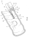
- Clip 10 still in its closed position, is brought to its final position adjacent to polyp P ( Fig. 50 ).
- a grasper assembly is then inserted into a working channel 154 of the endoscope insertion shaft 300, advanced through the shaft, and then advanced out of the distal end 152 of endoscope insertion shaft 300 to the region adjacent to polyp P ( Fig. 51 ).
- the grasper assembly i.e. grasper (not shown) and grasper transporting element 260, is introduced via a secondary lumen 158 of the multi-lumen sleeve 150 and not through a working channel 154 of the endoscope shaft. From an operational point of view, this has no significant effect on the method described.
- the grasper assembly, clip 10 and clip applier 30 may be advanced through the same secondary lumen 158 from the proximal end of the endoscope shaft to the suspect lesion.
- the grasper assembly may be inserted into and advanced through a second working channel of the endoscopic insertion shaft.
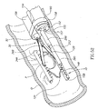
- Clip 10 is then opened by applier 30.
- the opened clip is positioned so as to bound polyp P so that the lesion can be pulled through the clip.
- Fig. 52 shows an isometric view of this step.
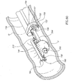
- the grasper (not shown) remains inside its grasper transporting element 260. Now the forceps arms 252 of the grasper are ejected from grasper transporting element 260 and positioned to grasp polyp P through the open clip ( Figs. 53 and 54 ).
- Polyp P is then pulled by forceps arms 252 into the separated compressing and securing elements 16A, 16B and 14A, 14B, respectively, of open clip 10. This is shown in a top side view in Fig. 55 . In this view, one of the forceps arms 252 of the grasper is barely visible; most of this arm and the entire second forceps arm are obscured by polyp P.
- the polyp is rotated over and wrapped around grasper transporting element 260.
- This rotation is shown in an isometric view in Fig. 56 and a cross section view ( Fig. 57 ) along line AA' of Fig. 56 .
- Rotation is effected by the rotation of the entire grasper assembly, the grasper with forceps arms 252 holding the pulled polyp P, the grasper transporting element 260 and the assembly's shaft (not shown) using a control handle positioned outside the body cavity.
- rotating the control handle outside the body can be avoided by creating a swivel mechanism in the mechanical connection with the grasper assembly and rotating the swivel mechanism. Rotation ensures that sufficient tissue is being maneuvered into clip 10 and near severing device 310 (shown in Fig. 60 ) to allow for full transmural resection.
- Clip applier 30 then closes clip 10 around the pulled and rotated polyp P ( Fig. 58 ).
- Clip applier 30 is detached from the closed clip 10 and withdrawn via the secondary lumen 158 through which it entered ( Fig. 59 ).
- clip applier 30 could be detached from clip 10 after tissue resection.
- Polyp P wrapped around grasper transporting element 260 and compressed by clip 10 is severed by a severing device 310 shown being positioned close to polyp P ( Fig. 60 ).
- Severing device 310 may be advanced to the polyp through the endoscope's working channel 154 or through a secondary lumen 158 of sleeve 150.
- severing device 310 has been advanced to its position for severing through the secondary lumen 158 used for advancing clip 10 and its applier 30.
- Severing device 310 approaches polyp P and severs it from the wall of the GI tract. The actual step of severing is not shown.
- the closed surgical compression clip 10 remains around that portion of the GI wall from which the tissue was resected ( Figs. 61 , 62A and 62B ). Compression continues until necrosis is induced and healing of the resected site occurs. Clip 10 is naturally expelled from the body through the rectum or retrieved by the physician if needed.
- step of pulling the polyp with a grasper is optional since in most situations wire 90 loop by itself can be maneuvered to encompass, grasp and pull the polyp or its stalk.
- insertion of closed clip 70 is effected through a secondary lumen of a multi lumen sleeve, but it also may be advanced through a working channel of the endoscope.
- the step of applying applier 105 occurs only after clip 70 has exited the secondary lumen or working channel.
- the invention has been described as being used in bowel polyp resections. It should be evident to one skilled in the art that other types of lesions, in other organs in other organ systems, can also be resected using the present invention with little or no modification.
- organs include, but are not limited to, the urinary bladder and other organs of the urinary tract, the uterus, the liver, the esophagus, the gall bladder, the lungs and the rectum.
- system and method of the present invention have been described as being used in endoscopic procedures which do not require a direct incision into the body cavity.
- the system and method as described herein above has been described as being inserted into the body cavity through one of the body's existing orifices.
- the system and method described herein above can be used in open surgical procedures with little or no modification, where the point of entry of the system is an incision into the body cavity.
- the device and method of the present invention can be used to excise animal tissue as well as human tissue, particularly, but without being limiting, tissue of other mammalian species.
Abstract
Description
- The present invention relates to the field of surgical compression clips generally, and, in particular, to the field of surgical compression clips, at least partially formed from shape memory material.
- Several methods are known in the art for joining tissue portions at the site of organ resections, particularly gastrointestinal (GI) tract resections, or at the site of other types of tissue perforations or tissue openings. These include threads for manual suturing, staplers for mechanical suturing, tissue adhesives and compression rings and clips.
- While manual suturing is universally known and relatively inexpensive, the degree of success depends considerably on the skill of the surgeon. Another disadvantage of this technique is that post-operative complications are common. Further, suturing an organ results in lack of smoothness of the tissue therein, which, when the sutured organ is part of the gastrointestinal tract, hampers peristalsis in the sutured area. Finally, suturing is both labor and time consuming.
- Increasingly, stapling is being used for suturing. Staplers for mechanical suturing ensure a reliable joining of tissue and reduce the time needed for surgery compared with manual suturing. However, after healing, metal staples remain in place along the perimeter of the suture, which reduces elasticity of the junction and adversely affects peristalsis when the sutured organ is part of the gastrointestinal tract. These complications often lead to strictures and inflammatory reactions to the foreign bodies left behind. Staples also often lead to undesired leakage of blood and other body liquids into the region of resected tissue further resulting in severe infection. Additionally, stapling mechanisms generally are relatively large and fairly rigid, limiting the maneuverability of an endoscope used in conjunction with the stapling mechanism. This lack of maneuverability restricts an endoscopic approach to many locations within the body.
- Junctions using compression devices, such as rings (or loops) and clips, ensure the best seal and post-operative functioning of the organs. The compression force exerted by compression rings is applied only momentarily at the tissue junction and is reduced as the tissue is crushed. Clips made of memory alloys enable portions of tissue to be pressed together with increasing pressure as they are heated, due to the inherent properties of the alloys. Their design is cheap and they are small in size. Moreover, when used in the GI tract they are often self-evacuated.
- A major disadvantage of known clips is that they permit compression of only approximately 80-85% of the junction perimeter, thus requiring additional manual sutures, which reduce the integrity of the seal of the junction during the healing period and its elasticity during the post-operative period. Furthermore, this additional suturing is problematic inasmuch as it has to be carried out across a joint which includes a portion of the clip, thereby rendering difficult the sealing and anastomosis of the organ portions.
- The compressive force exerted by clips generally is not equal at both ends of the clip because of the clips' typically asymmetric construction. Similarly, compression does not act along a line between the two compressing portions holding the tissue to be compressed. This can lead to the clip disengaging from the closure site before closure is complete and scar tissue mature.
- Typically, clips do not necessarily have a securing mechanism against slipping off the tissue. Clips as currently designed may also affect the maneuverability of an endoscope.
- A typical surgical clip is described in
WO 2004/080314 to Wild . The clip is designed for occluding a vein artery or other body passages, occlusion not including piercing or cutting the body part. The surgical clip for occluding a body passageway comprises a base portion, a pair of resilient limbs configured to extend generally laterally outwardly from the base portion and each having a free end disposed forward of the base portion, and a reaction portion mounted to the base portion. The reaction portion defines a generally forwardly directed reaction surface disposed between the base portion and the free ends of the limbs. The limbs are movable under a resilient restoring force from a first, open, condition, in which a gap is provided between the limbs and the reaction portion for receiving the body passageway into the clip, to a second, closed, condition, in which the limbs cooperate with the reaction portion to grip the body a passageway and to occlude it. The clip may be formed from NitinoL When the clip is in use, the base portion twists and forms a plane that is at an angle with the limbs of the clip. - A surgical suturing clamp is taught in
US Publ App 2003/0093091 to Paolitti . The clamp provides an improved surgical loop for constricting or ligating, partially or fully, an anatomic conduit during a surgical intervention. The surgical loop is preferably comprised of an elastomeric tubular body, a curved needle that is attached to one free end of said tubular body to facilitate its insertion through a body tissue containing an anatomic conduit and a pledget which is frictionally engaged and positionable along the length of said tubular body. The pledget is frictionally engaged with a first portion of tubular body through a closed-perimeter opening, thereby forming an integral assembly with said tubular body A second portion of tubular body is subsequently frictionally engaged or restrained with pledget through a slot configured therein. The pledget is preferably configured with a bias means which maintains said slot in a biased-closed configuration, thereby frictionally engaging and restraining said second portion of tubular body. It should be noted that the linear compression elements in Paolitto compress a flexible elastomeric tubing and not tissue. - "Proximal" relates to the side of a clip or device closest to the user, while "distal" refers to the side of a clip or device furthest from the user.
- "Lesion" may be used in place of the word "polyp" "perforation", hemorrhoid, tissue adjacent to a resected site, or openings within tissue generated by any surgical procedures, without any intent at differentiating these different types of lesions, except where specifically indicated.
- "Gastrointestinal tract" or its equivalents are used in the specifications and claims without intent of being limiting. Other organ systems, and lesions found therein, are also contemplated as being treatable with the compression clips and devices described in the present specification.
- "Hinge spring" is one type of a "force applier" and this latter term may be used herein interchangeably with hinge spring without any intent at differentiating between these terms, except where specifically indicated. Accordingly, the latch described herein, as well as elements having other shapes, may also be considered to be force appliers if they are used for, and their operation is based on, their being formed from and possessing the force applying properties of shape memory materials. Hinge springs may be described herein as "hinge members", "force means" and "hinge members" again without any attempt at differentiating between these terms except where specifically indicated.
- "Endoscope" as used herein should be construed as including all types of invasive instruments, flexible or rigid, having scope features. These include, but are not limited to, colonscopes, gastroscopes, laproscopes, and rectoscopes. Similarly, the use of "endoscopic" is to be construed as referring to all types of invasive scopes.
- The present invention seeks to provide an improved surgical compression clip having force appliers/force means formed of a shape memory alloy material. These clips may be used for joining tissue at the resection site in resections of many kinds, as well as for closing various other types of organ perforations. They may be used inter alia in polypectomies, gastrectomies and gastroplastic procedures.
- It is an object of the present invention to provide a surgical compression clip which exerts a constant compressive force irrespective of thickness of the compressed tissue, and irrespective of the changes it undergoes during the wound healing process. Such a clip reduces the chances of liquid leakage after resection while ensuring proper healing and closure of the resected site. Typically, but without intending to be limiting, no foreign body is left behind after tissue closure is complete.
- It is a further object of the present invention to provide a clip that ensures protection against the clip being expelled before tissue closure is complete.
- Another object of the present invention is to provide a non-unitary surgical clip which exerts a constant compressive force along the entire profile of the surfaces of the clip's clamping elements. The clip is made of shape memory material which provides a constant compressive force over large elongations.
- In yet another object of the present invention a surgical compression clip is provided that produces continuous clamping compression of tissue adjacent to a resected site. The continuous compression is effected along a continuous line, thereby preventing undesired post-surgery fluid leakage and bleeding. Such a continuous line is impossible to attain when using surgical staples.
- It is a further object of the present invention to provide a surgical compression clip and a system for applying the clip that reduces the risk of tissue perforation when all tissue layers proximate to a lesion are resected.
- The surgical clips described herein may find particular use in various types of resections of a suspect lesion, such lesion arising in, for example, but without intending to be limiting, the bowel, rectum, appendix, gallbladder, uterus, stomach, esophagus, etc.
- The improved surgical clip assembly according to the invention comprises:
- a pair of generally linear compression elements for securing tissue therebetween and for applying to the secured tissue a compression force, each compression element having a first end portion and a second end portion, wherein said clip assembly has an initial, open position in which said linear compression elements may be positioned about tissue to be secured therebetween, and a final, closed position whereat said compression elements are substantially parallel to each other, thereby to apply a compressive force to the secured tissue; and
- a first and a second hinge member said first hinge member disposed between said first end portions of said pair of compression elements and said second hinge member disposed between said second end portions of said compression elements,
- wherein said first and second hinge members are in mechanical communication with said first and second end portions of said linear compression elements, respectively, and said hinge members are operative to transmit operational forces therebetween, and
- wherein said hinge members and compression elements form a closed bounded surface in both the open and closed positions of said clip.
- Such a surgical clip assembly manifests an advantageous combination of features not known in the art described above. In Wild (
WO 2004/080314 ), there is a first but no second hinge member and there are no linear compression elements as required by the invention. In view of the lack of a second hinge element, there can be no closed bounded surface as required by the invention. In Paolitti (2003/0093091 - In some embodiments of the present invention as described in
claim 1 and also described above, the hinge members are typically formed of a shape memory material. - In some embodiments of the clip assembly, the assembly further includes a pair of generally linear securing elements, wherein each of the linear compression elements is associated with one of the pair of generally linear securing elements. The securing elements are operative for securing tissue to be compressed by the compression elements and the securing elements and form a securing line when grasping the tissue. The securing line is not collinear with the line of compressive force produced by the compression elements. Typically, the securing elements include a gripping portion having a serrated profile formed of a plurality of teeth-like projections over at least part of the length of the securing elements. The teeth-like projections of the profile are not necessarily uniformly distributed along the length of the gripping portion although in some embodiments they may be. In some embodiments, the assembly further includes one or more receiving structures sized and configured to disengageably receive an attachment element of a clip applier. The clip applier exerts a force counter to the force exerted by the two hinge members and is operable for bringing the clip assembly from its closed position to its open position or vice versa:
- In some embodiments of the clip assembly, the pair of securing elements and the pair of compressing elements are formed from material selected from the group of materials consisting of: an insulative material and an insulative-coated metal material. In some embodiments, the compressing elements and securing elements are integrally formed with each other. In instances where these are not integrally formed, they may be joined by a method chosen from the group of methods consisting of: welding, gluing, a mechanical clip, fixating joint or a mechanical press.
- In some embodiments of the clip assembly, the first and second hinge members are disposed in proximity to the first and second end portions, respectively, of the linear compression elements. In some embodiments the clip assembly may further include a pair of generally linear securing elements, wherein each of the linear compression elements is associated with one of the pair of generally linear securing elements. The securing elements are operative for securing tissue to be compressed by the compression elements and the securing elements forming a securing line when grasping the tissue. The securing line is not collinear with the line of compressive force produced by the compression elements. In a further embodiment of the clip assembly of the present invention, the securing elements include a gripping portion having a serrated profile formed of a plurality of teeth-like projections over at least part of the length of the securing elements. In some embodiments, the compressing elements and securing elements are integrally formed with each other. In instances where they are not integrally formed, they may be joined by a method chosen from the group of methods consisting of: welding, gluing, a mechanical clip, fixating joint or a mechanical press.
- In some embodiments of the clip assembly of the present invention, the first and second hinge members each has a generally planar body that includes two legs each having an end portion. Each of the hinge members has located at each of its end portions a connector having a single insertable end portion. The connector is positioned substantially transversally to the planar body. The clip assembly further includes a pair of generally linear securing elements, wherein each of the linear compression elements is associated with one of the pair of generally linear securing elements. The single insertable end portion of the connectors is pivotably connected to the compression elements, allowing concurrent mechanical communication between the hinge members and the compression elements.
- In some embodiments of the clip assembly of the present invention, the first and second hinge members each has a generally planar body that includes two legs. Each leg has an end portion. Each of the hinge members has located at each of its end portions a connector having a single insertable end portion. The connector is positioned substantially transversally to the planar body. The clip assembly further includes a pair of generally linear securing elements, and each of the linear compression elements is associated with one of the pair of generally linear securing elements. The single insertable end portion of the connectors is pivotably connected to the securing elements, thereby allowing concurrent mechanical communication between the hinge members and the securing elements.
- In some embodiments of the clip assembly of the present invention, the first and second hinge members each has a generally planar body that includes two legs each having an end portion. Each of the hinge members has located at each of its end portions a connector having first and second insertable end portions. The connectors are positioned substantially transversally to the planar body. The clip assembly further includes a pair of generally linear securing elements. Each of the linear compression elements is associated with one of the pair of generally linear securing elements. The first end portions of the connectors of the hinge members is pivotably connected to the securing elements, allowing concurrent mechanical communication between the hinge members with the two securing elements. The second insertable end portions of the connectors are pivotably connected to the compressing elements, allowing concurrent mechanical communication between the first and second hinge members and the two compressing elements.
- In some embodiments of the clip assembly, the connectors of the first and second hinge members are joined to the legs of the hinge members on an inner surface of the legs. This produces a preloaded clip assembly when the connectors are pivotably connected to one or more of the compressing elements and one or more of the securing elements.
- In some embodiments, the clip assembly further includes one or more gap forming elements positioned on one or more end portions of one or more compression elements. The gap forming element creates a gap between the compression elements when the clip assembly is in its closed position.
- In some embodiments of the clip assembly of the present invention, the two legs of the first and second hinge members are each of the same length. In another embodiment of the present invention, the two hinge members are identical but the legs of the hinge members are of different lengths.
- In some embodiments of the clip assembly of the present invention, one of the compression elements has a hollow tubular structure with an elongated slot at each of its ends positioned on the side of the one of the compression elements proximate to the hinge members. A projection translationally rides in each of the slots and is pivotally connected to the hinge elements and the one compression element mentioned above. When the projections riding in the slots ride away from each other, the longer of the legs of each of the hinge members travel in opposite directions from each other. This causes the hinge members to bring the clip assembly to its open position. When the projections ride in the slots towards each other the longer of the legs of each of the hinge members travel toward each other causing each of the hinge members to bring the clip assembly to its closed position.
- In some embodiments of the clip assembly of the present invention, the clip assembly further includes two joined threaded bolts positioned inside the hollow compression element. Each of the bolts has a different handedness and each has a threaded cylinder with an extension fitted thereon. Each of the extensions is pivotably connected to one leg of a different one of the hinge members. The extensions are operable as the projections for riding along the elongated slot when the threaded bolts are rotated. When rotating the joined bolts in one direction, the projections, being in mechanical communication with the bolts, travel in the slots in a direction away from each other. This brings the clip assembly to its open position. When rotating the joined bolts in a second direction, the projections travel in the slots in a direction toward each other thereby bringing the clip assembly to its closed position.
- In some embodiments of the clip assembly of the present invention, each of the hinge members has a connector positioned near the end portion of one of its legs. The connector serves as the projection for insertion into and translationally riding in the slots. The clip assembly further includes wires connected to the connectors. When the wires are pulled in one direction the connectors travel in the slots in a direction away from each other thereby bringing the clip assembly to its open position. When the wires are released, the connectors travel in the slots in a direction toward each other, bringing the clip assembly to its closed position.
- In some embodiments of the clip assembly, the assembly further includes one or more receiving structures sized and configured to disengageably receive an attachment element of a clip applier. The clip applier exerts a force counter to the force exerted by the one or more hinge members and is operable for bring the clip assembly from its closed position to its open position or vice versa.
- The present invention will be more fully understood and its features and advantages will become apparent to those skilled in the art by reference to the ensuing description, taken in conjunction with the accompanying drawings, in which:
-
Fig. 1A is an overall isometric view of an endoscopic system constructed according to the present invention; -
Fig. 1B is an enlarged view of the distal end of the endoscopic system shown inFig. 1A ; -
Fig. 1C is an enlarged view of the proximal end of the endoscopic system shown inFig. 1A ; -
Fig. 2 shows an isometric view of the compression clip constructed according to a first embodiment in its closed position; -
Figs. 3A and 3B show isometric top and bottom views of the compression clip shown inFig. 2 in its open position; -
Figs. 4A, 4B and 4C show isometric views of different configurations of spring elements constructed according to various embodiments of the present invention; -
Fig. 5 is an isometric view of a clip applier constructed according to one embodiment of the present invention, the applier in its closed position; -
Fig. 6 is an isometric view of the clip applier inFig. 5 , the applier in its open position; -
Fig. 7 is an isometric view of the clip applier inFig. 5 without its base element, the applier in its open position; -
Fig. 8 is an isometric view of the clip applier ofFig. 5 used to position the clip inFig. 2 , the clip being attached to the applier and in its closed position; -
Fig. 9 is an isometric view of a clip applier used to position the clip inFig. 2 , the clip being attached to the applier and in its open position; -
Fig. 10 is an isometric view of a clip applier constructed according to a second embodiment of the present invention, the applier in its closed position; -
Fig. 11 is an isometric view of the clip applier inFig. 10 , the applier in its open position; -
Fig. 12 is an isometric view of the clip applier ofFig. 10 , attached to a clip constructed as inFig. 2 , the clip being attached to the applier and in its closed position; -
Fig. 13 is an isometric view of the clip applier ofFig. 10 , attached to a clip constructed as inFig. 2 , the clip being attached to the applier and in its open position; -
Figs. 14 and 15 show isometric views of a second embodiment of a surgical compression clip constructed according to the present invention, whereinFig. 14 and Fig. 15 show the clip in its closed and open positions, respectively; -
Fig. 16 shows an exploded view of the clip inFigs. 14 and 15 ; -
Figs. 17 and 18 show isometric partially cut-away views of the compression clip shown inFigs. 14 and 15 , respectively; -
Figs. 19 and 20 show isometric views of a clip applier used with the clip shown inFigs. 14-18 ,Fig. 19 showing the applier engaged to the clip andFig. 20 disengaged from the clip; -
Fig. 21 shows an isometric view of the applier inFigs. 19 and 20 ; -
Fig. 22 shows a partially exploded view of the applier inFigs. 19 and 20 ; -
Fig. 23 shows a cross-sectional view of the applier shown inFigs. 19 and 20 ; -
Fig. 24A shows an exploded view of a third embodiment of a compression clip constructed according to the present invention; -
Fig. 24B shows an isometric partially cut-away view of the clip shown inFig. 24A ; -
Figs. 25A and 25B are an isometric top and bottom view of a clip constructed according to a fourth embodiment of the present invention, the clip being in its closed position; -
Figs. 26A and 26B are an isometric top and bottom view of a clip constructed according to the embodiment ofFigs. 25A and 25B , the clip being in its open position; -
Figs. 27A and 27B are isometric views of a clip applier constructed according to another embodiment of the present invention, the applier shown in its closed and open position, respectively; -
Figs. 27C and27D are cross-sectional views of the clip applier shown inFigs. 27A and 27B , the applier shown in its closed and open position, respectively; -
Figs. 28A and 28B are isometric views of the clip applier shown inFigs. 27A and 27B constructed in its closed and open position, respectively, when attached to and operating the clip shown inFigs. 25A-26B ; -
Fig. 29 is an exploded view of another embodiment of a clip applier for use with the clips in the specification herein; -
Figs. 30A and 30B are isometric views of the clip applier shown inFig. 29 in its closed and open position, respectively; -
Fig. 30C is a revealed inner view ofFig. 30B ; - Figs. 31A- 44 have been deleted as referring to an embodiment not claimed herein
-
Fig. 45 shows an endoscope prior to insertion into a multi-lumen sleeve; -
Fig. 46 shows the endoscope ofFig. 45 being inserted into a multi-lumen sleeve; -
Fig. 47A shows the endoscope after insertion into the multi-lumen sleeve; -
Fig. 47B shows an enlarged view of the distal end of the endoscope inFig. 47A ; -
Fig. 48 shows the sleeve-encased endoscope as it approaches a polyp in the gastrointestinal tract; -
Fig. 49 shows a view of a surgical clip attached to an applier being advanced to the site of the polyp through a secondary lumen of the sleeve; -
Fig. 50 shows a top side view of the surgical clip attached to an applier being positioned proximate to the polyp; -
Fig. 51 shows a top side view of a surgical clip and applier positioned proximate to a polyp and a grasper assembly being positioned proximate to the polyp after advancing through a working channel of the endoscope; -
Fig. 52 shows a top side view of the opened clip proximate to the polyp; -
Fig. 53 shows a top view of the grasper of the grasper assembly beginning to pull the polyp through the opened clip shown inFig. 52 ; -
Fig. 54 shows a top side view of the grasper of the grasper assembly grasping the polyp; -
Fig. 55 shows a top side view of the grasper continuing to pull the polyp through the opened surgical clip; -
Fig. 56 shows a top side view of the grasper and grasper transporting element rotating and wrapping the pulled polyp around the grasper transporting element; -
Fig. 57 shows a cross-sectional view along line AA' ofFig. 56 of the grasper and grasper transporting element rotating and wrapping the pulled polyp around the grasper transporting element; -
Fig. 58 shows a top side view of the surgical clip closing around the wrapped polyp; -
Fig. 59 shows a top side view of the closed surgical clip and polyp without the applier that has been withdrawn through a secondary lumen from the region of the resected polyp; -
Fig. 60 shows a top side view of the closed surgical clip and polyp with a severing device approaching the rotated polyp for severing; -
Fig. 61 shows a top side view of the tissue held by the clip at the resection site; and -
Figs. 62A and 62B show two side views of the tissue held by the clip at the resection site. - Similar elements in the Figures are numbered with similar reference numerals.
- The present application should be read in conjunction with co-pending
US patent published application number US 2007 213585 . - The present invention describes non-unitary surgical compression clips, which lessen the likelihood of internal leakage of bodily fluids which often occurs when staple suturing is used. These clips, when used, also lessen the likelihood of bleeding and do not leave any permanent foreign body inside the body cavity after tissue closure and healing is complete.
- The non-unitary, i.e. compound, surgical compression clips described herein, typically have one or more elements, generally two or more elements, made of a shape memory material, such as a nickel-titanium (Ni-Ti) alloys. The clip includes two compressing elements connected operationally by at least one of the shape memory elements. Typically, the clip also includes securing elements with which to hold the tissue being compressed. Also typically, the compressing elements are linear as are the securing elements. When tissue to be joined is held between the two compressing elements, a constant compressive force acts between the two elements, these latter being connected at both of their ends by the shape memory elements. The constant force is a result of the well-documented long plateau region of the shape memory material's stress-strain hysteresis curve. In this plateau region, the force is constant irrespective of the extent of the deformation. This is a consequence of properties exhibited by shape memory materials. Additionally, stress-induced strain is recoverable in these materials; in the case of nitinol, 6-8% of the strain can be recovered.
- Discussions of the stress-strain curves of shape memory materials and its stress induced strain can be found in many publications. See for example "Shape Memory Materials", edited by K. Otsuka and C.M. Wayman, Cambridge University Press 1998, p. 62 and; H. Tobushi et al in "Deformation Behaviour of Ni-Ti Superelastic Alloy Subjected to Strain Variation" in SMST-94: The Proceeding of the International Conference on Shape Memory and Superelastic Technology, edited by A. Pelton, D. Hodson and T. Duerig, 1995, pp. 389-391.
- It should be noted that the line of compressive force produced by the compression elements of the clips of the present invention is not collinear with the line exerted by the securing elements on the tissue to be resected. These are two different lines of action, separated by a distance. Were they to be co-linear the healing of the tissue at the compression site may be compromised. Additionally the arrangement of non-colinearity allows for more homogeneous tissue compression by the compression elements. Any penetration of the teeth for securing the tissue is compensated for by the continuous compression line more proximate to the body cavity wall.
- The shape memory elements, which act as force appliers, are typically made of nickel-titanium (Ni-Ti) alloys but other shape memory materials may also be used. The other elements of the clip, i.e. the compressing elements and the securing elements (and possibly separate toothed elements for attachment to the securing elements when there is no integrally formed toothed edge on the securing elements) may also be made of a shape memory material such as a nitinol alloy, but that is not essential. Other metals or alloys, such as stainless steel or other titanium alloys, and even certain plastic materials may also be used. The compression clips described herein are typically attached to an applier and brought to tissue adjacent to a resection site, or to tissue adjacent to a perforation to be joined, or to any tissue having an opening requiring closure.
- It should be noted that the line of compressive force produced by the compression elements of the clips of the present invention is not collinear with the line exerted by the securing elements on the tissue to be resected and/or closed. These are two different lines of action, separated by a distance. Were they to be co-linear the clip could easily disengage before scar tissue matured at the compression site. Additionally, the non-collinear arrangement allows for more homogeneous tissue compression by the compression elements. Furthermore, any penetration of the teeth on the securing elements for securing the tissue is compensated for by the clip's continuous compression line being further away from the resected site or the opening to be closed.
- The surgical clips described herein may be used with standard commercially available endoscopes. Dedicated or specially designed endoscopes can be used but are not necessary.
- Additionally, using the compression clips of the present invention is not limited to any particular direction or shape of resection incision; both radial and longitudinal incisions are contemplated by the present invention.
- The surgical clips described herein have additional advantages. The compression force ensures continuous compression of the tissue at the resected site, independent of the variation in tissue thickness. No foreign bodies are left behind in the body cavity as the clip is typically self-evacuating. Finally, since the invention makes use of shape memory materials, the clip may be of relatively small dimensions and there is no need for large instruments, such as currently employed stapler firing mechanisms. This permits easier advance of the clip and its applier to a site requiring closure.
- Before explaining several embodiments of the invention in detail, it is to be understood that the invention is not limited in its application to the details of construction and the arrangement of the components set forth in the following description or illustrated in the drawings. The invention is capable of other embodiments or of being practiced or carried out in various ways. Also, it is to be understood that the phraseology and terminology employed herein is for the purpose of description and should not be regarded as limiting.
-
Figs. 1A -1C , to which reference is now made, show an overall view of an endoscopic system constructed according to the present invention, an enlarged view of the system's distal end F and an enlarged view of the system's proximal end N, respectively. -
Fig. 1A includes anendoscope insertion shaft 300 encased in amulti-lumen sleeve 150.
At the distal end F ofendoscope insertion shaft 300, working instruments constructed according to the present invention may exit. These instruments include asurgical clip 10 attached to anapplier 30 and agrasper assembly 200 including agrasper transporting element 260. These instruments are inserted into a workingchannel 154 ofendoscope insertion shaft 300 or one or moresecondary lumens 158 ofsleeve 150. Insertion of the instruments is effected at the proximal end N ofendoscope insertion shaft 300. They are advanced in the direction of, and ultimately exit at, or adjacent to, the distal end F ofendoscope insertion shaft 300.Actuators Endoscope insertion shaft 300 is typically connected to afiberoptic cable 304 which communicates images to avisual display 302. - Details of the instruments used, the multi-lumen sleeve and other specific aspects of the system of the present invention are further discussed below.
- Reference is now made to
Figs. 2-3B whereFig. 2 presents a view of a non-unitary compression clip constructed according to a first embodiment of the present invention. InFig. 2 the clip is shown in its closed position.Figs. 3A and 3B present a view of the compression clip shown inFig. 2 in its open position. -
Clip 10 is constructed of two shape memory hinge springs 12A and 12B, also herein often denoted as force appliers. Typically, but without intending to be limiting, the shape memory material is a Ni-Ti alloy. The operation of the clip relies on shape memory effects exhibited by these materials.Springs -
Clip 10 further includes two securingelements teeth 20 for grasping tissue. Each of securingelements Teeth 20 may be formed integrally withelements metal compressing elements elements elements - Securing
elements spacings 18 configured and sized to receive the pushing elements of a clip applier (not shown). Compressingelements Fig. 3B ) into which connectors 17 (also best seen inFig.3B ) of hinge springs 12A and 12B are insertable. Insertion of hinge springs 12A and 12B occurs prior to welding or otherwise joiningtoothed securing elements elements elements connectors 17 of hinge springs 12A and 12B from dropping out ofholes 19. Securingelements elements elements Fig. 2 . - The metal used for forming
securing elements elements teeth 20, if these latter are made from separate pieces and welded toelements - While in the above embodiment, securing
elements elements elements elements elements respective compressing elements elements elements - In other embodiments, securing
elements elements springs elements elements -
Clip 10 in its closed position appears as shown inFig. 2 . Hinge springs 12A and 12B exert no force when the clip is fully closed, i.e. when compressingelements elements elements elements clip 10 is to be opened, pushing elements of a clip applier (not shown) may be positioned and wedged betweenteeth 20 of securingelements indentation 18. The applier is activated to apply a force via its pushing elements (not shown). This force opposes the force exerted byhinge springs spreads securing elements elements Figs. 3A and 3B . - After tissue is brought to and positioned between the separated compressing
elements elements Fig. 2 ). Shape memory hinge springs 12A and 12B also relax and return to their original shape. The tissue positioned between the securing and compressing elements ofclip 10 prevents compressingelements elements clip 10. This, in turn, causes the applier to disengage fromclip 10. - While the shape memory elements used to effect opening or closing of
clip 10 are here described as hinge springs, these elements can more generally be classified as force appliers. Therefore, it should be understood that elements of any shape which can generate a force for either opening or closing a compression clip may be used and these elements can and will often be denoted herein as force appliers. - In other embodiments, pushing elements of a clip applier are inserted into special indentations in securing
elements element 718 inFigs. 25A and26A discussed below. In yet another embodiment, when pushingsecuring elements elements - Shape memory hinge springs 12A and 12B can have
distinctive connectors 17 at their ends as shown inFigs. 4A-4C . A hinge spring havinguni-directional connectors 17 is shown inFig 4A . However, the use of hinge springs with bi-directional connectors 17' as shown inFig. 4B is advantageous over theuni-directional connectors 17 shown inFig. 4A . The hinge spring's bi-directionality allows connectors 17' to be inserted simultaneously intoholes 21 in securingelements holes 19 in compressingelements clip 10. It also reduces the chance that hinge springs 12A and 12B will be displaced during operation of the clip and interfere with closure of the clip. The positioning of hinge springs 12A and 12B with connectors 17' can readily be seen inFigs. 2 ,3A and 3B whereclip 10, in its closed and open positions, is shown. Reference to the use of hinge springs with connectors of the type ofconnector 717 shown inFig. 4C will be made later in the text -
Connectors Figs 4A, 4B and 4C respectively form articulating joints when they are inserted into corresponding apertures or holes in compression elements and/or securing elements as described in the first through fourth compression clip embodiments described below. These connectors rotate or swing in their respective apertures and holes allowing for articulation. - It should be noted that as in
clip 10 ofFigs. 2-3B , in someembodiments teeth 20 do not necessarily extend the entire length of securingelement clip 10 inFigs. 2-3B ,teeth 20 need not be distributed uniformly along securingelements elements small bend 22 welded or otherwise joined to the sides. In some embodiments, bend 22 may be integrally formed as part ofelements clip 10 slipping off the compressed suspect tissue during resection. - In the compression clip embodiments shown in
Figs. 2-3B and as discussed elsewhere in this specification, the securing elements and their respective compressing elements have been described as separate elements. In their operational state within the clips, these are typically a single joined element reflecting a single part and may be thought of as such. In the joined part, the securing elements attach to and grip the tissue to be resected while the compressing elements act to press the parts of the resected site together even when they are formed as separate elements and are only later joined together to operate as a single part. - Reference is now made to
Figs. 5-9 where various views of a first embodiment of a clip applier are shown. The clip applier may be used withsurgical compression clip 10 shown in and described in conjunction withFigs. 2-3B . -
Fig. 5 showsclip applier 30 in its closed position.Clip applier 30 is comprised ofapplier arms applier base 32, andconnector elements clip applier 30 are typically constructed of stainless steel but they may also be constructed of other metals, such as, but not limited to, titanium, titanium alloys or reinforced plastics. - As best seen in
Fig. 6 whereclip applier 30 is shown in it open position, each ofapplier arms insertion projection Insertion projections applier arms teeth 20 of securingelements Fig. 2 , or intoindentations 718 ofclip 710 inFig. 25A , or alternatively into holes positioned in securingelements elements -
Fig. 7 showsopen clip applier 30 without itsapplier base 32. - As seen in
Figs. 5 and 6 ,applier base 32 has a generally barrel-like shape from which emerges a pair ofapplier base projections 31. Each of theseprojections 31 has anapplier base slot 45 and an applierbase projection hole 37. Each ofapplier arms applier arm slots Applier arm 34B is constructed with abend 35 in it so that the distal portions ofarm 34B andarm 34A can lie in the same plane. It also allowsinsertion projections - Each of
connector elements holes 41A- 41D (41C and 41D not visible), one at each end of each element. -
Applier arms applier base 32 by connectingpin 43 which passes through applier base projection holes 37 and applier arm holes (not shown).Pin 42 is inserted into holes (not shown) inconnector elements applier base slots 45 andapplier arm slots pin 42 moves it forcesapplier arm slots applier base slots 45 at the point of the pin, thus creating an opening and closing effect. - The proximal ends of
connector elements Fig. 1A ), for example, positioned outside the proximal end N (Fig. 1A ) of the endoscope. -
Fig. 8 and Fig. 9 show clip applier 30 of the present embodiment attached tosurgical compression clip 10 described inFigs. 2-3B in its closed and open position, respectively. - To
open clip applier 30, an operating cable (not visible) pullsconnector elements applier base slots 45 and the proximal ends ofapplier arm slots applier arms Fig. 9 . - To close
clip applier 30, the tension in the operating cable (not visible) is released. In doing so, the force that hingesprings applier arms elements applier arms connector elements applier base slots 45 and the distal ends ofapplier arm slots applier arms Fig. 8 . - When
applier arms Fig. 9 ,insertion projections clip applier 30 push against the spacings betweenteeth 20 of securingelements clip 10 shown inFig. 2 (orindentations 718 ofclip 710 shown in and discussed below in conjunction withFigs. 26A and 26B ) so that securingelements elements clip 10 move apart. Whenapplier arms Fig. 8 ,insertion projections clip applier 30 exert a reduced force on the spacings between theteeth 20 of securingelements clip 10 inFig. 2 (or onindentions 718 ofclip 710 shown in and discussed in conjunction withFigs. 26A and 26B ) so that securingelements elements clip 10 move together. The counter force exerted byhinge springs clip applier 30 in place. Once tension generated bysprings clip 10 closes on and compresses tissue,insertion projections applier 30 essentially fall away and disengage fromclip 10. -
Figs. 10-13 , to which reference is now made, show various views of a second embodiment of a clip applier constructed according to the present invention. The applier is intended for use with the surgical compression clip (slightly modified as discussed below) shown in and discussed in conjunction withFigs. 2-3B .Fig. 10 shows the clip applier in its closed position, whileFig. 11 shows the applier in its open position. - Turning to
Fig. 11 first,clip applier 50 includesinsertion links links central bar 66. An operating cable (not shown) is connected to the proximal end ofcentral bar 66 and inserted intospring 52. The latter connection can be achieved by welding or any other connecting method or means known to those skilled in the art. -
Insertion links cylindrical elements Figs. 12 and13 ,cylindrical elements Figs. 10 and11 ) are themselves insertable into the ends of compressingelements Figs. 2-3B . - Compressing
elements Figs. 2-3B , require a slight modification to be compatible withcylindrical elements clip applier 50. To be compatible, at least one of the ends ofelements cylindrical elements clip applier 50 can be inserted into them. - While in the embodiment shown in
Fig. 10 andFig. 11 ,cylindrical elements insertion links -
Figs. 10 and11 show assembledclip applier 50 in its closed and open positions, respectively.Figs. 12 and13 show clip applier 50 inserted into compressingelements surgical compression clip 10 when the clip is in its closed and open positions, respectively. - Moving from the open to the closed position of clip applier 50 (or vice versa), and therefore to the open or closed position of clip 10 (or vice versa), can be effected using an operating cable (not shown) joined to, or in other ways in direct communication with, central bar 66 (
Fig. 11 ). The cable passes throughspring 52 and out of the proximal end N (Fig. 1A ) of the endoscope where it is activated by a user employing an actuator (schematically shown aselement 306 ofFig. 1A ). The actuator may be any of several types known to those skilled in the art. -
Spring 52, in addition to protecting the cable (not shown), serves as a stop sleeve forelement 56 while pulling the cable thus enabling the separation ofinsertion links - To
open clip applier 50,central bar 66 is pulled by the operating cable (not shown) in the proximal direction. When that occurs,interconnect links insertion links Fig. 11 due to the moment exerted onlinks clip 10 as inFig. 12 ,clip 10 also opens as shown inFig. 13 because of the force exerted byinsertion links cylindrical elements elements - During insertion of
clip 10 into a body cavity, the clip is attached to clipapplier 50 and bothclip 10 andapplier 50 are advanced, in their closed positions, through a secondary lumen of a multi-lumen sleeve (or through a working channel of the endoscope shaft). A tension is maintained in the operating cable (not shown) in order to keepclip 10 attached to clipapplier 50 during the entire advance from the proximal end of the secondary lumen (or working channel) to its distal end. The tension in the cable or wire, acts against the force of hinge springs 12A and 12B ofclip 10. This creates a force betweencylindrical elements applier 50 and compressingelements clip 10 preventing detachment ofclip 10 fromapplier 50. This force is smaller than the force required to openclip applier 50 andclip 10 attached to it. - To close
clip applier 50, the tension in the wire/cable (not shown) passing throughspring 52 is released. The force of hinge springs 12A and 12B is passed through compressingelements insertion links links spring 52. When that occursinterconnect links insertion links Fig. 10 . When they move together withclip 10 attached as inFig. 12 , compressingelements Fig. 12 . - While completely releasing the tension in the pull wire allows for the applier to fully return to its original closed position, the tissue pulled and held within
clip 10 prevents the clip from following the applier and fully returning to its original closed position. When this occurs,cylindrical elements clip 10 since the hinge springs' 12A and 12B force is acting essentially on the tissue instead of on the applier. - A second embodiment of a
compression clip 510 constructed according to the present invention is shown inFigs. 14-18 , to which reference is now made.Figs. 14 and 15 show clip 510 in its closed and open position, respectively.Fig. 16 is an exploded view of the clip and discussion of the clip will be made in conjunction with that Figure. Most of the elements inFigs. 14-18 are the same as those discussed in conjunction with the clip embodiments shown inFigs. 2-3B . Elements that are essentially equivalent in structure and operation will not be discussed again. Only new elements or structural features will be described. Essentially identical or equivalent elements in the embodiments have been numbered as inclips 10 with the addition of 500 as a prefix. - In
clip 510, hinge springs 512A and 512B are not symmetrical, each having legs which are of different lengths.Legs legs Bi-directional connectors 517 are formed at the end oflegs clip 510 are sized and configured to be inserted intoholes 521 on securingelement 514A and holes 519 on compressingelement 516A. At the end oflegs hollow cylinders projections 530, more fully described below. - While compressing
element 516A is configured essentially as inFigs. 2-3B , compressingelement 516B is a hollow tubular rod with twoslots 538 on its surface proximal to securingelement 514B. Inside compressingelement 516B, a rod, formed of two connected threadedbolts bolts - Over the ends of threaded
bolts cylindrical elements 528, the latter having complementary threads on their inner surface. Threadedbolts cylindrical elements 528.Cylindrical elements 528 are each formed with aprojection 530 protruding substantially transversally to the long axis ofcylindrical elements 528.Projections 530 pass throughslots 538 preventing fittedcylindrical elements 528 from turning as threadedbolts cylinders 528 to move linearly along the long axis ofcompression element 516B. The threaded rod withcylinders 528 are held to compressingelement 516B byplugs 526. Plug 526 on one side of the rod, the proximal side, includes arecess 524, typically, but without being limiting, a square recess, which is configured to receive a screw rotation apparatus (not shown).Projections 530 oncylindrical elements 528 are configured and sized to be inserted intohollow cylinders longer legs springs legs plugs 526,cylindrical elements 528 and threadedbolts Figs. 17 and 18 . - Reference is now made to
Figs. 19-23 which show aclip applier 550 that can be used to operateclip 510, the latter described in conjunction withFigs. 14-18 .Figs. 19 and 20 show clip applier 550 in its engaged and disengaged position, respectively, withclip 510. - The structure and operation of
clip applier 550 can best be understood by viewingFigs. 21-23 . Acable 552 capable of being rotated is extended through atube 554, typically a flexible plastic tube capable of advancing the clip to the distal end of an endoscope.Cable 552 ends atrotation head 558 which includes awasher element 560 and amale element 562, the latter sized and configured for insertion intorecess 524 of clip 510 (Figs. 14-18 ). - In some embodiments,
tube 554 may be a spring having sufficient flexibility to advance a clip attached to applier 550 past the distal end of the endoscope. -
Clip 510, for example, is inserted into acup 556 ofclip applier 550.Cup 556 typically is made of plastic or metal. Plug 526 with recess 524 (Figs. 14-18 ) is positioned proximate toapplier 550.Male element 562 is inserted intorecess 524 ofclip 510.Recess 524 andmale element 562 are configured to be mateable. Movingclip 510 forward or backward is effected by pushing or pullingcable 552. Rotatingcable 552 opens and closes the clip depending on the direction of rotation and the sequence of the bolts and the "handedness" of the threaded bolt proximate tomale element 562. - Pushing forward releases
clip 510 fromapplier 550. First,washer element 560 pushesclip 510 out ofcup 556. Then, by pullingcable 552 towards the proximal end of the endoscope,male element 562 is released fromrecess 524 ofclip 510, thereby fully releasing the clip from the applier. - A third embodiment of a compression clip constructed according to the present invention is shown in
Figs. 24A and24B , to which reference is now made. - From
Fig. 24A , which shows an exploded view ofclip 610, it is readily apparent that many of the elements presented there have been encountered and described previously in conjunction with previously discussed embodiments of compression clips constructed according to the present invention. Accordingly, elements that are structurally and operationally similar to previously described elements will not be described again here. Essentially identical or equivalent elements to those found inclips clips - Securing and compressing
elements clip 510. Hinge springs 612A and 612B are unsymmetrical as inclip 510. Again, there is abi-directional connector 617 on theshorter legs holes 621 in securingelement 614A and holes 619 on compressingelement 616A. Compressingelement 616B is again a hollow tubular member with twoslots 638. Thelonger legs unidirectional connectors 624 at their ends which extend in the direction of compressingelement 616B allowing for insertion into preformedholes 630 ofcylindrical elements 628, to be discussed below. -
Cylindrical elements 628, formed withholes 630, are insertable into and retained in hollowtubular compressing element 616B.Holes 630 ofcylindrical elements 628 act as receiving recesses forconnectors 624 ofsprings connectors 624 are inserted intoholes 630 they are movable inslots 638 and do so with the opening and closing ofsprings element 616B is capped byplugs 626. Theplug 626 distal to the user has a hole into whichpin 634 is inserted. - Passing through tubular compressing
member 616B arewires loops connectors 624. - Upon viewing
Fig. 24B , the arrangement of the various elements ofclip 610 and their operation becomes evident. InFig. 24B ,clip 610 has been flipped vis-a-vis the view shown inFig. 24A and compressingelement 616B and securingelement 614B are not presented. By pulling the ends E ofwires legs springs elements elements wire 639B, passes aroundpin 634 when pulled. Whenwires - After severance of the suspect tissue is effected, excess wire is cut and withdrawn from the endoscope and body.
- A fourth embodiment of a surgical compression clip constructed according to the present invention is shown in
Figs. 25A-26B , to which reference is now made. - This embodiment is very similar to the embodiment shown in
Figs. 2-3B and elements are numbered similarly with the inclusion of a prefix digit 7. Similar elements are constructed and operative as in the embodiment presented inFigs. 2-3B and, accordingly, will not be discussed again. - The present embodiment is different from the embodiment of
Figs. 2-3B in that the bi-directionalhinge spring connectors 717 are now joined on the inside ofhinge spring arms 708 ofspring elements Fig. 4C ) and not at the ends ofhinge spring arms 8 ofhinge spring elements Figs. 2-3B andFigs. 4A and 4B . Additionally, and as a direct result of the new positioning ofhinge spring connectors 717,spaces 725 must be formed inlateral walls 727 of securingelements walls 27 of securingelements Fig. 3B . Its necessity with the present clip embodiment is readily seen inFigs. 25A, 25B ,26A and 26B where hinge spring arms project, at least partially, throughspaces 725. It should be noted that securingelements - The positioning of
connectors 717 on the inside ofarms 708 ofhinge spring elements hinge spring elements - As best seen in
Figs. 25A and 25B , top and bottom views respectively ofclip 710, hingespring elements elements clip 710 is in its closed position. -
Clip 710 is effectively preloaded and a gap 711 (best seen inFig. 25B ) exists between securingelements clip 710 is in its closed position. This gap typically, but without intending to be limiting, is in the range of 0.7 to 0.9 mm, which ensures that the force exerted byclip 710 falls to zero before it has a chance to cut through the healing tissue. It should be remembered that when the necrotic process is in an advanced stage, tissue thickness is reduced significantly -
Gap 711, can be formed in one of many ways. Without intending to be limiting, one of these ways is by forming gap forming projections 713 (best seen inFigs. 25B ,26A and 26B ) at the end of one or both ends of compressingelements - An embodiment of a
clip applier 750 that can be used withclip 710 ofFigs. 25A-26B is shown inFigs. 27A-28B . While discussed in terms of its use with the clip shown inFigs. 25A-26B , it should readily be understood thatapplier 750, with little or no modification, may be used with other clip embodiments discussed above.Figs. 27A and 27B are isometric views ofclip applier 750, the applier shown in its closed and open position, respectively.Figs. 27C and27D are cross-sectional views of the applier inFigs. 27A and 27B , respectively.Figs. 28A and 28B are isometric views of the clip applier shown inFigs. 27A-27B in its closed and open position, respectively, when attached to and operating the clip shown inFigs. 25A-26B . -
Figs. 27A-27D , to which reference is now made, shows a wire orcable 754 encased in asheath 752 which extends toward, and exits from, the body cavity so that it can be operated by a user. Wire (or cable) 754 is attached to acam 756 which is positioned insideapplier body 760, the later covered byapplier body cover 758.Applier body 760 at its distal end includes ahole 762 on each of two opposing walls.Applier 750 includes twoarms projection 768 at their proximal end andattachment projections 770 at their distal end.Attachment projections 770 attach to clip 710 (Fig. 25A ) at its indentations 718 (Fig. 25A ).Arms Figs. 27C and27D ) which also passes throughholes 762 ofapplier body 760.Pin 766 serves as an axis around whicharms Arms bend 772 in them which allows the positioning ofprojections 768 onarms 774 ofcam 756. - Referring now to
Fig. 27C ,applier 750 is shown in its closed position. Wire orcable 754 has been pushed in the distal direction, i.e. away from the user, causing attachedcam 756 to also move in the distal direction withinapplier body 760. Due to the force applied byopen clip 710 onapplier arms projections 768 ofarms pin 766, towards the center and into thespace 759, best seen inFig. 27D .Space 759 is formed betweencam arms 774 andcam flanges 757. This results inapplier arms applier arms clip 710 is brought to its closed position as best seen inFig. 28A . - Referring now to
Fig. 27D ,applier 750 is shown in its open position.Wire 754 has been pulled in the proximal direction, i.e. toward the user, causing attachedcam 756 to also move in the proximal direction inapplier body 760. This forcesprojections 768 ofapplier arms applier arms projections 768 ofapplier arms cam arms 774. Whenarms clip 710 is brought to its open position as best seen inFig. 28B . -
Figs. 29 through Fig. 30C , to which reference is now made, show various views of another embodiment of aclip applier 800 which may be used with many of the surgical clips discussed herein.Fig. 29 is an exploded view ofclip applier 800.Figs. 30A and 30B are isometric views ofclip applier 800 shown inFig. 29 in its closed and open position, respectively.Fig. 30C is an inner, totally cut-away view ofFig. 30B . - In
Fig. 29 , there is a wire orcable 812 with a threadedend 814. Wire orcable 812 extends to and exits from the body cavity so that it can be operated by a user. Threadedend 814 of wire orcable 812 is inserted intojagged entry 820 ofapplier body 818. A casing (not shown) of wire orcable 812 is caught on the jagged surface ofentry 820. The threadedend 814 of wire orcable 812 is threaded into a threadedbolt 822 ofconfiguration controller 816 whencontroller 816 is positioned inguide slot 826A (discussed below) ofapplier body 818.Configuration controller 816 is formed to also include twowing elements 824 and aprojection 830. -
Applier body 818 includes a first and asecond guide slot configuration controller 816 is positioned so that it rides infirst guide slot 826A.Wing elements 824 ofconfiguration controller 816 move freely infirst guide slot 826A. Proximal ends 828 ofapplier arms second guide slot 826B. -
Applier arms attachment projection 804, ahole 806 and anarm guide slot 808.Projection 804 connects to the surgical clips in a manner similar to that shown elsewhere herein. When the proximal ends 828 ofapplier arms second guide slot 826B, apin 810 is inserted throughhole 829 ofapplier body 818 and throughholes 806 inapplier arms arms arms guide slot 826B,projection 830 ofconfiguration controller 816 passes througharm guide slots 808 ofapplier arms - Now referring additionally to
Figs. 30A and 30B , when wire orcable 812 is rotated in onedirection configuration controller 816 advances in the distal direction ofguide slot 826A with projection 830 (Fig. 29 ) moving towards the distal end of arm slots 808 (Fig. 29 ). This causesapplier arms cable 812 is rotated in the other direction,configuration controller 816 moves in the proximal direction inguide slot 826A andprojection 830 moves towards the proximal end ofarm slots 808 causingapplier arms Figs. 30B and30C ) .Wing elements 824 ofconfiguration controller 816 prevent turning ofcontroller 816 when rotated by the threaded end 814 (Fig. 29 ) of wire/cable 812, thereby allowing for the conversion of rotational motion into translational motion. - A method for effecting full transmural resection using the compression clips of the present invention is illustrated in
Figs. 45-62 to which reference is now made. - Operation of the clip in other situations where tissue closure is required is similar to its operation as shown in
Figs. 45-62 and discussion presented therewith. It should readily be understood by one skilled in the art, that clip appliers can be designed as the surgical procedure and nature of the tissue to be closed warrants. The design would generally require little or no modification to the applier shown in these Figures, and those shown in concurrently filed pending application "Endoscopic Full Thickness Resection Using Surgical Compression Clips" owned by the same Applicant, incorporated by reference herein in its entirety. - It should also be readily understood by one skilled in the art that certain features of the method and of the working instruments used as shown in
Figs. 45-62 would not be required in other tissue closure procedures. For example, a severing instrument may not always be required; similarly, a grasper assembly as used in the Figures may not always be needed. In some closure procedures commercially available instruments may be used. -
Fig. 45 , to which we now return, shows anendoscope insertion shaft 300 with a workingchannel 154. It also contains several auxiliary elements, here three, denoted as 157A-157C. The number of working and auxiliary channels may be more or less in other embodiments ofshaft 300. A multi-lumenplastic sleeve 150 is brought to and over endoscope insertion shaft 300 (Fig. 46 ). Theendoscope insertion shaft 300 is encased in theprimary lumen 155 of themulti-lumen sleeve 150 and the one or moresecondary lumens 158 ofsleeve 150 are typically collapsed and, if needed, held by bands 160 (Fig. 47A ). Thebands 160 are expandable when working instruments are inserted into the collapsedsecondary lumens 158. Insertion of these instruments occurs after thedistal end 152 of theendoscope shaft 300 is positioned proximate to the suspect lesion. Bands may not be required in some embodiments, if thesecondary lumens 158 remain collapsed by themselves while the encased endoscope insertion shaft 300 (Fig. 47A ) is inserted into a body organ or if not required by the physician. It is to be understood that means or methods other than bands may be used to ensure that the secondary lumens remain collapsed while the encased endoscope shaft is inserted into the body and positioned near the suspect lesion. - The encased
endoscope insertion shaft 300 is advanced within the body lumen until it is near the lesion, herein taken to be a polyp P in the gastrointestinal (GI) tract. (Fig. 48 ). - At that point a
surgical compression clip 10, and its attachedapplier 30, both in their closed positions, are advanced through asecondary lumen 158 of thesleeve 150 topolyp P. Clip 10 exits thesecondary lumen 158 still in its closed position (Fig. 49 ). -
Clip 10, still in its closed position, is brought to its final position adjacent to polyp P (Fig. 50 ). - A grasper assembly is then inserted into a working
channel 154 of theendoscope insertion shaft 300, advanced through the shaft, and then advanced out of thedistal end 152 ofendoscope insertion shaft 300 to the region adjacent to polyp P (Fig. 51 ). - In other embodiments, the grasper assembly, i.e. grasper (not shown) and
grasper transporting element 260, is introduced via asecondary lumen 158 of themulti-lumen sleeve 150 and not through a workingchannel 154 of the endoscope shaft. From an operational point of view, this has no significant effect on the method described. - In yet another embodiment, the grasper assembly,
clip 10 andclip applier 30 may be advanced through the samesecondary lumen 158 from the proximal end of the endoscope shaft to the suspect lesion. - In yet another embodiment, the grasper assembly may be inserted into and advanced through a second working channel of the endoscopic insertion shaft.
-
Clip 10 is then opened byapplier 30. The opened clip is positioned so as to bound polyp P so that the lesion can be pulled through the clip.Fig. 52 shows an isometric view of this step. - Up to this point, the grasper (not shown) remains inside its
grasper transporting element 260. Now theforceps arms 252 of the grasper are ejected fromgrasper transporting element 260 and positioned to grasp polyp P through the open clip (Figs. 53 and54 ). - Polyp P is then pulled by
forceps arms 252 into the separated compressing and securingelements open clip 10. This is shown in a top side view inFig. 55 . In this view, one of theforceps arms 252 of the grasper is barely visible; most of this arm and the entire second forceps arm are obscured by polyp P. - After, or simultaneously with, pulling polyp P, the polyp is rotated over and wrapped around
grasper transporting element 260. This rotation is shown in an isometric view inFig. 56 and a cross section view (Fig. 57 ) along line AA' ofFig. 56 . Rotation is effected by the rotation of the entire grasper assembly, the grasper withforceps arms 252 holding the pulled polyp P, thegrasper transporting element 260 and the assembly's shaft (not shown) using a control handle positioned outside the body cavity. Alternatively, rotating the control handle outside the body can be avoided by creating a swivel mechanism in the mechanical connection with the grasper assembly and rotating the swivel mechanism. Rotation ensures that sufficient tissue is being maneuvered intoclip 10 and near severing device 310 (shown inFig. 60 ) to allow for full transmural resection. -
Clip applier 30 then closesclip 10 around the pulled and rotated polyp P (Fig. 58 ).Clip applier 30 is detached from the closedclip 10 and withdrawn via thesecondary lumen 158 through which it entered (Fig. 59 ). Alternatively, if the physician feels it will assist him during the tissue resection,clip applier 30 could be detached fromclip 10 after tissue resection. - Polyp P wrapped around
grasper transporting element 260 and compressed byclip 10 is severed by asevering device 310 shown being positioned close to polyp P (Fig. 60 ).Severing device 310 may be advanced to the polyp through the endoscope's workingchannel 154 or through asecondary lumen 158 ofsleeve 150. InFig. 60 , severingdevice 310 has been advanced to its position for severing through thesecondary lumen 158 used for advancingclip 10 and itsapplier 30.Severing device 310 approaches polyp P and severs it from the wall of the GI tract. The actual step of severing is not shown. - After severance of polyp P, the severed polyp held by the forceps arms of the grasper, together with the remainder of the grasper assembly, the
severing device 310 and the endoscope shaft, are retracted in the direction of the proximal end of the endoscope and withdrawn from the body. Withdrawal directly from the body organ is a straight-forward step, and therefore this step of the method is not presented in a separate Figure. Polyp P can then be biopsied or treated as needed by a physician. - The closed
surgical compression clip 10 remains around that portion of the GI wall from which the tissue was resected (Figs. 61 ,62A and 62B ). Compression continues until necrosis is induced and healing of the resected site occurs.Clip 10 is naturally expelled from the body through the rectum or retrieved by the physician if needed. - The above step of pulling the polyp with a grasper is optional since in most situations wire 90 loop by itself can be maneuvered to encompass, grasp and pull the polyp or its stalk.
- Positioning the clip from the side as discussed above is a result of the polyp being encompassed by wire 90 when the latter is in its extended position. When made taut, the wire effectively pulls the polyp from a lateral position into the waiting open arms 72 and 74 of clip 70.
- Generally, insertion of closed clip 70 is effected through a secondary lumen of a multi lumen sleeve, but it also may be advanced through a working channel of the endoscope. The step of applying applier 105 occurs only after clip 70 has exited the secondary lumen or working channel.
- It is readily understood by one skilled in the art that a full thickness resection with wide lateral areas (margins) is very difficult to achieve using conventional surgical approaches and employing conventional surgical instruments. This is particularly true of large polyps and especially large sessile polyps. Grasping and pulling a large section of a, generally slippery, polyp is very difficult especially given the limited space available in the body lumen for manipulation of the tissue. In order to overcome this difficulty, the step of rotating taught by the method of the present invention is useful. Additionally, a specially designed grasper assembly as described herein is used to effect and execute the step of rotating. Both the grasper assembly and step of rotating may be used to ensure that the entire polyp plus an adequate margin is resected.
- In the above discussion of the present invention, the invention has been described as being used in bowel polyp resections. It should be evident to one skilled in the art that other types of lesions, in other organs in other organ systems, can also be resected using the present invention with little or no modification. Such organs include, but are not limited to, the urinary bladder and other organs of the urinary tract, the uterus, the liver, the esophagus, the gall bladder, the lungs and the rectum.
- In the above discussion, the system and method of the present invention have been described as being used in endoscopic procedures which do not require a direct incision into the body cavity. The system and method as described herein above has been described as being inserted into the body cavity through one of the body's existing orifices. However, it is readily understood by those skilled in the art that the system and method described herein above can be used in open surgical procedures with little or no modification, where the point of entry of the system is an incision into the body cavity.
- Based on the above discussion it should be readily apparent that the
- It should be readily apparent to one skilled in the art that the device and method of the present invention can be used to excise animal tissue as well as human tissue, particularly, but without being limiting, tissue of other mammalian species.
- Although the invention has been described in conjunction with specific embodiments thereof, it is evident that many alternatives, modifications and variations will be apparent to those skilled in the art. Accordingly, it is intended to embrace all such alternatives, modifications and variations that fall within the spirit and broad scope of the appended claims. In addition, citation or identification of any reference in this application shall not be construed as an admission that such reference is available as prior art to the present invention.
- It will be appreciated by persons skilled in the art that the present invention is not limited by the drawings and description hereinabove presented. Rather, the invention is defined solely by the claims that follow.
Claims (9)
- A surgical clip assembly (10) which comprises:a pair of generally linear compression elements (16A, 16B) for securing tissue therebetween and for applying to the secured tissue a compression force, each compression element having a first end portion and a second end portion, wherein said clip assembly has an initial, open position in which said linear compression elements may be positioned about tissue to be secured therebetween, and a final, closed position whereat said compression elements are substantially parallel to each other, thereby to apply a compressive force to the secured tissue; anda first and a second hinge member (12A, 12B) said first hinge member disposed between said first end portions of said pair of compression elements (16A, 16B) and said second hinge member disposed between said second end portions of said compression elements,wherein said first and second hinge members are in mechanical communication with said first and second end portions of said linear compression elements, respectively, and said hinge members are operative to transmit operational forces therebetween, andwherein said hinge members and compression elements form a closed bounded surface in both the open and closed positions of said clip.
- A surgical clip assembly (10) according to claim 1, wherein said two hinge members are (12A, 12B) formed of a shape memory material.
- A surgical clip assembly (10) according to claim 2, wherein said two hinge members (12A, 12B) are active hinge members disposed between said linear compression elements.
- A surgical clip assembly (10) according to claim 3, further including a pair of generally linear securing elements (14A, 14B), wherein each of said linear compression elements (16A, 16B) is associated with a different one of said pair of generally linear securing elements (14A, 14B), said securing elements operative for securing tissue to be compressed by said compression elements (16A, 16B) and said securing elements (14A, 14B) forming a securing line when grasping said tissue, the securing line not collinear with the line of compressive force produced by said compression elements (16A, 16B).
- A surgical clip assembly (10) according to claim 3, wherein said first and second hinge members (12A, 12B) each has a generally planar body that includes two legs each having an end portion, and each of said hinge members (12A, 12B) has located at each of its end portions a connector (17) having a single insertable end portion, said connector (17) positioned substantially transversally to said planar body and said clip assembly further includes a pair of generally linear securing elements (14A, 14B) wherein each of said linear compression elements (16A, 16B) is associated with a different one of said pair of generally linear securing elements (14A, 14B), and wherein said single insertable end portion of said connectors (17) is pivotably connected to either one of the following: said compression elements (16A, 16B), thereby allowing concurrent mechanical communication between said hinge members (12A, 12B) and said compression elements (16A, 16B) or to said securing elements (14A, 14B), thereby allowing concurrent mechanical communication between said hinge members (12A, 12B) and said securing elements (14A, 14B).
- A surgical clip assembly (10) according to claim 3, wherein said first and second hinge members (12A, 12B) each has a generally planar body that includes two legs each having an end portion, and each of said hinge members has located at each of its end portions a connector (17') having first and second insertable end portions, said connector (17') positioned substantially transversally to said planar body and said clip assembly further includes a pair of generally linear securing elements, wherein each of said linear compression elements is associated with a different one of said pair of generally linear securing elements (14A, 14B), wherein said first end portions of said connectors (17') of said hinge members (12A,_12B) are pivotably connected to said securing elements (14A, 14B), thereby allowing concurrent mechanical communication between said hinge members (12A, 12B) and said two securing elements (14A, 14B), and wherein said second insertable end portions of said connectors (17') are pivotably connected to said compression elements (16A, 16B), thereby allowing concurrent mechanical communication between said first and second hinge members (12A, 12B) and said two compression elements (16A, 16B).
- A surgical clip assembly (10) according to claim 6, wherein said connectors (717) of said first and second hinge members (712) are joined to said legs of said hinge members on an inner surface of said legs, thereby to produce a preloaded clip assembly when said connectors (717) are pivotably connected to at least one of said compression elements (16A, 16B) and at least one of said securing elements.
- A surgical clip assembly (10) according to claim 4, said clip assembly for use with a clip applier (30) having an attachment element (38A, 38B), said clip assembly further comprising at least one receiving structure sized and configured to disengageably receive the attachment element (38A, 38B) of the clip applier (30), the clip applier exerting a force counter to the force exerted by said two hinge members (12A, 12B) and operable for bringing the clip assembly from its closed position to its open position or vice versa.
- A surgical clip assembly (10) according to claim 1, wherein said two hinge members (12A, 12B) are non-unitary with said pair of linear compression elements (16A, 16B).
Applications Claiming Priority (3)
| Application Number | Priority Date | Filing Date | Title |
|---|---|---|---|
| US78044606P | 2006-03-09 | 2006-03-09 | |
| US11/647,913 US7892244B2 (en) | 2006-03-09 | 2006-12-29 | Surgical compression clips |
| PCT/IL2007/000288 WO2007102152A2 (en) | 2006-03-09 | 2007-03-07 | Surgical compression clips |
Publications (3)
| Publication Number | Publication Date |
|---|---|
| EP1993451A2 EP1993451A2 (en) | 2008-11-26 |
| EP1993451A4 EP1993451A4 (en) | 2009-08-26 |
| EP1993451B1 true EP1993451B1 (en) | 2011-09-28 |
Family
ID=38475255
Family Applications (1)
| Application Number | Title | Priority Date | Filing Date |
|---|---|---|---|
| EP07713309A Not-in-force EP1993451B1 (en) | 2006-03-09 | 2007-03-07 | Surgical compression clips |
Country Status (4)
| Country | Link |
|---|---|
| US (3) | US7892244B2 (en) |
| EP (1) | EP1993451B1 (en) |
| AT (1) | ATE525964T1 (en) |
| WO (1) | WO2007102152A2 (en) |
Cited By (4)
| Publication number | Priority date | Publication date | Assignee | Title |
|---|---|---|---|---|
| US9375218B2 (en) | 2006-05-03 | 2016-06-28 | Datascope Corp. | Systems and methods of tissue closure |
| CN106028976A (en) * | 2013-12-17 | 2016-10-12 | 标准肥胖病学股份有限公司 | Resection line guide for a medical procedure and method of using same |
| US10485545B2 (en) | 2013-11-19 | 2019-11-26 | Datascope Corp. | Fastener applicator with interlock |
| US11653928B2 (en) | 2018-03-28 | 2023-05-23 | Datascope Corp. | Device for atrial appendage exclusion |
Families Citing this family (212)
| Publication number | Priority date | Publication date | Assignee | Title |
|---|---|---|---|---|
| US6428548B1 (en) * | 1999-11-18 | 2002-08-06 | Russell F. Durgin | Apparatus and method for compressing body tissue |
| US6461364B1 (en) | 2000-01-05 | 2002-10-08 | Integrated Vascular Systems, Inc. | Vascular sheath with bioabsorbable puncture site closure apparatus and methods of use |
| US7842068B2 (en) | 2000-12-07 | 2010-11-30 | Integrated Vascular Systems, Inc. | Apparatus and methods for providing tactile feedback while delivering a closure device |
| US6391048B1 (en) | 2000-01-05 | 2002-05-21 | Integrated Vascular Systems, Inc. | Integrated vascular device with puncture site closure component and sealant and methods of use |
| US9579091B2 (en) | 2000-01-05 | 2017-02-28 | Integrated Vascular Systems, Inc. | Closure system and methods of use |
| US8758400B2 (en) | 2000-01-05 | 2014-06-24 | Integrated Vascular Systems, Inc. | Closure system and methods of use |
| ATE503423T1 (en) | 2000-09-08 | 2011-04-15 | Abbott Vascular Inc | SURGICAL BRACE |
| US6626918B1 (en) | 2000-10-06 | 2003-09-30 | Medical Technology Group | Apparatus and methods for positioning a vascular sheath |
| US7905900B2 (en) | 2003-01-30 | 2011-03-15 | Integrated Vascular Systems, Inc. | Clip applier and methods of use |
| US8690910B2 (en) | 2000-12-07 | 2014-04-08 | Integrated Vascular Systems, Inc. | Closure device and methods for making and using them |
| US7211101B2 (en) | 2000-12-07 | 2007-05-01 | Abbott Vascular Devices | Methods for manufacturing a clip and clip |
| US6623510B2 (en) | 2000-12-07 | 2003-09-23 | Integrated Vascular Systems, Inc. | Closure device and methods for making and using them |
| US6695867B2 (en) | 2002-02-21 | 2004-02-24 | Integrated Vascular Systems, Inc. | Plunger apparatus and methods for delivering a closure device |
| IES20010547A2 (en) | 2001-06-07 | 2002-12-11 | Christy Cummins | Surgical Staple |
| US10098640B2 (en) | 2001-12-04 | 2018-10-16 | Atricure, Inc. | Left atrial appendage devices and methods |
| ATE417549T1 (en) | 2002-06-04 | 2009-01-15 | Abbott Vascular Inc | SURGICAL CLAMP AND APPLICATION DEVICE FOR VESSEL WOUND CLOSURE |
| US8398656B2 (en) | 2003-01-30 | 2013-03-19 | Integrated Vascular Systems, Inc. | Clip applier and methods of use |
| US8821534B2 (en) | 2010-12-06 | 2014-09-02 | Integrated Vascular Systems, Inc. | Clip applier having improved hemostasis and methods of use |
| US8758398B2 (en) | 2006-09-08 | 2014-06-24 | Integrated Vascular Systems, Inc. | Apparatus and method for delivering a closure element |
| US8905937B2 (en) | 2009-02-26 | 2014-12-09 | Integrated Vascular Systems, Inc. | Methods and apparatus for locating a surface of a body lumen |
| US8202293B2 (en) | 2003-01-30 | 2012-06-19 | Integrated Vascular Systems, Inc. | Clip applier and methods of use |
| IES20040368A2 (en) | 2004-05-25 | 2005-11-30 | James E Coleman | Surgical stapler |
| ES2547214T3 (en) | 2004-10-08 | 2015-10-02 | Covidien Lp | An endoscopic clip or surgical clip applicator |
| US8920438B2 (en) | 2004-10-08 | 2014-12-30 | Covidien Lp | Apparatus for applying surgical clips |
| US8409222B2 (en) | 2004-10-08 | 2013-04-02 | Covidien Lp | Endoscopic surgical clip applier |
| US7819886B2 (en) | 2004-10-08 | 2010-10-26 | Tyco Healthcare Group Lp | Endoscopic surgical clip applier |
| US9763668B2 (en) | 2004-10-08 | 2017-09-19 | Covidien Lp | Endoscopic surgical clip applier |
| US8926633B2 (en) | 2005-06-24 | 2015-01-06 | Abbott Laboratories | Apparatus and method for delivering a closure element |
| US8313497B2 (en) | 2005-07-01 | 2012-11-20 | Abbott Laboratories | Clip applier and methods of use |
| US20090012545A1 (en) * | 2005-07-14 | 2009-01-08 | Idx Medical, Ltd. | Apparatus and Methods for Occluding a Hallow Anatomical Structure |
| US8028885B2 (en) | 2006-05-19 | 2011-10-04 | Ethicon Endo-Surgery, Inc. | Electric surgical instrument with optimized power supply and drive |
| US11751873B2 (en) | 2005-07-26 | 2023-09-12 | Cilag Gmbh International | Electrically powered surgical instrument with manual release |
| US8679154B2 (en) * | 2007-01-12 | 2014-03-25 | Ethicon Endo-Surgery, Inc. | Adjustable compression staple and method for stapling with adjustable compression |
| US8920442B2 (en) | 2005-08-24 | 2014-12-30 | Abbott Vascular Inc. | Vascular opening edge eversion methods and apparatuses |
| US20070060895A1 (en) | 2005-08-24 | 2007-03-15 | Sibbitt Wilmer L Jr | Vascular closure methods and apparatuses |
| US9456811B2 (en) | 2005-08-24 | 2016-10-04 | Abbott Vascular Inc. | Vascular closure methods and apparatuses |
| US7892244B2 (en) * | 2006-03-09 | 2011-02-22 | Niti Surgical Solutions Ltd. | Surgical compression clips |
| US8808310B2 (en) | 2006-04-20 | 2014-08-19 | Integrated Vascular Systems, Inc. | Resettable clip applier and reset tools |
| US8556930B2 (en) | 2006-06-28 | 2013-10-15 | Abbott Laboratories | Vessel closure device |
| EP2314232B1 (en) | 2006-10-17 | 2015-03-25 | Covidien LP | Apparatus for applying surgical clips |
| EP2061382A4 (en) * | 2006-12-29 | 2009-09-23 | Niti Surgical Solutions Ltd | Tissue compression using surgical clips |
| US8920305B2 (en) | 2007-01-19 | 2014-12-30 | Advanced Bariatric Technology, Llc | Vertically oriented band for stomach |
| EP3189796B1 (en) | 2007-03-26 | 2019-09-25 | Covidien LP | Endoscopic surgical clip applier |
| CN102327136B (en) | 2007-04-11 | 2014-04-23 | 柯惠Lp公司 | Surgical clip applier |
| EP2178444A2 (en) * | 2007-07-26 | 2010-04-28 | Aesthetics Point Ltd. | An implanted medical device especially used in cosmetic surgery |
| US8893947B2 (en) | 2007-12-17 | 2014-11-25 | Abbott Laboratories | Clip applier and methods of use |
| US20090157101A1 (en) | 2007-12-17 | 2009-06-18 | Abbott Laboratories | Tissue closure system and methods of use |
| US7841502B2 (en) | 2007-12-18 | 2010-11-30 | Abbott Laboratories | Modular clip applier |
| US8764773B2 (en) * | 2008-04-09 | 2014-07-01 | Novogi Ltd. | Surgical port for notes procedures |
| US20110054498A1 (en) * | 2008-05-05 | 2011-03-03 | Niti Surgical Solutions Ltd. | Endoscopic compression clip and system and method for use thereof |
| US9282965B2 (en) | 2008-05-16 | 2016-03-15 | Abbott Laboratories | Apparatus and methods for engaging tissue |
| WO2010011661A1 (en) * | 2008-07-21 | 2010-01-28 | Atricure, Inc. | Apparatus and methods for occluding an anatomical structure |
| US8465502B2 (en) | 2008-08-25 | 2013-06-18 | Covidien Lp | Surgical clip applier and method of assembly |
| US8056565B2 (en) | 2008-08-25 | 2011-11-15 | Tyco Healthcare Group Lp | Surgical clip applier and method of assembly |
| US20110208212A1 (en) | 2010-02-19 | 2011-08-25 | Zergiebel Earl M | Surgical clip applier |
| US8409223B2 (en) | 2008-08-29 | 2013-04-02 | Covidien Lp | Endoscopic surgical clip applier with clip retention |
| US8267944B2 (en) | 2008-08-29 | 2012-09-18 | Tyco Healthcare Group Lp | Endoscopic surgical clip applier with lock out |
| US8585717B2 (en) | 2008-08-29 | 2013-11-19 | Covidien Lp | Single stroke endoscopic surgical clip applier |
| US9358015B2 (en) | 2008-08-29 | 2016-06-07 | Covidien Lp | Endoscopic surgical clip applier with wedge plate |
| US8398676B2 (en) | 2008-10-30 | 2013-03-19 | Abbott Vascular Inc. | Closure device |
| US8858594B2 (en) | 2008-12-22 | 2014-10-14 | Abbott Laboratories | Curved closure device |
| US9414820B2 (en) | 2009-01-09 | 2016-08-16 | Abbott Vascular Inc. | Closure devices, systems, and methods |
| US9089311B2 (en) | 2009-01-09 | 2015-07-28 | Abbott Vascular Inc. | Vessel closure devices and methods |
| US9173644B2 (en) | 2009-01-09 | 2015-11-03 | Abbott Vascular Inc. | Closure devices, systems, and methods |
| US9486191B2 (en) | 2009-01-09 | 2016-11-08 | Abbott Vascular, Inc. | Closure devices |
| EP2398548B1 (en) * | 2009-02-17 | 2017-04-19 | The Board Of Trustees Of The Leland | Closure device |
| US9089391B2 (en) * | 2009-08-24 | 2015-07-28 | Cvdevices, Llc | Tissue restoration devices, systems, and methods |
| US9980841B2 (en) | 2009-08-24 | 2018-05-29 | Cvdevices, Llc | Devices and systems configured to fit around a tissue using the same |
| US9402757B2 (en) | 2009-08-24 | 2016-08-02 | Cvdevices, Llc | Devices, systems and methods for tissue restoration |
| US8734469B2 (en) | 2009-10-13 | 2014-05-27 | Covidien Lp | Suture clip applier |
| US9186136B2 (en) | 2009-12-09 | 2015-11-17 | Covidien Lp | Surgical clip applier |
| US8545486B2 (en) | 2009-12-15 | 2013-10-01 | Covidien Lp | Surgical clip applier |
| EP2528512B1 (en) | 2010-01-29 | 2018-04-11 | Advanced Bariatric Technology, LLC | Surgical clamp |
| US8403945B2 (en) | 2010-02-25 | 2013-03-26 | Covidien Lp | Articulating endoscopic surgical clip applier |
| GB2479179A (en) * | 2010-03-31 | 2011-10-05 | Neosurgical Ltd | Laparoscopic surgical retraction device |
| US8348127B2 (en) * | 2010-04-07 | 2013-01-08 | Covidien Lp | Surgical fastener applying apparatus |
| US8764778B2 (en) * | 2010-07-08 | 2014-07-01 | Sarkis Yeretsian | Biodegradable suture clip for joining bodily soft tissue |
| US8403946B2 (en) | 2010-07-28 | 2013-03-26 | Covidien Lp | Articulating clip applier cartridge |
| US8968337B2 (en) | 2010-07-28 | 2015-03-03 | Covidien Lp | Articulating clip applier |
| US8758399B2 (en) | 2010-08-02 | 2014-06-24 | Abbott Cardiovascular Systems, Inc. | Expandable bioabsorbable plug apparatus and method |
| DE102010034380A1 (en) * | 2010-08-13 | 2012-02-16 | Karl Storz Gmbh & Co. Kg | Joint section of an endoscope shaft |
| US8568426B2 (en) | 2010-09-15 | 2013-10-29 | Ethicon, Inc. | Ligation device and method |
| US20120101594A1 (en) * | 2010-10-22 | 2012-04-26 | Roberto Fogel | Endoscopic implantable device and method for the apposition of the stomach walls for reducing the stomach internal volume in a weight loss surgery procedure |
| US9017349B2 (en) * | 2010-10-27 | 2015-04-28 | Atricure, Inc. | Appendage clamp deployment assist device |
| US9011464B2 (en) | 2010-11-02 | 2015-04-21 | Covidien Lp | Self-centering clip and jaw |
| US8636754B2 (en) | 2010-11-11 | 2014-01-28 | Atricure, Inc. | Clip applicator |
| WO2012078067A1 (en) * | 2010-12-07 | 2012-06-14 | Globetek 2000 Pty Ltd | Method of a hemostasis creation with restoration possibility of blood- flow in tubular elastic structures of an organism and device for its realization |
| US9186153B2 (en) | 2011-01-31 | 2015-11-17 | Covidien Lp | Locking cam driver and jaw assembly for clip applier |
| US8617184B2 (en) | 2011-02-15 | 2013-12-31 | Abbott Cardiovascular Systems, Inc. | Vessel closure system |
| JP2012187311A (en) * | 2011-03-11 | 2012-10-04 | Olympus Corp | Medical treatment tool and manipulator |
| US9149276B2 (en) * | 2011-03-21 | 2015-10-06 | Abbott Cardiovascular Systems, Inc. | Clip and deployment apparatus for tissue closure |
| US9775623B2 (en) | 2011-04-29 | 2017-10-03 | Covidien Lp | Surgical clip applier including clip relief feature |
| US9414822B2 (en) | 2011-05-19 | 2016-08-16 | Abbott Cardiovascular Systems, Inc. | Tissue eversion apparatus and tissue closure device and methods for use thereof |
| RU2477978C1 (en) * | 2011-10-11 | 2013-03-27 | Государственное бюджетное образовательное учреждение высшего профессионального образования Первый Московский государственный медицинский университет имени И.М. Сеченова Министерства здравоохранения и социального развития Российской Федерации (ГБОУ ВПО Первый МГМУ им. И.М. Сеченова Минздравсоцразвити | Duodenal repair technique in patients suffering ulcer stenosis and duodenal ulcer perforation |
| JP5816527B2 (en) * | 2011-11-08 | 2015-11-18 | オリンパス株式会社 | Medical treatment tool and manipulator having the same |
| US20130131697A1 (en) | 2011-11-21 | 2013-05-23 | Covidien Lp | Surgical clip applier |
| US9332976B2 (en) | 2011-11-30 | 2016-05-10 | Abbott Cardiovascular Systems, Inc. | Tissue closure device |
| US9364239B2 (en) | 2011-12-19 | 2016-06-14 | Covidien Lp | Jaw closure mechanism for a surgical clip applier |
| US9364216B2 (en) | 2011-12-29 | 2016-06-14 | Covidien Lp | Surgical clip applier with integrated clip counter |
| US9358008B2 (en) * | 2012-04-30 | 2016-06-07 | Zsx Medical, Llc | Surgical device |
| US9408610B2 (en) | 2012-05-04 | 2016-08-09 | Covidien Lp | Surgical clip applier with dissector |
| US9532787B2 (en) | 2012-05-31 | 2017-01-03 | Covidien Lp | Endoscopic clip applier |
| US20140100423A1 (en) * | 2012-07-18 | 2014-04-10 | Leonid Monassevitch | Endoscopic full thickness resection using surgical compression clips |
| CN109805978B (en) | 2012-08-09 | 2022-07-26 | 高级肥胖症治疗技术公司 | Polymer overmolded bariatric clamp and method of installation |
| US9901351B2 (en) | 2012-11-21 | 2018-02-27 | Atricure, Inc. | Occlusion clip |
| US9364209B2 (en) | 2012-12-21 | 2016-06-14 | Abbott Cardiovascular Systems, Inc. | Articulating suturing device |
| US9968362B2 (en) | 2013-01-08 | 2018-05-15 | Covidien Lp | Surgical clip applier |
| US9113892B2 (en) | 2013-01-08 | 2015-08-25 | Covidien Lp | Surgical clip applier |
| US9750500B2 (en) | 2013-01-18 | 2017-09-05 | Covidien Lp | Surgical clip applier |
| US9775624B2 (en) | 2013-08-27 | 2017-10-03 | Covidien Lp | Surgical clip applier |
| US20140171986A1 (en) | 2013-09-13 | 2014-06-19 | Ethicon Endo-Surgery, Inc. | Surgical Clip Having Comliant Portion |
| US20140018832A1 (en) * | 2013-09-13 | 2014-01-16 | Ethicon Endo-Surgery, Inc. | Method For Applying A Surgical Clip Having A Compliant Portion |
| US20140018830A1 (en) * | 2013-09-13 | 2014-01-16 | Ethicon Endo-Surgery, Inc. | Surgical Clip Having Compliant Portion |
| WO2015077528A1 (en) * | 2013-11-21 | 2015-05-28 | Atricure, Inc. | Occlusion clip |
| US9700324B2 (en) * | 2014-01-16 | 2017-07-11 | Zsx Medical, Llc | Surgical clip applicator |
| AU2015241193B2 (en) | 2014-03-29 | 2020-01-02 | Standard Bariatrics, Inc. | End effectors surgical stapling devices, and methods of using same |
| CA2944329C (en) | 2014-03-29 | 2019-08-20 | Standard Bariatrics, Inc. | End effectors, surgical stapling devices, and methods of using same |
| US9936958B2 (en) * | 2014-05-16 | 2018-04-10 | Boston Scientific Scimed, Inc. | Zip clip |
| US9993748B2 (en) | 2014-08-11 | 2018-06-12 | Auxocell Laboratories, Inc. | Centrifuge clip and method |
| USD748462S1 (en) * | 2014-08-11 | 2016-02-02 | Auxocell Laboratories, Inc. | Centrifuge clip |
| NZ763661A (en) | 2014-08-26 | 2023-01-27 | Advanced Bariatric Tech Llc | Bariatric clamp with suture portions, magnetic inserts and curvature |
| US10470911B2 (en) | 2014-09-05 | 2019-11-12 | Standard Bariatrics, Inc. | Sleeve gastrectomy calibration tube and method of using same |
| US10702278B2 (en) | 2014-12-02 | 2020-07-07 | Covidien Lp | Laparoscopic surgical ligation clip applier |
| WO2016094647A1 (en) | 2014-12-12 | 2016-06-16 | Atricure, Inc. | Occlusion clip |
| US9931124B2 (en) | 2015-01-07 | 2018-04-03 | Covidien Lp | Reposable clip applier |
| US10368876B2 (en) | 2015-01-15 | 2019-08-06 | Covidien Lp | Endoscopic reposable surgical clip applier |
| US10292712B2 (en) | 2015-01-28 | 2019-05-21 | Covidien Lp | Surgical clip applier with integrated cutter |
| US10159491B2 (en) | 2015-03-10 | 2018-12-25 | Covidien Lp | Endoscopic reposable surgical clip applier |
| US10524912B2 (en) | 2015-04-02 | 2020-01-07 | Abbott Cardiovascular Systems, Inc. | Tissue fixation devices and methods |
| US10667815B2 (en) | 2015-07-21 | 2020-06-02 | Evalve, Inc. | Tissue grasping devices and related methods |
| US10285837B1 (en) | 2015-09-16 | 2019-05-14 | Standard Bariatrics, Inc. | Systems and methods for measuring volume of potential sleeve in a sleeve gastrectomy |
| CA2997936A1 (en) | 2015-10-10 | 2017-04-13 | Covidien Lp | Endoscopic surgical clip applier |
| JP6626197B2 (en) | 2015-11-03 | 2019-12-25 | コヴィディエン リミテッド パートナーシップ | Endoscopic surgical clip applier |
| US10390831B2 (en) | 2015-11-10 | 2019-08-27 | Covidien Lp | Endoscopic reposable surgical clip applier |
| CA2999906A1 (en) | 2015-11-10 | 2017-05-18 | Covidien Lp | Endoscopic reposable surgical clip applier |
| AU2015414380B2 (en) | 2015-11-10 | 2020-10-15 | Covidien Lp | Endoscopic reposable surgical clip applier |
| CN108472044B (en) | 2016-01-11 | 2021-04-16 | 柯惠有限合伙公司 | Operation clip applier with endoscope capable of being placed |
| WO2017124217A1 (en) | 2016-01-18 | 2017-07-27 | Covidien Lp | Endoscopic surgical clip applier |
| CA2958160A1 (en) | 2016-02-24 | 2017-08-24 | Covidien Lp | Endoscopic reposable surgical clip applier |
| US11337839B2 (en) | 2016-07-07 | 2022-05-24 | Advanced Bariatric Technology, Llc | Inflatable bariatric clamp |
| CN109788953B (en) | 2016-07-25 | 2022-03-08 | 维兰德.K.沙马 | Magnetic anastomosis device and delivery system |
| US11304698B2 (en) | 2016-07-25 | 2022-04-19 | Virender K. Sharma | Cardiac shunt device and delivery system |
| WO2018027113A1 (en) | 2016-08-05 | 2018-02-08 | Boston Scientific Scimed, Inc. | Systems, devices, and related methods for retracting tissue |
| US10806464B2 (en) | 2016-08-11 | 2020-10-20 | Covidien Lp | Endoscopic surgical clip applier and clip applying systems |
| JP2019524326A (en) | 2016-08-25 | 2019-09-05 | コヴィディエン リミテッド パートナーシップ | Endoscopic surgical clip applier and clip application system |
| US10660651B2 (en) | 2016-10-31 | 2020-05-26 | Covidien Lp | Endoscopic reposable surgical clip applier |
| US10639044B2 (en) | 2016-10-31 | 2020-05-05 | Covidien Lp | Ligation clip module and clip applier |
| US10426489B2 (en) | 2016-11-01 | 2019-10-01 | Covidien Lp | Endoscopic reposable surgical clip applier |
| US10492795B2 (en) | 2016-11-01 | 2019-12-03 | Covidien Lp | Endoscopic surgical clip applier |
| US10610236B2 (en) | 2016-11-01 | 2020-04-07 | Covidien Lp | Endoscopic reposable surgical clip applier |
| US10779837B2 (en) | 2016-12-08 | 2020-09-22 | Evalve, Inc. | Adjustable arm device for grasping tissues |
| WO2018132549A1 (en) | 2017-01-11 | 2018-07-19 | Sharma Virender K | Cardiac shunt device and delivery system |
| US10709455B2 (en) | 2017-02-02 | 2020-07-14 | Covidien Lp | Endoscopic surgical clip applier |
| AU2017397500A1 (en) | 2017-02-06 | 2019-07-11 | Covidien Lp | Surgical clip applier with user feedback feature |
| US10758244B2 (en) | 2017-02-06 | 2020-09-01 | Covidien Lp | Endoscopic surgical clip applier |
| US10660725B2 (en) | 2017-02-14 | 2020-05-26 | Covidien Lp | Endoscopic surgical clip applier including counter assembly |
| US11497507B2 (en) | 2017-02-19 | 2022-11-15 | Orpheus Ventures, Llc | Systems and methods for closing portions of body tissue |
| US10603038B2 (en) | 2017-02-22 | 2020-03-31 | Covidien Lp | Surgical clip applier including inserts for jaw assembly |
| US11583291B2 (en) | 2017-02-23 | 2023-02-21 | Covidien Lp | Endoscopic surgical clip applier |
| US10548602B2 (en) | 2017-02-23 | 2020-02-04 | Covidien Lp | Endoscopic surgical clip applier |
| US10675043B2 (en) | 2017-05-04 | 2020-06-09 | Covidien Lp | Reposable multi-fire surgical clip applier |
| US10722235B2 (en) | 2017-05-11 | 2020-07-28 | Covidien Lp | Spring-release surgical clip |
| CN116407202A (en) | 2017-06-22 | 2023-07-11 | 泰利福医疗公司 | Surgical clip |
| US10660723B2 (en) | 2017-06-30 | 2020-05-26 | Covidien Lp | Endoscopic reposable surgical clip applier |
| US10639032B2 (en) | 2017-06-30 | 2020-05-05 | Covidien Lp | Endoscopic surgical clip applier including counter assembly |
| WO2019023279A1 (en) | 2017-07-24 | 2019-01-31 | Advanced Bariatric Technology, Llc | Improved clamp installation tool |
| US10675112B2 (en) | 2017-08-07 | 2020-06-09 | Covidien Lp | Endoscopic surgical clip applier including counter assembly |
| US10932790B2 (en) | 2017-08-08 | 2021-03-02 | Covidien Lp | Geared actuation mechanism and surgical clip applier including the same |
| US10863992B2 (en) | 2017-08-08 | 2020-12-15 | Covidien Lp | Endoscopic surgical clip applier |
| US10786262B2 (en) | 2017-08-09 | 2020-09-29 | Covidien Lp | Endoscopic reposable surgical clip applier |
| WO2019036490A1 (en) | 2017-08-14 | 2019-02-21 | Standard Bariatrics, Inc. | End effectors, surgical stapling devices, and methods of using same |
| US10786263B2 (en) * | 2017-08-15 | 2020-09-29 | Covidien Lp | Endoscopic reposable surgical clip applier |
| US10835341B2 (en) | 2017-09-12 | 2020-11-17 | Covidien Lp | Endoscopic surgical clip applier and handle assemblies for use therewith |
| US10835260B2 (en) | 2017-09-13 | 2020-11-17 | Covidien Lp | Endoscopic surgical clip applier and handle assemblies for use therewith |
| US10758245B2 (en) | 2017-09-13 | 2020-09-01 | Covidien Lp | Clip counting mechanism for surgical clip applier |
| US10653429B2 (en) | 2017-09-13 | 2020-05-19 | Covidien Lp | Endoscopic surgical clip applier |
| JP2020529259A (en) * | 2017-10-11 | 2020-10-08 | ボストン サイエンティフィック サイムド,インコーポレイテッドBoston Scientific Scimed,Inc. | Reinforced mechanical hemostatic clip |
| US10945734B2 (en) | 2017-11-03 | 2021-03-16 | Covidien Lp | Rotation knob assemblies and surgical instruments including the same |
| US10828036B2 (en) | 2017-11-03 | 2020-11-10 | Covidien Lp | Endoscopic surgical clip applier and handle assemblies for use therewith |
| US10932791B2 (en) | 2017-11-03 | 2021-03-02 | Covidien Lp | Reposable multi-fire surgical clip applier |
| US11376015B2 (en) | 2017-11-03 | 2022-07-05 | Covidien Lp | Endoscopic surgical clip applier and handle assemblies for use therewith |
| US11116513B2 (en) | 2017-11-03 | 2021-09-14 | Covidien Lp | Modular surgical clip cartridge |
| US11648014B2 (en) | 2017-11-14 | 2023-05-16 | Teleflex Medical Incorporated | Surgical clip |
| US10722236B2 (en) | 2017-12-12 | 2020-07-28 | Covidien Lp | Endoscopic reposable surgical clip applier |
| US10959737B2 (en) | 2017-12-13 | 2021-03-30 | Covidien Lp | Reposable multi-fire surgical clip applier |
| US10849630B2 (en) | 2017-12-13 | 2020-12-01 | Covidien Lp | Reposable multi-fire surgical clip applier |
| US10743887B2 (en) | 2017-12-13 | 2020-08-18 | Covidien Lp | Reposable multi-fire surgical clip applier |
| US11413050B2 (en) * | 2018-01-05 | 2022-08-16 | Theragi, LLC | Surgical clip and deployment system |
| US11051827B2 (en) | 2018-01-16 | 2021-07-06 | Covidien Lp | Endoscopic surgical instrument and handle assemblies for use therewith |
| US10993721B2 (en) | 2018-04-25 | 2021-05-04 | Covidien Lp | Surgical clip applier |
| CN109044473B (en) | 2018-06-14 | 2020-06-02 | 宁波胜杰康生物科技有限公司 | Detachable endoscopic anastomosis clamp |
| US10786273B2 (en) | 2018-07-13 | 2020-09-29 | Covidien Lp | Rotation knob assemblies for handle assemblies |
| US11259887B2 (en) | 2018-08-10 | 2022-03-01 | Covidien Lp | Feedback mechanisms for handle assemblies |
| US11278267B2 (en) | 2018-08-13 | 2022-03-22 | Covidien Lp | Latch assemblies and surgical instruments including the same |
| US11219463B2 (en) | 2018-08-13 | 2022-01-11 | Covidien Lp | Bilateral spring for surgical instruments and surgical instruments including the same |
| US11253267B2 (en) | 2018-08-13 | 2022-02-22 | Covidien Lp | Friction reduction mechanisms for handle assemblies |
| US11344316B2 (en) | 2018-08-13 | 2022-05-31 | Covidien Lp | Elongated assemblies for surgical clip appliers and surgical clip appliers incorporating the same |
| US11033256B2 (en) | 2018-08-13 | 2021-06-15 | Covidien Lp | Linkage assembly for reusable surgical handle assemblies |
| US11051828B2 (en) | 2018-08-13 | 2021-07-06 | Covidien Lp | Rotation knob assemblies and surgical instruments including same |
| US11246601B2 (en) | 2018-08-13 | 2022-02-15 | Covidien Lp | Elongated assemblies for surgical clip appliers and surgical clip appliers incorporating the same |
| CN109157255B (en) * | 2018-08-26 | 2020-12-15 | 南京市中医院 | Improved hemorrhoid ligation device |
| US11147566B2 (en) | 2018-10-01 | 2021-10-19 | Covidien Lp | Endoscopic surgical clip applier |
| US11229441B2 (en) * | 2018-10-04 | 2022-01-25 | Lsi Solutions, Inc. | Minimally invasive surgical clamping device and methods thereof |
| US20200222055A1 (en) * | 2019-01-10 | 2020-07-16 | Atricure, Inc. | Clip application system and method |
| US11524398B2 (en) | 2019-03-19 | 2022-12-13 | Covidien Lp | Gear drive mechanisms for surgical instruments |
| US11937827B2 (en) * | 2019-07-24 | 2024-03-26 | Boston Scientific Scimed, Inc. | Device and method for treatment of hemorrhoids |
| CN114641265A (en) | 2019-11-04 | 2022-06-17 | 标准肥胖病研究公司 | Systems and methods for performing surgery using Laplace's Laplacian tension retraction during surgery |
| US11779340B2 (en) | 2020-01-02 | 2023-10-10 | Covidien Lp | Ligation clip loading device |
| US11723669B2 (en) | 2020-01-08 | 2023-08-15 | Covidien Lp | Clip applier with clip cartridge interface |
| KR102312216B1 (en) * | 2020-03-09 | 2021-10-14 | 인제대학교 산학협력단 | Cervical laceration clip and clip applicator using the same |
| USD934669S1 (en) * | 2020-03-19 | 2021-11-02 | Helmut Franz Wilhelm Lehle | Clip |
| WO2022204078A1 (en) | 2021-03-23 | 2022-09-29 | Standard Bariatrics, Inc. | Systems and methods for preventing tissue migration in surgical staplers |
Family Cites Families (33)
| Publication number | Priority date | Publication date | Assignee | Title |
|---|---|---|---|---|
| US3867944A (en) * | 1972-10-27 | 1975-02-25 | Wood Ernest C | Hemostatic clip and applicator therefor |
| JPS552966Y2 (en) * | 1974-02-08 | 1980-01-24 | ||
| US4821720A (en) * | 1984-08-02 | 1989-04-18 | Hajduch James D | Medical fastening and clamp system |
| US5366459A (en) * | 1987-05-14 | 1994-11-22 | Inbae Yoon | Surgical clip and clip application procedures |
| US5002562A (en) | 1988-06-03 | 1991-03-26 | Oberlander Michael A | Surgical clip |
| US5062846A (en) | 1989-03-28 | 1991-11-05 | Edward Weck Incorporated | Penetrating plastic ligating clip |
| FR2668696B1 (en) * | 1990-11-06 | 1993-02-19 | Ethnor | ENDOSCOPIC SURGICAL INSTRUMENT FOR TISSUE ENTRY. |
| CA2082090C (en) * | 1991-11-05 | 2004-04-27 | Jack Fagan | Improved occluder for repair of cardiac and vascular defects |
| US6162234A (en) | 1993-03-23 | 2000-12-19 | Freedland; Yosef | Adjustable button cinch anchor orthopedic fastener |
| US5423830A (en) * | 1993-07-07 | 1995-06-13 | Schneebaum; Cary W. | Polyp retrieval method and associated instrument assembly |
| US5868760A (en) * | 1994-12-07 | 1999-02-09 | Mcguckin, Jr.; James F. | Method and apparatus for endolumenally resectioning tissue |
| US5695505A (en) * | 1995-03-09 | 1997-12-09 | Yoon; Inbae | Multifunctional spring clips and cartridges and applicators therefor |
| US6629630B2 (en) * | 1998-06-19 | 2003-10-07 | Scimed Life Systems, Inc. | Non-circular resection device and endoscope |
| US6585144B2 (en) * | 1998-06-19 | 2003-07-01 | Acimed Life Systems, Inc. | Integrated surgical staple retainer for a full thickness resectioning device |
| US6352503B1 (en) | 1998-07-17 | 2002-03-05 | Olympus Optical Co., Ltd. | Endoscopic surgery apparatus |
| US6428548B1 (en) | 1999-11-18 | 2002-08-06 | Russell F. Durgin | Apparatus and method for compressing body tissue |
| US6527753B2 (en) * | 2000-02-29 | 2003-03-04 | Olympus Optical Co., Ltd. | Endoscopic treatment system |
| CA2303692A1 (en) | 2000-04-05 | 2001-10-05 | Anthony Paolitto | Surgical loop with associated pledget for constricting an anatomic conduit |
| SE0002878D0 (en) * | 2000-08-11 | 2000-08-11 | Kimblad Ola | Device and method of treatment of atrioventricular regurgitation |
| US6746461B2 (en) | 2000-08-15 | 2004-06-08 | William R. Fry | Low-profile, shape-memory surgical occluder |
| US6932308B2 (en) | 2000-10-25 | 2005-08-23 | Exogen, Inc. | Transducer mounting assembly |
| US6398795B1 (en) * | 2000-11-30 | 2002-06-04 | Scimed Life Systems, Inc. | Stapling and cutting in resectioning for full thickness resection devices |
| US6808491B2 (en) * | 2001-05-21 | 2004-10-26 | Syntheon, Llc | Methods and apparatus for on-endoscope instruments having end effectors and combinations of on-endoscope and through-endoscope instruments |
| US6685079B2 (en) * | 2002-05-24 | 2004-02-03 | Scimed Life Systems, Inc. | Full thickness resectioning device |
| JP3720801B2 (en) * | 2002-10-24 | 2005-11-30 | 三菱電機株式会社 | Magnetic detector |
| GB0305976D0 (en) | 2003-03-14 | 2003-04-23 | Wild Andrew M | Surgical clip |
| US20040215210A1 (en) * | 2003-04-24 | 2004-10-28 | Duel Barry P. | Clamp for performing circumcisions on newborns and a method of using the same |
| DE20316925U1 (en) | 2003-06-03 | 2004-08-19 | Neuropolymed AG | Surgical clip for neurosurgery, has fine surface structure to reduce light reflectance |
| US20050165429A1 (en) | 2004-01-23 | 2005-07-28 | Peter Douglas | Surgical clamp possessing a combined parallel and scissor style clamp head |
| US20050216036A1 (en) * | 2004-03-29 | 2005-09-29 | Nakao Naomi L | Endoscopic fastening system with multiple fasteners |
| US20070060951A1 (en) | 2005-09-15 | 2007-03-15 | Shannon Francis L | Atrial tissue fixation device |
| US7892244B2 (en) * | 2006-03-09 | 2011-02-22 | Niti Surgical Solutions Ltd. | Surgical compression clips |
| US7635374B2 (en) * | 2006-03-09 | 2009-12-22 | Niti Surgical Solutions Ltd. | Endoscopic full thickness resection using surgical compression clips |
-
2006
- 2006-12-29 US US11/647,913 patent/US7892244B2/en not_active Expired - Fee Related
-
2007
- 2007-03-07 EP EP07713309A patent/EP1993451B1/en not_active Not-in-force
- 2007-03-07 AT AT07713309T patent/ATE525964T1/en not_active IP Right Cessation
- 2007-03-07 WO PCT/IL2007/000288 patent/WO2007102152A2/en active Application Filing
- 2007-12-27 US US12/521,597 patent/US20100331862A1/en not_active Abandoned
-
2011
- 2011-01-10 US US12/987,522 patent/US20110112559A1/en not_active Abandoned
Cited By (8)
| Publication number | Priority date | Publication date | Assignee | Title |
|---|---|---|---|---|
| US9375218B2 (en) | 2006-05-03 | 2016-06-28 | Datascope Corp. | Systems and methods of tissue closure |
| US10595861B2 (en) | 2006-05-03 | 2020-03-24 | Datascope Corp. | Systems and methods of tissue closure |
| US11369374B2 (en) | 2006-05-03 | 2022-06-28 | Datascope Corp. | Systems and methods of tissue closure |
| US10485545B2 (en) | 2013-11-19 | 2019-11-26 | Datascope Corp. | Fastener applicator with interlock |
| US11564689B2 (en) | 2013-11-19 | 2023-01-31 | Datascope Corp. | Fastener applicator with interlock |
| CN106028976A (en) * | 2013-12-17 | 2016-10-12 | 标准肥胖病学股份有限公司 | Resection line guide for a medical procedure and method of using same |
| CN106028976B (en) * | 2013-12-17 | 2019-09-17 | 标准肥胖病学股份有限公司 | Excision line guiding piece and its application method for medical operating |
| US11653928B2 (en) | 2018-03-28 | 2023-05-23 | Datascope Corp. | Device for atrial appendage exclusion |
Also Published As
| Publication number | Publication date |
|---|---|
| ATE525964T1 (en) | 2011-10-15 |
| US20070213747A1 (en) | 2007-09-13 |
| EP1993451A2 (en) | 2008-11-26 |
| WO2007102152A3 (en) | 2009-04-16 |
| WO2007102152A2 (en) | 2007-09-13 |
| US20100331862A1 (en) | 2010-12-30 |
| US7892244B2 (en) | 2011-02-22 |
| US20110112559A1 (en) | 2011-05-12 |
| EP1993451A4 (en) | 2009-08-26 |
Similar Documents
| Publication | Publication Date | Title |
|---|---|---|
| EP1993451B1 (en) | Surgical compression clips | |
| US20220225990A1 (en) | Devices for approximating tissue and related methods of use | |
| US7635374B2 (en) | Endoscopic full thickness resection using surgical compression clips | |
| EP2263572B2 (en) | Delivery system for a surgical clip to compress body tissue | |
| US10433850B2 (en) | Endoscopic ligation | |
| JP4339114B2 (en) | Apparatus and method for compressing body tissue | |
| EP2061382A2 (en) | Tissue compression using surgical clips | |
| EP2291127A2 (en) | Endoscopic compression clip and system and method for use thereof | |
| CN1969769A (en) | Surgical clip and applier device | |
| EP2424446B1 (en) | Endoscopic clipping device | |
| IL194001A (en) | Surgical compression clips | |
| IL194000A (en) | Endoscopic full thickness resection using surgical compression clips |
Legal Events
| Date | Code | Title | Description |
|---|---|---|---|
| PUAI | Public reference made under article 153(3) epc to a published international application that has entered the european phase |
Free format text: ORIGINAL CODE: 0009012 |
|
| 17P | Request for examination filed |
Effective date: 20081001 |
|
| AK | Designated contracting states |
Kind code of ref document: A2 Designated state(s): AT BE BG CH CY CZ DE DK EE ES FI FR GB GR HU IE IS IT LI LT LU LV MC MT NL PL PT RO SE SI SK TR |
|
| AX | Request for extension of the european patent |
Extension state: AL BA HR MK RS |
|
| RIN1 | Information on inventor provided before grant (corrected) |
Inventor name: SZOLD, AMIR Inventor name: GELLER, ALEX Inventor name: MILLIS, SHAHAR Inventor name: KOPELMAN, DORON Inventor name: LELCUK, SHLOMO Inventor name: MONASSEVITCH, LEONID Inventor name: ARAD, MICHAEL Inventor name: SHENHAV, BOAZ Inventor name: HARARI, BOAZ Inventor name: BAPAYE, AMOL Inventor name: PERLE, AMIR Inventor name: ROSNER, DROR Inventor name: GREENBERG, KOBBY |
|
| R17D | Deferred search report published (corrected) |
Effective date: 20090416 |
|
| A4 | Supplementary search report drawn up and despatched |
Effective date: 20090727 |
|
| 17Q | First examination report despatched |
Effective date: 20091005 |
|
| GRAP | Despatch of communication of intention to grant a patent |
Free format text: ORIGINAL CODE: EPIDOSNIGR1 |
|
| DAX | Request for extension of the european patent (deleted) | ||
| GRAS | Grant fee paid |
Free format text: ORIGINAL CODE: EPIDOSNIGR3 |
|
| GRAA | (expected) grant |
Free format text: ORIGINAL CODE: 0009210 |
|
| AK | Designated contracting states |
Kind code of ref document: B1 Designated state(s): AT BE BG CH CY CZ DE DK EE ES FI FR GB GR HU IE IS IT LI LT LU LV MC MT NL PL PT RO SE SI SK TR |
|
| REG | Reference to a national code |
Ref country code: GB Ref legal event code: FG4D |
|
| REG | Reference to a national code |
Ref country code: CH Ref legal event code: EP |
|
| REG | Reference to a national code |
Ref country code: IE Ref legal event code: FG4D |
|
| REG | Reference to a national code |
Ref country code: DE Ref legal event code: R096 Ref document number: 602007017505 Country of ref document: DE Effective date: 20111124 |
|
| REG | Reference to a national code |
Ref country code: NL Ref legal event code: VDEP Effective date: 20110928 |
|
| PG25 | Lapsed in a contracting state [announced via postgrant information from national office to epo] |
Ref country code: FI Free format text: LAPSE BECAUSE OF FAILURE TO SUBMIT A TRANSLATION OF THE DESCRIPTION OR TO PAY THE FEE WITHIN THE PRESCRIBED TIME-LIMIT Effective date: 20110928 Ref country code: LT Free format text: LAPSE BECAUSE OF FAILURE TO SUBMIT A TRANSLATION OF THE DESCRIPTION OR TO PAY THE FEE WITHIN THE PRESCRIBED TIME-LIMIT Effective date: 20110928 Ref country code: SE Free format text: LAPSE BECAUSE OF FAILURE TO SUBMIT A TRANSLATION OF THE DESCRIPTION OR TO PAY THE FEE WITHIN THE PRESCRIBED TIME-LIMIT Effective date: 20110928 |
|
| LTIE | Lt: invalidation of european patent or patent extension |
Effective date: 20110928 |
|
| PG25 | Lapsed in a contracting state [announced via postgrant information from national office to epo] |
Ref country code: CY Free format text: LAPSE BECAUSE OF FAILURE TO SUBMIT A TRANSLATION OF THE DESCRIPTION OR TO PAY THE FEE WITHIN THE PRESCRIBED TIME-LIMIT Effective date: 20110928 Ref country code: AT Free format text: LAPSE BECAUSE OF FAILURE TO SUBMIT A TRANSLATION OF THE DESCRIPTION OR TO PAY THE FEE WITHIN THE PRESCRIBED TIME-LIMIT Effective date: 20110928 Ref country code: SI Free format text: LAPSE BECAUSE OF FAILURE TO SUBMIT A TRANSLATION OF THE DESCRIPTION OR TO PAY THE FEE WITHIN THE PRESCRIBED TIME-LIMIT Effective date: 20110928 Ref country code: LV Free format text: LAPSE BECAUSE OF FAILURE TO SUBMIT A TRANSLATION OF THE DESCRIPTION OR TO PAY THE FEE WITHIN THE PRESCRIBED TIME-LIMIT Effective date: 20110928 Ref country code: GR Free format text: LAPSE BECAUSE OF FAILURE TO SUBMIT A TRANSLATION OF THE DESCRIPTION OR TO PAY THE FEE WITHIN THE PRESCRIBED TIME-LIMIT Effective date: 20111229 |
|
| REG | Reference to a national code |
Ref country code: AT Ref legal event code: MK05 Ref document number: 525964 Country of ref document: AT Kind code of ref document: T Effective date: 20110928 |
|
| PG25 | Lapsed in a contracting state [announced via postgrant information from national office to epo] |
Ref country code: BE Free format text: LAPSE BECAUSE OF FAILURE TO SUBMIT A TRANSLATION OF THE DESCRIPTION OR TO PAY THE FEE WITHIN THE PRESCRIBED TIME-LIMIT Effective date: 20110928 |
|
| PG25 | Lapsed in a contracting state [announced via postgrant information from national office to epo] |
Ref country code: SK Free format text: LAPSE BECAUSE OF FAILURE TO SUBMIT A TRANSLATION OF THE DESCRIPTION OR TO PAY THE FEE WITHIN THE PRESCRIBED TIME-LIMIT Effective date: 20110928 Ref country code: CZ Free format text: LAPSE BECAUSE OF FAILURE TO SUBMIT A TRANSLATION OF THE DESCRIPTION OR TO PAY THE FEE WITHIN THE PRESCRIBED TIME-LIMIT Effective date: 20110928 Ref country code: IS Free format text: LAPSE BECAUSE OF FAILURE TO SUBMIT A TRANSLATION OF THE DESCRIPTION OR TO PAY THE FEE WITHIN THE PRESCRIBED TIME-LIMIT Effective date: 20120128 |
|
| PG25 | Lapsed in a contracting state [announced via postgrant information from national office to epo] |
Ref country code: PT Free format text: LAPSE BECAUSE OF FAILURE TO SUBMIT A TRANSLATION OF THE DESCRIPTION OR TO PAY THE FEE WITHIN THE PRESCRIBED TIME-LIMIT Effective date: 20120130 Ref country code: IT Free format text: LAPSE BECAUSE OF FAILURE TO SUBMIT A TRANSLATION OF THE DESCRIPTION OR TO PAY THE FEE WITHIN THE PRESCRIBED TIME-LIMIT Effective date: 20110928 Ref country code: RO Free format text: LAPSE BECAUSE OF FAILURE TO SUBMIT A TRANSLATION OF THE DESCRIPTION OR TO PAY THE FEE WITHIN THE PRESCRIBED TIME-LIMIT Effective date: 20110928 Ref country code: NL Free format text: LAPSE BECAUSE OF FAILURE TO SUBMIT A TRANSLATION OF THE DESCRIPTION OR TO PAY THE FEE WITHIN THE PRESCRIBED TIME-LIMIT Effective date: 20110928 Ref country code: EE Free format text: LAPSE BECAUSE OF FAILURE TO SUBMIT A TRANSLATION OF THE DESCRIPTION OR TO PAY THE FEE WITHIN THE PRESCRIBED TIME-LIMIT Effective date: 20110928 |
|
| PG25 | Lapsed in a contracting state [announced via postgrant information from national office to epo] |
Ref country code: DK Free format text: LAPSE BECAUSE OF FAILURE TO SUBMIT A TRANSLATION OF THE DESCRIPTION OR TO PAY THE FEE WITHIN THE PRESCRIBED TIME-LIMIT Effective date: 20110928 |
|
| PLBE | No opposition filed within time limit |
Free format text: ORIGINAL CODE: 0009261 |
|
| STAA | Information on the status of an ep patent application or granted ep patent |
Free format text: STATUS: NO OPPOSITION FILED WITHIN TIME LIMIT |
|
| PG25 | Lapsed in a contracting state [announced via postgrant information from national office to epo] |
Ref country code: PL Free format text: LAPSE BECAUSE OF FAILURE TO SUBMIT A TRANSLATION OF THE DESCRIPTION OR TO PAY THE FEE WITHIN THE PRESCRIBED TIME-LIMIT Effective date: 20110928 |
|
| 26N | No opposition filed |
Effective date: 20120629 |
|
| REG | Reference to a national code |
Ref country code: DE Ref legal event code: R097 Ref document number: 602007017505 Country of ref document: DE Effective date: 20120629 |
|
| PG25 | Lapsed in a contracting state [announced via postgrant information from national office to epo] |
Ref country code: MC Free format text: LAPSE BECAUSE OF NON-PAYMENT OF DUE FEES Effective date: 20120331 |
|
| REG | Reference to a national code |
Ref country code: CH Ref legal event code: PL |
|
| REG | Reference to a national code |
Ref country code: IE Ref legal event code: MM4A |
|
| PG25 | Lapsed in a contracting state [announced via postgrant information from national office to epo] |
Ref country code: LI Free format text: LAPSE BECAUSE OF NON-PAYMENT OF DUE FEES Effective date: 20120331 Ref country code: IE Free format text: LAPSE BECAUSE OF NON-PAYMENT OF DUE FEES Effective date: 20120307 Ref country code: CH Free format text: LAPSE BECAUSE OF NON-PAYMENT OF DUE FEES Effective date: 20120331 |
|
| PG25 | Lapsed in a contracting state [announced via postgrant information from national office to epo] |
Ref country code: ES Free format text: LAPSE BECAUSE OF FAILURE TO SUBMIT A TRANSLATION OF THE DESCRIPTION OR TO PAY THE FEE WITHIN THE PRESCRIBED TIME-LIMIT Effective date: 20120108 |
|
| PGFP | Annual fee paid to national office [announced via postgrant information from national office to epo] |
Ref country code: GB Payment date: 20130321 Year of fee payment: 7 Ref country code: DE Payment date: 20130321 Year of fee payment: 7 Ref country code: FR Payment date: 20130408 Year of fee payment: 7 |
|
| PG25 | Lapsed in a contracting state [announced via postgrant information from national office to epo] |
Ref country code: BG Free format text: LAPSE BECAUSE OF FAILURE TO SUBMIT A TRANSLATION OF THE DESCRIPTION OR TO PAY THE FEE WITHIN THE PRESCRIBED TIME-LIMIT Effective date: 20111228 |
|
| PG25 | Lapsed in a contracting state [announced via postgrant information from national office to epo] |
Ref country code: MT Free format text: LAPSE BECAUSE OF FAILURE TO SUBMIT A TRANSLATION OF THE DESCRIPTION OR TO PAY THE FEE WITHIN THE PRESCRIBED TIME-LIMIT Effective date: 20110928 |
|
| PG25 | Lapsed in a contracting state [announced via postgrant information from national office to epo] |
Ref country code: TR Free format text: LAPSE BECAUSE OF FAILURE TO SUBMIT A TRANSLATION OF THE DESCRIPTION OR TO PAY THE FEE WITHIN THE PRESCRIBED TIME-LIMIT Effective date: 20110928 |
|
| PG25 | Lapsed in a contracting state [announced via postgrant information from national office to epo] |
Ref country code: LU Free format text: LAPSE BECAUSE OF NON-PAYMENT OF DUE FEES Effective date: 20120307 |
|
| PG25 | Lapsed in a contracting state [announced via postgrant information from national office to epo] |
Ref country code: HU Free format text: LAPSE BECAUSE OF FAILURE TO SUBMIT A TRANSLATION OF THE DESCRIPTION OR TO PAY THE FEE WITHIN THE PRESCRIBED TIME-LIMIT Effective date: 20070307 |
|
| REG | Reference to a national code |
Ref country code: DE Ref legal event code: R119 Ref document number: 602007017505 Country of ref document: DE |
|
| GBPC | Gb: european patent ceased through non-payment of renewal fee |
Effective date: 20140307 |
|
| REG | Reference to a national code |
Ref country code: FR Ref legal event code: ST Effective date: 20141128 |
|
| REG | Reference to a national code |
Ref country code: DE Ref legal event code: R119 Ref document number: 602007017505 Country of ref document: DE Effective date: 20141001 |
|
| PG25 | Lapsed in a contracting state [announced via postgrant information from national office to epo] |
Ref country code: GB Free format text: LAPSE BECAUSE OF NON-PAYMENT OF DUE FEES Effective date: 20140307 Ref country code: FR Free format text: LAPSE BECAUSE OF NON-PAYMENT OF DUE FEES Effective date: 20140331 Ref country code: DE Free format text: LAPSE BECAUSE OF NON-PAYMENT OF DUE FEES Effective date: 20141001 |