EP1992369A1 - Method of manufacturing a haemocompatible object with complex configuration and object thus obtained - Google Patents
Method of manufacturing a haemocompatible object with complex configuration and object thus obtained Download PDFInfo
- Publication number
- EP1992369A1 EP1992369A1 EP20080290405 EP08290405A EP1992369A1 EP 1992369 A1 EP1992369 A1 EP 1992369A1 EP 20080290405 EP20080290405 EP 20080290405 EP 08290405 A EP08290405 A EP 08290405A EP 1992369 A1 EP1992369 A1 EP 1992369A1
- Authority
- EP
- European Patent Office
- Prior art keywords
- membrane
- prosthesis
- configuration
- forming mold
- hemocompatible
- Prior art date
- Legal status (The legal status is an assumption and is not a legal conclusion. Google has not performed a legal analysis and makes no representation as to the accuracy of the status listed.)
- Granted
Links
Images


Classifications
-
- A—HUMAN NECESSITIES
- A61—MEDICAL OR VETERINARY SCIENCE; HYGIENE
- A61F—FILTERS IMPLANTABLE INTO BLOOD VESSELS; PROSTHESES; DEVICES PROVIDING PATENCY TO, OR PREVENTING COLLAPSING OF, TUBULAR STRUCTURES OF THE BODY, e.g. STENTS; ORTHOPAEDIC, NURSING OR CONTRACEPTIVE DEVICES; FOMENTATION; TREATMENT OR PROTECTION OF EYES OR EARS; BANDAGES, DRESSINGS OR ABSORBENT PADS; FIRST-AID KITS
- A61F2/00—Filters implantable into blood vessels; Prostheses, i.e. artificial substitutes or replacements for parts of the body; Appliances for connecting them with the body; Devices providing patency to, or preventing collapsing of, tubular structures of the body, e.g. stents
- A61F2/02—Prostheses implantable into the body
- A61F2/24—Heart valves ; Vascular valves, e.g. venous valves; Heart implants, e.g. passive devices for improving the function of the native valve or the heart muscle; Transmyocardial revascularisation [TMR] devices; Valves implantable in the body
- A61F2/2412—Heart valves ; Vascular valves, e.g. venous valves; Heart implants, e.g. passive devices for improving the function of the native valve or the heart muscle; Transmyocardial revascularisation [TMR] devices; Valves implantable in the body with soft flexible valve members, e.g. tissue valves shaped like natural valves
- A61F2/2415—Manufacturing methods
-
- A—HUMAN NECESSITIES
- A61—MEDICAL OR VETERINARY SCIENCE; HYGIENE
- A61L—METHODS OR APPARATUS FOR STERILISING MATERIALS OR OBJECTS IN GENERAL; DISINFECTION, STERILISATION OR DEODORISATION OF AIR; CHEMICAL ASPECTS OF BANDAGES, DRESSINGS, ABSORBENT PADS OR SURGICAL ARTICLES; MATERIALS FOR BANDAGES, DRESSINGS, ABSORBENT PADS OR SURGICAL ARTICLES
- A61L27/00—Materials for grafts or prostheses or for coating grafts or prostheses
- A61L27/28—Materials for coating prostheses
- A61L27/34—Macromolecular materials
-
- A—HUMAN NECESSITIES
- A61—MEDICAL OR VETERINARY SCIENCE; HYGIENE
- A61L—METHODS OR APPARATUS FOR STERILISING MATERIALS OR OBJECTS IN GENERAL; DISINFECTION, STERILISATION OR DEODORISATION OF AIR; CHEMICAL ASPECTS OF BANDAGES, DRESSINGS, ABSORBENT PADS OR SURGICAL ARTICLES; MATERIALS FOR BANDAGES, DRESSINGS, ABSORBENT PADS OR SURGICAL ARTICLES
- A61L31/00—Materials for other surgical articles, e.g. stents, stent-grafts, shunts, surgical drapes, guide wires, materials for adhesion prevention, occluding devices, surgical gloves, tissue fixation devices
- A61L31/08—Materials for coatings
- A61L31/10—Macromolecular materials
-
- Y—GENERAL TAGGING OF NEW TECHNOLOGICAL DEVELOPMENTS; GENERAL TAGGING OF CROSS-SECTIONAL TECHNOLOGIES SPANNING OVER SEVERAL SECTIONS OF THE IPC; TECHNICAL SUBJECTS COVERED BY FORMER USPC CROSS-REFERENCE ART COLLECTIONS [XRACs] AND DIGESTS
- Y10—TECHNICAL SUBJECTS COVERED BY FORMER USPC
- Y10T—TECHNICAL SUBJECTS COVERED BY FORMER US CLASSIFICATION
- Y10T428/00—Stock material or miscellaneous articles
- Y10T428/31504—Composite [nonstructural laminate]
- Y10T428/3154—Of fluorinated addition polymer from unsaturated monomers
Definitions
- the present invention relates to hemocompatible objects and, in particular, implantable prostheses and hemocompatible coatings for such prostheses.
- expanded polytetrafluoroethylenes are widely used for producing such hemocompatible objects (see, for example, documents US-4,743,480 , WO-95/05277 , WO-96/00103 , US-5,665,114 , EP-O 692 264 , US-6,039,755 , WO-02/100454 and WO-03/093356 ).
- e-PTFE have remarkable haemocompatibility properties, especially with regard to chemical stability and porosity.
- their high degree of crystallinity close to 95%) and their unique three-dimensional structure of knots and fibers gives them high shape memory, even at high temperatures.
- hemocompatible e-PTFE objects that can currently be obtained necessarily have simple shapes, such as plates or tubes.
- the object of the present invention is to remedy this drawback and to make it possible to obtain haemocompatible objects of complex configuration.
- the e-PTFE used for the production of hemocompatible objects have a structure in which said fibers have a preferred orientation and that, if, instead, an e-PTFE is used.
- this e-PTFE can be formed by thermoforming, as is usual for ordinary polytetrafluoroethylenes (see, for example, WO 96/16601 ).
- the heating of said membrane is carried out with hot air.
- the temperature at which said membrane is heated may be of the order of 400 ° C.
- the application of the heated membrane against said forming mold is obtained by depression therethrough.
- said cooling of the shaped membrane can be accelerated, for example by blowing cold air.
- Said hemocompatible object obtained by the practice of the present invention may advantageously form a coating for a prosthesis or implantable prosthesis portion having said configuration.
- said membrane is bonded to the latter, for example using an elastomer, such as a silicone.
- said shaped membrane can be mounted on an inflatable tool of similar shape and, after contacting said shaped membrane with said prosthesis or part of prosthesis with interposition of less a layer of adhesive, said tool is inflated to allow compression of the latter and ensure a uniform thickness.
- the method according to the present invention can be implemented for the production of hemocompatible objects of all kinds.
- the hemocompatible object constitutes a coating for a cardiac prosthesis or part of a cardiac prosthesis, such as an artificial ventricle. Said cardiac prosthesis is then remarkable in that at least one of its parts comprises such a hemocompatible coating.
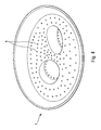
- the figure 1 is a schematic representation, greatly enlarged, of the structure of a non-preferred orientation e-PTFE used in the present invention, as seen under an electron microscope.
- the figure 2 is a schematic section of an implantable prosthesis part, for example an artificial ventricle for cardiac prosthesis with an intake duct and an ejection duct, the assembly comprising a hemocompatible e-PTFE coating according to the present invention.
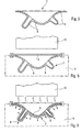
- the figure 3 shows in schematic section a forming mold for obtaining said hemocompatible coating.
- the figure 4 is a perspective view of said forming mold.
- FIGS. 5 and 6 schematically illustrate the thermoforming of a membrane made in the e-PTFE of the figure 1 to obtain said hemocompatible coating.
- the figure 7 shows in schematic section the hemocompatible coating obtained.
- FIGS 8 and 9 schematically illustrate the fastening of said hemocompatible coating on said artificial ventricle.
- FIG. 1 schematically shows the electron microscopic view of a portion of the surface of a membrane 1 in e-PTFE used in the method of the invention.
- the structure of the membrane 1 comprises a plurality of nodes 2 distributed randomly and connected by multidirectional fibers 3.
- the knots 2 nor the fibers 3 form preferentially oriented arrangements.
- E-PTFE such as the one whose structure is schematically illustrated on the figure 1 can be obtained, for example from GORE (Gore Medical Product Division, US), TERUMO (Vascutek, Japan) or BARD (Impra, US).
- FIG. 2 shows schematically a blank of artificial ventricle 4 for cardiac prosthesis, comprising a rigid shell 5, by example in a metal or a plastic material such as polyetheretherketone, etc ..., carrying a hemocompatible coating 6 which is integral therewith.
- the hemocompatible coating 6 is made from the membrane 1, as illustrated by the Figures 3 to 7 .
- a forming mold is used, such as for example that represented on the figures 3 and 4 where it bears the reference 7.
- the forming mold 7 is made of a biocompatible and thermocompatible material whose shape reproduces exactly the desired shape for the hemocompatible coating 6. It is further pierced by a plurality of vents 8.
- the membrane 1 is sealingly attached to the edges of the forming mold 7 to close it, which is connected to a vacuum source 9. Moreover, a heating device 10 is arranged opposite the membrane 1.
- the membrane 1 may be heated to a temperature above the gel point of the e-PTFE which constitutes it (of the order of 400 ° C.), and pressed against the forming mold 7 by the depression generated by the source 9 through the vents 8 (see figure 6 ).
- the heating is stopped, but the depression is maintained during the cooling of said shaped membrane.
- the cooling of said shaped membrane, maintained pressed against said forming mold 7 by the depression is accelerated, for example by blowing cold air.
- the membrane 1 in the form of a coating 6 is thermally stable and can be disengaged from the forming mold 7 (see FIG. figure 7 ).
- said coating 6 is mounted on an inflatable tool 11, for example bladder type, having a configuration identical to that of said rigid shell 5 (see figure 8 ) and can be inflated by means 12.
- an inflatable tool 11 for example bladder type, having a configuration identical to that of said rigid shell 5 (see figure 8 ) and can be inflated by means 12.
- the surfaces to be bonded to the coating 6 and / or the rigid shell 5 are coated with a layer of adhesive 14 or 15, respectively, for example silicone-based (see also figure 9 ).
- a layer of adhesive 14 or 15, respectively for example silicone-based (see also figure 9 ).
- said surfaces to be joined can be processed to improve said bonding.
- said coating 6 may be impregnated by dilution of a low viscosity elastomer, for example based on silicone. In the latter case, the solvent of said dilution is advantageously slowly removed by hot extraction and / or under vacuum.
- the assembly 6, 11, 14 is then introduced into the shell 5 to put the layers 14, 15 in contact with each other.
- the tool 11 is then inflated to allow the layers 14, 15 to be compressed and to provide a homogeneous thickness at the resulting adhesive seal.
- the artificial ventricle blank is obtained. figure 2 .
Abstract
Description
La présente invention concerne les objets hémocompatibles et, notamment, les prothèses implantables et les revêtements hémocompatibles pour de telles prothèses.The present invention relates to hemocompatible objects and, in particular, implantable prostheses and hemocompatible coatings for such prostheses.
On sait que les surfaces des dispositifs médicaux implantés, en contact direct avec le sang, ne doivent en aucun cas altérer le tissu sanguin, ni perturber le flux du sang. Elles doivent donc être parfaitement hémocompatibles.It is known that the surfaces of the implanted medical devices, in direct contact with the blood, must not in any way alter the blood tissue or disturb the flow of blood. They must be perfectly haemocompatible.
On sait, par ailleurs, que les polytétrafluoroéthylènes expansés, généralement désignés dans la technique par e-PTFE, sont largement utilisés pour la réalisation de tels objets hémocompatibles (voir, par exemple, les documents
Aussi, les objets hémocompatibles en e-PTFE que l'on peut obtenir actuellement présentent-ils obligatoirement des formes simples, telles que plaques ou tubes.Also, the hemocompatible e-PTFE objects that can currently be obtained necessarily have simple shapes, such as plates or tubes.
La présente invention a pour objet de remédier à cet inconvénient et de permettre d'obtenir des objets hémocompatibles de configuration complexe.The object of the present invention is to remedy this drawback and to make it possible to obtain haemocompatible objects of complex configuration.
A cette fin, selon l'invention, le procédé pour la réalisation d'un objet hémocompatible, procédé selon lequel :
- on réalise un moule de formage présentant la configuration dudit objet ;
- on conforme une membrane de polytétrafluoroéthylène à la configuration dudit objet en la chauffant et en l'appliquant contre ledit moule de formage au moyen d'une différence de pression engendrée entre les deux faces de ladite membrane ;
- on refroidit ladite membrane ainsi conformée tout en la maintenant appliquée contre ledit moule de formage ; et
- on dégage ladite membrane conformée dudit moule de formage, est remarquable en ce que :
- ladite membrane est réalisée en un polytétrafluoroéthylène expansé qui n'est pas stabilisé thermiquement, préalablement à sa conformation à la configuration dudit objet, et dont les fibres ne présentent aucune orientation préférentielle ; et
- ladite membrane est chauffée, pendant sa conformation à la configuration dudit objet, jusqu'à une température supérieure au point de gel dudit polytétrafluoroéthylène expansé.
- forming a forming mold having the configuration of said object;
- conforming a polytetrafluoroethylene membrane to the configuration of said object by heating it and applying it against said forming mold by means of a pressure difference generated between the two faces of said membrane;
- said membrane thus shaped is cooled while maintaining it pressed against said forming mold; and
- said shaped membrane is disengaged from said forming mold, is remarkable in that:
- said membrane is made of an expanded polytetrafluoroethylene which is not thermally stabilized, prior to its conformation to the configuration of said object, and whose fibers have no preferential orientation; and
- said membrane is heated, during its conformation to the configuration of said object, to a temperature above the gel point of said expanded polytetrafluoroethylene.
En effet, le demandeur a constaté que, jusqu'à présent, les e-PTFE utilisés pour la réalisation d'objets hémocompatibles ont une structure dans laquelle lesdites fibres présentent une orientation préférentielle et que si, au contraire, on utilise un e-PTFE dont les fibres ne présentent aucune orientation préférentielle, on peut conformer ce e-PTFE par thermoformage, comme cela est usuel pour les polytétrafluoroéthylènes ordinaires (voir, par exemple,
Grâce à la présente invention, on peut donc obtenir des objets hémocompatibles en e-PTFE présentant une forme complexe.Thanks to the present invention, one can thus obtain hemocompatible objects in e-PTFE having a complex shape.
Avantageusement, l'échauffement de ladite membrane est réalisé à l'air chaud. La température à laquelle est chauffée ladite membrane peut être de l'ordre de 400°C.Advantageously, the heating of said membrane is carried out with hot air. The temperature at which said membrane is heated may be of the order of 400 ° C.
De préférence, l'application de la membrane chauffée contre ledit moule de formage est obtenue par dépression à travers ce dernier.Preferably, the application of the heated membrane against said forming mold is obtained by depression therethrough.
De plus, ledit refroidissement de la membrane conformée peut être accéléré, par exemple par soufflage d'air froid.In addition, said cooling of the shaped membrane can be accelerated, for example by blowing cold air.
Ledit objet hémocompatible obtenu par la mise en oeuvre de la présente invention peut avantageusement former un revêtement pour une prothèse ou partie de prothèse implantable présentant ladite configuration. Dans ce cas, après dégagement, hors dudit moule de formage, de ladite membrane conformée à la configuration de ladite prothèse ou partie de prothèse, ladite membrane est collée sur cette dernière, par exemple à l'aide d'un élastomère, tel qu'un silicone.Said hemocompatible object obtained by the practice of the present invention may advantageously form a coating for a prosthesis or implantable prosthesis portion having said configuration. In this case, after disengagement, from said forming mold, of said diaphragm conforming to the configuration of said prosthesis or prosthesis portion, said membrane is bonded to the latter, for example using an elastomer, such as a silicone.
Pour le collage de la membrane conformée sur ladite prothèse ou partie de prothèse, on peut monter ladite membrane conformée sur un outillage gonflable de forme semblable et, après mise en contact de ladite membrane conformée avec ladite prothèse ou partie de prothèse avec interposition d'au moins une couche d'adhésif, ledit outillage est gonflé pour permettre la compression de cette dernière et lui assurer une épaisseur homogène.For the bonding of the membrane shaped on said prosthesis or prosthesis part, said shaped membrane can be mounted on an inflatable tool of similar shape and, after contacting said shaped membrane with said prosthesis or part of prosthesis with interposition of less a layer of adhesive, said tool is inflated to allow compression of the latter and ensure a uniform thickness.
Il va de soi que le procédé conforme à la présente invention peut être mis en oeuvre pour la réalisation d'objets hémocompatibles de toutes sortes. Toutefois, dans une application particulièrement intéressante, l'objet hémocompatible constitue un revêtement pour une prothèse cardiaque ou partie de prothèse cardiaque, telle qu'un ventricule artificiel. Ladite prothèse cardiaque est alors remarquable en ce qu'au moins l'une de ses parties comporte un tel revêtement hémocompatible.It goes without saying that the method according to the present invention can be implemented for the production of hemocompatible objects of all kinds. However, in a particularly advantageous application, the hemocompatible object constitutes a coating for a cardiac prosthesis or part of a cardiac prosthesis, such as an artificial ventricle. Said cardiac prosthesis is then remarkable in that at least one of its parts comprises such a hemocompatible coating.
Les figures du dessin annexé feront bien comprendre comment l'invention peut être réalisée. Sur ces figures, des références identiques désignent des éléments semblables.The figures of the appended drawing will make it clear how the invention can be realized. In these figures, identical references designate similar elements.
La
La
La
La
Les
La
Les
Sur la
Un e-PTFE, tel que celui dont la structure est illustrée schématiquement sur la
Un exemple d'application de la présente invention est représenté sur la
Le revêtement hémocompatible 6 est réalisé à partir de la membrane 1, de la façon illustrée par les
Pour la réalisation du revêtement 6, on utilise un moule de formage, tel que par exemple celui représenté sur les
Comme l'illustre la
Ainsi, la membrane 1 peut être chauffée à une température supérieure au point de gel de l'e-PTFE qui la constitue (de l'ordre de 400°C), et plaquée contre le moule de formage 7 par la dépression engendrée par la source 9 à travers les évents 8 (voir la
Après conformation de la membrane 1 à la forme du revêtement 6, le chauffage est arrêté, mais la dépression est maintenue pendant le refroidissement de ladite membrane conformée. Eventuellement, le refroidissement de ladite membrane conformée, maintenue plaquée contre ledit moule de formage 7 par la dépression, est accéléré, par exemple par soufflage d'air froid. Lorsque la température ambiante est atteinte, la membrane 1 conformée en revêtement 6 est thermiquement stable et peut être dégagée du moule de formage 7 (voir la
En vue de l'adhésion du revêtement 6 sur la coque rigide 5, on monte ledit revêtement 6 sur un outillage gonflable 11, par exemple du type vessie, présentant une configuration identique à cette de ladite coque rigide 5 (voir la
Ensuite, les surfaces à coller du revêtement 6 et/ou de la coque rigide 5 sont revêtues d'une couche d'adhésif 14 ou 15, respectivement, par exemple à base de silicone (voir également la
L'ensemble 6, 11, 14 est alors introduit dans la coque 5 pour mettre les couches 14, 15 au contact l'une de l'autre.The
L'outillage 11 est alors gonflé pour permettre la compression des couches 14, 15 et assurer une épaisseur homogène au joint d'adhésif qui en résulte.The
Après durcissement dudit joint et ouverture des extrémités des conduits d'admission et d'éjection, on obtient l'ébauche de ventricule artificiel de la
Claims (9)
caractérisé en ce que l'échauffement de ladite membrane est réalisé à l'air chaud.Process according to claim 1,
characterized in that the heating of said membrane is carried out with hot air.
caractérisé en ce que la température à laquelle est chauffée ladite membrane (1) est de l'ordre de 400°C.Method according to one of claims 1 or 2,
characterized in that the temperature at which said membrane (1) is heated is of the order of 400 ° C.
caractérisé en ce que ladite application de la membrane chauffée (1) contre ledit moule de formage (7) est obtenue par dépression à travers ce dernier.Method according to one of claims 1 to 3,
characterized in that said application of the heated membrane (1) against said forming mold (7) is obtained by depression therethrough.
caractérisé en ce que le refroidissement de ladite membrane conformée est accéléré.Method according to one of claims 1 to 4,
characterized in that the cooling of said shaped diaphragm is accelerated.
caractérisé en ce que, après dégagement, hors dudit moule de formage (7), de ladite membrane conformée à la configuration de ladite prothèse ou partie de prothèse, ladite membrane est collée sur cette dernière.Method according to one of the preceding claims, implemented for the production of a hemocompatible object of complex configuration to form a coating (6) for a prosthesis or implantable prosthesis part (4) having said configuration,
characterized in that , after disengagement, out of said forming mold (7), said diaphragm conforming to the configuration of said prosthesis or prosthesis portion, said membrane is bonded thereto.
caractérisé en ce que, pour le collage de la membrane conformée sur ladite prothèse ou partie de prothèse (4), on monte ladite membrane conformée sur un outillage gonflable (11) de forme semblable et, après mise en contact de ladite membrane conformée avec ladite prothèse ou partie de prothèse par l'intermédiaire d'au moins une couche d'adhésif, ledit outillage (11) est gonflé pour permettre la compression de cette dernière et lui assurer une épaisseur homogène.Process according to claim 6,
characterized in that , for bonding the shaped membrane to said prosthesis or prosthesis portion (4), said shaped diaphragm is mounted on an inflatable tool (11) of similar shape and, after contacting said shaped diaphragm with said prosthesis or part of prosthesis through at least one layer of adhesive, said tool (11) is inflated to allow compression of the latter and ensure a uniform thickness.
caractérisé en ce que ledit collage est obtenu à l'aide d'un élastomère, tel qu'un silicone.Method according to one of claims 6 or 7,
characterized in that said bonding is obtained using an elastomer, such as a silicone.
caractérisée en ce qu'au moins l'une de ses parties comporte un revêtement hémocompatible formé par la mise en oeuvre du procédé selon l'une quelconque des revendications 1 à 8.Cardiac prosthesis,
characterized in that at least one of its parts comprises a hemocompatible coating formed by carrying out the method according to any one of claims 1 to 8.
Priority Applications (1)
| Application Number | Priority Date | Filing Date | Title |
|---|---|---|---|
| PL08290405T PL1992369T3 (en) | 2007-05-10 | 2008-04-28 | Method of manufacturing a haemocompatible object with complex configuration and object thus obtained |
Applications Claiming Priority (1)
| Application Number | Priority Date | Filing Date | Title |
|---|---|---|---|
| FR0703339A FR2915903B1 (en) | 2007-05-10 | 2007-05-10 | METHOD FOR THE PRODUCTION OF A HEMOCOMPATIBLE OBJECT OF COMPLEX CONFIGURATION AND OBJECT THUS OBTAINED |
Publications (2)
| Publication Number | Publication Date |
|---|---|
| EP1992369A1 true EP1992369A1 (en) | 2008-11-19 |
| EP1992369B1 EP1992369B1 (en) | 2015-05-06 |
Family
ID=38849264
Family Applications (1)
| Application Number | Title | Priority Date | Filing Date |
|---|---|---|---|
| EP20080290405 Active EP1992369B1 (en) | 2007-05-10 | 2008-04-28 | Method of manufacturing a haemocompatible object with complex configuration and object thus obtained |
Country Status (14)
| Country | Link |
|---|---|
| US (1) | US8728264B2 (en) |
| EP (1) | EP1992369B1 (en) |
| JP (1) | JP5427777B2 (en) |
| KR (1) | KR101476160B1 (en) |
| CN (1) | CN101711169A (en) |
| AU (1) | AU2008257275B2 (en) |
| CA (1) | CA2686444C (en) |
| DK (1) | DK1992369T3 (en) |
| ES (1) | ES2542351T3 (en) |
| FR (1) | FR2915903B1 (en) |
| PL (1) | PL1992369T3 (en) |
| RU (1) | RU2430744C2 (en) |
| WO (1) | WO2008145870A2 (en) |
| ZA (1) | ZA200907664B (en) |
Families Citing this family (14)
| Publication number | Priority date | Publication date | Assignee | Title |
|---|---|---|---|---|
| US8579964B2 (en) | 2010-05-05 | 2013-11-12 | Neovasc Inc. | Transcatheter mitral valve prosthesis |
| US9308087B2 (en) | 2011-04-28 | 2016-04-12 | Neovasc Tiara Inc. | Sequentially deployed transcatheter mitral valve prosthesis |
| US9554897B2 (en) | 2011-04-28 | 2017-01-31 | Neovasc Tiara Inc. | Methods and apparatus for engaging a valve prosthesis with tissue |
| US9345573B2 (en) | 2012-05-30 | 2016-05-24 | Neovasc Tiara Inc. | Methods and apparatus for loading a prosthesis onto a delivery system |
| US9572665B2 (en) | 2013-04-04 | 2017-02-21 | Neovasc Tiara Inc. | Methods and apparatus for delivering a prosthetic valve to a beating heart |
| CN108882981B (en) | 2016-01-29 | 2021-08-10 | 内奥瓦斯克迪亚拉公司 | Prosthetic valve for preventing outflow obstruction |
| CN109996581B (en) | 2016-11-21 | 2021-10-15 | 内奥瓦斯克迪亚拉公司 | Methods and systems for rapid retrieval of transcatheter heart valve delivery systems |
| CN111263622A (en) | 2017-08-25 | 2020-06-09 | 内奥瓦斯克迪亚拉公司 | Sequentially deployed transcatheter mitral valve prosthesis |
| EP3876870B1 (en) | 2018-11-08 | 2023-12-20 | Neovasc Tiara Inc. | Ventricular deployment of a transcatheter mitral valve prosthesis |
| EP3911693A4 (en) | 2019-01-15 | 2022-08-24 | Palziv Ein Hanaziv Agricultural Cooperative Society Ltd. | Continuous open foam polymer sheet method |
| EP3946163A4 (en) | 2019-04-01 | 2022-12-21 | Neovasc Tiara Inc. | Controllably deployable prosthetic valve |
| EP3952792A4 (en) | 2019-04-10 | 2023-01-04 | Neovasc Tiara Inc. | Prosthetic valve with natural blood flow |
| CN114025813A (en) | 2019-05-20 | 2022-02-08 | 内奥瓦斯克迪亚拉公司 | Introducer with hemostatic mechanism |
| WO2020257643A1 (en) | 2019-06-20 | 2020-12-24 | Neovasc Tiara Inc. | Low profile prosthetic mitral valve |
Citations (14)
| Publication number | Priority date | Publication date | Assignee | Title |
|---|---|---|---|---|
| US4473423A (en) * | 1982-05-03 | 1984-09-25 | University Of Utah | Artificial heart valve made by vacuum forming technique |
| US4743480A (en) | 1986-11-13 | 1988-05-10 | W. L. Gore & Associates, Inc. | Apparatus and method for extruding and expanding polytetrafluoroethylene tubing and the products produced thereby |
| WO1995005277A1 (en) | 1993-08-18 | 1995-02-23 | W.L. Gore & Associates, Inc. | A thin-wall, seamless, porous polytetrafluoroethylene tube |
| WO1996000103A1 (en) | 1994-06-27 | 1996-01-04 | Endomed, Inc. | Radially expandable polytetrafluoroethylene and expandable endovascular stents formed therewith |
| EP0692264A2 (en) | 1994-07-11 | 1996-01-17 | Meadox Medicals, Inc. | Expanded PTFE implantable prosthesis with improved blood and tissue compatibility and superior patency |
| WO1996016601A1 (en) | 1994-11-30 | 1996-06-06 | W.L. Gore & Associates, Inc. | Surgical device for protecting organs from formation of adhesions |
| US5665114A (en) | 1994-08-12 | 1997-09-09 | Meadox Medicals, Inc. | Tubular expanded polytetrafluoroethylene implantable prostheses |
| US6001302A (en) * | 1995-09-22 | 1999-12-14 | Japan Gore-Tex, Inc. | Method of blow-molding an article of liquid crystal polymer and porous PTFE |
| US6039755A (en) | 1997-02-05 | 2000-03-21 | Impra, Inc., A Division Of C.R. Bard, Inc. | Radially expandable tubular polytetrafluoroethylene grafts and method of making same |
| US6440164B1 (en) * | 1999-10-21 | 2002-08-27 | Scimed Life Systems, Inc. | Implantable prosthetic valve |
| WO2002100454A1 (en) | 2001-06-11 | 2002-12-19 | Boston Scientific Limited | COMPOSITE ePTFE/TEXTILE PROSTHESIS |
| RU2202990C2 (en) * | 2000-12-06 | 2003-04-27 | Научно-производственное предприятие "МЕДИНЖ" | Heart valve prosthesis |
| WO2003093356A1 (en) | 2002-05-02 | 2003-11-13 | Sumitomo Electric Industries, Ltd. | Stretched polytetrafluoroethylene moldings and process for production thereof |
| US20040210307A1 (en) * | 2003-04-18 | 2004-10-21 | Alexander Khairkhahan | Percutaneous transcatheter heart valve replacement |
Family Cites Families (10)
| Publication number | Priority date | Publication date | Assignee | Title |
|---|---|---|---|---|
| US3406685A (en) * | 1963-07-23 | 1968-10-22 | Becton Dickinson Co | Catheter needle and method for its manufacture |
| CA962021A (en) * | 1970-05-21 | 1975-02-04 | Robert W. Gore | Porous products and process therefor |
| US6016848A (en) * | 1996-07-16 | 2000-01-25 | W. L. Gore & Associates, Inc. | Fluoropolymer tubes and methods of making same |
| US7560006B2 (en) * | 2001-06-11 | 2009-07-14 | Boston Scientific Scimed, Inc. | Pressure lamination method for forming composite ePTFE/textile and ePTFE/stent/textile prostheses |
| US7597775B2 (en) * | 2001-10-30 | 2009-10-06 | Boston Scientific Scimed, Inc. | Green fluoropolymer tube and endovascular prosthesis formed using same |
| US7125464B2 (en) * | 2001-12-20 | 2006-10-24 | Boston Scientific Santa Rosa Corp. | Method for manufacturing an endovascular graft section |
| US6737158B1 (en) * | 2002-10-30 | 2004-05-18 | Gore Enterprise Holdings, Inc. | Porous polymeric membrane toughened composites |
| US20050222675A1 (en) * | 2004-04-06 | 2005-10-06 | Sauter Joseph A | Implantable prosthetic heart valve comprising a valve body and a tubular vascular graft |
| US7524445B2 (en) * | 2004-12-31 | 2009-04-28 | Boston Scientific Scimed, Inc. | Method for making ePTFE and structure containing such ePTFE, such as a vascular graft |
| US8257431B2 (en) * | 2006-11-01 | 2012-09-04 | Boston Scientific Scimed, Inc. | Multi-furcated ePTFE grafts and stent-graft prostheses and methods of making the same |
-
2007
- 2007-05-10 FR FR0703339A patent/FR2915903B1/en active Active
-
2008
- 2008-04-28 EP EP20080290405 patent/EP1992369B1/en active Active
- 2008-04-28 AU AU2008257275A patent/AU2008257275B2/en active Active
- 2008-04-28 ES ES08290405.3T patent/ES2542351T3/en active Active
- 2008-04-28 PL PL08290405T patent/PL1992369T3/en unknown
- 2008-04-28 JP JP2010506963A patent/JP5427777B2/en active Active
- 2008-04-28 DK DK08290405.3T patent/DK1992369T3/en active
- 2008-04-28 KR KR1020097025669A patent/KR101476160B1/en active IP Right Grant
- 2008-04-28 WO PCT/FR2008/000607 patent/WO2008145870A2/en active Application Filing
- 2008-04-28 CN CN200880015494A patent/CN101711169A/en active Pending
- 2008-04-28 CA CA 2686444 patent/CA2686444C/en active Active
- 2008-04-28 US US12/599,501 patent/US8728264B2/en active Active
- 2008-04-28 RU RU2009145704A patent/RU2430744C2/en active
-
2009
- 2009-11-02 ZA ZA200907664A patent/ZA200907664B/en unknown
Patent Citations (14)
| Publication number | Priority date | Publication date | Assignee | Title |
|---|---|---|---|---|
| US4473423A (en) * | 1982-05-03 | 1984-09-25 | University Of Utah | Artificial heart valve made by vacuum forming technique |
| US4743480A (en) | 1986-11-13 | 1988-05-10 | W. L. Gore & Associates, Inc. | Apparatus and method for extruding and expanding polytetrafluoroethylene tubing and the products produced thereby |
| WO1995005277A1 (en) | 1993-08-18 | 1995-02-23 | W.L. Gore & Associates, Inc. | A thin-wall, seamless, porous polytetrafluoroethylene tube |
| WO1996000103A1 (en) | 1994-06-27 | 1996-01-04 | Endomed, Inc. | Radially expandable polytetrafluoroethylene and expandable endovascular stents formed therewith |
| EP0692264A2 (en) | 1994-07-11 | 1996-01-17 | Meadox Medicals, Inc. | Expanded PTFE implantable prosthesis with improved blood and tissue compatibility and superior patency |
| US5665114A (en) | 1994-08-12 | 1997-09-09 | Meadox Medicals, Inc. | Tubular expanded polytetrafluoroethylene implantable prostheses |
| WO1996016601A1 (en) | 1994-11-30 | 1996-06-06 | W.L. Gore & Associates, Inc. | Surgical device for protecting organs from formation of adhesions |
| US6001302A (en) * | 1995-09-22 | 1999-12-14 | Japan Gore-Tex, Inc. | Method of blow-molding an article of liquid crystal polymer and porous PTFE |
| US6039755A (en) | 1997-02-05 | 2000-03-21 | Impra, Inc., A Division Of C.R. Bard, Inc. | Radially expandable tubular polytetrafluoroethylene grafts and method of making same |
| US6440164B1 (en) * | 1999-10-21 | 2002-08-27 | Scimed Life Systems, Inc. | Implantable prosthetic valve |
| RU2202990C2 (en) * | 2000-12-06 | 2003-04-27 | Научно-производственное предприятие "МЕДИНЖ" | Heart valve prosthesis |
| WO2002100454A1 (en) | 2001-06-11 | 2002-12-19 | Boston Scientific Limited | COMPOSITE ePTFE/TEXTILE PROSTHESIS |
| WO2003093356A1 (en) | 2002-05-02 | 2003-11-13 | Sumitomo Electric Industries, Ltd. | Stretched polytetrafluoroethylene moldings and process for production thereof |
| US20040210307A1 (en) * | 2003-04-18 | 2004-10-21 | Alexander Khairkhahan | Percutaneous transcatheter heart valve replacement |
Non-Patent Citations (1)
| Title |
|---|
| DATABASE WPI Week 200338, Derwent World Patents Index; AN 2003-400764, XP002463567 * |
Also Published As
| Publication number | Publication date |
|---|---|
| DK1992369T3 (en) | 2015-07-20 |
| JP2010526573A (en) | 2010-08-05 |
| CN101711169A (en) | 2010-05-19 |
| WO2008145870A3 (en) | 2009-02-19 |
| EP1992369B1 (en) | 2015-05-06 |
| WO2008145870A2 (en) | 2008-12-04 |
| WO2008145870A8 (en) | 2009-08-06 |
| KR101476160B1 (en) | 2014-12-24 |
| JP5427777B2 (en) | 2014-02-26 |
| CA2686444C (en) | 2014-07-15 |
| RU2430744C2 (en) | 2011-10-10 |
| PL1992369T3 (en) | 2015-10-30 |
| US8728264B2 (en) | 2014-05-20 |
| KR20100017723A (en) | 2010-02-16 |
| AU2008257275B2 (en) | 2013-09-26 |
| ZA200907664B (en) | 2010-07-28 |
| FR2915903B1 (en) | 2010-06-04 |
| FR2915903A1 (en) | 2008-11-14 |
| ES2542351T3 (en) | 2015-08-04 |
| AU2008257275A1 (en) | 2008-12-04 |
| CA2686444A1 (en) | 2008-12-04 |
| RU2009145704A (en) | 2011-06-20 |
| US20110244246A1 (en) | 2011-10-06 |
Similar Documents
| Publication | Publication Date | Title |
|---|---|---|
| EP1992369B1 (en) | Method of manufacturing a haemocompatible object with complex configuration and object thus obtained | |
| US20130172914A1 (en) | Surgical clip | |
| CA2930813A1 (en) | Method for impregnation of a fibrous preform and device for implementation of the said method | |
| EP0657554B1 (en) | Process for preparing a circular fiberreinforced metallic workpiece | |
| FR2994078A1 (en) | METHOD FOR MANUFACTURING A PROTHETIC CUSTOM SLEEVE | |
| EP0015181B1 (en) | Process for the moulding of articles from synthetic material | |
| EP1880827B1 (en) | Method of thermoforming used to obtain complex shapes | |
| EP3022031B1 (en) | Method for shaping a board made from a sintered and restructured polytetrafluoroethylene. | |
| CH711914B1 (en) | Method for manufacturing a carbon fiber watch case and carbon fiber watch case obtained by this method. | |
| FR2985213A1 (en) | SELF-RAIDI COMPOSITE PANEL AND METHOD OF MAKING SAME | |
| FR2989620A1 (en) | METHOD AND DEVICE FOR POSITIONING INSERTS IN A MOLD FOR PLASTIC MATERIALS | |
| FR2490993A3 (en) | Reusable mould for making complex hollow reinforced profiles - using an inflatable core in split rigid external mould | |
| WO2002059061A1 (en) | Method for making a carbon/carbon crucible holder and resulting crucible stand | |
| FR2750640A1 (en) | Production of fibre reinforced plastic parts | |
| FR3028704A1 (en) | SPEAKER MEMBRANE, AND METHOD FOR MANUFACTURING SUCH MEMBRANE | |
| FR3076481A1 (en) | PROCESS FOR OBTAINING THREE DIMENSIONAL COMPOSITE PIECE AND PRESS FOR CARRYING OUT THE PROCESS | |
| EP3773353B1 (en) | Method for manufacturing a customised sleeve for a prosthesis | |
| FR3030344A1 (en) | <P> METHOD FOR PREPARING THE DRAPING OF A FORM COMPOSITE PREFORM </ P> | |
| CA3155691A1 (en) | Method for manufacturing a thermoformable foam air duct | |
| FR2870463A1 (en) | Compound material as a splint for a human/animal limb, and especially the tibia, is a core fabric impregnated with a resin for heat shaping with both surfaces covered by a non-stick film | |
| FR2725660A1 (en) | Prodn. of soft lens intra:ocular implant | |
| FR2869384A1 (en) | Fluid transporting pipe e.g. for aircraft air conditioning duct is made from resin-impregnated fabric with internal plastic film lining | |
| FR2642357A1 (en) | Method of manufacturing a moulded element made of elastomer, by means of a vacuum | |
| CH711381A2 (en) | A part comprising an amorphous metal alloy foam part and a manufacturing method. | |
| FR2725659A1 (en) | Prodn. of soft lens intra:ocular implant |
Legal Events
| Date | Code | Title | Description |
|---|---|---|---|
| PUAI | Public reference made under article 153(3) epc to a published international application that has entered the european phase |
Free format text: ORIGINAL CODE: 0009012 |
|
| AK | Designated contracting states |
Kind code of ref document: A1 Designated state(s): AT BE BG CH CY CZ DE DK EE ES FI FR GB GR HR HU IE IS IT LI LT LU LV MC MT NL NO PL PT RO SE SI SK TR |
|
| AX | Request for extension of the european patent |
Extension state: AL BA MK RS |
|
| 17P | Request for examination filed |
Effective date: 20081206 |
|
| 17Q | First examination report despatched |
Effective date: 20090119 |
|
| RAP1 | Party data changed (applicant data changed or rights of an application transferred) |
Owner name: ASSOCIATION RECHERCHE SCIENTIFIQUE DE LA FONDATION Owner name: MATRA DEFENSE |
|
| RAP1 | Party data changed (applicant data changed or rights of an application transferred) |
Owner name: CARMAT |
|
| AKX | Designation fees paid |
Designated state(s): AT BE BG CH CY CZ DE DK EE ES FI FR GB GR HR HU IE IS IT LI LT LU LV MC MT NL NO PL PT RO SE SI SK TR |
|
| RAP1 | Party data changed (applicant data changed or rights of an application transferred) |
Owner name: CARMAT |
|
| GRAP | Despatch of communication of intention to grant a patent |
Free format text: ORIGINAL CODE: EPIDOSNIGR1 |
|
| INTG | Intention to grant announced |
Effective date: 20141201 |
|
| GRAS | Grant fee paid |
Free format text: ORIGINAL CODE: EPIDOSNIGR3 |
|
| GRAA | (expected) grant |
Free format text: ORIGINAL CODE: 0009210 |
|
| AK | Designated contracting states |
Kind code of ref document: B1 Designated state(s): AT BE BG CH CY CZ DE DK EE ES FI FR GB GR HR HU IE IS IT LI LT LU LV MC MT NL NO PL PT RO SE SI SK TR |
|
| REG | Reference to a national code |
Ref country code: GB Ref legal event code: FG4D Free format text: NOT ENGLISH |
|
| REG | Reference to a national code |
Ref country code: CH Ref legal event code: EP |
|
| REG | Reference to a national code |
Ref country code: IE Ref legal event code: FG4D Free format text: LANGUAGE OF EP DOCUMENT: FRENCH |
|
| REG | Reference to a national code |
Ref country code: AT Ref legal event code: REF Ref document number: 725251 Country of ref document: AT Kind code of ref document: T Effective date: 20150615 |
|
| REG | Reference to a national code |
Ref country code: DE Ref legal event code: R096 Ref document number: 602008038028 Country of ref document: DE Effective date: 20150618 |
|
| REG | Reference to a national code |
Ref country code: NL Ref legal event code: T3 |
|
| REG | Reference to a national code |
Ref country code: DK Ref legal event code: T3 Effective date: 20150716 |
|
| REG | Reference to a national code |
Ref country code: SE Ref legal event code: TRGR |
|
| REG | Reference to a national code |
Ref country code: ES Ref legal event code: FG2A Ref document number: 2542351 Country of ref document: ES Kind code of ref document: T3 Effective date: 20150804 |
|
| REG | Reference to a national code |
Ref country code: NO Ref legal event code: T2 Effective date: 20150506 |
|
| REG | Reference to a national code |
Ref country code: NO Ref legal event code: CREP Representative=s name: BRYN AARFLOT AS, POSTBOKS 449 SENTRUM, 0104 OSLO |
|
| REG | Reference to a national code |
Ref country code: LT Ref legal event code: MG4D |
|
| PG25 | Lapsed in a contracting state [announced via postgrant information from national office to epo] |
Ref country code: LT Free format text: LAPSE BECAUSE OF FAILURE TO SUBMIT A TRANSLATION OF THE DESCRIPTION OR TO PAY THE FEE WITHIN THE PRESCRIBED TIME-LIMIT Effective date: 20150506 Ref country code: HR Free format text: LAPSE BECAUSE OF FAILURE TO SUBMIT A TRANSLATION OF THE DESCRIPTION OR TO PAY THE FEE WITHIN THE PRESCRIBED TIME-LIMIT Effective date: 20150506 Ref country code: PT Free format text: LAPSE BECAUSE OF FAILURE TO SUBMIT A TRANSLATION OF THE DESCRIPTION OR TO PAY THE FEE WITHIN THE PRESCRIBED TIME-LIMIT Effective date: 20150907 Ref country code: FI Free format text: LAPSE BECAUSE OF FAILURE TO SUBMIT A TRANSLATION OF THE DESCRIPTION OR TO PAY THE FEE WITHIN THE PRESCRIBED TIME-LIMIT Effective date: 20150506 |
|
| REG | Reference to a national code |
Ref country code: PL Ref legal event code: T3 |
|
| REG | Reference to a national code |
Ref country code: GR Ref legal event code: EP Ref document number: 20150401665 Country of ref document: GR Effective date: 20150929 |
|
| PG25 | Lapsed in a contracting state [announced via postgrant information from national office to epo] |
Ref country code: BG Free format text: LAPSE BECAUSE OF FAILURE TO SUBMIT A TRANSLATION OF THE DESCRIPTION OR TO PAY THE FEE WITHIN THE PRESCRIBED TIME-LIMIT Effective date: 20150806 Ref country code: LV Free format text: LAPSE BECAUSE OF FAILURE TO SUBMIT A TRANSLATION OF THE DESCRIPTION OR TO PAY THE FEE WITHIN THE PRESCRIBED TIME-LIMIT Effective date: 20150506 Ref country code: IS Free format text: LAPSE BECAUSE OF FAILURE TO SUBMIT A TRANSLATION OF THE DESCRIPTION OR TO PAY THE FEE WITHIN THE PRESCRIBED TIME-LIMIT Effective date: 20150906 |
|
| PG25 | Lapsed in a contracting state [announced via postgrant information from national office to epo] |
Ref country code: EE Free format text: LAPSE BECAUSE OF FAILURE TO SUBMIT A TRANSLATION OF THE DESCRIPTION OR TO PAY THE FEE WITHIN THE PRESCRIBED TIME-LIMIT Effective date: 20150506 |
|
| REG | Reference to a national code |
Ref country code: DE Ref legal event code: R097 Ref document number: 602008038028 Country of ref document: DE |
|
| PG25 | Lapsed in a contracting state [announced via postgrant information from national office to epo] |
Ref country code: SK Free format text: LAPSE BECAUSE OF FAILURE TO SUBMIT A TRANSLATION OF THE DESCRIPTION OR TO PAY THE FEE WITHIN THE PRESCRIBED TIME-LIMIT Effective date: 20150506 Ref country code: CZ Free format text: LAPSE BECAUSE OF FAILURE TO SUBMIT A TRANSLATION OF THE DESCRIPTION OR TO PAY THE FEE WITHIN THE PRESCRIBED TIME-LIMIT Effective date: 20150506 Ref country code: RO Free format text: LAPSE BECAUSE OF NON-PAYMENT OF DUE FEES Effective date: 20150506 |
|
| PLBE | No opposition filed within time limit |
Free format text: ORIGINAL CODE: 0009261 |
|
| STAA | Information on the status of an ep patent application or granted ep patent |
Free format text: STATUS: NO OPPOSITION FILED WITHIN TIME LIMIT |
|
| REG | Reference to a national code |
Ref country code: AT Ref legal event code: UEP Ref document number: 725251 Country of ref document: AT Kind code of ref document: T Effective date: 20150506 |
|
| 26N | No opposition filed |
Effective date: 20160209 |
|
| REG | Reference to a national code |
Ref country code: FR Ref legal event code: PLFP Year of fee payment: 9 |
|
| PG25 | Lapsed in a contracting state [announced via postgrant information from national office to epo] |
Ref country code: SI Free format text: LAPSE BECAUSE OF FAILURE TO SUBMIT A TRANSLATION OF THE DESCRIPTION OR TO PAY THE FEE WITHIN THE PRESCRIBED TIME-LIMIT Effective date: 20150506 |
|
| PG25 | Lapsed in a contracting state [announced via postgrant information from national office to epo] |
Ref country code: LU Free format text: LAPSE BECAUSE OF FAILURE TO SUBMIT A TRANSLATION OF THE DESCRIPTION OR TO PAY THE FEE WITHIN THE PRESCRIBED TIME-LIMIT Effective date: 20160428 |
|
| REG | Reference to a national code |
Ref country code: FR Ref legal event code: PLFP Year of fee payment: 10 |
|
| REG | Reference to a national code |
Ref country code: FR Ref legal event code: PLFP Year of fee payment: 11 |
|
| PG25 | Lapsed in a contracting state [announced via postgrant information from national office to epo] |
Ref country code: HU Free format text: LAPSE BECAUSE OF FAILURE TO SUBMIT A TRANSLATION OF THE DESCRIPTION OR TO PAY THE FEE WITHIN THE PRESCRIBED TIME-LIMIT; INVALID AB INITIO Effective date: 20080428 Ref country code: CY Free format text: LAPSE BECAUSE OF FAILURE TO SUBMIT A TRANSLATION OF THE DESCRIPTION OR TO PAY THE FEE WITHIN THE PRESCRIBED TIME-LIMIT Effective date: 20150506 |
|
| PG25 | Lapsed in a contracting state [announced via postgrant information from national office to epo] |
Ref country code: MT Free format text: LAPSE BECAUSE OF FAILURE TO SUBMIT A TRANSLATION OF THE DESCRIPTION OR TO PAY THE FEE WITHIN THE PRESCRIBED TIME-LIMIT Effective date: 20150506 Ref country code: MC Free format text: LAPSE BECAUSE OF FAILURE TO SUBMIT A TRANSLATION OF THE DESCRIPTION OR TO PAY THE FEE WITHIN THE PRESCRIBED TIME-LIMIT Effective date: 20150506 |
|
| PGFP | Annual fee paid to national office [announced via postgrant information from national office to epo] |
Ref country code: NO Payment date: 20230324 Year of fee payment: 16 Ref country code: IE Payment date: 20230321 Year of fee payment: 16 Ref country code: DK Payment date: 20230327 Year of fee payment: 16 |
|
| PGFP | Annual fee paid to national office [announced via postgrant information from national office to epo] |
Ref country code: PL Payment date: 20230323 Year of fee payment: 16 Ref country code: GR Payment date: 20230320 Year of fee payment: 16 |
|
| PGFP | Annual fee paid to national office [announced via postgrant information from national office to epo] |
Ref country code: NL Payment date: 20230327 Year of fee payment: 16 |
|
| PGFP | Annual fee paid to national office [announced via postgrant information from national office to epo] |
Ref country code: IT Payment date: 20230412 Year of fee payment: 16 Ref country code: FR Payment date: 20230425 Year of fee payment: 16 Ref country code: ES Payment date: 20230504 Year of fee payment: 16 Ref country code: DE Payment date: 20230412 Year of fee payment: 16 Ref country code: CH Payment date: 20230502 Year of fee payment: 16 |
|
| PGFP | Annual fee paid to national office [announced via postgrant information from national office to epo] |
Ref country code: TR Payment date: 20230412 Year of fee payment: 16 Ref country code: SE Payment date: 20230424 Year of fee payment: 16 Ref country code: AT Payment date: 20230321 Year of fee payment: 16 |
|
| PGFP | Annual fee paid to national office [announced via postgrant information from national office to epo] |
Ref country code: BE Payment date: 20230424 Year of fee payment: 16 |
|
| PGFP | Annual fee paid to national office [announced via postgrant information from national office to epo] |
Ref country code: GB Payment date: 20230424 Year of fee payment: 16 |