EP1992298A2 - Flexible cannula with associated seal - Google Patents
Flexible cannula with associated seal Download PDFInfo
- Publication number
- EP1992298A2 EP1992298A2 EP08251708A EP08251708A EP1992298A2 EP 1992298 A2 EP1992298 A2 EP 1992298A2 EP 08251708 A EP08251708 A EP 08251708A EP 08251708 A EP08251708 A EP 08251708A EP 1992298 A2 EP1992298 A2 EP 1992298A2
- Authority
- EP
- European Patent Office
- Prior art keywords
- seal
- cannula
- flexible portion
- instrument
- longitudinal axis
- Prior art date
- Legal status (The legal status is an assumption and is not a legal conclusion. Google has not performed a legal analysis and makes no representation as to the accuracy of the status listed.)
- Granted
Links
- 244000261422 Lysimachia clethroides Species 0.000 claims abstract description 5
- 239000013536 elastomeric material Substances 0.000 claims description 4
- 239000012530 fluid Substances 0.000 description 7
- 239000007789 gas Substances 0.000 description 5
- 230000007246 mechanism Effects 0.000 description 5
- 241001631457 Cannula Species 0.000 description 2
- 210000003815 abdominal wall Anatomy 0.000 description 2
- 230000001010 compromised effect Effects 0.000 description 2
- 239000004744 fabric Substances 0.000 description 2
- 238000003780 insertion Methods 0.000 description 2
- 230000037431 insertion Effects 0.000 description 2
- 238000000034 method Methods 0.000 description 2
- 208000005646 Pneumoperitoneum Diseases 0.000 description 1
- 210000000683 abdominal cavity Anatomy 0.000 description 1
- 238000002357 laparoscopic surgery Methods 0.000 description 1
- 239000000463 material Substances 0.000 description 1
- 239000002184 metal Substances 0.000 description 1
- 238000002324 minimally invasive surgery Methods 0.000 description 1
- 238000012978 minimally invasive surgical procedure Methods 0.000 description 1
- 238000012986 modification Methods 0.000 description 1
- 230000004048 modification Effects 0.000 description 1
- 210000003200 peritoneal cavity Anatomy 0.000 description 1
- 229920000642 polymer Polymers 0.000 description 1
- 239000012858 resilient material Substances 0.000 description 1
- 239000000523 sample Substances 0.000 description 1
- 238000007789 sealing Methods 0.000 description 1
- 238000001356 surgical procedure Methods 0.000 description 1
- 210000001835 viscera Anatomy 0.000 description 1
Images


Classifications
-
- A—HUMAN NECESSITIES
- A61—MEDICAL OR VETERINARY SCIENCE; HYGIENE
- A61B—DIAGNOSIS; SURGERY; IDENTIFICATION
- A61B17/00—Surgical instruments, devices or methods, e.g. tourniquets
- A61B17/34—Trocars; Puncturing needles
- A61B17/3417—Details of tips or shafts, e.g. grooves, expandable, bendable; Multiple coaxial sliding cannulas, e.g. for dilating
- A61B17/3421—Cannulas
- A61B17/3439—Cannulas with means for changing the inner diameter of the cannula, e.g. expandable
-
- A—HUMAN NECESSITIES
- A61—MEDICAL OR VETERINARY SCIENCE; HYGIENE
- A61B—DIAGNOSIS; SURGERY; IDENTIFICATION
- A61B17/00—Surgical instruments, devices or methods, e.g. tourniquets
- A61B17/34—Trocars; Puncturing needles
- A61B17/3462—Trocars; Puncturing needles with means for changing the diameter or the orientation of the entrance port of the cannula, e.g. for use with different-sized instruments, reduction ports, adapter seals
-
- A—HUMAN NECESSITIES
- A61—MEDICAL OR VETERINARY SCIENCE; HYGIENE
- A61B—DIAGNOSIS; SURGERY; IDENTIFICATION
- A61B17/00—Surgical instruments, devices or methods, e.g. tourniquets
- A61B17/34—Trocars; Puncturing needles
- A61B17/3417—Details of tips or shafts, e.g. grooves, expandable, bendable; Multiple coaxial sliding cannulas, e.g. for dilating
- A61B17/3421—Cannulas
- A61B17/3439—Cannulas with means for changing the inner diameter of the cannula, e.g. expandable
- A61B2017/3441—Cannulas with means for changing the inner diameter of the cannula, e.g. expandable with distal sealing means
-
- A—HUMAN NECESSITIES
- A61—MEDICAL OR VETERINARY SCIENCE; HYGIENE
- A61B—DIAGNOSIS; SURGERY; IDENTIFICATION
- A61B17/00—Surgical instruments, devices or methods, e.g. tourniquets
- A61B17/34—Trocars; Puncturing needles
- A61B17/3417—Details of tips or shafts, e.g. grooves, expandable, bendable; Multiple coaxial sliding cannulas, e.g. for dilating
- A61B17/3421—Cannulas
- A61B2017/3443—Cannulas with means for adjusting the length of a cannula
Definitions
- the present disclosure relates generally to a system for accessing the body, and, more particularly, relates to a cannula having a seal and an associated flexible body portion adapted to permit lateral, angular or longitudinal movement of an inserted instrument while also preserving the sealed relation of the seal about the instrument during its manipulation.
- Surgical cannulas are employed in various minimally invasive procedures including laparoscopic or endoscopic procedures.
- Such cannulas each typically incorporate a rigid tubular member and a seal mechanism.
- the seal mechanism is intended to form a fluid tight seal about an instrument or hand passed through the tubular member.
- the seal mechanism is often limited by its ability to sustain a seal when an instrument is moved off-axis relative to a central axis of the cannula.
- the seal mechanisms are also limited by their ability to sustain their integrity when the surgical instrument is angulated.
- due to the rigidity of the tubular member of the cannula offset manipulation of the inserted instrument is restricted.
- the present disclosure is directed to a cannula assembly including a housing and a cannula member connected to the housing.
- the cannula member has leading and trailing ends and defining a longitudinal axis.
- the cannula member further includes a main body, a seal adjacent the leading end and a flexible portion disposed between the main body and the seal.
- the seal is capable of receiving an instrument therethrough while maintaining a substantial sealed relation with the instrument.
- the flexible portion is configured to permit movement of the seal relative to the longitudinal axis during manipulation of the endoscopic instrument.
- the flexible portion of the cannula member may include one or more bellows.
- the one or more bellows may form a goose neck configuration. Alternatively, the one or more bellows define a series of ridges and grooves.
- the flexible portion is adapted to permit angular movement of the seal relative to the longitudinal axis.
- the flexible portion may be adapted to permit lateral movement of the seal relative to the longitudinal axis.
- the flexible portion may be adapted to permit lateral and angular movement of the seal relative to the longitudinal axis.
- the flexible portion may be adapted to permit longitudinal movement of the seal relative to the longitudinal axis.
- the seal may be adapted to substantially close in the absence of an instrument.
- the cannula in another embodiment, includes a cannula member defining a central axis and having proximal and distal ends.
- the cannula member includes a main body adjacent the proximal end of the cannula member, a universal seal adjacent the distal end of the cannula member and a generally flexible portion disposed between the main body and the universal seal.
- the universal seal may be adapted to form a substantial sealed relation about a surgical object advanced through the cannula member and is further adapted to substantially close in the absence of the surgical object.
- the flexible portion may be adapted to permit movement of the universal seal relative to the central axis upon manipulation of the surgical object.
- the flexible body portion may define at least one bellows.
- the flexible body portion may comprise an elastomeric material.
- the flexible body portion may be adapted to permit lateral movement of the universal seal relative to the central axis.
- the flexible body portion may be adapted to permit angular movement of the universal seal relative to the central axis.
- the flexible portion may be adapted to permit each of angular and lateral movement of the universal seal relative to the central axis.
- the flexible portion is adapted to permit longitudinal movement of the seal relative to the longitudinal axis.
- the cannula of the present disclosure is capable of accommodating objects of varying diameters, e.g., including instruments from about 4.5 millimeter (mm) to about 15 millimeter (mm), during a minimally invasive surgical procedure.
- the cannula contemplates the introduction and manipulation of various types of instrumentation adapted for insertion through a trocar and/or cannula assembly while maintaining a fluid tight interface about the instrumentation to prevent gas and/or fluid leakage from the established pneumoperitoneum so as to preserve the atmospheric integrity of a surgical procedure.
- the cannula includes a flexible body portion and associated distal seal which permits angular manipulation of the surgical instrument while maintaining or preserving the sealing relation formed by the seal about the instrument. This feature of the present disclosure desirably minimizes the entry and exit of gases and/or fluids to/from the body cavity and also provides enhanced capability of instrument manipulation within the operative site.
- proximal will refer to the portion of the access apparatus nearest to the clinician during operation while the term “distal” will refer to that portion of the access apparatus most remote to the clinician.
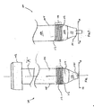
- FIG. 1 illustrates the trocar cannula of the present disclosure.
- Cannula 100 may be any member suitable for the intended purpose of accessing a body cavity and typically defines a passageway permitting introduction of instruments or the clinician's hand therethrough.
- Cannula 100 is particularly adapted for use in laparoscopic surgery where the peritoneal cavity is insufflated with a suitable gas, e.g., CO 2 , to raise the cavity wall from the internal organs therein.
- a suitable gas e.g., CO 2
- Cannula 100 is typically used with an obturator assembly (not shown) which may be blunt, a non-bladed, or a sharp pointed instrument positionable within the passageway of the cannula 100.
- the obturator assembly is utilized to penetrate the abdominal wall to introduce the cannula 100 through the abdominal wall, and then subsequently is removed from the cannula 100 to permit introduction of the surgical instrumentation utilized to perform the procedure through the passageway.
- cannula 100 includes housing 102 and cannula member 104 extending distally from the housing 102.
- Either or both housing 102 and cannula member 104 may be transparent in part or in whole and may be fabricated from biocompatible metal or polymeric material.
- Housing 102 typically incorporates at least one internal seal which is adapted to form a fluid tight seal about an instrument inserted through the housing 102.
- One suitable seal may be the fabric seal disclosed in commonly assigned U.S. Patent No. 6,702,787, which issued March 9, 2004 , the entire contents of which are incorporated herein by reference.
- the seal disclosed in the '787 patent may be a flat septum seal having a first layer of resilient material and a second fabric layer juxtaposed relative to the first layer. Further details of the seal may be ascertained by reference to the '787 patent.
- Housing 102 may include an internal seal such as a duck-bill valve or other zero closure valve adapted to close in the absence of a surgical instrument to prevent passage of insufflation gases through the housing 102.
- trocar cannula 100 is devoid of either or both an internal seal and a zero closure valve.
- cannula member 104 includes main body 106 adjacent housing 102, flexible portion 108 connected to the main body 106 and universal seal 110 which is distal of the flexible portion 108.
- Main body 106 may be substantially rigid and defines central longitudinal axis "k". Alternatively, main body 106 may have some degree of flexibility.
- Flexible portion 108 is relatively flexible to permit a range of motion of universal seal 110. Such motion of universal seal 110 is inclusive of angulated motion, lateral motion and/or longitudinal motion with respect to the central longitudinal axis "k".
- flexible portion 108 includes a bellows or goose-neck arrangement defined by at least one or a plurality or series of continuous bellows 112 or alternating convexities/ridges and concavities/recesses. Continuous bellows 112 of flexible portion 108 are adapted to angulate, longitudinally extend and/or move laterally relative to each other to permit corresponding movement of universal seal 110 relative to the central longitudinal axis "k" during manipulation of the instrument.
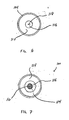
- Universal seal 110 may be adapted to close in the absence of an instrument to prevent passage of fluids, e.g., insufflation gases therethrough, e.g., to thereby assist in maintaining the integrity of the insufflated body cavity, e.g., the abdominal cavity.
- Universal seal 110 includes outer portion 114 and inner seal portion 116. Outer portion 114 is connected to flexible portion 112 of cannula member 104 through conventional means. Outer portion 114 may be composed of an elastomeric material, plastic, polymer, or the like.
- Outer portion 114 forms a tapered element depending from flexible portion 112 and is arranged to normally bias inner seal portion 116 radially inwardly to the closed position depicted in FIG. 3 . Outer portion 114 also may bias inner seal portion 116 into a position in general longitudinal alignment with longitudinal axis "k". Although inner seal portion 116 is shown positioned along longitudinal axis "k", it is envisioned that the universal seal may be positioned anywhere within the diameter of cannula member 104, and may or may not be aligned with the longitudinal axis "k"
- Inner seal portion.116 is substantially flexible or resilient, and is adapted to form a substantial fluid tight seal about an instrument inserted through the inner seal portion 114.
- inner seal portion 116 In a first or initial state, e.g., in the absence of an instrument inserted therethrough, inner seal portion 116 is closed, forming an air-tight seal as effected through the biasing action of, e.g., outer portion 114.
- the inner seal portion 116 may stretch or expand to accommodate instrument 10 while maintaining an air-tight seal thereabout.
- Inner seal portion 116 may be configured such that an increased seal surface area is achieved upon insertion of distal end 12 of instrument 10 therethrough.
- Inner seal portion 116 may be fabricated from an elastomeric material and may be integrally or monolithically formed with outer portion 114 of universal seal 110. Inner seal portion 116 may define slit 118 adapted to open to permit passage of the instrument 10. In the alternative, inner seal portion 116 may define an aperture (not shown).
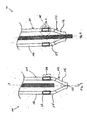
- any angular movement thereof may be translated to distal end 12 of the instrument.
- distal end 12 is angled relative to axis "k" of cannula member 104 through a predetermined angle "b"
- bellows 112 of flexible portion 108 extend and/or retract accordingly to permit movement of universal seal 110 with distal end 12 of instrument 10.
- the a substantial amount of seal surface area of inner seal portion 116 remains in contact about instrument 10 throughout the range of manipulation, thereby ensuring that the integrity of the seal is not compromised.
- flexible portion 108 of cannula 100 may also be configured to permit lateral manipulation of distal end 12 of instrument 10 while maintaining the integrity of the seal thereabout.
- proximal end (not shown) of instrument 10 is moved laterally within cannula 100 relative to axis "k" of cannula member 104
- distal end 12 of instrument 10 may be correspondingly moved with the inner seal portion 114 of universal seal 110 also being shifted in a lateral direction.
- bellows 112 of flexible portion 108 extend or stretch to accommodate the lateral movement.
- inner seal portion 116 maintains contact about instrument 10 throughout the range of manipulation, thereby ensuring that the integrity of the seal is not compromised. Both lateral and angular movement of instrument 10 and universal seal 110 is envisioned.
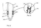
- FIGS. 11-12 illustrate an alternate embodiment where bellows 112 of flexible portion 108 of cannula member 104 is adapted to permit longitudinal movement of the flexible portion. More specifically bellows 112 may expand and contract in accordion-like manner to increase or decrease the effective length of flexible portion 108 and cannula member 104.
- flexible portion 108 is connected to main body 106 and universal seal 110 via a detent mechanism incorporating radially inward detents 120 of flexible portion 108 which are received within corresponding recesses 122 in main body 106 and the universal seal 110.
- Other means for connecting flexible portion to main body and/or universal seal are envisioned. Flexible portion 108 may also move laterally and angularly with respect to longitudinal axis "k"
Abstract
Description
- The present application claims the benefit of and priority to
U.S. Provisional Application Serial No. 60/930,745 filed on May 18, 2007 - The present disclosure relates generally to a system for accessing the body, and, more particularly, relates to a cannula having a seal and an associated flexible body portion adapted to permit lateral, angular or longitudinal movement of an inserted instrument while also preserving the sealed relation of the seal about the instrument during its manipulation.
- Surgical cannulas are employed in various minimally invasive procedures including laparoscopic or endoscopic procedures. Such cannulas each typically incorporate a rigid tubular member and a seal mechanism. The seal mechanism is intended to form a fluid tight seal about an instrument or hand passed through the tubular member. The seal mechanism, however, is often limited by its ability to sustain a seal when an instrument is moved off-axis relative to a central axis of the cannula. Moreover, the seal mechanisms are also limited by their ability to sustain their integrity when the surgical instrument is angulated. Furthermore, due to the rigidity of the tubular member of the cannula, offset manipulation of the inserted instrument is restricted.
- Accordingly, the present disclosure is directed to a cannula assembly including a housing and a cannula member connected to the housing. The cannula member has leading and trailing ends and defining a longitudinal axis. The cannula member further includes a main body, a seal adjacent the leading end and a flexible portion disposed between the main body and the seal. The seal is capable of receiving an instrument therethrough while maintaining a substantial sealed relation with the instrument. The flexible portion is configured to permit movement of the seal relative to the longitudinal axis during manipulation of the endoscopic instrument. The flexible portion of the cannula member may include one or more bellows. The one or more bellows may form a goose neck configuration. Alternatively, the one or more bellows define a series of ridges and grooves.
- The flexible portion is adapted to permit angular movement of the seal relative to the longitudinal axis. The flexible portion may be adapted to permit lateral movement of the seal relative to the longitudinal axis. The flexible portion may be adapted to permit lateral and angular movement of the seal relative to the longitudinal axis. The flexible portion may be adapted to permit longitudinal movement of the seal relative to the longitudinal axis.
- The seal may be adapted to substantially close in the absence of an instrument.
- In another embodiment, the cannula includes a cannula member defining a central axis and having proximal and distal ends. The cannula member includes a main body adjacent the proximal end of the cannula member, a universal seal adjacent the distal end of the cannula member and a generally flexible portion disposed between the main body and the universal seal. The universal seal may be adapted to form a substantial sealed relation about a surgical object advanced through the cannula member and is further adapted to substantially close in the absence of the surgical object. The flexible portion may be adapted to permit movement of the universal seal relative to the central axis upon manipulation of the surgical object. The flexible body portion may define at least one bellows. The flexible body portion may comprise an elastomeric material. The flexible body portion may be adapted to permit lateral movement of the universal seal relative to the central axis. The flexible body portion may be adapted to permit angular movement of the universal seal relative to the central axis. The flexible portion may be adapted to permit each of angular and lateral movement of the universal seal relative to the central axis. In the alternative, the flexible portion is adapted to permit longitudinal movement of the seal relative to the longitudinal axis.
- Preferred embodiments of the present disclosure are described hereinbelow with references to the drawings, wherein:
-
FIG. 1 is a side view of a trocar cannula according to an embodiment of the present disclosure; -
FIG. 2 is a side view of the distal end of the trocar cannula ofFIG. 1 illustrating an endoscopic instrument introduced therein; -
FIG. 3 is a side cross-sectional view of the distal end of the trocar cannula illustrating an instrument at least partially therein and the seal in a closed position; -
FIG. 4 is a side cross-sectional view of the distal end of the trocar cannula illustrating the instrument advanced through the seal; -
FIG. 5 is an enlarged section of the flexible portion of the trocar cannula; -
FIG. 6 is an axial view of the trocar cannula illustrating the seal in a closed position; -
FIG. 7 is an axial view of the trocar cannula illustrating the endoscopic instrument inserted through the seal; -
FIGS. 8-9 are side cross-sectional views of the distal end of the trocar cannula illustrating a range of offset angulated motion of the endoscopic instrument within the trocar cannula; -
FIGS. 10-11 are side cross-sectional views of the distal end of the trocar cannula illustrating a range of offset lateral motion of the endoscopic instrument within the trocar cannula; -
FIG. 12 is a side cross-sectional view of another embodiment of the present disclosure; and -
FIG. 13 is an enlarged cross-sectional view of the flexible portion of the trocar cannula ofFIG. 12 . - The cannula of the present disclosure is capable of accommodating objects of varying diameters, e.g., including instruments from about 4.5 millimeter (mm) to about 15 millimeter (mm), during a minimally invasive surgical procedure. Moreover, the cannula contemplates the introduction and manipulation of various types of instrumentation adapted for insertion through a trocar and/or cannula assembly while maintaining a fluid tight interface about the instrumentation to prevent gas and/or fluid leakage from the established pneumoperitoneum so as to preserve the atmospheric integrity of a surgical procedure. Specifically, the cannula includes a flexible body portion and associated distal seal which permits angular manipulation of the surgical instrument while maintaining or preserving the sealing relation formed by the seal about the instrument. This feature of the present disclosure desirably minimizes the entry and exit of gases and/or fluids to/from the body cavity and also provides enhanced capability of instrument manipulation within the operative site.
- Examples of instrumentation contemplated for use with the cannula include clip appliers, graspers, dissectors, retractors, staplers, laser probes, photographic devices, endoscopes and laparoscopes, tubes, and the like. Such instruments will be collectively referred to herein as "instruments or instrumentation".
- In the following discussion, the term "proximal" will refer to the portion of the access apparatus nearest to the clinician during operation while the term "distal" will refer to that portion of the access apparatus most remote to the clinician.
- Referring now to the drawings, in which like reference numerals identify identical or substantially similar parts throughout the several views,
FIG. 1 illustrates the trocar cannula of the present disclosure. Cannula 100 may be any member suitable for the intended purpose of accessing a body cavity and typically defines a passageway permitting introduction of instruments or the clinician's hand therethrough. Cannula 100 is particularly adapted for use in laparoscopic surgery where the peritoneal cavity is insufflated with a suitable gas, e.g., CO2, to raise the cavity wall from the internal organs therein. Cannula 100 is typically used with an obturator assembly (not shown) which may be blunt, a non-bladed, or a sharp pointed instrument positionable within the passageway of thecannula 100. The obturator assembly is utilized to penetrate the abdominal wall to introduce thecannula 100 through the abdominal wall, and then subsequently is removed from thecannula 100 to permit introduction of the surgical instrumentation utilized to perform the procedure through the passageway. - Referring initially to
FIGS. 1 and 2 ,cannula 100 includeshousing 102 andcannula member 104 extending distally from thehousing 102. Either or bothhousing 102 andcannula member 104 may be transparent in part or in whole and may be fabricated from biocompatible metal or polymeric material.Housing 102 typically incorporates at least one internal seal which is adapted to form a fluid tight seal about an instrument inserted through thehousing 102. One suitable seal may be the fabric seal disclosed in commonly assignedU.S. Patent No. 6,702,787, which issued March 9, 2004 , the entire contents of which are incorporated herein by reference. The seal disclosed in the '787 patent may be a flat septum seal having a first layer of resilient material and a second fabric layer juxtaposed relative to the first layer. Further details of the seal may be ascertained by reference to the '787 patent.Housing 102 may include an internal seal such as a duck-bill valve or other zero closure valve adapted to close in the absence of a surgical instrument to prevent passage of insufflation gases through thehousing 102. In one embodiment of the present disclosure, however, trocarcannula 100 is devoid of either or both an internal seal and a zero closure valve. - With reference now to
FIGS. 1-4 ,cannula member 104 includesmain body 106adjacent housing 102,flexible portion 108 connected to themain body 106 anduniversal seal 110 which is distal of theflexible portion 108.Main body 106 may be substantially rigid and defines central longitudinal axis "k". Alternatively,main body 106 may have some degree of flexibility. -
Flexible portion 108 is relatively flexible to permit a range of motion ofuniversal seal 110. Such motion ofuniversal seal 110 is inclusive of angulated motion, lateral motion and/or longitudinal motion with respect to the central longitudinal axis "k". In one embodiment,flexible portion 108 includes a bellows or goose-neck arrangement defined by at least one or a plurality or series ofcontinuous bellows 112 or alternating convexities/ridges and concavities/recesses.Continuous bellows 112 offlexible portion 108 are adapted to angulate, longitudinally extend and/or move laterally relative to each other to permit corresponding movement ofuniversal seal 110 relative to the central longitudinal axis "k" during manipulation of the instrument. - Referring now to
FIGS. 3-7 ,universal seal 110 will be discussed.Universal seal 110 may be adapted to close in the absence of an instrument to prevent passage of fluids, e.g., insufflation gases therethrough, e.g., to thereby assist in maintaining the integrity of the insufflated body cavity, e.g., the abdominal cavity.Universal seal 110 includesouter portion 114 andinner seal portion 116.Outer portion 114 is connected toflexible portion 112 ofcannula member 104 through conventional means.Outer portion 114 may be composed of an elastomeric material, plastic, polymer, or the like.Outer portion 114 forms a tapered element depending fromflexible portion 112 and is arranged to normally biasinner seal portion 116 radially inwardly to the closed position depicted inFIG. 3 .Outer portion 114 also may biasinner seal portion 116 into a position in general longitudinal alignment with longitudinal axis "k". Althoughinner seal portion 116 is shown positioned along longitudinal axis "k", it is envisioned that the universal seal may be positioned anywhere within the diameter ofcannula member 104, and may or may not be aligned with the longitudinal axis "k" - Inner seal portion.116 is substantially flexible or resilient, and is adapted to form a substantial fluid tight seal about an instrument inserted through the
inner seal portion 114. In a first or initial state, e.g., in the absence of an instrument inserted therethrough,inner seal portion 116 is closed, forming an air-tight seal as effected through the biasing action of, e.g.,outer portion 114. In a second open configuration when aninstrument 10 is advanced throughinner seal portion 116, theinner seal portion 116 may stretch or expand to accommodateinstrument 10 while maintaining an air-tight seal thereabout.Inner seal portion 116 may be configured such that an increased seal surface area is achieved upon insertion of distal end 12 ofinstrument 10 therethrough. This increased seal surface area permits nominal manipulation ofinstrument 10 without compromising the integrity of the air-tight seal.Inner seal portion 116 may be fabricated from an elastomeric material and may be integrally or monolithically formed withouter portion 114 ofuniversal seal 110.Inner seal portion 116 may define slit 118 adapted to open to permit passage of theinstrument 10. In the alternative,inner seal portion 116 may define an aperture (not shown). - Referring to
FIGS. 8 and 9 , as the proximal end (not shown) ofinstrument 10 is handled or manipulated outside ofcannula 100, any angular movement thereof may be translated to distal end 12 of the instrument. As distal end 12 is angled relative to axis "k" ofcannula member 104 through a predetermined angle "b", bellows 112 offlexible portion 108 extend and/or retract accordingly to permit movement ofuniversal seal 110 with distal end 12 ofinstrument 10. In this manner, the a substantial amount of seal surface area ofinner seal portion 116 remains in contact aboutinstrument 10 throughout the range of manipulation, thereby ensuring that the integrity of the seal is not compromised. Asinstrument 10 is angled relative to axis "k" ofcannula member 104, bellows 112 offlexible portion 108 on one side, e.g., the right side extend, while thebellows 112 on the opposed side, e.g., the left side contract. (FIG. 8 ) The opposite is also true wheninstrument 10 is angled to the right relative to cannula member 104 (FIG. 9 ). As can been seen inFIGS. 8 and 9 , the angle at whichinstrument 10 may be manipulated withcannula 100 is limited by the length and diameter ofcannula member 104. - Referring now to
FIGS. 10 and 11 ,flexible portion 108 ofcannula 100 may also be configured to permit lateral manipulation of distal end 12 ofinstrument 10 while maintaining the integrity of the seal thereabout. As the proximal end (not shown) ofinstrument 10 is moved laterally withincannula 100 relative to axis "k" ofcannula member 104, distal end 12 ofinstrument 10 may be correspondingly moved with theinner seal portion 114 ofuniversal seal 110 also being shifted in a lateral direction. As distal end 12 ofinstrument 10 is shifted laterally, bellows 112 offlexible portion 108 extend or stretch to accommodate the lateral movement. In this manner,inner seal portion 116 maintains contact aboutinstrument 10 throughout the range of manipulation, thereby ensuring that the integrity of the seal is not compromised. Both lateral and angular movement ofinstrument 10 anduniversal seal 110 is envisioned. -
FIGS. 11-12 illustrate an alternate embodiment where bellows 112 offlexible portion 108 ofcannula member 104 is adapted to permit longitudinal movement of the flexible portion. More specifically bellows 112 may expand and contract in accordion-like manner to increase or decrease the effective length offlexible portion 108 andcannula member 104. In this embodiment,flexible portion 108 is connected tomain body 106 anduniversal seal 110 via a detent mechanism incorporating radiallyinward detents 120 offlexible portion 108 which are received within correspondingrecesses 122 inmain body 106 and theuniversal seal 110. Other means for connecting flexible portion to main body and/or universal seal are envisioned.Flexible portion 108 may also move laterally and angularly with respect to longitudinal axis "k" - Although the illustrative embodiments of the present disclosure have been described herein with reference to the accompanying drawings, it is to be understood that the disclosure is not limited to those precise embodiments, and that various other changes and modifications may be effected therein by one skilled in the art without departing from the scope or spirit of the disclosure. Other variations are also envisioned, it should be understood that various changes in form, detail and operation of the goose neck cannula of the present disclosure may be made without departing from the spirit and scope of the present disclosure.
Claims (11)
- A cannula assembly, which comprises:a housing; anda cannula member connected to the housing, the cannula member having leading and trailing ends and defining a longitudinal axis, the cannula member including:a main body;a seal adjacent the leading end, the seal capable of receiving an instrument therethrough while maintaining a substantial sealed relation with the instrument; anda flexible portion disposed between the main body and the seal, the flexible portion being configured to permit movement of the seal relative to the longitudinal axis during manipulation of the endoscopic instrument.
- The cannula assembly of claim 1 wherein the flexible portion of the cannula includes one or more bellows.
- The cannula assembly of claim 2 wherein the one or more bellows form a goose neck configuration.
- The cannula assembly of claim 2 or 3 wherein the one or more bellows define a series of ridges and grooves.
- The cannula assembly of any one of the preceding claims wherein the flexible portion is adapted to permit angular movement of the seal relative to the longitudinal axis.
- The cannula assembly of any one of the preceding claims wherein the flexible portion is adapted to permit lateral movement of the seal relative to the longitudinal axis.
- The cannula assembly of any one of the preceding claims wherein the flexible portion is adapted to permit lateral and angular movement of the seal relative to the longitudinal axis.
- The cannula assembly of any one of the preceding claims wherein the flexible portion is adapted to permit longitudinal movement of the seal relative to the longitudinal axis.
- The cannula assembly of any one of the preceding claims wherein the seal is adapted to substantially close in the absence of an instrument.
- A cannula assembly of any one of the preceding claims wherein the seal adjacent the leading end of the cannula member is a universal seal.
- The cannula assembly of any one of the preceding claims wherein the flexible portion comprises an elastomeric material.
Applications Claiming Priority (1)
| Application Number | Priority Date | Filing Date | Title |
|---|---|---|---|
| US93074507P | 2007-05-18 | 2007-05-18 |
Publications (3)
| Publication Number | Publication Date |
|---|---|
| EP1992298A2 true EP1992298A2 (en) | 2008-11-19 |
| EP1992298A3 EP1992298A3 (en) | 2010-03-31 |
| EP1992298B1 EP1992298B1 (en) | 2016-08-24 |
Family
ID=39672150
Family Applications (1)
| Application Number | Title | Priority Date | Filing Date |
|---|---|---|---|
| EP08251708.7A Expired - Fee Related EP1992298B1 (en) | 2007-05-18 | 2008-05-15 | Flexible cannula with associated seal |
Country Status (5)
| Country | Link |
|---|---|
| US (1) | US8282604B2 (en) |
| EP (1) | EP1992298B1 (en) |
| JP (1) | JP5301876B2 (en) |
| AU (1) | AU2008202175B2 (en) |
| CA (1) | CA2631274A1 (en) |
Cited By (2)
| Publication number | Priority date | Publication date | Assignee | Title |
|---|---|---|---|---|
| WO2013057206A1 (en) * | 2011-10-20 | 2013-04-25 | Digital Endoscopy Gmbh | Inserter element |
| WO2014130636A1 (en) * | 2013-02-21 | 2014-08-28 | Covidien Lp | Surgical access device including lateral moving seal cooperating with bellows attached to proximal wall of cannula house |
Families Citing this family (15)
| Publication number | Priority date | Publication date | Assignee | Title |
|---|---|---|---|---|
| US8430811B2 (en) * | 2008-09-30 | 2013-04-30 | Ethicon Endo-Surgery, Inc. | Multiple port surgical access device |
| US8485970B2 (en) | 2008-09-30 | 2013-07-16 | Ethicon Endo-Surgery, Inc. | Surgical access device |
| US8425410B2 (en) * | 2008-09-30 | 2013-04-23 | Ethicon Endo-Surgery, Inc. | Surgical access device with protective element |
| US20090182288A1 (en) * | 2008-01-04 | 2009-07-16 | Spenciner David B | Flexible Medical Cannula |
| US8012129B2 (en) | 2008-06-25 | 2011-09-06 | Tyco Healthcare Group Lp | Surgical portal apparatus with waffle seal |
| US8328761B2 (en) * | 2008-09-30 | 2012-12-11 | Ethicon Endo-Surgery, Inc. | Variable surgical access device |
| US20100174143A1 (en) * | 2009-01-06 | 2010-07-08 | Tyco Healthcare Group Lp | Dual seal with bellows |
| US20130178708A1 (en) * | 2012-01-09 | 2013-07-11 | Covidien Lp | Articulating Method Including A Pre-Bent Tube |
| US9585690B2 (en) | 2013-02-21 | 2017-03-07 | Covidien Lp | Surgical access device including universal seal mechanism associated with bellows |
| WO2017053572A1 (en) * | 2015-09-22 | 2017-03-30 | Thomas Jefferson University | Continuous subcutaneous insulin infusion catheter |
| EP3600493A4 (en) | 2017-03-31 | 2020-08-19 | Capillary Biomedical, Inc. | Helical insertion infusion device |
| US10639069B2 (en) * | 2017-09-29 | 2020-05-05 | Ethicon Llc | Radial support assembly for a trocar assembly |
| US10751087B2 (en) * | 2017-09-29 | 2020-08-25 | Ethicon Llc | Radial biasing devices for trocar assembly |
| JP7459064B2 (en) * | 2018-09-11 | 2024-04-01 | コーニング インコーポレイテッド | Pipette structure and its usage |
| US20210378703A1 (en) * | 2020-06-04 | 2021-12-09 | Covidien Lp | Surgical access device including adjustable cannula portion |
Citations (1)
| Publication number | Priority date | Publication date | Assignee | Title |
|---|---|---|---|---|
| US6702787B2 (en) | 1997-05-02 | 2004-03-09 | Tyco Healthcare Group Lp | Trocar seal system |
Family Cites Families (29)
| Publication number | Priority date | Publication date | Assignee | Title |
|---|---|---|---|---|
| US3570485A (en) * | 1968-05-06 | 1971-03-16 | Baxter Laboratories Inc | Flexible catheter and inserting apparatus |
| US3809081A (en) * | 1970-02-04 | 1974-05-07 | Deseret Pharma | Obturator |
| SE414272B (en) * | 1978-10-17 | 1980-07-21 | Viggo Ab | CANNEL OR CATETER DEVICE |
| US4344435A (en) * | 1978-12-15 | 1982-08-17 | Aubin Norbert T | Method and surgically implantable apparatus for providing fluid communication with the interior of the body |
| US4451252A (en) * | 1981-07-24 | 1984-05-29 | Vas-Cath Of Canada Limited | Cannula |
| US4411653A (en) * | 1982-01-28 | 1983-10-25 | Razi M Dean | Cannula introducer |
| FR2577789B1 (en) * | 1985-02-22 | 1989-04-28 | Gilles Karcher | ADJUSTABLE ENDOVASCULAR PROBE |
| US4934340A (en) * | 1989-06-08 | 1990-06-19 | Hemo Laser Corporation | Device for guiding medical catheters and scopes |
| US5058934A (en) * | 1989-12-28 | 1991-10-22 | Brannon Duane A | Flexible and extendible pipe section |
| US5344399A (en) * | 1992-05-26 | 1994-09-06 | Dlp, Inc. | Dual flexible introducer and cannula |
| US5814073A (en) | 1996-12-13 | 1998-09-29 | Bonutti; Peter M. | Method and apparatus for positioning a suture anchor |
| US5674240A (en) | 1993-02-04 | 1997-10-07 | Peter M. Bonutti | Expandable cannula |
| US5492304A (en) * | 1993-06-16 | 1996-02-20 | United States Surgical Corporation | Seal assembly for accommodating introduction of surgical instruments |
| WO1996023536A1 (en) * | 1995-02-03 | 1996-08-08 | Inbae Yoon | Cannula with distal end valve |
| US5634911A (en) * | 1995-05-19 | 1997-06-03 | General Surgical Innovations, Inc. | Screw-type skin seal with inflatable membrane |
| US5814026A (en) * | 1996-03-19 | 1998-09-29 | Yoon; Inbae | Endoscopic portal having a universal seal and methods for introducing instruments therethrough |
| US5944691A (en) | 1996-11-04 | 1999-08-31 | Cordis Corporation | Catheter having an expandable shaft |
| US6440120B1 (en) * | 1998-09-02 | 2002-08-27 | Embol-X, Inc. | Bendable shape-retaining cannula |
| US7344547B2 (en) * | 1998-09-15 | 2008-03-18 | Phavel Systems, Inc. | Laparoscopic instruments and trocar systems and related surgical method |
| US6090121A (en) * | 1998-12-02 | 2000-07-18 | Weber; Paul J. | Highly flexible, reinforced swan neck liposuction cannulas |
| US20040102804A1 (en) | 1999-08-10 | 2004-05-27 | Chin Albert K. | Apparatus and methods for endoscopic surgical procedures |
| US6383191B1 (en) | 2000-03-15 | 2002-05-07 | Sdgi Holdings, Inc. | Laparoscopic instrument sleeve |
| US6497686B1 (en) * | 2000-04-21 | 2002-12-24 | Scimed Life Systems, Inc. | Method and apparatus for performing sterile medical procedures |
| AU2002317605B2 (en) | 2001-08-01 | 2008-09-25 | Covidien Lp | Radially dilatable percutaneous access apparatus with introducer seal in handle |
| US20040054377A1 (en) * | 2002-07-12 | 2004-03-18 | Foster Thomas L. | Flexible cannula |
| US7083626B2 (en) * | 2002-10-04 | 2006-08-01 | Applied Medical Resources Corporation | Surgical access device with pendent valve |
| WO2004037333A1 (en) | 2002-10-25 | 2004-05-06 | Nmt Medical, Inc. | Expandable sheath tubing |
| US8292853B2 (en) * | 2004-03-24 | 2012-10-23 | Applied Medical Resources Corporation | Self-sealing cannula having integrated seals |
| WO2008064344A2 (en) * | 2006-11-22 | 2008-05-29 | Applied Medical Resources Corporation | Trocar cannula with atraumatic tip |
-
2008
- 2008-05-14 CA CA002631274A patent/CA2631274A1/en not_active Abandoned
- 2008-05-15 EP EP08251708.7A patent/EP1992298B1/en not_active Expired - Fee Related
- 2008-05-16 AU AU2008202175A patent/AU2008202175B2/en not_active Ceased
- 2008-05-16 JP JP2008129508A patent/JP5301876B2/en not_active Expired - Fee Related
- 2008-05-19 US US12/122,793 patent/US8282604B2/en not_active Expired - Fee Related
Patent Citations (1)
| Publication number | Priority date | Publication date | Assignee | Title |
|---|---|---|---|---|
| US6702787B2 (en) | 1997-05-02 | 2004-03-09 | Tyco Healthcare Group Lp | Trocar seal system |
Cited By (3)
| Publication number | Priority date | Publication date | Assignee | Title |
|---|---|---|---|---|
| WO2013057206A1 (en) * | 2011-10-20 | 2013-04-25 | Digital Endoscopy Gmbh | Inserter element |
| WO2014130636A1 (en) * | 2013-02-21 | 2014-08-28 | Covidien Lp | Surgical access device including lateral moving seal cooperating with bellows attached to proximal wall of cannula house |
| US9955998B2 (en) | 2013-02-21 | 2018-05-01 | Covidien Lp | Surgical access device including lateral moving seal cooperating with bellows attached to proximal wall of cannula housing |
Also Published As
| Publication number | Publication date |
|---|---|
| EP1992298A3 (en) | 2010-03-31 |
| AU2008202175B2 (en) | 2013-10-31 |
| AU2008202175A1 (en) | 2008-12-04 |
| EP1992298B1 (en) | 2016-08-24 |
| JP2008284367A (en) | 2008-11-27 |
| CA2631274A1 (en) | 2008-11-18 |
| US20080287877A1 (en) | 2008-11-20 |
| US8282604B2 (en) | 2012-10-09 |
| JP5301876B2 (en) | 2013-09-25 |
Similar Documents
| Publication | Publication Date | Title |
|---|---|---|
| EP1992298B1 (en) | Flexible cannula with associated seal | |
| US8177755B2 (en) | Access sheath with central seal | |
| US20110152626A1 (en) | Seal assembly for surgical access device | |
| US20060212061A1 (en) | Surgical portal with enhanced retention capabilities | |
| EP2140821A1 (en) | Access cannula with hinge restrictor | |
| WO2014116889A1 (en) | Surgical seal assembly including an overlapping guard structure for a seal | |
| US20150112280A1 (en) | Surgical seal assembly | |
| EP1994898B1 (en) | Surgical portal apparatus with armature assembly | |
| US8409084B2 (en) | Surgical portal apparatus including gear and lockout assembly | |
| US20070005089A1 (en) | Beveled access apparatus with locking ribs elements | |
| US8876710B2 (en) | Surgical portal apparatus with expandable cannula | |
| EP1889580B1 (en) | Surgical seal assembly | |
| US20140018631A1 (en) | Surgical seal assembly including a guard member | |
| US9585690B2 (en) | Surgical access device including universal seal mechanism associated with bellows | |
| US20100240957A1 (en) | Access port including centering feature | |
| US8137319B2 (en) | Access port including centering feature | |
| US8414486B2 (en) | Portal apparatus with a finger seal assembly | |
| US8206358B2 (en) | Ring and seal for trocar |
Legal Events
| Date | Code | Title | Description |
|---|---|---|---|
| PUAI | Public reference made under article 153(3) epc to a published international application that has entered the european phase |
Free format text: ORIGINAL CODE: 0009012 |
|
| AK | Designated contracting states |
Kind code of ref document: A2 Designated state(s): AT BE BG CH CY CZ DE DK EE ES FI FR GB GR HR HU IE IS IT LI LT LU LV MC MT NL NO PL PT RO SE SI SK TR |
|
| AX | Request for extension of the european patent |
Extension state: AL BA MK RS |
|
| PUAL | Search report despatched |
Free format text: ORIGINAL CODE: 0009013 |
|
| AK | Designated contracting states |
Kind code of ref document: A3 Designated state(s): AT BE BG CH CY CZ DE DK EE ES FI FR GB GR HR HU IE IS IT LI LT LU LV MC MT NL NO PL PT RO SE SI SK TR |
|
| AX | Request for extension of the european patent |
Extension state: AL BA MK RS |
|
| 17P | Request for examination filed |
Effective date: 20100922 |
|
| 17Q | First examination report despatched |
Effective date: 20101015 |
|
| AKX | Designation fees paid |
Designated state(s): AT BE BG CH CY CZ DE DK EE ES FI FR GB GR HR HU IE IS IT LI LT LU LV MC MT NL NO PL PT RO SE SI SK TR |
|
| RAP1 | Party data changed (applicant data changed or rights of an application transferred) |
Owner name: COVIDIEN LP |
|
| GRAP | Despatch of communication of intention to grant a patent |
Free format text: ORIGINAL CODE: EPIDOSNIGR1 |
|
| INTG | Intention to grant announced |
Effective date: 20160316 |
|
| RBV | Designated contracting states (corrected) |
Designated state(s): DE ES FR GB IE IT |
|
| GRAS | Grant fee paid |
Free format text: ORIGINAL CODE: EPIDOSNIGR3 |
|
| GRAA | (expected) grant |
Free format text: ORIGINAL CODE: 0009210 |
|
| AK | Designated contracting states |
Kind code of ref document: B1 Designated state(s): DE ES FR GB IE IT |
|
| REG | Reference to a national code |
Ref country code: GB Ref legal event code: FG4D |
|
| REG | Reference to a national code |
Ref country code: IE Ref legal event code: FG4D |
|
| REG | Reference to a national code |
Ref country code: DE Ref legal event code: R096 Ref document number: 602008045842 Country of ref document: DE |
|
| PG25 | Lapsed in a contracting state [announced via postgrant information from national office to epo] |
Ref country code: IT Free format text: LAPSE BECAUSE OF FAILURE TO SUBMIT A TRANSLATION OF THE DESCRIPTION OR TO PAY THE FEE WITHIN THE PRESCRIBED TIME-LIMIT Effective date: 20160824 |
|
| PG25 | Lapsed in a contracting state [announced via postgrant information from national office to epo] |
Ref country code: ES Free format text: LAPSE BECAUSE OF FAILURE TO SUBMIT A TRANSLATION OF THE DESCRIPTION OR TO PAY THE FEE WITHIN THE PRESCRIBED TIME-LIMIT Effective date: 20160824 |
|
| REG | Reference to a national code |
Ref country code: FR Ref legal event code: PLFP Year of fee payment: 10 |
|
| REG | Reference to a national code |
Ref country code: DE Ref legal event code: R097 Ref document number: 602008045842 Country of ref document: DE |
|
| PLBE | No opposition filed within time limit |
Free format text: ORIGINAL CODE: 0009261 |
|
| STAA | Information on the status of an ep patent application or granted ep patent |
Free format text: STATUS: NO OPPOSITION FILED WITHIN TIME LIMIT |
|
| PGFP | Annual fee paid to national office [announced via postgrant information from national office to epo] |
Ref country code: FR Payment date: 20170421 Year of fee payment: 10 Ref country code: GB Payment date: 20170426 Year of fee payment: 10 Ref country code: IE Payment date: 20170421 Year of fee payment: 10 Ref country code: DE Payment date: 20170420 Year of fee payment: 10 |
|
| 26N | No opposition filed |
Effective date: 20170526 |
|
| REG | Reference to a national code |
Ref country code: DE Ref legal event code: R119 Ref document number: 602008045842 Country of ref document: DE |
|
| GBPC | Gb: european patent ceased through non-payment of renewal fee |
Effective date: 20180515 |
|
| REG | Reference to a national code |
Ref country code: IE Ref legal event code: MM4A |
|
| PG25 | Lapsed in a contracting state [announced via postgrant information from national office to epo] |
Ref country code: GB Free format text: LAPSE BECAUSE OF NON-PAYMENT OF DUE FEES Effective date: 20180515 Ref country code: IE Free format text: LAPSE BECAUSE OF NON-PAYMENT OF DUE FEES Effective date: 20180515 Ref country code: FR Free format text: LAPSE BECAUSE OF NON-PAYMENT OF DUE FEES Effective date: 20180531 Ref country code: DE Free format text: LAPSE BECAUSE OF NON-PAYMENT OF DUE FEES Effective date: 20181201 |