EP1992292A1 - Ultrasonic endoscope - Google Patents
Ultrasonic endoscope Download PDFInfo
- Publication number
- EP1992292A1 EP1992292A1 EP07737608A EP07737608A EP1992292A1 EP 1992292 A1 EP1992292 A1 EP 1992292A1 EP 07737608 A EP07737608 A EP 07737608A EP 07737608 A EP07737608 A EP 07737608A EP 1992292 A1 EP1992292 A1 EP 1992292A1
- Authority
- EP
- European Patent Office
- Prior art keywords
- ultrasound
- distal
- observation
- rigid portion
- distal rigid
- Prior art date
- Legal status (The legal status is an assumption and is not a legal conclusion. Google has not performed a legal analysis and makes no representation as to the accuracy of the status listed.)
- Withdrawn
Links
Images


Classifications
-
- A—HUMAN NECESSITIES
- A61—MEDICAL OR VETERINARY SCIENCE; HYGIENE
- A61B—DIAGNOSIS; SURGERY; IDENTIFICATION
- A61B8/00—Diagnosis using ultrasonic, sonic or infrasonic waves
- A61B8/12—Diagnosis using ultrasonic, sonic or infrasonic waves in body cavities or body tracts, e.g. by using catheters
-
- A—HUMAN NECESSITIES
- A61—MEDICAL OR VETERINARY SCIENCE; HYGIENE
- A61B—DIAGNOSIS; SURGERY; IDENTIFICATION
- A61B1/00—Instruments for performing medical examinations of the interior of cavities or tubes of the body by visual or photographical inspection, e.g. endoscopes; Illuminating arrangements therefor
- A61B1/012—Instruments for performing medical examinations of the interior of cavities or tubes of the body by visual or photographical inspection, e.g. endoscopes; Illuminating arrangements therefor characterised by internal passages or accessories therefor
- A61B1/018—Instruments for performing medical examinations of the interior of cavities or tubes of the body by visual or photographical inspection, e.g. endoscopes; Illuminating arrangements therefor characterised by internal passages or accessories therefor for receiving instruments
-
- A—HUMAN NECESSITIES
- A61—MEDICAL OR VETERINARY SCIENCE; HYGIENE
- A61B—DIAGNOSIS; SURGERY; IDENTIFICATION
- A61B8/00—Diagnosis using ultrasonic, sonic or infrasonic waves
- A61B8/44—Constructional features of the ultrasonic, sonic or infrasonic diagnostic device
- A61B8/4444—Constructional features of the ultrasonic, sonic or infrasonic diagnostic device related to the probe
- A61B8/445—Details of catheter construction
Definitions
- the present invention relates to an ultrasound endoscope having an observation optical system, an instrument channel, and a convex-type ultrasound transducer, which are provided at the distal end portion of an insertion portion.
- Ultrasound endoscopes that have been known to conduct ultrasound diagnosis of a body cavity interior include one having a convex-type ultrasound transducer.
- a convex-type ultrasound transducer is configured by arranging a plurality of transducer arrays in a projected circular-arc form.
- an ultrasound endoscope having such a convex-type ultrasound transducer there is an ultrasound endoscope disclosed in Japanese Patent Application Laid-Open Publication No. 8-131442 , for example.
- the ultrasound endoscope is provided, at its distal rigid portion, with an ultrasound transducer which gives a forward oblique view of an ultrasound scanning region, in addition to an observation optical system.
- the ultrasound endoscope of Japanese Patent Application Laid-Open Publication No. 8-131442 is configured to project a treatment instrument toward the ultrasound scanning region which is given as a forward oblique view. That is, the treatment instrument is obliquely led out of the insertion portion with respect to the insertion direction.
- a treatment instrument 100 when a treatment instrument 100 is led out toward a treatment region 102 in a stomach through a stomach wall 101, the operator first tilts an endoscope insertion portion 110 as indicated by a broken line and, in this state, brings a transducer lens surface 112 of an ultrasound transducer 111 into close contact with the stomach wall 101. Then, while keeping the close-contact state, the operator manipulates the treatment instrument 100 so as to be led in toward the treatment region 102.
- the insertion direction, i.e. the pressing direction, of the endoscope insertion portion 110 will be as indicated by a broken arrow A
- the lead-out direction of the treatment instrument 100 will be as indicated by a broken arrow B.
- the endoscope insertion portion 110 may be displaced as indicated by the solid line because the lead-out direction and the insertion direction are not identical. Then, the insertion direction of the endoscope insertion portion 110 may probably be changed in the direction indicated by a solid arrow C, resulting in a possible change of the lead-out direction of the treatment instrument 100 in the direction indicated by a solid arrow D. In this case, the lead-out direction of the treatment instrument 100 is deviated from the treatment region 102, bringing difficulty in conducting desired treatment.
- the ultrasound transducer is projected to the distal end side of the distal rigid portion having the observation optical system or the like. Accordingly, such drawbacks have probably been caused during optical observation, as partial blocking of an observation field of view by the ultrasound transducer, or blocking of observation due to the shadow of the ultrasound transducer portion, which shadow is produced in the optical image. Also, in the ultrasound observation, such a drawback may have been caused as reflection of the ultrasound by an air/water supply nozzle, for example, to produce an artifact in the ultrasound image and to thereby block the observation. For this reason, there has been a demand for a design which is able to avoid these drawbacks of blocking observation.
- the present invention has been made in light of the circumstances as described above, and has an object of providing an ultrasound endoscope which enables forward optical observation along the insertion direction of the insertion portion, and can reliably lead out a treatment instrument toward a target region of a deep portion forward along the insertion direction, which target region is visualized in the ultrasound image.
- the present invention has another object of providing an ultrasound endoscope which well enables observation through an observation optical system, as well as observation through ultrasound image obtained by an ultrasound transducer portion.
- An ultrasound endoscope of the present invention has an insertion portion to be inserted into a body cavity, the insertion portion comprising at a distal end thereof: a distal rigid portion arranged forward of a flexible tube portion; an ultrasound transducer portion for scanning a plane which is parallel to forward side of a longitudinal center axis of the distal rigid portion; and a treatment instrument insertion channel port opening in a distal-side end face of the distal rigid portion, the port having a longitudinal center axis which is parallel to the longitudinal center axis of the distal rigid portion.
- the ultrasound endoscope of the present invention has a distal rigid portion configuring an insertion portion to be inserted into a body cavity and arranged forward of a flexible tube portion, the ultrasound endoscope comprising at the distal rigid portion thereof: an ultrasound transducer portion for scanning a plane which is parallel to forward side of a longitudinal center axis of the distal rigid portion; and a treatment instrument insertion channel port configuring an instrument channel for leading out a treatment instrument with respect to a scanning plane forward of the ultrasound transducer portion, the port having a longitudinal center axis which is parallel to the longitudinal center axis of the distal rigid portion, wherein:
- an ultrasound endoscope 1 of the present embodiment is configured by being provided with an elongated insertion portion 2 to be inserted into a body cavity, an operation portion 3 provided at a proximal end of the insertion portion 2, and a universal cord 4 extending from a side portion of the operation portion 3.
- An endoscope connector 5 is provided at the proximal end portion of the universal cord 4.
- An ultrasound cable 6 is extended from a side portion of the endoscope connector 5.
- An ultrasound connector 7 is provided at the proximal end portion of the ultrasound cable 6.
- the insertion portion 2 is configured by sequentially connecting, from the distal end side, a distal rigid portion 2a formed of a rigid member, a bending portion 2b configured so as to be bendable, and an elongated flexible tube portion 2c having flexibility and extending from the proximal end of the bending portion 2b to the distal end of the operation portion 3.
- Indicated by reference 10 is an ultrasound transducer portion provided with a convex-type ultrasound transducer that will be described later.
- the ultrasound transducer 10 forms an ultrasound observation region 10A for scanning in a forward direction along an insertion axial direction. In other words, the ultrasound transducer portion 10 has the ultrasound observation region 10A for scanning in a forward direction.
- the operation portion 3 is provided with an angle knob 3a for performing bending operation.
- the operation portion 3 is also provided with an air/water supply button 3b for performing operation of air/water supply and a suction button 3c for performing suction.
- the operation portion 3 is further provided with a treatment instrument insertion port 3d for introducing a treatment instrument into a body cavity.
- the distal rigid portion 2a of the insertion portion 2 is provided with the ultrasound transducer portion 10 for obtaining ultrasound acoustic image information.
- the ultrasound transducer portion 10 is configured by being provided with a nose piece 11 serving as a housing and an ultrasound transducer 12.
- the ultrasound transducer 12 is arranged for integration at a notch portion which is formed substantially at the center of the nose piece 11.
- a tissue contact surface 11a and a transducer lens surface 12a of the ultrasound transducer 12, which configure the nose piece 11, are configured being projected from a distal end surface 21 of the distal rigid portion 2a.
- the distal end surface 21 of the distal rigid portion 2a is provided with an observation window 22a configuring an observation optical system 22, an illumination window 23a configuring an illumination optical system 23, an instrument channel (hereinafter shortened as a lead-out port) 24 for leading out a treatment instrument, such as a puncture needle, an air/water supply nozzle 25 for ejecting fluid, such as water and air, toward the observation window 22a, and an auxiliary water supply channel port 26 for supplying water in the forward direction.
- a treatment instrument such as a puncture needle
- an air/water supply nozzle 25 for ejecting fluid, such as water and air
- auxiliary water supply channel port 26 for supplying water in the forward direction.
- the distal end surface 21 is divided into a section for endoscopic observation, which is the upper side of a horizontal line H passing a longitudinal center axis L1 of the distal rigid portion 2a, and a section for ultrasound observation, which is the lower side.
- a vertical center line L2 of the lead-out port 24 is substantially aligned with a vertical center line L3 of the transducer lens surface 12a of the ultrasound transducer 12.
- the radial dimension of the lead-out port 24 is formed to have a size that falls within a width dimension W of an ultrasound observation region 10A formed by the ultrasound emitted from the transducer lens surface 12a, which area is indicated by a dash-dot-dot line. As a result, a treatment instrument led out from the lead-out port 24 reliably moves within the ultrasound observation region 10A.
- the observation window 22a, the illumination window 23a and the air/water supply nozzle 25 are collectively arranged on one side which corresponds, for example, to the right side of the figure, with respect to the lead-out port 24. Also, the observation window 22a, the illumination window 23a and the air/water supply nozzle 25 are arranged outside the ultrasound observation region 10A.
- the arrangement position of the air/water supply nozzle 25 is set so as to be located farthest from the ultrasound observation region 10A. This is because, as shown in Fig. 4 , the air/water supply nozzle 25 is provided, being projected with respect to the distal end surface 21 of the distal rigid portion 2a. Specifically, the arrangement of the projected air/water supply nozzle 25 close to the ultrasound observation region 10A may cause the ultrasound emitted from the transducer lens surface 12a to be reflected by the air/water supply nozzle 25 to visualize the air/water supply nozzle in the ultrasound image. The farthest positioning is purposed for preventing such visualization.
- the illumination window 23a, the observation window 22a and the air/water supply nozzle 25 are positioned so as to be aligned with each other, considering the objects of improving observation performance, of improving cleaning performance and of reducing the outer radial dimension of the distal end portion of the endoscope.
- the observation window 22a is positioned being distanced from the ultrasound transducer portion 10, that is, positioned at an upper position in the figure, considering the observation field of view of the observation optical system 22, which will be described later, refer to the range of reference 22A indicated by a dash-dot line in Fig. 5 .
- This may eliminate the drawback, i.e. partial lack of an endoscopic image displayed on a screen of a display device, not shown, which drawback would be caused by the blocking of the observation field of view by the ultrasound transducer portion 10 during the endoscopic observation.
- the illumination window 23a is positioned being distanced from the ultrasound transducer portion 10, that is, positioned at an upper position on a more outer peripheral side than the observation window 22a, considering the radiation range of the illumination light from the illumination optical system 23, refer to the range of reference 23A indicated by a dash-dot-dot line in Fig. 5 .
- This may eliminate the drawback, i.e. visualization of the ultrasound transducer portion 10 in the observation image during the endoscopic observation.
- the observation window 22a and the illumination window 23a are provided in an observation distal end surface 21a which is configured to slightly project from the distal end surface 21.
- the auxiliary water supply channel port 26 is located on the other side, or the opposite side, of the side on which the observation window 22a, the illumination window 23a and the air/water supply nozzle 25 are arranged, the other side being the outside of the ultrasound observation region 10A.
- a distal bending piece 8a configuring the bending portion 2b is connected and fixed to the proximal end side of the distal rigid portion 2a.
- a plurality of bending pieces are sequentially connected to the distal bending piece 8a.
- Distal end portions of respective up-and-down and left-and-right bending wires 8w are fixedly set at predetermined positions of the distal bending piece 8a.
- the plurality of bending pieces are covered with bending rubber 8g.
- the distal end portion of the bending rubber 8g is integrally fixed to the distal rigid portion 2a by a bobbin bonded portion 8h.
- the distal end surface 21 of the distal rigid portion 2a and the observation distal end surface 21a are configured so as to be orthogonal to the longitudinal center axis L1 of the distal rigid portion 2a.
- the distal rigid portion 2a is formed with a treatment instrument insertion channel port (hereinafter shortened as treatment instrument hole) 27 configuring the instrument channel 24, and also formed with an arrangement hole 30.
- the distal rigid portion 2a is also provided, although not shown, with a through hole for setting the observation optical system, a through hole for setting the illumination optical system, an air/water supply through hole for supplying the fluid ejected from the air/water supply nozzle 25, a through hole configuring the auxiliary water supply channel port 26, and the like.
- a longitudinal center axis L4 of the treatment instrument hole 27 is formed to be substantially parallel to the longitudinal center axis L1 of the distal rigid portion 2a.
- a longitudinal center axis L5 of the arrangement hole 30 is formed to be substantially parallel to the longitudinal center axis L1 of the distal rigid portion 2a.
- Optical axes L6 and L7 of the observation optical system and the illumination optical system, respectively, provided in the ultrasound endoscope 1 are also parallel to the longitudinal center axis L1 of the distal rigid portion 2a.
- the observation optical system provided in the ultrasound endoscope 1 of the present embodiment is of a so-called forward viewing type, in which the observation field of view is set at a forward front, that is, the observation field of view is set in the insertion direction, or is set forward along the longitudinal center axis L1 of the distal rigid portion 2a.
- One end portion of a channel tube 29 configuring a channel for inserting treatment instrument is permitted to communicate with the other end portion of the tube linking pipe 28.
- the other end portion of the channel tube 29 is permitted to communicate with the treatment instrument insertion port 3d.
- a treatment instrument inserted through the treatment instrument insertion port 3d is smoothly moved through the channel tube 29, the tube linking pipe 28 and the treatment instrument hole 27, so as to be led out of the instrument channel 24 to the outside.
- the treatment instrument that has been led out of the instrument channel 24 is projected forward, or projected along the insertion direction for the insertion portion, being substantially parallel to the longitudinal center axis L1 of the distal rigid portion 2a.
- the distal end portion of a puncture needle as a treatment instrument, for example, is located in the treatment instrument hole 27.
- the needle tube is projected from the instrument channel 24 toward the forward front which is under observation through the observation window 22a, while being substantially parallel to the longitudinal center axis L1 of the distal rigid portion 2a.
- a fixing portion of the nose piece 11 is arranged in the arrangement hole 30, refer to reference 11c of Fig. 9 which will be described later.
- a distal end portion of an insulating tube, not shown, is fixedly permitted to communicate with the proximal end portion of the fixing portion 11c.
- An ultrasound cable 34 is inserted through the insulating tube.
- the ultrasound cable 34 is a bunch of a plurality of signal lines extended from a plurality of respective piezoelectric elements configuring the ultrasound transducer 12.
- the insulating tube extends through the insertion portion 2 so that the other end portion of the insulating tube reaches the operation portion 3.
- the ultrasound cable 34 extends through the insertion portion 2, the operation portion 3, the universal cord 4, the endoscope connector 5 and the ultrasound cable 6 to reach the ultrasound connector 7.
- the ultrasound transducer 12 of the ultrasound transducer portion 10 is provided at the center portion of the tissue contact portion 11b of the nose piece 11.
- the ultrasound transducer 12 is configured, for example, by a plurality of piezoelectric elements 9 and the transducer lens surface 12a.
- the plurality of piezoelectric elements 9 are arranged to form a projected arc.
- a center O1 of the arc forming the arc of the ultrasound transducer 12 which is configured by arranging the plurality of piezoelectric elements 9, is positioned on the side more proximal than the distal end surface 21 of the distal rigid portion 2a.
- the plurality of piezoelectric elements 9 having an arc form are arranged at a predetermined pitch from a first piezoelectric element 9F located on one end side, for emitting ultrasound to the vicinity of a projection-starting side, to a last piezoelectric element 9L located on the other end side.
- the direction of a beam axis LF of the first piezoelectric element 9F is set so as to incline toward the distal end side by an angle ⁇ 1, with respect to the distal end surface 21 of the distal rigid portion 2a, in particular, with respect to the distal end surface 21 provided with the lead-out port 24.
- a beam spread angle ⁇ 2 of the first piezoelectric element 9F is taken into consideration.
- the angle ⁇ 1 is set so that at least a portion of the distal rigid portion 2a or at least a portion of the air/water supply nozzle 25, which is made of a material, such as metal or rigid resin, that can reflect ultrasound, for example, will not come into the beam spread angle enclosed by the dash-dot-dot line in the figure.
- the angle ⁇ 1 is set so as to at least exceed ⁇ /2, i.e. one half of the beam spread angle ⁇ 2.
- a treatment instrument 41 can be precisely led toward a lesion portion 43.
- the direction of a beam axis LL of the last piezoelectric element 9L is set so as to be parallel to the longitudinal center axis L1 of the distal rigid portion 2a, or to be widened toward forward by an angle ⁇ 3.
- the treatment instrument 41 projected from the instrument channel 24 is projected forward substantially parallel to the longitudinal center axis L 1 of the distal rigid portion 2a, the treatment instrument 41 keeps moving within the ultrasound observation region 10A. Accordingly, as shown in Fig. 8 , the treatment instrument image 41a is clearly visualized in the ultrasound image 40 from the state where the treatment instrument 41 is slightly projected from the instrument channel 24 to the point when the treatment instrument 41 punctures the lesion portion 43.
- the nose piece 11 has the tissue contact portion 11b and the fixing portion 11c.
- the tissue contact portion 11b has the tissue contact surface 11a of an arc form.
- the fixing portion 11c is arranged in the arrangement hole 30.
- the proximal end surface of the tissue contact portion 11b is a butting surface 11d, which is arranged being in contact with a planar surface portion 36a of a step portion 36.
- the planar surface portion 36a is provided with an opening, not shown, of the arrangement hole 30.
- the outer radial dimension of a portion extending from the side of the butting surface 11d to the distal end of the nose piece 11 is set so as to have substantially the same dimension as the distal outer radial dimension of the distal rigid portion 2a, as shown in Figs. 2 to 4 .
- the rigidity can be enhanced in the tissue contact portion 11b which is provided with the tissue contact surface 11a.
- the strength of the tissue contact portion 11b of the nose piece 11 is increased to achieve steady butting.
- an arc radius r1 of the tissue contact surface 11a provided at the nose piece 11 is set to be the same as or slightly smaller than an arc radius r2 of the transducer lens surface 12a configuring the ultrasound transducer 12 and indicated by the dash-dot-dot line.
- a center O2 of the arc of the tissue contact surface 11a and the center O1 of the arc of the transducer lens surface 12a are set to be positioned on an axis parallel to the horizontal line H.
- the transducer lens surface 12a of the ultrasound transducer 12 and the tissue contact surface 11a of the tissue contact portion 11b which is provided being interposed by the ultrasound transducer 12, are configured to substantially coincide with each other.
- the ultrasound transducer portion 10 when the ultrasound transducer portion 10 is pressed against body tissues for ultrasound observation, the tissue contact surface 11a and the transducer lens surface 12a are substantially uniformly brought into close contact with the body tissues. Thus, the ultrasound transducer portion 10 can be steadily pressed against the body tissues to obtain an ultrasound observation image.
Abstract
Description
- The present invention relates to an ultrasound endoscope having an observation optical system, an instrument channel, and a convex-type ultrasound transducer, which are provided at the distal end portion of an insertion portion.
- Ultrasound endoscopes that have been known to conduct ultrasound diagnosis of a body cavity interior include one having a convex-type ultrasound transducer. Such a convex-type ultrasound transducer is configured by arranging a plurality of transducer arrays in a projected circular-arc form.
- As an ultrasound endoscope having such a convex-type ultrasound transducer, there is an ultrasound endoscope disclosed in Japanese Patent Application Laid-Open Publication No.
8-131442 - However, the ultrasound endoscope of Japanese Patent Application Laid-Open Publication No.
8-131442 - Thus, as shown in
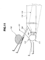
Fig. 11 , when atreatment instrument 100 is led out toward atreatment region 102 in a stomach through astomach wall 101, the operator first tilts anendoscope insertion portion 110 as indicated by a broken line and, in this state, brings atransducer lens surface 112 of anultrasound transducer 111 into close contact with thestomach wall 101. Then, while keeping the close-contact state, the operator manipulates thetreatment instrument 100 so as to be led in toward thetreatment region 102. In this case, the insertion direction, i.e. the pressing direction, of theendoscope insertion portion 110 will be as indicated by a broken arrow A, and the lead-out direction of thetreatment instrument 100 will be as indicated by a broken arrow B. - Accordingly, when the
treatment instrument 100 is projected from theendoscope insertion portion 110, theendoscope insertion portion 110 may be displaced as indicated by the solid line because the lead-out direction and the insertion direction are not identical. Then, the insertion direction of theendoscope insertion portion 110 may probably be changed in the direction indicated by a solid arrow C, resulting in a possible change of the lead-out direction of thetreatment instrument 100 in the direction indicated by a solid arrow D. In this case, the lead-out direction of thetreatment instrument 100 is deviated from thetreatment region 102, bringing difficulty in conducting desired treatment. - Meanwhile, in the ultrasound endoscope of Japanese Patent Application Laid-Open Publication No.
8-131442 - The present invention has been made in light of the circumstances as described above, and has an object of providing an ultrasound endoscope which enables forward optical observation along the insertion direction of the insertion portion, and can reliably lead out a treatment instrument toward a target region of a deep portion forward along the insertion direction, which target region is visualized in the ultrasound image.
- In addition, the present invention has another object of providing an ultrasound endoscope which well enables observation through an observation optical system, as well as observation through ultrasound image obtained by an ultrasound transducer portion.
- An ultrasound endoscope of the present invention has an insertion portion to be inserted into a body cavity, the insertion portion comprising at a distal end thereof: a distal rigid portion arranged forward of a flexible tube portion; an ultrasound transducer portion for scanning a plane which is parallel to forward side of a longitudinal center axis of the distal rigid portion; and a treatment instrument insertion channel port opening in a distal-side end face of the distal rigid portion, the port having a longitudinal center axis which is parallel to the longitudinal center axis of the distal rigid portion.
- The ultrasound endoscope of the present invention has a distal rigid portion configuring an insertion portion to be inserted into a body cavity and arranged forward of a flexible tube portion, the ultrasound endoscope comprising at the distal rigid portion thereof: an ultrasound transducer portion for scanning a plane which is parallel to forward side of a longitudinal center axis of the distal rigid portion; and a treatment instrument insertion channel port configuring an instrument channel for leading out a treatment instrument with respect to a scanning plane forward of the ultrasound transducer portion, the port having a longitudinal center axis which is parallel to the longitudinal center axis of the distal rigid portion, wherein:
- a distal end surface of a distal rigid portion comprises an observation window configuring an observation optical system, an illumination window configuring an illumination optical system, and an air/water supply nozzle for ejecting fluid at least to a surface of the observation window; the air/water supply nozzle is arranged outside an ultrasound observation region possessed by the ultrasound transducer portion; the observation window is arranged at a position outside the ultrasound observation region possessed by the ultrasound transducer portion, the position corresponding to a position where the ultrasound transducer portion is permitted to fall outside an observation field of view of the observation optical system; and the illumination window is arranged at a position outside the ultrasound observation region possessed by the ultrasound transducer portion, the position corresponding to a position on a more outer peripheral side than the observation window.
-
-
Fig. 1 is an illustration explaining a configuration of an ultrasound endoscope; -
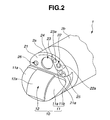
Fig. 2 is a perspective view illustrating a distal end portion of an ultrasound endoscope; -
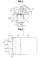
Fig. 3 is a front elevational view of the distal end portion illustrated inFig. 2 , as viewed from the front; -
Fig. 4 is a top view of the distal end portion illustrated inFig. 2 , as viewed from the top; -
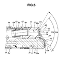
Fig. 5 is a cross-sectional view taken along a line A-A ofFig. 3 ; -
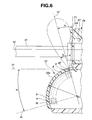
Fig. 6 is an illustration explaining a relationship between: an ultrasound transducer configured by arranging a plurality of piezoelectric elements; and an ultrasound observation region of the ultrasound transducer and a treatment instrument led out from an instrument channel; -
Fig. 7 is an illustration indicating an example of an ultrasound image including an artifact as appeared; -
Fig. 8 is an illustration indicating an example of an ultrasound image visualized by the ultrasound transducer illustrated inFig. 6 ; -
Fig. 9 is an illustration explaining a relationship between a tissue contact surface of a nose piece and a transducer lens surface of an ultrasound transducer; -
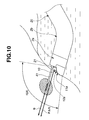
Fig. 10 is an illustration explaining an operation of an ultrasound endoscope; and -
Fig. 11 is an illustration explaining a state where a treatment instrument is led into a treatment region through a stomach wall, using a conventional ultrasound endoscope. - With reference to the drawings, an embodiment of the present invention will hereinafter be described in detail.
- With reference to
Figs. 1 to 10 , the embodiment of the present invention will be described in detail. - As shown in
Fig. 1 , anultrasound endoscope 1 of the present embodiment is configured by being provided with anelongated insertion portion 2 to be inserted into a body cavity, anoperation portion 3 provided at a proximal end of theinsertion portion 2, and auniversal cord 4 extending from a side portion of theoperation portion 3. Anendoscope connector 5 is provided at the proximal end portion of theuniversal cord 4. Anultrasound cable 6 is extended from a side portion of theendoscope connector 5. Anultrasound connector 7 is provided at the proximal end portion of theultrasound cable 6. - The
insertion portion 2 is configured by sequentially connecting, from the distal end side, a distalrigid portion 2a formed of a rigid member, abending portion 2b configured so as to be bendable, and an elongatedflexible tube portion 2c having flexibility and extending from the proximal end of thebending portion 2b to the distal end of theoperation portion 3. Indicated byreference 10 is an ultrasound transducer portion provided with a convex-type ultrasound transducer that will be described later. Theultrasound transducer 10 forms anultrasound observation region 10A for scanning in a forward direction along an insertion axial direction. In other words, theultrasound transducer portion 10 has theultrasound observation region 10A for scanning in a forward direction. - The
operation portion 3 is provided with anangle knob 3a for performing bending operation. Theoperation portion 3 is also provided with an air/water supply button 3b for performing operation of air/water supply and asuction button 3c for performing suction. Theoperation portion 3 is further provided with a treatmentinstrument insertion port 3d for introducing a treatment instrument into a body cavity. - As shown in
Fig. 2 , the distalrigid portion 2a of theinsertion portion 2 is provided with theultrasound transducer portion 10 for obtaining ultrasound acoustic image information. Theultrasound transducer portion 10 is configured by being provided with anose piece 11 serving as a housing and anultrasound transducer 12. Theultrasound transducer 12 is arranged for integration at a notch portion which is formed substantially at the center of thenose piece 11. - A
tissue contact surface 11a and atransducer lens surface 12a of theultrasound transducer 12, which configure thenose piece 11, are configured being projected from adistal end surface 21 of the distalrigid portion 2a. - The
distal end surface 21 of the distalrigid portion 2a is provided with anobservation window 22a configuring an observationoptical system 22, anillumination window 23a configuring an illuminationoptical system 23, an instrument channel (hereinafter shortened as a lead-out port) 24 for leading out a treatment instrument, such as a puncture needle, an air/water supply nozzle 25 for ejecting fluid, such as water and air, toward theobservation window 22a, and an auxiliary watersupply channel port 26 for supplying water in the forward direction. - As shown in
Fig. 3 , in theultrasound endoscope 1 according to the present embodiment, thedistal end surface 21 is divided into a section for endoscopic observation, which is the upper side of a horizontal line H passing a longitudinal center axis L1 of the distalrigid portion 2a, and a section for ultrasound observation, which is the lower side. - It is so configured that a vertical center line L2 of the lead-out
port 24 is substantially aligned with a vertical center line L3 of thetransducer lens surface 12a of theultrasound transducer 12. - The radial dimension of the lead-out
port 24 is formed to have a size that falls within a width dimension W of anultrasound observation region 10A formed by the ultrasound emitted from thetransducer lens surface 12a, which area is indicated by a dash-dot-dot line. As a result, a treatment instrument led out from the lead-outport 24 reliably moves within theultrasound observation region 10A. - The
observation window 22a, theillumination window 23a and the air/water supply nozzle 25 are collectively arranged on one side which corresponds, for example, to the right side of the figure, with respect to the lead-outport 24. Also, theobservation window 22a, theillumination window 23a and the air/water supply nozzle 25 are arranged outside theultrasound observation region 10A. - Among the
observation window 22a, theillumination window 23a and the air/water supply nozzle 25, the arrangement position of the air/water supply nozzle 25 is set so as to be located farthest from theultrasound observation region 10A. This is because, as shown inFig. 4 , the air/water supply nozzle 25 is provided, being projected with respect to thedistal end surface 21 of the distalrigid portion 2a. Specifically, the arrangement of the projected air/water supply nozzle 25 close to theultrasound observation region 10A may cause the ultrasound emitted from thetransducer lens surface 12a to be reflected by the air/water supply nozzle 25 to visualize the air/water supply nozzle in the ultrasound image. The farthest positioning is purposed for preventing such visualization. - In the present embodiment, the
illumination window 23a, theobservation window 22a and the air/water supply nozzle 25 are positioned so as to be aligned with each other, considering the objects of improving observation performance, of improving cleaning performance and of reducing the outer radial dimension of the distal end portion of the endoscope. - The
observation window 22a is positioned being distanced from theultrasound transducer portion 10, that is, positioned at an upper position in the figure, considering the observation field of view of the observationoptical system 22, which will be described later, refer to the range ofreference 22A indicated by a dash-dot line inFig. 5 . This may eliminate the drawback, i.e. partial lack of an endoscopic image displayed on a screen of a display device, not shown, which drawback would be caused by the blocking of the observation field of view by theultrasound transducer portion 10 during the endoscopic observation. - On the other hand, the
illumination window 23a is positioned being distanced from theultrasound transducer portion 10, that is, positioned at an upper position on a more outer peripheral side than theobservation window 22a, considering the radiation range of the illumination light from the illuminationoptical system 23, refer to the range ofreference 23A indicated by a dash-dot-dot line inFig. 5 . This may eliminate the drawback, i.e. visualization of theultrasound transducer portion 10 in the observation image during the endoscopic observation. - The
observation window 22a and theillumination window 23a are provided in an observationdistal end surface 21a which is configured to slightly project from thedistal end surface 21. The auxiliary watersupply channel port 26 is located on the other side, or the opposite side, of the side on which theobservation window 22a, theillumination window 23a and the air/water supply nozzle 25 are arranged, the other side being the outside of theultrasound observation region 10A. - As shown in
Fig. 5 , adistal bending piece 8a configuring the bendingportion 2b is connected and fixed to the proximal end side of the distalrigid portion 2a. A plurality of bending pieces are sequentially connected to thedistal bending piece 8a. Distal end portions of respective up-and-down and left-and-right bending wires 8w are fixedly set at predetermined positions of thedistal bending piece 8a. Thus, with an operator's appropriate manipulation of theangle knob 3a, therelevant bending wires 8w are adapted to be tugged and released in response to the manipulation, so that bending motion can be imparted to the bendingportion 2b can be bent. - The plurality of bending pieces are covered with bending
rubber 8g. The distal end portion of the bendingrubber 8g is integrally fixed to the distalrigid portion 2a by a bobbin bondedportion 8h. - The
distal end surface 21 of the distalrigid portion 2a and the observationdistal end surface 21a are configured so as to be orthogonal to the longitudinal center axis L1 of the distalrigid portion 2a. The distalrigid portion 2a is formed with a treatment instrument insertion channel port (hereinafter shortened as treatment instrument hole) 27 configuring theinstrument channel 24, and also formed with anarrangement hole 30. - In addition to the
holes rigid portion 2a is also provided, although not shown, with a through hole for setting the observation optical system, a through hole for setting the illumination optical system, an air/water supply through hole for supplying the fluid ejected from the air/water supply nozzle 25, a through hole configuring the auxiliary watersupply channel port 26, and the like. - A longitudinal center axis L4 of the
treatment instrument hole 27 is formed to be substantially parallel to the longitudinal center axis L1 of the distalrigid portion 2a. A longitudinal center axis L5 of thearrangement hole 30 is formed to be substantially parallel to the longitudinal center axis L1 of the distalrigid portion 2a. Optical axes L6 and L7 of the observation optical system and the illumination optical system, respectively, provided in theultrasound endoscope 1 are also parallel to the longitudinal center axis L1 of the distalrigid portion 2a. Accordingly, the observation optical system provided in theultrasound endoscope 1 of the present embodiment is of a so-called forward viewing type, in which the observation field of view is set at a forward front, that is, the observation field of view is set in the insertion direction, or is set forward along the longitudinal center axis L1 of the distalrigid portion 2a. - One end portion of a
tube linking pipe 28 which is formed being inclined by a predetermined amount, is permitted to communicate with the proximal end side of thetreatment instrument hole 27. One end portion of achannel tube 29 configuring a channel for inserting treatment instrument is permitted to communicate with the other end portion of thetube linking pipe 28. The other end portion of thechannel tube 29 is permitted to communicate with the treatmentinstrument insertion port 3d. - Thus, a treatment instrument inserted through the treatment
instrument insertion port 3d is smoothly moved through thechannel tube 29, thetube linking pipe 28 and thetreatment instrument hole 27, so as to be led out of theinstrument channel 24 to the outside. The treatment instrument that has been led out of theinstrument channel 24 is projected forward, or projected along the insertion direction for the insertion portion, being substantially parallel to the longitudinal center axis L1 of the distalrigid portion 2a. - Specifically, let us assume that the distal end portion of a puncture needle, as a treatment instrument, for example, is located in the
treatment instrument hole 27. In this state, upon projection of a needle tube configuring the puncture needle, the needle tube is projected from theinstrument channel 24 toward the forward front which is under observation through theobservation window 22a, while being substantially parallel to the longitudinal center axis L1 of the distalrigid portion 2a. - A fixing portion of the
nose piece 11 is arranged in thearrangement hole 30, refer to reference 11c ofFig. 9 which will be described later. A distal end portion of an insulating tube, not shown, is fixedly permitted to communicate with the proximal end portion of the fixingportion 11c. Anultrasound cable 34 is inserted through the insulating tube. Theultrasound cable 34 is a bunch of a plurality of signal lines extended from a plurality of respective piezoelectric elements configuring theultrasound transducer 12. The insulating tube extends through theinsertion portion 2 so that the other end portion of the insulating tube reaches theoperation portion 3. Theultrasound cable 34 extends through theinsertion portion 2, theoperation portion 3, theuniversal cord 4, theendoscope connector 5 and theultrasound cable 6 to reach theultrasound connector 7. - As shown in
Figs. 5 and6 , theultrasound transducer 12 of theultrasound transducer portion 10 is provided at the center portion of thetissue contact portion 11b of thenose piece 11. Theultrasound transducer 12 is configured, for example, by a plurality ofpiezoelectric elements 9 and thetransducer lens surface 12a. The plurality ofpiezoelectric elements 9 are arranged to form a projected arc. - As shown in
Fig. 6 , it is so configured that a center O1 of the arc forming the arc of theultrasound transducer 12 which is configured by arranging the plurality ofpiezoelectric elements 9, is positioned on the side more proximal than thedistal end surface 21 of the distalrigid portion 2a. The plurality ofpiezoelectric elements 9 having an arc form are arranged at a predetermined pitch from a firstpiezoelectric element 9F located on one end side, for emitting ultrasound to the vicinity of a projection-starting side, to a lastpiezoelectric element 9L located on the other end side. - The direction of a beam axis LF of the first
piezoelectric element 9F is set so as to incline toward the distal end side by an angle θ1, with respect to thedistal end surface 21 of the distalrigid portion 2a, in particular, with respect to thedistal end surface 21 provided with the lead-outport 24. - In setting the direction of the beam axis LF of the first
piezoelectric element 9F, being inclined by the angle θ1, a beam spread angle θ2 of the firstpiezoelectric element 9F is taken into consideration. Specifically, the angle θ1 is set so that at least a portion of the distalrigid portion 2a or at least a portion of the air/water supply nozzle 25, which is made of a material, such as metal or rigid resin, that can reflect ultrasound, for example, will not come into the beam spread angle enclosed by the dash-dot-dot line in the figure. The angle θ1 is set so as to at least exceed θ/2, i.e. one half of the beam spread angle θ2. - If the distal
rigid portion 2a is present within the beam spread angle, anartifact 42 as shown inFig. 7 appears. However, according to the configuration of the present application, no artifact appears, and atreatment instrument image 41 a is clearly visualized in anultrasound image 40, as shown inFig. 8 . Thus, atreatment instrument 41 can be precisely led toward alesion portion 43. - On the other hand, the direction of a beam axis LL of the last
piezoelectric element 9L is set so as to be parallel to the longitudinal center axis L1 of the distalrigid portion 2a, or to be widened toward forward by an angle θ3. - As a result of such setting, when the
treatment instrument 41 projected from theinstrument channel 24 is projected forward substantially parallel to the longitudinalcenter axis L 1 of the distalrigid portion 2a, thetreatment instrument 41 keeps moving within theultrasound observation region 10A. Accordingly, as shown inFig. 8 , thetreatment instrument image 41a is clearly visualized in theultrasound image 40 from the state where thetreatment instrument 41 is slightly projected from theinstrument channel 24 to the point when thetreatment instrument 41 punctures thelesion portion 43. - As shown in
Figs. 2 ,4 ,5 and9 , thenose piece 11 has thetissue contact portion 11b and the fixingportion 11c. Thetissue contact portion 11b has thetissue contact surface 11a of an arc form. The fixingportion 11c is arranged in thearrangement hole 30. The proximal end surface of thetissue contact portion 11b is abutting surface 11d, which is arranged being in contact with aplanar surface portion 36a of astep portion 36. Theplanar surface portion 36a is provided with an opening, not shown, of thearrangement hole 30. - The outer radial dimension of a portion extending from the side of the
butting surface 11d to the distal end of thenose piece 11 is set so as to have substantially the same dimension as the distal outer radial dimension of the distalrigid portion 2a, as shown inFigs. 2 to 4 . Thus, the rigidity can be enhanced in thetissue contact portion 11b which is provided with thetissue contact surface 11a. In other words, the strength of thetissue contact portion 11b of thenose piece 11 is increased to achieve steady butting. - As shown in
Fig. 9 , the dimension of an arc radius r1 of thetissue contact surface 11a provided at thenose piece 11 is set to be the same as or slightly smaller than an arc radius r2 of thetransducer lens surface 12a configuring theultrasound transducer 12 and indicated by the dash-dot-dot line. A center O2 of the arc of thetissue contact surface 11a and the center O1 of the arc of thetransducer lens surface 12a are set to be positioned on an axis parallel to the horizontal line H. - As described above, the
transducer lens surface 12a of theultrasound transducer 12 and thetissue contact surface 11a of thetissue contact portion 11b which is provided being interposed by theultrasound transducer 12, are configured to substantially coincide with each other. - With such a configuration, when the
ultrasound transducer portion 10 is pressed against body tissues for ultrasound observation, thetissue contact surface 11a and thetransducer lens surface 12a are substantially uniformly brought into close contact with the body tissues. Thus, theultrasound transducer portion 10 can be steadily pressed against the body tissues to obtain an ultrasound observation image. - Also, in performing puncture using a treatment instrument under ultrasound observation, coincidence is attained between: the insertion direction of the
insertion portion 2, which substantially goes along with the longitudinal center axis L1 of the distalrigid portion 2a and is indicated by an arrow P; and the puncture direction of thetreatment instrument 41, which is indicated by an arrow Q, as shown inFig. 10 . As a result, upon operator's lead-in manipulation of thetreatment instrument 41, a force associated with thetreatment instrument 41 can be efficiently converted into a lead-in force to enhance the lead-in properties and the puncture properties of thetreatment instrument 41. - It should be appreciated that the present invention is not limited only to the embodiment described above, but various modifications may be available within a scope not departing from the spirit of the invention.
- The present application is filed claiming priority from Japanese Patent Application No.
2006-58708
Claims (7)
- An ultrasound endoscope having an insertion portion to be inserted into a body cavity, the insertion portion comprising at a distal end thereof:a distal rigid portion arranged forward of a flexible tube portion;an ultrasound transducer portion for scanning a plane which is parallel to forward side of a longitudinal center axis of the distal rigid portion; anda treatment instrument insertion channel port opening in a distal-side end face of the distal rigid portion, the port having a longitudinal center axis which is parallel to the longitudinal center axis of the distal rigid portion.
- The ultrasound endoscope according to claim 1, wherein
the distal end of the insertion portion further comprises an observation optical system having an optical axis which is parallel to the longitudinal center axis of the distal rigid portion. - The ultrasound endoscope according to claim 1, wherein
the ultrasound transducer portion comprises a nose piece serving as a housing and an ultrasound transducer in which piezoelectric elements are arranged; and
the nose piece comprises: a tissue contact portion which is projected from the distal end surface of the distal rigid portion and has a tissue contact surface configured to coincide with the transducer lens surface; and a fixing portion which is fixed to the distal rigid portion. - The ultrasound endoscope according to claim 1, wherein
the nose piece has as fixing portion whose outer radial dimension on a proximal end side is set so as to be approximate to a distal-end outer radius of the distal rigid portion. - An ultrasound endoscope having a distal rigid portion configuring an insertion portion to be inserted into a body cavity and arranged forward of a flexible tube portion, the ultrasound endoscope comprising at the distal rigid portion thereof: an ultrasound transducer portion for scanning a plane which is parallel to forward side of a longitudinal center axis of the distal rigid portion; and a treatment instrument insertion channel port configuring an instrument channel for leading out a treatment instrument with respect to a scanning plane forward of the ultrasound transducer portion, the port having a longitudinal center axis which is parallel to the longitudinal center axis of the distal rigid portion, wherein
a distal end surface of a distal rigid portion comprises an observation window configuring an observation optical system, an illumination window configuring an illumination optical system, and an air/water supply nozzle for ejecting fluid at least to a surface of the observation window;
the air/water supply nozzle is arranged outside an ultrasound observation region possessed by the ultrasound transducer portion;
the observation window is arranged at a position outside the ultrasound observation region possessed by the ultrasound transducer portion, the position corresponding to a position where the ultrasound transducer portion is permitted to fall outside an observation field of view of the observation optical system; and
the illumination window is arranged at a position outside the ultrasound observation region possessed by the ultrasound transducer portion, the position corresponding to a position on a more outer peripheral side than the observation window. - The ultrasound endoscope according to claim 5, wherein
among the observation window, the illumination window and the air/water supply nozzle, the air/water supply nozzle is arranged at a position which is farthest from the ultrasound scanning plane. - The ultrasound endoscope according to claim 5 or 6, wherein
the observation window, the illumination window and the air/water supply nozzle are positioned so as to be substantially aligned with each other.
Applications Claiming Priority (2)
| Application Number | Priority Date | Filing Date | Title |
|---|---|---|---|
| JP2006058708A JP2007236414A (en) | 2006-03-03 | 2006-03-03 | Ultrasonic endoscope |
| PCT/JP2007/053928 WO2007100050A1 (en) | 2006-03-03 | 2007-03-01 | Ultrasonic endoscope |
Publications (2)
| Publication Number | Publication Date |
|---|---|
| EP1992292A1 true EP1992292A1 (en) | 2008-11-19 |
| EP1992292A4 EP1992292A4 (en) | 2013-08-28 |
Family
ID=38459149
Family Applications (1)
| Application Number | Title | Priority Date | Filing Date |
|---|---|---|---|
| EP07737608.5A Withdrawn EP1992292A4 (en) | 2006-03-03 | 2007-03-01 | Ultrasonic endoscope |
Country Status (5)
| Country | Link |
|---|---|
| US (1) | US20090005689A1 (en) |
| EP (1) | EP1992292A4 (en) |
| JP (1) | JP2007236414A (en) |
| CN (1) | CN101394792B (en) |
| WO (1) | WO2007100050A1 (en) |
Cited By (30)
| Publication number | Priority date | Publication date | Assignee | Title |
|---|---|---|---|---|
| US8926502B2 (en) | 2011-03-07 | 2015-01-06 | Endochoice, Inc. | Multi camera endoscope having a side service channel |
| EP2671513A4 (en) * | 2011-10-27 | 2015-05-20 | Olympus Medical Systems Corp | Ultrasonic observation device |
| US9101266B2 (en) | 2011-02-07 | 2015-08-11 | Endochoice Innovation Center Ltd. | Multi-element cover for a multi-camera endoscope |
| US9101268B2 (en) | 2009-06-18 | 2015-08-11 | Endochoice Innovation Center Ltd. | Multi-camera endoscope |
| US9101287B2 (en) | 2011-03-07 | 2015-08-11 | Endochoice Innovation Center Ltd. | Multi camera endoscope assembly having multiple working channels |
| US9314147B2 (en) | 2011-12-13 | 2016-04-19 | Endochoice Innovation Center Ltd. | Rotatable connector for an endoscope |
| US9320419B2 (en) | 2010-12-09 | 2016-04-26 | Endochoice Innovation Center Ltd. | Fluid channeling component of a multi-camera endoscope |
| US9402533B2 (en) | 2011-03-07 | 2016-08-02 | Endochoice Innovation Center Ltd. | Endoscope circuit board assembly |
| US9492063B2 (en) | 2009-06-18 | 2016-11-15 | Endochoice Innovation Center Ltd. | Multi-viewing element endoscope |
| US9554692B2 (en) | 2009-06-18 | 2017-01-31 | EndoChoice Innovation Ctr. Ltd. | Multi-camera endoscope |
| US9560954B2 (en) | 2012-07-24 | 2017-02-07 | Endochoice, Inc. | Connector for use with endoscope |
| US9560953B2 (en) | 2010-09-20 | 2017-02-07 | Endochoice, Inc. | Operational interface in a multi-viewing element endoscope |
| US9642513B2 (en) | 2009-06-18 | 2017-05-09 | Endochoice Inc. | Compact multi-viewing element endoscope system |
| US9655502B2 (en) | 2011-12-13 | 2017-05-23 | EndoChoice Innovation Center, Ltd. | Removable tip endoscope |
| US9706903B2 (en) | 2009-06-18 | 2017-07-18 | Endochoice, Inc. | Multiple viewing elements endoscope system with modular imaging units |
| US9713417B2 (en) | 2009-06-18 | 2017-07-25 | Endochoice, Inc. | Image capture assembly for use in a multi-viewing elements endoscope |
| US9814374B2 (en) | 2010-12-09 | 2017-11-14 | Endochoice Innovation Center Ltd. | Flexible electronic circuit board for a multi-camera endoscope |
| US9872609B2 (en) | 2009-06-18 | 2018-01-23 | Endochoice Innovation Center Ltd. | Multi-camera endoscope |
| US9901244B2 (en) | 2009-06-18 | 2018-02-27 | Endochoice, Inc. | Circuit board assembly of a multiple viewing elements endoscope |
| US9986899B2 (en) | 2013-03-28 | 2018-06-05 | Endochoice, Inc. | Manifold for a multiple viewing elements endoscope |
| US9993142B2 (en) | 2013-03-28 | 2018-06-12 | Endochoice, Inc. | Fluid distribution device for a multiple viewing elements endoscope |
| US10080486B2 (en) | 2010-09-20 | 2018-09-25 | Endochoice Innovation Center Ltd. | Multi-camera endoscope having fluid channels |
| US10165929B2 (en) | 2009-06-18 | 2019-01-01 | Endochoice, Inc. | Compact multi-viewing element endoscope system |
| US10203493B2 (en) | 2010-10-28 | 2019-02-12 | Endochoice Innovation Center Ltd. | Optical systems for multi-sensor endoscopes |
| US10499794B2 (en) | 2013-05-09 | 2019-12-10 | Endochoice, Inc. | Operational interface in a multi-viewing element endoscope |
| EP3603529A4 (en) * | 2017-03-31 | 2020-04-01 | FUJIFILM Corporation | Ultrasonic endoscope |
| US11278190B2 (en) | 2009-06-18 | 2022-03-22 | Endochoice, Inc. | Multi-viewing element endoscope |
| US11547275B2 (en) | 2009-06-18 | 2023-01-10 | Endochoice, Inc. | Compact multi-viewing element endoscope system |
| US11864734B2 (en) | 2009-06-18 | 2024-01-09 | Endochoice, Inc. | Multi-camera endoscope |
| US11889986B2 (en) | 2010-12-09 | 2024-02-06 | Endochoice, Inc. | Flexible electronic circuit board for a multi-camera endoscope |
Families Citing this family (7)
| Publication number | Priority date | Publication date | Assignee | Title |
|---|---|---|---|---|
| US20090287080A1 (en) | 2008-05-15 | 2009-11-19 | Olympus Medical Systems Corp. | Treatment instrument for endoscope and lymph node removing method |
| CN101803905A (en) * | 2010-03-16 | 2010-08-18 | 广州市番禺区胆囊病研究所 | Integrated rigid ultrasonic arthroscope system |
| JP2014018282A (en) * | 2012-07-13 | 2014-02-03 | Olympus Medical Systems Corp | Ultrasonic endoscope |
| WO2014038638A1 (en) * | 2012-09-05 | 2014-03-13 | オリンパスメディカルシステムズ株式会社 | Ultrasonic endoscope |
| WO2018003180A1 (en) | 2016-06-29 | 2018-01-04 | オリンパス株式会社 | Ultrasonic endoscope |
| CN109715073A (en) * | 2016-09-15 | 2019-05-03 | 奥林巴斯株式会社 | Ultrasonic endoscope and ultrasonic endoscope system |
| US10925628B2 (en) | 2017-09-18 | 2021-02-23 | Novuson Surgical, Inc. | Tissue engagement apparatus for theapeutic ultrasound apparatus and method |
Citations (4)
| Publication number | Priority date | Publication date | Assignee | Title |
|---|---|---|---|---|
| JPH0984791A (en) * | 1995-09-25 | 1997-03-31 | Fuji Photo Optical Co Ltd | Ultrasonic endoscope |
| US6149598A (en) * | 1998-03-31 | 2000-11-21 | Fuji Photo Optical Co., Ltd. | Ultrasound endoscope |
| JP2001212146A (en) * | 2000-02-04 | 2001-08-07 | Fuji Photo Optical Co Ltd | Intra-corporeal ultrasonic inspecting device |
| JP2004350700A (en) * | 2003-05-26 | 2004-12-16 | Olympus Corp | Ultrasonic endoscope apparatus |
Family Cites Families (15)
| Publication number | Priority date | Publication date | Assignee | Title |
|---|---|---|---|---|
| AUPM413594A0 (en) * | 1994-02-28 | 1994-03-24 | Psk Connectors Pty. Ltd. | Endoscope cleaning system |
| JP3441532B2 (en) * | 1994-11-01 | 2003-09-02 | ペンタックス株式会社 | Ultrasound endoscope tip |
| JPH08131442A (en) | 1994-11-04 | 1996-05-28 | Olympus Optical Co Ltd | Ultrasonic endoscope |
| JP3198903B2 (en) * | 1995-11-24 | 2001-08-13 | 富士写真光機株式会社 | Ultrasound diagnostic equipment |
| JP3594278B2 (en) * | 1996-10-17 | 2004-11-24 | オリンパス株式会社 | Intracavity ultrasonic probe device |
| US5938612A (en) * | 1997-05-05 | 1999-08-17 | Creare Inc. | Multilayer ultrasonic transducer array including very thin layer of transducer elements |
| JPH11137555A (en) * | 1997-11-10 | 1999-05-25 | Olympus Optical Co Ltd | Ultrasonic diagnostic apparatus |
| JP3331177B2 (en) * | 1998-07-29 | 2002-10-07 | 旭光学工業株式会社 | Sector scan ultrasound probe |
| JP3561643B2 (en) * | 1998-11-12 | 2004-09-02 | 日本電波工業株式会社 | Ultrasonic probe |
| JP3671764B2 (en) * | 1999-09-24 | 2005-07-13 | フジノン株式会社 | Endoscope removable electronic scanning ultrasonic inspection system |
| US6461304B1 (en) * | 1999-03-30 | 2002-10-08 | Fuji Photo Optical Co., Ltd. | Ultrasound inspection apparatus detachably connected to endoscope |
| JP3671763B2 (en) * | 1999-09-22 | 2005-07-13 | フジノン株式会社 | Endoscope removable ultrasound system |
| JP2005168770A (en) * | 2003-12-10 | 2005-06-30 | Olympus Corp | Endoscope |
| JP4618410B2 (en) * | 2004-07-06 | 2011-01-26 | 富士フイルム株式会社 | Ultrasound endoscope |
| JP4586456B2 (en) | 2004-08-20 | 2010-11-24 | 富士ゼロックス株式会社 | Toner supply device and image forming apparatus |
-
2006
- 2006-03-03 JP JP2006058708A patent/JP2007236414A/en active Pending
-
2007
- 2007-03-01 EP EP07737608.5A patent/EP1992292A4/en not_active Withdrawn
- 2007-03-01 CN CN2007800072633A patent/CN101394792B/en active Active
- 2007-03-01 WO PCT/JP2007/053928 patent/WO2007100050A1/en active Application Filing
-
2008
- 2008-09-03 US US12/203,663 patent/US20090005689A1/en not_active Abandoned
Patent Citations (4)
| Publication number | Priority date | Publication date | Assignee | Title |
|---|---|---|---|---|
| JPH0984791A (en) * | 1995-09-25 | 1997-03-31 | Fuji Photo Optical Co Ltd | Ultrasonic endoscope |
| US6149598A (en) * | 1998-03-31 | 2000-11-21 | Fuji Photo Optical Co., Ltd. | Ultrasound endoscope |
| JP2001212146A (en) * | 2000-02-04 | 2001-08-07 | Fuji Photo Optical Co Ltd | Intra-corporeal ultrasonic inspecting device |
| JP2004350700A (en) * | 2003-05-26 | 2004-12-16 | Olympus Corp | Ultrasonic endoscope apparatus |
Non-Patent Citations (1)
| Title |
|---|
| See also references of WO2007100050A1 * |
Cited By (57)
| Publication number | Priority date | Publication date | Assignee | Title |
|---|---|---|---|---|
| US10165929B2 (en) | 2009-06-18 | 2019-01-01 | Endochoice, Inc. | Compact multi-viewing element endoscope system |
| US9642513B2 (en) | 2009-06-18 | 2017-05-09 | Endochoice Inc. | Compact multi-viewing element endoscope system |
| US11864734B2 (en) | 2009-06-18 | 2024-01-09 | Endochoice, Inc. | Multi-camera endoscope |
| US9101268B2 (en) | 2009-06-18 | 2015-08-11 | Endochoice Innovation Center Ltd. | Multi-camera endoscope |
| US11547275B2 (en) | 2009-06-18 | 2023-01-10 | Endochoice, Inc. | Compact multi-viewing element endoscope system |
| US10092167B2 (en) | 2009-06-18 | 2018-10-09 | Endochoice, Inc. | Multiple viewing elements endoscope system with modular imaging units |
| US11534056B2 (en) | 2009-06-18 | 2022-12-27 | Endochoice, Inc. | Multi-camera endoscope |
| US11471028B2 (en) | 2009-06-18 | 2022-10-18 | Endochoice, Inc. | Circuit board assembly of a multiple viewing elements endoscope |
| US11278190B2 (en) | 2009-06-18 | 2022-03-22 | Endochoice, Inc. | Multi-viewing element endoscope |
| US9492063B2 (en) | 2009-06-18 | 2016-11-15 | Endochoice Innovation Center Ltd. | Multi-viewing element endoscope |
| US9554692B2 (en) | 2009-06-18 | 2017-01-31 | EndoChoice Innovation Ctr. Ltd. | Multi-camera endoscope |
| US10912445B2 (en) | 2009-06-18 | 2021-02-09 | Endochoice, Inc. | Compact multi-viewing element endoscope system |
| US9901244B2 (en) | 2009-06-18 | 2018-02-27 | Endochoice, Inc. | Circuit board assembly of a multiple viewing elements endoscope |
| US9872609B2 (en) | 2009-06-18 | 2018-01-23 | Endochoice Innovation Center Ltd. | Multi-camera endoscope |
| US10799095B2 (en) | 2009-06-18 | 2020-10-13 | Endochoice, Inc. | Multi-viewing element endoscope |
| US9706905B2 (en) | 2009-06-18 | 2017-07-18 | Endochoice Innovation Center Ltd. | Multi-camera endoscope |
| US9706903B2 (en) | 2009-06-18 | 2017-07-18 | Endochoice, Inc. | Multiple viewing elements endoscope system with modular imaging units |
| US9713417B2 (en) | 2009-06-18 | 2017-07-25 | Endochoice, Inc. | Image capture assembly for use in a multi-viewing elements endoscope |
| US10791909B2 (en) | 2009-06-18 | 2020-10-06 | Endochoice, Inc. | Image capture assembly for use in a multi-viewing elements endoscope |
| US10791910B2 (en) | 2009-06-18 | 2020-10-06 | Endochoice, Inc. | Multiple viewing elements endoscope system with modular imaging units |
| US10638922B2 (en) | 2009-06-18 | 2020-05-05 | Endochoice, Inc. | Multi-camera endoscope |
| US10080486B2 (en) | 2010-09-20 | 2018-09-25 | Endochoice Innovation Center Ltd. | Multi-camera endoscope having fluid channels |
| US9560953B2 (en) | 2010-09-20 | 2017-02-07 | Endochoice, Inc. | Operational interface in a multi-viewing element endoscope |
| US9986892B2 (en) | 2010-09-20 | 2018-06-05 | Endochoice, Inc. | Operational interface in a multi-viewing element endoscope |
| US10203493B2 (en) | 2010-10-28 | 2019-02-12 | Endochoice Innovation Center Ltd. | Optical systems for multi-sensor endoscopes |
| US11543646B2 (en) | 2010-10-28 | 2023-01-03 | Endochoice, Inc. | Optical systems for multi-sensor endoscopes |
| US9320419B2 (en) | 2010-12-09 | 2016-04-26 | Endochoice Innovation Center Ltd. | Fluid channeling component of a multi-camera endoscope |
| US10182707B2 (en) | 2010-12-09 | 2019-01-22 | Endochoice Innovation Center Ltd. | Fluid channeling component of a multi-camera endoscope |
| US11889986B2 (en) | 2010-12-09 | 2024-02-06 | Endochoice, Inc. | Flexible electronic circuit board for a multi-camera endoscope |
| US9814374B2 (en) | 2010-12-09 | 2017-11-14 | Endochoice Innovation Center Ltd. | Flexible electronic circuit board for a multi-camera endoscope |
| US11497388B2 (en) | 2010-12-09 | 2022-11-15 | Endochoice, Inc. | Flexible electronic circuit board for a multi-camera endoscope |
| US10898063B2 (en) | 2010-12-09 | 2021-01-26 | Endochoice, Inc. | Flexible electronic circuit board for a multi camera endoscope |
| US9351629B2 (en) | 2011-02-07 | 2016-05-31 | Endochoice Innovation Center Ltd. | Multi-element cover for a multi-camera endoscope |
| US9101266B2 (en) | 2011-02-07 | 2015-08-11 | Endochoice Innovation Center Ltd. | Multi-element cover for a multi-camera endoscope |
| US10070774B2 (en) | 2011-02-07 | 2018-09-11 | Endochoice Innovation Center Ltd. | Multi-element cover for a multi-camera endoscope |
| US10292578B2 (en) | 2011-03-07 | 2019-05-21 | Endochoice Innovation Center Ltd. | Multi camera endoscope assembly having multiple working channels |
| US9854959B2 (en) | 2011-03-07 | 2018-01-02 | Endochoice Innovation Center Ltd. | Multi camera endoscope assembly having multiple working channels |
| US9713415B2 (en) | 2011-03-07 | 2017-07-25 | Endochoice Innovation Center Ltd. | Multi camera endoscope having a side service channel |
| US9101287B2 (en) | 2011-03-07 | 2015-08-11 | Endochoice Innovation Center Ltd. | Multi camera endoscope assembly having multiple working channels |
| US8926502B2 (en) | 2011-03-07 | 2015-01-06 | Endochoice, Inc. | Multi camera endoscope having a side service channel |
| US11026566B2 (en) | 2011-03-07 | 2021-06-08 | Endochoice, Inc. | Multi camera endoscope assembly having multiple working channels |
| US9402533B2 (en) | 2011-03-07 | 2016-08-02 | Endochoice Innovation Center Ltd. | Endoscope circuit board assembly |
| EP2671513A4 (en) * | 2011-10-27 | 2015-05-20 | Olympus Medical Systems Corp | Ultrasonic observation device |
| US9314147B2 (en) | 2011-12-13 | 2016-04-19 | Endochoice Innovation Center Ltd. | Rotatable connector for an endoscope |
| US9655502B2 (en) | 2011-12-13 | 2017-05-23 | EndoChoice Innovation Center, Ltd. | Removable tip endoscope |
| US10470649B2 (en) | 2011-12-13 | 2019-11-12 | Endochoice, Inc. | Removable tip endoscope |
| US11291357B2 (en) | 2011-12-13 | 2022-04-05 | Endochoice, Inc. | Removable tip endoscope |
| US9560954B2 (en) | 2012-07-24 | 2017-02-07 | Endochoice, Inc. | Connector for use with endoscope |
| US10905315B2 (en) | 2013-03-28 | 2021-02-02 | Endochoice, Inc. | Manifold for a multiple viewing elements endoscope |
| US10925471B2 (en) | 2013-03-28 | 2021-02-23 | Endochoice, Inc. | Fluid distribution device for a multiple viewing elements endoscope |
| US11793393B2 (en) | 2013-03-28 | 2023-10-24 | Endochoice, Inc. | Manifold for a multiple viewing elements endoscope |
| US9986899B2 (en) | 2013-03-28 | 2018-06-05 | Endochoice, Inc. | Manifold for a multiple viewing elements endoscope |
| US9993142B2 (en) | 2013-03-28 | 2018-06-12 | Endochoice, Inc. | Fluid distribution device for a multiple viewing elements endoscope |
| US11925323B2 (en) | 2013-03-28 | 2024-03-12 | Endochoice, Inc. | Fluid distribution device for a multiple viewing elements endoscope |
| US10499794B2 (en) | 2013-05-09 | 2019-12-10 | Endochoice, Inc. | Operational interface in a multi-viewing element endoscope |
| EP3603529A4 (en) * | 2017-03-31 | 2020-04-01 | FUJIFILM Corporation | Ultrasonic endoscope |
| US11553894B2 (en) | 2017-03-31 | 2023-01-17 | Fujifilm Corporation | Ultrasonic endoscope |
Also Published As
| Publication number | Publication date |
|---|---|
| CN101394792B (en) | 2012-08-08 |
| US20090005689A1 (en) | 2009-01-01 |
| CN101394792A (en) | 2009-03-25 |
| EP1992292A4 (en) | 2013-08-28 |
| WO2007100050A1 (en) | 2007-09-07 |
| JP2007236414A (en) | 2007-09-20 |
Similar Documents
| Publication | Publication Date | Title |
|---|---|---|
| EP1992292A1 (en) | Ultrasonic endoscope | |
| EP1992291B1 (en) | Ultrasonic endoscope | |
| EP2027818B1 (en) | Ultrasound probe and ultrasound endoscope including ultrasound probe | |
| US20050222493A1 (en) | Endoscope | |
| JPH11276422A (en) | Ultrasonic endoscope | |
| US11317786B2 (en) | Endoscope | |
| EP2671514B1 (en) | Ultrasonic endoscope | |
| JP7086015B2 (en) | Endoscopic ultrasound | |
| JP6594151B2 (en) | Ultrasound endoscope | |
| CN111526798B (en) | Endoscope with a lens | |
| JP6653668B2 (en) | Ultrasound endoscope | |
| JP7216183B2 (en) | Endoscope | |
| US20200315575A1 (en) | Ultrasonic endoscope and manufacturing method of ultrasonic endoscope | |
| JP7246539B2 (en) | Endoscope | |
| JP5513589B2 (en) | Ultrasound endoscope | |
| US11696737B2 (en) | Ultrasonic endoscope including treatment-tool erecting base for erecting treatment tool that is led out from opening formed in distal end rigid portion of endoscope insertion section | |
| JP4511224B2 (en) | Ultrasound endoscope | |
| US20230090335A1 (en) | Ultrasonic endoscope | |
| JP5479762B2 (en) | Ultrasound endoscope | |
| JP5400719B2 (en) | Air / liquid feeding device | |
| JPH11239563A (en) | Intraceloh diagnosing tool and tip part cap therefor | |
| JP2013233272A (en) | Ultrasonic endoscope |
Legal Events
| Date | Code | Title | Description |
|---|---|---|---|
| PUAI | Public reference made under article 153(3) epc to a published international application that has entered the european phase |
Free format text: ORIGINAL CODE: 0009012 |
|
| 17P | Request for examination filed |
Effective date: 20080829 |
|
| AK | Designated contracting states |
Kind code of ref document: A1 Designated state(s): DE FR GB |
|
| DAX | Request for extension of the european patent (deleted) | ||
| RBV | Designated contracting states (corrected) |
Designated state(s): DE FR GB |
|
| A4 | Supplementary search report drawn up and despatched |
Effective date: 20130726 |
|
| RIC1 | Information provided on ipc code assigned before grant |
Ipc: A61B 8/12 20060101AFI20130722BHEP Ipc: A61B 1/018 20060101ALI20130722BHEP Ipc: A61B 1/00 20060101ALI20130722BHEP |
|
| STAA | Information on the status of an ep patent application or granted ep patent |
Free format text: STATUS: THE APPLICATION IS DEEMED TO BE WITHDRAWN |
|
| 18D | Application deemed to be withdrawn |
Effective date: 20140225 |