EP1990466A1 - Improved laundry dryer with refreshment operation - Google Patents
Improved laundry dryer with refreshment operation Download PDFInfo
- Publication number
- EP1990466A1 EP1990466A1 EP07108016A EP07108016A EP1990466A1 EP 1990466 A1 EP1990466 A1 EP 1990466A1 EP 07108016 A EP07108016 A EP 07108016A EP 07108016 A EP07108016 A EP 07108016A EP 1990466 A1 EP1990466 A1 EP 1990466A1
- Authority
- EP
- European Patent Office
- Prior art keywords
- valve
- machine according
- drying machine
- filtering
- drying
- Prior art date
- Legal status (The legal status is an assumption and is not a legal conclusion. Google has not performed a legal analysis and makes no representation as to the accuracy of the status listed.)
- Granted
Links
- 238000001035 drying Methods 0.000 claims abstract description 35
- 238000001914 filtration Methods 0.000 claims abstract description 29
- XLYOFNOQVPJJNP-UHFFFAOYSA-N water Substances O XLYOFNOQVPJJNP-UHFFFAOYSA-N 0.000 claims abstract description 10
- 238000009792 diffusion process Methods 0.000 claims abstract description 6
- 239000007788 liquid Substances 0.000 claims abstract description 6
- 239000007921 spray Substances 0.000 claims abstract 2
- 238000010025 steaming Methods 0.000 claims abstract 2
- 230000008878 coupling Effects 0.000 claims 1
- 238000010168 coupling process Methods 0.000 claims 1
- 238000005859 coupling reaction Methods 0.000 claims 1
- 206010040954 Skin wrinkling Diseases 0.000 description 5
- 230000000694 effects Effects 0.000 description 4
- 239000000463 material Substances 0.000 description 4
- 238000000034 method Methods 0.000 description 4
- 238000009833 condensation Methods 0.000 description 3
- 230000005494 condensation Effects 0.000 description 3
- 239000000126 substance Substances 0.000 description 3
- 238000000605 extraction Methods 0.000 description 2
- 238000009825 accumulation Methods 0.000 description 1
- 230000003213 activating effect Effects 0.000 description 1
- 238000000889 atomisation Methods 0.000 description 1
- 238000004140 cleaning Methods 0.000 description 1
- 230000006835 compression Effects 0.000 description 1
- 238000007906 compression Methods 0.000 description 1
- 238000010981 drying operation Methods 0.000 description 1
- 239000012530 fluid Substances 0.000 description 1
- 238000012423 maintenance Methods 0.000 description 1
- 238000004519 manufacturing process Methods 0.000 description 1
- 238000002604 ultrasonography Methods 0.000 description 1
Images


Classifications
-
- D—TEXTILES; PAPER
- D06—TREATMENT OF TEXTILES OR THE LIKE; LAUNDERING; FLEXIBLE MATERIALS NOT OTHERWISE PROVIDED FOR
- D06F—LAUNDERING, DRYING, IRONING, PRESSING OR FOLDING TEXTILE ARTICLES
- D06F58/00—Domestic laundry dryers
- D06F58/20—General details of domestic laundry dryers
- D06F58/203—Laundry conditioning arrangements
-
- D—TEXTILES; PAPER
- D06—TREATMENT OF TEXTILES OR THE LIKE; LAUNDERING; FLEXIBLE MATERIALS NOT OTHERWISE PROVIDED FOR
- D06F—LAUNDERING, DRYING, IRONING, PRESSING OR FOLDING TEXTILE ARTICLES
- D06F58/00—Domestic laundry dryers
- D06F58/20—General details of domestic laundry dryers
- D06F58/22—Lint collecting arrangements
-
- D—TEXTILES; PAPER
- D06—TREATMENT OF TEXTILES OR THE LIKE; LAUNDERING; FLEXIBLE MATERIALS NOT OTHERWISE PROVIDED FOR
- D06F—LAUNDERING, DRYING, IRONING, PRESSING OR FOLDING TEXTILE ARTICLES
- D06F58/00—Domestic laundry dryers
- D06F58/20—General details of domestic laundry dryers
- D06F58/24—Condensing arrangements
Definitions
- the invention refers to an improved type of laundry drying machine, preferably for domestic use, able of implementing refreshing and anti-wrinkling treatment for the laundry load.
- Drying machines which are able of producing a kind of gaseous diffusion of liquid substances and to convey said substances into a drum containing laundry, with the purpose of carrying out a refreshing or anti-wrinkling treatment. Often the substance used for the treatment is simply steam.
- the condensed moisture generated by said drying and condensation process is used to transform it again into a steam flow, or simply into a diffusion of atomized moisture using ultra-sound techniques, to be diffused through said laundry load to obtain the wanted effect of refreshing and anti-wrinkling.
- the water which is needed is supplied by a standard container, e.g. a bottle, and is soon properly filtered by a "filter vent" whose purpose is to intercept out of that water the there included the residual material possible therein included.
- the aim of the present invention is therefore to solve the noted problem and thus providing a laundry condenser drying machine allowing the user to implement a refreshing and anti-wrinkling treatment on the laundry load, consisting, without activating a drying cycle, in the production of an over-heated steam flow, which is being mixed to an air flow which is made to circulate in the same drying-air conduit, and to let said air-flow to circulate, mixed with said over-heated steam, across the rotating drum with the laundry load, without suffering any risk that the nozzles injecting out said over-heated steam be obstructed due to the lint accumulation, and without introducing again into circulation the same lint into the drying air conduit.
- a drying machine according to the prior art comprises a rotating drum, not shown, containing the drying laundry load, and which is crossed by an heated air flow; the moisture extracted from the laundry load during the drying process is being condensed by a proper condenser, and is collected by a collecting tray 12.
- a pump 13 and a pipe 17 convey the condensate from the tray 12 to a main tank 14, which is removably associated to the machine and preferably placed in an upper region of the cabinet 2, so as to be easily extracted by the user.
- a secondary tank 16 is provided to be in fluid communication with the condensate collection tray 12 by means of the pipe 17.
- Valve means 18 control the condensate flows towards the main tank 14 and the secondary tank 16.
- valve means 18 As it will be better understood later on, a specific embodiment and function of said valve means 18 will be the subject of the instant invention.
- Pipe 17 branches in a plurality of conduits 19, 20 each of the reaching the respective tank 14, 16.
- Secondary tank 16 is also hydraulically connected with a pipe 23 to an inlet opening steamgenerator 22 of know type, so that the liquor contained in tank 16 can be evaporated.
- Steam produced by the generator 22 flows through a pipe 24 into the drum, or alternatively into the drying air conduit, not shown, for treating laundry.
- valve means 18 When valve means 18 are in an open position, condensate liquor available in the tray 12 during or after a laundry drying operation is pumped by the pump 13 in the pipe 17 and divided between the principal tank 14 and the secondary tank 16. In this way a portion of the total amount of liquid extracted from laundry is saved in the secondary tank 16 and made available to be reused for a subsequent steam treatment.
- valve means 18 When valve means 18 are in a closed position all the amount of condensate liquor pumped from the tray 12 is flowed into the principal tank 14 though a opening 25 that is placed at the pipe 19 outlet when the machine is in use. Said opening 25 serves also as overflow opening allowing the condensate.
- said valve 18 is selectively controllable in its operation, not only in the sense that it may be opened or closed by an external command, but also in the sense that it contains a type of filter, which will be better described later on, whose introduction in the valve body determines the opening of the same valve, and inversely whose disengagement from the valve body determines its closing.
- said valve 18 is substancially shaped as an outer cylindrical, internally hollow body, 21; to one of its ends said pipe 17 is connected, into which the condensate, coming from the tray 12, is flowing.
- the actual filtering means 43 is lodged, which is made of a cylindrical element working as a support and a frame for a filtering septum 44 with very close mesh nets.
- the working of said filter/valve 10 is as follows: when said filtering element 43 is being introduced into said hollow body 21, the condensed water coming from the pipe 17 enters said same hollow body and the filtering element 43, which is closed on the opposite end.
- the condensed water which may also be mixed with lint and foreign materials, filters trough the filtering septum 44, and gets out, flowing into the ring shaped inter-space between said septum and the inner surface of said hollow body.
- said valve comprises said outer and hollow body 21, and is internally provided with an annular relief 45, which is coaxial and internally opened with an opening 46.
- said filtering element 43 is provided to its end, turned to said pipe 17, with a first extension 47 apt of crossing said opening 46 and to contact, by pressure, an essentially flat and closing member 48, placed between the affluent mouth 17-A of said pipe 17 and said annular relief 45.
- said closing member 48 is provided towards said filtering element 43 with a corresponding and substantially coaxial and aligned second extension 48-A apt to engage said first extension 47.
- a preferably spiral spring 50 is interposed between the inner end side of said hollow body 21, towards said pipe 17, and the side 48-B, in front of it, of said closing member 48; said spring works on compression, and is preferably pre-loaded.
- valve generally identified as 18, is being automatically closed by the simple extraction of the filtering element 43 out of said outer body 21 ( Fig. 6 ).
- a further improvement consists in the fact that said valve 18 is positioned in such a way that the filtering element 43 be directly accessible from the front machine, and that it can be extracted from, or engaged into said outer body 21, through the simple rotation of a control element, as a rotating knob 54, placed outside the filtering element 43 itself.
Abstract
Said filter (43) can be removed and extracted from the valve body (21); when said filter is introduced in said valve (18), it lets the moisture to ass, and when said filter is extracted from said valve (18), the inlet access to said valve (18) remains closed.
Description
- The invention refers to an improved type of laundry drying machine, preferably for domestic use, able of implementing refreshing and anti-wrinkling treatment for the laundry load.
- Drying machines are known, which are able of producing a kind of gaseous diffusion of liquid substances and to convey said substances into a drum containing laundry, with the purpose of carrying out a refreshing or anti-wrinkling treatment.
Often the substance used for the treatment is simply steam. - Moreover when the drying machine is of the condensation type, the condensed moisture generated by said drying and condensation process is used to transform it again into a steam flow, or simply into a diffusion of atomized moisture using ultra-sound techniques, to be diffused through said laundry load to obtain the wanted effect of refreshing and anti-wrinkling.
- Such machines are in a detailed way described in the European Pat. Application n.
06 118 596.3 DE102 60 151 A1 , to which for brevity it is here referred. - In said documents it is shown that the moisture, which is condensed during the drying process, is again collected into a suitable collection tray , wherefrom it is again taken to be transformed into steam.
- However it may happen that a part of the lint and of further material which is left during the drying process, inside the drum directly into the drying air-flow going out of the drum, are not intercepted by the specific air filter, which is generally placed just at the drum exit opening; in such a case, and mainly if said filter is a little clogged, said lint remain inside the drying air-flow, wherefrom they are obviously dragged into the condenser.
- Here the moisture condensing effect easily causes also the consequent effect that such moisture, during and after the relevant condensation process, drags with it also some of such lint directly into the collecting tray of the condensed moisture.
- If then, as described in the cited patents, said condensed moisture is taken to be transformed into steam to be conveyed into the drum, or to be diffused or sprayed by atomization, it happens that, after a certain operation period the lint therein contained are being assembled and grouped with each other, so causing the clogging or plugging of the nozzles or of the pumps treating said moisture, fully or partially endangering the refreshing or anti-wrinkling performances.
- Not to speak of the undesired effect of re-introducing the same lint, just left away from the laundry load, again into the drying air-flow.
- From
US 2005/0278983 it is divulged a laundry drying machine apt of producing a steam flow into the drum or into the containers wherein the laundry load is contained. - The water which is needed, is supplied by a standard container, e.g. a bottle, and is soon properly filtered by a "filter vent" whose purpose is to intercept out of that water the there included the residual material possible therein included.
- Said procedure however does not solve the above described problem with ref. to drying machines with rotating drum , both as that solution does not regard the condenser drying machines wherein the condensed moisture is re-used to produce steam, and as said vent filter is intended to separate the water flow from the air-flow, mixed to it.
- The aim of the present invention is therefore to solve the noted problem and thus providing a laundry condenser drying machine allowing the user to implement a refreshing and anti-wrinkling treatment on the laundry load, consisting, without activating a drying cycle, in the production of an over-heated steam flow, which is being mixed to an air flow which is made to circulate in the same drying-air conduit, and to let said air-flow to circulate, mixed with said over-heated steam, across the rotating drum with the laundry load, without suffering any risk that the nozzles injecting out said over-heated steam be obstructed due to the lint accumulation, and without introducing again into circulation the same lint into the drying air conduit.
- Advantages, objects and features of the invention will be set forth in the following description of a condenser laundry drying machine, wherein said over-heated steam is generated by a proper boiler, and is supplied by the moisture condensed in suitable trays, which is being pumped into a conduit conveying it towards said boiler; into said conduit a suitable removable filter is inserted , able of stopping all lint and foreign material out of the water-flow going into said boiler, so as to assure the water there arrived be properly clean and filtered.
- The accompanying drawings, which are included to provide a further understanding of the invention and are incorporated in and constitute a part of this specification, illustrate a possible embodiment of the invention and together with the description serve to explain the principles of the invention.
- In the drawings:
-
Figure 1 shows a schematic partial representation of the composition and of the connections of the hydraulic circuit of a laundry treatment machine according to the invention, -
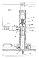
Figure 2 shows a perspective view of thevalve 18, partly in transparency, of a laundry treating machine as perfigure 1 , -
Figure 3 shows, in a perspective exploded view, the valve offig. 2 -
Fig. 4 shows a perspective view of the valve offig. 2 completely closed and mounted in the final arrangement, -
Figures 5 and6 show respective schematic section views of the valve according to the invention, in two respective different working status. - With ref to
fig. 1 , showing the schematic of the hydraulic circuit of a machine according to a prior art, and specifically of the machine described in the cited European Application n.06 118 596.3 tray 12. - A
pump 13 and apipe 17 convey the condensate from thetray 12 to amain tank 14, which is removably associated to the machine and preferably placed in an upper region of the cabinet 2, so as to be easily extracted by the user. - A
secondary tank 16 is provided to be in fluid communication with thecondensate collection tray 12 by means of thepipe 17. - Valve means 18 control the condensate flows towards the
main tank 14 and thesecondary tank 16. - As it will be better understood later on, a specific embodiment and function of said valve means 18 will be the subject of the instant invention.
-
Pipe 17 branches in a plurality ofconduits respective tank -
Secondary tank 16 is also hydraulically connected with apipe 23 to an inlet openingsteamgenerator 22 of know type, so that the liquor contained intank 16 can be evaporated. - Steam produced by the
generator 22 flows through apipe 24 into the drum, or alternatively into the drying air conduit, not shown, for treating laundry. - When valve means 18 are in an open position, condensate liquor available in the
tray 12 during or after a laundry drying operation is pumped by thepump 13 in thepipe 17 and divided between theprincipal tank 14 and thesecondary tank 16. In this way a portion of the total amount of liquid extracted from laundry is saved in thesecondary tank 16 and made available to be reused for a subsequent steam treatment. When valve means 18 are in a closed position all the amount of condensate liquor pumped from thetray 12 is flowed into theprincipal tank 14 though a opening 25 that is placed at thepipe 19 outlet when the machine is in use. Said opening 25 serves also as overflow opening allowing the condensate. - According to the invention, said
valve 18 is selectively controllable in its operation, not only in the sense that it may be opened or closed by an external command, but also in the sense that it contains a type of filter, which will be better described later on, whose introduction in the valve body determines the opening of the same valve, and inversely whose disengagement from the valve body determines its closing. - With ref. to the figures from 2 to 6, said
valve 18 is substancially shaped as an outer cylindrical, internally hollow body, 21; to one of its ends saidpipe 17 is connected, into which the condensate, coming from thetray 12, is flowing. - On a side portion of said
hollow body 21 an opening 40 is made, which branches out into theconduit 20 bound to saidsecondary tank 16. - Inside said
hollow body 21 the actual filtering means 43 is lodged, which is made of a cylindrical element working as a support and a frame for a filteringseptum 44 with very close mesh nets. - The working of said filter/valve 10 is as follows: when said filtering
element 43 is being introduced into saidhollow body 21, the condensed water coming from thepipe 17 enters said same hollow body and thefiltering element 43, which is closed on the opposite end. - From the inside of said filtering element the condensed water, which may also be mixed with lint and foreign materials, filters trough the filtering
septum 44, and gets out, flowing into the ring shaped inter-space between said septum and the inner surface of said hollow body. - From said gap the condensed water, then filtered, gets into said opening 40 and then, through said
pipe 20, into saidsecondary tank 16. - The filtering element and its operation have been just described; in the following the
valve 18 and its operation will be in detail explained. - With ref. to
figures 6 and 7, said valve comprises said outer andhollow body 21, and is internally provided with anannular relief 45, which is coaxial and internally opened with anopening 46. - To its turn said filtering
element 43 is provided to its end, turned to saidpipe 17, with afirst extension 47 apt of crossing said opening 46 and to contact, by pressure, an essentially flat and closingmember 48, placed between the affluent mouth 17-A of saidpipe 17 and saidannular relief 45. - Advantageously said
closing member 48 is provided towards said filteringelement 43 with a corresponding and substantially coaxial and aligned second extension 48-A apt to engage saidfirst extension 47. - The reciprocal sizes of said opening 46, of said
annular relief 45 and of saidclosing member 48 are such that saidclosing member 48 is apt of abut up on saidannular relief 45, and in this position said opening 46 is being fully closed. - A preferably
spiral spring 50 is interposed between the inner end side of saidhollow body 21, towards saidpipe 17, and the side 48-B, in front of it, of saidclosing member 48; said spring works on compression, and is preferably pre-loaded. - The operation of said device is as follows:
- when the filtering element has to be extracted, it will be enough to disengage it from said
outer body 21 according to known modes, for instance to reciprocally threatedmeans outer body 21 and a respective portion, turned outbound, of said filtering element 43.- - After having disengaged and extracted the filtering element 43 (
Fig. 6 ), the pressure of saidfirst extension 47 against said second extension 48-B of saidclosing member 48 fails, said pressure keeping said closingmember 48 away from said annular relief 45 (fig. 5 ); - As said pressure fails, said
closing member 48, due to the contrary action of saidspring 50, is being moved going into contact with saidrelief 45, pushing against it, what causes the closure of said opening 46. - So said valve, generally identified as 18, is being automatically closed by the simple extraction of the
filtering element 43 out of said outer body 21 (Fig. 6 ). - If on the contrary said filtering element is being introduced, the just described operations are obviously reversed (
fig. 5 ), resulting in the opening of said valve, and the condensed moisture is: - first of all filtered,
- and the made to flow into said
conduit 20 to be let into saidsecondary tank 16. - It will be now clear to the man skilled in the art a further advantage of the invention: in the facts not only the sought result of filtering the condensed moisture directed to the
secondary tank 16 is achieved, what is the main purpose of the invention, but a further useful result is obtained, consisting in the fact that, when one wishes to remove the filtering septum itself to carry out a normal cleaning or maintenance operation, said simple operation of filter extraction automatically blocks the condensed moisture inflow both into thesecondary tank 16, what is the main goal, but also prevents any moisture leakage outside of the machine across the same opening from where the filtering septum itself is extracted. - With obvious and well imaginable drawbacks.
- With ref. to
fig. 3 , a further improvement consists in the fact that saidvalve 18 is positioned in such a way that the filteringelement 43 be directly accessible from the front machine, and that it can be extracted from, or engaged into saidouter body 21, through the simple rotation of a control element, as arotating knob 54, placed outside thefiltering element 43 itself.
Claims (11)
- Household drying machine comprising:- a rotating drum for the containment and the drying of a laundry load,- an air circulation duct able of circulating a drying air flow across said drum,- a moisture condenser (1) for the drying air, apt of intercepting the air-flow out of said drum,- a tray (12) for the collection of the condensed moisture from said condenser (1),- hydraulic means able of drawing at least a part of the water contained in said tray, and of conveying it into diffusion means (22), even at a steam state, or as a spray, directly into said drum, or into said air circulation duct,- wherein said hydraulic means comprise an hydraulic pipe (17) going out of said tray (12) and eventually provided with a respective pump (13), able of transferring the water from said tray into said hydraulic pipe,- which branches out (19) directly into a main tank (14) and, through a selectively controllable valve (18), into a secondary tank (16) which is connected to a channel (23) and to said diffusion or steaming means (22),- characterized in that said selectively controllable valve (18) comprises a filtering means (43) able of filtering the liquid flow crossing it.
- Drying machine according to claim 1, characterized in that said filtering means (43) can be detached, and preferably extracted, from the body (21) of said valve (18).
- Drying machine according to claim 2, characterized in that said filtering means (43), when introduced into said valve (18), allows the liquid flow, and that when extracted from said valve, the inlet access of said pipe (17) into said valve is automatically closed.
- Drying machine according to claim 3, characterized in that said valve (18) is shaped as an hollow body (21), one end of it being connected to said pipe (17).
- Drying machine according to claims 3 or 4, characterized in that said channel (23), inflowing into said secondary tank (16), is connected to a side portion od said hollow body (21) through a respective opening (40).
- Drying machine according to one of the claims 4 or 5, characterized in that said filtering means (43) comprises a filtering septum (44), preferably provided with close mesh nets.
- Machine according to claim 6, characterized in that said hollow body (21) is provided on its inner surface with an annular relief (45) with an inner opening (46), that a closing member (48) is interposed between said annular relief (45) and the inlet mouth (17-A) of said pipe (17), and is able of closing said inner opening (46), in that said filtering means is solidly connected to a first extension (47) turned to said closing member (48) and that said first extension (47) is able to selectively engage by pushing with said closing means (48) so as to allow the liquid flow circulation across said inner opening (46), or to prevent said circulation.
- Drying machine according to claim 7, characterized in that between said closing member (48) and said first extension (47) a second extension (48-A) is provided, which is firmly associated to said closing member (48) and is apt to contact and be pressed by said first extension (47).
- Drying machine according to claim 8, characterized in that said valve (18) is provided with an elastic means (50), interposed between said closing member (48) and the inner end side (55) which is turned to the inlet access of said pipe (17), of said hollow body (20).
- Drying machine according to any of the previous claims, characterized in that said hollow body (20) and said filtering element (43) can be reciprocally engaged and dis-engaged , preferably through a threading coupling.
- Drying machine according to any of the previous claims, characterized in that said filtering means (43) comprises a control means, preferably a rotating knob, placed and accessible on the front side of said machine, apt to selectively engage or disengage it out of said hollow body (20).
Priority Applications (7)
| Application Number | Priority Date | Filing Date | Title |
|---|---|---|---|
| ES07108016T ES2351260T3 (en) | 2007-05-11 | 2007-05-11 | DRESS DRESS IMPROVED WITH RESTORATION OPERATION. |
| AT07108016T ATE486990T1 (en) | 2007-05-11 | 2007-05-11 | Tumble dryer with refresh function |
| PL07108016T PL1990466T3 (en) | 2007-05-11 | 2007-05-11 | Improved laundry dryer with refreshment operation |
| DE602007010247T DE602007010247D1 (en) | 2007-05-11 | 2007-05-11 | Clothes dryer with refreshing function |
| EP07108016A EP1990466B1 (en) | 2007-05-11 | 2007-05-11 | Improved laundry dryer with refreshment operation |
| PCT/EP2008/003660 WO2008138526A1 (en) | 2007-05-11 | 2008-05-07 | Improved laundry dryer with refreshment operation |
| RU2009145941/12A RU2455408C2 (en) | 2007-05-11 | 2008-05-07 | Improved drying machine for linen with freshening function |
Applications Claiming Priority (1)
| Application Number | Priority Date | Filing Date | Title |
|---|---|---|---|
| EP07108016A EP1990466B1 (en) | 2007-05-11 | 2007-05-11 | Improved laundry dryer with refreshment operation |
Publications (2)
| Publication Number | Publication Date |
|---|---|
| EP1990466A1 true EP1990466A1 (en) | 2008-11-12 |
| EP1990466B1 EP1990466B1 (en) | 2010-11-03 |
Family
ID=38543840
Family Applications (1)
| Application Number | Title | Priority Date | Filing Date |
|---|---|---|---|
| EP07108016A Active EP1990466B1 (en) | 2007-05-11 | 2007-05-11 | Improved laundry dryer with refreshment operation |
Country Status (7)
| Country | Link |
|---|---|
| EP (1) | EP1990466B1 (en) |
| AT (1) | ATE486990T1 (en) |
| DE (1) | DE602007010247D1 (en) |
| ES (1) | ES2351260T3 (en) |
| PL (1) | PL1990466T3 (en) |
| RU (1) | RU2455408C2 (en) |
| WO (1) | WO2008138526A1 (en) |
Cited By (14)
| Publication number | Priority date | Publication date | Assignee | Title |
|---|---|---|---|---|
| EP2314758A1 (en) * | 2009-10-20 | 2011-04-27 | Candy S.p.A. | A laundry dryer machine having a filter for condensed water |
| WO2011064161A1 (en) * | 2009-11-26 | 2011-06-03 | BSH Bosch und Siemens Hausgeräte GmbH | Laundry dryer having a condensate collector |
| EP2389474A2 (en) * | 2008-12-24 | 2011-11-30 | LG Electronics Inc. | Clothes treating apparatus with liquid supply unit |
| WO2011157560A1 (en) * | 2010-06-16 | 2011-12-22 | BSH Bosch und Siemens Hausgeräte GmbH | Condensate tank for a condenser clothes dryer, condenser clothes dryer, and method for operating a condenser clothes dryer |
| US8132339B2 (en) * | 2007-08-03 | 2012-03-13 | Lg Electronics Inc. | Cloth treating apparatus |
| ITTO20110812A1 (en) * | 2011-09-12 | 2013-03-13 | Indesit Co Spa | DRYING MACHINE OR WASHING MACHINE INCLUDING VEHICLES FOR THE TREATMENT OF CLOTHS THROUGH THE USE OF STEAMED CONDENSATE WATER |
| EP2568075A1 (en) * | 2011-09-12 | 2013-03-13 | Indesit Company S.p.A. | Drying or washing/drying machine comprising means for treating laundry items by using vaporized condensed water |
| WO2013045298A1 (en) * | 2011-09-26 | 2013-04-04 | Arcelik Anonim Sirketi | Condensate type laundry dryer |
| EP2610399A1 (en) * | 2011-12-28 | 2013-07-03 | Electrolux Home Products Corporation N.V. | Laundry drying domestic appliance having a liquid reservoir |
| WO2014102317A2 (en) * | 2012-12-28 | 2014-07-03 | Arcelik Anonim Sirketi | A laundry dryer comprising a filter |
| WO2014169955A1 (en) * | 2013-04-17 | 2014-10-23 | Electrolux Appliances Aktiebolag | Laundry dryer |
| EP3133203A1 (en) * | 2015-08-17 | 2017-02-22 | Lg Electronics Inc. | Clothes dryer |
| DE102015114255A1 (en) | 2015-08-27 | 2017-03-02 | Miele & Cie. Kg | Tumble dryer with a rotatably mounted in a housing drum, condensate filter for a tumble dryer |
| WO2017211819A1 (en) * | 2016-06-09 | 2017-12-14 | Arcelik Anonim Sirketi | A laundry dryer from which the condensate is discharged |
Families Citing this family (2)
| Publication number | Priority date | Publication date | Assignee | Title |
|---|---|---|---|---|
| US20130255094A1 (en) * | 2012-03-27 | 2013-10-03 | Bsh Bosch Und Siemens Hausgerate Gmbh | Clothes treatment appliance with water container and a transfer pipe |
| DE102014217355A1 (en) * | 2014-08-29 | 2016-03-03 | BSH Hausgeräte GmbH | Fluid connection device for a household appliance, and household appliance with such a |
Citations (4)
| Publication number | Priority date | Publication date | Assignee | Title |
|---|---|---|---|---|
| DE10260151A1 (en) * | 2002-12-20 | 2004-07-01 | BSH Bosch und Siemens Hausgeräte GmbH | Clothes dryer and process for removing odors from textiles |
| EP1564325A1 (en) * | 2004-02-10 | 2005-08-17 | Electrolux Home Products Corporation N.V. | Improved clothes drying machine with clothes smoothing ability |
| US20050278983A1 (en) * | 2004-03-01 | 2005-12-22 | Maytag Corporation | Filter vent for drying cabinet |
| US20060112585A1 (en) * | 2004-11-10 | 2006-06-01 | Lg Electronics, Inc. | Operation method for combination dryer |
Family Cites Families (3)
| Publication number | Priority date | Publication date | Assignee | Title |
|---|---|---|---|---|
| SU1587093A1 (en) * | 1988-03-23 | 1990-08-23 | В.П.Алешин | Drying machine for linen |
| DK0999302T3 (en) * | 1998-10-21 | 2003-12-01 | Whirlpool Co | Dryer with a heat pump |
| PL1887127T3 (en) * | 2006-08-08 | 2017-03-31 | Electrolux Home Products Corporation N.V. | Laundry treating machine |
-
2007
- 2007-05-11 AT AT07108016T patent/ATE486990T1/en not_active IP Right Cessation
- 2007-05-11 PL PL07108016T patent/PL1990466T3/en unknown
- 2007-05-11 DE DE602007010247T patent/DE602007010247D1/en active Active
- 2007-05-11 EP EP07108016A patent/EP1990466B1/en active Active
- 2007-05-11 ES ES07108016T patent/ES2351260T3/en active Active
-
2008
- 2008-05-07 RU RU2009145941/12A patent/RU2455408C2/en active
- 2008-05-07 WO PCT/EP2008/003660 patent/WO2008138526A1/en active Application Filing
Patent Citations (4)
| Publication number | Priority date | Publication date | Assignee | Title |
|---|---|---|---|---|
| DE10260151A1 (en) * | 2002-12-20 | 2004-07-01 | BSH Bosch und Siemens Hausgeräte GmbH | Clothes dryer and process for removing odors from textiles |
| EP1564325A1 (en) * | 2004-02-10 | 2005-08-17 | Electrolux Home Products Corporation N.V. | Improved clothes drying machine with clothes smoothing ability |
| US20050278983A1 (en) * | 2004-03-01 | 2005-12-22 | Maytag Corporation | Filter vent for drying cabinet |
| US20060112585A1 (en) * | 2004-11-10 | 2006-06-01 | Lg Electronics, Inc. | Operation method for combination dryer |
Cited By (19)
| Publication number | Priority date | Publication date | Assignee | Title |
|---|---|---|---|---|
| US8132339B2 (en) * | 2007-08-03 | 2012-03-13 | Lg Electronics Inc. | Cloth treating apparatus |
| EP2389474A4 (en) * | 2008-12-24 | 2013-11-20 | Lg Electronics Inc | Clothes treating apparatus with liquid supply unit |
| EP2389474A2 (en) * | 2008-12-24 | 2011-11-30 | LG Electronics Inc. | Clothes treating apparatus with liquid supply unit |
| EP2314758A1 (en) * | 2009-10-20 | 2011-04-27 | Candy S.p.A. | A laundry dryer machine having a filter for condensed water |
| WO2011064161A1 (en) * | 2009-11-26 | 2011-06-03 | BSH Bosch und Siemens Hausgeräte GmbH | Laundry dryer having a condensate collector |
| WO2011157560A1 (en) * | 2010-06-16 | 2011-12-22 | BSH Bosch und Siemens Hausgeräte GmbH | Condensate tank for a condenser clothes dryer, condenser clothes dryer, and method for operating a condenser clothes dryer |
| ITTO20110812A1 (en) * | 2011-09-12 | 2013-03-13 | Indesit Co Spa | DRYING MACHINE OR WASHING MACHINE INCLUDING VEHICLES FOR THE TREATMENT OF CLOTHS THROUGH THE USE OF STEAMED CONDENSATE WATER |
| EP2568075A1 (en) * | 2011-09-12 | 2013-03-13 | Indesit Company S.p.A. | Drying or washing/drying machine comprising means for treating laundry items by using vaporized condensed water |
| WO2013045298A1 (en) * | 2011-09-26 | 2013-04-04 | Arcelik Anonim Sirketi | Condensate type laundry dryer |
| EP2610399A1 (en) * | 2011-12-28 | 2013-07-03 | Electrolux Home Products Corporation N.V. | Laundry drying domestic appliance having a liquid reservoir |
| WO2014102317A2 (en) * | 2012-12-28 | 2014-07-03 | Arcelik Anonim Sirketi | A laundry dryer comprising a filter |
| WO2014102317A3 (en) * | 2012-12-28 | 2014-08-28 | Arcelik Anonim Sirketi | A laundry dryer comprising a filter |
| WO2014169955A1 (en) * | 2013-04-17 | 2014-10-23 | Electrolux Appliances Aktiebolag | Laundry dryer |
| CN105518208A (en) * | 2013-04-17 | 2016-04-20 | 伊莱克斯家用电器股份公司 | Laundry dryer |
| US10196773B2 (en) | 2013-04-17 | 2019-02-05 | Electrolux Appliances Aktiebolag | Laundry dryer |
| EP3133203A1 (en) * | 2015-08-17 | 2017-02-22 | Lg Electronics Inc. | Clothes dryer |
| US10619290B2 (en) | 2015-08-17 | 2020-04-14 | Lg Electronics Inc. | Clothes dryer |
| DE102015114255A1 (en) | 2015-08-27 | 2017-03-02 | Miele & Cie. Kg | Tumble dryer with a rotatably mounted in a housing drum, condensate filter for a tumble dryer |
| WO2017211819A1 (en) * | 2016-06-09 | 2017-12-14 | Arcelik Anonim Sirketi | A laundry dryer from which the condensate is discharged |
Also Published As
| Publication number | Publication date |
|---|---|
| RU2455408C2 (en) | 2012-07-10 |
| ATE486990T1 (en) | 2010-11-15 |
| EP1990466B1 (en) | 2010-11-03 |
| DE602007010247D1 (en) | 2010-12-16 |
| PL1990466T3 (en) | 2011-04-29 |
| RU2009145941A (en) | 2011-06-20 |
| WO2008138526A1 (en) | 2008-11-20 |
| ES2351260T3 (en) | 2011-02-02 |
Similar Documents
| Publication | Publication Date | Title |
|---|---|---|
| EP1990466B1 (en) | Improved laundry dryer with refreshment operation | |
| EP2120672B1 (en) | Energy-optimized automatic cleaning machine | |
| AU2013387149B2 (en) | Laundry dryer | |
| US8079157B2 (en) | Dryer comprising a heat sink and a condensate container | |
| CN105624967B (en) | A kind of drying washing machine with laundry care function | |
| US20120024801A1 (en) | Household laundry dryer and filtering method | |
| EP2762632B1 (en) | Washing method | |
| US20220106728A1 (en) | Fabric treating appliance with pelletizer | |
| SI25814A (en) | Condensation dryer | |
| EP2719819B1 (en) | Heat pump laundry dryer | |
| WO2020046241A2 (en) | A laundry washing and/or drying machine comprising a filter group | |
| DE3934434A1 (en) | Washing machine with conical water-tight drum - in which double-walled drum consists of cylindrical perforated inner wall and conical outer jacket | |
| EP1967640A1 (en) | Fabric processing apparatus | |
| US4483160A (en) | Dry cleaning apparatus for cleaning pieces of fabric | |
| RU2446239C2 (en) | Household dryer for linen | |
| WO2019210747A1 (en) | Washer dryer combo | |
| KR101176486B1 (en) | Vapor upsteam interceptor of washing machine | |
| EP3146882A1 (en) | Dishwasher, in particular domestic dishwasher | |
| EP1074207B1 (en) | Espresso coffee machine | |
| EP3008237B1 (en) | Laundry treatment apparatus having a condensate tank and method of condensate collecting and draining | |
| JP7222454B2 (en) | Airwash device for clothes treatment equipment and clothes treatment equipment | |
| CN114763668A (en) | Clothes dryer provided with steam generator | |
| DE20023123U1 (en) | Front-loading washing machine has insert body inserted into and removed from shaft via collar opening to extend to filter holder, forming filter bearer at lower end, handle at upper end |
Legal Events
| Date | Code | Title | Description |
|---|---|---|---|
| PUAI | Public reference made under article 153(3) epc to a published international application that has entered the european phase |
Free format text: ORIGINAL CODE: 0009012 |
|
| AK | Designated contracting states |
Kind code of ref document: A1 Designated state(s): AT BE BG CH CY CZ DE DK EE ES FI FR GB GR HU IE IS IT LI LT LU LV MC MT NL PL PT RO SE SI SK TR |
|
| AX | Request for extension of the european patent |
Extension state: AL BA HR MK RS |
|
| AKX | Designation fees paid | ||
| 17P | Request for examination filed |
Effective date: 20090417 |
|
| RBV | Designated contracting states (corrected) |
Designated state(s): AT BE BG CH CY CZ DE DK EE ES FI FR GB GR HU IE IS IT LI LT LU LV MC MT NL PL PT RO SE SI SK TR |
|
| RIN1 | Information on inventor provided before grant (corrected) |
Inventor name: NOVIELLO, FLAVIO Inventor name: SARTOR, LUCIANO |
|
| GRAP | Despatch of communication of intention to grant a patent |
Free format text: ORIGINAL CODE: EPIDOSNIGR1 |
|
| GRAS | Grant fee paid |
Free format text: ORIGINAL CODE: EPIDOSNIGR3 |
|
| GRAA | (expected) grant |
Free format text: ORIGINAL CODE: 0009210 |
|
| AK | Designated contracting states |
Kind code of ref document: B1 Designated state(s): AT BE BG CH CY CZ DE DK EE ES FI FR GB GR HU IE IS IT LI LT LU LV MC MT NL PL PT RO SE SI SK TR |
|
| REG | Reference to a national code |
Ref country code: GB Ref legal event code: FG4D |
|
| REG | Reference to a national code |
Ref country code: CH Ref legal event code: EP |
|
| REG | Reference to a national code |
Ref country code: IE Ref legal event code: FG4D |
|
| REF | Corresponds to: |
Ref document number: 602007010247 Country of ref document: DE Date of ref document: 20101216 Kind code of ref document: P |
|
| REG | Reference to a national code |
Ref country code: ES Ref legal event code: FG2A Effective date: 20110121 |
|
| REG | Reference to a national code |
Ref country code: NL Ref legal event code: VDEP Effective date: 20101103 |
|
| RAP2 | Party data changed (patent owner data changed or rights of a patent transferred) |
Owner name: ELECTROLUX HOME PRODUCTS CORPORATION N.V. |
|
| LTIE | Lt: invalidation of european patent or patent extension |
Effective date: 20101103 |
|
| PG25 | Lapsed in a contracting state [announced via postgrant information from national office to epo] |
Ref country code: LT Free format text: LAPSE BECAUSE OF FAILURE TO SUBMIT A TRANSLATION OF THE DESCRIPTION OR TO PAY THE FEE WITHIN THE PRESCRIBED TIME-LIMIT Effective date: 20101103 |
|
| REG | Reference to a national code |
Ref country code: PL Ref legal event code: T3 |
|
| PG25 | Lapsed in a contracting state [announced via postgrant information from national office to epo] |
Ref country code: FI Free format text: LAPSE BECAUSE OF FAILURE TO SUBMIT A TRANSLATION OF THE DESCRIPTION OR TO PAY THE FEE WITHIN THE PRESCRIBED TIME-LIMIT Effective date: 20101103 Ref country code: BG Free format text: LAPSE BECAUSE OF FAILURE TO SUBMIT A TRANSLATION OF THE DESCRIPTION OR TO PAY THE FEE WITHIN THE PRESCRIBED TIME-LIMIT Effective date: 20110203 Ref country code: PT Free format text: LAPSE BECAUSE OF FAILURE TO SUBMIT A TRANSLATION OF THE DESCRIPTION OR TO PAY THE FEE WITHIN THE PRESCRIBED TIME-LIMIT Effective date: 20110303 Ref country code: SI Free format text: LAPSE BECAUSE OF FAILURE TO SUBMIT A TRANSLATION OF THE DESCRIPTION OR TO PAY THE FEE WITHIN THE PRESCRIBED TIME-LIMIT Effective date: 20101103 Ref country code: LV Free format text: LAPSE BECAUSE OF FAILURE TO SUBMIT A TRANSLATION OF THE DESCRIPTION OR TO PAY THE FEE WITHIN THE PRESCRIBED TIME-LIMIT Effective date: 20101103 Ref country code: AT Free format text: LAPSE BECAUSE OF FAILURE TO SUBMIT A TRANSLATION OF THE DESCRIPTION OR TO PAY THE FEE WITHIN THE PRESCRIBED TIME-LIMIT Effective date: 20101103 Ref country code: IS Free format text: LAPSE BECAUSE OF FAILURE TO SUBMIT A TRANSLATION OF THE DESCRIPTION OR TO PAY THE FEE WITHIN THE PRESCRIBED TIME-LIMIT Effective date: 20110303 Ref country code: SE Free format text: LAPSE BECAUSE OF FAILURE TO SUBMIT A TRANSLATION OF THE DESCRIPTION OR TO PAY THE FEE WITHIN THE PRESCRIBED TIME-LIMIT Effective date: 20101103 Ref country code: NL Free format text: LAPSE BECAUSE OF FAILURE TO SUBMIT A TRANSLATION OF THE DESCRIPTION OR TO PAY THE FEE WITHIN THE PRESCRIBED TIME-LIMIT Effective date: 20101103 |
|
| PG25 | Lapsed in a contracting state [announced via postgrant information from national office to epo] |
Ref country code: GR Free format text: LAPSE BECAUSE OF FAILURE TO SUBMIT A TRANSLATION OF THE DESCRIPTION OR TO PAY THE FEE WITHIN THE PRESCRIBED TIME-LIMIT Effective date: 20110204 |
|
| RAP2 | Party data changed (patent owner data changed or rights of a patent transferred) |
Owner name: ELECTROLUX HOME PRODUCTS CORPORATION N.V. |
|
| PG25 | Lapsed in a contracting state [announced via postgrant information from national office to epo] |
Ref country code: EE Free format text: LAPSE BECAUSE OF FAILURE TO SUBMIT A TRANSLATION OF THE DESCRIPTION OR TO PAY THE FEE WITHIN THE PRESCRIBED TIME-LIMIT Effective date: 20101103 Ref country code: CZ Free format text: LAPSE BECAUSE OF FAILURE TO SUBMIT A TRANSLATION OF THE DESCRIPTION OR TO PAY THE FEE WITHIN THE PRESCRIBED TIME-LIMIT Effective date: 20101103 Ref country code: BE Free format text: LAPSE BECAUSE OF FAILURE TO SUBMIT A TRANSLATION OF THE DESCRIPTION OR TO PAY THE FEE WITHIN THE PRESCRIBED TIME-LIMIT Effective date: 20101103 |
|
| PG25 | Lapsed in a contracting state [announced via postgrant information from national office to epo] |
Ref country code: SK Free format text: LAPSE BECAUSE OF FAILURE TO SUBMIT A TRANSLATION OF THE DESCRIPTION OR TO PAY THE FEE WITHIN THE PRESCRIBED TIME-LIMIT Effective date: 20101103 Ref country code: DK Free format text: LAPSE BECAUSE OF FAILURE TO SUBMIT A TRANSLATION OF THE DESCRIPTION OR TO PAY THE FEE WITHIN THE PRESCRIBED TIME-LIMIT Effective date: 20101103 Ref country code: RO Free format text: LAPSE BECAUSE OF FAILURE TO SUBMIT A TRANSLATION OF THE DESCRIPTION OR TO PAY THE FEE WITHIN THE PRESCRIBED TIME-LIMIT Effective date: 20101103 |
|
| PLBE | No opposition filed within time limit |
Free format text: ORIGINAL CODE: 0009261 |
|
| STAA | Information on the status of an ep patent application or granted ep patent |
Free format text: STATUS: NO OPPOSITION FILED WITHIN TIME LIMIT |
|
| 26N | No opposition filed |
Effective date: 20110804 |
|
| REG | Reference to a national code |
Ref country code: DE Ref legal event code: R097 Ref document number: 602007010247 Country of ref document: DE Effective date: 20110804 |
|
| PG25 | Lapsed in a contracting state [announced via postgrant information from national office to epo] |
Ref country code: MT Free format text: LAPSE BECAUSE OF FAILURE TO SUBMIT A TRANSLATION OF THE DESCRIPTION OR TO PAY THE FEE WITHIN THE PRESCRIBED TIME-LIMIT Effective date: 20101103 Ref country code: MC Free format text: LAPSE BECAUSE OF NON-PAYMENT OF DUE FEES Effective date: 20110531 |
|
| REG | Reference to a national code |
Ref country code: CH Ref legal event code: PL |
|
| PG25 | Lapsed in a contracting state [announced via postgrant information from national office to epo] |
Ref country code: LI Free format text: LAPSE BECAUSE OF NON-PAYMENT OF DUE FEES Effective date: 20110531 Ref country code: CH Free format text: LAPSE BECAUSE OF NON-PAYMENT OF DUE FEES Effective date: 20110531 |
|
| REG | Reference to a national code |
Ref country code: FR Ref legal event code: CA Effective date: 20120116 |
|
| REG | Reference to a national code |
Ref country code: IE Ref legal event code: MM4A |
|
| PG25 | Lapsed in a contracting state [announced via postgrant information from national office to epo] |
Ref country code: IE Free format text: LAPSE BECAUSE OF NON-PAYMENT OF DUE FEES Effective date: 20110511 |
|
| PGFP | Annual fee paid to national office [announced via postgrant information from national office to epo] |
Ref country code: ES Payment date: 20120525 Year of fee payment: 6 |
|
| PG25 | Lapsed in a contracting state [announced via postgrant information from national office to epo] |
Ref country code: CY Free format text: LAPSE BECAUSE OF FAILURE TO SUBMIT A TRANSLATION OF THE DESCRIPTION OR TO PAY THE FEE WITHIN THE PRESCRIBED TIME-LIMIT Effective date: 20101103 Ref country code: LU Free format text: LAPSE BECAUSE OF NON-PAYMENT OF DUE FEES Effective date: 20110511 |
|
| PGFP | Annual fee paid to national office [announced via postgrant information from national office to epo] |
Ref country code: PL Payment date: 20130425 Year of fee payment: 7 |
|
| PG25 | Lapsed in a contracting state [announced via postgrant information from national office to epo] |
Ref country code: TR Free format text: LAPSE BECAUSE OF FAILURE TO SUBMIT A TRANSLATION OF THE DESCRIPTION OR TO PAY THE FEE WITHIN THE PRESCRIBED TIME-LIMIT Effective date: 20101103 |
|
| PG25 | Lapsed in a contracting state [announced via postgrant information from national office to epo] |
Ref country code: HU Free format text: LAPSE BECAUSE OF FAILURE TO SUBMIT A TRANSLATION OF THE DESCRIPTION OR TO PAY THE FEE WITHIN THE PRESCRIBED TIME-LIMIT Effective date: 20101103 |
|
| PG25 | Lapsed in a contracting state [announced via postgrant information from national office to epo] |
Ref country code: PL Free format text: LAPSE BECAUSE OF NON-PAYMENT OF DUE FEES Effective date: 20140511 |
|
| REG | Reference to a national code |
Ref country code: PL Ref legal event code: LAPE |
|
| REG | Reference to a national code |
Ref country code: ES Ref legal event code: FD2A Effective date: 20160205 |
|
| PG25 | Lapsed in a contracting state [announced via postgrant information from national office to epo] |
Ref country code: ES Free format text: LAPSE BECAUSE OF NON-PAYMENT OF DUE FEES Effective date: 20140512 |
|
| REG | Reference to a national code |
Ref country code: FR Ref legal event code: PLFP Year of fee payment: 10 |
|
| REG | Reference to a national code |
Ref country code: FR Ref legal event code: PLFP Year of fee payment: 11 |
|
| REG | Reference to a national code |
Ref country code: FR Ref legal event code: PLFP Year of fee payment: 12 |
|
| PGFP | Annual fee paid to national office [announced via postgrant information from national office to epo] |
Ref country code: IT Payment date: 20220524 Year of fee payment: 16 Ref country code: GB Payment date: 20220519 Year of fee payment: 16 Ref country code: FR Payment date: 20220523 Year of fee payment: 16 Ref country code: DE Payment date: 20220519 Year of fee payment: 16 |
|
| P01 | Opt-out of the competence of the unified patent court (upc) registered |
Effective date: 20230625 |
|
| REG | Reference to a national code |
Ref country code: DE Ref legal event code: R119 Ref document number: 602007010247 Country of ref document: DE |
|
| GBPC | Gb: european patent ceased through non-payment of renewal fee |
Effective date: 20230511 |