EP1985996A1 - Analytic system for photometric determination of an analyte in a body fluid using an analytic device and a test panel to be fitted to the analytic device - Google Patents
Analytic system for photometric determination of an analyte in a body fluid using an analytic device and a test panel to be fitted to the analytic device Download PDFInfo
- Publication number
- EP1985996A1 EP1985996A1 EP07008615A EP07008615A EP1985996A1 EP 1985996 A1 EP1985996 A1 EP 1985996A1 EP 07008615 A EP07008615 A EP 07008615A EP 07008615 A EP07008615 A EP 07008615A EP 1985996 A1 EP1985996 A1 EP 1985996A1
- Authority
- EP
- European Patent Office
- Prior art keywords
- value
- evaluation
- measuring
- values
- test carrier
- Prior art date
- Legal status (The legal status is an assumption and is not a legal conclusion. Google has not performed a legal analysis and makes no representation as to the accuracy of the status listed.)
- Withdrawn
Links
Images


Classifications
-
- G—PHYSICS
- G01—MEASURING; TESTING
- G01N—INVESTIGATING OR ANALYSING MATERIALS BY DETERMINING THEIR CHEMICAL OR PHYSICAL PROPERTIES
- G01N21/00—Investigating or analysing materials by the use of optical means, i.e. using sub-millimetre waves, infrared, visible or ultraviolet light
- G01N21/84—Systems specially adapted for particular applications
- G01N21/8483—Investigating reagent band
-
- Y—GENERAL TAGGING OF NEW TECHNOLOGICAL DEVELOPMENTS; GENERAL TAGGING OF CROSS-SECTIONAL TECHNOLOGIES SPANNING OVER SEVERAL SECTIONS OF THE IPC; TECHNICAL SUBJECTS COVERED BY FORMER USPC CROSS-REFERENCE ART COLLECTIONS [XRACs] AND DIGESTS
- Y10—TECHNICAL SUBJECTS COVERED BY FORMER USPC
- Y10T—TECHNICAL SUBJECTS COVERED BY FORMER US CLASSIFICATION
- Y10T436/00—Chemistry: analytical and immunological testing
- Y10T436/11—Automated chemical analysis
Definitions
- the present invention relates to an analysis system for the photometric determination of the concentration of an analyte in a body fluid with an analyzer and a test carrier.
- the test carrier has a receiving zone in which a photometrically detectable change takes place as a result of a reaction of a sample of body fluid contacted with the test carrier with a reagent contained in the test carrier.
- test carriers for the photometric determination of an analyte in a body fluid using disposable test elements, test carriers or test strips are known. They are used to determine the concentration of various analytes, such as glucose or cholesterol in the blood.
- the test carriers are usually in the form of test strips, but other forms of test elements, for example flat, approximately square plates, are also common.
- the test carriers contain reagents whose reaction with the sample leads to a detectable change which is measured with a measuring and evaluation device belonging to the system.
- photometric analysis systems in which the reaction causes a color change in a detection layer of the test element, which is measured photometrically.
- the intensity of the light reflected by the test carrier is examined.
- the photometric analysis systems When used properly, the photometric analysis systems usually work reliably. However, if the user does not apply the required care when using the devices or the test carriers or test strips, erroneous readings may result.
- Faulty measurement results can occasionally be attributed to an error in the microcontroller of the analyzer. Therefore, many devices are redundant and include two parallel microcontroller.
- the use of a second microcontroller (hardware) not only increases the space required in the analyzer, it also makes it more expensive. In addition, procedures must be created for the parallel processing of the measurement signals.
- the redundancy can be provided by a second software module be created.
- the processing overhead is greater, since two parallel programs must be processed.
- the programming is complicated. The determination of the analysis result takes longer due to parallel processing.
- the analysis system according to the invention for the photometric determination of an analyte in a body fluid comprises an analyzer and a test carrier.
- the test carrier has an evaluation zone in which a photometrically detectable change takes place as a result of a reaction of a sample of body fluid contacted with the test carrier with a reagent contained in the test carrier.
- the analyzer includes an optical transmitter for emitting light to the evaluation zone of the test carrier, an optical receiver for detecting light received from the evaluation zone, and for generating a measurement signal corresponding to the received light.
- the light from the evaluation zone can either be (diffusely) reflected at the evaluation zone or transmitted through the evaluation zone before it reaches the optical receiver.
- the measurement signal generated by the receiver corresponds to the intensity of the received light.
- the analyzer comprises a measuring and evaluation device with a measuring unit and an evaluation unit.
- the measurement signal received in the optical receiver is amplified and digitized. From the digitized measurement signal, the sought-after concentration value is determined in the evaluation unit by means of an evaluation algorithm, which comprises an association between values of the measurement signal and concentration values.
- the assignment between the values of the measuring signal and the concentration values can be stored as a formula, function or as a table.
- the analyzers partly output erroneous measurement results, which, however, do not suggest a systematic error.
- the occurring error occurs sporadically and depends, for example, on environmental influences, i. depending on the ambient temperature or environmental conditions, such as humidity or air pressure.
- the measuring and evaluation device of the analysis devices designed in the form of a microcomputer can produce erroneous results as a function of the values to be processed, that is to say the measuring signals applied to the input. Apparently results in a temporal occurrence of an error.
- Such an error can be detected in a simple manner if a control value, which is detected in the processing sequence after the execution of a calculation step for determining the measurement result, is compared by means of an expected value.
- the processing procedure comprises at least one computing step of a processor or microcomputer. In addition, it can also include further process and / or computation steps in order to determine the desired measurement result from the values of the measurement signal, for example a concentration value or a value representing a concentration.
- the measurement result could also be an "intermediate value" which is used in the processor for further processing.
- the control value is checked according to the invention by means of a control algorithm in which a deviation of the determined control value from an expected value is determined. Exceeds this deviation a predefined limit, an error in the measuring and evaluation is detected. At this point additional knowledge about the value of the control quantity is implemented in the system according to the invention. It is approximately known which behavior has the control value or in which coarse ranges the control value must lie. This can be determined by series of measurements in the laboratory or by reference systems which have redundantly constructed measuring and evaluation devices.
- control value is understood as a value during the processing of the measurement signal for determining the measurement result or the sought concentration value.
- the control value is particularly preferably the desired concentration value itself, so that the checking of the measuring and evaluation device takes place at the end of the determination of the concentration value.
- control value can also be formed from other "intermediate values" during the processing of the measured value, for example from processor-internal arithmetic variables which represent the concentration or from processed remainder values (intensity of the light reflected by the test carrier).
- the control quantity is recorded at a detection point.
- This detection point is a location in the processing flow within the processor, if at least one calculation step for determining the concentration value has already been carried out.
- the detection point is therefore behind the processing sequence behind at least one computing step (downstream). He can e.g. a location in the measuring and evaluation device or in the microcomputer or else a discharge point in a computer program, if the measuring and evaluation device is in the form of software in a microcomputer, e.g. in an ASIC, is implemented.
- control value is described as the concentration value.
- concentration value any other suitable value than Control value can be used.
- a reference concentration value is used as the expected value.
- the expected value and the control value are usually matched to one another such that the control value and the expected value are the same size. In other words, if, for example, the control value is a value of the concentration, then the expected value is also a value of the concentration.
- the concentration value is checked by means of a control algorithm in which a deviation of the determined concentration value from an expected value is determined, which can preferably be a reference concentration value which can be parameterized depending on the analyte to be measured, the test carrier or the determination method for determining the concentration value.
- a control algorithm in which a deviation of the determined concentration value from an expected value is determined, which can preferably be a reference concentration value which can be parameterized depending on the analyte to be measured, the test carrier or the determination method for determining the concentration value.
- a control algorithm in which a deviation of the determined concentration value from an expected value is determined, which can preferably be a reference concentration value which can be parameterized depending on the analyte to be measured, the test carrier or the determination method for determining the concentration value.
- general knowledge about the concentration value can be implemented. If the deviation of the concentration value from the reference concentration value exceeds a predefined limit value, an error is detected in the measuring and evaluation device.
- the concentration value determined with the measuring and evaluation device can be checked quickly and reliably.
- the determined concentration value is compared with a reference concentration value.
- a reference assignment is used, which is used in the control algorithm.
- a plurality of reference measurement values are assigned a plurality of reference concentration values by means of the reference assignment.
- To check a concentration value determined from the current measured value of the measuring signal first the reference value is selected, which is adjacent to the current measured value of the measuring signal is. From this reference value, the corresponding reference concentration value is determined by means of the reference assignment.
- the selected reference concentration value is compared with the determined concentration value, wherein the deviation must not exceed a predetermined limit value.
- the predefined limit value can be easily parameterized.
- the evaluation algorithm for determining the sought concentration value from the digitized measurement signal is preferably batch-specific.
- the evaluation algorithm is understood to mean the entirety of the stored function or relation and the variables defined in such a function, which can be variable parameters.
- the variables of the association between the values of the measurement signal and the concentration values included in the evaluation algorithm may depend on the test carriers used.
- the association between the measurement values of the measurement signal and the concentration values used for determining the concentration value is preferably batch-specific for the production batch of the test carriers used. Before the first use of a test carrier of a new production batch, therefore, information about the batch-specific assignment is imported into the analysis device and stored in a memory of the analysis device.
- the reference assignment is also preferably production batch-specific, so that the reference assignment also has to be stored in the analyzer before the first use of a test carrier of a new production lot.
- the reference map can either be loaded into the analyzer, i. be transmitted externally by means of a data carrier or via an interface.
- the reference assignment is then generated in another device and stored in a memory of the analyzer.
- the reference assignment can be generated in the analyzer itself. It is generated by the evaluation algorithm with predetermined reference measurements, each one Reference measured value is assigned a reference concentration value by applying the stored in the evaluation algorithm assignment. The generated reference assignment is then stored in the analyzer.
- the reference assignment can be stored as value pairs in the form of a "look-up table" or in another table form. At least ten, more preferably at least thirty pairs of values are preferably stored in the reference assignment. Within the scope of the invention, approximately fifty value pairs have proven to be particularly suitable. The more value pairs that are deposited, the more accurate the verification of the determined concentration value can be.
- the storage and / or the generation of the reference assignment must occur before the first use of a test carrier of a new production batch, since the reference assignment is production batches dependent and may differ for test carriers from different production batches as well as the allocation of the evaluation algorithm.
- the reference assignment of the control algorithm is created in the analyzer by using the assignment of the evaluation algorithm, the reference assignment can additionally be checked.
- the determined reference concentration values are checked for mathematical monotony, ie checked for whether the reference concentration values describe a function or a sequence with a gradient in the same direction.
- the knowledge of the concentration values as a function of the emitted light that is to say of the measuring signal, is used.
- the concentration falls monotonously. Therefore, the reference concentration values must also fall with increasing reference measurements.
- Photometric methods based on luminescence also show increasing values as the measured values increase Concentration values on.
- the reference concentration values must increase with increasing reference measured values.
- the reference assignment generated by applying the assignment of the evaluation algorithm can optionally be checked for "smoothness".
- the deviations between two successive reference concentration values must not be too great, in particular not exceed a predetermined parameterizable tolerance, which may be stored in a memory of the analyzer.
- the measuring and evaluation device can also be checked by detecting a plurality of successive auxiliary measured values of the measuring signal in the measuring unit at a plurality of measuring times.
- the successive auxiliary measured values are compared in the measuring and evaluation device with the respectively preceding auxiliary measured values. This checks whether the auxiliary measurement values form a mathematically monotonous function or sequence.
- the auxiliary measurements must therefore all have the same incline. If this is not the case, an error of the measuring and evaluation device is detected. It is clear to the person skilled in the art that this check can be carried out alternatively and / or in addition to checking the deviation of the control value from the expected value.
- FIG. 1 shows an analysis system 1 with an analyzer 2 and a test carrier 3, which is designed as a test strip and has an evaluation zone 4.
- a reagent is contained which, in the presence of an analyte in a body fluid, which is applied to the evaluation zone 4, causes a reaction whose change can be detected photometrically.
- the evaluation zone 4 of the test carrier 3 is irradiated by an optical transmitter 5 with light.
- the transmitter 5 is designed as a light source 6, in particular as a light-emitting diode. Of course, any other light sources may be present, which are connected in parallel or in series.
- the light emitted by the test carrier 3 is received by an optical receiver 7.
- the receiver 7 is a light sensor, in particular a photodiode 8.
- the light reflected by the test carrier 3 is referred to as remission.
- the intensity of the reflected light is measured and converted into a corresponding measurement signal.
- the measurement signal corresponding to the intensity of the received light is forwarded to a measuring and evaluation device 8 which comprises a measuring unit 9 and an evaluation unit 10.
- the measuring unit 9 includes an amplifier 11, a measuring circuit 12 formed as a band-pass filter or the like, and an A / D converter. At one Output 14 of the measuring unit 9 is then a digitized measurement signal 15 available, which is referred to as remission.
- the digitized measurement signal 15 is processed by the evaluation unit 10.
- the evaluation unit 10 includes a microcontroller 16 and a memory 17.
- an assignment 18 is implemented, by means of which a concentration value is determined from the measurement signal 15.
- the concentration value is checked for correctness by comparing it with a reference concentration value and determining the deviation from the reference concentration value. If the deviation exceeds a predetermined limit, an error is detected.
- the detected error is transmitted to a display unit 19 and displayed, for example, on a display 20. If the determined concentration value is correct, i. if the deviation is smaller than the limit value, the determined concentration value is displayed on the display 20.
- FIG. 2 shows the time course of the remission received by the receiver 7 (intensity of the light reflected from the test carrier 3).
- the remission is the measurement signal that is processed by the measuring unit 9.
- the measuring signal 15 digitized by the measuring unit 9 can be checked. This is based on the known knowledge of the temporal course of the remission, which can be described by a monotone decreasing curve.
- a plurality of auxiliary measurement values of the measurement signal is determined, the referred to in this embodiment as an intermediate measurement values or intermediate reflectance values, Rz 1, Rz 2 ...
- the auxiliary measurement values do not necessarily have to be values that are earlier than the measurement value used to determine the measurement result.
- the successive intermediate measured values Rz i become with the respectively preceding Measured value Rz i-1 compared. It is checked whether a mathematically monotonous curve is present. This method already controls the "quality" of the signal acquisition and detects an error of the measuring and evaluation device based on a faulty measurement.
- the intermediate measured value Rz i has a lower value than the immediately preceding intermediate measured value Rz i-1 . If this is not the case, then there is an error in the measuring unit 9. An error signal is output. If it is checked whether the intermediate measured values Rz i form a monotonically increasing function, the intermediate measured values Rz i must be greater than the directly preceding intermediate measured values Rz i-1 . Alternatively, the amount of deviation between two successive intermediate measured values could also be determined. This is sufficient if only unacceptable deviations of the intermediate measured values, so-called spikes, should be detected early.
- the value of the measurement signal ie the intermediate measured value Rz i , which differs from the preceding intermediate measured value Rz i-1 less than a predetermined limit value, is preferably used.
- This limit value can be parametrised easily. This ensures that the "correct" intermediate measured value is used as the current measured value of the measuring signal for determining the concentration value. This is the case if the temporal change of the measured value (remission value) is negligible.
- FIG. 3 represents the association between the values of the measurement signal R, ie the remission measured values, and the concentration values C.
- the assignment can be stored in the form of a table or a function or a curve.
- the assignment of the evaluation algorithm is approximated by a spline function.
- a spline function with a maximum of ten support points has proven to be suitable; an approximation by a spline function with at most five interpolation points is preferred.
- the spline function may be through be formed a third degree function.
- the parameters for the description of the third degree function are each dependent on the production batch of the test carrier 3 used and are respectively imported to the analyzer before the first use of a test carrier of a new production batch, this information (parameter) being stored in the memory 17 of the analyzer 2.
- this information (parameter) being stored in the memory 17 of the analyzer 2.
- a total of 16 parameters must be stored.
- a reference assignment is created after importing the information about the batch-specific assignment.
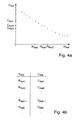
- Such a reference assignment between reference measured value R Ref (reference emission values ) and reference concentration values C Ref is in FIG. 4a shown.
- a plurality of predetermined reference measured values are applied to the assignment of the evaluation algorithm.
- a reference concentration value C Refi is created for each reference measured value R Refi .
- the reference mapping is formed for at least thirty, more preferably at least fifty, reference measurements.
- the reference mapping between reference measurements R ref and reference concentration values C ref may also be as in FIG. 4b shown in the form of a "look-up table".
- the reference measured value R Refi adjacent to the current measured value of the measuring signal is determined, and the reference concentration value C Refi of the reference assignment is determined. This selected reference concentration value is compared with the determined concentration value.
- a first and a second reference concentration value C Ref1 , C Ref2 are determined from a first and a second reference measured value R Ref1 , R Ref2 .
- first and second reference measured value R Ref1 , R Ref2 the values are selected that are adjacent to the current measured value of the measuring signal.
- the determination of Both reference concentration values C Ref1 , C Ref2 occur by means of the reference assignment .
- the determined concentration value is then checked by means of the control algorithm with the first and second reference concentration values C Ref1 , C Ref2 .
- the measured concentration value must be between the first and second reference concentration values C Ref1 , C Ref2 .
- An error of the measuring and evaluation device 8 is detected when the determined concentration value is not between the first and the second reference concentration value C Ref1 , C Ref2 , ie when the determined concentration value is greater than the first reference concentration value C Ref1 and less than the second reference concentration value C. Ref2 is.
- the limit value that is used to check the deviation of the concentration value from only one reference concentration value can also be determined.
Abstract
Description
Die vorliegende Erfindung betrifft ein Analysesystem zur photometrischen Bestimmung der Konzentration eines Analyten in einer Körperflüssigkeit mit einem Analysegerät und einem Testträger. Der Testträger weist eine Aufnahmezone auf, in der als Folge einer Reaktion eines mit dem Testträger kontaktierten Probe der Körperflüssigkeit mit einem in dem Testträger enthaltenen Reagenz eine photometrisch nachweisbare Änderung stattfindet.The present invention relates to an analysis system for the photometric determination of the concentration of an analyte in a body fluid with an analyzer and a test carrier. The test carrier has a receiving zone in which a photometrically detectable change takes place as a result of a reaction of a sample of body fluid contacted with the test carrier with a reagent contained in the test carrier.
Analysesysteme zur photometrischen Bestimmung eines Analyten in einer Körperflüssigkeit, die disposible Testelemente, Testträger oder Teststreifen verwenden, sind bekannt. Sie werden eingesetzt, um die Konzentration verschiedener Analyten, wie beispielsweise Glucose oder Cholesterin im Blut zu ermitteln. Die Testträger haben meist die Form von Teststreifen, jedoch sind auch andere Formen von Testelementen, beispielsweise flache, näherungsweise quadratische Plättchen, gebräuchlich.Analytical systems for the photometric determination of an analyte in a body fluid using disposable test elements, test carriers or test strips are known. They are used to determine the concentration of various analytes, such as glucose or cholesterol in the blood. The test carriers are usually in the form of test strips, but other forms of test elements, for example flat, approximately square plates, are also common.
In der Regel enthalten die Testträger Reagenzien, deren Reaktion mit der Probe zu einer detektierbaren Veränderung führt, die mit einer zum System gehörenden Mess- und Auswerteeinrichtung gemessen wird.As a rule, the test carriers contain reagents whose reaction with the sample leads to a detectable change which is measured with a measuring and evaluation device belonging to the system.
Gebräuchlich sind insbesondere photometrische Analysesysteme, bei denen die Reaktion eine Farbänderung in einer Nachweisschicht des Testelementes verursacht, die photometrisch gemessen wird. Hierbei wird in der Regel die Intensität des von dem Testträger reflektierten Lichtes untersucht.In particular photometric analysis systems are used, in which the reaction causes a color change in a detection layer of the test element, which is measured photometrically. As a rule, the intensity of the light reflected by the test carrier is examined.
Bei sachgemäßer Anwendung arbeiten die photometrischen Analysesysteme in der Regel zuverlässig. Wird die erforderliche Sorgfalt bei der Verwendung der Geräte oder der Testträger bzw. Teststreifen vom Benutzer jedoch nicht aufgebracht, können fehlerhafte Messwerte resultieren.When used properly, the photometric analysis systems usually work reliably. However, if the user does not apply the required care when using the devices or the test carriers or test strips, erroneous readings may result.
Trotzdem kann es auch bei sachgemäßer Anwendung zu fehlerhaften Messergebnissen kommen, insbesondere wenn Fabrikationsfehler beim Analysegerät oder beim Testträger vorliegen. Obwohl große Sorgfalt bei der Herstellung solcher Analysegeräte und Teststreifen verwendet wird, besteht das Bedürfnis, Fehlfunktionen des Messgerätes zu ermitteln, um fehlerhafte Analysewerte zu vermeiden. Da beispielsweise bei der Ermittlung der Konzentration des Glucosegehaltes das Messergebnis zur Therapie eines Patienten verwendet wird, insbesondere die Dosierung des Insulins bestimmt, ist ein fehlerfreier Analysewert besonders wichtig. Eine auf einem fehlerhaften Messergebnis basierende falsche Zugabe von Insulin (zu geringe oder zu hohe Insulinzugabe) kann zu körper- und lebensbedrohlichen Situationen führen.Nevertheless, erroneous measurement results may occur even if used correctly, especially if there are manufacturing errors with the analyzer or the test carrier. Although great care is taken in the production of such analyzers and test strips, there is a need to identify malfunctioning of the meter to avoid erroneous analysis values. Since, for example, in determining the concentration of the glucose content, the measurement result is used for the therapy of a patient, in particular determines the dosage of the insulin, an error-free analysis value is particularly important. Incorrect addition of insulin (insufficient or too high an insulin dose) based on a faulty test result can lead to body and life-threatening situations.
Fehlerhafte Messergebnisse lassen sich gelegentlich auf einen Fehler im Microcontroller des Analysegerätes zurückführen. Deshalb sind viele Geräte redundant ausgebildet und umfassen zwei parallel arbeitende Mikrocontroller. Der Einsatz eines zweiten Mikrocontrollers (Hardware) vergrößert nicht nur den Platzbedarf im Analysegerät, er macht dieses auch teurer. Darüber hinaus müssen Prozeduren für die parallele Verarbeitung der Messsignale geschaffen werden.Faulty measurement results can occasionally be attributed to an error in the microcontroller of the analyzer. Therefore, many devices are redundant and include two parallel microcontroller. The use of a second microcontroller (hardware) not only increases the space required in the analyzer, it also makes it more expensive. In addition, procedures must be created for the parallel processing of the measurement signals.
Wird die Mess- und Auswerteeinrichtung in Form von Software implementiert, so kann die Redundanz durch ein zweites Software-Modul geschaffen werden. Der Verarbeitungsaufwand ist jedoch größer, da zwei parallel ablaufende Programme abgearbeitet werden müssen. Zudem ist die Programmierung aufwendig. Die Ermittlung des Analyseergebnisses dauert durch die Parallelverarbeitung länger.If the measuring and evaluation device is implemented in the form of software, the redundancy can be provided by a second software module be created. However, the processing overhead is greater, since two parallel programs must be processed. In addition, the programming is complicated. The determination of the analysis result takes longer due to parallel processing.
Es ist Aufgabe der Erfindung, ein Analysesystem zur photometrischen Bestimmung eines Analyten in einer Körperflüssigkeit bereitzustellen, das eine einfache Überprüfung der Mess- und Auswerteeinrichtung ermöglicht.It is an object of the invention to provide an analysis system for the photometric determination of an analyte in a body fluid, which allows a simple check of the measuring and evaluation.
Die Aufgabe wird erfindungsgemäß durch ein Analysesystem mit den Merkmalen des Anspruchs 1 und durch ein Analysesystem mit den Merkmalen des Anspruchs 10 gelöst. Die Unteransprüche definieren bevorzugte Ausführungsformen des erfindungsgemäßen Analysesystems.The object is achieved by an analysis system with the features of
Das erfindungsgemäße Analysesystem zur photometrischen Bestimmung eines Analyten in einer Körperflüssigkeit umfasst ein Analysegerät und einen Testträger. Der Testträger weist eine Auswertezone auf, in der als Folge einer Reaktion einer mit dem Testträger kontaktierten Probe der Körperflüssigkeit, mit einem Reagenz, das in dem Testträger enthalten ist, eine photometrisch nachweisbare Änderung stattfindet.The analysis system according to the invention for the photometric determination of an analyte in a body fluid comprises an analyzer and a test carrier. The test carrier has an evaluation zone in which a photometrically detectable change takes place as a result of a reaction of a sample of body fluid contacted with the test carrier with a reagent contained in the test carrier.
Das Analysegerät schließt einen optischen Sender zur Emission von Licht auf die Auswertezone des Testträgers, einen optischen Empfänger ein, um Licht zu detektieren, das von der Auswertezone empfangen wird, und um ein dem empfangenen Licht entsprechendes Messsignal zu erzeugen. Das Licht von der Auswertezone kann entweder an der Auswertezone (diffus) reflektiert werden oder durch die Auswertezone transmittieren, bevor es den optischen Empfänger erreicht. Das von dem Empfänger erzeugte Messsignal entspricht der Intensität des empfangenen Lichts. Das Analysegerät umfasst eine Mess- und Auswerteeinrichtung mit einer Messeinheit und einer Auswerteeinheit.The analyzer includes an optical transmitter for emitting light to the evaluation zone of the test carrier, an optical receiver for detecting light received from the evaluation zone, and for generating a measurement signal corresponding to the received light. The light from the evaluation zone can either be (diffusely) reflected at the evaluation zone or transmitted through the evaluation zone before it reaches the optical receiver. The measurement signal generated by the receiver corresponds to the intensity of the received light. The analyzer comprises a measuring and evaluation device with a measuring unit and an evaluation unit.
In der Messeinheit wird das in dem optischen Empfänger empfangene Messsignal verstärkt und digitalisiert. Aus dem digitalisierten Messsignal wird in der Auswerteeinheit der gesuchte Konzentrationswert mittels eines Auswertealgorithmus ermittelt, der eine Zuordnung zwischen Werten des Messsignals und Konzentrationswerten umfasst. Die Zuordnung zwischen den Werten des Messsignals und den Konzentrationswerten kann als Formel, Funktion oder als Tabelle hinterlegt sein.In the measuring unit, the measurement signal received in the optical receiver is amplified and digitized. From the digitized measurement signal, the sought-after concentration value is determined in the evaluation unit by means of an evaluation algorithm, which comprises an association between values of the measurement signal and concentration values. The assignment between the values of the measuring signal and the concentration values can be stored as a formula, function or as a table.
Im Rahmen der Erfindung wurde festgestellt, dass die Analysegeräte teilweise fehlerhafte Messergebnisse ausgeben, die jedoch nicht auf einen systematischen Fehler schließen lassen. Der auftretende Fehler tritt sporadisch auf und ist beispielsweise von Umwelteinflüssen abhängig, d.h. abhängig von der Umgebungstemperatur oder den Umgebungsbedingungen, wie Feuchte oder Luftdruck. Auch wurde festgestellt, dass die in Form eines Mikrocomputers ausgebildete Mess- und Auswerteeinrichtung der Analysegeräte in Abhängigkeit der zu verarbeitenden Werte, also der am Eingang anliegenden Messsignale, fehlerhafte Ergebnisse liefern kann. Scheinbar ergibt sich ein zeitliches Auftreten eines Fehlers.Within the scope of the invention, it has been found that the analyzers partly output erroneous measurement results, which, however, do not suggest a systematic error. The occurring error occurs sporadically and depends, for example, on environmental influences, i. depending on the ambient temperature or environmental conditions, such as humidity or air pressure. It has also been found that the measuring and evaluation device of the analysis devices designed in the form of a microcomputer can produce erroneous results as a function of the values to be processed, that is to say the measuring signals applied to the input. Apparently results in a temporal occurrence of an error.
Ein derartiger Fehler lässt sich auf einfache Weise detektieren, wenn ein Kontrollwert, der im Verarbeitungsablauf hinter der Ausführung eines Rechenschrittes zur Ermittlung des Messergebnisses erfasst wird, mittels eines Erwartungswertes verglichen wird. Der Verarbeitungsablauf umfasst wenigstens einen Rechenschritt eines Prozessors oder Mikrocomputers. Er kann darüber hinaus auch weitere Verfahrens- und/oder Rechenschritte einschließen, um aus den Werten des Messsignals das gesuchte Messergebnis zu ermitteln, beispielsweise einen Konzentrationswert oder einen eine Konzentration repräsentierenden Wert. Das Messergebnis könnte auch ein "Zwischenwert" sein, der im Prozessor zur Weiterverarbeitung verwendet wird.Such an error can be detected in a simple manner if a control value, which is detected in the processing sequence after the execution of a calculation step for determining the measurement result, is compared by means of an expected value. The processing procedure comprises at least one computing step of a processor or microcomputer. In addition, it can also include further process and / or computation steps in order to determine the desired measurement result from the values of the measurement signal, for example a concentration value or a value representing a concentration. The measurement result could also be an "intermediate value" which is used in the processor for further processing.
Der Kontrollwert wird erfindungsgemäß mittels eines Kontrollalgorithmus überprüft, in dem eine Abweichung des ermittelten Kontrollwertes von einem Erwartungswert bestimmt wird. Übersteigt diese Abweichung einen vordefinierten Grenzwert, wird ein Fehler in der Mess- und Auswerteeinrichtung erkannt. An dieser Stelle wird zusätzliches Wissen über den Wert der Kontrollgröße in dem erfindungsgemäßen System implementiert. Es ist in etwa bekannt, welches Verhalten der Kontrollwert aufweist bzw. in welchen groben Bereichen der Kontrollwert liegen muss. Dies kann durch Messreihen im Labor oder mittels Referenzsystemen bestimmt werden, die redundant aufgebaute Mess- und Auswerteeinrichtungen aufweisen.The control value is checked according to the invention by means of a control algorithm in which a deviation of the determined control value from an expected value is determined. Exceeds this deviation a predefined limit, an error in the measuring and evaluation is detected. At this point additional knowledge about the value of the control quantity is implemented in the system according to the invention. It is approximately known which behavior has the control value or in which coarse ranges the control value must lie. This can be determined by series of measurements in the laboratory or by reference systems which have redundantly constructed measuring and evaluation devices.
Im Rahmen der Erfindung wird der Kontrollwert als ein Wert während der Verarbeitung des Messsignals zur Ermittlung des Messergebnisses bzw. des gesuchten Konzentrationswerts verstanden. Besonders bevorzugt ist der Kontrollwert der gesuchte Konzentrationswert selbst, so dass die Überprüfung der Mess- und Auswerteeinrichtung am Ende der Bestimmung des Konzentrationswertes stattfindet. Der Kontrollwert kann aber auch aus anderen "Zwischenwerten" während der Verarbeitung des Messwertes gebildet werden, beispielsweise aus prozessorinternen Rechengrößen, die die Konzentration repräsentieren, oder aus verarbeiteten Remmissionswerten (Intensität des von dem Testträger reflektierten Lichts).In the context of the invention, the control value is understood as a value during the processing of the measurement signal for determining the measurement result or the sought concentration value. The control value is particularly preferably the desired concentration value itself, so that the checking of the measuring and evaluation device takes place at the end of the determination of the concentration value. However, the control value can also be formed from other "intermediate values" during the processing of the measured value, for example from processor-internal arithmetic variables which represent the concentration or from processed remainder values (intensity of the light reflected by the test carrier).
Die Kontrollgröße wird an einem Erfassungspunkt erfasst. Dieser Erfassungspunkt ist eine Stelle im Verarbeitungsablauf innerhalb des Prozessors, wenn bereits wenigstens ein Rechenschritt zur Ermittlung des Konzentrationswertes ausgeführt worden ist. Der Erfassungspunkt liegt also in Bezug auf den Verarbeitungsablauf hinter mindestens einem Rechenschritt (downstream). Er kann z.B. ein Ort in der Mess- und Auswerteeinrichtung bzw. in dem Mikrocomputer sein oder auch eine Ablaufstelle in einem Computerprogramm, wenn die Mess- und Auswerteeinrichtung in Form von Software in einem Mikrocomputer, z.B. in einem ASIC, implementiert ist.The control quantity is recorded at a detection point. This detection point is a location in the processing flow within the processor, if at least one calculation step for determining the concentration value has already been carried out. The detection point is therefore behind the processing sequence behind at least one computing step (downstream). He can e.g. a location in the measuring and evaluation device or in the microcomputer or else a discharge point in a computer program, if the measuring and evaluation device is in the form of software in a microcomputer, e.g. in an ASIC, is implemented.
Im Folgenden wird ohne Einschränkung der Allgemeinheit der Kontrollwert als Konzentrationswert beschrieben. Selbstverständlich kann anstelle des Konzentrationswertes auch jeder andere geeignete Wert als Kontrollwert verwendet werden. Ebenfalls ohne Einschränkung der Allgemeinheit wird ein Referenzkonzentrationswert als Erwartungswert verwendet. Der Erwartungswert und der Kontrollwert sind in der Regel derart aufeinander abgestimmt, dass der Kontrollwert und der Erwartungswert die gleiche Größe betreffen. Mit anderen Worten: Ist beispielsweise der Kontrollwert ein Wert der Konzentration, dann ist auch der Erwartungswert ein Wert der Konzentration.In the following, without loss of generality, the control value is described as the concentration value. Of course, instead of the concentration value, any other suitable value than Control value can be used. Also without limitation of generality, a reference concentration value is used as the expected value. The expected value and the control value are usually matched to one another such that the control value and the expected value are the same size. In other words, if, for example, the control value is a value of the concentration, then the expected value is also a value of the concentration.
Der Konzentrationswert wird erfindungsgemäß mittels eines Kontrollalgorithmus überprüft, in dem eine Abweichung des ermittelten Konzentrationswertes von einem Erwartungswert bestimmt wird, der bevorzugt ein Referenzkonzentrationswert sein kann, welcher in Abhängigkeit des zu messenden Analyten, des Testträgers oder des Bestimmungsverfahrens zur Ermittlung des Konzentrationswertes parametrisiert sein kann. Hierbei kann allgemeines Wissen über den Konzentrationswert implementiert sein. Wenn die Abweichung des Konzentrationswertes von dem Referenzkonzentrationswert einen vordefinierten Grenzwert übersteigt, wird ein Fehler in der Mess- und Auswerteeinrichtung erkannt.According to the invention, the concentration value is checked by means of a control algorithm in which a deviation of the determined concentration value from an expected value is determined, which can preferably be a reference concentration value which can be parameterized depending on the analyte to be measured, the test carrier or the determination method for determining the concentration value. In this case, general knowledge about the concentration value can be implemented. If the deviation of the concentration value from the reference concentration value exceeds a predefined limit value, an error is detected in the measuring and evaluation device.
Durch die Verwendung eines Referenzwertes und eines einfach und genauen zu parametrisierenden Grenzwertes kann der mit der Mess-und Auswerteeinrichtung ermittelte Konzentrationswert schnell und zuverlässig überprüft werden.By using a reference value and a simple and precise limit value to be parameterized, the concentration value determined with the measuring and evaluation device can be checked quickly and reliably.
Zur Überprüfung des Konzentrationswertes ist keine zweite exakte Ermittlung des Konzentrationswertes, beispielsweise mit einem redundanten System, notwendig. Vielmehr reicht eine Überprüfung des Konzentrationswertes aus. Hierbei wird der ermittelte Konzentrationswert mit einem Referenzkonzentrationswert verglichen. Dazu wird eine Referenzzuordnung eingesetzt, die in dem Kontrollalgorithmus verwendet wird. Einer Mehrzahl von Referenzmesswerten wird mittels der Referenzzuordnung eine Mehrzahl von Referenzkonzentrationswerten zugeordnet. Zur Überprüfung eines aus dem aktuellen Messwert des Messsignals ermittelten Konzentrationswertes wird zunächst der Referenzwert ausgewählt, der dem aktuellen Messwert des Messsignals benachbart ist. Aus diesem Referenzwert wird mittels der Referenzzuordnung der entsprechende Referenzkonzentrationswert bestimmt. Der ausgewählte Referenzkonzentrationswert wird mit dem ermittelten Konzentrationswert verglichen, wobei die Abweichung einen vorbestimmten Grenzwert nicht übersteigen darf. Der vordefinierte Grenzwert kann auf einfache Weise parametrisiert werden.To check the concentration value, no second exact determination of the concentration value, for example with a redundant system, is necessary. Rather, a review of the concentration value is sufficient. In this case, the determined concentration value is compared with a reference concentration value. For this purpose, a reference assignment is used, which is used in the control algorithm. A plurality of reference measurement values are assigned a plurality of reference concentration values by means of the reference assignment. To check a concentration value determined from the current measured value of the measuring signal, first the reference value is selected, which is adjacent to the current measured value of the measuring signal is. From this reference value, the corresponding reference concentration value is determined by means of the reference assignment. The selected reference concentration value is compared with the determined concentration value, wherein the deviation must not exceed a predetermined limit value. The predefined limit value can be easily parameterized.
Der Auswertealgorithmus zur Ermittlung des gesuchten Konzentrationswertes aus dem digitalisierten Messsignal ist bevorzugt chargenspezifisch. Als Auswertealgorithmus wird dabei die Gesamtheit aus hinterlegter Funktion bzw. Relation und der in einer solchen Funktion definierten Variablen verstanden, die veränderliche Parameter sein können. Insbesondere können die Variablen der Zuordnung zwischen den Werten des Messsignals und den Konzentrationswerten, die in dem Auswertealgorithmus umfasst sind, abhängig sein von den verwendeten Testträgern. Die zur Bestimmung des Konzentrationswertes verwendete Zuordnung zwischen den Messwerten des Messsignals und den Konzentrationswerten ist bevorzugt chargenspezifisch für die Produktionscharge der verwendeten Testträger. Vor der ersten Verwendung eines Testträgers einer neuen Produktionscharge werden deshalb Informationen über die chargenspezifische Zuordnung in das Analysegerät eingespielt und in einem Speicher des Analysegerätes abgespeichert.The evaluation algorithm for determining the sought concentration value from the digitized measurement signal is preferably batch-specific. The evaluation algorithm is understood to mean the entirety of the stored function or relation and the variables defined in such a function, which can be variable parameters. In particular, the variables of the association between the values of the measurement signal and the concentration values included in the evaluation algorithm may depend on the test carriers used. The association between the measurement values of the measurement signal and the concentration values used for determining the concentration value is preferably batch-specific for the production batch of the test carriers used. Before the first use of a test carrier of a new production batch, therefore, information about the batch-specific assignment is imported into the analysis device and stored in a memory of the analysis device.
Bevorzugt ist auch die Referenzenzuordnung produktionschargenspezifisch, so dass die Referenzzuordnung ebenfalls vor der ersten Verwendung eines Testträgers einer neuen Produktionscharge in dem Analysegerät abgespeichert werden muss. Die Referenzzuordnung kann entweder in das Analysegerät eingespielt werden, d.h. mittels eines Datenträgers oder über eine Schnittstelle von extern übertragen werden. Die Referenzzuordnung wird dann in einem anderen Gerät erzeugt und in einem Speicher des Analysegerätes abgespeichert.The reference assignment is also preferably production batch-specific, so that the reference assignment also has to be stored in the analyzer before the first use of a test carrier of a new production lot. The reference map can either be loaded into the analyzer, i. be transmitted externally by means of a data carrier or via an interface. The reference assignment is then generated in another device and stored in a memory of the analyzer.
Alternativ kann besonders bevorzugt die Referenzzuordnung in dem Analysegerät selbst erzeugt werden. Sie wird mittels des Auswertealgorithmus mit vorbestimmten Referenzmesswerten erzeugt, wobei jedem Referenzmesswert ein Referenzkonzentrationswert durch Anwendung der in dem Auswertealgorithmus hinterlegten Zuordnung zugeordnet wird. Die erzeugte Referenzzuordnung wird dann in dem Analysegerät abgespeichert. Beispielsweise kann die Referenzzuordnung in Form einer "Look-Up-Tabelle" oder in einer anderen Tabellenform als Wertepaaren abgelegt werden. Bevorzugt werden in der Referenzzuordnung wenigstens zehn, besonders bevorzugt wenigstens dreißig Wertepaare abgelegt. Im Rahmen der Erfindung haben sich ca. fünfzig Wertepaare als besonders geeignet erwiesen. Je mehr Wertepaare hinterlegt werden, desto genauer kann die Überprüfung des ermittelten Konzentrationswertes sein.Alternatively, particularly preferably, the reference assignment can be generated in the analyzer itself. It is generated by the evaluation algorithm with predetermined reference measurements, each one Reference measured value is assigned a reference concentration value by applying the stored in the evaluation algorithm assignment. The generated reference assignment is then stored in the analyzer. For example, the reference assignment can be stored as value pairs in the form of a "look-up table" or in another table form. At least ten, more preferably at least thirty pairs of values are preferably stored in the reference assignment. Within the scope of the invention, approximately fifty value pairs have proven to be particularly suitable. The more value pairs that are deposited, the more accurate the verification of the determined concentration value can be.
Die Abspeicherung und/oder das Erzeugen der Referenzzuordnung muss vor der ersten Verwendung eines Testträgers einer neuen Produktionscharge geschehen, da auch die Referenzzuordnung produktionschargenabhängig ist und für Testträger aus unterschiedlichen Produktionschargen ebenso wie die Zuordnung des Auswertealgorithmus abweichen kann.The storage and / or the generation of the reference assignment must occur before the first use of a test carrier of a new production batch, since the reference assignment is production batches dependent and may differ for test carriers from different production batches as well as the allocation of the evaluation algorithm.
Wird die Referenzzuordnung des Kontrollalgorithmus in dem Analysegerät durch Anwendung der Zuordnung des Auswertealgorithmus erstellt, so kann die Referenzzuordnung zusätzlich überprüft werden. Bevorzugt werden die ermittelten Referenzkonzentrationswerte auf mathematische Monotonie überprüft, d.h. darauf überprüft, ob die Referenzkonzentrationswerte eine Funktion bzw. eine Folge mit einer gleichsinnigen Steigung beschreiben. Dazu wird erfindungsgemäß das Wissen über die Konzentrationswerte in Abhängigkeit des emittierten Lichts, also des Messsignals, verwendet. Für steigende Messwerte des Messsignals, also für eine ansteigende Intensität des emittierten Lichtsignals, ist bekannt, dass die Konzentration monoton fällt. Deshalb müssen auch die Referenzkonzentrationswerte mit steigenden Referenzmesswerten fallen. Selbstverständlich ist auch eine Überprüfung von monoton steigenden Konzentrationen möglich. Photometrische Verfahren, die auf Lumineszenz beruhen, weisen bei steigenden Messwerten ebenfalls steigende Konzentrationswerte auf. Hier müssen auch die Referenzkonzentrationswerte mit steigenden Referenzmesswerten steigen.If the reference assignment of the control algorithm is created in the analyzer by using the assignment of the evaluation algorithm, the reference assignment can additionally be checked. Preferably, the determined reference concentration values are checked for mathematical monotony, ie checked for whether the reference concentration values describe a function or a sequence with a gradient in the same direction. For this purpose, according to the invention, the knowledge of the concentration values as a function of the emitted light, that is to say of the measuring signal, is used. For increasing measured values of the measurement signal, ie for an increasing intensity of the emitted light signal, it is known that the concentration falls monotonously. Therefore, the reference concentration values must also fall with increasing reference measurements. Of course, a review of monotonically increasing concentrations is possible. Photometric methods based on luminescence also show increasing values as the measured values increase Concentration values on. Here too, the reference concentration values must increase with increasing reference measured values.
Die durch Anwendung der Zuordnung des Auswertealgorithmus erzeugte Referenzzuordnung kann optional auf "Glattheit" überprüft werden. Die Abweichungen zwischen zwei aufeinander folgenden Referenzkonzentrationswerten dürfen nicht zu groß sein, insbesondere eine vorgegebene parametrisierbare Toleranz nicht überschreiten, die in einem Speicher des Analysegerätes hinterlegt sein können.The reference assignment generated by applying the assignment of the evaluation algorithm can optionally be checked for "smoothness". The deviations between two successive reference concentration values must not be too great, in particular not exceed a predetermined parameterizable tolerance, which may be stored in a memory of the analyzer.
Andernfalls wird ein Fehler der Mess- und Auswerteeinrichtung erkannt. Es kann nun entweder ein Fehler ausgegeben werden oder die Ermittlung der Referenzzuordnung wiederholt werden. Bei der Wiederholung der Ermittlung der Referenzzuordnung können abweichende Referenzmesswerte verwendet werden.Otherwise an error of the measuring and evaluation device is detected. Now either an error can be output or the determination of the reference assignment can be repeated. When repeating the determination of the reference assignment, different reference measurement values can be used.
Die Mess- und Auswerteeinrichtung kann auch dadurch überprüft werden, dass in der Messeinheit zu einer Mehrzahl von Messzeitpunkten eine Mehrzahl von aufeinanderfolgenden Hilfsmesswerten des Messsignals erfasst werden. Die aufeinanderfolgenden Hilfsmesswerte werden in der Mess- und Auswerteeinrichtung mit den jeweils vorrausgehenden Hilfsmesswerten verglichen. Damit wird überprüft, ob die Hilfsmesswerte eine mathematisch monotone Funktion oder Folge bilden. Die Hilfsmesswerte müssen also alle eine gleichsinnige Steigung haben. Ist dies nicht der Fall wird ein Fehler der Mess- und Auswerteeinrichtung erkannt. Dem Fachmann ist klar, dass diese Überprüfung alternativ und/oder zusätzlich zur Überprüfung der Abweichung des Kontrollwertes von dem Erwartungswert durchgeführt werden kann.The measuring and evaluation device can also be checked by detecting a plurality of successive auxiliary measured values of the measuring signal in the measuring unit at a plurality of measuring times. The successive auxiliary measured values are compared in the measuring and evaluation device with the respectively preceding auxiliary measured values. This checks whether the auxiliary measurement values form a mathematically monotonous function or sequence. The auxiliary measurements must therefore all have the same incline. If this is not the case, an error of the measuring and evaluation device is detected. It is clear to the person skilled in the art that this check can be carried out alternatively and / or in addition to checking the deviation of the control value from the expected value.
Die Erfindung wird nachfolgend anhand der Figuren näher erläutert. Die in der bevorzugten Ausführungsform dargestellten Besonderheiten können einzeln oder in Kombination verwendet werden, um bevorzugte Ausgestaltungen der Erfindung zu schaffen. Die beschriebene Ausführungsform stellt keine Einschränkung der Allgemeinheit des in den Ansprüchen definierten Gegenstandes dar. Es zeigen:
- Fig. 1
- ein Prinzipschaltbild eines Analysesystems mit einem Analysegerät und einem Testträger;
- Fig. 2
- den zeitlichen Verlauf des von dem optischen Empfänger des Analysegerätes empfangenen Lichts über die Zeit;
- Fig. 3
- eine Zuordnung zwischen den Messwerten eines Messsignals und den Konzentrationswerten für einen Testträger;
- Fig. 4a,b
- unterschiedliche Darstellungen einer Referenzzuordnung des Analysegeräts.
- Fig. 1
- a schematic diagram of an analysis system with an analyzer and a test carrier;
- Fig. 2
- the time course of the received light from the optical receiver of the analyzer over time;
- Fig. 3
- an association between the measurement values of a measurement signal and the concentration values for a test carrier;
- Fig. 4a, b
- different representations of a reference assignment of the analyzer.
Die Auswertezone 4 des Testträgers 3 wird von einem optischen Sender 5 mit Licht bestrahlt. Der Sender 5 ist als Lichtquelle 6 ausgebildet, insbesondere als Licht emittierende Diode. Selbstverständlich können auch mehrere beliebige Lichtquellen vorhanden sein, die parallel oder seriell geschaltet sind. Das von dem Testträger 3 abgestrahlte Licht wird von einem optischen Empfänger 7 empfangen. Der Empfänger 7 ist ein Lichtsensor, insbesondere eine Fotodiode 8. Das von dem Testträger 3 reflektierte Licht wird als Remission bezeichnet. Dabei wird die Intensität des reflektierten Lichts gemessen und in ein entsprechendes Messsignal umgewandelt.The evaluation zone 4 of the test carrier 3 is irradiated by an
Das der Intensität des empfangenen Lichts entsprechende Messsignal wird an eine Mess- und Auswerteeinrichtung 8 weitergeleitet, die eine Messeinheit 9 und eine Auswerteeinheit 10 umfasst. Die Messeinheit 9 schließt einen Verstärker 11, eine Messschaltung 12, die als Bandfilter oder ähnliches ausgebildet ist, und einen A-/D-Wandler ein. An einem Ausgang 14 der Messeinheit 9 steht dann ein digitalisiertes Messsignal 15 zur Verfügung, das als Remission bezeichnet wird.The measurement signal corresponding to the intensity of the received light is forwarded to a measuring and
Das digitalisierte Messsignal 15 wird von der Auswerteeinheit 10 verarbeitet. Die Auswerteeinheit 10 schließt einen Microcontroller 16 und einen Speicher 17 ein. In dem Microcontroller 16 ist eine Zuordnung 18 implementiert, mittels der aus dem Messsignal 15 ein Konzentrationswert ermittelt wird. Der Konzentrationswert wird auf seine Korrektheit überprüft, indem er mit einem Referenzkonzentrationswert verglichen und die Abweichung zu dem Referenzkonzentrationswert bestimmt wird. Überschreitet die Abweichung einen vorgegebenen Grenzwert, so wird ein Fehler erkannt.The digitized
Der erkannte Fehler wird an eine Anzeigeeinheit 19 übertragen und beispielsweise auf einem Display 20 angezeigt. Ist der ermittelte Konzentrationswert korrekt, d.h. ist die Abweichung kleiner als der Grenzwert, so wird auf dem Display 20 der ermittelte Konzentrationswert angezeigt.The detected error is transmitted to a
Zur Prüfung auf fallende Monotonie wird ermittelt, ob der Zwischenmesswert Rzi einen geringeren Wert hat als der unmittelbar vorausgehende Zwischenmesswert Rzi-1. Ist dies nicht der Fall, so liegt ein Fehler in der Messeinheit 9 vor. Ein Fehlersignal wird ausgegeben. Wird überprüft, ob die Zwischenmesswerte Rzi eine monoton steigende Funktion bilden, müssen die Zwischenmesswert Rzi größer sein als die unmittelbar vorausgehenden Zwischenmesswerte Rzi-1. Alternativ könnte auch der Betrag der Abweichung zwischen zwei aufeinander folgenden Zwischenmesswerten ermittelt werden. Dies reicht aus, wenn lediglich unakzeptable Abweichungen der Zwischenmesswerte, sogenannte Spikes, frühzeitig erkannt werden sollen.To check for falling monotonicity, it is determined whether the intermediate measured value Rz i has a lower value than the immediately preceding intermediate measured value Rz i-1 . If this is not the case, then there is an error in the measuring
Zur Bestimmung des Konzentrationswertes wird bevorzugt der Wert des Messsignals (Remissionswert), d.h. der Zwischenmesswert Rzi, verwendet, der von dem vorausgehenden Zwischenmesswert Rzi-1 weniger als ein vorbestimmter Grenzwert abweicht. Dieser Grenzwert ist auf einfache Weise parametrisierbar. Damit wird sichergestellt, dass der "richtige" Zwischenmesswert als aktueller Messwert des Messsignals für die Bestimmung des Konzentrationswertes verwendet wird. Dies ist dann der Fall, wenn die zeitliche Änderung des Messwertes (Remissionswert) vernachlässigbar ist.To determine the concentration value, the value of the measurement signal (remission value), ie the intermediate measured value Rz i , which differs from the preceding intermediate measured value Rz i-1 less than a predetermined limit value, is preferably used. This limit value can be parametrised easily. This ensures that the "correct" intermediate measured value is used as the current measured value of the measuring signal for determining the concentration value. This is the case if the temporal change of the measured value (remission value) is negligible.
Vor der ersten Verwendung eines Testträgers 3 einer neuen Produktionscharge wird nach dem Einspielen der Information über die chargenspezifische Zuordnung eine Referenzzuordnung erstellt. Eine derartige Referenzzuordnung zwischen Referenzmesswert RRef (Referenzremissionswerten) und Referenzkonzentrationswerten CRef ist in
Zur Überprüfung eines während der Bestimmung eines Analyten ermittelten Konzentrationswertes wird der zu dem aktuellen Messwert des Messsignals benachbarte Referenzmesswert RRefi ermittelt und der Referenzkonzentrationswert CRefi der Referenzzuordnung bestimmt. Dieser ausgewählte Referenzkonzentrationswert wird mit dem ermittelten Konzentrationswert verglichen.To check a concentration value determined during the determination of an analyte, the reference measured value R Refi adjacent to the current measured value of the measuring signal is determined, and the reference concentration value C Refi of the reference assignment is determined. This selected reference concentration value is compared with the determined concentration value.
Alternativ oder optional wird ein erster und ein zweiter Referenzkonzentrationswert CRef1,CRef2 aus einem ersten und einem zweiten Referenzmesswert RRef1,RRef2 ermittelt. Als erster und der zweiter Referenzmesswert RRef1,RRef2 werden die Werte ausgewählt, die dem aktuellen Messwert des Messsignals jeweils benachbart sind. Die Bestimmung der beiden Referenzkonzentrationswerte CRef1,CRef2 geschieht mittels der Referenzzuordnung. Der ermittelte Konzentrationswert wird dann mittels des Kontrollalgorithmus mit dem ersten und dem zweiten Referenzkonzentrationswert CRef1, CRef2 überprüft. Bevorzugt muss der gemessene Konzentrationswert zwischen dem ersten und dem zweiten Referenzkonzentrationswert CRef1,CRef2 liegen.Alternatively or optionally, a first and a second reference concentration value C Ref1 , C Ref2 are determined from a first and a second reference measured value R Ref1 , R Ref2 . As first and second reference measured value R Ref1 , R Ref2 , the values are selected that are adjacent to the current measured value of the measuring signal. The determination of Both reference concentration values C Ref1 , C Ref2 occur by means of the reference assignment . The determined concentration value is then checked by means of the control algorithm with the first and second reference concentration values C Ref1 , C Ref2 . Preferably, the measured concentration value must be between the first and second reference concentration values C Ref1 , C Ref2 .
Ein Fehler der Mess- und Auswerteeinrichtung 8 wird dann erkannt, wenn der ermittelte Konzentrationswert nicht zwischen dem ersten und dem zweiten Referenzkonzentrationswert CRef1,CRef2 liegt, wenn also der ermittelte Konzentrationswert größer als der erste Referenzkonzentrationswert CRef1 und kleiner als der zweite Referenzkonzentrationswert CRef2 ist.An error of the measuring and
Alternativ kann aus der Differenz des ersten und zweiten Referenzkonzentrationswerts CRef1,CRef2 auch der Grenzwert bestimmt werden, der zur Überprüfung der Abweichung des Konzentrationswertes von nur einem Referenzkonzentrationswert zugrundegelegt wird.Alternatively, from the difference between the first and second reference concentration values C Ref1 , C Ref2 , the limit value that is used to check the deviation of the concentration value from only one reference concentration value can also be determined.
Claims (13)
Priority Applications (4)
| Application Number | Priority Date | Filing Date | Title |
|---|---|---|---|
| EP07008615A EP1985996A1 (en) | 2007-04-27 | 2007-04-27 | Analytic system for photometric determination of an analyte in a body fluid using an analytic device and a test panel to be fitted to the analytic device |
| PCT/EP2008/002782 WO2008135128A1 (en) | 2007-04-27 | 2008-04-09 | Analysis device with a test carrier for the photometric determination of an analyte in a body fluid |
| EP08735098.9A EP2142913B1 (en) | 2007-04-27 | 2008-04-09 | Analytic system for photometric determination of an analyte in a body fluid using an analytic device and a test carrier to be fitted to the analytic device |
| US12/606,361 US8481329B2 (en) | 2007-04-27 | 2009-10-27 | Analysis system for the photometric determination of an analyte in a body fluid |
Applications Claiming Priority (1)
| Application Number | Priority Date | Filing Date | Title |
|---|---|---|---|
| EP07008615A EP1985996A1 (en) | 2007-04-27 | 2007-04-27 | Analytic system for photometric determination of an analyte in a body fluid using an analytic device and a test panel to be fitted to the analytic device |
Publications (1)
| Publication Number | Publication Date |
|---|---|
| EP1985996A1 true EP1985996A1 (en) | 2008-10-29 |
Family
ID=38531749
Family Applications (2)
| Application Number | Title | Priority Date | Filing Date |
|---|---|---|---|
| EP07008615A Withdrawn EP1985996A1 (en) | 2007-04-27 | 2007-04-27 | Analytic system for photometric determination of an analyte in a body fluid using an analytic device and a test panel to be fitted to the analytic device |
| EP08735098.9A Active EP2142913B1 (en) | 2007-04-27 | 2008-04-09 | Analytic system for photometric determination of an analyte in a body fluid using an analytic device and a test carrier to be fitted to the analytic device |
Family Applications After (1)
| Application Number | Title | Priority Date | Filing Date |
|---|---|---|---|
| EP08735098.9A Active EP2142913B1 (en) | 2007-04-27 | 2008-04-09 | Analytic system for photometric determination of an analyte in a body fluid using an analytic device and a test carrier to be fitted to the analytic device |
Country Status (3)
| Country | Link |
|---|---|
| US (1) | US8481329B2 (en) |
| EP (2) | EP1985996A1 (en) |
| WO (1) | WO2008135128A1 (en) |
Families Citing this family (3)
| Publication number | Priority date | Publication date | Assignee | Title |
|---|---|---|---|---|
| CA2715628A1 (en) | 2008-02-21 | 2009-08-27 | Dexcom, Inc. | Systems and methods for processing, transmitting and displaying sensor data |
| CA2884919C (en) * | 2012-12-20 | 2021-05-04 | F. Hoffmann-La Roche Ag | Method for analyzing a sample of a body fluid |
| PL2936124T3 (en) * | 2012-12-20 | 2017-08-31 | F.Hoffmann-La Roche Ag | Methods for evaluating medical measurement curves |
Citations (4)
| Publication number | Priority date | Publication date | Assignee | Title |
|---|---|---|---|---|
| EP0387630A2 (en) * | 1989-03-13 | 1990-09-19 | Miles Inc. | A compact semi-programmable device for reading reagent test strips and method relating thereto |
| US5780304A (en) * | 1994-09-08 | 1998-07-14 | Lifescan, Inc. | Method and apparatus for analyte detection having on-strip standard |
| EP0974303A1 (en) * | 1998-07-24 | 2000-01-26 | Terumo Kabushiki Kaisha | Method and instrument for measuring blood sugar level |
| DE10156809A1 (en) * | 2001-11-20 | 2003-06-05 | Lre Technology Partner Gmbh | Method and device for measuring blood sugar |
Family Cites Families (3)
| Publication number | Priority date | Publication date | Assignee | Title |
|---|---|---|---|---|
| US5352351A (en) * | 1993-06-08 | 1994-10-04 | Boehringer Mannheim Corporation | Biosensing meter with fail/safe procedures to prevent erroneous indications |
| DE19960586B4 (en) * | 1999-12-15 | 2008-04-24 | Siemens Ag | Method and device for measuring parameters of a sample by spectral analysis |
| DE10043113C2 (en) * | 2000-08-31 | 2002-12-19 | Pe Diagnostik Gmbh | Methods for improving the measurement accuracy in sensors, in particular bio-sensors, which evaluate fluorescence radiation |
-
2007
- 2007-04-27 EP EP07008615A patent/EP1985996A1/en not_active Withdrawn
-
2008
- 2008-04-09 EP EP08735098.9A patent/EP2142913B1/en active Active
- 2008-04-09 WO PCT/EP2008/002782 patent/WO2008135128A1/en active Application Filing
-
2009
- 2009-10-27 US US12/606,361 patent/US8481329B2/en active Active
Patent Citations (4)
| Publication number | Priority date | Publication date | Assignee | Title |
|---|---|---|---|---|
| EP0387630A2 (en) * | 1989-03-13 | 1990-09-19 | Miles Inc. | A compact semi-programmable device for reading reagent test strips and method relating thereto |
| US5780304A (en) * | 1994-09-08 | 1998-07-14 | Lifescan, Inc. | Method and apparatus for analyte detection having on-strip standard |
| EP0974303A1 (en) * | 1998-07-24 | 2000-01-26 | Terumo Kabushiki Kaisha | Method and instrument for measuring blood sugar level |
| DE10156809A1 (en) * | 2001-11-20 | 2003-06-05 | Lre Technology Partner Gmbh | Method and device for measuring blood sugar |
Also Published As
| Publication number | Publication date |
|---|---|
| EP2142913A1 (en) | 2010-01-13 |
| WO2008135128A1 (en) | 2008-11-13 |
| US20100075433A1 (en) | 2010-03-25 |
| EP2142913B1 (en) | 2018-07-04 |
| US8481329B2 (en) | 2013-07-09 |
Similar Documents
| Publication | Publication Date | Title |
|---|---|---|
| DE2902776C2 (en) | ||
| DE112009004366B4 (en) | Automatic analyzer | |
| EP2040072B1 (en) | Analysis system for measuring the concentration of an analyte in a bodily fluid | |
| DE112008003554B4 (en) | Multi-channel momentum analyzer for use with multi-channel spectrometers | |
| EP2454559B1 (en) | Method for checking plausibility of digital measurement signals | |
| DE102016202428B4 (en) | Measuring system for colorimetric assays | |
| DE112011102595T5 (en) | Detection method for the amount of light and device therefor | |
| EP1921441B1 (en) | Method for analysing a sample on a test element and analysis system | |
| EP2226630B1 (en) | Method for determining a status indicator of a water analysis device | |
| WO2010108804A1 (en) | Turbidity meter | |
| EP2142913B1 (en) | Analytic system for photometric determination of an analyte in a body fluid using an analytic device and a test carrier to be fitted to the analytic device | |
| DE3042484C2 (en) | Method for determining the boundary points of electrophoretically generated densitograms | |
| EP3159681A1 (en) | Method and device for automatable determination of the detection threshold and the relative error in the quantification of the concentration of a substance to be tested in a measuring probe | |
| EP3529600A1 (en) | Method for monitoring the functional state of a system for computer-tomographic examination of workpieces | |
| EP1893965B1 (en) | Method for calibrating a mass spectrometric sniffing leak detector | |
| EP1912058A1 (en) | Apparatus and method for detecting and evaluating optical signals | |
| DE102019132489A1 (en) | Process for oxygen measurement and device for oxygen measurement | |
| EP2270516A2 (en) | Analysing system with means for detecting insufficient dose | |
| EP3880842B1 (en) | Method and device for analyzing biological material | |
| EP1064624B1 (en) | Method for verifying the state of a device used to examine sheet items | |
| DE102009038112B4 (en) | Method for improving the chromatographic detection limit for an analyte | |
| DE102008015145A1 (en) | Method for recalibrating sensors and calibrating other sensors | |
| DE19721323C2 (en) | Method and device for gamma spectroscopy with distinction between single and multiple interactions | |
| EP2556347A2 (en) | Method and measuring device for gathering signals measured in vital tissue | |
| DE19830891C2 (en) | Analysis system |
Legal Events
| Date | Code | Title | Description |
|---|---|---|---|
| PUAI | Public reference made under article 153(3) epc to a published international application that has entered the european phase |
Free format text: ORIGINAL CODE: 0009012 |
|
| AK | Designated contracting states |
Kind code of ref document: A1 Designated state(s): AT BE BG CH CY CZ DE DK EE ES FI FR GB GR HU IE IS IT LI LT LU LV MC MT NL PL PT RO SE SI SK TR |
|
| AX | Request for extension of the european patent |
Extension state: AL BA HR MK RS |
|
| AKX | Designation fees paid | ||
| STAA | Information on the status of an ep patent application or granted ep patent |
Free format text: STATUS: THE APPLICATION IS DEEMED TO BE WITHDRAWN |
|
| 18D | Application deemed to be withdrawn |
Effective date: 20090430 |
|
| REG | Reference to a national code |
Ref country code: DE Ref legal event code: 8566 |