EP1978898B1 - Posterior joint replacement device - Google Patents
Posterior joint replacement device Download PDFInfo
- Publication number
- EP1978898B1 EP1978898B1 EP07701237A EP07701237A EP1978898B1 EP 1978898 B1 EP1978898 B1 EP 1978898B1 EP 07701237 A EP07701237 A EP 07701237A EP 07701237 A EP07701237 A EP 07701237A EP 1978898 B1 EP1978898 B1 EP 1978898B1
- Authority
- EP
- European Patent Office
- Prior art keywords
- articular
- prosthetic device
- post
- posterior
- vertebrae
- Prior art date
- Legal status (The legal status is an assumption and is not a legal conclusion. Google has not performed a legal analysis and makes no representation as to the accuracy of the status listed.)
- Active
Links
- 230000033001 locomotion Effects 0.000 claims abstract description 40
- 210000000988 bone and bone Anatomy 0.000 description 25
- 238000000034 method Methods 0.000 description 20
- 238000013459 approach Methods 0.000 description 8
- 229910052751 metal Inorganic materials 0.000 description 5
- 239000002184 metal Substances 0.000 description 5
- 210000001519 tissue Anatomy 0.000 description 5
- 210000002517 zygapophyseal joint Anatomy 0.000 description 5
- 239000000919 ceramic Substances 0.000 description 4
- 238000006073 displacement reaction Methods 0.000 description 4
- 210000003041 ligament Anatomy 0.000 description 4
- 239000000463 material Substances 0.000 description 4
- 210000003205 muscle Anatomy 0.000 description 4
- 229920000642 polymer Polymers 0.000 description 4
- 231100000241 scar Toxicity 0.000 description 4
- 239000004696 Poly ether ether ketone Substances 0.000 description 3
- 238000011882 arthroplasty Methods 0.000 description 3
- 230000009429 distress Effects 0.000 description 3
- 238000002513 implantation Methods 0.000 description 3
- 210000001503 joint Anatomy 0.000 description 3
- 229920002530 polyetherether ketone Polymers 0.000 description 3
- 230000008569 process Effects 0.000 description 3
- VTYYLEPIZMXCLO-UHFFFAOYSA-L Calcium carbonate Chemical compound [Ca+2].[O-]C([O-])=O VTYYLEPIZMXCLO-UHFFFAOYSA-L 0.000 description 2
- 102000009618 Transforming Growth Factors Human genes 0.000 description 2
- 108010009583 Transforming Growth Factors Proteins 0.000 description 2
- MCMNRKCIXSYSNV-UHFFFAOYSA-N Zirconium dioxide Chemical compound O=[Zr]=O MCMNRKCIXSYSNV-UHFFFAOYSA-N 0.000 description 2
- 239000001506 calcium phosphate Substances 0.000 description 2
- 238000000576 coating method Methods 0.000 description 2
- 238000013461 design Methods 0.000 description 2
- 230000006870 function Effects 0.000 description 2
- 230000004927 fusion Effects 0.000 description 2
- 229910052588 hydroxylapatite Inorganic materials 0.000 description 2
- XYJRXVWERLGGKC-UHFFFAOYSA-D pentacalcium;hydroxide;triphosphate Chemical compound [OH-].[Ca+2].[Ca+2].[Ca+2].[Ca+2].[Ca+2].[O-]P([O-])([O-])=O.[O-]P([O-])([O-])=O.[O-]P([O-])([O-])=O XYJRXVWERLGGKC-UHFFFAOYSA-D 0.000 description 2
- 229920001652 poly(etherketoneketone) Polymers 0.000 description 2
- 229920006260 polyaryletherketone Polymers 0.000 description 2
- 102000004169 proteins and genes Human genes 0.000 description 2
- 108090000623 proteins and genes Proteins 0.000 description 2
- 238000001356 surgical procedure Methods 0.000 description 2
- 238000011282 treatment Methods 0.000 description 2
- QORWJWZARLRLPR-UHFFFAOYSA-H tricalcium bis(phosphate) Chemical compound [Ca+2].[Ca+2].[Ca+2].[O-]P([O-])([O-])=O.[O-]P([O-])([O-])=O QORWJWZARLRLPR-UHFFFAOYSA-H 0.000 description 2
- 229940078499 tricalcium phosphate Drugs 0.000 description 2
- 229910000391 tricalcium phosphate Inorganic materials 0.000 description 2
- 235000019731 tricalcium phosphate Nutrition 0.000 description 2
- 102100024506 Bone morphogenetic protein 2 Human genes 0.000 description 1
- 102100022544 Bone morphogenetic protein 7 Human genes 0.000 description 1
- 241001269524 Dura Species 0.000 description 1
- JOYRKODLDBILNP-UHFFFAOYSA-N Ethyl urethane Chemical compound CCOC(N)=O JOYRKODLDBILNP-UHFFFAOYSA-N 0.000 description 1
- 101000762366 Homo sapiens Bone morphogenetic protein 2 Proteins 0.000 description 1
- 101000899361 Homo sapiens Bone morphogenetic protein 7 Proteins 0.000 description 1
- 239000004697 Polyetherimide Substances 0.000 description 1
- 239000004642 Polyimide Substances 0.000 description 1
- 229910001069 Ti alloy Inorganic materials 0.000 description 1
- 229920010741 Ultra High Molecular Weight Polyethylene (UHMWPE) Polymers 0.000 description 1
- 239000004699 Ultra-high molecular weight polyethylene Substances 0.000 description 1
- HZEWFHLRYVTOIW-UHFFFAOYSA-N [Ti].[Ni] Chemical compound [Ti].[Ni] HZEWFHLRYVTOIW-UHFFFAOYSA-N 0.000 description 1
- 229910045601 alloy Inorganic materials 0.000 description 1
- 239000000956 alloy Substances 0.000 description 1
- PNEYBMLMFCGWSK-UHFFFAOYSA-N aluminium oxide Inorganic materials [O-2].[O-2].[O-2].[Al+3].[Al+3] PNEYBMLMFCGWSK-UHFFFAOYSA-N 0.000 description 1
- 230000003466 anti-cipated effect Effects 0.000 description 1
- 210000000709 aorta Anatomy 0.000 description 1
- 239000000560 biocompatible material Substances 0.000 description 1
- 230000015572 biosynthetic process Effects 0.000 description 1
- 238000005422 blasting Methods 0.000 description 1
- 230000000740 bleeding effect Effects 0.000 description 1
- 229910000019 calcium carbonate Inorganic materials 0.000 description 1
- 229910010293 ceramic material Inorganic materials 0.000 description 1
- 238000003486 chemical etching Methods 0.000 description 1
- 239000000788 chromium alloy Substances 0.000 description 1
- 238000010276 construction Methods 0.000 description 1
- 238000005520 cutting process Methods 0.000 description 1
- 229910003460 diamond Inorganic materials 0.000 description 1
- 239000010432 diamond Substances 0.000 description 1
- 238000009826 distribution Methods 0.000 description 1
- 238000000227 grinding Methods 0.000 description 1
- 238000011065 in-situ storage Methods 0.000 description 1
- 238000003780 insertion Methods 0.000 description 1
- 230000037431 insertion Effects 0.000 description 1
- 238000009434 installation Methods 0.000 description 1
- 230000003993 interaction Effects 0.000 description 1
- 238000004519 manufacturing process Methods 0.000 description 1
- 230000007246 mechanism Effects 0.000 description 1
- 150000002739 metals Chemical class 0.000 description 1
- 238000012986 modification Methods 0.000 description 1
- 230000004048 modification Effects 0.000 description 1
- 210000005036 nerve Anatomy 0.000 description 1
- 230000001537 neural effect Effects 0.000 description 1
- 230000007935 neutral effect Effects 0.000 description 1
- 229910001000 nickel titanium Inorganic materials 0.000 description 1
- 210000000056 organ Anatomy 0.000 description 1
- 230000000278 osteoconductive effect Effects 0.000 description 1
- 230000002138 osteoinductive effect Effects 0.000 description 1
- TWNQGVIAIRXVLR-UHFFFAOYSA-N oxo(oxoalumanyloxy)alumane Chemical compound O=[Al]O[Al]=O TWNQGVIAIRXVLR-UHFFFAOYSA-N 0.000 description 1
- RVTZCBVAJQQJTK-UHFFFAOYSA-N oxygen(2-);zirconium(4+) Chemical compound [O-2].[O-2].[Zr+4] RVTZCBVAJQQJTK-UHFFFAOYSA-N 0.000 description 1
- 229920002492 poly(sulfone) Polymers 0.000 description 1
- 229920001601 polyetherimide Polymers 0.000 description 1
- 229920001721 polyimide Polymers 0.000 description 1
- 239000002861 polymer material Substances 0.000 description 1
- 238000002360 preparation method Methods 0.000 description 1
- 230000001737 promoting effect Effects 0.000 description 1
- 239000002296 pyrolytic carbon Substances 0.000 description 1
- 239000011435 rock Substances 0.000 description 1
- 210000003594 spinal ganglia Anatomy 0.000 description 1
- 230000006641 stabilisation Effects 0.000 description 1
- 238000011105 stabilization Methods 0.000 description 1
- 230000000087 stabilizing effect Effects 0.000 description 1
- 229910001256 stainless steel alloy Inorganic materials 0.000 description 1
- 230000035882 stress Effects 0.000 description 1
- 239000013589 supplement Substances 0.000 description 1
- 210000000115 thoracic cavity Anatomy 0.000 description 1
- 230000000472 traumatic effect Effects 0.000 description 1
- 229920000785 ultra high molecular weight polyethylene Polymers 0.000 description 1
- 229910001928 zirconium oxide Inorganic materials 0.000 description 1
Images


Classifications
-
- A—HUMAN NECESSITIES
- A61—MEDICAL OR VETERINARY SCIENCE; HYGIENE
- A61F—FILTERS IMPLANTABLE INTO BLOOD VESSELS; PROSTHESES; DEVICES PROVIDING PATENCY TO, OR PREVENTING COLLAPSING OF, TUBULAR STRUCTURES OF THE BODY, e.g. STENTS; ORTHOPAEDIC, NURSING OR CONTRACEPTIVE DEVICES; FOMENTATION; TREATMENT OR PROTECTION OF EYES OR EARS; BANDAGES, DRESSINGS OR ABSORBENT PADS; FIRST-AID KITS
- A61F2/00—Filters implantable into blood vessels; Prostheses, i.e. artificial substitutes or replacements for parts of the body; Appliances for connecting them with the body; Devices providing patency to, or preventing collapsing of, tubular structures of the body, e.g. stents
- A61F2/02—Prostheses implantable into the body
- A61F2/30—Joints
- A61F2/44—Joints for the spine, e.g. vertebrae, spinal discs
- A61F2/4405—Joints for the spine, e.g. vertebrae, spinal discs for apophyseal or facet joints, i.e. between adjacent spinous or transverse processes
-
- A—HUMAN NECESSITIES
- A61—MEDICAL OR VETERINARY SCIENCE; HYGIENE
- A61F—FILTERS IMPLANTABLE INTO BLOOD VESSELS; PROSTHESES; DEVICES PROVIDING PATENCY TO, OR PREVENTING COLLAPSING OF, TUBULAR STRUCTURES OF THE BODY, e.g. STENTS; ORTHOPAEDIC, NURSING OR CONTRACEPTIVE DEVICES; FOMENTATION; TREATMENT OR PROTECTION OF EYES OR EARS; BANDAGES, DRESSINGS OR ABSORBENT PADS; FIRST-AID KITS
- A61F2/00—Filters implantable into blood vessels; Prostheses, i.e. artificial substitutes or replacements for parts of the body; Appliances for connecting them with the body; Devices providing patency to, or preventing collapsing of, tubular structures of the body, e.g. stents
- A61F2/02—Prostheses implantable into the body
- A61F2/30—Joints
- A61F2/44—Joints for the spine, e.g. vertebrae, spinal discs
- A61F2/442—Intervertebral or spinal discs, e.g. resilient
- A61F2/4425—Intervertebral or spinal discs, e.g. resilient made of articulated components
-
- A—HUMAN NECESSITIES
- A61—MEDICAL OR VETERINARY SCIENCE; HYGIENE
- A61F—FILTERS IMPLANTABLE INTO BLOOD VESSELS; PROSTHESES; DEVICES PROVIDING PATENCY TO, OR PREVENTING COLLAPSING OF, TUBULAR STRUCTURES OF THE BODY, e.g. STENTS; ORTHOPAEDIC, NURSING OR CONTRACEPTIVE DEVICES; FOMENTATION; TREATMENT OR PROTECTION OF EYES OR EARS; BANDAGES, DRESSINGS OR ABSORBENT PADS; FIRST-AID KITS
- A61F2/00—Filters implantable into blood vessels; Prostheses, i.e. artificial substitutes or replacements for parts of the body; Appliances for connecting them with the body; Devices providing patency to, or preventing collapsing of, tubular structures of the body, e.g. stents
- A61F2/02—Prostheses implantable into the body
- A61F2/28—Bones
- A61F2002/2817—Bone stimulation by chemical reactions or by osteogenic or biological products for enhancing ossification, e.g. by bone morphogenetic or morphogenic proteins [BMP] or by transforming growth factors [TGF]
-
- A—HUMAN NECESSITIES
- A61—MEDICAL OR VETERINARY SCIENCE; HYGIENE
- A61F—FILTERS IMPLANTABLE INTO BLOOD VESSELS; PROSTHESES; DEVICES PROVIDING PATENCY TO, OR PREVENTING COLLAPSING OF, TUBULAR STRUCTURES OF THE BODY, e.g. STENTS; ORTHOPAEDIC, NURSING OR CONTRACEPTIVE DEVICES; FOMENTATION; TREATMENT OR PROTECTION OF EYES OR EARS; BANDAGES, DRESSINGS OR ABSORBENT PADS; FIRST-AID KITS
- A61F2/00—Filters implantable into blood vessels; Prostheses, i.e. artificial substitutes or replacements for parts of the body; Appliances for connecting them with the body; Devices providing patency to, or preventing collapsing of, tubular structures of the body, e.g. stents
- A61F2/02—Prostheses implantable into the body
- A61F2/30—Joints
- A61F2002/30001—Additional features of subject-matter classified in A61F2/28, A61F2/30 and subgroups thereof
- A61F2002/30316—The prosthesis having different structural features at different locations within the same prosthesis; Connections between prosthetic parts; Special structural features of bone or joint prostheses not otherwise provided for
- A61F2002/30329—Connections or couplings between prosthetic parts, e.g. between modular parts; Connecting elements
- A61F2002/30331—Connections or couplings between prosthetic parts, e.g. between modular parts; Connecting elements made by longitudinally pushing a protrusion into a complementarily-shaped recess, e.g. held by friction fit
- A61F2002/30362—Connections or couplings between prosthetic parts, e.g. between modular parts; Connecting elements made by longitudinally pushing a protrusion into a complementarily-shaped recess, e.g. held by friction fit with possibility of relative movement between the protrusion and the recess
- A61F2002/30369—Limited lateral translation of the protrusion within a larger recess
-
- A—HUMAN NECESSITIES
- A61—MEDICAL OR VETERINARY SCIENCE; HYGIENE
- A61F—FILTERS IMPLANTABLE INTO BLOOD VESSELS; PROSTHESES; DEVICES PROVIDING PATENCY TO, OR PREVENTING COLLAPSING OF, TUBULAR STRUCTURES OF THE BODY, e.g. STENTS; ORTHOPAEDIC, NURSING OR CONTRACEPTIVE DEVICES; FOMENTATION; TREATMENT OR PROTECTION OF EYES OR EARS; BANDAGES, DRESSINGS OR ABSORBENT PADS; FIRST-AID KITS
- A61F2/00—Filters implantable into blood vessels; Prostheses, i.e. artificial substitutes or replacements for parts of the body; Appliances for connecting them with the body; Devices providing patency to, or preventing collapsing of, tubular structures of the body, e.g. stents
- A61F2/02—Prostheses implantable into the body
- A61F2/30—Joints
- A61F2002/30001—Additional features of subject-matter classified in A61F2/28, A61F2/30 and subgroups thereof
- A61F2002/30316—The prosthesis having different structural features at different locations within the same prosthesis; Connections between prosthetic parts; Special structural features of bone or joint prostheses not otherwise provided for
- A61F2002/30329—Connections or couplings between prosthetic parts, e.g. between modular parts; Connecting elements
- A61F2002/30331—Connections or couplings between prosthetic parts, e.g. between modular parts; Connecting elements made by longitudinally pushing a protrusion into a complementarily-shaped recess, e.g. held by friction fit
- A61F2002/30362—Connections or couplings between prosthetic parts, e.g. between modular parts; Connecting elements made by longitudinally pushing a protrusion into a complementarily-shaped recess, e.g. held by friction fit with possibility of relative movement between the protrusion and the recess
- A61F2002/3037—Translation along the common longitudinal axis, e.g. piston
-
- A—HUMAN NECESSITIES
- A61—MEDICAL OR VETERINARY SCIENCE; HYGIENE
- A61F—FILTERS IMPLANTABLE INTO BLOOD VESSELS; PROSTHESES; DEVICES PROVIDING PATENCY TO, OR PREVENTING COLLAPSING OF, TUBULAR STRUCTURES OF THE BODY, e.g. STENTS; ORTHOPAEDIC, NURSING OR CONTRACEPTIVE DEVICES; FOMENTATION; TREATMENT OR PROTECTION OF EYES OR EARS; BANDAGES, DRESSINGS OR ABSORBENT PADS; FIRST-AID KITS
- A61F2/00—Filters implantable into blood vessels; Prostheses, i.e. artificial substitutes or replacements for parts of the body; Appliances for connecting them with the body; Devices providing patency to, or preventing collapsing of, tubular structures of the body, e.g. stents
- A61F2/02—Prostheses implantable into the body
- A61F2/30—Joints
- A61F2002/30001—Additional features of subject-matter classified in A61F2/28, A61F2/30 and subgroups thereof
- A61F2002/30316—The prosthesis having different structural features at different locations within the same prosthesis; Connections between prosthetic parts; Special structural features of bone or joint prostheses not otherwise provided for
- A61F2002/30329—Connections or couplings between prosthetic parts, e.g. between modular parts; Connecting elements
- A61F2002/30405—Connections or couplings between prosthetic parts, e.g. between modular parts; Connecting elements made by screwing complementary threads machined on the parts themselves
-
- A—HUMAN NECESSITIES
- A61—MEDICAL OR VETERINARY SCIENCE; HYGIENE
- A61F—FILTERS IMPLANTABLE INTO BLOOD VESSELS; PROSTHESES; DEVICES PROVIDING PATENCY TO, OR PREVENTING COLLAPSING OF, TUBULAR STRUCTURES OF THE BODY, e.g. STENTS; ORTHOPAEDIC, NURSING OR CONTRACEPTIVE DEVICES; FOMENTATION; TREATMENT OR PROTECTION OF EYES OR EARS; BANDAGES, DRESSINGS OR ABSORBENT PADS; FIRST-AID KITS
- A61F2/00—Filters implantable into blood vessels; Prostheses, i.e. artificial substitutes or replacements for parts of the body; Appliances for connecting them with the body; Devices providing patency to, or preventing collapsing of, tubular structures of the body, e.g. stents
- A61F2/02—Prostheses implantable into the body
- A61F2/30—Joints
- A61F2002/30001—Additional features of subject-matter classified in A61F2/28, A61F2/30 and subgroups thereof
- A61F2002/30316—The prosthesis having different structural features at different locations within the same prosthesis; Connections between prosthetic parts; Special structural features of bone or joint prostheses not otherwise provided for
- A61F2002/30535—Special structural features of bone or joint prostheses not otherwise provided for
- A61F2002/30563—Special structural features of bone or joint prostheses not otherwise provided for having elastic means or damping means, different from springs, e.g. including an elastomeric core or shock absorbers
-
- A—HUMAN NECESSITIES
- A61—MEDICAL OR VETERINARY SCIENCE; HYGIENE
- A61F—FILTERS IMPLANTABLE INTO BLOOD VESSELS; PROSTHESES; DEVICES PROVIDING PATENCY TO, OR PREVENTING COLLAPSING OF, TUBULAR STRUCTURES OF THE BODY, e.g. STENTS; ORTHOPAEDIC, NURSING OR CONTRACEPTIVE DEVICES; FOMENTATION; TREATMENT OR PROTECTION OF EYES OR EARS; BANDAGES, DRESSINGS OR ABSORBENT PADS; FIRST-AID KITS
- A61F2/00—Filters implantable into blood vessels; Prostheses, i.e. artificial substitutes or replacements for parts of the body; Appliances for connecting them with the body; Devices providing patency to, or preventing collapsing of, tubular structures of the body, e.g. stents
- A61F2/02—Prostheses implantable into the body
- A61F2/30—Joints
- A61F2002/30001—Additional features of subject-matter classified in A61F2/28, A61F2/30 and subgroups thereof
- A61F2002/30316—The prosthesis having different structural features at different locations within the same prosthesis; Connections between prosthetic parts; Special structural features of bone or joint prostheses not otherwise provided for
- A61F2002/30535—Special structural features of bone or joint prostheses not otherwise provided for
- A61F2002/30565—Special structural features of bone or joint prostheses not otherwise provided for having spring elements
-
- A—HUMAN NECESSITIES
- A61—MEDICAL OR VETERINARY SCIENCE; HYGIENE
- A61F—FILTERS IMPLANTABLE INTO BLOOD VESSELS; PROSTHESES; DEVICES PROVIDING PATENCY TO, OR PREVENTING COLLAPSING OF, TUBULAR STRUCTURES OF THE BODY, e.g. STENTS; ORTHOPAEDIC, NURSING OR CONTRACEPTIVE DEVICES; FOMENTATION; TREATMENT OR PROTECTION OF EYES OR EARS; BANDAGES, DRESSINGS OR ABSORBENT PADS; FIRST-AID KITS
- A61F2/00—Filters implantable into blood vessels; Prostheses, i.e. artificial substitutes or replacements for parts of the body; Appliances for connecting them with the body; Devices providing patency to, or preventing collapsing of, tubular structures of the body, e.g. stents
- A61F2/02—Prostheses implantable into the body
- A61F2/30—Joints
- A61F2002/30001—Additional features of subject-matter classified in A61F2/28, A61F2/30 and subgroups thereof
- A61F2002/30316—The prosthesis having different structural features at different locations within the same prosthesis; Connections between prosthetic parts; Special structural features of bone or joint prostheses not otherwise provided for
- A61F2002/30535—Special structural features of bone or joint prostheses not otherwise provided for
- A61F2002/30576—Special structural features of bone or joint prostheses not otherwise provided for with extending fixation tabs
- A61F2002/30578—Special structural features of bone or joint prostheses not otherwise provided for with extending fixation tabs having apertures, e.g. for receiving fixation screws
-
- A—HUMAN NECESSITIES
- A61—MEDICAL OR VETERINARY SCIENCE; HYGIENE
- A61F—FILTERS IMPLANTABLE INTO BLOOD VESSELS; PROSTHESES; DEVICES PROVIDING PATENCY TO, OR PREVENTING COLLAPSING OF, TUBULAR STRUCTURES OF THE BODY, e.g. STENTS; ORTHOPAEDIC, NURSING OR CONTRACEPTIVE DEVICES; FOMENTATION; TREATMENT OR PROTECTION OF EYES OR EARS; BANDAGES, DRESSINGS OR ABSORBENT PADS; FIRST-AID KITS
- A61F2/00—Filters implantable into blood vessels; Prostheses, i.e. artificial substitutes or replacements for parts of the body; Appliances for connecting them with the body; Devices providing patency to, or preventing collapsing of, tubular structures of the body, e.g. stents
- A61F2/02—Prostheses implantable into the body
- A61F2/30—Joints
- A61F2002/30001—Additional features of subject-matter classified in A61F2/28, A61F2/30 and subgroups thereof
- A61F2002/30621—Features concerning the anatomical functioning or articulation of the prosthetic joint
- A61F2002/30649—Ball-and-socket joints
- A61F2002/30662—Ball-and-socket joints with rotation-limiting means
-
- A—HUMAN NECESSITIES
- A61—MEDICAL OR VETERINARY SCIENCE; HYGIENE
- A61F—FILTERS IMPLANTABLE INTO BLOOD VESSELS; PROSTHESES; DEVICES PROVIDING PATENCY TO, OR PREVENTING COLLAPSING OF, TUBULAR STRUCTURES OF THE BODY, e.g. STENTS; ORTHOPAEDIC, NURSING OR CONTRACEPTIVE DEVICES; FOMENTATION; TREATMENT OR PROTECTION OF EYES OR EARS; BANDAGES, DRESSINGS OR ABSORBENT PADS; FIRST-AID KITS
- A61F2/00—Filters implantable into blood vessels; Prostheses, i.e. artificial substitutes or replacements for parts of the body; Appliances for connecting them with the body; Devices providing patency to, or preventing collapsing of, tubular structures of the body, e.g. stents
- A61F2/02—Prostheses implantable into the body
- A61F2/30—Joints
- A61F2/30767—Special external or bone-contacting surface, e.g. coating for improving bone ingrowth
- A61F2/30771—Special external or bone-contacting surface, e.g. coating for improving bone ingrowth applied in original prostheses, e.g. holes or grooves
- A61F2002/30841—Sharp anchoring protrusions for impaction into the bone, e.g. sharp pins, spikes
-
- A—HUMAN NECESSITIES
- A61—MEDICAL OR VETERINARY SCIENCE; HYGIENE
- A61F—FILTERS IMPLANTABLE INTO BLOOD VESSELS; PROSTHESES; DEVICES PROVIDING PATENCY TO, OR PREVENTING COLLAPSING OF, TUBULAR STRUCTURES OF THE BODY, e.g. STENTS; ORTHOPAEDIC, NURSING OR CONTRACEPTIVE DEVICES; FOMENTATION; TREATMENT OR PROTECTION OF EYES OR EARS; BANDAGES, DRESSINGS OR ABSORBENT PADS; FIRST-AID KITS
- A61F2/00—Filters implantable into blood vessels; Prostheses, i.e. artificial substitutes or replacements for parts of the body; Appliances for connecting them with the body; Devices providing patency to, or preventing collapsing of, tubular structures of the body, e.g. stents
- A61F2/02—Prostheses implantable into the body
- A61F2/30—Joints
- A61F2/30767—Special external or bone-contacting surface, e.g. coating for improving bone ingrowth
- A61F2/30771—Special external or bone-contacting surface, e.g. coating for improving bone ingrowth applied in original prostheses, e.g. holes or grooves
- A61F2002/30878—Special external or bone-contacting surface, e.g. coating for improving bone ingrowth applied in original prostheses, e.g. holes or grooves with non-sharp protrusions, for instance contacting the bone for anchoring, e.g. keels, pegs, pins, posts, shanks, stems, struts
- A61F2002/30884—Fins or wings, e.g. longitudinal wings for preventing rotation within the bone cavity
-
- A—HUMAN NECESSITIES
- A61—MEDICAL OR VETERINARY SCIENCE; HYGIENE
- A61F—FILTERS IMPLANTABLE INTO BLOOD VESSELS; PROSTHESES; DEVICES PROVIDING PATENCY TO, OR PREVENTING COLLAPSING OF, TUBULAR STRUCTURES OF THE BODY, e.g. STENTS; ORTHOPAEDIC, NURSING OR CONTRACEPTIVE DEVICES; FOMENTATION; TREATMENT OR PROTECTION OF EYES OR EARS; BANDAGES, DRESSINGS OR ABSORBENT PADS; FIRST-AID KITS
- A61F2/00—Filters implantable into blood vessels; Prostheses, i.e. artificial substitutes or replacements for parts of the body; Appliances for connecting them with the body; Devices providing patency to, or preventing collapsing of, tubular structures of the body, e.g. stents
- A61F2/02—Prostheses implantable into the body
- A61F2/30—Joints
- A61F2/30767—Special external or bone-contacting surface, e.g. coating for improving bone ingrowth
- A61F2002/30922—Hardened surfaces
-
- A—HUMAN NECESSITIES
- A61—MEDICAL OR VETERINARY SCIENCE; HYGIENE
- A61F—FILTERS IMPLANTABLE INTO BLOOD VESSELS; PROSTHESES; DEVICES PROVIDING PATENCY TO, OR PREVENTING COLLAPSING OF, TUBULAR STRUCTURES OF THE BODY, e.g. STENTS; ORTHOPAEDIC, NURSING OR CONTRACEPTIVE DEVICES; FOMENTATION; TREATMENT OR PROTECTION OF EYES OR EARS; BANDAGES, DRESSINGS OR ABSORBENT PADS; FIRST-AID KITS
- A61F2/00—Filters implantable into blood vessels; Prostheses, i.e. artificial substitutes or replacements for parts of the body; Appliances for connecting them with the body; Devices providing patency to, or preventing collapsing of, tubular structures of the body, e.g. stents
- A61F2/02—Prostheses implantable into the body
- A61F2/30—Joints
- A61F2/30767—Special external or bone-contacting surface, e.g. coating for improving bone ingrowth
- A61F2002/30925—Special external or bone-contacting surface, e.g. coating for improving bone ingrowth etched
-
- A—HUMAN NECESSITIES
- A61—MEDICAL OR VETERINARY SCIENCE; HYGIENE
- A61F—FILTERS IMPLANTABLE INTO BLOOD VESSELS; PROSTHESES; DEVICES PROVIDING PATENCY TO, OR PREVENTING COLLAPSING OF, TUBULAR STRUCTURES OF THE BODY, e.g. STENTS; ORTHOPAEDIC, NURSING OR CONTRACEPTIVE DEVICES; FOMENTATION; TREATMENT OR PROTECTION OF EYES OR EARS; BANDAGES, DRESSINGS OR ABSORBENT PADS; FIRST-AID KITS
- A61F2/00—Filters implantable into blood vessels; Prostheses, i.e. artificial substitutes or replacements for parts of the body; Appliances for connecting them with the body; Devices providing patency to, or preventing collapsing of, tubular structures of the body, e.g. stents
- A61F2/02—Prostheses implantable into the body
- A61F2/30—Joints
- A61F2/44—Joints for the spine, e.g. vertebrae, spinal discs
- A61F2/442—Intervertebral or spinal discs, e.g. resilient
- A61F2/4425—Intervertebral or spinal discs, e.g. resilient made of articulated components
- A61F2002/443—Intervertebral or spinal discs, e.g. resilient made of articulated components having two transversal endplates and at least one intermediate component
-
- A—HUMAN NECESSITIES
- A61—MEDICAL OR VETERINARY SCIENCE; HYGIENE
- A61F—FILTERS IMPLANTABLE INTO BLOOD VESSELS; PROSTHESES; DEVICES PROVIDING PATENCY TO, OR PREVENTING COLLAPSING OF, TUBULAR STRUCTURES OF THE BODY, e.g. STENTS; ORTHOPAEDIC, NURSING OR CONTRACEPTIVE DEVICES; FOMENTATION; TREATMENT OR PROTECTION OF EYES OR EARS; BANDAGES, DRESSINGS OR ABSORBENT PADS; FIRST-AID KITS
- A61F2/00—Filters implantable into blood vessels; Prostheses, i.e. artificial substitutes or replacements for parts of the body; Appliances for connecting them with the body; Devices providing patency to, or preventing collapsing of, tubular structures of the body, e.g. stents
- A61F2/02—Prostheses implantable into the body
- A61F2/30—Joints
- A61F2/44—Joints for the spine, e.g. vertebrae, spinal discs
- A61F2002/448—Joints for the spine, e.g. vertebrae, spinal discs comprising multiple adjacent spinal implants within the same intervertebral space or within the same vertebra, e.g. comprising two adjacent spinal implants
-
- A—HUMAN NECESSITIES
- A61—MEDICAL OR VETERINARY SCIENCE; HYGIENE
- A61F—FILTERS IMPLANTABLE INTO BLOOD VESSELS; PROSTHESES; DEVICES PROVIDING PATENCY TO, OR PREVENTING COLLAPSING OF, TUBULAR STRUCTURES OF THE BODY, e.g. STENTS; ORTHOPAEDIC, NURSING OR CONTRACEPTIVE DEVICES; FOMENTATION; TREATMENT OR PROTECTION OF EYES OR EARS; BANDAGES, DRESSINGS OR ABSORBENT PADS; FIRST-AID KITS
- A61F2220/00—Fixations or connections for prostheses classified in groups A61F2/00 - A61F2/26 or A61F2/82 or A61F9/00 or A61F11/00 or subgroups thereof
- A61F2220/0025—Connections or couplings between prosthetic parts, e.g. between modular parts; Connecting elements
- A61F2220/0033—Connections or couplings between prosthetic parts, e.g. between modular parts; Connecting elements made by longitudinally pushing a protrusion into a complementary-shaped recess, e.g. held by friction fit
-
- A—HUMAN NECESSITIES
- A61—MEDICAL OR VETERINARY SCIENCE; HYGIENE
- A61F—FILTERS IMPLANTABLE INTO BLOOD VESSELS; PROSTHESES; DEVICES PROVIDING PATENCY TO, OR PREVENTING COLLAPSING OF, TUBULAR STRUCTURES OF THE BODY, e.g. STENTS; ORTHOPAEDIC, NURSING OR CONTRACEPTIVE DEVICES; FOMENTATION; TREATMENT OR PROTECTION OF EYES OR EARS; BANDAGES, DRESSINGS OR ABSORBENT PADS; FIRST-AID KITS
- A61F2310/00—Prostheses classified in A61F2/28 or A61F2/30 - A61F2/44 being constructed from or coated with a particular material
- A61F2310/00005—The prosthesis being constructed from a particular material
- A61F2310/00011—Metals or alloys
- A61F2310/00017—Iron- or Fe-based alloys, e.g. stainless steel
-
- A—HUMAN NECESSITIES
- A61—MEDICAL OR VETERINARY SCIENCE; HYGIENE
- A61F—FILTERS IMPLANTABLE INTO BLOOD VESSELS; PROSTHESES; DEVICES PROVIDING PATENCY TO, OR PREVENTING COLLAPSING OF, TUBULAR STRUCTURES OF THE BODY, e.g. STENTS; ORTHOPAEDIC, NURSING OR CONTRACEPTIVE DEVICES; FOMENTATION; TREATMENT OR PROTECTION OF EYES OR EARS; BANDAGES, DRESSINGS OR ABSORBENT PADS; FIRST-AID KITS
- A61F2310/00—Prostheses classified in A61F2/28 or A61F2/30 - A61F2/44 being constructed from or coated with a particular material
- A61F2310/00005—The prosthesis being constructed from a particular material
- A61F2310/00011—Metals or alloys
- A61F2310/00023—Titanium or titanium-based alloys, e.g. Ti-Ni alloys
-
- A—HUMAN NECESSITIES
- A61—MEDICAL OR VETERINARY SCIENCE; HYGIENE
- A61F—FILTERS IMPLANTABLE INTO BLOOD VESSELS; PROSTHESES; DEVICES PROVIDING PATENCY TO, OR PREVENTING COLLAPSING OF, TUBULAR STRUCTURES OF THE BODY, e.g. STENTS; ORTHOPAEDIC, NURSING OR CONTRACEPTIVE DEVICES; FOMENTATION; TREATMENT OR PROTECTION OF EYES OR EARS; BANDAGES, DRESSINGS OR ABSORBENT PADS; FIRST-AID KITS
- A61F2310/00—Prostheses classified in A61F2/28 or A61F2/30 - A61F2/44 being constructed from or coated with a particular material
- A61F2310/00005—The prosthesis being constructed from a particular material
- A61F2310/00011—Metals or alloys
- A61F2310/00029—Cobalt-based alloys, e.g. Co-Cr alloys or Vitallium
-
- A—HUMAN NECESSITIES
- A61—MEDICAL OR VETERINARY SCIENCE; HYGIENE
- A61F—FILTERS IMPLANTABLE INTO BLOOD VESSELS; PROSTHESES; DEVICES PROVIDING PATENCY TO, OR PREVENTING COLLAPSING OF, TUBULAR STRUCTURES OF THE BODY, e.g. STENTS; ORTHOPAEDIC, NURSING OR CONTRACEPTIVE DEVICES; FOMENTATION; TREATMENT OR PROTECTION OF EYES OR EARS; BANDAGES, DRESSINGS OR ABSORBENT PADS; FIRST-AID KITS
- A61F2310/00—Prostheses classified in A61F2/28 or A61F2/30 - A61F2/44 being constructed from or coated with a particular material
- A61F2310/00005—The prosthesis being constructed from a particular material
- A61F2310/00161—Carbon; Graphite
- A61F2310/00167—Diamond or diamond-like carbon
-
- A—HUMAN NECESSITIES
- A61—MEDICAL OR VETERINARY SCIENCE; HYGIENE
- A61F—FILTERS IMPLANTABLE INTO BLOOD VESSELS; PROSTHESES; DEVICES PROVIDING PATENCY TO, OR PREVENTING COLLAPSING OF, TUBULAR STRUCTURES OF THE BODY, e.g. STENTS; ORTHOPAEDIC, NURSING OR CONTRACEPTIVE DEVICES; FOMENTATION; TREATMENT OR PROTECTION OF EYES OR EARS; BANDAGES, DRESSINGS OR ABSORBENT PADS; FIRST-AID KITS
- A61F2310/00—Prostheses classified in A61F2/28 or A61F2/30 - A61F2/44 being constructed from or coated with a particular material
- A61F2310/00005—The prosthesis being constructed from a particular material
- A61F2310/00179—Ceramics or ceramic-like structures
- A61F2310/00185—Ceramics or ceramic-like structures based on metal oxides
- A61F2310/00203—Ceramics or ceramic-like structures based on metal oxides containing alumina or aluminium oxide
-
- A—HUMAN NECESSITIES
- A61—MEDICAL OR VETERINARY SCIENCE; HYGIENE
- A61F—FILTERS IMPLANTABLE INTO BLOOD VESSELS; PROSTHESES; DEVICES PROVIDING PATENCY TO, OR PREVENTING COLLAPSING OF, TUBULAR STRUCTURES OF THE BODY, e.g. STENTS; ORTHOPAEDIC, NURSING OR CONTRACEPTIVE DEVICES; FOMENTATION; TREATMENT OR PROTECTION OF EYES OR EARS; BANDAGES, DRESSINGS OR ABSORBENT PADS; FIRST-AID KITS
- A61F2310/00—Prostheses classified in A61F2/28 or A61F2/30 - A61F2/44 being constructed from or coated with a particular material
- A61F2310/00005—The prosthesis being constructed from a particular material
- A61F2310/00179—Ceramics or ceramic-like structures
- A61F2310/00185—Ceramics or ceramic-like structures based on metal oxides
- A61F2310/00239—Ceramics or ceramic-like structures based on metal oxides containing zirconia or zirconium oxide ZrO2
-
- A—HUMAN NECESSITIES
- A61—MEDICAL OR VETERINARY SCIENCE; HYGIENE
- A61F—FILTERS IMPLANTABLE INTO BLOOD VESSELS; PROSTHESES; DEVICES PROVIDING PATENCY TO, OR PREVENTING COLLAPSING OF, TUBULAR STRUCTURES OF THE BODY, e.g. STENTS; ORTHOPAEDIC, NURSING OR CONTRACEPTIVE DEVICES; FOMENTATION; TREATMENT OR PROTECTION OF EYES OR EARS; BANDAGES, DRESSINGS OR ABSORBENT PADS; FIRST-AID KITS
- A61F2310/00—Prostheses classified in A61F2/28 or A61F2/30 - A61F2/44 being constructed from or coated with a particular material
- A61F2310/00389—The prosthesis being coated or covered with a particular material
- A61F2310/00592—Coating or prosthesis-covering structure made of ceramics or of ceramic-like compounds
- A61F2310/00796—Coating or prosthesis-covering structure made of a phosphorus-containing compound, e.g. hydroxy(l)apatite
-
- A—HUMAN NECESSITIES
- A61—MEDICAL OR VETERINARY SCIENCE; HYGIENE
- A61F—FILTERS IMPLANTABLE INTO BLOOD VESSELS; PROSTHESES; DEVICES PROVIDING PATENCY TO, OR PREVENTING COLLAPSING OF, TUBULAR STRUCTURES OF THE BODY, e.g. STENTS; ORTHOPAEDIC, NURSING OR CONTRACEPTIVE DEVICES; FOMENTATION; TREATMENT OR PROTECTION OF EYES OR EARS; BANDAGES, DRESSINGS OR ABSORBENT PADS; FIRST-AID KITS
- A61F2310/00—Prostheses classified in A61F2/28 or A61F2/30 - A61F2/44 being constructed from or coated with a particular material
- A61F2310/00389—The prosthesis being coated or covered with a particular material
- A61F2310/00976—Coating or prosthesis-covering structure made of proteins or of polypeptides, e.g. of bone morphogenic proteins BMP or of transforming growth factors TGF
Definitions
- Disc arthroplasty is one way of treating injured, degraded, or diseased spinal discs.
- Some disc arthroplasty treatments include replacing injured discs of the joint with a motion-preserving spinal disc that allows some articulation or movement of the spinal joint.
- the inserted disc may provide joint articulation to a patient, inserting the spinal disc can be an invasive and intensive procedure.
- anterior procedures often require displacement of organs, such as the aorta and vena cava, and must be performed with great care.
- any required second treatment can be more difficult, and may introduce additional distress to the patient.
- the posterior joint replacement device disclosed herein overcomes one or more problems in the prior art.
- US 2005/0171610 discloses Several intervertebral prosthetic devices with articulating components and posterior sections which extend posteriorly from the intervertebral space when the device is in-situ.
- posterior sections are directly attached to the adjacent vertebral body via a pedicle screw.
- the pedicle screws may be connected to each other by tension bands.
- the posterior portions rock freely relative to each other.
- US 2005/0256578 discloses an intervertebral prosthetic device with posterior portions comprising a locking arrangement with two oblique struts, two locking bars, or posts, in which each bar is arranged to oppose the other at fixed surfaces held within an outers sleeve.
- the invention is directed to a prosthetic device for posterior placement in an intervertebral space defined between an upper vertebrae and a lower vertebrae to provide articulating motion to the upper and lower vertebrae.
- the device includes an upper articular portion configured to be at least partially disposed in the intervertebral space. It also includes a lower articular portion configured to be at least partially disposed in the intervertebral space below the upper articular portion.
- the upper and lower articular portions are configured to provide articulating motion to the upper and lower vertebrae.
- the upper and lower articular portions each include a posterior section configured to be disposed in a location posterior of the intervertebral space.
- the posterior section of one of the upper and lower articular portions includes a post, and the posterior section of the other of the upper and lower articular portions includes a receiving portion configured to interact with the post during articulation.
- the receiving post is an aperture and the post is extending through this aperture.
- At least one connecting hole may be associated with at least one of the upper and lower articular portions.
- the at least one of the upper and lower articular portions may define a longitudinal centerline and the at least one connecting hole may be aligned along the centerline.
- this disclosure is directed toward a joint replacement device for placement in an intervertebral space defined between an upper vertebrae and a lower vertebrae to provide articulating motion to the upper and lower vertebrae.
- the joint replacement device may include a first joint replacement device and a second join replacement device.
- the first and the second joint replacement devices each may include an upper articular device configured to be at least partially disposed in the intervertebral space and a lower articular device configured to be at least partially disposed in the intervertebral space.
- the upper and lower articular device may be configured to provide articulated motion to the upper and lower vertebrae.
- the upper and lower articular devices each may have a centerline and a screw port aligned along the centerline.
- this disclosure is directed to a joint replacement device for placement in an intervertebral space defined between an upper vertebrae and a lower vertebrae to provide articulating motion to the upper and lower vertebrae.
- the joint replacement device may include a first joint replacement device configured to be implanted at least partially within the intervertebral disc space and a second joint replacement device configured to be implanted at least partially within the intervertebral disc space adjacent the first joint replacement device.
- the first and the second joint replacement devices may be substantially identical so that each can be implanted on either of a right side or the left side of the intervertebral disc space.
- the present invention relates generally to vertebral reconstructive devices and, more particularly, to an intervertebral prosthetic device for implantation.
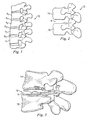
- Fig. 1 shows a lateral view of a portion of a spinal column 10, illustrating a group of adjacent upper and lower vertebrae V1, V2, V3, V4 separated by natural intervertebral discs D1, D2, D3.
- the illustration of four vertebrae is only intended as an example. Another example would be a sacrum and one vertebrae.
- the two vertebrae form a spinal segment 12 including an upper vertebrae 14 and a lower vertebrae 16.
- Some types of disc arthroplasty require that some or all of the natural disc that would have been positioned between the two vertebrae 14, 16 be removed via a discectomy or a similar surgical procedure. Removal of the diseased or degenerated disc results in the formation of an intervertebral space S between the upper and lower vertebrae 14, 16.
- FIG. 2 generally depicts the vertebral joint 12 as a lumbar vertebral joint, it is understood that the devices, systems, and methods of this disclosure may also be applied to all regions of the vertebral column, including the cervical and thoracic regions.
- Some conventional spinal prosthetic devices are installed using an anterior procedure, requiring a physician to access the spinal column using distressing and sometimes traumatic procedures. Once a prosthetic is installed using an anterior procedure, scar tissue may build on sensitive vessels. If a second procedure is required, a physician may be required to remove the scar tissue to access the previously placed prosthetic. This sensitive procedure can cause additional distress to the patient.
- the intervertebral prosthetic device disclosed herein may be advantageous over prior devices because it may be installed using a posterior procedures. Accordingly, a physician need not access and disturb the critical vessels that reside at the anterior side of the spinal column. Further, if a second procedure becomes necessary, the physician has easy access to the previously placed prosthetic without removing scar tissue off of sensitive vessels.
- Posterior implantation procedures often include removal of facet joints or processes. Because the joints and processes operate as connection locations for ligaments and muscles, their removal may limit the ability of the joint to control the degree or range of joint articulation. Accordingly, conventional prosthetic devices implanted through a posterior procedure provide articulation, but it may be largely uncontrolled. With the removal of the muscles and ligaments, the repaired joint may become floppy. The intervertebral prosthetic devices disclosed herein limit the range of articulation, thereby providing more stability and more control to the spinal column.
- Fig. 3 shows a side view of the vertebrae 14, 16 with an intervertebral prosthetic disc 18 in the disc space S.
- the disc 18 allows the vertebra 14 to articulate relative to the vertebra 16 to provide movement to the spinal joint. Sized to fit the disc space height in a manner similar to a natural intervertebral disc, such as any of discs D1-D4, the prosthetic disc 18 provides support and stabilization to the vertebrae.
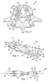
- Figs. 4-8 show a number of views of at least a portion of the prosthetic disc 18.
- Fig. 4 shows a top view of the prosthetic disc 18 in place on the vertebra 16
- Fig. 5 shows a view of the prosthetic disc 18 in place on the vertebrae 14, 16, but with the vertebrae separated to display inner features of the prosthetic disc 18.
- the prosthetic disc 18 may include a pair of prosthetic devices including a left prosthetic device 20 and a right prosthetic device 21 that cooperate together to take the place of the natural disc. While it is recognized that the prosthetic disc 18 may include more than one prosthetic device, the following description is primarily directed to only the left prosthetic device 20. It should be readily apparent that the right prosthetic device 21 of the prosthetic disc 18 may be substantially similar in structure and function to the left prosthetic device 20 and therefore will not be described in further detail.
- the prosthetic device 20 includes an upper articular portion 22 and a lower articular portion 24.
- the upper articular portion 22 includes an interdiscal section 26, a posterior section 28, and a bridge 30 extending between the interdiscal and posterior sections 26, 28.
- the lower articular portion 24 includes an interdiscal section 32, a posterior section 34, and a bridge 36 extending between the interdiscal and posterior sections 32, 34.
- the upper and lower articular portions 22, 24 may be formed of any suitably biocompatible material including metals such as cobalt-chromium alloys, titanium alloys, nickel titanium alloys, and/or stainless steel alloys. Ceramic materials such as aluminum oxide or alumina, zirconium oxide or zirconia, compact of particulate diamond, and/or pyrolytic carbon may also be suitable.
- Polymer materials may also be used, including any member of the polyaryletherketone (PAEK) family such as polyetheretherketone (PEEK), carbon-reinforced PEEK, or polyetherketoneketone (PEKK); polysulfone; polyetherimide; polyimide; ultra-high molecular weight polyethylene (UHMWPE); and/or cross-linked UHMWPE.
- PAEK polyaryletherketone
- PEEK polyetheretherketone
- PEKK polyetherketoneketone
- polysulfone polyetherimide
- polyimide polyimide
- UHMWPE ultra-high molecular weight polyethylene
- UHMWPE ultra-high molecular weight polyethylene
- the various sections comprising the upper articular portion 22 and the lower articular portion 24 may be formed of different materials thus permitting metal on metal, metal on ceramic, metal on polymer, ceramic on ceramic, ceramic on polymer, or polymer on polymer constructions.
- each of the upper and lower articular portions 22, 24 are integrally formed or molded of a single piece of material.
- one or more of the interdiscal, posterior, and bridge sections of either of the upper or lower articular portions 22, 24 may be formed separately and attached to one or more of the other sections. Attachments in these embodiments may be accomplished using any fastening mechanism known in the art including, for example, a threaded connection, a bolted connection, or a latched connection.
- the interdiscal, posterior, and bridge sections also may be formed of different materials.
- the interdiscal section 26 of the upper articular portion 22 may include a bone contacting surface 38 and an inner surface 44 opposite the bone contacting surface 38.
- a first articular surface 42 may form a part of the inner surface 44.
- the first articular surface 42 is a recess.
- the lower articular portion 24 may include a bone contacting surface 40 opposite an inner surface 48, with a second articular surface 46 forming a part of the inner surface 48 and being configured to mate with the first articular surface 42.
- the second articular surface 46 is a protrusion. Together, the first and second articular surfaces 42, 46 may form an articulating joint that allows the upper and lower articular portions 22, 24 to articulate relative to each other.
- This articulation may allow articulating movement of the upper vertebra 14 relative to the lower vertebra 16, and in some embodiments, may allow movement similar to that provided by a natural spinal disc.
- the second articular surface 46 is a partial sphere that may rotate or translate within the first articular surface 42, forming a loosely constrained ball and socket style joint.
- the first and second articular surfaces 42, 46 may be any shape or design that allows one of the upper and lower articular portions 22, 24 to move relative to the other of the upper and lower articular portions 22, 24.
- the first and second articular surfaces 42, 46 may include a trough and recess, a ball and saucer, or other shaped features.
- the interdiscal section 26 when implanted, the interdiscal section 26 may be situated along an inferior surface of the upper vertebra 14 and the interdiscal section 32 may be situated above a superior surface of the lower vertebra 16.
- the two interdiscal sections 26, 32 are not limited to such an arrangement, and may be oriented in different positions and/or shaped differently than what is illustrated herein.
- the bone contacting surfaces 38, 40 of the upper and lower articular portions 22, 24 may include features or coatings which enhance the fixation of the implanted prosthetic device 20.
- the surfaces 38, 40 may be roughened such as by chemical etching, bead-blasting, sanding, grinding, serrating, and/or diamond-cutting. All or a portion of the bone contacting surfaces 38, 40 of the upper and lower articular portions 22, 24 may also be coated with a biocompatible and osteoconductive material such as hydroxyapatite (HA), tricalcium phosphate (TCP), and/or calcium carbonate to promote bone in growth and fixation.
- HA hydroxyapatite
- TCP tricalcium phosphate
- osteoinductive coatings such as proteins from transforming growth factor (TGF) beta superfamily, or bone-morphogenic proteins, such as BMP2 or BMP7, may be used.
- TGF transforming growth factor
- BMP2 or BMP7 bone-morphogenic proteins
- suitable features may include spikes, ridges, and/or other surface textures.
- optional upper and lower bone connectors 50, 52 are formed on the bone contacting surfaces 38, 40, respectively. These bone connectors 50, 52 extend toward the upper and lower vertebrae 14, 16 in a manner to help secure the upper and lower articular portions 22, 24 in place.
- the bone connectors 50, 52 are keels configured to extend into notches or grooves formed into the vertebral endplates. Although shown as extending along a substantial length of the upper and lower articular portions, the bone connectors 50, 52 may be of any length, either shorter or longer than that shown, and in addition, may have some other orientation or features other than that shown.
- the bone connectors are a series of ridges, protrusions, or other surface features that help fix the prosthetic device 20 in place.
- the upper articular portion 22 also includes additional features for affixing to the vertebrae 14.
- the upper articular portion 22 includes a connecting aperture 54 (best seen in Figs. 6 and 7 ) configured to receive a bone fastener 56 (shown in Figs. 3 and 4 ), such as a screw.
- the connecting aperture 54 may be disposed adjacent a rear of the interdiscal section 26 so that the bone fastener 56 may be driven through the aperture 54 into the rear of the vertebral body of the vertebra 14.
- the connecting aperture 54 may be disposed elsewhere so long as the bone fastener 56 in the aperture 54 may help hold the prosthetic device 20 in place.
- the lower articular portion 24 does not include a connecting aperture. However, in other embodiments, one or more connecting apertures may be included.
- the bridge sections 30, 36 extend rearward from the interdiscal sections 26, 32 respectively. In the embodiment shown, the bridge sections 30, 36 extend substantially along a longitudinal centerline 58 ( Fig. 7 ) of the prosthetic device 20. In other embodiments, the bridge sections do not align with a longitudinal centerline of the interdiscal sections, but may be curved or angled to depart away from the longitudinal centerline.
- the posterior sections 28, 34 may be disposed at the end of the bridge sections 30, 36 and may be configured to fit adjacent to the processes of the vertebrae 14, 16.
- the posterior section 34 of the lower articular portion 24 may include a post 60 having a bridge end 62 and a tail end 64.
- the post 60 may be configured to extend generally in a direction along the spinal column.
- the bridge end 62 of the post 60 may connect to the bridge section 36.
- the bridge end 62 of the post 60 is formed by a bend in the bridge section 36, and includes a depression 65 that dips below the level of the bridge section 36.
- the post 60 may extend upwardly so that the tail end 64 of the post 60 may be disposed at a location higher than the bridge section 36.
- the tail end 64 may include a motion stop 66 configured to limit the range of articulation between the upper and lower articular portions 22, 24.
- the motion stop 66 is a bend in the post. 60 having a length that is configured to work together with the upper articular portion 22 to limit the available range of articular rotation of the upper and lower articular portions 22, 24.
- the post 60 may include a straight segment extending between the bridge end 62 and the tail end 64.
- the post 60 may include a curve concentric with the curvature of the protruding articular surface 46.
- the posterior section 28 of the upper articular portion 22 includes a tab 68 having an aperture 70 formed therein that is configured to receive the post 60 of the lower articular portion 24.
- the aperture 70 is a rectangular shaped hole having a width w ( Fig. 7 ) that is less than the length of the tail end 64.
- a portion of the tab 68 forms a motion stop 69 that is configured to cooperate with the motion stop 66 on the post 60. Accordingly, when the upper and lower articular portions 22, 24 are assembled as shown in Fig. 6 , the motion stop 66 and the motion stop 69 cooperate to limit the range of articulation of the prosthetic device 20.
- the aperture 70 is configured so that when the articulating surfaces 42, 46 are mated, the post 60 extends through the aperture 70 in a manner that articulation may still freely occur within the range.
- the upper and lower articular portions 22, 24 may be configured for assembly outside of the disc space S of Fig. 2 .
- the upper articular portion 22 may be placed on the lower articular portion 24 when the upper and lower articular portions 22, 24 are outside the disc space S.
- the upper and lower articular portions 22, 24 may be difficult to disassemble within the disc space S. Therefore, the chance of the upper and lower articular portions 22, 24 becoming misaligned after implantation is virtually eliminated.
- the post 60 and aperture 70 reduce axial rotation of one of the upper and lower articular portions 22, 24 about the other of the upper and lower articular portions 22, 24. Accordingly, despite forming a ball and socket joint, the upper and lower articular portions 22, 24 are bound together so that axial rotation is limited to by the size of the aperture 70 and the post 60.
- Figs. 4 and 7 are top views of the prosthetic device 20.
- the post 60 and aperture 70 while still aligned along the longitudinal centerline 58, are also rotated. Accordingly, the tail end 64 is turned to point in a direction offset from the longitudinal centerline 58.
- the rectangular or square aperture 70 is angled to match the angle of the tail end 64. In the embodiment shown, the angle is formed in the posterior section 34 of the lower articular portion 24, and not in the bridge section 36 of the lower articular portion 24. As seen best in Fig.
- this angle may assist in fitting the prosthetic device 20 within the intervertebral space S by allowing the tail end to extend substantially rearward although the bridge sections and intervertebral disc sections extend into the intervertebral space S at an angle.
- the right prosthetic device 21 includes a similar angled posterior end, but is angled in a direction opposite that of the left prosthetic device 20.
- the posterior sections are not angled at all, while in others the bridge sections are angled or turned.
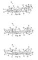
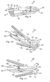
- Figs. 8a-8c show one example of an articulation range of the articulating prosthetic device 20.
- Fig. 8a shows the prosthetic device 20 articulated to a first limit
- Fig. 8b shows the prosthetic device 20 articulated to a central position
- Fig. 8c shows the prosthetic device 20 articulated to a second limit.
- the motion stop 69 on the posterior section 34 of the upper articular portion 22 is in contact with the motion stop 66 of the lower articular portion 24. Accordingly, a flexion/extension and/or torsional articulation range of the prosthetic device 20 is limited to the amount allowed by the motion stops 66 and 69.
- Fig. 8a shows the prosthetic device 20 articulated to a first limit
- Fig. 8b shows the prosthetic device 20 articulated to a central position
- Fig. 8c shows the prosthetic device 20 articulated to a second limit.
- the motion stop 69 on the posterior section 34 of the upper articular portion 22 is in contact with the
- Fig. 8b shows the prosthetic device 20 articulated to a substantially central position, with the aperture 70 being disposed about the middle region of the post 60.
- Fig. 8c shows the prosthetic device 20 articulated to the second limit.
- the bridge sections 30, 36 act as motion stops to limit the articulation between the upper and lower articular portions 22, 24.
- the total range of motion, represented by Fig. 8a to 8c may be about 45 degrees: However, the range of motion could be more or less than this, as controlled by the motion stops.
- Fig. 9 shows an alternate embodiment of an articulating device.
- a biasing member 72 is disposed about the post 60.
- muscles and ligaments supporting the vertebrae may be disconnected from the facet joints, and the facet joints may be removed. Accordingly, implanting an articular device may allow unrestrained movement within the range of motion.
- the biasing member 72 in Fig. 9 may bias the prosthetic device 20 to a desired position, such as a neutral position. Accordingly, although some or all the muscles and ligaments that control the articulation of a healthy spinal disc are removed, the biasing member 72 may provide a stabilizing force that controls the articular movement.
- the biasing member 72 is one or more springs disposed about the post 60 both above and below the posterior section 28 of the upper articular portion 22. This may provide dampening in both flexion and tension.
- the biasing member is a elastomeric member.
- the biasing member may be, for example, a friction element, an extendable band, or a bumper, such as a urethane bumper.
- the biasing member 72 is disposed only above or only below the posterior section 28 of the upper articular portion 22.
- the biasing member is disposed elsewhere, such as on the bridge sections 30, 36.
- the biasing member may provide some torsional resistance to the articular device.
- the articular prosthetic device 100 may have many features similar to the articular prosthetic device 20 described above. A description of these features will not be repeated here in detail.
- the articular prosthetic device 100 includes an upper articular portion 102 and a lower articular portion 104, each having an interdiscal section 106, 108, respectively.
- the interdiscal sections 106, 108 define a longitudinal centerline 109.
- a first connecting aperture 110 on the upper articular portion 102 is configured to allow introduction of a bone fastener 112, such as a screw, in a direction that is substantially aligned with the longitudinal centerline 109 ( Fig.
- a second connecting aperture 114 on the lower articular portion 104 is configured to allow introduction of a bone fastener 116 in a direction that is substantially aligned with the longitudinal centerline 109 of the articular prosthetic device 100 so that the fastener 116 and the longitudinal centerline 109 may lie substantially within the same plane.
- any screws are driven into bone at an angle offset from the longitudinal centerline.
- the device may be displaced and may move from its initial, set position. Displacement often occurs in the direction of the screw. Accordingly, if the direction of the screw is offset from the longitudinal centerline of the device, then when driven into the bone, the screw often displaces the device in a direction offset from the longitudinal centerline. This movement can create alignment discrepancies between the top and bottom articulating portions.
- the articular prosthetic device 100 is configured so that both the first and second connecting apertures 110, 114 are configured to align the respective fasteners 112, 116 so that the longitudinal centerline 109 and the fasteners 112, 116 lie substantially within the same plane. Accordingly, when the fasteners 112, 116 draw the prosthetic device 100 tight against the bone, any movement or displacement of the prosthetic device 100 from its position is in the direction of the longitudinal centerline. Accordingly, the prosthetic device 100 may be better aligned and may sit closer to the actual desired location.
- the articular prosthetic device 100 also is designed to be versatile and fit in either a right or left side of the vertebral space S. Accordingly, a physician need not determine whether the prosthetic devices 100 is a left or a right device. This simplifies the surgical procedure and reduces chance of error. Further, a single prosthetic device usable for both the right and left sides may reduce and simplify manufacturing costs because only one design is required, rather than two. It should be noted, however, that the disclosed features may be included on symmetric devices, such as devices designed for use in either a left or right position, or on asymmetric devices, such as devices designed for use in one of a left and a right position.
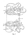
- the prosthetic device 100 of Figs. 10-15 includes a posterior section 118 of the lower articular portion 104 having an upwardly extending post 120.
- the post 120 is disposed along the centerline 109 and includes a motion stop 122 that cooperates with a posterior section 124 of the upper articular portion 102 to limit the range of articulation.
- the post 120 includes an aperture 126 extending therethrough that provides access to the first connecting aperture 110 in the upper articular portion 102.
- the second connecting aperture 114 is disposed in a lower portion of the post 120 and therefore can be easily accessed from the posterior side.
- the posterior section 124 of the upper articular portion 102 includes a first extending arm 128 and a second extending arm 130.
- the arms 128, 130 extend around the post 120 so that the post is constrained from both lateral movement and from displacement along the centerline 109. Adjacent the post 120, the arms 128, 130 include motion stops 132 configured to contact the motion stop 122 on the post 120.
- the arms 128, 130 of the prosthetic device 100 do not connect to form a closed aperture through which the post extends. Instead, the arms 132 with the motion stops 132 do not connect, leaving a centrally disposed gap 134.
- the gap 134 in the posterior section of the upper articular portion 102 of the prosthetic device 100 is aligned with the aperture 126 in the post 120 to provide access to the connecting aperture 110 of the upper articular portion 102 of the prosthetic device 100, as shown in Fig. 15 .
- the second connecting aperture 114 may be formed in the lower articular portion 104, and may be formed at the first end of the post 120. Accordingly, the first and second connecting apertures 110, 114 are not horizontally aligned, but are horizontally offset.
- the upper connecting aperture 110 is disposed so that the fastener 112 enters the rear of the anterior arch of the vertebra 14.
- the lower connecting aperture 114 is disposed so that the fastener 116 enters the pedicle and passes into the anterior arch of the lower vertebra 16. It should be noted that in other embodiments, the connecting apertures 110, 114 may horizontally aligned, and additionally, in other embodiments, the connecting aperture 114 may be disposed at any location adjacent to or between the post 120 and the articular portions. One example of this is shown with reference to an artificial intervertebral joint 100' in Fig. 16 . All the features discussed with respect to the artificial intervertebral joint 100 also may be applicable to the artificial intervertebral joint 100'. The artificial intervertebral joint 100 may be installed between the vertebrae 14, 16 as will be described below.
- the artificial intervertebral prosthetic device 20 may be implanted into a body using a posterior transforaminal approach similar to the known transforaminal lumbar interbody fusion (TLIF) or posterior lumbar interbody fusion (PLIF) procedures.
- TLIF transforaminal lumbar interbody fusion
- PLIF posterior lumbar interbody fusion
- TLIF approaches are typically more oblique, requiring less retraction of the exiting root, and less epidural bleeding with less retraction of the traversing structures. It is also possible to access the interspace using a far lateral approach. In some instances it is possible to access the interspace via the far lateral without resecting the facets.
- an incision such as a midline incision, may be made in the patient's back and some or all of the affected disc and surrounding tissue may be removed via the foramina.
- the superior endplate surface of the vertebra 14 may be milled, rasped, or otherwise resected to match the profile of the bone contacting surface 38 of the upper articular surface 22, to normalize stress distributions on the superior endplate surface of the vertebra 14, and/or to provide initial fixation prior to bone ingrowth.
- the preparation of the endplate of vertebra 14 may result in a flattened surface or in surface contours such as pockets, grooves, or other contours that may match corresponding features on the bone contacting surface 38.
- the inferior endplate of the vertebra 16 may be similarly prepared to receive the lower articular portion 24 to the extent allowed by the exiting nerve root and the dorsal root ganglia. In some procedures, the natural facet joints of vertebrae 14, 16 may be trimmed or removed to make room for the posterior component 120.
- the upper and lower articular portions 22, 24 of the prosthetic device 20 may then be oriented so that the post 60 is extending through the aperture 70. Or with reference to the prosthetic device 1.00, so that the post 120 is extending between the two arms 128, 130.
- the upper and lower articular portions then may be simultaneously introduced into the transforaminal openings and are placed in the appropriate intervertebral disc space between the upper and lower vertebrae. In some procedures, because of the compact nature of the post and aperture (or post and arms), the upper and lower articular portions may be introduced through a cannula. If the pieces are modular, the prosthetic device may be implanted pieces at a time, with posterior sections of the upper and lower articular portions introduced last.
- the bridge sections 30,36 may extend in a posterior direction from the interdiscal sections 26, 32 and in a posterior direction from the intervertebral disc space S.
- the posterior sections 28, 34 are positioned in a posterior direction of the intervertebral disc space to replace or supplement the function of the natural facet joints.
- the fastener 56 may be inserted through the connecting aperture 58 into the upper vertebra 14.
- the fastener 112 may be introduced through the gap 134 and the aperture 126 in the posterior sections, through the aperture 110, and into the upper vertebra 14.
- the fastener. 116 may be inserted through the connecting aperture 114 in the posterior section 118 of the lower articular portion 104 and into adjacent bone such as the pedicle of the vertebra 16.
- the ball and socket type joint created by the articular surfaces 42, 46 may be relatively stable and self-centering. Both the anterior joint and the posterior connection (formed by the post and aperture connection) allow the prosthetic device 20 to resist shear forces, particularly anterior-posterior forces. Further, rotational motion about a longitudinal centerline defined by the cylindrical bodies 14, 16 may be limited both by the constraint in the post and aperture connection and by the combined constraint provided by the two prosthetic devices 20, 21.
- the robust and forgiving structure of the anterior joint and the post and aperture connection permits misalignment and slight inaccuracy in the placement of the prosthetic devices 20, 21.
- the ball and socket structure of the articular joint tolerates a certain amount of misalignment between the components.
- the Interaction of the post and aperture may also accommodate parallel misalignment and/or anterior-posterior misalignment between the prosthetic devices 20, 21.
- a single unilateral prosthetic device may be implanted, while in others, two devices, forming a right and a left device may be implanted.
- a three-piece articulating disc may be used instead of only upper and lower articulating portions that provide articulation.
- a third articulating component may be disposed between the upper and lower articulating portions to provide articulation.
Abstract
Description
- Disc arthroplasty is one way of treating injured, degraded, or diseased spinal discs. Some disc arthroplasty treatments include replacing injured discs of the joint with a motion-preserving spinal disc that allows some articulation or movement of the spinal joint. While the inserted disc may provide joint articulation to a patient, inserting the spinal disc can be an invasive and intensive procedure. For example, anterior procedures often require displacement of organs, such as the aorta and vena cava, and must be performed with great care. Further, because scar tissue may grow about the surgical site, any required second treatment can be more difficult, and may introduce additional distress to the patient.
- What is needed is a prosthetic device for insertion into an intervertebral space that may be installed from a posterior position. The posterior joint replacement device disclosed herein overcomes one or more problems in the prior art.
-
US 2005/0171610 discloses Several intervertebral prosthetic devices with articulating components and posterior sections which extend posteriorly from the intervertebral space when the device is in-situ. In one embodiment posterior sections are directly attached to the adjacent vertebral body via a pedicle screw. The pedicle screws may be connected to each other by tension bands. In another embodiment the posterior portions rock freely relative to each other. -
US 2005/0256578 discloses an intervertebral prosthetic device with posterior portions comprising a locking arrangement with two oblique struts, two locking bars, or posts, in which each bar is arranged to oppose the other at fixed surfaces held within an outers sleeve. - The invention is directed to a prosthetic device for posterior placement in an intervertebral space defined between an upper vertebrae and a lower vertebrae to provide articulating motion to the upper and lower vertebrae. The device includes an upper articular portion configured to be at least partially disposed in the intervertebral space. It also includes a lower articular portion configured to be at least partially disposed in the intervertebral space below the upper articular portion.
- The upper and lower articular portions are configured to provide articulating motion to the upper and lower vertebrae.
- The upper and lower articular portions each include a posterior section configured to be disposed in a location posterior of the intervertebral space. The posterior section of one of the upper and lower articular portions includes a post, and the posterior section of the other of the upper and lower articular portions includes a receiving portion configured to interact with the post during articulation.
- The receiving post is an aperture and the post is extending through this aperture.
- In another aspect, at least one connecting hole may be associated with at least one of the upper and lower articular portions. The at least one of the upper and lower articular portions may define a longitudinal centerline and the at least one connecting hole may be aligned along the centerline.
- In another exemplary aspect, this disclosure is directed toward a joint replacement device for placement in an intervertebral space defined between an upper vertebrae and a lower vertebrae to provide articulating motion to the upper and lower vertebrae. The joint replacement device may include a first joint replacement device and a second join replacement device. The first and the second joint replacement devices each may include an upper articular device configured to be at least partially disposed in the intervertebral space and a lower articular device configured to be at least partially disposed in the intervertebral space. The upper and lower articular device may be configured to provide articulated motion to the upper and lower vertebrae. The upper and lower articular devices each may have a centerline and a screw port aligned along the centerline.
- In yet another exemplary aspect, this disclosure is directed to a joint replacement device for placement in an intervertebral space defined between an upper vertebrae and a lower vertebrae to provide articulating motion to the upper and lower vertebrae. The joint replacement device may include a first joint replacement device configured to be implanted at least partially within the intervertebral disc space and a second joint replacement device configured to be implanted at least partially within the intervertebral disc space adjacent the first joint replacement device. The first and the second joint replacement devices may be substantially identical so that each can be implanted on either of a right side or the left side of the intervertebral disc space.
-
-
Fig. 1 is a pictorial representation of a lateral view of a portion of a vertebral column. -
Fig. 2 is a pictorial representation of a lateral view of a pair of adjacent vertebral bodies defining an intervertebral space. -
Fig. 3 is a pictorial representation of an intervertebral prosthetic device disposed between adjacent vertebral bodies. -
Fig. 4 is a pictorial representation of a top view of an intervertebral prosthetic device on a lower vertebral body. -
Fig. 5 is a pictorial representation showing inner features of an intervertebral prosthetic device between vertebral bodies. -
Figs. 6, 7 , and8a-8c are pictorial representations of an intervertebral prosthetic device. -
Fig. 9 is a pictorial representation of an intervertebral prosthetic device including a biasing member. -
Figs. 10-12 are pictorial representations of an intervertebral prosthetic device according to another aspect. -
Figs. 13-15 are pictorial representations of the intervertebral prosthetic device ofFigs. 10-12 disposed between vertebral bodies. -
Fig. 16 is a pictorial representation of an intervertebral prosthetic device according to another aspect of the device shown inFigs. 10-12 . - The present invention relates generally to vertebral reconstructive devices and, more particularly, to an intervertebral prosthetic device for implantation. For the purposes of promoting and understanding of the principles of the invention, reference will now be made to embodiments or examples illustrated in the drawings and specific language will be used to describe the same.
-
Fig. 1 shows a lateral view of a portion of aspinal column 10, illustrating a group of adjacent upper and lower vertebrae V1, V2, V3, V4 separated by natural intervertebral discs D1, D2, D3. The illustration of four vertebrae is only intended as an example. Another example would be a sacrum and one vertebrae. - For the sake of further example, two of the vertebrae will be discussed with reference to
Fig. 2 . The two vertebrae form aspinal segment 12 including anupper vertebrae 14 and alower vertebrae 16. Some types of disc arthroplasty require that some or all of the natural disc that would have been positioned between the twovertebrae lower vertebrae Fig. 2 generally depicts thevertebral joint 12 as a lumbar vertebral joint, it is understood that the devices, systems, and methods of this disclosure may also be applied to all regions of the vertebral column, including the cervical and thoracic regions. - Some conventional spinal prosthetic devices are installed using an anterior procedure, requiring a physician to access the spinal column using distressing and sometimes traumatic procedures. Once a prosthetic is installed using an anterior procedure, scar tissue may build on sensitive vessels. If a second procedure is required, a physician may be required to remove the scar tissue to access the previously placed prosthetic. This sensitive procedure can cause additional distress to the patient. The intervertebral prosthetic device disclosed herein may be advantageous over prior devices because it may be installed using a posterior procedures. Accordingly, a physician need not access and disturb the critical vessels that reside at the anterior side of the spinal column. Further, if a second procedure becomes necessary, the physician has easy access to the previously placed prosthetic without removing scar tissue off of sensitive vessels. Accordingly, the procedure may be simplified and may cause less distress to the patient. Posterior implantation procedures often include removal of facet joints or processes. Because the joints and processes operate as connection locations for ligaments and muscles, their removal may limit the ability of the joint to control the degree or range of joint articulation. Accordingly, conventional prosthetic devices implanted through a posterior procedure provide articulation, but it may be largely uncontrolled. With the removal of the muscles and ligaments, the repaired joint may become floppy. The intervertebral prosthetic devices disclosed herein limit the range of articulation, thereby providing more stability and more control to the spinal column.
-
Fig. 3 shows a side view of thevertebrae intervertebral prosthetic disc 18 in the disc space S. Thedisc 18 allows thevertebra 14 to articulate relative to thevertebra 16 to provide movement to the spinal joint. Sized to fit the disc space height in a manner similar to a natural intervertebral disc, such as any of discs D1-D4, theprosthetic disc 18 provides support and stabilization to the vertebrae. -
Figs. 4-8 show a number of views of at least a portion of theprosthetic disc 18.Fig. 4 shows a top view of theprosthetic disc 18 in place on thevertebra 16, andFig. 5 shows a view of theprosthetic disc 18 in place on thevertebrae prosthetic disc 18. With reference to -
Fig. 4 , theprosthetic disc 18 may include a pair of prosthetic devices including a leftprosthetic device 20 and a rightprosthetic device 21 that cooperate together to take the place of the natural disc. While it is recognized that theprosthetic disc 18 may include more than one prosthetic device, the following description is primarily directed to only the leftprosthetic device 20. It should be readily apparent that the rightprosthetic device 21 of theprosthetic disc 18 may be substantially similar in structure and function to the leftprosthetic device 20 and therefore will not be described in further detail. - With reference to
Fig. 4-8 , theprosthetic device 20 includes an upperarticular portion 22 and a lowerarticular portion 24. The upperarticular portion 22 includes aninterdiscal section 26, aposterior section 28, and abridge 30 extending between the interdiscal andposterior sections articular portion 24 includes aninterdiscal section 32, aposterior section 34, and abridge 36 extending between the interdiscal andposterior sections - The upper and lower
articular portions articular portion 22 and the lowerarticular portion 24 may be formed of different materials thus permitting metal on metal, metal on ceramic, metal on polymer, ceramic on ceramic, ceramic on polymer, or polymer on polymer constructions. - In the exemplary embodiment shown, each of the upper and lower
articular portions articular portions - The
interdiscal section 26 of the upperarticular portion 22 may include abone contacting surface 38 and aninner surface 44 opposite thebone contacting surface 38. A first articular surface 42 may form a part of theinner surface 44. In the embodiment shown, the first articular surface 42 is a recess. Similarly, the lowerarticular portion 24 may include abone contacting surface 40 opposite aninner surface 48, with a secondarticular surface 46 forming a part of theinner surface 48 and being configured to mate with the first articular surface 42. In the embodiment shown, the secondarticular surface 46 is a protrusion. Together, the first and secondarticular surfaces 42, 46 may form an articulating joint that allows the upper and lowerarticular portions upper vertebra 14 relative to thelower vertebra 16, and in some embodiments, may allow movement similar to that provided by a natural spinal disc. In the embodiment shown, the secondarticular surface 46 is a partial sphere that may rotate or translate within the first articular surface 42, forming a loosely constrained ball and socket style joint. Although shown as a ball and socket joint, the first and secondarticular surfaces 42, 46 may be any shape or design that allows one of the upper and lowerarticular portions articular portions articular surfaces 42, 46 may include a trough and recess, a ball and saucer, or other shaped features. - As shown in
Fig. 5 , when implanted, theinterdiscal section 26 may be situated along an inferior surface of theupper vertebra 14 and theinterdiscal section 32 may be situated above a superior surface of thelower vertebra 16. However, it should be understood by one of ordinary skill in the art that the twointerdiscal sections - The
bone contacting surfaces articular portions prosthetic device 20. For example, thesurfaces bone contacting surfaces articular portions - In the exemplary embodiment shown, optional upper and
lower bone connectors bone contacting surfaces bone connectors lower vertebrae articular portions bone connectors bone connectors prosthetic device 20 in place. - In the embodiment shown, the upper
articular portion 22 also includes additional features for affixing to thevertebrae 14. For example, the upperarticular portion 22 includes a connecting aperture 54 (best seen inFigs. 6 and 7 ) configured to receive a bone fastener 56 (shown inFigs. 3 and4 ), such as a screw. The connectingaperture 54 may be disposed adjacent a rear of theinterdiscal section 26 so that thebone fastener 56 may be driven through theaperture 54 into the rear of the vertebral body of thevertebra 14. In other embodiments, the connectingaperture 54 may be disposed elsewhere so long as thebone fastener 56 in theaperture 54 may help hold theprosthetic device 20 in place. In the embodiment shown, the lowerarticular portion 24 does not include a connecting aperture. However, in other embodiments, one or more connecting apertures may be included. - The
bridge sections interdiscal sections bridge sections Fig. 7 ) of theprosthetic device 20. In other embodiments, the bridge sections do not align with a longitudinal centerline of the interdiscal sections, but may be curved or angled to depart away from the longitudinal centerline. - The
posterior sections bridge sections vertebrae posterior section 34 of the lowerarticular portion 24 may include apost 60 having abridge end 62 and atail end 64. Thepost 60 may be configured to extend generally in a direction along the spinal column. - The
bridge end 62 of thepost 60 may connect to thebridge section 36. In the example shown, thebridge end 62 of thepost 60 is formed by a bend in thebridge section 36, and includes adepression 65 that dips below the level of thebridge section 36. Thepost 60 may extend upwardly so that thetail end 64 of thepost 60 may be disposed at a location higher than thebridge section 36. Thetail end 64 may include amotion stop 66 configured to limit the range of articulation between the upper and lowerarticular portions motion stop 66 is a bend in the post. 60 having a length that is configured to work together with the upperarticular portion 22 to limit the available range of articular rotation of the upper and lowerarticular portions post 60 may include a straight segment extending between thebridge end 62 and thetail end 64. In one exemplary embodiment, thepost 60 may include a curve concentric with the curvature of the protrudingarticular surface 46. - The
posterior section 28 of the upperarticular portion 22 includes atab 68 having anaperture 70 formed therein that is configured to receive thepost 60 of the lowerarticular portion 24. In the embodiment shown, theaperture 70 is a rectangular shaped hole having a width w (Fig. 7 ) that is less than the length of thetail end 64. A portion of thetab 68 forms amotion stop 69 that is configured to cooperate with themotion stop 66 on thepost 60. Accordingly, when the upper and lowerarticular portions Fig. 6 , themotion stop 66 and themotion stop 69 cooperate to limit the range of articulation of theprosthetic device 20. In addition, theaperture 70 is configured so that when the articulatingsurfaces 42, 46 are mated, thepost 60 extends through theaperture 70 in a manner that articulation may still freely occur within the range. - Because of the bend in the
tail end 64 forming themotion stop 66, the upper and lowerarticular portions Fig. 2 . For example, the upperarticular portion 22 may be placed on the lowerarticular portion 24 when the upper and lowerarticular portions articular portions articular portions post 60 andaperture 70 reduce axial rotation of one of the upper and lowerarticular portions articular portions articular portions aperture 70 and thepost 60. -
Figs. 4 and 7 are top views of theprosthetic device 20. As apparent in these views, thepost 60 andaperture 70, while still aligned along the longitudinal centerline 58, are also rotated. Accordingly, thetail end 64 is turned to point in a direction offset from the longitudinal centerline 58. Likewise, the rectangular orsquare aperture 70 is angled to match the angle of thetail end 64. In the embodiment shown, the angle is formed in theposterior section 34 of the lowerarticular portion 24, and not in thebridge section 36 of the lowerarticular portion 24. As seen best inFig. 4 , this angle may assist in fitting theprosthetic device 20 within the intervertebral space S by allowing the tail end to extend substantially rearward although the bridge sections and intervertebral disc sections extend into the intervertebral space S at an angle. As shown inFig. 4 , the rightprosthetic device 21 includes a similar angled posterior end, but is angled in a direction opposite that of the leftprosthetic device 20. In some embodiments, the posterior sections are not angled at all, while in others the bridge sections are angled or turned. -
Figs. 8a-8c show one example of an articulation range of the articulatingprosthetic device 20.Fig. 8a shows theprosthetic device 20 articulated to a first limit,Fig. 8b shows theprosthetic device 20 articulated to a central position, andFig. 8c shows theprosthetic device 20 articulated to a second limit. At the first limit inFig. 8a , themotion stop 69 on theposterior section 34 of the upperarticular portion 22 is in contact with themotion stop 66 of the lowerarticular portion 24. Accordingly, a flexion/extension and/or torsional articulation range of theprosthetic device 20 is limited to the amount allowed by the motion stops 66 and 69.Fig. 8b shows theprosthetic device 20 articulated to a substantially central position, with theaperture 70 being disposed about the middle region of thepost 60.Fig. 8c shows theprosthetic device 20 articulated to the second limit. At the second limit, thebridge sections articular portions Fig. 8a to 8c may be about 45 degrees: However, the range of motion could be more or less than this, as controlled by the motion stops. -
Fig. 9 shows an alternate embodiment of an articulating device. InFig. 9 , a biasingmember 72 is disposed about thepost 60. As discussed above, in posterior procedures, muscles and ligaments supporting the vertebrae may be disconnected from the facet joints, and the facet joints may be removed. Accordingly, implanting an articular device may allow unrestrained movement within the range of motion. To limit the undesirable ranges of motion, the biasingmember 72 inFig. 9 may bias theprosthetic device 20 to a desired position, such as a neutral position. Accordingly, although some or all the muscles and ligaments that control the articulation of a healthy spinal disc are removed, the biasingmember 72 may provide a stabilizing force that controls the articular movement. In one example, the biasingmember 72 is one or more springs disposed about thepost 60 both above and below theposterior section 28 of the upperarticular portion 22. This may provide dampening in both flexion and tension. In another embodiment, the biasing member is a elastomeric member. In yet other embodiments, the biasing member may be, for example, a friction element, an extendable band, or a bumper, such as a urethane bumper. In some embodiments, rather than being disposed both above and below theposterior section 28 of the upperarticular portion 22, the biasingmember 72 is disposed only above or only below theposterior section 28 of the upperarticular portion 22. In other embodiments, the biasing member is disposed elsewhere, such as on thebridge sections - Another embodiment of an articular
prosthetic device 100 is shown inFigs. 10-16 . The articularprosthetic device 100 may have many features similar to the articularprosthetic device 20 described above. A description of these features will not be repeated here in detail. The articularprosthetic device 100 includes an upperarticular portion 102 and a lowerarticular portion 104, each having aninterdiscal section interdiscal sections longitudinal centerline 109. A first connectingaperture 110 on the upperarticular portion 102 is configured to allow introduction of abone fastener 112, such as a screw, in a direction that is substantially aligned with the longitudinal centerline 109 (Fig. 12 ) of the articularprosthetic device 100, so that thefastener 112 and thelongitudinal centerline 109 may lie substantially within the same plane. Similarly, a second connectingaperture 114 on the lowerarticular portion 104 is configured to allow introduction of abone fastener 116 in a direction that is substantially aligned with thelongitudinal centerline 109 of the articularprosthetic device 100 so that thefastener 116 and thelongitudinal centerline 109 may lie substantially within the same plane. - In a conventional prosthetic disc, any screws are driven into bone at an angle offset from the longitudinal centerline. As the screws are tightened, drawing the device against the bone, the device may be displaced and may move from its initial, set position. Displacement often occurs in the direction of the screw. Accordingly, if the direction of the screw is offset from the longitudinal centerline of the device, then when driven into the bone, the screw often displaces the device in a direction offset from the longitudinal centerline. This movement can create alignment discrepancies between the top and bottom articulating portions.
- To assist in securing it in place, the articular
prosthetic device 100 is configured so that both the first and second connectingapertures respective fasteners longitudinal centerline 109 and thefasteners fasteners prosthetic device 100 tight against the bone, any movement or displacement of theprosthetic device 100 from its position is in the direction of the longitudinal centerline. Accordingly, theprosthetic device 100 may be better aligned and may sit closer to the actual desired location. - The articular
prosthetic device 100 also is designed to be versatile and fit in either a right or left side of the vertebral space S. Accordingly, a physician need not determine whether theprosthetic devices 100 is a left or a right device. This simplifies the surgical procedure and reduces chance of error. Further, a single prosthetic device usable for both the right and left sides may reduce and simplify manufacturing costs because only one design is required, rather than two. It should be noted, however, that the disclosed features may be included on symmetric devices, such as devices designed for use in either a left or right position, or on asymmetric devices, such as devices designed for use in one of a left and a right position. - Like the
prosthetic device 20 described above, theprosthetic device 100 ofFigs. 10-15 includes aposterior section 118 of the lowerarticular portion 104 having an upwardly extendingpost 120. Thepost 120 is disposed along thecenterline 109 and includes a motion stop 122 that cooperates with aposterior section 124 of the upperarticular portion 102 to limit the range of articulation. In this embodiment, thepost 120 includes anaperture 126 extending therethrough that provides access to the first connectingaperture 110 in the upperarticular portion 102. As shown inFig. 15 , the second connectingaperture 114 is disposed in a lower portion of thepost 120 and therefore can be easily accessed from the posterior side. - The
posterior section 124 of the upperarticular portion 102 includes a first extendingarm 128 and a second extendingarm 130. Thearms post 120 so that the post is constrained from both lateral movement and from displacement along thecenterline 109. Adjacent thepost 120, thearms post 120. Unlike theprosthetic device 20 described above, thearms prosthetic device 100 do not connect to form a closed aperture through which the post extends. Instead, thearms 132 with the motion stops 132 do not connect, leaving a centrally disposedgap 134. Thegap 134 in the posterior section of the upperarticular portion 102 of theprosthetic device 100 is aligned with theaperture 126 in thepost 120 to provide access to the connectingaperture 110 of the upperarticular portion 102 of theprosthetic device 100, as shown inFig. 15 . With reference toFig. 11 , the second connectingaperture 114 may be formed in the lowerarticular portion 104, and may be formed at the first end of thepost 120. Accordingly, the first and second connectingapertures aperture 110 is disposed so that thefastener 112 enters the rear of the anterior arch of thevertebra 14. The lower connectingaperture 114 is disposed so that thefastener 116 enters the pedicle and passes into the anterior arch of thelower vertebra 16. It should be noted that in other embodiments, the connectingapertures aperture 114 may be disposed at any location adjacent to or between thepost 120 and the articular portions. One example of this is shown with reference to an artificial intervertebral joint 100' inFig. 16 . All the features discussed with respect to the artificial intervertebral joint 100 also may be applicable to the artificial intervertebral joint 100'. The artificial intervertebral joint 100 may be installed between thevertebrae prosthetic device 20, it is understood that the rightprosthetic device 21 may be installed in a similar manner. Further, it is understood that theprosthetic device 100 also may be installed in a similar manner. Generally, as discussed above, the artificial intervertebralprosthetic device 20 may be implanted into a body using a posterior transforaminal approach similar to the known transforaminal lumbar interbody fusion (TLIF) or posterior lumbar interbody fusion (PLIF) procedures. PLIF approaches are generally more medial and rely on more retraction of the traversing root and dura to access the vertebral interspace. TLIF approaches are typically more oblique, requiring less retraction of the exiting root, and less epidural bleeding with less retraction of the traversing structures. It is also possible to access the interspace using a far lateral approach. In some instances it is possible to access the interspace via the far lateral without resecting the facets. - Furthermore, a direct lateral approach through the psoas is known. This approach avoids the posterior neural elements completely. It is anticipated that embodiments of the
prosthetic devices - According to at least one of these approaches, an incision, such as a midline incision, may be made in the patient's back and some or all of the affected disc and surrounding tissue may be removed via the foramina. The superior endplate surface of the
vertebra 14 may be milled, rasped, or otherwise resected to match the profile of thebone contacting surface 38 of the upperarticular surface 22, to normalize stress distributions on the superior endplate surface of thevertebra 14, and/or to provide initial fixation prior to bone ingrowth. The preparation of the endplate ofvertebra 14 may result in a flattened surface or in surface contours such as pockets, grooves, or other contours that may match corresponding features on thebone contacting surface 38. The inferior endplate of thevertebra 16 may be similarly prepared to receive the lowerarticular portion 24 to the extent allowed by the exiting nerve root and the dorsal root ganglia. In some procedures, the natural facet joints ofvertebrae posterior component 120. - The upper and lower
articular portions prosthetic device 20 may then be oriented so that thepost 60 is extending through theaperture 70. Or with reference to the prosthetic device 1.00, so that thepost 120 is extending between the twoarms bridge sections interdiscal sections posterior sections - Referring to the
prosthetic device 20, thefastener 56 may be inserted through the connecting aperture 58 into theupper vertebra 14. Referring to theprosthetic device 100, thefastener 112 may be introduced through thegap 134 and theaperture 126 in the posterior sections, through theaperture 110, and into theupper vertebra 14. Likewise, the fastener. 116 may be inserted through the connectingaperture 114 in theposterior section 118 of the lowerarticular portion 104 and into adjacent bone such as the pedicle of thevertebra 16. - As installed, the ball and socket type joint created by the
articular surfaces 42, 46 may be relatively stable and self-centering. Both the anterior joint and the posterior connection (formed by the post and aperture connection) allow theprosthetic device 20 to resist shear forces, particularly anterior-posterior forces. Further, rotational motion about a longitudinal centerline defined by thecylindrical bodies prosthetic devices - The robust and forgiving structure of the anterior joint and the post and aperture connection permits misalignment and slight inaccuracy in the placement of the
prosthetic devices prosthetic devices - Although only a few exemplary embodiments have been described in detail above, those skilled in the art will readily appreciate that many modifications are possible in the exemplary embodiments without materially departing from the novel teachings and advantages of this disclosure.
Claims (6)
- A prosthetic device for placement, in an intervertebral space(s) defined between an upper vertebrae (14') and a lower vertebrae (16) to provide articulating motion to the upper and lower vertebrae (14,16), comprising:an upper articular portion (22) configured to be at least partially disposed in the intervertebral space; anda lower articular portion (24) configured to be at least partially disposed in the intervertebral space below the upper articular portion (22), the upper and lower articular portions (22,24) being configured to provide articulating motion to the upper and lower vertebrae (14,16),the upper and lower articular portion (22,24) each including a posterior section (28,34) configured to be disposed in a location posterior of the intervertebral space,wherein the posterior section (28,34) of one of the upper and lower articular portions (22,24) includes a post (60) and wherein the posterior section (28,34) of the other of the upper and lower articular portions (22,24) includes a receiving portion configured to interact with the post during articulation characterised in that the receiving portion is an aperture (10), the post (60) extending through the aperture (70).
- The prosthetic device of claim 1, wherein the post (60) is configured to extend in a direction along the spinal column (40).
- The prosthetic device of claim 1, wherein the post (60) includes a motion stop (66) that limits an articulation range of the upper and lower articular portions (22, 24).
- The prosthetic device of claim 3, wherein the motion stop (66) is at one end of the post (60).
- The prosthetic device of claim 1, wherein the upper and lower articular portions (22,24) each include:an interdiscal section (26,32) configured to be disposed within the intervertebral space: anda bridge section (30, 36) connecting the interdiscal section (26, 32) to the posterior section (28,34), wherein the post (60) is an integral extension from the bridge section of said one of the upper and lawyer articular portions (22,24).
- The prosthetic device of claim 1, wherein the post (60) includes a first end and a second end, the first end being bent to angle away from a centerline of the prosthetic device.
Applications Claiming Priority (2)
| Application Number | Priority Date | Filing Date | Title |
|---|---|---|---|
| US11/343,159 US7811326B2 (en) | 2006-01-30 | 2006-01-30 | Posterior joint replacement device |
| PCT/US2007/060549 WO2007089972A2 (en) | 2006-01-30 | 2007-01-16 | Posterior joint replacement device |
Publications (2)
| Publication Number | Publication Date |
|---|---|
| EP1978898A2 EP1978898A2 (en) | 2008-10-15 |
| EP1978898B1 true EP1978898B1 (en) | 2011-02-23 |
Family
ID=37969668
Family Applications (1)
| Application Number | Title | Priority Date | Filing Date |
|---|---|---|---|
| EP07701237A Active EP1978898B1 (en) | 2006-01-30 | 2007-01-16 | Posterior joint replacement device |
Country Status (9)
| Country | Link |
|---|---|
| US (1) | US7811326B2 (en) |
| EP (1) | EP1978898B1 (en) |
| JP (1) | JP2009525148A (en) |
| KR (1) | KR20080093143A (en) |
| CN (1) | CN101404957B (en) |
| AT (1) | ATE499080T1 (en) |
| AU (1) | AU2007211165B2 (en) |
| DE (1) | DE602007012659D1 (en) |
| WO (1) | WO2007089972A2 (en) |
Families Citing this family (81)
| Publication number | Priority date | Publication date | Assignee | Title |
|---|---|---|---|---|
| FR2897259B1 (en) | 2006-02-15 | 2008-05-09 | Ldr Medical Soc Par Actions Si | INTERSOMATIC TRANSFORAMINAL CAGE WITH INTERBREBAL FUSION GRAFT AND CAGE IMPLANTATION INSTRUMENT |
| FR2824261B1 (en) | 2001-05-04 | 2004-05-28 | Ldr Medical | INTERVERTEBRAL DISC PROSTHESIS AND IMPLEMENTATION METHOD AND TOOLS |
| FR2827156B1 (en) | 2001-07-13 | 2003-11-14 | Ldr Medical | VERTEBRAL CAGE DEVICE WITH MODULAR FASTENING |
| FR2846550B1 (en) | 2002-11-05 | 2006-01-13 | Ldr Medical | INTERVERTEBRAL DISC PROSTHESIS |
| GB0301085D0 (en) * | 2003-01-17 | 2003-02-19 | Krishna Manoj | Articulating spinal disc prosthesis |
| AU2004212942A1 (en) | 2003-02-14 | 2004-09-02 | Depuy Spine, Inc. | In-situ formed intervertebral fusion device |
| US7588590B2 (en) | 2003-12-10 | 2009-09-15 | Facet Solutions, Inc | Spinal facet implant with spherical implant apposition surface and bone bed and methods of use |
| US7771479B2 (en) | 2004-01-09 | 2010-08-10 | Warsaw Orthopedic, Inc. | Dual articulating spinal device and method |
| FR2865629B1 (en) | 2004-02-04 | 2007-01-26 | Ldr Medical | INTERVERTEBRAL DISC PROSTHESIS |
| ES2547532T3 (en) | 2004-02-04 | 2015-10-07 | Ldr Medical | Intervertebral disc prosthesis |
| US8353933B2 (en) | 2007-04-17 | 2013-01-15 | Gmedelaware 2 Llc | Facet joint replacement |
| US8562649B2 (en) | 2004-02-17 | 2013-10-22 | Gmedelaware 2 Llc | System and method for multiple level facet joint arthroplasty and fusion |
| FR2869528B1 (en) | 2004-04-28 | 2007-02-02 | Ldr Medical | INTERVERTEBRAL DISC PROSTHESIS |
| US7507242B2 (en) | 2004-06-02 | 2009-03-24 | Facet Solutions | Surgical measurement and resection framework |
| US20060085076A1 (en) * | 2004-10-15 | 2006-04-20 | Manoj Krishna | Posterior spinal arthroplasty-development of a new posteriorly inserted artificial disc and an artificial facet joint |
| US20060265074A1 (en) | 2004-10-21 | 2006-11-23 | Manoj Krishna | Posterior spinal arthroplasty-development of a new posteriorly inserted artificial disc, a new anteriorly inserted artifical disc and an artificial facet joint |
| ATE524121T1 (en) | 2004-11-24 | 2011-09-15 | Abdou Samy | DEVICES FOR PLACING AN ORTHOPEDIC INTERVERTEBRAL IMPLANT |
| FR2879436B1 (en) | 2004-12-22 | 2007-03-09 | Ldr Medical | INTERVERTEBRAL DISC PROSTHESIS |
| US8366773B2 (en) | 2005-08-16 | 2013-02-05 | Benvenue Medical, Inc. | Apparatus and method for treating bone |
| US7670375B2 (en) | 2005-08-16 | 2010-03-02 | Benvenue Medical, Inc. | Methods for limiting the movement of material introduced between layers of spinal tissue |
| FR2891135B1 (en) | 2005-09-23 | 2008-09-12 | Ldr Medical Sarl | INTERVERTEBRAL DISC PROSTHESIS |
| FR2893838B1 (en) | 2005-11-30 | 2008-08-08 | Ldr Medical Soc Par Actions Si | PROSTHESIS OF INTERVERTEBRAL DISC AND INSTRUMENTATION OF INSERTION OF THE PROSTHESIS BETWEEN VERTEBRATES |
| US7811326B2 (en) | 2006-01-30 | 2010-10-12 | Warsaw Orthopedic Inc. | Posterior joint replacement device |
| US20070270862A1 (en) * | 2006-03-30 | 2007-11-22 | Sdgi Holdings, Inc. | Instruments and methods for preparing an intervertebral space |
| US7905906B2 (en) | 2006-06-08 | 2011-03-15 | Disc Motion Technologies, Inc. | System and method for lumbar arthroplasty |
| US8105382B2 (en) | 2006-12-07 | 2012-01-31 | Interventional Spine, Inc. | Intervertebral implant |
| US8075596B2 (en) | 2007-01-12 | 2011-12-13 | Warsaw Orthopedic, Inc. | Spinal prosthesis systems |
| US8465546B2 (en) | 2007-02-16 | 2013-06-18 | Ldr Medical | Intervertebral disc prosthesis insertion assemblies |
| EP2124777A4 (en) | 2007-02-21 | 2013-06-05 | Benvenue Medical Inc | Devices for treating the spine |
| CA2678006C (en) | 2007-02-21 | 2014-10-14 | Benvenue Medical, Inc. | Devices for treating the spine |
| US8864832B2 (en) * | 2007-06-20 | 2014-10-21 | Hh Spinal Llc | Posterior total joint replacement |
| FR2916956B1 (en) | 2007-06-08 | 2012-12-14 | Ldr Medical | INTERSOMATIC CAGE, INTERVERTEBRAL PROSTHESIS, ANCHORING DEVICE AND IMPLANTATION INSTRUMENTATION |
| US8900307B2 (en) | 2007-06-26 | 2014-12-02 | DePuy Synthes Products, LLC | Highly lordosed fusion cage |
| US8118873B2 (en) * | 2008-01-16 | 2012-02-21 | Warsaw Orthopedic, Inc. | Total joint replacement |
| EP2471493A1 (en) | 2008-01-17 | 2012-07-04 | Synthes GmbH | An expandable intervertebral implant and associated method of manufacturing the same |
| BRPI0910325A8 (en) | 2008-04-05 | 2019-01-29 | Synthes Gmbh | expandable intervertebral implant |
| US8535327B2 (en) | 2009-03-17 | 2013-09-17 | Benvenue Medical, Inc. | Delivery apparatus for use with implantable medical devices |
| US9526620B2 (en) | 2009-03-30 | 2016-12-27 | DePuy Synthes Products, Inc. | Zero profile spinal fusion cage |
| US20110040331A1 (en) * | 2009-05-20 | 2011-02-17 | Jose Fernandez | Posterior stabilizer |
| CA2706233C (en) * | 2009-06-04 | 2015-05-05 | Howmedica Osteonics Corp. | Orthopedic peek-on-polymer bearings |
| US8617245B2 (en) | 2009-09-17 | 2013-12-31 | DePuy Synthes Products, LLC | Intervertebral implant having extendable bone fixation members |
| US8764806B2 (en) | 2009-12-07 | 2014-07-01 | Samy Abdou | Devices and methods for minimally invasive spinal stabilization and instrumentation |
| US9393129B2 (en) | 2009-12-10 | 2016-07-19 | DePuy Synthes Products, Inc. | Bellows-like expandable interbody fusion cage |
| US9833331B2 (en) | 2009-12-31 | 2017-12-05 | Ldr Medical | Anchoring device and system for an intervertebral implant, intervertebral implant and implantation instrument |
| US9282979B2 (en) | 2010-06-24 | 2016-03-15 | DePuy Synthes Products, Inc. | Instruments and methods for non-parallel disc space preparation |
| US8979860B2 (en) | 2010-06-24 | 2015-03-17 | DePuy Synthes Products. LLC | Enhanced cage insertion device |
| EP2588034B1 (en) | 2010-06-29 | 2018-01-03 | Synthes GmbH | Distractible intervertebral implant |
| US9402732B2 (en) | 2010-10-11 | 2016-08-02 | DePuy Synthes Products, Inc. | Expandable interspinous process spacer implant |
| US8814873B2 (en) | 2011-06-24 | 2014-08-26 | Benvenue Medical, Inc. | Devices and methods for treating bone tissue |
| US8845728B1 (en) | 2011-09-23 | 2014-09-30 | Samy Abdou | Spinal fixation devices and methods of use |
| US20130226240A1 (en) | 2012-02-22 | 2013-08-29 | Samy Abdou | Spinous process fixation devices and methods of use |
| FR2987256B1 (en) | 2012-02-24 | 2014-08-08 | Ldr Medical | ANCHORING DEVICE FOR INTERVERTEBRAL IMPLANT, INTERVERTEBRAL IMPLANT AND IMPLANTATION INSTRUMENTATION |
| US9198767B2 (en) | 2012-08-28 | 2015-12-01 | Samy Abdou | Devices and methods for spinal stabilization and instrumentation |
| US9320617B2 (en) | 2012-10-22 | 2016-04-26 | Cogent Spine, LLC | Devices and methods for spinal stabilization and instrumentation |
| US9522070B2 (en) | 2013-03-07 | 2016-12-20 | Interventional Spine, Inc. | Intervertebral implant |
| US10085783B2 (en) | 2013-03-14 | 2018-10-02 | Izi Medical Products, Llc | Devices and methods for treating bone tissue |
| EP2777628B1 (en) * | 2013-03-15 | 2018-02-28 | Neos Surgery, S.L. | Device for repairing an intervertebral disc |
| FR3005569B1 (en) | 2013-05-16 | 2021-09-03 | Ldr Medical | VERTEBRAL IMPLANT, VERTEBRAL IMPLANT FIXATION DEVICE AND IMPLANTATION INSTRUMENTATION |
| FR3016793B1 (en) | 2014-01-30 | 2021-05-07 | Ldr Medical | ANCHORING DEVICE FOR SPINAL IMPLANT, SPINAL IMPLANT AND IMPLANTATION INSTRUMENTATION |
| FR3020756B1 (en) | 2014-05-06 | 2022-03-11 | Ldr Medical | VERTEBRAL IMPLANT, VERTEBRAL IMPLANT FIXATION DEVICE AND IMPLANT INSTRUMENTATION |
| US11426290B2 (en) | 2015-03-06 | 2022-08-30 | DePuy Synthes Products, Inc. | Expandable intervertebral implant, system, kit and method |
| US10857003B1 (en) | 2015-10-14 | 2020-12-08 | Samy Abdou | Devices and methods for vertebral stabilization |
| US9839451B2 (en) | 2016-03-29 | 2017-12-12 | Christopher D. Sturm | Facet joint replacement device and methods of use |
| US11596522B2 (en) * | 2016-06-28 | 2023-03-07 | Eit Emerging Implant Technologies Gmbh | Expandable and angularly adjustable intervertebral cages with articulating joint |
| US11510788B2 (en) | 2016-06-28 | 2022-11-29 | Eit Emerging Implant Technologies Gmbh | Expandable, angularly adjustable intervertebral cages |
| US10744000B1 (en) | 2016-10-25 | 2020-08-18 | Samy Abdou | Devices and methods for vertebral bone realignment |
| US10973648B1 (en) | 2016-10-25 | 2021-04-13 | Samy Abdou | Devices and methods for vertebral bone realignment |
| US10888433B2 (en) | 2016-12-14 | 2021-01-12 | DePuy Synthes Products, Inc. | Intervertebral implant inserter and related methods |
| CA3069416A1 (en) * | 2017-04-17 | 2018-10-25 | Marc Peterman | Spinal osteotomy |
| US10398563B2 (en) | 2017-05-08 | 2019-09-03 | Medos International Sarl | Expandable cage |
| US11344424B2 (en) | 2017-06-14 | 2022-05-31 | Medos International Sarl | Expandable intervertebral implant and related methods |
| US10940016B2 (en) | 2017-07-05 | 2021-03-09 | Medos International Sarl | Expandable intervertebral fusion cage |
| US11179248B2 (en) | 2018-10-02 | 2021-11-23 | Samy Abdou | Devices and methods for spinal implantation |
| US11446156B2 (en) | 2018-10-25 | 2022-09-20 | Medos International Sarl | Expandable intervertebral implant, inserter instrument, and related methods |
| AU2019374914A1 (en) * | 2018-11-09 | 2021-06-10 | 3Spine, Inc. | Intervertebral spinal implant and surgical methods |
| US11197765B2 (en) | 2019-12-04 | 2021-12-14 | Robert S. Bray, Jr. | Artificial disc replacement device |
| US11839554B2 (en) | 2020-01-23 | 2023-12-12 | Robert S. Bray, Jr. | Method of implanting an artificial disc replacement device |
| US11426286B2 (en) | 2020-03-06 | 2022-08-30 | Eit Emerging Implant Technologies Gmbh | Expandable intervertebral implant |
| EP4221638A1 (en) * | 2020-10-02 | 2023-08-09 | Facet Mobility, LLC | Artificial spinal prosthesis |
| US11850160B2 (en) | 2021-03-26 | 2023-12-26 | Medos International Sarl | Expandable lordotic intervertebral fusion cage |
| US11752009B2 (en) | 2021-04-06 | 2023-09-12 | Medos International Sarl | Expandable intervertebral fusion cage |
Family Cites Families (235)
| Publication number | Priority date | Publication date | Assignee | Title |
|---|---|---|---|---|
| CA1146301A (en) | 1980-06-13 | 1983-05-17 | J. David Kuntz | Intervertebral disc prosthesis |
| FR2553993B1 (en) | 1983-10-28 | 1986-02-07 | Peze William | METHOD AND APPARATUS FOR DYNAMIC CORRECTION OF SPINAL DEFORMATIONS |
| DE3447583A1 (en) | 1984-12-28 | 1986-07-10 | Battelle-Institut E.V., 6000 Frankfurt | METHOD FOR PRODUCING IMPLANTABLE BONE REPLACEMENT MATERIALS |
| US4743260A (en) | 1985-06-10 | 1988-05-10 | Burton Charles V | Method for a flexible stabilization system for a vertebral column |
| US4697586A (en) | 1986-06-24 | 1987-10-06 | Gazale William J | Combined chisel-guide surgical instrument |
| CA1283501C (en) * | 1987-02-12 | 1991-04-30 | Thomas P. Hedman | Artificial spinal disc |
| US4836196A (en) | 1988-01-11 | 1989-06-06 | Acromed Corporation | Surgically implantable spinal correction system |
| US5772661A (en) | 1988-06-13 | 1998-06-30 | Michelson; Gary Karlin | Methods and instrumentation for the surgical correction of human thoracic and lumbar spinal disease from the antero-lateral aspect of the spine |
| FR2642645B1 (en) | 1989-02-03 | 1992-08-14 | Breard Francis | FLEXIBLE INTERVERTEBRAL STABILIZER AND METHOD AND APPARATUS FOR CONTROLLING ITS VOLTAGE BEFORE PLACEMENT ON THE RACHIS |
| USRE36221E (en) | 1989-02-03 | 1999-06-01 | Breard; Francis Henri | Flexible inter-vertebral stabilizer as well as process and apparatus for determining or verifying its tension before installation on the spinal column |
| US4932975A (en) | 1989-10-16 | 1990-06-12 | Vanderbilt University | Vertebral prosthesis |
| US5266289A (en) | 1989-11-16 | 1993-11-30 | Nissan Chemical Industries Ltd. | Process for producing high-purity silica by reacting crude silica with ammonium fluoride |
| FR2672202B1 (en) | 1991-02-05 | 1993-07-30 | Safir | BONE SURGICAL IMPLANT, ESPECIALLY FOR INTERVERTEBRAL STABILIZER. |
| FR2676911B1 (en) | 1991-05-30 | 1998-03-06 | Psi Ste Civile Particuliere | INTERVERTEBRAL STABILIZATION DEVICE WITH SHOCK ABSORBERS. |
| GB9125798D0 (en) | 1991-12-04 | 1992-02-05 | Customflex Limited | Improvements in or relating to spinal vertebrae implants |
| US5258031A (en) * | 1992-01-06 | 1993-11-02 | Danek Medical | Intervertebral disk arthroplasty |
| US5425773A (en) | 1992-01-06 | 1995-06-20 | Danek Medical, Inc. | Intervertebral disk arthroplasty device |
| DE4208115A1 (en) | 1992-03-13 | 1993-09-16 | Link Waldemar Gmbh Co | DISC ENDOPROTHESIS |
| DE4208116C2 (en) | 1992-03-13 | 1995-08-03 | Link Waldemar Gmbh Co | Intervertebral disc prosthesis |
| US5423825A (en) | 1992-06-10 | 1995-06-13 | Levine; Andrew S. | Spinal fusion instruments and methods |
| US5676701A (en) | 1993-01-14 | 1997-10-14 | Smith & Nephew, Inc. | Low wear artificial spinal disc |
| DE4303770C1 (en) | 1993-02-09 | 1994-05-26 | Plus Endoprothetik Ag Rotkreuz | Stiffening and correction system for spinal vertebrae - comprises screw-ended holders with connecting rod supporting clamped distance pieces. |
| US5415661A (en) | 1993-03-24 | 1995-05-16 | University Of Miami | Implantable spinal assist device |
| FR2707480B1 (en) | 1993-06-28 | 1995-10-20 | Bisserie Michel | Intervertebral disc prosthesis. |
| DE4328690B4 (en) | 1993-08-26 | 2006-08-17 | SDGI Holdings, Inc., Wilmington | Intervertebral implant for vertebral body blocking and implantation instrument for positioning the intervertebral implant |
| FR2709246B1 (en) | 1993-08-27 | 1995-09-29 | Martin Jean Raymond | Dynamic implanted spinal orthosis. |
| WO1995010238A1 (en) | 1993-10-08 | 1995-04-20 | Chaim Rogozinski | Spinal treatment apparatus and method including multi-directional attachment member |
| FR2712481B1 (en) | 1993-11-18 | 1996-01-12 | Graf Henry | Improvements to flexible inter-vertebral stabilizers. |
| US5443515A (en) | 1994-01-26 | 1995-08-22 | Implex Corporation | Vertebral body prosthetic implant with slidably positionable stabilizing member |
| EP0677277A3 (en) | 1994-03-18 | 1996-02-28 | Patrice Moreau | Spinal prosthetic assembly. |
| CA2551185C (en) | 1994-03-28 | 2007-10-30 | Sdgi Holdings, Inc. | Apparatus and method for anterior spinal stabilization |
| FR2721501B1 (en) | 1994-06-24 | 1996-08-23 | Fairant Paulette | Prostheses of the vertebral articular facets. |
| US5674296A (en) | 1994-11-14 | 1997-10-07 | Spinal Dynamics Corporation | Human spinal disc prosthesis |
| EP0817115B1 (en) | 1995-03-15 | 2007-04-25 | Hitachi, Ltd. | Method and apparatus for processing ic card found |
| US5571191A (en) | 1995-03-16 | 1996-11-05 | Fitz; William R. | Artificial facet joint |
| US6206922B1 (en) | 1995-03-27 | 2001-03-27 | Sdgi Holdings, Inc. | Methods and instruments for interbody fusion |
| FR2747034B1 (en) * | 1996-04-03 | 1998-06-19 | Scient X | INTERSOMATIC CONTAINMENT AND MERGER SYSTEM |
| US6159214A (en) | 1996-07-31 | 2000-12-12 | Michelson; Gary K. | Milling instrumentation and method for preparing a space between adjacent vertebral bodies |
| FR2751864B1 (en) | 1996-08-01 | 1999-04-30 | Graf Henry | DEVICE FOR MECHANICALLY CONNECTING AND ASSISTING VERTEBRES BETWEEN THEM |
| US6852512B2 (en) | 1996-10-04 | 2005-02-08 | Hanil Synthetic Fiber Co., Ltd. | Expression vectors for production of foreign proteins as soluble forms |
| US6190414B1 (en) | 1996-10-31 | 2001-02-20 | Surgical Dynamics Inc. | Apparatus for fusion of adjacent bone structures |
| US5895428A (en) | 1996-11-01 | 1999-04-20 | Berry; Don | Load bearing spinal joint implant |
| US5728098A (en) | 1996-11-07 | 1998-03-17 | Sdgi Holdings, Inc. | Multi-angle bone screw assembly using shape-memory technology |
| US6068630A (en) | 1997-01-02 | 2000-05-30 | St. Francis Medical Technologies, Inc. | Spine distraction implant |
| US5752957A (en) | 1997-02-12 | 1998-05-19 | Third Millennium Engineering, Llc | Polyaxial mechanism for use with orthopaedic implant devices |
| US6641614B1 (en) | 1997-05-01 | 2003-11-04 | Spinal Concepts, Inc. | Multi-variable-height fusion device |
| US6042582A (en) | 1997-05-20 | 2000-03-28 | Ray; Charles D. | Instrumentation and method for facilitating insertion of spinal implant |
| CN1271262A (en) | 1997-08-04 | 2000-10-25 | 弋登玛雅,罗伯特&托马斯第一有限责任公司 | Multiple axle intervertebral prosthesis |
| US6146421A (en) | 1997-08-04 | 2000-11-14 | Gordon, Maya, Roberts And Thomas, Number 1, Llc | Multiple axis intervertebral prosthesis |
| US20020138143A1 (en) | 1997-08-27 | 2002-09-26 | Grooms Jamie M. | Cortical bone cervical Smith-Robinson fusion implant |
| US20010016773A1 (en) | 1998-10-15 | 2001-08-23 | Hassan Serhan | Spinal disc |
| US5899941A (en) | 1997-12-09 | 1999-05-04 | Chubu Bearing Kabushiki Kaisha | Artificial intervertebral disk |
| US6986788B2 (en) | 1998-01-30 | 2006-01-17 | Synthes (U.S.A.) | Intervertebral allograft spacer |
| US6019792A (en) | 1998-04-23 | 2000-02-01 | Cauthen Research Group, Inc. | Articulating spinal implant |
| CA2329363C (en) | 1998-04-23 | 2007-12-11 | Cauthen Research Group, Inc. | Articulating spinal implant |
| US6679915B1 (en) * | 1998-04-23 | 2004-01-20 | Sdgi Holdings, Inc. | Articulating spinal implant |
| CN2333369Y (en) * | 1998-05-29 | 1999-08-18 | 中山医科大学孙逸仙纪念医院 | Artificial lumbar intervertebral disc |
| US6126689A (en) | 1998-06-15 | 2000-10-03 | Expanding Concepts, L.L.C. | Collapsible and expandable interbody fusion device |
| DE19826619A1 (en) | 1998-06-17 | 1999-12-30 | Ulrich Gmbh & Co Kg | Implant for the fusion of two vertebrae |
| US6682561B2 (en) | 1998-06-18 | 2004-01-27 | Pioneer Laboratories, Inc. | Spinal fixation system |
| US5928284A (en) | 1998-07-09 | 1999-07-27 | Mehdizadeh; Hamid M. | Disc replacement prosthesis |
| US6231609B1 (en) | 1998-07-09 | 2001-05-15 | Hamid M. Mehdizadeh | Disc replacement prosthesis |
| DE69936263T2 (en) | 1998-07-22 | 2007-10-04 | Warsaw Orthopedic, Inc., Warsaw | SCREWED CYLINDRICAL, MULTIDISKOIDE EASY OR MULTIPLE NETWORK PLATE PROTESTS |
| DE29813139U1 (en) | 1998-07-23 | 1998-12-03 | Howmedica Gmbh | Vertebral body reconstruction system |
| AU754516B2 (en) | 1998-09-04 | 2002-11-21 | Warsaw Orthopedic, Inc. | Peanut spectacle multi discoid thoraco-lumbar disc prosthesis |
| US6749635B1 (en) | 1998-09-04 | 2004-06-15 | Sdgi Holdings, Inc. | Peanut spectacle multi discoid thoraco-lumbar disc prosthesis |
| FR2784571B1 (en) | 1998-10-19 | 2001-02-02 | Scient X | ANTERIOR OSTEOSYNTHESIS PLATE FOR LUMBAR OR LUMBAR / SACRED VERTEBRES AND INSTRUMENT FOR POSITIONING SUCH A PLATE |
| ES2301219T3 (en) | 1998-10-20 | 2008-06-16 | Synthes Gmbh | VERTEBRAL COMPRESSION REGULATORY ARTRODESIS CASE FOR WELDING SURGERY. |
| AU4986099A (en) | 1998-10-21 | 2000-05-08 | Roger P Jackson | Spinal fusion apparatus and method |
| US6159211A (en) | 1998-10-22 | 2000-12-12 | Depuy Acromed, Inc. | Stackable cage system for corpectomy/vertebrectomy |
| US6113637A (en) | 1998-10-22 | 2000-09-05 | Sofamor Danek Holdings, Inc. | Artificial intervertebral joint permitting translational and rotational motion |
| US6039763A (en) | 1998-10-27 | 2000-03-21 | Disc Replacement Technologies, Inc. | Articulating spinal disc prosthesis |
| US6174311B1 (en) | 1998-10-28 | 2001-01-16 | Sdgi Holdings, Inc. | Interbody fusion grafts and instrumentation |
| US6193757B1 (en) | 1998-10-29 | 2001-02-27 | Sdgi Holdings, Inc. | Expandable intervertebral spacers |
| ATE380531T1 (en) | 1998-10-30 | 2007-12-15 | Warsaw Orthopedic Inc | SELF-REAVING, ROTATABLE, INSERTABLE INTERVERBEL IMPLANT |
| FR2787014B1 (en) | 1998-12-11 | 2001-03-02 | Dimso Sa | INTERVERTEBRAL DISC PROSTHESIS WITH REDUCED FRICTION |
| FR2787016B1 (en) | 1998-12-11 | 2001-03-02 | Dimso Sa | INTERVERTEBRAL DISK PROSTHESIS |
| FR2787017B1 (en) | 1998-12-11 | 2001-04-27 | Dimso Sa | INTERVERTEBRAL DISC PROSTHESIS WITH IMPROVED MECHANICAL BEHAVIOR |
| FR2787015B1 (en) | 1998-12-11 | 2001-04-27 | Dimso Sa | INTERVERTEBRAL DISC PROSTHESIS WITH COMPRESSIBLE BODY |
| US6159244A (en) | 1999-07-30 | 2000-12-12 | Suddaby; Loubert | Expandable variable angle intervertebral fusion implant |
| US6206923B1 (en) | 1999-01-08 | 2001-03-27 | Sdgi Holdings, Inc. | Flexible implant using partially demineralized bone |
| CA2359943C (en) | 1999-01-25 | 2006-04-11 | Michelson, Gary K. | Instrument and method for creating an intervertebral space for receiving an implant |
| US6325827B1 (en) | 1999-02-01 | 2001-12-04 | Blacksheep Technologies, Inc. | Intervertebral implant |
| US6648895B2 (en) | 2000-02-04 | 2003-11-18 | Sdgi Holdings, Inc. | Methods and instrumentation for vertebral interbody fusion |
| US6368350B1 (en) | 1999-03-11 | 2002-04-09 | Sulzer Spine-Tech Inc. | Intervertebral disc prosthesis and method |
| US6478805B1 (en) | 1999-04-16 | 2002-11-12 | Nuvasive, Inc. | System for removing cut tissue from the inner bore of a surgical instrument |
| US6224599B1 (en) | 1999-05-19 | 2001-05-01 | Matthew G. Baynham | Viewable wedge distractor device |
| US6491724B1 (en) | 1999-08-13 | 2002-12-10 | Bret Ferree | Spinal fusion cage with lordosis correction |
| US6419705B1 (en) | 1999-06-23 | 2002-07-16 | Sulzer Spine-Tech Inc. | Expandable fusion device and method |
| WO2001001895A1 (en) | 1999-07-02 | 2001-01-11 | Petrus Besselink | Reinforced expandable cage |
| FR2797179B1 (en) | 1999-08-03 | 2002-03-08 | Michel Gau | INTERVERTEBRAL NUCLEAR PROSTHESIS AND SURGICAL IMPLANTATION METHOD |
| US20040249461A1 (en) | 1999-08-13 | 2004-12-09 | Ferree Bret A. | Coupled artificial disc replacements methods and apparatus |
| US6200322B1 (en) | 1999-08-13 | 2001-03-13 | Sdgi Holdings, Inc. | Minimal exposure posterior spinal interbody instrumentation and technique |
| FR2799638B1 (en) * | 1999-10-14 | 2002-08-16 | Fred Zacouto | FIXATOR AND VERTEBRAL JOINT |
| US6277122B1 (en) | 1999-10-15 | 2001-08-21 | Sdgi Holdings, Inc. | Distraction instrument with fins for maintaining insertion location |
| US6610091B1 (en) | 1999-10-22 | 2003-08-26 | Archus Orthopedics Inc. | Facet arthroplasty devices and methods |
| US6811567B2 (en) | 1999-10-22 | 2004-11-02 | Archus Orthopedics Inc. | Facet arthroplasty devices and methods |
| US6974478B2 (en) | 1999-10-22 | 2005-12-13 | Archus Orthopedics, Inc. | Prostheses, systems and methods for replacement of natural facet joints with artificial facet joint surfaces |
| ATE336952T1 (en) | 1999-12-01 | 2006-09-15 | Henry Graf | DEVICE FOR INTERVERBEL STABILIZATION |
| TW447286U (en) | 1999-12-10 | 2001-07-21 | Lin Jr Yi | Intervertebral restorer |
| US7066957B2 (en) | 1999-12-29 | 2006-06-27 | Sdgi Holdings, Inc. | Device and assembly for intervertebral stabilization |
| US6447512B1 (en) | 2000-01-06 | 2002-09-10 | Spinal Concepts, Inc. | Instrument and method for implanting an interbody fusion device |
| US6709458B2 (en) | 2000-02-04 | 2004-03-23 | Gary Karlin Michelson | Expandable push-in arcuate interbody spinal fusion implant with tapered configuration during insertion |
| EP1645248B8 (en) | 2000-02-04 | 2010-06-16 | Warsaw Orthopedic, Inc. | Expandable interbody spinal fusion implant having pivotally attached blocker |
| US6500205B1 (en) | 2000-04-19 | 2002-12-31 | Gary K. Michelson | Expandable threaded arcuate interbody spinal fusion implant with cylindrical configuration during insertion |
| JP4255234B2 (en) | 2000-02-22 | 2009-04-15 | ウォーソー・オーソペディック・インコーポレーテッド | Anterior insertion type bone graft and driver device |
| US20020133155A1 (en) | 2000-02-25 | 2002-09-19 | Ferree Bret A. | Cross-coupled vertebral stabilizers incorporating spinal motion restriction |
| FR2805733B1 (en) | 2000-03-03 | 2002-06-07 | Scient X | DISC PROSTHESIS FOR CERVICAL VERTEBRUS |
| US6514260B1 (en) | 2000-03-15 | 2003-02-04 | Sdgi Holdings, Inc. | Methods and instruments for laparoscopic spinal surgery |
| US6402750B1 (en) | 2000-04-04 | 2002-06-11 | Spinlabs, Llc | Devices and methods for the treatment of spinal disorders |
| US6251112B1 (en) | 2000-04-18 | 2001-06-26 | Roger P. Jackson | Thin profile closure cap for open ended medical implant |
| US7008427B2 (en) | 2000-05-25 | 2006-03-07 | Orthoplex, Llc | Inter-vertebral disc prosthesis for rachis through anterior surgery thereof |
| US6641582B1 (en) | 2000-07-06 | 2003-11-04 | Sulzer Spine-Tech Inc. | Bone preparation instruments and methods |
| US6610093B1 (en) * | 2000-07-28 | 2003-08-26 | Perumala Corporation | Method and apparatus for stabilizing adjacent vertebrae |
| US6706005B2 (en) | 2000-08-25 | 2004-03-16 | The Cleveland Clinic Foundation | Apparatus and method for assessing loads on adjacent bones |
| ATE296073T1 (en) | 2000-10-11 | 2005-06-15 | Michael D Mason | TRANSPLANTLESS SPINE FUSION DEVICE |
| US6723128B2 (en) | 2000-10-17 | 2004-04-20 | Chang Jong Uk | Prosthetic device for correcting deformity of spine |
| US6599291B1 (en) | 2000-10-20 | 2003-07-29 | Sdgi Holdings, Inc. | Methods and instruments for interbody surgical techniques |
| US6579319B2 (en) | 2000-11-29 | 2003-06-17 | Medicinelodge, Inc. | Facet joint replacement |
| US6454807B1 (en) | 2000-11-30 | 2002-09-24 | Roger P. Jackson | Articulated expandable spinal fusion cage system |
| US6443989B1 (en) | 2000-12-04 | 2002-09-03 | Roger P. Jackson | Posterior expandable fusion cage |
| US6773460B2 (en) | 2000-12-05 | 2004-08-10 | Roger P. Jackson | Anterior variable expandable fusion cage |
| FR2817929B1 (en) | 2000-12-07 | 2003-03-21 | Spine Next Sa | DEVICE FOR FIXING A ROD AND A SPHERICAL SYMMETRY SCREW HEAD |
| US6419703B1 (en) | 2001-03-01 | 2002-07-16 | T. Wade Fallin | Prosthesis for the replacement of a posterior element of a vertebra |
| US6565605B2 (en) | 2000-12-13 | 2003-05-20 | Medicinelodge, Inc. | Multiple facet joint replacement |
| US6743257B2 (en) | 2000-12-19 | 2004-06-01 | Cortek, Inc. | Dynamic implanted intervertebral spacer |
| US7153304B2 (en) | 2000-12-29 | 2006-12-26 | Zimmer Trabecular Metal Technology, Inc. | Instrument system for preparing a disc space between adjacent vertebral bodies to receive a repair device |
| US6986772B2 (en) | 2001-03-01 | 2006-01-17 | Michelson Gary K | Dynamic lordotic guard with movable extensions for creating an implantation space posteriorly in the lumbar spine |
| US6576017B2 (en) | 2001-02-06 | 2003-06-10 | Sdgi Holdings, Inc. | Spinal implant with attached ligament and methods |
| US6673113B2 (en) | 2001-10-18 | 2004-01-06 | Spinecore, Inc. | Intervertebral spacer device having arch shaped spring elements |
| US6989032B2 (en) | 2001-07-16 | 2006-01-24 | Spinecore, Inc. | Artificial intervertebral disc |
| WO2002065954A1 (en) | 2001-02-16 | 2002-08-29 | Queen's University At Kingston | Method and device for treating scoliosis |
| US7090698B2 (en) | 2001-03-02 | 2006-08-15 | Facet Solutions | Method and apparatus for spine joint replacement |
| US6849093B2 (en) | 2001-03-09 | 2005-02-01 | Gary K. Michelson | Expansion constraining member adapted for use with an expandable interbody spinal fusion implant and method for use thereof |
| DE10116412C1 (en) | 2001-04-02 | 2003-01-16 | Ulrich Gmbh & Co Kg | Implant to be inserted between the vertebral body of the spine |
| US20040186570A1 (en) | 2001-04-04 | 2004-09-23 | Rapp Lawrence G | Interbody spinal fusion device |
| US6974480B2 (en) | 2001-05-03 | 2005-12-13 | Synthes (Usa) | Intervertebral implant for transforaminal posterior lumbar interbody fusion procedure |
| FR2824261B1 (en) | 2001-05-04 | 2004-05-28 | Ldr Medical | INTERVERTEBRAL DISC PROSTHESIS AND IMPLEMENTATION METHOD AND TOOLS |
| US7186256B2 (en) | 2001-06-04 | 2007-03-06 | Warsaw Orthopedic, Inc. | Dynamic, modular, single-lock anterior cervical plate system having assembleable and movable segments |
| DE10135771B4 (en) | 2001-07-23 | 2006-02-16 | Aesculap Ag & Co. Kg | Facet joint implant |
| EP1281361A1 (en) | 2001-08-02 | 2003-02-05 | Lafitt, S.A. | Device to prevent intervertebral disk degeneration |
| US6648917B2 (en) | 2001-10-17 | 2003-11-18 | Medicinelodge, Inc. | Adjustable bone fusion implant and method |
| US8025684B2 (en) | 2001-11-09 | 2011-09-27 | Zimmer Spine, Inc. | Instruments and methods for inserting a spinal implant |
| FR2832054B1 (en) | 2001-11-15 | 2004-09-10 | Rene Louis | POSTERIOR VERTEBRAL JOINT PROSTHESIS |
| US7025787B2 (en) | 2001-11-26 | 2006-04-11 | Sdgi Holdings, Inc. | Implantable joint prosthesis and associated instrumentation |
| FR2832917B1 (en) | 2001-11-30 | 2004-09-24 | Spine Next Sa | ELASTICALLY DEFORMABLE INTERVERTEBRAL IMPLANT |
| US7485134B2 (en) | 2001-12-07 | 2009-02-03 | Simonson Rush E | Vertebral implants adapted for posterior insertion |
| US6572653B1 (en) * | 2001-12-07 | 2003-06-03 | Rush E. Simonson | Vertebral implant adapted for posterior insertion |
| US7052515B2 (en) | 2001-12-07 | 2006-05-30 | Simonson Rush E | Vertebral implant with dampening matrix adapted for posterior insertion |
| US6740118B2 (en) | 2002-01-09 | 2004-05-25 | Sdgi Holdings, Inc. | Intervertebral prosthetic joint |
| US7011684B2 (en) | 2002-01-17 | 2006-03-14 | Concept Matrix, Llc | Intervertebral disk prosthesis |
| FR2836373B1 (en) | 2002-02-26 | 2005-03-25 | Materiel Orthopedique En Abreg | CONNECTING INTERSOMATIC IMPLANTS FOR INSERTING BONE GRAFT FOR REALIZING INTERVERTEBRAL FUSION, INSTRUMENTS FOR CONNECTING THESE IMPLANTS |
| US6893464B2 (en) | 2002-03-05 | 2005-05-17 | The Regents Of The University Of California | Method and apparatus for providing an expandable spinal fusion cage |
| US6669729B2 (en) | 2002-03-08 | 2003-12-30 | Kingsley Richard Chin | Apparatus and method for the replacement of posterior vertebral elements |
| RU2303422C2 (en) | 2002-03-12 | 2007-07-27 | Сервитек Инк. | Intervertebral prosthesis and system of intervertebral prostheses, in peculiar case, for cervical department of vertebral column |
| US20080027548A9 (en) | 2002-04-12 | 2008-01-31 | Ferree Bret A | Spacerless artificial disc replacements |
| US8038713B2 (en) | 2002-04-23 | 2011-10-18 | Spinecore, Inc. | Two-component artificial disc replacements |
| US6706068B2 (en) | 2002-04-23 | 2004-03-16 | Bret A. Ferree | Artificial disc replacements with natural kinematics |
| US20040030390A1 (en) | 2002-04-23 | 2004-02-12 | Ferree Bret A. | Intradiscal component installation apparatus and methods |
| US20040030391A1 (en) | 2002-04-24 | 2004-02-12 | Bret Ferree | Artificial intervertebral disc spacers |
| US7156848B2 (en) | 2002-04-24 | 2007-01-02 | Ferree Bret A | Check reins for artificial disc replacements |
| US7179294B2 (en) | 2002-04-25 | 2007-02-20 | Warsaw Orthopedic, Inc. | Articular disc prosthesis and method for implanting the same |
| US7338525B2 (en) | 2002-04-30 | 2008-03-04 | Ferree Bret A | Methods and apparatus for preventing the migration of intradiscal devices |
| US20050261773A1 (en) | 2002-05-15 | 2005-11-24 | Ferree Bret A | Lateral-approach artificial disc replacements |
| US8388684B2 (en) | 2002-05-23 | 2013-03-05 | Pioneer Signal Technology, Inc. | Artificial disc device |
| US7674297B2 (en) | 2002-06-14 | 2010-03-09 | U.S. Spinal Technologies, Llc | Anatomic vertebral cage |
| US6770095B2 (en) | 2002-06-18 | 2004-08-03 | Depuy Acroned, Inc. | Intervertebral disc |
| US7070598B2 (en) | 2002-06-25 | 2006-07-04 | Sdgi Holdings, Inc. | Minimally invasive expanding spacer and method |
| AU2003204781A1 (en) | 2002-06-26 | 2004-01-22 | Depuy Acromed, Inc. | Endplate shaping device |
| AU2003247751A1 (en) | 2002-06-26 | 2004-01-19 | Nuvasive, Inc. | Total disc replacement system and related methods |
| US6793678B2 (en) | 2002-06-27 | 2004-09-21 | Depuy Acromed, Inc. | Prosthetic intervertebral motion disc having dampening |
| DE10236691B4 (en) | 2002-08-09 | 2005-12-01 | Biedermann Motech Gmbh | Dynamic stabilization device for bones, in particular for vertebrae |
| DE20321571U1 (en) | 2002-08-15 | 2008-02-14 | Synthes Gmbh | Intervertebral disc implant |
| US7044971B2 (en) | 2002-08-30 | 2006-05-16 | Loubert Suddaby | Lordotic fusion implant |
| US6899735B2 (en) | 2002-10-02 | 2005-05-31 | Sdgi Holdings, Inc. | Modular intervertebral prosthesis system |
| DE10247762A1 (en) | 2002-10-14 | 2004-04-22 | Waldemar Link (Gmbh & Co.) | Intervertebral prosthesis |
| US7267688B2 (en) | 2002-10-22 | 2007-09-11 | Ferree Bret A | Biaxial artificial disc replacement |
| US7232463B2 (en) | 2002-10-23 | 2007-06-19 | U.S. Spinal Technologies, Llc | Intervertebral cage designs |
| US7497859B2 (en) | 2002-10-29 | 2009-03-03 | Kyphon Sarl | Tools for implanting an artificial vertebral disk |
| US7083649B2 (en) | 2002-10-29 | 2006-08-01 | St. Francis Medical Technologies, Inc. | Artificial vertebral disk replacement implant with translating pivot point |
| US7833246B2 (en) | 2002-10-29 | 2010-11-16 | Kyphon SÀRL | Interspinous process and sacrum implant and method |
| US6685742B1 (en) * | 2002-11-12 | 2004-02-03 | Roger P. Jackson | Articulated anterior expandable spinal fusion cage system |
| US6974479B2 (en) | 2002-12-10 | 2005-12-13 | Sdgi Holdings, Inc. | System and method for blocking and/or retaining a prosthetic spinal implant |
| JP2006510452A (en) | 2002-12-17 | 2006-03-30 | アメディカ コーポレイション | Total disc implant |
| US20040186577A1 (en) * | 2003-01-29 | 2004-09-23 | Ferree Bret A. | In situ artificaial disc replacements and other prosthetic components |
| US20040158254A1 (en) | 2003-02-12 | 2004-08-12 | Sdgi Holdings, Inc. | Instrument and method for milling a path into bone |
| US20040162562A1 (en) | 2003-02-13 | 2004-08-19 | Osteotech, Inc. | Instrumentation system for treating end plates of adjacent vertebrae |
| US7094257B2 (en) | 2003-02-14 | 2006-08-22 | Zimmer Spine, Inc. | Expandable intervertebral implant cage |
| US20040176764A1 (en) | 2003-03-03 | 2004-09-09 | Centerpulse Spine-Tech, Inc. | Apparatus and method for spinal distraction using a flip-up portal |
| AU2004220634B2 (en) | 2003-03-06 | 2009-09-17 | Spinecore, Inc. | Instrumentation and methods for use in implanting a cervical disc replacement device |
| US6908484B2 (en) | 2003-03-06 | 2005-06-21 | Spinecore, Inc. | Cervical disc replacement |
| US7270679B2 (en) | 2003-05-30 | 2007-09-18 | Warsaw Orthopedic, Inc. | Implants based on engineered metal matrix composite materials having enhanced imaging and wear resistance |
| US7811329B2 (en) | 2003-07-31 | 2010-10-12 | Globus Medical | Transforaminal prosthetic spinal disc replacement and methods thereof |
| US7621956B2 (en) | 2003-07-31 | 2009-11-24 | Globus Medical, Inc. | Prosthetic spinal disc replacement |
| US7022138B2 (en) | 2003-07-31 | 2006-04-04 | Mashburn M Laine | Spinal interbody fusion device and method |
| US7753958B2 (en) | 2003-08-05 | 2010-07-13 | Gordon Charles R | Expandable intervertebral implant |
| US7785351B2 (en) | 2003-08-05 | 2010-08-31 | Flexuspine, Inc. | Artificial functional spinal implant unit system and method for use |
| US7794465B2 (en) | 2003-09-10 | 2010-09-14 | Warsaw Orthopedic, Inc. | Artificial spinal discs and associated implantation instruments and methods |
| US20050065516A1 (en) | 2003-09-24 | 2005-03-24 | Tae-Ahn Jahng | Method and apparatus for flexible fixation of a spine |
| US7641701B2 (en) | 2003-09-30 | 2010-01-05 | X-Spine Systems, Inc. | Spinal fusion system and method for fusing spinal bones |
| US7655012B2 (en) | 2003-10-02 | 2010-02-02 | Zimmer Spine, Inc. | Methods and apparatuses for minimally invasive replacement of intervertebral discs |
| DE10347172B4 (en) | 2003-10-08 | 2005-09-29 | Aesculap Ag & Co. Kg | Intervertebral implant |
| CA2542833A1 (en) | 2003-10-20 | 2005-05-12 | Blackstone Medical, Inc. | Vertebral body replacement apparatus and method |
| US7217293B2 (en) | 2003-11-21 | 2007-05-15 | Warsaw Orthopedic, Inc. | Expandable spinal implant |
| US20050283237A1 (en) | 2003-11-24 | 2005-12-22 | St. Francis Medical Technologies, Inc. | Artificial spinal disk replacement device with staggered vertebral body attachments |
| US20050154462A1 (en) | 2003-12-02 | 2005-07-14 | St. Francis Medical Technologies, Inc. | Laterally insertable artificial vertebral disk replacement implant with translating pivot point |
| FR2864763B1 (en) | 2004-01-07 | 2006-11-24 | Scient X | PROSTHETIC DISCALE FOR VERTEBRATES |
| US20050149196A1 (en) | 2004-01-07 | 2005-07-07 | St. Francis Medical Technologies, Inc. | Artificial spinal disk replacement device with rotation limiter and lateral approach implantation method |
| US7771479B2 (en) | 2004-01-09 | 2010-08-10 | Warsaw Orthopedic, Inc. | Dual articulating spinal device and method |
| US20050171608A1 (en) * | 2004-01-09 | 2005-08-04 | Sdgi Holdings, Inc. | Centrally articulating spinal device and method |
| US7875077B2 (en) * | 2004-01-09 | 2011-01-25 | Warsaw Orthopedic, Inc. | Support structure device and method |
| US20050171610A1 (en) * | 2004-01-09 | 2005-08-04 | Sdgi Holdings, Inc. | Mobile bearing spinal device and method |
| US7901459B2 (en) * | 2004-01-09 | 2011-03-08 | Warsaw Orthopedic, Inc. | Split spinal device and method |
| US20050154467A1 (en) * | 2004-01-09 | 2005-07-14 | Sdgi Holdings, Inc. | Interconnected spinal device and method |
| US7556651B2 (en) * | 2004-01-09 | 2009-07-07 | Warsaw Orthopedic, Inc. | Posterior spinal device and method |
| US20050165484A1 (en) | 2004-01-22 | 2005-07-28 | Ferree Bret A. | Artificial disc replacement (ADR) fixation methods and apparatus |
| US20050165407A1 (en) | 2004-01-23 | 2005-07-28 | Diaz Robert L. | Disk arthroplasty instrumentation and implants |
| US8070816B2 (en) * | 2004-03-29 | 2011-12-06 | 3Hbfm, Llc | Arthroplasty spinal prosthesis and insertion device |
| US7282065B2 (en) * | 2004-04-09 | 2007-10-16 | X-Spine Systems, Inc. | Disk augmentation system and method |
| US7531002B2 (en) | 2004-04-16 | 2009-05-12 | Depuy Spine, Inc. | Intervertebral disc with monitoring and adjusting capabilities |
| US7338527B2 (en) | 2004-05-11 | 2008-03-04 | Geoffrey Blatt | Artificial spinal disc, insertion tool, and method of insertion |
| US20050256576A1 (en) | 2004-05-13 | 2005-11-17 | Moskowitz Nathan C | Artificial expansile total lumbar and thoracic discs for posterior placement without supplemental instrumentation and its adaptation for anterior placement of artificial cervical, thoracic and lumbar discs |
| CA2567833A1 (en) | 2004-05-27 | 2005-12-15 | Depuy Spine, Inc. | Tri-joint implant |
| US7351261B2 (en) | 2004-06-30 | 2008-04-01 | Depuy Spine, Inc. | Multi-joint implant |
| DE202004015198U1 (en) | 2004-09-24 | 2004-11-25 | Aesculap Ag & Co. Kg | Intervertebral implant system, includes facette joint implant with two parts for cooperating with adjacent vertebrae bodies |
| US7481840B2 (en) | 2004-09-29 | 2009-01-27 | Kyphon Sarl | Multi-piece artificial spinal disk replacement device with selectably positioning articulating element |
| US20060069438A1 (en) | 2004-09-29 | 2006-03-30 | Zucherman James F | Multi-piece artificial spinal disk replacement device with multi-segmented support plates |
| US20060085076A1 (en) | 2004-10-15 | 2006-04-20 | Manoj Krishna | Posterior spinal arthroplasty-development of a new posteriorly inserted artificial disc and an artificial facet joint |
| US8128660B2 (en) | 2004-12-13 | 2012-03-06 | Kyphon Sarl | Inter-cervical facet joint implant with locking screw system |
| EP1685811A1 (en) | 2005-01-26 | 2006-08-02 | Cervitech, Inc. | Cervical intervertebral prostheses |
| US8911498B2 (en) | 2005-02-10 | 2014-12-16 | DePuy Synthes Products, LLC | Intervertebral prosthetic disc |
| US7635389B2 (en) | 2006-01-30 | 2009-12-22 | Warsaw Orthopedic, Inc. | Posterior joint replacement device |
| US7811326B2 (en) | 2006-01-30 | 2010-10-12 | Warsaw Orthopedic Inc. | Posterior joint replacement device |
| US20070270862A1 (en) | 2006-03-30 | 2007-11-22 | Sdgi Holdings, Inc. | Instruments and methods for preparing an intervertebral space |
| US20080027547A1 (en) * | 2006-07-27 | 2008-01-31 | Warsaw Orthopedic Inc. | Prosthetic device for spinal joint reconstruction |
-
2006
- 2006-01-30 US US11/343,159 patent/US7811326B2/en active Active
-
2007
- 2007-01-16 CN CN200780010039XA patent/CN101404957B/en active Active
- 2007-01-16 AU AU2007211165A patent/AU2007211165B2/en active Active
- 2007-01-16 DE DE602007012659T patent/DE602007012659D1/en active Active
- 2007-01-16 KR KR1020087021348A patent/KR20080093143A/en active IP Right Grant
- 2007-01-16 EP EP07701237A patent/EP1978898B1/en active Active
- 2007-01-16 JP JP2008553436A patent/JP2009525148A/en not_active Ceased
- 2007-01-16 AT AT07701237T patent/ATE499080T1/en not_active IP Right Cessation
- 2007-01-16 WO PCT/US2007/060549 patent/WO2007089972A2/en active Application Filing
Also Published As
| Publication number | Publication date |
|---|---|
| US7811326B2 (en) | 2010-10-12 |
| KR20080093143A (en) | 2008-10-20 |
| JP2009525148A (en) | 2009-07-09 |
| AU2007211165B2 (en) | 2012-07-05 |
| CN101404957B (en) | 2012-06-20 |
| EP1978898A2 (en) | 2008-10-15 |
| DE602007012659D1 (en) | 2011-04-07 |
| WO2007089972A3 (en) | 2007-11-22 |
| US20070179616A1 (en) | 2007-08-02 |
| CN101404957A (en) | 2009-04-08 |
| AU2007211165A1 (en) | 2007-08-09 |
| WO2007089972A2 (en) | 2007-08-09 |
| ATE499080T1 (en) | 2011-03-15 |
Similar Documents
| Publication | Publication Date | Title |
|---|---|---|
| EP1978898B1 (en) | Posterior joint replacement device | |
| US7635389B2 (en) | Posterior joint replacement device | |
| US7875077B2 (en) | Support structure device and method | |
| US8372150B2 (en) | Spinal device and method | |
| US20050154467A1 (en) | Interconnected spinal device and method | |
| EP1711139B1 (en) | Dual articulating spinal device and method | |
| US20050171610A1 (en) | Mobile bearing spinal device and method | |
| US20050171608A1 (en) | Centrally articulating spinal device and method | |
| WO2008014362A1 (en) | Prosthetic device for spinal joint reconstruction |
Legal Events
| Date | Code | Title | Description |
|---|---|---|---|
| PUAI | Public reference made under article 153(3) epc to a published international application that has entered the european phase |
Free format text: ORIGINAL CODE: 0009012 |
|
| 17P | Request for examination filed |
Effective date: 20080819 |
|
| AK | Designated contracting states |
Kind code of ref document: A2 Designated state(s): AT BE BG CH CY CZ DE DK EE ES FI FR GB GR HU IE IS IT LI LT LU LV MC NL PL PT RO SE SI SK TR |
|
| GRAP | Despatch of communication of intention to grant a patent |
Free format text: ORIGINAL CODE: EPIDOSNIGR1 |
|
| GRAS | Grant fee paid |
Free format text: ORIGINAL CODE: EPIDOSNIGR3 |
|
| GRAA | (expected) grant |
Free format text: ORIGINAL CODE: 0009210 |
|
| AK | Designated contracting states |
Kind code of ref document: B1 Designated state(s): AT BE BG CH CY CZ DE DK EE ES FI FR GB GR HU IE IS IT LI LT LU LV MC NL PL PT RO SE SI SK TR |
|
| REG | Reference to a national code |
Ref country code: GB Ref legal event code: FG4D |
|
| REG | Reference to a national code |
Ref country code: CH Ref legal event code: EP |
|
| REG | Reference to a national code |
Ref country code: IE Ref legal event code: FG4D |
|
| REG | Reference to a national code |
Ref country code: CH Ref legal event code: NV Representative=s name: PATENTANWAELTE SCHAAD, BALASS, MENZL & PARTNER AG |
|
| REF | Corresponds to: |
Ref document number: 602007012659 Country of ref document: DE Date of ref document: 20110407 Kind code of ref document: P |
|
| REG | Reference to a national code |
Ref country code: DE Ref legal event code: R096 Ref document number: 602007012659 Country of ref document: DE Effective date: 20110407 |
|
| REG | Reference to a national code |
Ref country code: NL Ref legal event code: VDEP Effective date: 20110223 |
|
| LTIE | Lt: invalidation of european patent or patent extension |
Effective date: 20110223 |
|
| PG25 | Lapsed in a contracting state [announced via postgrant information from national office to epo] |
Ref country code: PT Free format text: LAPSE BECAUSE OF FAILURE TO SUBMIT A TRANSLATION OF THE DESCRIPTION OR TO PAY THE FEE WITHIN THE PRESCRIBED TIME-LIMIT Effective date: 20110623 Ref country code: GR Free format text: LAPSE BECAUSE OF FAILURE TO SUBMIT A TRANSLATION OF THE DESCRIPTION OR TO PAY THE FEE WITHIN THE PRESCRIBED TIME-LIMIT Effective date: 20110524 Ref country code: ES Free format text: LAPSE BECAUSE OF FAILURE TO SUBMIT A TRANSLATION OF THE DESCRIPTION OR TO PAY THE FEE WITHIN THE PRESCRIBED TIME-LIMIT Effective date: 20110603 Ref country code: SE Free format text: LAPSE BECAUSE OF FAILURE TO SUBMIT A TRANSLATION OF THE DESCRIPTION OR TO PAY THE FEE WITHIN THE PRESCRIBED TIME-LIMIT Effective date: 20110223 Ref country code: LT Free format text: LAPSE BECAUSE OF FAILURE TO SUBMIT A TRANSLATION OF THE DESCRIPTION OR TO PAY THE FEE WITHIN THE PRESCRIBED TIME-LIMIT Effective date: 20110223 Ref country code: LV Free format text: LAPSE BECAUSE OF FAILURE TO SUBMIT A TRANSLATION OF THE DESCRIPTION OR TO PAY THE FEE WITHIN THE PRESCRIBED TIME-LIMIT Effective date: 20110223 |
|
| PG25 | Lapsed in a contracting state [announced via postgrant information from national office to epo] |
Ref country code: BG Free format text: LAPSE BECAUSE OF FAILURE TO SUBMIT A TRANSLATION OF THE DESCRIPTION OR TO PAY THE FEE WITHIN THE PRESCRIBED TIME-LIMIT Effective date: 20110523 Ref country code: SI Free format text: LAPSE BECAUSE OF FAILURE TO SUBMIT A TRANSLATION OF THE DESCRIPTION OR TO PAY THE FEE WITHIN THE PRESCRIBED TIME-LIMIT Effective date: 20110223 Ref country code: FI Free format text: LAPSE BECAUSE OF FAILURE TO SUBMIT A TRANSLATION OF THE DESCRIPTION OR TO PAY THE FEE WITHIN THE PRESCRIBED TIME-LIMIT Effective date: 20110223 Ref country code: AT Free format text: LAPSE BECAUSE OF FAILURE TO SUBMIT A TRANSLATION OF THE DESCRIPTION OR TO PAY THE FEE WITHIN THE PRESCRIBED TIME-LIMIT Effective date: 20110223 Ref country code: CY Free format text: LAPSE BECAUSE OF FAILURE TO SUBMIT A TRANSLATION OF THE DESCRIPTION OR TO PAY THE FEE WITHIN THE PRESCRIBED TIME-LIMIT Effective date: 20110223 Ref country code: NL Free format text: LAPSE BECAUSE OF FAILURE TO SUBMIT A TRANSLATION OF THE DESCRIPTION OR TO PAY THE FEE WITHIN THE PRESCRIBED TIME-LIMIT Effective date: 20110223 Ref country code: BE Free format text: LAPSE BECAUSE OF FAILURE TO SUBMIT A TRANSLATION OF THE DESCRIPTION OR TO PAY THE FEE WITHIN THE PRESCRIBED TIME-LIMIT Effective date: 20110223 |
|
| PG25 | Lapsed in a contracting state [announced via postgrant information from national office to epo] |
Ref country code: EE Free format text: LAPSE BECAUSE OF FAILURE TO SUBMIT A TRANSLATION OF THE DESCRIPTION OR TO PAY THE FEE WITHIN THE PRESCRIBED TIME-LIMIT Effective date: 20110223 Ref country code: DK Free format text: LAPSE BECAUSE OF FAILURE TO SUBMIT A TRANSLATION OF THE DESCRIPTION OR TO PAY THE FEE WITHIN THE PRESCRIBED TIME-LIMIT Effective date: 20110223 |
|
| PG25 | Lapsed in a contracting state [announced via postgrant information from national office to epo] |
Ref country code: RO Free format text: LAPSE BECAUSE OF FAILURE TO SUBMIT A TRANSLATION OF THE DESCRIPTION OR TO PAY THE FEE WITHIN THE PRESCRIBED TIME-LIMIT Effective date: 20110223 Ref country code: SK Free format text: LAPSE BECAUSE OF FAILURE TO SUBMIT A TRANSLATION OF THE DESCRIPTION OR TO PAY THE FEE WITHIN THE PRESCRIBED TIME-LIMIT Effective date: 20110223 Ref country code: CZ Free format text: LAPSE BECAUSE OF FAILURE TO SUBMIT A TRANSLATION OF THE DESCRIPTION OR TO PAY THE FEE WITHIN THE PRESCRIBED TIME-LIMIT Effective date: 20110223 |
|
| PLBE | No opposition filed within time limit |
Free format text: ORIGINAL CODE: 0009261 |
|
| STAA | Information on the status of an ep patent application or granted ep patent |
Free format text: STATUS: NO OPPOSITION FILED WITHIN TIME LIMIT |
|
| 26N | No opposition filed |
Effective date: 20111124 |
|
| PG25 | Lapsed in a contracting state [announced via postgrant information from national office to epo] |
Ref country code: PL Free format text: LAPSE BECAUSE OF FAILURE TO SUBMIT A TRANSLATION OF THE DESCRIPTION OR TO PAY THE FEE WITHIN THE PRESCRIBED TIME-LIMIT Effective date: 20110223 |
|
| REG | Reference to a national code |
Ref country code: DE Ref legal event code: R097 Ref document number: 602007012659 Country of ref document: DE Effective date: 20111124 |
|
| PGFP | Annual fee paid to national office [announced via postgrant information from national office to epo] |
Ref country code: CH Payment date: 20120125 Year of fee payment: 6 |
|
| PG25 | Lapsed in a contracting state [announced via postgrant information from national office to epo] |
Ref country code: IT Free format text: LAPSE BECAUSE OF FAILURE TO SUBMIT A TRANSLATION OF THE DESCRIPTION OR TO PAY THE FEE WITHIN THE PRESCRIBED TIME-LIMIT Effective date: 20110223 |
|
| PGFP | Annual fee paid to national office [announced via postgrant information from national office to epo] |
Ref country code: GB Payment date: 20120126 Year of fee payment: 6 |
|
| PG25 | Lapsed in a contracting state [announced via postgrant information from national office to epo] |
Ref country code: MC Free format text: LAPSE BECAUSE OF NON-PAYMENT OF DUE FEES Effective date: 20120131 |
|
| REG | Reference to a national code |
Ref country code: IE Ref legal event code: MM4A |
|
| PG25 | Lapsed in a contracting state [announced via postgrant information from national office to epo] |
Ref country code: IE Free format text: LAPSE BECAUSE OF NON-PAYMENT OF DUE FEES Effective date: 20120116 |
|
| REG | Reference to a national code |
Ref country code: CH Ref legal event code: PL |
|
| GBPC | Gb: european patent ceased through non-payment of renewal fee |
Effective date: 20130116 |
|
| PG25 | Lapsed in a contracting state [announced via postgrant information from national office to epo] |
Ref country code: CH Free format text: LAPSE BECAUSE OF NON-PAYMENT OF DUE FEES Effective date: 20130131 Ref country code: LI Free format text: LAPSE BECAUSE OF NON-PAYMENT OF DUE FEES Effective date: 20130131 |
|
| PG25 | Lapsed in a contracting state [announced via postgrant information from national office to epo] |
Ref country code: GB Free format text: LAPSE BECAUSE OF NON-PAYMENT OF DUE FEES Effective date: 20130116 |
|
| PG25 | Lapsed in a contracting state [announced via postgrant information from national office to epo] |
Ref country code: TR Free format text: LAPSE BECAUSE OF FAILURE TO SUBMIT A TRANSLATION OF THE DESCRIPTION OR TO PAY THE FEE WITHIN THE PRESCRIBED TIME-LIMIT Effective date: 20110223 |
|
| PG25 | Lapsed in a contracting state [announced via postgrant information from national office to epo] |
Ref country code: LU Free format text: LAPSE BECAUSE OF NON-PAYMENT OF DUE FEES Effective date: 20120116 |
|
| REG | Reference to a national code |
Ref country code: DE Ref legal event code: R082 Ref document number: 602007012659 Country of ref document: DE Representative=s name: VIERING, JENTSCHURA & PARTNER PATENT- UND RECH, DE |
|
| PG25 | Lapsed in a contracting state [announced via postgrant information from national office to epo] |
Ref country code: HU Free format text: LAPSE BECAUSE OF FAILURE TO SUBMIT A TRANSLATION OF THE DESCRIPTION OR TO PAY THE FEE WITHIN THE PRESCRIBED TIME-LIMIT Effective date: 20070116 |
|
| REG | Reference to a national code |
Ref country code: DE Ref legal event code: R082 Ref document number: 602007012659 Country of ref document: DE Representative=s name: VIERING, JENTSCHURA & PARTNER PATENT- UND RECH, DE Effective date: 20140723 Ref country code: DE Ref legal event code: R081 Ref document number: 602007012659 Country of ref document: DE Owner name: HH SPINAL LLC, CHATTANOOGA, US Free format text: FORMER OWNER: WARSAW ORTHOPEDIC, INC., WARSAW, IND., US Effective date: 20140723 Ref country code: DE Ref legal event code: R082 Ref document number: 602007012659 Country of ref document: DE Representative=s name: VIERING, JENTSCHURA & PARTNER MBB PATENT- UND , DE Effective date: 20140723 |
|
| REG | Reference to a national code |
Ref country code: FR Ref legal event code: TP Owner name: HH SPINAL LLC, US Effective date: 20140818 |
|
| REG | Reference to a national code |
Ref country code: FR Ref legal event code: PLFP Year of fee payment: 10 |
|
| PG25 | Lapsed in a contracting state [announced via postgrant information from national office to epo] |
Ref country code: IS Free format text: LAPSE BECAUSE OF FAILURE TO SUBMIT A TRANSLATION OF THE DESCRIPTION OR TO PAY THE FEE WITHIN THE PRESCRIBED TIME-LIMIT Effective date: 20110223 |
|
| REG | Reference to a national code |
Ref country code: FR Ref legal event code: PLFP Year of fee payment: 11 |
|
| REG | Reference to a national code |
Ref country code: FR Ref legal event code: PLFP Year of fee payment: 12 |
|
| PGFP | Annual fee paid to national office [announced via postgrant information from national office to epo] |
Ref country code: DE Payment date: 20221228 Year of fee payment: 17 |
|
| P01 | Opt-out of the competence of the unified patent court (upc) registered |
Effective date: 20230606 |
|
| REG | Reference to a national code |
Ref country code: DE Ref legal event code: R081 Ref document number: 602007012659 Country of ref document: DE Owner name: 3SPINE, INC. (N.D.GES.D.STAATES DELAWARE), CHA, US Free format text: FORMER OWNER: HH SPINAL LLC, CHATTANOOGA, TENN., US Ref country code: DE Ref legal event code: R082 Ref document number: 602007012659 Country of ref document: DE Representative=s name: REHBERG HUEPPE + PARTNER PATENTANWAELTE PARTG , DE |
|
| PGFP | Annual fee paid to national office [announced via postgrant information from national office to epo] |
Ref country code: FR Payment date: 20231227 Year of fee payment: 18 |