EP1978647A2 - Broadband receiver system - Google Patents
Broadband receiver system Download PDFInfo
- Publication number
- EP1978647A2 EP1978647A2 EP08004533A EP08004533A EP1978647A2 EP 1978647 A2 EP1978647 A2 EP 1978647A2 EP 08004533 A EP08004533 A EP 08004533A EP 08004533 A EP08004533 A EP 08004533A EP 1978647 A2 EP1978647 A2 EP 1978647A2
- Authority
- EP
- European Patent Office
- Prior art keywords
- receiving system
- adc
- dspe
- band
- output
- Prior art date
- Legal status (The legal status is an assumption and is not a legal conclusion. Google has not performed a legal analysis and makes no representation as to the accuracy of the status listed.)
- Withdrawn
Links
Images


Classifications
-
- H—ELECTRICITY
- H04—ELECTRIC COMMUNICATION TECHNIQUE
- H04B—TRANSMISSION
- H04B1/00—Details of transmission systems, not covered by a single one of groups H04B3/00 - H04B13/00; Details of transmission systems not characterised by the medium used for transmission
- H04B1/06—Receivers
- H04B1/16—Circuits
- H04B1/26—Circuits for superheterodyne receivers
- H04B1/28—Circuits for superheterodyne receivers the receiver comprising at least one semiconductor device having three or more electrodes
-
- H—ELECTRICITY
- H04—ELECTRIC COMMUNICATION TECHNIQUE
- H04B—TRANSMISSION
- H04B1/00—Details of transmission systems, not covered by a single one of groups H04B3/00 - H04B13/00; Details of transmission systems not characterised by the medium used for transmission
- H04B1/0003—Software-defined radio [SDR] systems, i.e. systems wherein components typically implemented in hardware, e.g. filters or modulators/demodulators, are implented using software, e.g. by involving an AD or DA conversion stage such that at least part of the signal processing is performed in the digital domain
- H04B1/0007—Software-defined radio [SDR] systems, i.e. systems wherein components typically implemented in hardware, e.g. filters or modulators/demodulators, are implented using software, e.g. by involving an AD or DA conversion stage such that at least part of the signal processing is performed in the digital domain wherein the AD/DA conversion occurs at radiofrequency or intermediate frequency stage
- H04B1/0025—Software-defined radio [SDR] systems, i.e. systems wherein components typically implemented in hardware, e.g. filters or modulators/demodulators, are implented using software, e.g. by involving an AD or DA conversion stage such that at least part of the signal processing is performed in the digital domain wherein the AD/DA conversion occurs at radiofrequency or intermediate frequency stage using a sampling rate lower than twice the highest frequency component of the sampled signal
-
- H—ELECTRICITY
- H04—ELECTRIC COMMUNICATION TECHNIQUE
- H04B—TRANSMISSION
- H04B1/00—Details of transmission systems, not covered by a single one of groups H04B3/00 - H04B13/00; Details of transmission systems not characterised by the medium used for transmission
- H04B1/005—Details of transmission systems, not covered by a single one of groups H04B3/00 - H04B13/00; Details of transmission systems not characterised by the medium used for transmission adapting radio receivers, transmitters andtransceivers for operation on two or more bands, i.e. frequency ranges
- H04B1/0067—Details of transmission systems, not covered by a single one of groups H04B3/00 - H04B13/00; Details of transmission systems not characterised by the medium used for transmission adapting radio receivers, transmitters andtransceivers for operation on two or more bands, i.e. frequency ranges with one or more circuit blocks in common for different bands
- H04B1/0082—Details of transmission systems, not covered by a single one of groups H04B3/00 - H04B13/00; Details of transmission systems not characterised by the medium used for transmission adapting radio receivers, transmitters andtransceivers for operation on two or more bands, i.e. frequency ranges with one or more circuit blocks in common for different bands with a common local oscillator for more than one band
- H04B1/0089—Details of transmission systems, not covered by a single one of groups H04B3/00 - H04B13/00; Details of transmission systems not characterised by the medium used for transmission adapting radio receivers, transmitters andtransceivers for operation on two or more bands, i.e. frequency ranges with one or more circuit blocks in common for different bands with a common local oscillator for more than one band using a first intermediate frequency higher that the highest of any band received
- H04B1/0092—Details of transmission systems, not covered by a single one of groups H04B3/00 - H04B13/00; Details of transmission systems not characterised by the medium used for transmission adapting radio receivers, transmitters andtransceivers for operation on two or more bands, i.e. frequency ranges with one or more circuit blocks in common for different bands with a common local oscillator for more than one band using a first intermediate frequency higher that the highest of any band received using a wideband front end
-
- H—ELECTRICITY
- H04—ELECTRIC COMMUNICATION TECHNIQUE
- H04B—TRANSMISSION
- H04B1/00—Details of transmission systems, not covered by a single one of groups H04B3/00 - H04B13/00; Details of transmission systems not characterised by the medium used for transmission
- H04B1/38—Transceivers, i.e. devices in which transmitter and receiver form a structural unit and in which at least one part is used for functions of transmitting and receiving
- H04B1/40—Circuits
- H04B1/403—Circuits using the same oscillator for generating both the transmitter frequency and the receiver local oscillator frequency
- H04B1/406—Circuits using the same oscillator for generating both the transmitter frequency and the receiver local oscillator frequency with more than one transmission mode, e.g. analog and digital modes
Definitions
- the invention relates to a broadband receiving system according to the preamble of claim 1.
- this known concept is in many cases, depending on the specific embodiment, characterized by disturbances emanating from a phase noise of a local oscillator, secondary reception points by harmonics of the oscillator, IQ imbalance problems and an imperfect image rejection by the mixer upstream filter.
- a passage loss of the mixer leads to a loss of sensitivity and power. All of these imperfections require extensive circuitry to achieve a correction or at least a mitigation of these disturbances.
- the object of the invention is to provide a receiving system of the type described above with simple system architecture and high performance at the same time based on the techniques of direct sampling of a complete frequency band for conversion into a digital form standard independence and the possibility of parallel reception by means of software only shown tuner allows.
- the central ADC analog-to-digital converter
- the sampling frequency f s which must be seen in connection with the useful band to be converted.
- the analog input signal of the ADC must be band-limited and, by appropriate selection of the sampling frequency, care should be taken to avoid interference in the form of aliasing.
- a sub-sampling is set up, namely such that the useful band to be scanned lies completely in the second Nyquist zone, preferably in the center. This allows a good compromise between the requirements of the filter characteristic of the analog part and the performance of the ADC and other functional groups of the digital part.
- the sampling frequency according to the features of claim 2 is an optimum frequency which results when the relative bandwidths of both transition bands are equal.
- claims 3 to 5 are directed to the embodiment of the analog part. Due to the low requirements on the edge steepness filter low order can be used, and alternatively, to protect the ADC from overdriving a controllable amplifier or a fixed amplifier can be used in combination with a variable attenuator. By the amplifier upstream attenuator is achieved that the input of the amplifier is protected even at the highest signal levels of the antenna from overdriving.
- the attenuator can have both a continuous and a step-shaped control characteristic.
- the structure of the selection module Fig. 4 which enables an application of this receiving system not only in the FM area to present a sub-scan type direct scan but also in the AM area which does not allow sub-scan.
- a device of the front-end amplifier according to the features of claim 6 leads to an optimal performance of the direct-sampling system, in particular to an optimal use of the dynamic range of the ADC.
- a transformer with impedance transformation is provided at the input of the ADC for linearity improvement.
- a transformer with a transmission ratio of secondary to primary side of ü> 1 in front of the input of the ADC an impedance transformation between a terminator connected in parallel on the secondary side (20, Fig. 2 ) and reaches the trafoprimary-side impedance.
- claims 8 to 10 are directed to functions of the DSPE. These consist in the software representation of one or more tuners, but also of numerous, also represented by software control functions.
- AGC Automatic Gain Control
- claims 11 to 15 are directed to applications of the form of direct sampling according to the invention, which relate to the integration of different services into a system design, for example the treatment of FM and AM services accommodated in the 150 kHz to 30 MHz band are, the concept of the digital antenna as well as an antenna diversity concept.
- the concept of the digital antenna allows a plurality of terminals, for example, the parallel reception, wherein the terminals via the DSPE subbands or individual channels, or even the entire obtained by means of direct sampling Nutzband is fed. In the latter case, all AM and FM radio services would be present in parallel at each terminal, so that each terminal could demodulate and evaluate or output any number of channels in parallel by means of a plurality of software-represented tuners.
- the concept of the digital antenna thus offers the highest degree of flexibility and reconfigurability, since all functions can be represented by software at the output of the digital antenna and the entire useful band is available digitally.
- a plurality of the ADC is applied to a common sampling frequency.
- This is applied to a use of the reception system for the simultaneous reception in the FM and AM range in that the conditions mentioned above are given an undersampling for the FM area, whereas for the AM area at this sampling frequency is an oversampling. Subscanning over the entire spectrum is not possible in this case.
- claims 17 and 18 are directed to the control of an analog-side attenuator or an amplifier used here. This is given on the basis of an AGC algorithm set up in the DSPE, in which an inverse control characteristic of the attenuator is stored in digital form or in a look-up table (LUT).
- LUT look-up table
- the amplitude of the level change is determined and, taking into account a currently set control voltage, the associated value from the LUT is used to control the attenuator, which exactly compensates for this level jump.
- these approaches include a peak-hold function in which, after the occurrence of a level peak, the control value for the attenuator associated with the adjustment of this peak value is held for a period of time. if no new level peak occurs. If no new peak occurs, the slow release begins, so that the attenuation slowly decreases until either a new peak occurs that is above the AGC threshold or until the minimum attenuation setting of the attenuator is reached.
- the present receiver architecture based on the concept of direct sampling offers a high degree of flexibility and configurability due to a high degree of software-representable functions, especially in all cases where parallel reception of multiple channels is desired. It is distinguished from known forms of direct sampling due to the selected sampling frequency by a simple, inexpensive realizable structure of its analog part.
- claims 19 to 23 are directed to possibilities of summarizing the direct sampling concept according to the invention with conventional mixing concepts including its inclusion in an antenna diversity concept.
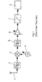
- the coupled via an antenna 1 received signal passes through a specific for the suppression of an image frequency filter 2 to a mixer 3, in which the signal mixed with a set in accordance with the desired channel frequency of a local oscillator 4 and in a fixed, that is from the receiving frequency independent intermediate frequency (IF) is implemented.
- a second, subsequent filter 5 is designed and set up for channel selection on the intermediate frequency stage as well as an aliasing filter for the sampling process of the digitization.
- AGC automatic gain control 6
- the IF signal is adjusted in terms of its level to the input side of an ADC 7 (analog-to-digital converter), wherein in a signal processing unit 8, the now digital signal is converted further, with the aim of Obtaining the wanted signal by demodulation.
- Essential for this known circuit concept is a conversion of a receive signal into a fixed intermediate frequency by mixing with a variable oscillator frequency in the analog range and a subsequent digitization.
- FIG. 3 shows the inventive concept in its basic features.
- the amplifier 8 designates an analogue part which is connected to the antenna 1 on the input side and consists of two filters 9, 10, between which a variable amplifier 11 is located.
- the amplifier 11 may be a single amplifier, but may also be a cascade of amplifiers.
- the amplifier 11 is designed with the proviso that, as viewed at the output of the ADC 12, the noise level generated in a channel of the utility band by the amplifier is less than 10 dB above or below the worst case ADC generated in that channel noise level , In this way, there is a good trade-off between system sensitivity and dynamic range utilization of the ADC.
- the filters 9, 10 serve to select the frequency band coupled in via the antenna 1, the filter 10 being additionally designed to cause disturbances outside the frequency band to be received but generated by the upstream amplifier, such as harmonics or broadband noise to suppress, since these disturbances would otherwise be detected in the subsequent sampling process with the sampling frequency f S and could get into the useful signal (aliasing).
- the amplifier 11 or the cascade of attenuator and fixed amplifier is designed and controlled such that the amplitude of the analog time signal at the output of the filter 10 and at the input of the subsequent ADC 12 is controlled, so that in particular the ADC is not overridden.
- the Amplifier 11 causes a decoupling of the two filters 9, 10, so that add their attenuation values to a total attenuation.
- Denoted at 13 is a digital part connected to the ADC 12, which consists of a digital signal processing unit (DSPE) 14 and a digital-to-analog converter (DAC) 15, at the output of which the useful signal reproducible in the usual way is available.
- the DSPE 14 is set up such that the data stream 16 supplied on the input side with the word width M bits at the frequency f S is further processed, in particular demodulated, and converted on the output side into a data stream 17 having the word width N bits, which represents the useful signal implemented in the subordinate DAC 15.
- the most important element of this concept in the context of the invention is the ADC 12, since this and the sampling frequency f S and their coordination with the frequency position of the tape to be scanned, the decisive influence on the performance of the overall system.
- Fig. 2 shows a way to improve the linearity at the input of the ADC 12 by between this and the filter 10, a transformer 18 with impedance transformation (ratio of secondary to primary side of ü> 1) is arranged.
- Transformer output side, the ADC 12 is connected and in parallel a termination resistor 20.
- the voltage levels at the termination resistor 20 differ by the transmission ratio of the transformer 18 from the voltage levels at the transformer input 19, so that the transformer actually forms an amplifier in this arrangement.
- the levels at the amplifier output can be lower by the gain of the transformer than in the case without the arrangement of a transformer or when using a transformer with a 1: 1 ratio, so that through the amplifier produced distortions are lower. Distortions in a classical amplifier generally increase the further it is driven.
- transformers with the typical for the ADC input level ranges usually have a much greater linearity than amplifiers with conventional power consumption, is with the transformer arrangement according to Fig. 2 , which represents an impedance transformation, achieves an improvement in the linearity at the input of the ADC 12.
- variable amplifier 11 is used in the presentation according to Fig. 3 .
- the attenuator 22 is connected via a digital-to-analog converter (DAC) 23 to the DSPE 14, in which a digital control variable is generated, which is used after analog conversion via the DAC 23 to control the attenuation.
- DAC digital-to-analog converter
- Fig. 4 denotes a selection module, at whose output a selected from the fed antenna signal frequency band is output level-controlled.
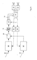
- Fig. 5 shows the application of the invention for the parallel reception of all FM and AM radio frequencies.
- the structures of both paths are basically the same, so that within the selection module between two filters a fixed amplifier with an upstream variable attenuator is arranged, in front of the inputs of the ADC 12, 12 'in each case a transformer 18, 18' for impedance transformation and linearity improvement located. Both paths are connected to a DSPE 14, which has the task of further processing the output from the two ADC 12, 12 'digital data streams.
- channel selection and demodulation paths may be implemented, which may be one or more of the digitized data AM or FM channels select, demodulate and output the resulting audio signals via the DAC 15, 15 '.
- the number of DAC modules or the demodulated channels can be almost arbitrary and is limited only by the performance of the DSPE 14.
- an FM radio band eg the European FM radio band
- an upper path which includes the selection unit 24, and fed to a combiner 25.
- the second input signal of the combiner 25 forms the selected output-side AM band of the selection module 24 '.
- This sample rate is selected so that the FM FM band is sampled in accordance with an undersampling, whereas the AM band is sampled in accordance with an oversampling. This choice of sample rate ensures that the best possible aliasing protection is achieved using common filter characteristics.
- the time signals of both paths are each separately level-controlled. Compared to the representation according to Fig. 5 Only one ADC 12 is required, however, which requires a slightly higher sampling rate, so that the hardware cost for the system can be reduced somewhat. However, this is purchased with a lower blocking resistance of the system and a slightly reduced aliasing protection. This principle is applicable even if the entire global FM radio band is to be sampled directly.
- Fig. 7 shown arrangement clarifies the basic idea of the "digital antenna", here the example of the entire FM radio band and for the band all AM services.
- the entire antenna assembly is denoted by 27, wherein the signals of one or more antennas 1, 1 'are converted by direct sampling into digital data, on the basis of the principle according to the invention, so that the - located in the signal flow direction - before the DSPE 14 assemblies are those of the Fig. 5 . 6 correspond.
- the output signals of the DSPE 14 are supplied to one or more digital data buses 26, 26 'via which the output signals of the digital antenna 27 are redistributed to one or more terminals 28, 28'.
- the digital data forwarded via the data buses 26, 26 ' can forward either parts or individual channels or subbands or even the entire bands directly scanned by the digital antenna 27 to the terminals.
- all the FM and AM radio services would be present in parallel at each of the terminals 28, 28 ', so that each terminal could demodulate or evaluate and output any number of channels in parallel by means of a plurality of tuners realized in software.
- the illustrated concept of the digital antenna 27 thus offers the highest degree of flexibility and reconfigurability since all other functions can be represented by software at the output of the digital antenna and the entire useful band is available in digital form.
- each of the terminals 28, 28 ' has access to the respective entire useful band, namely the entire AM and FM radio band, these selection paths must be adjustable by control signals from the terminals 28, 28'.
- the digital data bus 26, 26 ' is in each case configured bidirectionally and therefore may only have a smaller capacity since only parts of the output data of the digital antenna 27 are transmitted via the respective data bus. In this case, therefore, a high degree of flexibility that the digital Antenna 27 offers, exchanged against lower demands on the transmission capacity of the digital data bus.
- Fig. 8 shows the application of the invention in an antenna diversity concept with four antennas 1, 1 ', 1 ", 1"', so that a total of four input paths are found, each individually according to a single path Fig. 6 correspond.
- the diversity functionality can then be represented by software, wherein for each channel to be received from each digitally present antenna signal, this channel is selected and combined or switched according to the diversity concept.
- the tuner (s) are also represented by software.
- FIG. 8 Although illustrated example relates to a diversity system for the global FM radio band with four input antennas and two tuners represented by the DSPE 14 with correspondingly two audio outputs for demodulated signals.
- the principle is fundamentally expandable to any number of bands and any number of input antennas with a number greater than 1 and a correspondingly arbitrary number of "software tuners".
- FIG. 9 illustrates a combination of the invention with analogue tuners for the integration of further services and frequency ranges.
- the direct sampling concept can be combined with conventional mixing concepts.
- Essential for the inventive concept is an efficient and optimal utilization of the ADC dynamic range.
- the useful bands to be sampled directly here: AM and FM band
- the combiner consists of a direct merging of input and output lines.
- the sampling rate f S of the ADC is chosen such that the FM band is oversampled according to the invention (frequency position in the 2nd Nyquist zone) and the AM band is oversampled.
- the antenna 1 ", 1"' converts signal frequency bands to one or more intermediate frequencies (IF1, IF2) by means of one or more analogue tuners 29, 29'
- intermediate frequency signals are combined by means of a combiner 25 'and
- a suitable selection of the intermediate frequencies and with sufficient selection of the intermediate frequency signals it is achieved that a simultaneous digitization of the intermediate frequency signals is possible without significant aliasing interference
- the use of several identical tuners offers the possibility of antenna switching and phase diversity or the simultaneous reception of multiple channels or services on different frequencies
- the evaluation of the signals on the intermediate frequencies is performed as in direct sampling by means of several implemented on the DSPE 14 digital tuner paths, by means of which also a simultaneous evaluation of the directly sampled channels in the ADC 12 is possible.
- the ADC 12 ' can be supplied via the combiner 25' in parallel with the two tuner paths 29, 29 ', a further direct sampled FM band for the implementation of antenna or phase diversity.
- the integration of further bands to be scanned directly can also take place via one or more additional ADC or ADC channels.
- This band to the DSPE is also possible via another ADC or ADC channel.
- FIG. 10 illustrates a combination of the invention with analog tuners for the integration of further services and frequency ranges with optimized frequency domain utilization of the ADCs.
- the two intermediate frequency signals (IF1, IF2) and the output signals of the selection modules 24, 24 'to be sampled directly are now not supplied to the same ADC or ADC channel, but are split between the two ADCs 12, 12' and in each case by means of a combiner 25 ", Since the intermediate frequency signals for receiving individual channels are usually narrowband compared to the direct sampled band, a better utilization of the available ADC input frequency range is made possible Fig. 9 can the required sampling rate f S of the ADC for the arrangement after Fig. 10 be reduced.
- switches instead of combiners.
- increased aliasing protection is achieved at the expense of a loss of simultaneous receivability of the signal applied to the switch (or combiner).
- Implicitly, such a behavior can also be achieved by lowering or additionally attenuating the levels in the analogue tuners and / or the selection modules while maintaining the combiners.
- antennas 1, 1 ', 1 is always only one antenna via a switch 31 the Sparabtastungsempffiter consisting of the selection module 24, (here: set up for FM reception), the ADC 12 with the sampling frequency f s , the DACs 23rd , 15, 15 'and the DSPE 14.
- the logic for switching between the antennas is integrated in the diversity module 30. Alternatively, this logic may also be included in a digital implementation in the DSPE in which an evaluation of the digitized received signal takes place whose base is switched between the antennas.
- This concept allows receive signal optimization using antenna switching diversity for a limited frequency band or channel, which is sufficient for many applications. Compared to a direct sampling receiver with phase diversity for all receiving channels, for which the complete useful band must be scanned at least twice, the hardware complexity for this antenna switching diversity concept is significantly reduced because the useful band is scanned only once.
- This Antennenschaltdiversityun can be extended to all forms of the invention shown so far, which are therefore also subject of this invention.
Abstract
Description
Die Erfindung bezieht sich auf ein Breitband-Empfangssystem entsprechend dem Oberbegriff des Anspruchs 1.The invention relates to a broadband receiving system according to the preamble of
Heutigen, nach den Prinzipien des Homo- oder des Heterodynempfängers eingerichteten Empfängerarchitekturen, und zwar sowohl für einen stationären Einsatz als auch für einen Einsatz in Fahrzeugen, ist gemeinsam, dass die Empfangsfrequenz eines Signals mit einer im Empfänger generierten, einstellbaren Oszillatorfrequenz gemischt und in eine feste Zwischenfrequenz umgesetzt wird, die anschließend digitalisiert und weiter verarbeitet wird. Prinzipiell kann auf diese Weise ein breites Frequenzband empfangen werden, wobei durch die einer Digitalisierung vorgelagerte Mischstufe und die feste Zwischenfrequenz die Anforderungen an die Leistungsfähigkeit, insbesondere die Abtastrate sowie die Auflösung eines ADC (Analog-Digital-Konverter), unabhängig von der jeweils gewählten Empfangsfrequenz sind. Durch die Wahl einer niedrigen Zwischenfrequenz und einer guten Selektion eines Bandes oder Kanals werden die Anforderungen an den ADC weiter reduziert und eine gute Ausnutzung von dessen Dynamikbereich erreicht.Today, based on the principles of homo- or heterodyne receiver receiver architectures, both for stationary use and for use in vehicles, has in common that the reception frequency of a signal mixed with a generated in the receiver, adjustable oscillator frequency and in a fixed Intermediate frequency is implemented, which is then digitized and processed further. In principle, a wide frequency band can be received in this way, whereby the requirements of the performance, in particular the sampling rate and the resolution of an ADC (analog-to-digital converter), regardless of the respectively selected receiving frequency by the upstream of a digitization mixer and the fixed intermediate frequency are. Choosing a low IF and good tape or channel selection further reduces the demands on the ADC and makes good use of its dynamic range.
Dieses bekannte Konzept ist jedoch in vielen Fällen, je nach der konkreten Ausführung, durch Störungen gekennzeichnet, die von einem Phasenrauschen eines Lokaloszillators, Nebenempfangsstellen durch Harmonische des Oszillators, I-Q-Imbalance-Problemen und von einer unvollkommenen Spiegelfrequenzunterdrückung durch die der Mischstufe vorgelagerten Filter ausgehen. Zusätzlich führt eine Durchgangsdämpfung der Mischstufe zu einem Empfindlichkeits- und Leistungsverlust. Sämtliche dieser Unvollkommenheiten machen umfangreiche Schaltungsmaßnahmen erforderlich, um eine Korrektur oder wenigstens eine Minderung dieser Störungen zu erreichen.However, this known concept is in many cases, depending on the specific embodiment, characterized by disturbances emanating from a phase noise of a local oscillator, secondary reception points by harmonics of the oscillator, IQ imbalance problems and an imperfect image rejection by the mixer upstream filter. In addition, a passage loss of the mixer leads to a loss of sensitivity and power. All of these imperfections require extensive circuitry to achieve a correction or at least a mitigation of these disturbances.
Auch ist bei diesem Konzept meist die Selektion nur eines Kanals vorgesehen, um die Anforderungen an den nachgeschalteten ADC gering zu halten. Da dieser Zustand hardwaremäßig nach Maßgabe eines definierten Standards festgelegt ist, ist eine Umstellung auf einen anderen Standard, z. B. mit einer anderen Kanalbreite, so dass ein anderes Kanalfilter erforderlich wird, mit einem nicht vertretbaren Aufwand verbunden, da dies mit einem Eingriff in die Hardware verbunden wäre. Die Flexibilität dieses bekannten Systems ist somit gering.Also, in this concept mostly the selection of only one channel is provided to keep the requirements of the downstream ADC low. Since this state is defined in terms of hardware in accordance with a defined standard, a conversion to another standard, eg. B. with a different channel width, so that another channel filter is required, associated with an unreasonable effort, since this would be associated with an intervention in the hardware. The flexibility of this known system is thus low.
Der Umstand, dass nur ein Kanal empfangen wird, zwingt bei solchen Anwendungen, bei denen mehrere Kanäle gleichzeitig empfangen werden müssen, zu besonderen Maßnahmen. Es besteht beispielsweise bei in Fahrzeugen eingesetzten Radioempfängern ein Bedürfnis, mehr als nur einen Kanal gleichzeitig zu empfangen. Regelmäßig sind in diesen Fällen nämlich drei, in Hardware realisierte Empfängerzweige mit jeweils unterschiedlichen Empfangskanälen aktiv, nämlich ein erster Zweig, der gerade abgehört wird, ein zweiter, der im Hintergrund nach Alternativfrequenzen des gleichen Programminhalts sucht und ein dritter, der auf Verkehrsfunkanwendungen eingestellt ist. Die Anwendung der bekannten Techniken führt zu der Einrichtung von drei voneinander unabhängigen Empfangszweigen, von denen jeder eine Mischstufe, eine Kanalselektion, das heißt ein auf die Bandbreite des empfangenen Dienstes angepasstes Zwischenfrequenzfilter sowie einen ADC aufweist, so dass sich insgesamt ein entsprechend erhöhter Hardwareaufwand ergibt.The fact that only one channel is received forces special measures to be taken in those applications where multiple channels need to be received simultaneously. For example, in radio receivers used in vehicles, there is a need to receive more than one channel at a time. In fact, in these cases, three receiver branches implemented in hardware, each with different receiving channels, are regularly active, namely a first branch which is being monitored, a second, which searches in the background for alternative frequencies of the same program content and a third, which is set for traffic applications. The application of the known techniques leads to the establishment of three mutually independent reception branches, each of which has a mixing stage, a channel selection, ie an adapted to the bandwidth of the received service intermediate frequency filter and an ADC, so that the overall result is a correspondingly increased hardware complexity.
Um dem Bedürfnis nach einem Parallelempfang mehrerer Kanäle entgegenzukommen, und zwar ohne die ansonsten hiermit einhergehende Vervielfachung von Empfangszweigen der vorstehend genannten Art, somit unter Vermeidung eines entsprechend erhöhten Hardwareaufwandes, ist bei digitalen Radioempfängern ein Trend erkennbar, die Schnittstelle zwischen analoger und digitaler Signalverarbeitung so weit wie möglich an die Antenne zu verlegen, um ein Höchstmaß an Flexibilität des Empfangssystems zu gewährleisten, wobei von dem Umstand Gebrauch gemacht wird, dass die Funktion einer digitalen Hardware letztendlich softwaremäßig definiert wird, so dass diese im Bedarfsfall ohne großen Aufwand umprogrammmiert werden kann, beispielsweise für eine Anpassung an andere Standards.In order to meet the need for a parallel reception of multiple channels, without the otherwise associated here multiplication of reception branches of the aforementioned type, thus avoiding a correspondingly increased hardware cost, a trend is visible in digital radio receivers, the interface between analog and digital signal processing so far as possible to the antenna to ensure maximum flexibility of the receiving system, taking advantage of the fact that the function of a digital hardware is ultimately defined by software so if necessary, it can be reprogrammed without great effort, for example for adaptation to other standards.
Das Konzept eines Empfangssystems, bei welchem eine Digitalisierung empfangener Analogsignale in der Nähe der Antenne und unter Vermeidung einer analogen Mischstufe stattfindet, ist beispielsweise aus "A Software Defined Multistandard Tuner Platform for Automotive Applications",
Das dort vorgestellte Konzept einer Direktabtastung ist durch eine Abtastrate nach dem Prinzip der Unterabtastung bei fS = 76,8 MHz so angelegt, dass das zu digitalisierende UKW-Radiofrequenzband von 87,5 MHz bis 108 MHz komplett und mittig zu den Bandgrenzen im 3. Nyquistband liegt. Eine Selektion und eine Aliasingunterdrückung erfolgt mittels kaskadierter Bandpassfilter und Verstärker, wobei der Verstärkungsfaktor bei den Verstärkern teilweise digital programmierbar ist.The concept of a direct sampling presented there is designed by a sampling rate on the principle of subsampling at f S = 76.8 MHz so that the digitized FM radio frequency band from 87.5 MHz to 108 MHz complete and centered to the band boundaries in the 3rd Nyquistband lies. Selection and aliasing suppression is performed by means of cascaded bandpass filters and amplifiers, the amplification factor in the amplifiers being partially digitally programmable.
Weil bei diesem Konzept der Direktabtastung keine analoge Mischstufe vorhanden ist, entfallen die vorstehend genannten, mit der Mischung im Analogen verbundenen Probleme. Auch ist eine erhöhte Flexibilität für den Fall einer Änderung des Standards gegeben. Ungünstig stellt sich jedoch die Wahl der Abtastrate des UKW-Radiobands dar, da dies einen hohen Grad an Filtermaßnahmen erforderlich macht, um die Aliasingunterdrückungsanforderungen für die Digitalisierung dieses Bandes zu erfüllen. Dies führt zu einem hohen Hardwareaufwand und - hiermit zusammenhängend - u. U. zu einer Störanfälligkeit des Systems. Extensive Filtermaßnahmen führen ferner zu einer hohen Dämpfung im Durchgangsband, so dass in Abhängigkeit von der Positionierung der Filter im analogen Empfangspfad die Empfindlichkeit des Systems vermindert wird, oder es werden die Linearitätsanforderungen an analoge Frontendverstärker erhöht.Because there is no analogous mixing step in this direct sampling concept, the above-mentioned problems associated with mixing in the analogue are eliminated. There is also increased flexibility in the event of a change in the standard. However, the choice of sampling rate of the FM radio band is unfavorable because it requires a high degree of filtering to meet the aliasing suppression requirements for digitizing that band. This leads to a high expenditure of hardware and - hereby connected - u. U. to one Susceptibility of the system. Extensive filtering also results in high passband attenuation, which reduces the sensitivity of the system depending on the positioning of the filters in the analog receive path, or increases the linearity requirements of analog front-end amplifiers.
Ein weiteres Problem könnte sich bei diesem Konzept einer Direktabtastung aus dem Umstand ergeben, dass - betrachtet aus der Richtung der Antenne - dieser im Verlauf des Signalpfades benachbart ein Festverstärker zugeordnet ist. Dies kann dazu führen, dass sich bei für den Fall eines Nahempfangs möglichen hohen Signalpegeln bzw. Starksignalen Verzerrungen aufgrund eines nichtlinearen Verhaltens des Verstärkers ergeben, so dass Intermodulationsprodukte oder harmonische Störer im Nutzband auftreten und die Empfangsqualität veschlechtern.Another problem could arise in this concept of direct sampling from the fact that - as viewed from the direction of the antenna - this is adjacent to a fixed amplifier in the course of the signal path. This can lead to distortions due to a nonlinear behavior of the amplifier in the case of a close-up of possible high signal levels or strong signals, so that intermodulation products or harmonic interferers occur in the useful band and impair the reception quality.
Die Aufgabe der Erfindung besteht darin, ein Empfangssystem der eingangs bezeichneten Gattung mit einfacher Systemarchitektur und gleichzeitig hoher Leistungsfähigkeit bereitzustellen, welches in einfacher Weise aufbauend auf den Techniken der Direktabtastung eines vollständigen Frequenzbandes zwecks Umwandlung in eine digitale Form Standardunabhängigkeit sowie die Möglichkeit eines Parallelempfangs mittels ausschließlich softwaremäßig dargestellter Tuner ermöglicht.The object of the invention is to provide a receiving system of the type described above with simple system architecture and high performance at the same time based on the techniques of direct sampling of a complete frequency band for conversion into a digital form standard independence and the possibility of parallel reception by means of software only shown tuner allows.
Gelöst ist diese Aufgabe bei einem solchen Empfangssystem durch die Merkmale des Kennzeichnungsteils des Anspruchs 1.This object is achieved in such a receiving system by the features of the characterizing part of
Erfindungswesentlich ist hiernach der zentrale ADC (Analog-Digital-Konverter), insbesondere dessen Abtastfrequenz fs, welche im Zusammenhang mit dem umzusetzenden Nutzband gesehen werden muss. In jedem Fall muss das analoge Eingangssignal des ADC bandbegrenzt sein und durch eine geeignete Wahl der Abtastfrequenz dafür Sorge getragen werden, dass keine Störungen in der Form eines Aliasing auftreten. Erfindungsgemäß ist grundsätzlich, nämlich zumindest für den FM-Bereich eine Unterabtastung eingerichtet, und zwar derart, dass das abzutastende Nutzband vollständig in der zweiten Nyquistzone liegt, und zwar vorzugsweise mittig. Dies ermöglicht einen guten Kompromiss zwischen den Anforderungen an die Filtercharakteristik des analogen Teils und der Leistungsfähigkeit des ADC und weiterer Funktionsgruppen des digitalen Teiles. Speziell für die Direktabtastung des FM-Bandes ergeben sich im Vergleich zu bekannten Anwendungen einer Direktabtastung in der Form einer Unterabtastung geringere Anforderungen an die Flankensteilheit der Charakteristika der analogen Vorfilter, ein geringerer Hardwareaufwand sowie eine geringe Durchgangsdämpfung, und zwar bei vergleichbarer Empfängerempfindlichkeit und hoher Aliasingunterdrückung. Im Rahmen des analogen Teils des Systems können somit Standardfilterkomponenten benutzt werden. Beispielsweise kann für das europäische UKW-FM-Radio-Band von fmin = 87,5 MHz bis fmax = 108 MHz erfindungsgemäß eine Abtastfrequenz von 141, 5 MHz genutzt werden. Abweichungen demgegenüber, solange sich das Nutzband in der zweiten Nyquistzone befindet, sind zulässig.Essential to the invention is hereafter the central ADC (analog-to-digital converter), in particular its sampling frequency f s , which must be seen in connection with the useful band to be converted. In any case, the analog input signal of the ADC must be band-limited and, by appropriate selection of the sampling frequency, care should be taken to avoid interference in the form of aliasing. According to the invention, in principle, at least for the FM range, a sub-sampling is set up, namely such that the useful band to be scanned lies completely in the second Nyquist zone, preferably in the center. This allows a good compromise between the requirements of the filter characteristic of the analog part and the performance of the ADC and other functional groups of the digital part. Especially for the direct sampling of the FM band, compared to known applications of direct sampling in the form of sub-sampling, there are less requirements on the slope of the characteristics of the analog prefilters, less hardware and low transmission loss, with comparable receiver sensitivity and high aliasing suppression. Thus, within the analog part of the system, standard filter components can be used. For example, for the European FM-FM radio band from f min = 87.5 MHz to f max = 108 MHz, a sampling frequency of 141.5 MHz can be used according to the invention. By contrast, deviations are permissible as long as the utility belt is in the second Nyquist zone.
Die Abtastfrequenz entsprechend den Merkmalen des Anspruchs 2 ist eine optimale Frequenz, die sich ergibt, wenn die relativen Bandbreiten beider Übergangsbänder gleich sind. Die Begriffe relatives oberes bÜg,ob und relatives unteres Übergangsband bÜg,un sind jeweils definiert als bÜg,ob = fk,ob/fmax und bÜg,un = fmin/fk,un, wobei fk,un die untere und fk,ob die obere kritische Eckfrequenz sind, bei denen unter- und oberhalb des Nutzbandes (durch Aliasing) erstmalig Signalanteile in das Nutzband fallen. Zusätzlich vorteilhaft, jedoch nicht zwingend erforderlich, ist eine symmetrische Charakteristik der Filter für die in diesem Fall gilt, dass die durch das Selektionsmodul hervorgerufene Dämpfung bei den kritischen Frequenzen fk,un und fk,ob gleich groß sind. Die vorgeschlagene symmetrische Dimensionierung der Filter und die Wahl der Abtastfrequenz so, dass die Bedingung bÜg,un = bÜg,ob erfüllt ist, gewährleistet optimalen Schutz gegen Störungen durch Aliasing im Nutzband bei gleichzeitig einer einfachen, aufwandsarmen Filterrealisierung.The sampling frequency according to the features of
Die Merkmale der Ansprüche 3 bis 5 sind auf die Ausgestaltung des analogen Teiles gerichtet. Aufgrund der geringen Anforderungen an die Flankensteilheit können Filter einer niedrigen Ordnung eingesetzt werden, wobei alternativ zum Schutz des ADC vor einer Übersteuerung ein regelbarer Verstärker oder ein Festverstärker in Kombination mit einem regelbaren Dämpfungsglied eingesetzt werden kann. Durch das dem Festverstärker vorgeschaltete Dämpfungsglied wird erreicht, dass der Eingang des Verstärkers auch bei höchsten Signalpegeln von der Antenne vor Übersteuerungen geschützt ist. Das Dämpfungsglied kann sowohl eine kontinuierliche als auch eine stufenförmige Stellcharakteristik aufweisen. Von besonderem Vorteil ist die Struktur des Selektionsmodules nach
Eine Einrichtung des Frontendverstärkers entsprechend den Merkmalen des Anspruchs 6 führt zu einer optimalen Leistungsfähigkeit des direktabtastenden Systems, insbesondere zu einer optimalen Nutzung des Dynamikbereiches des ADC.A device of the front-end amplifier according to the features of claim 6 leads to an optimal performance of the direct-sampling system, in particular to an optimal use of the dynamic range of the ADC.
Entsprechend den Merkmalen des Anspruchs 7 ist zur Linearitätsverbesserung ein Trafo mit Impedanztransformation am Eingang des ADC vorgesehen. Über einen Trafo mit einem Übersetzungsverhältnis von Sekundär- zu Primärseite von ü > 1 vor dem Eingang des ADC wird eine Impedanztransformation zwischen einem sekundärseitig parallelgeschalteten Abschlusswiderstand (20,
Die Merkmale der Ansprüche 8 bis 10 sind auf Funktionen der DSPE gerichtet. Diese bestehen in der softwaremäßigen Darstellung eines oder auch mehrerer Tuner, jedoch auch von zahlreichen, ebenfalls softwaremäßig darstellbaren Steuerfunktionen. Lediglich beispielhaft sei auf AGC-Algorithmen (Automatic Gain Control) hingewiesen, die im Wege einer Softwareimplementierung einfach realisierbar sind. Dies betrifft insbesondere auch nachträgliche Änderungen, welche unter Zugrundelegung einer analogen Technik mit einem unverhältnismäßigen Aufwand verbunden wären.The features of
Die Merkmale der Ansprüche 11 bis 15 sind auf Anwendungen der erfindungsgemäßen Form einer Direktabtastung gerichtet, welche die Integration unterschiedlicher Dienste in ein Systemdesign betreffen, beispielsweise die Behandlung von FM-und AM-Diensten, welch letztere in dem Band von 150 kHz bis 30 MHz untergebracht sind, das Konzept der digitalen Antenne sowie ein Antennendiversitykonzept.The features of
Das Konzept der digitalen Antenne ermöglicht einer Mehrzahl von Endgeräten beispielsweise den Parallelempfang, wobei den Endgeräten über die DSPE Teilbänder bzw. einzelne Kanäle, oder auch das gesamte im Wege der Direktabtastung gewonnene Nutzband zugeleitet wird. Im letzten Fall würden an jedem Endgerät sämtliche AM- und FM-Radiodienste parallel anliegen, so dass jedes Endgerät mittels mehrerer softwaremäßig dargestellter Tuner beliebig viele Kanäle parallel demodulieren und auswerten bzw. ausgeben könnte. Das Konzept der digitalen Antenne bietet somit ein Höchstmaß an Flexibilität und Rekonfigurierbarkeit, da am Ausgang der digitalen Antenne sämtliche Funktionen softwaremäßig darstellbar sind und das gesamte Nutzband digital verfügbar ist.The concept of the digital antenna allows a plurality of terminals, for example, the parallel reception, wherein the terminals via the DSPE subbands or individual channels, or even the entire obtained by means of direct sampling Nutzband is fed. In the latter case, all AM and FM radio services would be present in parallel at each terminal, so that each terminal could demodulate and evaluate or output any number of channels in parallel by means of a plurality of software-represented tuners. The concept of the digital antenna thus offers the highest degree of flexibility and reconfigurability, since all functions can be represented by software at the output of the digital antenna and the entire useful band is available digitally.
Bei einem Antennendiversitykonzept können über die DSPE x Signalpfaden y Datenströme bzw. softwaremäßig dargestellte Tuner auf der DSPE zugeordnet werden. Sämtliche, mit der laufenden Bewertung und Zuordnung von Tunern und Signalpfaden verbundenen Funktionen können softwaremäßig über die DSPE abgewickelt werden. Aufgrund einer somit vollständigen Softwareimplementierung bietet dieses Diversitykonzept mit Direktabtastung ein Höchstmaß an Flexibilität und einen großen Spielraum in der Anwendung digitaler Algorithmen und Optimierungen.In the case of an antenna diversity concept, it is possible via the DSPE to assign x signal paths y data streams or software-represented tuners on the DSPE. All functions associated with the ongoing evaluation and assignment of tuners and signal paths can be processed by the software via the DSPE. Due to a complete software implementation This diversity concept with direct sampling offers the highest degree of flexibility and a wide latitude in the application of digital algorithms and optimizations.
Gemäß den Merkmalen des Anspruchs 16 wird eine Mehrzahl der ADC mit einer gemeinsamen Abtastfrequenz beaufschlagt. Dieses ist bei einer Verwendung des Empfangssystems für den gleichzeitigen Empfang im FM- und im AM-Bereich dahingehend angelegt, dass die eingangs genannten Bedingungen einer Unterabtastung für den FM-Bereich gegeben sind, wohingegen für den AM-Bereich bei dieser Abtastfrequenz eine Überabtastung vorliegt. Eine Unterabtastung über das gesamte Spektrum ist in diesem Fall nicht möglich. Aufgrund der gemeinsamen Abtastfrequenz können jedoch beide Bereiche mittels desselben Clockgenerators, z. B. eines Festfrequenzoszillators, betrieben werden. Die Vorteile der einfachen Systemarchitektur und insbesondere der einfachen Architektur des Analogteils bei gleichzeitig hoher Leistungsfähigkeit sind für den Fall der Überabtastung des AM-Bereiches ebenfalls vorhanden.According to the features of
Die Merkmale der Ansprüche 17 und 18 sind auf die Steuerung eines analogseitigen Dämpfungsgliedes oder eines hier eingesetzten Verstärkers gerichtet. Dies ist, ausgehend von einem in der DSPE eingerichteten AGC-Algorithmus, gegeben, bei dem eine inverse Steuerungskennlinie des Dämpfungsgliedes in digitaler Form oder in einer look-up-Tabelle (LUT) abgelegt ist. Auf diese Weise ist sichergestellt, dass eine Pegeländerung am Eingang des ADC oberhalb einer oder über eine AGC-Schwelle, beispielsweise hervorgerufen durch Fadingeffekte im selektierten Band, nahezu direkt gegengeregelt werden kann. Hierzu wird die Amplitude der Pegeländerung bestimmt und unter Berücksichtigung einer momentan eingestellten Steuerungsspannung der zugehörige Wert aus der LUT für die Ansteuerung des Dämpfungsgliedes verwendet, der diesen Pegelsprung gerade exakt ausgleicht.The features of
Da ein derartiger AGC-Algorithmus lediglich auf Vergleichsoperationen und Speicherzugriffen beruht und keine Filter benötigt werden, die zu Verzögerungen führen würden, wird auf diese Weise eine Fast-Attack-Characteristik erzielt und ein guter Schutz des ADC vor einer Übersteuerung gewährleistet. Insbesondere können Pegelanstiege schnellstmöglich und exakt ausgeglichen werden, wobei eine Reaktionszeit lediglich von der Stellgeschwindigkeit des Dämpfungsglieds abhängt.Since such an AGC algorithm is based only on comparison operations and memory accesses and no filters are required, the Delays would be achieved in this way, a fast-attack characteristic and ensures good protection of the ADC from overdriving. In particular, level increases can be compensated for as quickly as possible and exactly, wherein a reaction time only depends on the positioning speed of the attenuator.
Bei einem solchen AGC-Konzept können ein Fast-Attack-, ein Slow-Release-oder auch ein Peak-Hold-Ansatz genutzt werden, so dass stets eine gute Aussteuerung des ADC gegeben ist. Insbesondere eine exakte und beliebig konfigurierbare Peak-Hold-Funktion ist dagegen auf analogem Weg praktisch kaum realisierbar.In such AGC concept, a fast-attack, a slow-release or a peak-hold approach can be used, so that there is always a good modulation of the ADC. In contrast, an exact and arbitrarily configurable peak-hold function, on the other hand, is virtually impossible to realize in an analogous way.
Diese Ansätze enthalten neben der Fast-Attack-Reaktion auf einen Pegelsprung oberhalb der oder über die AGC-Schwelle eine Peak-Hold-Funktion, bei der nach dem Auftreten eines Pegelspitzenwertes der zur Ausregelung dieses Spitzenwertes zugehörige Stellwert für das Dämpfungsglied eine Zeitlang gehalten wird, wenn kein neuer Pegelspitzenwert auftritt. Tritt kein neuer Spitzenwert auf, setzt das Slow-Release ein, so dass sich die Dämpfung langsam verringert, bis entweder ein neuer Spitzenwert auftritt, der oberhalb der AGC-Schwelle liegt oder bis die minimale Dämpfungseinstellung des Dämpfungsgliedes erreicht ist.In addition to the fast-attack response to a level jump above or above the AGC threshold, these approaches include a peak-hold function in which, after the occurrence of a level peak, the control value for the attenuator associated with the adjustment of this peak value is held for a period of time. if no new level peak occurs. If no new peak occurs, the slow release begins, so that the attenuation slowly decreases until either a new peak occurs that is above the AGC threshold or until the minimum attenuation setting of the attenuator is reached.
Indem die Parameter des AGC-Konzeptes entsprechend eingestellt werden, kann bei allen Pegelszenarien gewährleistet werden, dass trotz einer AGC-Schwelle knapp unterhalb der Vollaussteuerung des ADC fast nie eine Übersteuerung des ADC eintritt.By setting the parameters of the AGC concept accordingly, it can be ensured in all level scenarios that an overloading of the ADC almost never occurs despite an AGC threshold just below the full scale of the ADC.
Die vorliegende, auf dem Konzept der Direktabtastung aufbauende Empfängerarchitektur bietet aufgrund eines hohen Maßes an softwaremäßig darstellbaren Funktionen ein Höchstmaß an Flexibilität und Konfigurierbarkeit, insbesondere in allen Fällen, in denen ein Parallelempfang mehrerer Kanäle erwünscht ist. Es zeichnet sich gegenüber bekannten Formen der Direktabtastung aufgrund der gewählten Abtastfrequenz durch einen einfachen, kostengünstig realisierbaren Aufbau seines analogen Teiles aus.The present receiver architecture based on the concept of direct sampling offers a high degree of flexibility and configurability due to a high degree of software-representable functions, especially in all cases where parallel reception of multiple channels is desired. It is distinguished from known forms of direct sampling due to the selected sampling frequency by a simple, inexpensive realizable structure of its analog part.
Die Merkmale der Ansprüche 19 bis 23 sind auf Möglichkeiten einer Zusammenfassung des erfindungsgemäßen Direktabtastungskonzepts mit herkömmlichen Mischkonzepten einschließlich dessen Einbeziehung in ein Antennendiversitykonzept gerichtet.The features of
Die Erfindung wird im Folgenden unter Bezugnahme auf die beiliegenden Zeichnungen näher erläutert. Es zeigen:
-
Fig. 1 ein Blockschaltbild eines herkömmlichen Heterodynempfängers; -
Fig. 2 ein Blockschaltbild zur Verbesserung der Linearität vor dem Eingang eines Analog-Digital-Konverters; -
Fig. 3 eine Prinzipdarstellung eines Blockschaltbildes eines erfindungsgemäßen Empfangssystems; -
Fig. 4 ein Blockschaltbild eines erfindungsgemäßen Empfangsystems mit verbesserter Linerarität; -
Fig. 5 ein Blockschaltbild eines erfindungsgemäßen Empfangssystems mit zwei Analog-Digital-Konvertern; -
Fig. 6 ein Blockschaltbild eines erfindungsgemäßen Empfangssystems mit einem Analog-Digital-Konverter; -
Fig. 7 ein Blockschaltbild einer digitalen Antenne als Anwendung eines erfindungsgemäßen Empfangssystems; -
Fig. 8 ein Blockschaltbild einer Antennendiversity-Anordnung als Anwendungsfall eines erfindungsgemäßen Empfangssystems; -
Fig. 9 ein Blockschaltbild der Erfindung in Form eines direktabtastenden Empfängers für AM und FM in Kombination mit analogen Tunern für die Integration von weiteren Diensten und selektierten Frequenzbereichen; -
Fig. 10 ein Blockschaltbild der Erfindung in Form eines direktabtastenden Empfängers für AM und FM in Kombination mit analogen Tunern für die Integration von weiteren Diensten und selektierten Frequenzbereichen mit reduzierten Anforderungen an die ADC (12, 12') für minimale Störungen durch Aliasing; -
Fig. 11 eine Kombination der Erfindung mit einem aufwandsarmen Antennenschaltdiversitykonzept für die Optimierung der Signalqualität insbesondere eines schmalbandigen Empfangsbandes oder eines Einzelkanals.
-
Fig. 1 a block diagram of a conventional heterodyne receiver; -
Fig. 2 a block diagram for improving the linearity before the input of an analog-to-digital converter; -
Fig. 3 a schematic diagram of a block diagram of a receiving system according to the invention; -
Fig. 4 a block diagram of a receiving system according to the invention with improved Linerarität; -
Fig. 5 a block diagram of a receiving system according to the invention with two analog-to-digital converters; -
Fig. 6 a block diagram of a receiving system according to the invention with an analog-to-digital converter; -
Fig. 7 a block diagram of a digital antenna as an application of a receiving system according to the invention; -
Fig. 8 a block diagram of an antenna diversity arrangement as an application of a receiving system according to the invention; -
Fig. 9 a block diagram of the invention in the form of a direct sampling receiver for AM and FM in combination with analogue tuners for the integration of other services and selected frequency ranges; -
Fig. 10 a block diagram of the invention in the form of a direct-sampling receiver for AM and FM in combination with analogue tuners for the integration of other services and selected frequency bands with reduced requirements for the ADC (12, 12 ') for minimal interference due to aliasing; -
Fig. 11 a combination of the invention with a low-overhead Antennenschaltdiversitykonzept for optimizing the signal quality in particular a narrowband receiving band or a single channel.
Es wird im Folgenden zunächst auf die Zeichnungsfigur 1 Bezug genommen, welche das Schaltungskonzept eines herkömmlichen Heterodynempfängers zeigt.Reference is first made below to the drawing figure 1, which shows the circuit concept of a conventional heterodyne receiver.
Das über eine Antenne 1 eingekoppelte Empfangssignal gelangt über ein für die Unterdrückung einer Spiegelfrequenz bestimmtes Filter 2 zu einer Mischstufe 3, in der das Signal mit einer nach Maßgabe des gewünschten Kanals eingestellten Frequenz eines Lokaloszillators 4 gemischt und in eine feste, das heißt von der Empfangsfrequenz unabhängige Zwischenfrequenz (ZF) umgesetzt wird. Ein zweites, sich anschließendes Filter 5 ist zur Kanalselektion auf der Zwischenfrequenzstufe sowie als Aliasingfilter für den Abtastprozess der Digitalisierung bestimmt und eingerichtet. Durch eine automatische Verstärkungsregelung 6 (AGC) wird das ZF-Signal hinsichtlich seines Pegels an die Eingangsseite eines ADC 7 (Analog-Digital-Konverter) angepasst, wobei in einer Signalverarbeitungseinheit 8 das nunmehr digitale Signal weiter umgesetzt wird, und zwar mit dem Ziel einer Gewinnung des Nutzsignals durch Demodulation.The coupled via an
Wesentlich für dieses bekannte Schaltungskonzept ist eine Umsetzung eines Empfangsignals in eine feste Zwischenfrequenz durch Mischung mit einer variablen Oszillatorfrequenz im analogen Bereich und eine sich hieran anschließende Digitalisierung.Essential for this known circuit concept is a conversion of a receive signal into a fixed intermediate frequency by mixing with a variable oscillator frequency in the analog range and a subsequent digitization.
Zur Vermeidung der mit diesem bekannten Konzept verbundenen, eingangs bereits dargelegten Unzulänglichkeiten, welche bei der Darstellung eines gleichzeitigen Empfangs mehrerer Kanäle auftreten, wird zunächst auf die Zeichnungsfigur 3 Bezug genommen, welche das erfindungsgemäße Konzept in Grundzügen zeigt.In order to avoid the deficiencies associated with this known concept, which have already been outlined above, which occur in the representation of a simultaneous reception of several channels, reference is initially made to drawing FIG. 3, which shows the inventive concept in its basic features.
Mit 8 ist ein analoger Teil bezeichnet, der eingangsseitig mit der Antenne 1 in Verbindung steht und aus zwei Filtern 9, 10 besteht, zwischen denen sich ein variabler Verstärker 11 befindet. Es kann sich bei dem Verstärker 11 um einen einzelnen Verstärker, jedoch auch um eine Kaskade von Verstärkern handeln. Der Verstärker 11 ist mit der Maßgabe angelegt, dass, betrachtet am Ausgang des ADC 12, der in einem Kanal des Nutzbands durch den Verstärker erzeugte Rauschpegel weniger als 10 dB oberhalb oder auch unterhalb des im ungünstigsten Fall von dem ADC in diesem Kanal erzeugten Rauschpegels liegt. Auf diese Weise ist ein guter Kompromiss zwischen der System-Empfindlichkeit und der Ausnutzung des Dynamikbereichs des ADC gegeben. Die Filter 9, 10 dienen zur Selektion des über die Antenne 1 eingekoppelten Frequenzbands, wobei das Filter 10 zusätzlich dazu bestimmt ist, Störungen, die außerhalb des zu empfangenden Frequenzbandes liegen, die jedoch durch den vorgeschalteten Verstärker erzeugt werden, wie Harmonische oder ein breitbandiges Rauschen, zu unterdrücken, da diese Störungen ansonsten in dem nachfolgenden Abtastprozess mit der Abtastfrequenz fS erfasst werden und in das Nutzsignal gelangen könnten (Aliasing).8 designates an analogue part which is connected to the
Der Verstärker 11 bzw. die Kaskade aus Dämpfungsglied und Festverstärker ist dahingehend angelegt und angesteuert, dass die Amplitude des analogen Zeitsignals am Ausgang des Filters 10 bzw. am Eingang des nachfolgenden ADC 12 geregelt ist, so dass insbesondere der ADC nicht übersteuert wird. Der Verstärker 11 bewirkt eine Entkopplung der beiden Filter 9, 10, so dass sich deren Dämpfungswerte zu einer Gesamtdämpfung addieren.The
Mit 13 ist ein sich an den ADC 12 anschließender digitaler Teil bezeichnet, der aus einer digitalen Signalprozessierungseinheit (DSPE) 14 und einem Digital-Analog-Konverter (DAC) 15 besteht, an dessen Ausgang das in üblicher Weise wiedergebbare Nutzsignal zur Verfügung steht. Die DSPE 14 ist dahingehend eingerichtet, dass der dieser Einheit eingangsseitig zugeführte Datenstrom 16 mit der Wortbreite M Bit mit der Frequenz fS weiter aufbereitet, insbesondere demoduliert und ausgangsseitig in einen Datenstrom 17 mit der Wortbreite N Bit umgesetzt wird, der das Nutzsignal darstellt, das in dem nachgeordneten DAC 15 umgesetzt wird.Denoted at 13 is a digital part connected to the
Das im Sinne der Erfindung wichtigste Element dieses Konzeptes ist der ADC 12, da von diesem und der Abtastfrequenz fS sowie deren Abstimmung mit der Frequenzlage des abzutastenden Bands der entscheidende Einfluss auf die Leistungsfähigkeit des Gesamtsystems ausgeht.The most important element of this concept in the context of the invention is the
Da Trafos bei den für den ADC-Eingang typischen Pegelbereichen meist eine deutlich größere Linearität aufweisen als Verstärker mit üblicher Stromaufnahme, wird mit der Trafoanordnung gemäß
Bei der Darstellung gemäß
Mit 24 ist in
Beide ADC 12, 12' der Darstellung gemäß
Bei der in
Diese Abtastrate ist so gewählt, dass das UKW-FM-Band nach Maßgabe einer Unterabtastung, das AM-Band hingegen nach Maßgabe einer Überabtastung abgetastet wird. Bei dieser Wahl der Abtastrate wird gewährleistet, dass es unter Verwendung üblicher Filtercharakteristiken zu einem bestmöglichen Aliasingschutz kommt.This sample rate is selected so that the FM FM band is sampled in accordance with an undersampling, whereas the AM band is sampled in accordance with an oversampling. This choice of sample rate ensures that the best possible aliasing protection is achieved using common filter characteristics.
Die Zeitsignale beider Pfade werden jeweils separat pegelgeregelt. Gegenüber der Darstellung gemäß
Die in
Das gezeigte Konzept der digitalen Antenne 27 bietet somit ein Höchstmaß an Flexibilität und Rekonfigurierbarkeit, da am Ausgang der digitalen Antenne sämtliche weiteren Funktionen softwaremäßig darstellbar sind und das gesamte Nutzband in digitaler Form verfügbar ist.The illustrated concept of the
Falls von der DSPE 14 nur Teilbänder, einzelne Kanäle oder demodulierte Signale oder dergleichen ausgegeben werden, müssen auf der DSPE 14 einzelne oder mehrere Selektionspfade implementiert sein. Damit jedes der Endgeräte 28, 28' auf das jeweils gesamte Nutzband, nämlich das gesamte AM- und FM-Radioband, Zugriff hat, müssen diese Selektionspfade durch Steuersignale von den Endgeräten 28, 28' aus einstellbar sein. Für diesen Fall ist der digitale Datenbus 26, 26' jeweils bidirektional eingerichtet und weist daher eventuell nur eine geringere Kapazität auf, da nur Teile der Ausgangsdaten der digitalen Antenne 27 über den jeweiligen Datenbus übertragen werden. In diesem Fall wird somit ein hoher Grad an Flexibilität, den die digitale Antenne 27 bietet, gegen geringere Anforderungen an die Übertragungskapazität des digitalen Datenbusses eingetauscht.If only sub-bands, individual channels, or demodulated signals or the like are output by the
Bei bisherigen Empfängern wurden Diversity-Konzepte beispielsweise nach dem "Switch-Diversity"-Prinzip verwendet, bei denen als Kriterium für die Auswahl einer Antenne die Signalstärke oder -qualität des momentan eingestellten Kanals verwendet wird. Bei dieser Anordnung unterliegt das Nutzband einer jeden angeschlossenen Antenne 1 bis 1''' für sich einer Direktabtastung und wird jeweils in digitaler Form der DSPE 14 zugeführt. Die Diversity-Funktionalität kann dann softwaremäßig dargestellt werden, wobei für jeden zu empfangenden Kanal aus jedem nun digital vorliegenden AntennenSignal dieser Kanal selektiert und gemäß dem Diversity-Konzept kombiniert bzw. geschaltet wird. Auf der DSPE 14 sind in diesem Fall der oder die Tuner ebenfalls softwaremäßig dargestellt.In previous receivers, diversity concepts were used, for example, according to the "switch diversity" principle, in which the signal strength or quality of the currently set channel is used as the criterion for selecting an antenna. In this arrangement, the useful band of each of the
Aufgrund der völligen softwaremäßigen Darstellung bietet dieses Diversity-Konzept auf der Grundlage einer Direktabtastung somit ein Höchstmaß an Flexibilität und einen großen Spielraum in der Anwendung digitaler Algorithmen und Optimierungen.Due to the complete software presentation, this diversity concept based on direct sampling offers the highest degree of flexibility and a wide latitude in the application of digital algorithms and optimizations.
Das in
Es wird im Folgenden auf die Zeichnungsfigur 9 Bezug genommen, die eine Kombination der Erfindung mit analogen Tunern für die Integration weiterer Dienste und Frequenzbereiche darstellt.Reference is now made to Figure 9 which illustrates a combination of the invention with analogue tuners for the integration of further services and frequency ranges.
Für Frequenzbereiche, für die eine Direktabtastung aufgrund der beschränkten Leistungsfähigkeit heutiger ADCs nicht ökonomisch und effizient ist, kann das Direktabtastungskonzept mit herkömmlichen Mischkonzepten kombiniert werden. Wesentlich für den Erfindungsgedanken ist hierbei eine effiziente und möglichst optimale Ausnutzung des ADC-Dynamikbereiches.For frequency ranges for which direct sampling is not economical and efficient due to the limited performance of today's ADCs, the direct sampling concept can be combined with conventional mixing concepts. Essential for the inventive concept is an efficient and optimal utilization of the ADC dynamic range.
In der Darstellung aus
Für die Integration von weiteren Frequenzbändern werden von den Antennen 1 ", 1''' Signalfrequenzbänder mittels eines oder mehrerer analoger Tuner 29, 29' auf eine oder mehrere Zwischenfrequenzen (IF1, IF2) umgesetzt. Diese Zwischenfrequenzsignale werden mittels eines Combiners 25' zusammengeführt und in einem weiteren ADC 12' oder einem weiteren ADC-Kanal abgetastet. Bei geeigneter Wahl der Zwischenfrequenzen und bei ausreichender Selektion der Zwischenfrequenzsignale wird erreicht, dass eine gleichzeitige Digitalisierung der Zwischenfrequenzsignale ohne wesentliche Aliasingbeeinflussung möglich ist. Die Verwendung mehrerer gleicher Tuner bietet die Möglichkeit des Antennenschalt- und Phasendiversity oder den gleichzeitigen Empfang mehrerer Kanäle oder Dienste auf unterschiedlichen Frequenzen. Die Auswertung der Signale auf den Zwischenfrequenzen erfolgt wie bei der Direktabtastung mittels mehrerer auf der DSPE 14 implementierter digitaler Tunerpfade, mittels derer ebenfalls eine gleichzeitige Auswertung der im ADC 12 direktabgetasteten Kanäle möglich ist.For the integration of further frequency bands, the
Eine Erweiterung dieses Konzeptes auf zusätzliche Bänder und ADC-Kanäle ist ebenfalls Gegenstand dieser Erfindung. Beispielsweise kann dem ADC 12' parallel zu den beiden Tunerpfaden 29, 29' über den Combiner 25' ein weiteres direktabgetastetes FM-Band für die Implementierung von Antennen- oder Phasendiversity zugeführt werden. Alternativ kann die Integration weiterer direkt abzutastender Bänder auch über einen oder mehrere zusätzliche ADC oder ADC-Kanäle erfolgen.An extension of this concept to additional bands and ADC channels is also an object of this invention. For example, the ADC 12 'can be supplied via the combiner 25' in parallel with the two
Die Zuführung dieses Bandes zu der DSPE ist ebenfalls über einen weiteren ADC oder ADC-Kanal möglich.The feeding of this band to the DSPE is also possible via another ADC or ADC channel.
Es wird im Folgenden auf die Zeichnungsfigur 10 Bezug genommen, die eine Kombination der Erfindung mit analogen Tunern für die Integration weiterer Dienste und Frequenzbereiche mit optimierter Frequenzbereichsausnutzung der ADCs darstellt.Reference is now made to Figure 10 which illustrates a combination of the invention with analog tuners for the integration of further services and frequency ranges with optimized frequency domain utilization of the ADCs.
Gegenüber der Darstellung aus
Auch für diesen konzeptionellen Ansatz ist eine Ausweitung auf weitere ADCs oder ADC-Kanäle oder weitere Zwischenfrequenzsignale und Direktabtastungsbänder im Erfindungsgedanken mit inbegriffen.Also included in this conceptual approach is an extension to other ADCs or ADC channels or other intermediate frequency signals and direct sampling bands in the inventive concept.
Ebenfalls im Erfindungsgedanken inbegriffen ist die Verwendung von Umschaltern anstatt Combinern. Für eine derartige Anordnung wird ein erhöhter Aliasingschutz erreicht, auf Kosten eines Verlustes der gleichzeitigen Empfangbarkeit der dem Schalter (bzw. Combiner) zugeführten Signale. Implizit kann ein derartiges Verhalten auch über eine Absenkung bzw. eine zusätzliche Dämpfung der Pegel in den analogen Tunern und/oder den Selektionsmodulen unter Beibehaltung der Combiner erreicht werden.Also included in the inventive concept is the use of switches instead of combiners. For such an arrangement, increased aliasing protection is achieved at the expense of a loss of simultaneous receivability of the signal applied to the switch (or combiner). Implicitly, such a behavior can also be achieved by lowering or additionally attenuating the levels in the analogue tuners and / or the selection modules while maintaining the combiners.
Es wird im Folgenden auf die Zeichnungsfigur 11 Bezug genommen, die eine Kombination der Erfindung mit einem Antennenschaltdiversity darstellt.Reference is now made to Figure 11, which illustrates a combination of the invention with antenna switching diversity.
Von mehreren Antennen 1, 1', 1" wird stets nur eine Antenne über einen Schalter 31 dem Direktabtastungsempfänger bestehend aus dem Selektionsmodul 24, (hier: für den FM-Empfang eingerichtet), dem ADC 12 mit der Abtastfrequenz fs, den DACs 23, 15, 15' und der DSPE 14 zugeführt. Die Logik für die Umschaltung zwischen den Antennen ist im Diversitymodul 30 integriert. Alternativ kann diese Logik auch in einer digitalen Implementierung in der DSPE enthalten sein, in der eine Auswertung des digitalisierten Empfangssignals erfolgt, auf dessen Basis zwischen den Antennen umgeschaltet wird.Of
Dieses Konzept ermöglicht die Empfangssignaloptimierung mittels Antennenschaltdiversity für ein begrenztes Frequenzband bzw. einen einzelnen Kanal, was für viele Anwendungsfälle ausreichend ist. Gegenüber einem Direktabtastungsempfänger mit Phasendiversity für alle Empfangskanäle, für den das komplette Nutzband mindestens zweifach direktabgetastet werden muss, wird der Hardwareaufwand für dieses Antennenschaltdiversitykonzept deutlich reduziert, da das Nutzband nur einfach abgetastet wird. Dieses Antennenschaltdiversitykonzept lässt sich auf alle bisher dargestellten Formen der Erfindung ausweiten, welche damit ebenfalls Gegenstand dieser Erfindung sind.This concept allows receive signal optimization using antenna switching diversity for a limited frequency band or channel, which is sufficient for many applications. Compared to a direct sampling receiver with phase diversity for all receiving channels, for which the complete useful band must be scanned at least twice, the hardware complexity for this antenna switching diversity concept is significantly reduced because the useful band is scanned only once. This Antennenschaltdiversitykonzept can be extended to all forms of the invention shown so far, which are therefore also subject of this invention.
Claims (23)
Applications Claiming Priority (2)
| Application Number | Priority Date | Filing Date | Title |
|---|---|---|---|
| DE102007016928 | 2007-04-05 | ||
| DE102008012127A DE102008012127A1 (en) | 2007-04-05 | 2008-03-01 | Broadband receiver system for radio broadcasting in vehicle, has digital converter for scanning output band of analog part, and useful band lies completely with cut-off frequency in Nyquist zone |
Publications (2)
| Publication Number | Publication Date |
|---|---|
| EP1978647A2 true EP1978647A2 (en) | 2008-10-08 |
| EP1978647A3 EP1978647A3 (en) | 2013-10-09 |
Family
ID=39567929
Family Applications (1)
| Application Number | Title | Priority Date | Filing Date |
|---|---|---|---|
| EP08004533.9A Withdrawn EP1978647A3 (en) | 2007-04-05 | 2008-03-12 | Broadband receiver system |
Country Status (2)
| Country | Link |
|---|---|
| US (1) | US20080248770A1 (en) |
| EP (1) | EP1978647A3 (en) |
Cited By (3)
| Publication number | Priority date | Publication date | Assignee | Title |
|---|---|---|---|---|
| CN103336286A (en) * | 2013-05-22 | 2013-10-02 | 中国电子科技集团公司第五十四研究所 | Universal broadband signal generating device based on standard PXI interface |
| WO2016012153A1 (en) | 2014-07-24 | 2016-01-28 | Bayerische Motoren Werke Aktiengesellschaft | Radio receiver for a motor vehicle, motor vehicle, method and computer program for a radio receiver |
| CN112865832A (en) * | 2021-01-27 | 2021-05-28 | 中国人民解放军空军工程大学 | Ground observation whistle ultrashort wave over-the-horizon information transmission equipment and transmission method |
Families Citing this family (19)
| Publication number | Priority date | Publication date | Assignee | Title |
|---|---|---|---|---|
| DE102006039357B4 (en) * | 2005-09-12 | 2018-06-28 | Heinz Lindenmeier | Antenna diversity system for radio reception for vehicles |
| DE102007017478A1 (en) * | 2007-04-13 | 2008-10-16 | Lindenmeier, Heinz, Prof. Dr. Ing. | Receiving system with a circuit arrangement for the suppression of switching interference in antenna diversity |
| DE102008031068A1 (en) * | 2007-07-10 | 2009-01-15 | Lindenmeier, Heinz, Prof. Dr. Ing. | Antenna diversity system for relatively broadband radio reception in vehicles |
| DE102007039914A1 (en) * | 2007-08-01 | 2009-02-05 | Lindenmeier, Heinz, Prof. Dr. Ing. | Antenna diversity system with two antennas for radio reception in vehicles |
| DE102008003532A1 (en) * | 2007-09-06 | 2009-03-12 | Lindenmeier, Heinz, Prof. Dr. Ing. | Antenna for satellite reception |
| EP2209221B8 (en) * | 2009-01-19 | 2019-01-16 | Fuba Automotive Electronics GmbH | Receiver for summating phased antenna signals |
| DE102009011542A1 (en) * | 2009-03-03 | 2010-09-09 | Heinz Prof. Dr.-Ing. Lindenmeier | Antenna for receiving circularly in a direction of rotation of the polarization of broadcast satellite radio signals |
| DE102009023514A1 (en) * | 2009-05-30 | 2010-12-02 | Heinz Prof. Dr.-Ing. Lindenmeier | Antenna for circular polarization with a conductive base |
| US8290020B2 (en) * | 2009-06-16 | 2012-10-16 | Intel Corporation | Frequency selection method to mitigate in-band interference from inter-modulation spur of the collocated radio transmitter |
| DE102009028919A1 (en) * | 2009-08-27 | 2011-03-03 | Robert Bosch Gmbh | Method and controller for direct sampling of a plurality of radio bands |
| DE102009047388A1 (en) * | 2009-12-02 | 2011-06-09 | Robert Bosch Gmbh | Method and system for receiving radio stations |
| US20110159833A1 (en) * | 2009-12-30 | 2011-06-30 | Peter Kenington | Active antenna array for a mobile communications network with a plurality of gain switches and a method for adjusting a signal level of individual radio signals |
| JP5582039B2 (en) * | 2011-01-07 | 2014-09-03 | 富士通株式会社 | Optical transmission device and analog-digital conversion device |
| WO2013165289A1 (en) * | 2012-05-03 | 2013-11-07 | Telefonaktiebolaget L M Ericsson (Publ) | Radio communication receiver apparatus and method |
| US8964898B2 (en) * | 2012-09-14 | 2015-02-24 | Northrop Grumman Systems Corporation | Multi-function receiver with switched channelizer having high dynamic range active microwave filters using carbon nanotube electronics |
| US20150256207A1 (en) * | 2012-09-26 | 2015-09-10 | Telefonaktiebolaget L M Ericsson (Publ) | Multi-band receiver and signal processing method thereof |
| US9037104B2 (en) * | 2013-02-04 | 2015-05-19 | Qualcomm, Incorporated | Receiver that reconfigures between zero intermediate frequency and direct sampling based on channel conditions |
| KR102181550B1 (en) | 2013-12-06 | 2020-11-23 | 삼성전자주식회사 | Electronic device having noise decrease means |
| US9584209B2 (en) * | 2014-12-31 | 2017-02-28 | Nxp B. V. | Multiple antenna distributed radio system |
Family Cites Families (11)
| Publication number | Priority date | Publication date | Assignee | Title |
|---|---|---|---|---|
| NL9002489A (en) * | 1990-11-15 | 1992-06-01 | Philips Nv | RECEIVER. |
| CA2066540C (en) * | 1991-06-13 | 1998-01-20 | Edwin A. Kelley | Multiple user digital receiving apparatus and method with time division multiplexing |
| US5280636A (en) * | 1991-06-13 | 1994-01-18 | Hughes Aircraft Company | Multi-band digital receiving apparatus and method with bandwidth reduction |
| EP0696854A1 (en) * | 1994-08-08 | 1996-02-14 | THOMSON multimedia S.A. | Broadcast receiver adapted for analog and digital signals |
| US6005506A (en) * | 1997-12-09 | 1999-12-21 | Qualcomm, Incorporated | Receiver with sigma-delta analog-to-digital converter for sampling a received signal |
| US6574459B1 (en) * | 2000-04-14 | 2003-06-03 | Lucent Technologies Inc. | Multiple branch receiver system and method |
| US6678512B1 (en) * | 2000-04-14 | 2004-01-13 | Lucent Technologies Inc. | Receiver system using analog to digital conversion at radio frequency and method |
| EP1193506A3 (en) * | 2000-09-29 | 2004-07-21 | Siemens Aktiengesellschaft | Method for sampling a high frequency receiver signal, in particular a high frequency signal of a receiver coil of a magnetic resonance apparatus |
| US7027520B2 (en) * | 2001-08-30 | 2006-04-11 | Thomson Licensing | Method and apparatus for simultaneously retrieving portions of a data stream from different channels |
| US6882310B1 (en) * | 2003-10-15 | 2005-04-19 | Raytheon Company | Direct sampling GPS receiver for anti-interference operations |
| US7129872B1 (en) * | 2005-05-25 | 2006-10-31 | Audio Note Uk Ltd. | Audio signal analog-to-digital converter utilizing a transformed-based input circuit |
-
2008
- 2008-03-12 EP EP08004533.9A patent/EP1978647A3/en not_active Withdrawn
- 2008-04-07 US US12/098,596 patent/US20080248770A1/en not_active Abandoned
Non-Patent Citations (1)
| Title |
|---|
| T. MÜLLER ET AL.: "Zeitschrift Frequenz", vol. 68, 2004, article "A Software Defined Multistandard Tuner Platform for Automotive Applications", pages: 136 - 139 |
Cited By (5)
| Publication number | Priority date | Publication date | Assignee | Title |
|---|---|---|---|---|
| CN103336286A (en) * | 2013-05-22 | 2013-10-02 | 中国电子科技集团公司第五十四研究所 | Universal broadband signal generating device based on standard PXI interface |
| WO2016012153A1 (en) | 2014-07-24 | 2016-01-28 | Bayerische Motoren Werke Aktiengesellschaft | Radio receiver for a motor vehicle, motor vehicle, method and computer program for a radio receiver |
| DE102014214555A1 (en) | 2014-07-24 | 2016-01-28 | Bayerische Motoren Werke Aktiengesellschaft | Radio receiver for a motor vehicle, motor vehicle, method and computer program for a radio receiver |
| CN112865832A (en) * | 2021-01-27 | 2021-05-28 | 中国人民解放军空军工程大学 | Ground observation whistle ultrashort wave over-the-horizon information transmission equipment and transmission method |
| CN112865832B (en) * | 2021-01-27 | 2022-04-05 | 中国人民解放军空军工程大学 | Ground observation whistle ultrashort wave over-the-horizon information transmission equipment and transmission method |
Also Published As
| Publication number | Publication date |
|---|---|
| EP1978647A3 (en) | 2013-10-09 |
| US20080248770A1 (en) | 2008-10-09 |
Similar Documents
| Publication | Publication Date | Title |
|---|---|---|
| EP1978647A2 (en) | Broadband receiver system | |
| EP1142144B1 (en) | Circuit for a multi-standard communications terminal | |
| DE60133435T2 (en) | Channel former for a multi-carrier receiver | |
| DE60032116T2 (en) | Radio receiver | |
| EP0561117A1 (en) | Circuit for detection and suppression of adjacent channel interference in a broadcast receiver | |
| EP1748567A2 (en) | Radio receiver | |
| EP1374397B1 (en) | Receiver circuit for mobile radio receivers with automatic amplification control | |
| DE19619304B4 (en) | Radio receiver | |
| DE3828817A1 (en) | SPACE DIVERSITY RECEIVER | |
| DE102008012127A1 (en) | Broadband receiver system for radio broadcasting in vehicle, has digital converter for scanning output band of analog part, and useful band lies completely with cut-off frequency in Nyquist zone | |
| DE60121512T2 (en) | Transceiver and implementation method | |
| DE202007009431U1 (en) | Broadband receiving system | |
| EP0889646A2 (en) | Television signal receiver | |
| WO2004036781A1 (en) | Device and method for tracking a sampling instant in radio receivers | |
| EP0662267A1 (en) | If filter arrangement for fm reception signals | |
| DE10060425A1 (en) | receiver circuit | |
| EP1570580B1 (en) | Receiver array of a wireless communication system | |
| WO2004110011A1 (en) | Circuit and method for reducing the crest factor | |
| DE19619750A1 (en) | Amplifier circuit with filter for digital and analog signals | |
| EP1098454B1 (en) | Method for selecting an antenna among a plurality of antennas in an antenna diversity reception installation and antenna diversity reception installation | |
| EP0597534A2 (en) | Radio transceiver | |
| EP0945998B1 (en) | Receiver for high frequency signals with two or more receiver branches | |
| WO2009013015A2 (en) | Multistandard receiver circuit for analogue and digital broadcasting | |
| DE60224987T2 (en) | Low noise RF receiver with high channel separation | |
| EP1110317A1 (en) | Radio receiver equipment |
Legal Events
| Date | Code | Title | Description |
|---|---|---|---|
| PUAI | Public reference made under article 153(3) epc to a published international application that has entered the european phase |
Free format text: ORIGINAL CODE: 0009012 |
|
| AK | Designated contracting states |
Kind code of ref document: A2 Designated state(s): AT BE BG CH CY CZ DE DK EE ES FI FR GB GR HR HU IE IS IT LI LT LU LV MC MT NL NO PL PT RO SE SI SK TR |
|
| AX | Request for extension of the european patent |
Extension state: AL BA MK RS |
|
| 17P | Request for examination filed |
Effective date: 20090423 |
|
| RIC1 | Information provided on ipc code assigned before grant |
Ipc: H04B 1/28 20060101AFI20130521BHEP Ipc: H04B 1/40 20060101ALN20130521BHEP Ipc: H04B 1/00 20060101ALI20130521BHEP |
|
| PUAL | Search report despatched |
Free format text: ORIGINAL CODE: 0009013 |
|
| AK | Designated contracting states |
Kind code of ref document: A3 Designated state(s): AT BE BG CH CY CZ DE DK EE ES FI FR GB GR HR HU IE IS IT LI LT LU LV MC MT NL NO PL PT RO SE SI SK TR |
|
| AX | Request for extension of the european patent |
Extension state: AL BA MK RS |
|
| RIC1 | Information provided on ipc code assigned before grant |
Ipc: H04B 1/28 20060101AFI20130905BHEP Ipc: H04B 1/40 20060101ALN20130905BHEP Ipc: H04B 1/00 20060101ALI20130905BHEP |
|
| AKX | Designation fees paid |
Designated state(s): DE FR IT |
|
| STAA | Information on the status of an ep patent application or granted ep patent |
Free format text: STATUS: THE APPLICATION IS DEEMED TO BE WITHDRAWN |
|
| 18D | Application deemed to be withdrawn |
Effective date: 20140410 |