EP1975420A1 - Device for screw assembly of at least one rigid part on a support and opening equipped with such a device - Google Patents
Device for screw assembly of at least one rigid part on a support and opening equipped with such a device Download PDFInfo
- Publication number
- EP1975420A1 EP1975420A1 EP08152790A EP08152790A EP1975420A1 EP 1975420 A1 EP1975420 A1 EP 1975420A1 EP 08152790 A EP08152790 A EP 08152790A EP 08152790 A EP08152790 A EP 08152790A EP 1975420 A1 EP1975420 A1 EP 1975420A1
- Authority
- EP
- European Patent Office
- Prior art keywords
- screw
- support
- ribs
- screwing
- rod
- Prior art date
- Legal status (The legal status is an assumption and is not a legal conclusion. Google has not performed a legal analysis and makes no representation as to the accuracy of the status listed.)
- Granted
Links
- 238000010079 rubber tapping Methods 0.000 claims abstract description 8
- 238000007373 indentation Methods 0.000 claims description 10
- 239000007779 soft material Substances 0.000 claims description 10
- 230000002787 reinforcement Effects 0.000 abstract 1
- 238000010008 shearing Methods 0.000 description 13
- 239000000463 material Substances 0.000 description 7
- 239000012815 thermoplastic material Substances 0.000 description 5
- 230000000712 assembly Effects 0.000 description 4
- 238000000429 assembly Methods 0.000 description 4
- 238000004519 manufacturing process Methods 0.000 description 4
- 230000013011 mating Effects 0.000 description 4
- 238000012550 audit Methods 0.000 description 3
- 210000000056 organ Anatomy 0.000 description 3
- 239000004033 plastic Substances 0.000 description 3
- 230000000903 blocking effect Effects 0.000 description 2
- 238000009826 distribution Methods 0.000 description 2
- 238000000034 method Methods 0.000 description 2
- 239000011505 plaster Substances 0.000 description 2
- 239000001913 cellulose Substances 0.000 description 1
- 229920002678 cellulose Polymers 0.000 description 1
- 230000006835 compression Effects 0.000 description 1
- 238000007906 compression Methods 0.000 description 1
- 230000001419 dependent effect Effects 0.000 description 1
- 230000006866 deterioration Effects 0.000 description 1
- 238000006073 displacement reaction Methods 0.000 description 1
- 238000004836 empirical method Methods 0.000 description 1
- 230000006870 function Effects 0.000 description 1
- 238000009434 installation Methods 0.000 description 1
- 238000005461 lubrication Methods 0.000 description 1
- 238000003754 machining Methods 0.000 description 1
- 239000007769 metal material Substances 0.000 description 1
- 230000035515 penetration Effects 0.000 description 1
- 238000007747 plating Methods 0.000 description 1
- 230000035807 sensation Effects 0.000 description 1
- 230000035939 shock Effects 0.000 description 1
- 239000002023 wood Substances 0.000 description 1
Images

Classifications
-
- F—MECHANICAL ENGINEERING; LIGHTING; HEATING; WEAPONS; BLASTING
- F16—ENGINEERING ELEMENTS AND UNITS; GENERAL MEASURES FOR PRODUCING AND MAINTAINING EFFECTIVE FUNCTIONING OF MACHINES OR INSTALLATIONS; THERMAL INSULATION IN GENERAL
- F16B—DEVICES FOR FASTENING OR SECURING CONSTRUCTIONAL ELEMENTS OR MACHINE PARTS TOGETHER, e.g. NAILS, BOLTS, CIRCLIPS, CLAMPS, CLIPS OR WEDGES; JOINTS OR JOINTING
- F16B35/00—Screw-bolts; Stay-bolts; Screw-threaded studs; Screws; Set screws
- F16B35/04—Screw-bolts; Stay-bolts; Screw-threaded studs; Screws; Set screws with specially-shaped head or shaft in order to fix the bolt on or in an object
- F16B35/06—Specially-shaped heads
- F16B35/065—Specially-shaped heads with self-countersink-cutting means
-
- E—FIXED CONSTRUCTIONS
- E05—LOCKS; KEYS; WINDOW OR DOOR FITTINGS; SAFES
- E05B—LOCKS; ACCESSORIES THEREFOR; HANDCUFFS
- E05B9/00—Lock casings or latch-mechanism casings ; Fastening locks or fasteners or parts thereof to the wing
- E05B9/002—Faceplates or front plates
-
- F—MECHANICAL ENGINEERING; LIGHTING; HEATING; WEAPONS; BLASTING
- F16—ENGINEERING ELEMENTS AND UNITS; GENERAL MEASURES FOR PRODUCING AND MAINTAINING EFFECTIVE FUNCTIONING OF MACHINES OR INSTALLATIONS; THERMAL INSULATION IN GENERAL
- F16B—DEVICES FOR FASTENING OR SECURING CONSTRUCTIONAL ELEMENTS OR MACHINE PARTS TOGETHER, e.g. NAILS, BOLTS, CIRCLIPS, CLAMPS, CLIPS OR WEDGES; JOINTS OR JOINTING
- F16B39/00—Locking of screws, bolts or nuts
- F16B39/22—Locking of screws, bolts or nuts in which the locking takes place during screwing down or tightening
- F16B39/28—Locking of screws, bolts or nuts in which the locking takes place during screwing down or tightening by special members on, or shape of, the nut or bolt
- F16B39/282—Locking by means of special shape of work-engaging surfaces, e.g. notched or toothed nuts
-
- F—MECHANICAL ENGINEERING; LIGHTING; HEATING; WEAPONS; BLASTING
- F16—ENGINEERING ELEMENTS AND UNITS; GENERAL MEASURES FOR PRODUCING AND MAINTAINING EFFECTIVE FUNCTIONING OF MACHINES OR INSTALLATIONS; THERMAL INSULATION IN GENERAL
- F16B—DEVICES FOR FASTENING OR SECURING CONSTRUCTIONAL ELEMENTS OR MACHINE PARTS TOGETHER, e.g. NAILS, BOLTS, CIRCLIPS, CLAMPS, CLIPS OR WEDGES; JOINTS OR JOINTING
- F16B5/00—Joining sheets or plates, e.g. panels, to one another or to strips or bars parallel to them
- F16B5/02—Joining sheets or plates, e.g. panels, to one another or to strips or bars parallel to them by means of fastening members using screw-thread
-
- F—MECHANICAL ENGINEERING; LIGHTING; HEATING; WEAPONS; BLASTING
- F16—ENGINEERING ELEMENTS AND UNITS; GENERAL MEASURES FOR PRODUCING AND MAINTAINING EFFECTIVE FUNCTIONING OF MACHINES OR INSTALLATIONS; THERMAL INSULATION IN GENERAL
- F16B—DEVICES FOR FASTENING OR SECURING CONSTRUCTIONAL ELEMENTS OR MACHINE PARTS TOGETHER, e.g. NAILS, BOLTS, CIRCLIPS, CLAMPS, CLIPS OR WEDGES; JOINTS OR JOINTING
- F16B25/00—Screws that cut thread in the body into which they are screwed, e.g. wood screws
Definitions
- the invention relates to a screw assembly device of at least one rigid piece, said insert, on a receiving part, said support.
- the invention also relates to an opening -including a sliding leaf- comprising at least one rigid part assembled on a support with an assembly device according to the invention.
- the tightening torque applied determines the rigidity of the assembly, its robustness against vibrations, thermal variations, shocks, etc.
- the value of the tightening torque to be applied depends in particular on the friction of the threading of the screw on the support, that is to say in particular of the type of screw, the thread of the screw, the material of the screw and the support.
- the value of the torque applied is determined by the operator in charge of the assembly.
- the consequences of an ill-defined couple can be very inconvenient, even dangerous for certain applications, particularly the applications of opening.
- too low a torque can lead to disassembly of the insert of the support or to a shaky assembly, and a too strong torque can cause the shearing of the nets.
- the shearing of the nets is better known in the common language under the term of "foirage" of the screw. This shearing of the nets is all the more frequent as the material of the support in which the screw is screwed is a soft material, such as wood, cellulose, plaster, plastic, etc.
- FR 2,883,343 discloses a device adapted to limit the ability to tighten a screw after assembly of an insert on a support, so as to prevent shearing of the threads of the screw.
- This device comprises a screw having a helical ring, for example plastic, locked under the screw head.
- This helical ring is adapted to be housed in the bottom of a receiving housing of the ring formed in the insert to be assembled to the support.
- the helical ring is adapted so that a clamping force of the screw changes the outer diameter of the ring, resulting in a plating of the ring against the side walls of the receiving housing and thus opposes the rotation screw by friction between the ring and the side walls of the housing.
- Such a device thus makes it possible to limit the rotation of the screw, at the end of screwing by friction of a helical ring secured to the screw on the side walls of a housing for receiving the screw.
- Such a device therefore requires precise machining of the receiving housing of the screw according to dimensions predetermined that ensure that the expansion of the ring brings the latter into blocking contact on the side walls of the receiving housing.
- the side walls of the housing must have a sufficiently large surface so that the friction between the ring and these walls are sufficient to block the rotation of the screw in the receiving housing.
- Such a device is therefore unsuitable for thin parts that do not allow to provide a receiving housing whose walls have a sufficient contact surface.
- such a device imposes a fixing of the helical ring under the screw head which allows on the one hand the helical ring to extend at the end of screwing and secondly to maintain the helical ring under the screw head to facilitate handling operations.
- This double function is achieved by a helical ring that encloses the screw head to be secured to the screw without hindering its expansion.
- the dimensions of the screw are closely related to the dimensions of the helical ring. Each type of screw therefore corresponds to a predetermined type of helical ring.
- the invention aims to overcome all of these disadvantages and to provide a screw assembly device of a part on a support which eliminates the risk of shearing threads of the screw and / or the support.
- the invention aims in particular to provide such an assembly device that can be used and implemented on all types of material.
- the invention also aims to provide such an assembly device that can be used on supports of any thickness.
- the invention also aims to provide such a device assembly that can be produced in large series without particular difficulties.
- the invention also aims to provide such an assembly device that is economical to manufacture and use.
- the invention also aims to provide such an assembly device that can be used by an operator without special skills.
- the invention also aims at providing a device for assembling a rigid part on a support that can use, for screwing the screw in the support, an industrial electric screwdriver with a standard torque limiter, without the risk of shearing. threads of the screw and / or support.
- the invention also aims to provide such an assembly device by self-tapping screw.
- the invention also aims to provide an opening comprising at least one rigid part assembled to at least one support with at least one such assembly device.
- An assembly device comprises conjugated rectifying members, non-symmetrical of revolution, respectively arranged under the screw head of the screw and on the insert. Therefore, a device according to the invention is particularly simple to implement and imposes no constraint in terms of thickness of the insert.
- the purpose of the mating recessed members is to increase the torque that is resistant to screwing, at the end of screwing of the screw. Therefore, an operator responsible for assembling an insert on a support with such an assembly device will feel, at the end of screwing, that the resisting torque is significantly greater than before the embedding of the conjugate organs. This sensation is a sign that the assembly is sufficiently tight. Similarly, a torque wrench will indicate sufficient torque, before shearing the nets.
- the embedding of members conjugated with each other has a better blocking power than the increase of surface friction of the prior art. These embedding members are non-symmetrical of revolution relative to the axis of the screw to oppose the rotation of the screw. These embedding members may have different shapes and structures. They can also be adapted to the type of material in which an insert is attached.
- the embedding members are formed of reliefs and conjugate troughs.
- the contact portion of an insert comprises reliefs and recesses and the pressure surface of the screw head comprises recesses and reliefs conjugated to the reliefs and recesses of the contact portion.
- the contact portion comprises only recesses and the pressure surface of the screw head comprises only reliefs conjugated to these recesses.
- the contact portion comprises only reliefs and the pressure surface of the screw head comprises only recesses conjugated to these reliefs.
- the conjugated embedding members may have different shapes and sizes. These members are adapted to fit into each other so as to increase the torque resistant to screwing.
- said embedding members arranged on said pressure surface of said screw are ribs and said conjugate embedding members arranged on said contact portion of said insert are notches adapted to receive said ribs end of screwing.
- the recessing members of the pressure surface are reliefs made by ribs.
- the conjugated embedding members are recesses formed by indentations adapted to receive the ribs of the pressure surface.
- the number of ribs of said pressure surface of said screw is less than the number of notches of said contact portion of said insert.
- each rib can be embedded in at least one indentation.
- the ribs and indentations are non-symmetrical of revolution with respect to the axis of the screw.
- the indentations and the ribs preferably extend radially to optimize the increase in the torque resistant to screwing.
- these indentations may be small notches cut on the periphery of the room light in which can be housed the ribs formed on the pressure surface of the screw head, at the end of screwing.
- a screw of an assembly device may comprise one or more ribs formed on the pressure surface of the screw.
- the pressure surface has at least two ribs, the latter can be arranged relative to each other in a variety of arrangements.
- said ribs are regularly distributed around said axis of said threaded rod.
- said pressure surface has six ribs separated from each other by an angle of 60 °.
- a device allows the assembly of a piece by screw on a support which prevents the shearing of the threads of the screw.
- the support may comprise threaded holes prior to screwing the screw into the support.
- the support can also be unthreaded beforehand.
- the support is preferably made of a soft material, such as a thermoplastic material and the screw is a self-tapping screw.
- said screw is a self-tapping screw and said support is of soft material not previously threaded at the receiving zone of said self-tapping screw.
- a device according to the invention comprising conjugated embedding members respectively arranged on a self-tapping screw and on the contact portion of an insert is particularly effective and useful for fixing the insert on a support of soft material. Indeed, the risk of shearing the threads of the screw is even more important than the material of the support is soft.
- All types of screws can serve as a basis for producing a screw of a device according to the invention.
- the screw has a threaded rod double helical thread so as to withstand attempts to tear the screw.
- a threaded rod with double helical thread is a good protection against tearing of the screw.
- Such a rod is therefore particularly intended for an assembly device according to the invention for opening to reinforce the inviolability of the spaces enclosed by such an opening.
- a screw according to the invention preferably has a rod made of a metallic material.
- the screw may have a rod made of a material of the hard plastic type, for example for precision assemblies or for assemblies with particular weight constraints.
- a screw according to the invention comprises a screw head adapted to cooperate with a screwing tool so that this tool can print the tightening torque.
- the screw head may, for example, include a fingerprint adapted to receive a tool so as to apply the screw pressurizing torque.
- the head of a screw according to the invention can have all types of shapes and dimensions.
- the head of the screw may be a slotted head, a Phillips head, a Torx head, a hexagon socket or countersunk head, etc.
- the invention extends to a sliding leaf comprising at least one rigid piece assembled to a support by an assembly device according to the invention.
- An assembly device makes it possible to rigidly assemble an insert on a support without risk of deterioration of the threads.
- a device according to the invention is therefore particularly suitable for assembling parts of openings, in particular sliding doors.
- the opening, in particular the sliding openings require rigid assemblies that prohibit any displacement of an insert relative to a support.
- the openings are sensitive structures of a building such as a dwelling that form the border between private space and public space. Therefore, it is important that the assembly of the various parts that form an opening are rigidly assembled to each other. Tightening torques must therefore be correctly applied to thwart for example attempts to dismantle an opening for malicious introduction of an individual in the private area. In addition, such an opening must be rigid enough to withstand possible weather.
- a device according to the invention is therefore particularly suitable for an opening, in particular a sliding leaf.
- the parts of an opening assembled by a device according to the invention can be of all types. This is, for example, a headrest assembled to an insulating gasket of a thermoplastic material, a fitting mounted on a song of an opening, etc.
- a device according to the invention allows an assembly fast, in large series, in a simple way and without taking special precautions. Furthermore, a device according to the invention allows the use of a standard electric screwdriver without risk of shear threads of the screw and / or support. A device according to the invention thus makes it possible to reduce the manufacturing costs of an opening according to the invention.
- the invention furthermore relates to a device for assembling by screws an insert on a support and an opening comprising at least one rigid part assembled on a support by such an assembly device, characterized in combination by all or some of the features. mentioned above or below.
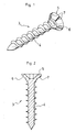
- a device for assembling a rigid part, referred to as insert 1, on a support 2, comprises a screw 3.
- This screw 3 comprises, as represented in particular on the Figures 1 and 2 , a rod 4 extending along an axis, the rod 4 being threaded over at least a part of its length.
- the screw 3 also comprises a screw head 5 adapted to cooperate with a screwdriver, such as an electric screwdriver with torque limiter.
- This screw head 5 may comprise, in known manner, an impression adapted to receive a tool so as to apply the screw pressurization torque. To do this, the screw head 5 can have all types of shapes and dimensions.
- the screw head 5 may be a slotted head, a Phillips head, a Torx head, an Allen head, a countersunk head, etc.
- the screw 3 according to the invention also comprises a surface, said surface 6 of pressure, whose radial dimensions are greater than the radial dimensions of the rod 5.
- This pressure surface 6 is adapted to come into contact with a portion, said portion 12 of contact, said piece 1 reported end screwing.
- the insert 1 includes a slot 13 formed through the insert 1 and defined by the portion 12 of contact. This light has internal dimensions adapted to allow passage of the threaded rod 4 to a contact between the pressure surface 6 of the screw 3 and the contact portion 12 of the insert 1. The length of the rod 4 of the screw 3 must be greater than the thickness of the part 1 reported so that it can be screwed on the support 2.
- the thread of the rod 4 of the screw 3 may have various shapes, helical, trapezoidal, etc. Nevertheless, preferably, the screw 3 has at least one helical thread. According to an advantageous embodiment, the screw 3 has a double helical thread so as to be able to withstand attempts to tear the screw 3 of the support 2 to which it is screwed.
- An assembly device further comprises reliefs and / or conjugated recesses, said mating members, non-symmetrical of revolution with respect to said axis of the rod 4 of the screw, and adapted to fit into the in each other at the end of screwing of the screw 3 so as to increase the torque resistant to screwing.
- the reliefs and hollows may have different shapes and sizes. According to a preferred embodiment, as shown in the figures, the reliefs are ribs 7 and the recesses are notches 8 adapted to receive the ribs 7 at the end of screwing.
- the ribs and indentations are arranged on the pressure surface of the screw and on the contact portion of the insert.
- the contact portion of the insert may comprise ribs and indentations.
- the contact portion 120 comprises only ribs 80.
- the contact portion 12 of the insert 1 includes notches 8 and the pressure surface 6 of the screw head 5 comprises ribs 7 conjugated adapted to be housed in the notches 8 at the end of screwing.
- the pressure surface 6 of the screw head 5 may comprise one or more ribs 7 and the contact portion 12 of the insert may comprise one or more notches 8.
- the number of ribs 7 is smaller than the number of notches 8 so that each rib 7 can fit into a notch.
- the ribs 7 and the indentations 8 are non-symmetrical with respect to the axis of the screw 3.
- the indentations 8 and the ribs 7 preferably extend radially to optimize the increase in torque. resistant to screwing.
- the invention thus makes it possible to significantly improve the quality of an assembly of a rigid part 1 on a support 2, in particular on a support 2 made of a soft material, such as a thermoplastic material, a plaster, an agglomerate, etc. Indeed, a support 2 of a soft material is very sensitive to the torque exerted on a screw when screwing a screw in the latter.
- the distribution of the ribs 7 on the pressure surface 6 of the screw 3 can be of any type.
- the pressure surface 6 of the screw 3 comprises six ribs 7, separated from each other by an angle of 60 degrees. Nevertheless, nothing prevents to provide a different number of ribs 7 and a different distribution.
- the contact portion 120 of an insert 10 comprises only ribs 80 and the pressure surface 60 of the screw head of a screw 30 comprises only notches 70 conjugated to these ribs 80.
- the embedding of the ribs 80 of the contact portion 120 of the insert 10 in the notches 70 of the pressure surface 60 of the screw 30 causes an increase in the torque resistant to screwing, which allows avoid shearing the threads formed in the support by the threaded rod of the screw 30.
- An assembly device allows the assembly of all types of rigid parts on all types of support, particularly on supports of soft material.
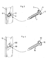
- the figure 6 shows an example of use of such an assembly device on an opening.
- an opening 20 comprises a edge 21 on which a fitting 22 is mounted.
- This fitting 22 extends in a direction, referred to as the longitudinal direction, and comprises two lumens, each lumen being arranged in the vicinity of each of its longitudinal ends.
- Each of the lights is bordered by a contact surface comprising reliefs and / or recesses.
- Each light is adapted to allow the passage of a screw 3 comprising a pressure surface comprising recesses and / or reliefs conjugated to the reliefs and / or recesses of the contact surface bordering this light.
- These reliefs and / or conjugate hollows are adapted to fit into each other at the end of screwing so as to increase the torque resistant screwing, which avoids the shearing of the nets formed in the song 21 of the opening receiving the screws 3.
- an opening according to the invention may comprise other inserts assembled to other supports with assembly devices according to the invention.
- the assembly of an insert on a support by an assembly device can for example be carried out as follows: in a first step, a rigid part to be fixed on a support is positioned on the support and held on the support, for example by the hand of an operator; a screw is then passed through the light of the rigid piece to be fixed; the screw is then held in position through the light, for example, between the fingers of the operator of the hand holding the insert; the operator can then grab a screwdriver, such as an electric screwdriver with torque limiter, and operate the screwdriver so as to screw the screw in the support; at the end of screwing, the recessed members of the screw will fit into the mating members of the rigid part, thus causing an increase in the torque resistant to screwing, which will block the screwdriver; the rigid piece is then assembled to the support with the guarantee that the threads of the screw and the support are not sheared.
- a screwdriver such as an electric screwdriver with torque limiter
- Such an assembly can be realized quickly, by the use, for example, of an electric screwdriver torque limiter, without, however, requiring special precautions, and without risking damaging the threads of the screw or support.
- a device according to the invention is therefore particularly suitable for assembly to the chain of rigid parts on supports, especially for openings.
Abstract
Description
L'invention concerne un dispositif d'assemblage par vis d'au moins une pièce rigide, dite pièce rapportée, sur une pièce réceptrice, dite support. L'invention concerne également un ouvrant -notamment un ouvrant coulissant- comprenant au moins une pièce rigide assemblé sur un support avec un dispositif d'assemblage selon l'invention.The invention relates to a screw assembly device of at least one rigid piece, said insert, on a receiving part, said support. The invention also relates to an opening -including a sliding leaf- comprising at least one rigid part assembled on a support with an assembly device according to the invention.
On connaît déjà depuis fort longtemps des dispositifs d'assemblage par vis d'une pièce, dite pièce rapportée, sur un support, notamment des dispositifs d'assemblage d'une pièce d'ouvrant, tel qu'une ferrure de verrouillage, une tringle de coulissement, etc. sur un ouvrant.We have already known for a long time screw assembly devices of a workpiece, said insert, on a support, including devices for assembling an opening part, such as a lock fitting, a rod sliding, etc. on an opening.
Lors de l'assemblage entre une pièce rapportée et un support, il est nécessaire d'appliquer un couple de serrage qui soit suffisant pour une mise en tension de la vis qui permet la pénétration de la vis dans le support de manière à assurer une liaison rigide et démontable entre la pièce rapportée et le support. La valeur du couple de serrage appliquée conditionne la rigidité de l'assemblage, sa robustesse face aux vibrations, aux variations thermiques, aux chocs, etc. La valeur du couple de serrage à appliquer dépend notamment des frottements du filetage de la vis sur le support, c'est-à-dire notamment du type de vis, du filetage de la vis, du matériau de la vis et du support.When assembling between an insert and a support, it is necessary to apply a tightening torque which is sufficient for a tensioning of the screw which allows the penetration of the screw into the support so as to ensure a connection rigid and removable between the insert and the support. The value of the tightening torque applied determines the rigidity of the assembly, its robustness against vibrations, thermal variations, shocks, etc. The value of the tightening torque to be applied depends in particular on the friction of the threading of the screw on the support, that is to say in particular of the type of screw, the thread of the screw, the material of the screw and the support.
Il est possible de calculer, par des méthodes semi empiriques, préalablement à l'assemblage, une valeur de couple permettant un assemblage optimal de la pièce rapportée sur le support, et de recourir, par exemple, à une clé dynamométrique pour appliquer la valeur du couple de vissage ainsi déterminée. Cette méthode est en réalité peu fiable car la valeur du couple résultant n'est pas connue du fait de paramètres non aisément mesurables au moment du serrage (lubrification des pièces, déformation des pièces, etc.). Il est également possible d'utiliser un limiteur de couple pour ne pas dépasser une valeur prédéterminée. Une telle solution est peu adaptée aux matériaux tendres tels que les matériaux thermoplastiques en raison des faibles valeurs de couple admissibles. En effet, les limiteurs de couple des visseuses électriques industrielles ne permettent pas d'imposer un couple limite suffisamment faible, notamment pour le vissage d'une vis dans un matériau tendre.It is possible to calculate, by semi-empirical methods, prior to assembly, a torque value allowing an optimal assembly of the insert on the support, and to use, for example, a torque wrench to apply the value of the tightening torque thus determined. This method is actually unreliable because the value of the resulting torque is not known because of parameters not easily measurable at the time of tightening (lubrication of parts, deformation of parts, etc.). It is also possible to use a torque limiter not to exceed a predetermined value. Such a solution is not very suitable for soft materials such as thermoplastic materials due to the low allowable torque values. Indeed, torque limiters industrial electric screwdrivers do not allow to impose a sufficiently low torque limit, especially for screwing a screw in a soft material.
Dans la plupart des cas, la valeur du couple appliqué est déterminée au jugé de l'opérateur chargé de l'assemblage.In most cases, the value of the torque applied is determined by the operator in charge of the assembly.
Indépendamment de la méthode utilisée, les conséquences d'un couple mal défini peuvent être très gênantes, voire dangereuses pour certaines applications, notamment les applications d'ouvrant. En particulier, un couple trop faible peut conduire au désassemblage de la pièce rapportée du support ou à un assemblage branlant, et un couple trop fort peut provoquer le cisaillement des filets. Le cisaillement des filets est plus connu dans le langage courant sous le terme de « foirage » de la vis. Ce cisaillement des filets est d'autant plus fréquent que le matériau du support dans lequel la vis est vissée est un matériau tendre, du type bois, cellulose, plâtre, plastique, etc.Regardless of the method used, the consequences of an ill-defined couple can be very inconvenient, even dangerous for certain applications, particularly the applications of opening. In particular, too low a torque can lead to disassembly of the insert of the support or to a shaky assembly, and a too strong torque can cause the shearing of the nets. The shearing of the nets is better known in the common language under the term of "foirage" of the screw. This shearing of the nets is all the more frequent as the material of the support in which the screw is screwed is a soft material, such as wood, cellulose, plaster, plastic, etc.
Un tel dispositif permet donc de limiter la rotation de la vis, en fin de vissage par frottement d'un anneau hélicoïdal solidaire de la vis sur des parois latérales d'un logement de réception de la vis. Un tel dispositif impose donc un usinage précis du logement de réception de la vis suivant des dimensions prédéterminées qui garantissent que l'expansion de l'anneau amène ce dernier en contact bloquant sur les parois latérales du logement de réception. De plus, les parois latérales du logement doivent présenter une surface suffisamment importante pour que les frottements entre l'anneau et ces parois soient suffisants pour bloquer la rotation de la vis dans le logement de réception. Un tel dispositif est donc peu adapté aux pièces fines qui ne permettent pas de ménager un logement de réception dont les parois présente une surface suffisante de contact.Such a device thus makes it possible to limit the rotation of the screw, at the end of screwing by friction of a helical ring secured to the screw on the side walls of a housing for receiving the screw. Such a device therefore requires precise machining of the receiving housing of the screw according to dimensions predetermined that ensure that the expansion of the ring brings the latter into blocking contact on the side walls of the receiving housing. In addition, the side walls of the housing must have a sufficiently large surface so that the friction between the ring and these walls are sufficient to block the rotation of the screw in the receiving housing. Such a device is therefore unsuitable for thin parts that do not allow to provide a receiving housing whose walls have a sufficient contact surface.
De plus, un tel dispositif impose une fixation de l'anneau hélicoïdal sous la tête de vis qui permet d'une part à l'anneau hélicoïdal de s'étendre en fin de vissage et d'autre part de maintenir l'anneau hélicoïdal sous la tête de vis pour faciliter les opérations de manipulation. Cette double fonction est réalisée par un anneau hélicoïdal qui enserre la tête de vis pour pouvoir être solidaire de la vis sans entraver son expansion. Les dimensions de la vis sont donc étroitement liées aux dimensions de l'anneau hélicoïdal. A chaque type de vis correspond donc un type prédéterminé d'anneau hélicoïdal.In addition, such a device imposes a fixing of the helical ring under the screw head which allows on the one hand the helical ring to extend at the end of screwing and secondly to maintain the helical ring under the screw head to facilitate handling operations. This double function is achieved by a helical ring that encloses the screw head to be secured to the screw without hindering its expansion. The dimensions of the screw are closely related to the dimensions of the helical ring. Each type of screw therefore corresponds to a predetermined type of helical ring.
Un tel dispositif doit donc être adapté à chaque application et les modifications de structures imposées ne sont pas négligeables.Such a device must be adapted to each application and the imposed structural changes are not negligible.
Le blocage de la rotation en fin de vissage est également dépendant du coefficient de frottement intrinsèque entre l'anneau hélicoïdal, qui doit présenter des propriétés d'élasticité en compression, et le matériau de la pièce rapportée. Un tel dispositif se prête donc assez mal à la fixation d'une pièce rapportée sur un support en matériau thermoplastique notamment.The locking of the rotation at the end of the screwing is also dependent on the intrinsic coefficient of friction between the helical ring, which must have elastic properties in compression, and the material of the insert. Such a device therefore lends itself badly to the attachment of an insert on a support of thermoplastic material in particular.
L'invention vise à pallier l'ensemble de ces inconvénients et à fournir un dispositif d'assemblage par vis d'une pièce sur un support qui supprime les risques de cisaillement des filets de la vis et/ou du support.The invention aims to overcome all of these disadvantages and to provide a screw assembly device of a part on a support which eliminates the risk of shearing threads of the screw and / or the support.
L'invention vise en particulier à fournir un tel dispositif d'assemblage qui puisse être utilisé et mis en oeuvre sur tous types de matériau.The invention aims in particular to provide such an assembly device that can be used and implemented on all types of material.
L'invention vise aussi à fournir un tel dispositif d'assemblage qui puisse être utilisé sur des supports de toutes épaisseurs.The invention also aims to provide such an assembly device that can be used on supports of any thickness.
L'invention vise également à fournir un tel dispositif d'assemblage qui puisse être produit en grande série sans difficultés particulières.The invention also aims to provide such a device assembly that can be produced in large series without particular difficulties.
L'invention vise également à fournir un tel dispositif d'assemblage qui soit économique à fabriquer et à utiliser.The invention also aims to provide such an assembly device that is economical to manufacture and use.
L'invention vise également à fournir un tel dispositif d'assemblage qui puisse être utilisé par un opérateur sans aptitudes particulières.The invention also aims to provide such an assembly device that can be used by an operator without special skills.
L'invention vise également à fournir un dispositif d'assemblage d'une pièce rigide sur un support qui puisse recourir, pour le vissage de la vis dans le support, à une visseuse électrique industrielle à limiteur de couple standard, sans risque de cisaillement des filets de la vis et/ou du support.The invention also aims at providing a device for assembling a rigid part on a support that can use, for screwing the screw in the support, an industrial electric screwdriver with a standard torque limiter, without the risk of shearing. threads of the screw and / or support.
L'invention vise également à fournir un tel dispositif d'assemblage par vis autotaraudeuse.The invention also aims to provide such an assembly device by self-tapping screw.
L'invention vise également à fournir un ouvrant comprenant au moins une pièce rigide assemblée à au moins un support avec au moins un tel dispositif d'assemblage.The invention also aims to provide an opening comprising at least one rigid part assembled to at least one support with at least one such assembly device.
Pour ce faire, l'invention concerne un dispositif d'assemblage d'au moins une pièce rigide, dite pièce rapportée, sur un support, ledit dispositif d'assemblage comprenant :
- une vis comprenant :
- une tige s'étendant le long d'un axe, ladite tige étant filetée sur au moins une partie de sa longueur,
- une tête de vis adaptée pour coopérer avec un outil de vissage et présentant une surface, dite surface de pression dont les dimensions radiales sont supérieures aux dimensions radiales de ladite tige, ladite surface de pression étant adaptée pour venir en contact d'une portion, dite portion de contact, de ladite pièce rapportée en fin de vissage,
- une lumière ménagée à travers ladite pièce rapportée et délimitée par ladite portion de contact, ladite lumière présentant des dimensions internes adaptées pour permettre un passage de ladite tige filetée jusqu'à un contact entre ladite surface de pression de la vis et ladite portion de contact de la pièce rapportée,
- a screw comprising:
- a rod extending along an axis, said rod being threaded over at least a part of its length,
- a screw head adapted to cooperate with a screwing tool and having a surface, said pressure surface whose radial dimensions are greater than the radial dimensions of said rod, said pressure surface being adapted to come into contact with a portion, so-called contact portion of said insert at the end of screwing,
- a lumen formed through said insert and delimited by said contact portion, said lumen having internal dimensions adapted to allow passage of said threaded rod to a contact between said screw pressure surface and said portion of contact of the patch,
Un dispositif d'assemblage selon l'invention comprend des organes d'encastrement conjugués, non symétriques de révolution, agencés respectivement sous la tête de vis de la vis et sur la pièce rapportée. Dès lors, un dispositif selon l'invention est particulièrement simple à réaliser et n'impose aucune contrainte en terme d'épaisseur de la pièce rapportée.An assembly device according to the invention comprises conjugated rectifying members, non-symmetrical of revolution, respectively arranged under the screw head of the screw and on the insert. Therefore, a device according to the invention is particularly simple to implement and imposes no constraint in terms of thickness of the insert.
Les organes d'encastrement conjugués ont pour fonction d'augmenter le couple résistant au vissage, en fin de vissage de la vis. Dès lors, un opérateur chargé d'assembler une pièce rapportée sur un support avec un tel dispositif d'assemblage, sentira, en fin de vissage, que le couple résistant est nettement plus important qu'avant l'encastrement des organes conjugués. Cette sensation est le signe que l'assemblage est suffisamment serré. De même, une clé dynamométrique indiquera un couple de serrage suffisant, avant le cisaillement des filets. L'encastrement d'organes conjugués les uns dans les autres présente un meilleur pouvoir bloquant que l'augmentation des frottements de surfaces de l'art antérieur. Ces organes d'encastrement sont non symétriques de révolution par rapport à l'axe de la vis pour s'opposer à la rotation de la vis. Ces organes d'encastrement peuvent présenter différentes formes et structures. Ils peuvent également être adaptés au type de matériau dans lequel une pièce rapportée est fixée.The purpose of the mating recessed members is to increase the torque that is resistant to screwing, at the end of screwing of the screw. Therefore, an operator responsible for assembling an insert on a support with such an assembly device will feel, at the end of screwing, that the resisting torque is significantly greater than before the embedding of the conjugate organs. This sensation is a sign that the assembly is sufficiently tight. Similarly, a torque wrench will indicate sufficient torque, before shearing the nets. The embedding of members conjugated with each other has a better blocking power than the increase of surface friction of the prior art. These embedding members are non-symmetrical of revolution relative to the axis of the screw to oppose the rotation of the screw. These embedding members may have different shapes and structures. They can also be adapted to the type of material in which an insert is attached.
Les organes d'encastrement sont formés de reliefs et de creux conjugués. Selon une variante de l'invention, la portion de contact d'une pièce rapportée comprend des reliefs et des creux et la surface de pression de la tête de vis comprend des creux et des reliefs conjugués aux reliefs et creux de la portion de contact.The embedding members are formed of reliefs and conjugate troughs. According to a variant of the invention, the contact portion of an insert comprises reliefs and recesses and the pressure surface of the screw head comprises recesses and reliefs conjugated to the reliefs and recesses of the contact portion.
Selon une autre variante, la portion de contact comprend uniquement des creux et la surface de pression de la tête de vis comprend uniquement des reliefs conjugués à ces creux.According to another variant, the contact portion comprises only recesses and the pressure surface of the screw head comprises only reliefs conjugated to these recesses.
Selon une autre variante, la portion de contact comprend uniquement des reliefs et la surface de pression de la tête de vis comprend uniquement des creux conjugués à ces reliefs.According to another variant, the contact portion comprises only reliefs and the pressure surface of the screw head comprises only recesses conjugated to these reliefs.
Les organes d'encastrement conjugués peuvent présenter différentes formes et dimensions. Ces organes sont adaptés pour s'encastrer les uns dans les autres de manière à augmenter le couple résistant au vissage.The conjugated embedding members may have different shapes and sizes. These members are adapted to fit into each other so as to increase the torque resistant to screwing.
Avantageusement et selon l'invention, lesdits organes d'encastrement agencés sur ladite surface de pression de ladite vis sont des nervures et lesdits organes d'encastrement conjugués agencés sur ladite portion de contact de ladite pièce rapportée sont des échancrures adaptées pour recevoir lesdites nervures en fin de vissage.Advantageously and according to the invention, said embedding members arranged on said pressure surface of said screw are ribs and said conjugate embedding members arranged on said contact portion of said insert are notches adapted to receive said ribs end of screwing.
Selon cette variante de l'invention, les organes d'encastrement de la surface de pression sont des reliefs réalisés par des nervures. Les organes d'encastrement conjugués sont des creux réalisés par des échancrures adaptées pour recevoir les nervures de la surface de pression.According to this variant of the invention, the recessing members of the pressure surface are reliefs made by ribs. The conjugated embedding members are recesses formed by indentations adapted to receive the ribs of the pressure surface.
Avantageusement et selon l'invention, le nombre de nervures de ladite surface de pression de ladite vis est inférieur au nombre d'échancrures de ladite portion de contact de ladite pièce rapportée.Advantageously and according to the invention, the number of ribs of said pressure surface of said screw is less than the number of notches of said contact portion of said insert.
Dès lors, chaque nervure peut venir s'encastrer dans au moins une échancrure.Therefore, each rib can be embedded in at least one indentation.
Les nervures et les échancrures sont non symétriques de révolution par rapport à l'axe de la vis. Les échancrures et les nervures s'étendent de préférence radialement pour optimiser l'augmentation du couple résistant au vissage.The ribs and indentations are non-symmetrical of revolution with respect to the axis of the screw. The indentations and the ribs preferably extend radially to optimize the increase in the torque resistant to screwing.
De plus, il est particulièrement aisé de ménager des échancrures dans une pièce à fixer sur un support qui comprend déjà une lumière de réception d'une vis. Par exemple, ces échancrures peuvent être des petites encoches découpées sur la périphérie de la lumière de la pièce dans lesquelles peuvent venir se loger les nervures ménagées sur la surface de pression de la tête de vis, en fin de vissage.In addition, it is particularly easy to provide notches in a room to fix on a support that already includes a light receiving a screw. For example, these indentations may be small notches cut on the periphery of the room light in which can be housed the ribs formed on the pressure surface of the screw head, at the end of screwing.
De même, il est relativement aisé de fabriquer une vis comprenant des nervures agencées sur la surface de pression d'une vis à partir d'une vis déjà existante.Similarly, it is relatively easy to manufacture a screw comprising ribs arranged on the pressure surface of a screw from an existing screw.
Une vis d'un dispositif d'assemblage selon l'invention peut comprendre une ou plusieurs nervures ménagées sur la surface de pression de la vis. Dans le cas où la surface de pression présente au moins deux nervures, ces dernières peuvent être agencées l'une par rapport à l'autre suivant une variété d'agencements.A screw of an assembly device according to the invention may comprise one or more ribs formed on the pressure surface of the screw. In the case where the pressure surface has at least two ribs, the latter can be arranged relative to each other in a variety of arrangements.
Avantageusement et selon l'invention, lesdites nervures sont régulièrement réparties autour dudit axe de ladite tige filetée.Advantageously and according to the invention, said ribs are regularly distributed around said axis of said threaded rod.
Avantageusement et selon l'invention, ladite surface de pression présente six nervures séparées les unes des autres d'un angle de 60°.Advantageously and according to the invention, said pressure surface has six ribs separated from each other by an angle of 60 °.
Un dispositif selon l'invention permet l'assemblage par vis d'une pièce sur un support qui empêche le cisaillement des filets de la vis. Le support peut comprendre des trous taraudés préalablement au vissage de la vis dans le support. Le support peut également être non préalablement taraudé. Pour ce faire, le support est de préférence réalisé en un matériau tendre, tel qu'un matériau thermoplastique et la vis est une vis autotaraudeuse.A device according to the invention allows the assembly of a piece by screw on a support which prevents the shearing of the threads of the screw. The support may comprise threaded holes prior to screwing the screw into the support. The support can also be unthreaded beforehand. To do this, the support is preferably made of a soft material, such as a thermoplastic material and the screw is a self-tapping screw.
Avantageusement et selon l'invention, ladite vis est une vis autotaraudeuse et ledit support est en matériau tendre non préalablement taraudé au niveau de la zone de réception de ladite vis autotaraudeuse.Advantageously and according to the invention, said screw is a self-tapping screw and said support is of soft material not previously threaded at the receiving zone of said self-tapping screw.
Un dispositif selon l'invention comprenant des organes d'encastrement conjugués agencés respectivement sur une vis autotaraudeuse et sur la portion de contact d'une pièce rapportée est particulièrement efficace et utile pour la fixation de la pièce rapportée sur un support en matériau tendre. En effet, le risque de cisaillement des filets de la vis est d'autant plus important que le matériau du support est tendre.A device according to the invention comprising conjugated embedding members respectively arranged on a self-tapping screw and on the contact portion of an insert is particularly effective and useful for fixing the insert on a support of soft material. Indeed, the risk of shearing the threads of the screw is even more important than the material of the support is soft.
Tous types de vis peuvent servir de base à la réalisation d'une vis d'un dispositif selon l'invention.All types of screws can serve as a basis for producing a screw of a device according to the invention.
Néanmoins, avantageusement et selon l'invention, la vis présente une tige filetée à double filetage hélicoïdale de manière à pouvoir résister aux tentatives d'arrachement de la vis.Nevertheless, advantageously and according to the invention, the screw has a threaded rod double helical thread so as to withstand attempts to tear the screw.
Une tige filetée à double filetage hélicoïdal est une bonne protection à l'arrachement de la vis. Une telle tige est donc particulièrement destinée à un dispositif d'assemblage selon l'invention pour ouvrant aux fins de renforcer l'inviolabilité des espaces clôturés par un tel ouvrant.A threaded rod with double helical thread is a good protection against tearing of the screw. Such a rod is therefore particularly intended for an assembly device according to the invention for opening to reinforce the inviolability of the spaces enclosed by such an opening.
De même, une vis selon l'invention présente de préférence une tige réalisée en un matériau métallique. Néanmoins, selon une variante de l'invention, la vis peut présenter une tige en un matériau du type plastique dur, par exemple pour les assemblages de précision ou pour les assemblages présentant des contraintes particulières de poids.Similarly, a screw according to the invention preferably has a rod made of a metallic material. Nevertheless, according to a variant of the invention, the screw may have a rod made of a material of the hard plastic type, for example for precision assemblies or for assemblies with particular weight constraints.
Une vis selon l'invention comprend une tête de vis adaptée pour coopérer avec un outil de vissage de manière à ce que cet outil puisse imprimer le couple de serrage. La tête de vis peut, par exemple, comprendre une empreinte adaptée pour recevoir un outil de manière à pouvoir appliquer le couple de mise en pression de la vis.A screw according to the invention comprises a screw head adapted to cooperate with a screwing tool so that this tool can print the tightening torque. The screw head may, for example, include a fingerprint adapted to receive a tool so as to apply the screw pressurizing torque.
Pour ce faire, la tête d'une vis selon l'invention peut présenter tous types de formes et de dimensions. La tête de la vis peut être une tête fendue, une tête cruciforme, une tête Torx, une tête à six pans creux ou fraisés, etc.To do this, the head of a screw according to the invention can have all types of shapes and dimensions. The head of the screw may be a slotted head, a Phillips head, a Torx head, a hexagon socket or countersunk head, etc.
L'invention s'étend à un ouvrant coulissant comprenant au moins une pièce rigide assemblée à un support par un dispositif d'assemblage selon l'invention.The invention extends to a sliding leaf comprising at least one rigid piece assembled to a support by an assembly device according to the invention.
Pour ce faire, l'invention concerne aussi un ouvrant - notamment ouvrant coulissant, de porte, fenêtre ou analogue comprenant :
- un cadre formé de profilés creux,
- au moins une pièce, dite support, portée par ledit cadre,
- au moins une pièce rigide assemblée audit support,
- a frame formed of hollow sections,
- at least one piece, said support, carried by said frame,
- at least one rigid part assembled to said support,
Un dispositif d'assemblage selon l'invention permet d'assembler rigidement une pièce rapportée sur un support sans risque de détérioration des filets. Un dispositif selon l'invention est donc particulièrement adapté à l'assemblage de pièces d'ouvrants, notamment d'ouvrants coulissants. Les ouvrants, notamment les ouvrants coulissants, nécessitent des assemblages rigides qui interdisent tout déplacement d'une pièce rapportée par rapport à un support. Surabondamment, les ouvrants sont des structures sensibles d'un bâtiment telle qu'une habitation qui forment la frontière entre l'espace privée et l'espace public. Dès lors, il est important que l'assemblage des différentes pièces qui forment un ouvrant soient rigidement assemblées les unes aux autres. Les couples de serrage doivent donc être correctement appliqués pour déjouer par exemple les tentatives de démontage d'un ouvrant en vue d'une introduction malintentionnée d'un individu dans l'espace privé. De plus, un tel ouvrant doit être suffisamment rigide pour résister aux éventuelles intempéries.An assembly device according to the invention makes it possible to rigidly assemble an insert on a support without risk of deterioration of the threads. A device according to the invention is therefore particularly suitable for assembling parts of openings, in particular sliding doors. The opening, in particular the sliding openings, require rigid assemblies that prohibit any displacement of an insert relative to a support. Surprisingly, the openings are sensitive structures of a building such as a dwelling that form the border between private space and public space. Therefore, it is important that the assembly of the various parts that form an opening are rigidly assembled to each other. Tightening torques must therefore be correctly applied to thwart for example attempts to dismantle an opening for malicious introduction of an individual in the private area. In addition, such an opening must be rigid enough to withstand possible weather.
Par ailleurs, les pièces formant un ouvrant étant relativement nombreuses et peu économiques, il faut s'assurer que les assemblages réalisés n'entraînent pas un cisaillement des filets au risque de devoir reprendre intégralement la réalisation de l'ouvrant, démultipliant ainsi le coût de l'installation d'un tel ouvrant.Furthermore, the parts forming an opening being relatively numerous and uneconomical, it must be ensured that the assemblies made do not cause shearing of the nets at the risk of having to fully resume the production of the opening, thus multiplying the cost of the installation of such an opening.
Un dispositif selon l'invention est donc particulièrement adapté à un ouvrant, notamment à un ouvrant coulissant. Les pièces d'un ouvrant assemblées par un dispositif selon l'invention peuvent être de tous types. Il s'agit, par exemple, d'une têtière assemblée à une garniture d'isolation en un matériau thermoplastique, d'une ferrure montée sur un chant d'un ouvrant, etc.A device according to the invention is therefore particularly suitable for an opening, in particular a sliding leaf. The parts of an opening assembled by a device according to the invention can be of all types. This is, for example, a headrest assembled to an insulating gasket of a thermoplastic material, a fitting mounted on a song of an opening, etc.
Un dispositif selon l'invention permet un assemblage rapide, en grande série, de manière simple et sans prendre de précautions particulières. Par ailleurs, un dispositif selon l'invention permet l'utilisation d'une visseuse électrique standard sans risque de cisaillement des filets de la vis et/ou du support. Un dispositif selon l'invention permet donc de réduire les coûts de fabrication d'un ouvrant selon l'invention.A device according to the invention allows an assembly fast, in large series, in a simple way and without taking special precautions. Furthermore, a device according to the invention allows the use of a standard electric screwdriver without risk of shear threads of the screw and / or support. A device according to the invention thus makes it possible to reduce the manufacturing costs of an opening according to the invention.
L'invention concerne en outre un dispositif d'assemblage par vis d'une pièce rapportée sur un support et un ouvrant comprenant au moins une pièce rigide assemblée sur un support par un tel dispositif d'assemblage caractérisés en combinaison par tout ou partie des caractéristiques mentionnées ci-dessus ou ci-après.The invention furthermore relates to a device for assembling by screws an insert on a support and an opening comprising at least one rigid part assembled on a support by such an assembly device, characterized in combination by all or some of the features. mentioned above or below.
D'autres caractéristiques, buts et avantages de l'invention apparaîtront à la lecture de la description suivante qui présente à titre d'exemple non limitatif un mode de réalisation de l'invention, en référence aux dessins annexés ; sur ces dessins :
- la
figure 1 est une vue schématique en perspective d'une vis d'un dispositif d'assemblage selon un mode de réalisation de l'invention, - la
figure 2 est une vue schématique en coupe d'une vis d'un dispositif d'assemblage selon un mode de réalisation de l'invention, - la
figure 3 est une vue schématique en perspective éclatée d'un dispositif d'assemblage selon un mode de réalisation de l'invention comprenant une vis et une pièce rigide, - la
figure 4 est une vue schématique en perspective éclatée d'un dispositif d'assemblage selon un autre mode de réalisation de l'invention comprenant une vis et une pièce rigide, - la
figure 5 est une vue schématique en coupe d'une pièce rigide assemblée sur un support par un dispositif d'assemblage selon un mode de réalisation de l'invention, - la
figure 6 est une vue schématique d'une porte selon un mode de réalisation de l'invention comprenant une ferrure assemblée au chant d'une porte par un dispositif d'assemblage selon l'invention.
- the
figure 1 is a schematic perspective view of a screw of an assembly device according to one embodiment of the invention, - the
figure 2 is a diagrammatic sectional view of a screw of an assembly device according to one embodiment of the invention, - the
figure 3 is a schematic perspective exploded view of an assembly device according to an embodiment of the invention comprising a screw and a rigid part, - the
figure 4 is a schematic perspective exploded view of an assembly device according to another embodiment of the invention comprising a screw and a rigid part, - the
figure 5 is a schematic sectional view of a rigid part assembled on a support by an assembly device according to one embodiment of the invention, - the
figure 6 is a schematic view of a door according to one embodiment of the invention comprising a fitting assembled to the edge of a door by an assembly device according to the invention.
Selon l'invention et tel que représenté sur la
Cette vis 3 comprend, tel que représenté notamment sur les
Cette tête 5 de vis peut comprendre, de manière connue, une empreinte adaptée pour recevoir un outil de manière à pouvoir appliquer le couple de mise en pression de la vis. Pour ce faire, la tête 5 de vis peut présenter tous types de formes et de dimensions. La tête 5 de vis peut être une tête fendue, une tête cruciforme, une tête Torx, une tête à six pans creux, une tête fraisée, etc.This
La vis 3 selon l'invention comprend également une surface, dite surface 6 de pression, dont les dimensions radiales sont supérieures aux dimensions radiales de la tige 5. Cette surface 6 de pression est adaptée pour venir en contact d'une portion, dite portion 12 de contact, de ladite pièce 1 rapportée en fin de vissage.The screw 3 according to the invention also comprises a surface, said
La pièce 1 rapportée comprend une lumière 13 ménagée à travers la pièce 1 rapportée et délimitée par la portion 12 de contact. Cette lumière présente des dimensions internes adaptées pour permettre un passage de la tige 4 filetée jusqu'à un contact entre la surface 6 de pression de la vis 3 et la portion 12 de contact de la pièce 1 rapportée. La longueur de la tige 4 de la vis 3 doit être supérieure à l'épaisseur de la pièce 1 rapportée pour qu'elle puisse être vissée sur le support 2.The insert 1 includes a
Le filetage de la tige 4 de la vis 3 peut présenter diverses formes, hélicoïdale, trapézoïdale, etc. Néanmoins, de préférence, la vis 3 présente au moins un filet hélicoïdal. Selon un mode de réalisation avantageux, la vis 3 présente un double filet hélicoïdal de manière à pouvoir efficacement résister aux tentatives d'arrachage de la vis 3 du support 2 auquel elle est vissée.The thread of the rod 4 of the screw 3 may have various shapes, helical, trapezoidal, etc. Nevertheless, preferably, the screw 3 has at least one helical thread. According to an advantageous embodiment, the screw 3 has a double helical thread so as to be able to withstand attempts to tear the screw 3 of the support 2 to which it is screwed.
Un dispositif d'assemblage selon l'invention comprend en outre des reliefs et/ou renfoncements conjugués, dits organes d'encastrement conjugués, non symétriques de révolution par rapport audit axe de la tige 4 de la vis, et adaptés pour s'encastrer les uns dans les autres en fin de vissage de la vis 3 de manière à augmenter le couple résistant au vissage.An assembly device according to the invention further comprises reliefs and / or conjugated recesses, said mating members, non-symmetrical of revolution with respect to said axis of the rod 4 of the screw, and adapted to fit into the in each other at the end of screwing of the screw 3 so as to increase the torque resistant to screwing.
Les reliefs et creux peuvent présenter différentes formes et dimensions. Selon un mode de réalisation préférentiel, tel que représenté sur les figures, les reliefs sont des nervures 7 et les creux sont des échancrures 8 adaptées pour recevoir les nervures 7 en fin de vissage.The reliefs and hollows may have different shapes and sizes. According to a preferred embodiment, as shown in the figures, the reliefs are
Les nervures et les échancrures sont agencées sur la surface de pression de la vis et sur la portion de contact de la pièce rapportée.The ribs and indentations are arranged on the pressure surface of the screw and on the contact portion of the insert.
Selon un mode de réalisation non représenté sur les figures, la portion de contact de la pièce rapportée peut comprendre des nervures et des échancrures.According to an embodiment not shown in the figures, the contact portion of the insert may comprise ribs and indentations.
Selon un autre mode de réalisation tel que représenté sur la
Selon une variante de l'invention, tel que représenté sur la
La surface 6 de pression de la tête 5 de vis peut comprendre une ou plusieurs nervures 7 et la portion 12 de contact de la pièce rapportée peut comprendre une ou plusieurs échancrures 8.The
De préférence, le nombre de nervures 7 est inférieur au nombre d'échancrures 8 de manière à ce que chaque nervure 7 puisse s'encastrer dans une échancrure.Preferably, the number of
Les nervures 7 et les échancrures 8 sont non symétriques de révolution par rapport à l'axe de la vis 3. Les échancrures 8 et les nervures 7 s'étendent de préférence radialement pour optimiser l'augmentation du couple résistant au vissage.The
Lorsque les nervures 7 s'encastrent dans les échancrures 8, le couple résistant au vissage augmente de manière significative, ce qui permet d'empêcher le cisaillement des filets ménagés par la vis 3 dans le support 2. Un dispositif d'assemblage selon l'invention permet donc d'améliorer significativement la qualité d'un assemblage d'une pièce 1 rigide sur un support 2, notamment sur un support 2 en un matériau tendre, tel qu'un matériau thermoplastique, un plâtre, un aggloméré, etc. En effet, un support 2 en un matériau tendre est très sensible au couple exercé sur une vis lors du vissage d'une vis dans ce dernier.When the
La répartition des nervures 7 sur la surface de pression 6 de la vis 3 peut être de tout type.The distribution of the
Selon un mode de réalisation, la surface 6 de pression de la vis 3 comprend six nervures 7, séparées les unes des autres d'un angle de 60 degrés. Néanmoins, rien n'empêche de prévoir un nombre différent de nervures 7 et une répartition différente.According to one embodiment, the
Selon un autre mode de réalisation, et tel que représenté sur la
Selon ce mode de réalisation, l'encastrement des nervures 80 de la portion 120 de contact de la pièce 10 rapportée dans les échancrures 70 de la surface de pression 60 de la vis 30 provoque une augmentation du couple résistant au vissage, ce qui permet d'éviter le cisaillement des filets ménagés dans le support par la tige filetée de la vis 30.According to this embodiment, the embedding of the
Un dispositif d'assemblage selon l'invention permet l'assemblage de tous types de pièces rigides sur tous types de support, notamment sur des supports en matériau tendre.An assembly device according to the invention allows the assembly of all types of rigid parts on all types of support, particularly on supports of soft material.
La
Selon ce mode de réalisation, un ouvrant 20 comprend un chant 21 sur lequel est monté une ferrure 22. Cette ferrure 22 s'étend selon une direction, dite direction longitudinale, et comprend deux lumières, chaque lumière étant agencée au voisinage de chacune de ses extrémités longitudinales. Chacune des lumières est bordée d'une surface de contact comprenant des reliefs et/ou creux. Chaque lumière est adaptée pour permettre le passage d'une vis 3 comprenant une surface de pression comprenant des creux et/ou reliefs conjugués aux reliefs et/ou creux de la surface de contact bordant cette lumière. Ces reliefs et/ou creux conjugués sont adaptés pour s'encastrer les uns dans les autres en fin de vissage de manière à augmenter le couple résistant au vissage, ce qui permet d'éviter le cisaillement des filets ménagés dans le chant 21 de l'ouvrant recevant les vis 3.According to this embodiment, an
Bien entendu, un ouvrant selon l'invention peut comprendre d'autres pièces rapportées assemblées à d'autres supports avec des dispositifs d'assemblage selon l'invention.Of course, an opening according to the invention may comprise other inserts assembled to other supports with assembly devices according to the invention.
L'assemblage d'une pièce rapportée sur un support par un dispositif d'assemblage selon l'invention peut par exemple est réalisé de la façon suivante : dans une première étape, une pièce rigide à fixer sur un support est positionnée sur le support et maintenu sur le support, par exemple par la main d'un opérateur ; une vis est ensuite passée à travers la lumière de la pièce rigide à fixer ; la vis est ensuite maintenue en position à travers la lumière, par exemple, entre les doigts de l'opérateur de la main qui maintient la pièce rapportée ; l'opérateur peut ensuite se saisir d'un outil de vissage, tel qu'une visseuse électrique à limiteur de couple, et actionner la visseuse de manière à visser la vis dans le support ; en fin de vissage, les organes d'encastrement de la vis vont s'encastrer dans les organes d'encastrement conjugués de la pièce rigide, provoquant ainsi une augmentation du couple résistant au vissage, ce qui va bloquer la visseuse ; la pièce rigide est alors assemblée au support avec la garantie que les filets de la vis et du support ne sont pas cisaillés.The assembly of an insert on a support by an assembly device according to the invention can for example be carried out as follows: in a first step, a rigid part to be fixed on a support is positioned on the support and held on the support, for example by the hand of an operator; a screw is then passed through the light of the rigid piece to be fixed; the screw is then held in position through the light, for example, between the fingers of the operator of the hand holding the insert; the operator can then grab a screwdriver, such as an electric screwdriver with torque limiter, and operate the screwdriver so as to screw the screw in the support; at the end of screwing, the recessed members of the screw will fit into the mating members of the rigid part, thus causing an increase in the torque resistant to screwing, which will block the screwdriver; the rigid piece is then assembled to the support with the guarantee that the threads of the screw and the support are not sheared.
Un tel assemblage peut être réalisé rapidement, par l'utilisation, par exemple, d'une visseuse électrique à limiteur de couple, sans néanmoins nécessiter de précautions particulières, et sans risquer de détériorer les filets de la vis ou du support.Such an assembly can be realized quickly, by the use, for example, of an electric screwdriver torque limiter, without, however, requiring special precautions, and without risking damaging the threads of the screw or support.
Un dispositif selon l'invention est donc particulièrement adapté à l'assemblage à la chaîne de pièces rigides sur des supports, notamment pour des ouvrants.A device according to the invention is therefore particularly suitable for assembly to the chain of rigid parts on supports, especially for openings.
Claims (10)
Applications Claiming Priority (1)
| Application Number | Priority Date | Filing Date | Title |
|---|---|---|---|
| FR0702303A FR2914379B1 (en) | 2007-03-29 | 2007-03-29 | DEVICE FOR ASSEMBLING A SCREW OF AT LEAST ONE WORKPIECE ON A SUPPORT AND OPENING EQUIPPED WITH SUCH A DEVICE. |
Publications (2)
| Publication Number | Publication Date |
|---|---|
| EP1975420A1 true EP1975420A1 (en) | 2008-10-01 |
| EP1975420B1 EP1975420B1 (en) | 2013-05-08 |
Family
ID=38626586
Family Applications (1)
| Application Number | Title | Priority Date | Filing Date |
|---|---|---|---|
| EP08152790.5A Active EP1975420B1 (en) | 2007-03-29 | 2008-03-14 | Device for screw assembly of at least one rigid part on a support and opening equipped with such a device |
Country Status (2)
| Country | Link |
|---|---|
| EP (1) | EP1975420B1 (en) |
| FR (1) | FR2914379B1 (en) |
Cited By (4)
| Publication number | Priority date | Publication date | Assignee | Title |
|---|---|---|---|---|
| ITTV20120113A1 (en) * | 2012-06-12 | 2013-12-13 | Scarpa Calzaturificio Spa | SKI BOOT |
| TWI620878B (en) * | 2017-11-10 | 2018-04-11 | Self-tapping screw head structure | |
| CN111352331A (en) * | 2018-12-21 | 2020-06-30 | 伊塔瑞士钟表制造股份有限公司 | Assembly comprising a support, a main plate and a fastening device, in particular for a timepiece |
| WO2023280614A1 (en) * | 2021-07-06 | 2023-01-12 | Robert Bosch Gmbh | Fastening arrangement for fastening two objects to each other |
Families Citing this family (1)
| Publication number | Priority date | Publication date | Assignee | Title |
|---|---|---|---|---|
| DE102013211864B4 (en) * | 2013-06-21 | 2019-05-23 | PHI Technik für Fenster und Türen GmbH | Arrangement for fixing a post to a plastic frame strip of a window or a door by means of a post connector made of plastic |
Citations (6)
| Publication number | Priority date | Publication date | Assignee | Title |
|---|---|---|---|---|
| US4339179A (en) * | 1979-05-22 | 1982-07-13 | Essilor International "Cie Generale D'optique" | Eyeglass frame having open rims closed by self-locking screw assemblies with dog clutch means |
| EP0530585A2 (en) * | 1991-09-03 | 1993-03-10 | Synthes AG, Chur | Self-locking resorbable screws and plates for internal fixation of bone fractures and tendon-to-bone attachment |
| US5199839A (en) * | 1991-10-09 | 1993-04-06 | Abbott-Interfast Corporation | Fastener screw having improved installation and self-locking characteristics |
| JP2005273702A (en) * | 2004-03-23 | 2005-10-06 | Hitachi Ltd | Fastening structure for screw |
| FR2883343A1 (en) | 2005-03-18 | 2006-09-22 | Arco Richard Daniel D | Screw locking limitation device, has screw and helical ring assembly screwed in part till screw contacts with part to be locked, where ring is forced in housing by utilizing screw stopper, so as to block rotation of screw |
| GB2429039A (en) * | 2005-08-12 | 2007-02-14 | Assa Abloy Ltd | Lock assembly with first and second return spring assemblies acting on handle |
-
2007
- 2007-03-29 FR FR0702303A patent/FR2914379B1/en not_active Expired - Fee Related
-
2008
- 2008-03-14 EP EP08152790.5A patent/EP1975420B1/en active Active
Patent Citations (6)
| Publication number | Priority date | Publication date | Assignee | Title |
|---|---|---|---|---|
| US4339179A (en) * | 1979-05-22 | 1982-07-13 | Essilor International "Cie Generale D'optique" | Eyeglass frame having open rims closed by self-locking screw assemblies with dog clutch means |
| EP0530585A2 (en) * | 1991-09-03 | 1993-03-10 | Synthes AG, Chur | Self-locking resorbable screws and plates for internal fixation of bone fractures and tendon-to-bone attachment |
| US5199839A (en) * | 1991-10-09 | 1993-04-06 | Abbott-Interfast Corporation | Fastener screw having improved installation and self-locking characteristics |
| JP2005273702A (en) * | 2004-03-23 | 2005-10-06 | Hitachi Ltd | Fastening structure for screw |
| FR2883343A1 (en) | 2005-03-18 | 2006-09-22 | Arco Richard Daniel D | Screw locking limitation device, has screw and helical ring assembly screwed in part till screw contacts with part to be locked, where ring is forced in housing by utilizing screw stopper, so as to block rotation of screw |
| GB2429039A (en) * | 2005-08-12 | 2007-02-14 | Assa Abloy Ltd | Lock assembly with first and second return spring assemblies acting on handle |
Cited By (4)
| Publication number | Priority date | Publication date | Assignee | Title |
|---|---|---|---|---|
| ITTV20120113A1 (en) * | 2012-06-12 | 2013-12-13 | Scarpa Calzaturificio Spa | SKI BOOT |
| TWI620878B (en) * | 2017-11-10 | 2018-04-11 | Self-tapping screw head structure | |
| CN111352331A (en) * | 2018-12-21 | 2020-06-30 | 伊塔瑞士钟表制造股份有限公司 | Assembly comprising a support, a main plate and a fastening device, in particular for a timepiece |
| WO2023280614A1 (en) * | 2021-07-06 | 2023-01-12 | Robert Bosch Gmbh | Fastening arrangement for fastening two objects to each other |
Also Published As
| Publication number | Publication date |
|---|---|
| FR2914379A1 (en) | 2008-10-03 |
| EP1975420B1 (en) | 2013-05-08 |
| FR2914379B1 (en) | 2011-07-15 |
Similar Documents
| Publication | Publication Date | Title |
|---|---|---|
| EP2702280B1 (en) | Blind rivet bolt | |
| EP1975420B1 (en) | Device for screw assembly of at least one rigid part on a support and opening equipped with such a device | |
| FR2907859A1 (en) | Bolt assembly e.g. for securing electrical conductor, has recesses on threaded portion of bolt, to engage with tabs of ring on shank, for ensuring rotation locking of ring with respect to threaded portion | |
| EP2917969B1 (en) | Device for fixing an electrical connection terminal to a support | |
| FR2979648A1 (en) | MECHANICAL SYSTEM COMPRISING A DEVICE FOR CONNECTION BETWEEN A WEAR PIECE AND ITS SUPPORT, PUBLIC WORKS MACHINE BUCKET AND METHOD OF IMPLEMENTING SUCH A SYSTEM | |
| FR2979646A1 (en) | MECHANICAL SYSTEM COMPRISING A DEVICE FOR CONNECTION BETWEEN A WEAR PIECE AND ITS SUPPORT, PUBLIC WORKS MACHINE BUCKET AND METHOD OF IMPLEMENTING SUCH A SYSTEM | |
| EP2571113B1 (en) | Attachment and quick-connection device for a two-part connector | |
| WO2019162146A1 (en) | Retaining device for a threaded member, in particular for a nut | |
| EP1878927B1 (en) | Dryable die cast nut and part die cast with such a nut | |
| FR2560100A3 (en) | Screwing end piece for screws or nuts with a limited tightening torque | |
| WO2019063646A1 (en) | Nut-locking device and associated assembly unit | |
| EP1174576B1 (en) | Torque control hinge | |
| EP1231422A1 (en) | Process for making a screw unloseable, fixation collars for pipes and use of the process to manufacture the collars | |
| EP3559482B1 (en) | Separating device which can be arranged between two mountings | |
| EP2694826A1 (en) | Device for securing an assembly screw to an element before being fixed to another element | |
| EP3859170B1 (en) | Bolt comprising a nut and at least one washer obtained by hardening of a pasty material, method for installing said bolt and assembly comprising at least one such bolt | |
| EP3227571B1 (en) | Fastener with torque limitation | |
| FR2896551A1 (en) | ANCHORING ANKLE FOR FRIENDLY MATERIAL | |
| WO2019158486A1 (en) | Braking device comprising an element for provisionally holding a brake disc on a hub | |
| CH601684A5 (en) | Fixing screw for spectacles | |
| WO2006030083A1 (en) | Device for setting and screwing an element for fixing a thermal insulation coating on a support structure | |
| FR3006019A1 (en) | FIXING DEVICE, FIXING ASSEMBLY AND VEHICLE COMPRISING SUCH A FIXING DEVICE | |
| FR2918912A1 (en) | Screwing bush for transverse wing screw of optical block element, has screw head comprising transverse wings, where selected part of wing is engaged in housing so as to be retained and supported against edge surface in screwing position | |
| FR2876532A1 (en) | DISPLAY DEVICE WITH CATHODE TUBE AND CORRESPONDING FASTENING SYSTEM | |
| FR2792689A1 (en) | Screw fixing insert has threaded bore for receiving screw and is clipped into housing in one part to be fixed |
Legal Events
| Date | Code | Title | Description |
|---|---|---|---|
| PUAI | Public reference made under article 153(3) epc to a published international application that has entered the european phase |
Free format text: ORIGINAL CODE: 0009012 |
|
| AK | Designated contracting states |
Kind code of ref document: A1 Designated state(s): AT BE BG CH CY CZ DE DK EE ES FI FR GB GR HR HU IE IS IT LI LT LU LV MC MT NL NO PL PT RO SE SI SK TR |
|
| AX | Request for extension of the european patent |
Extension state: AL BA MK RS |
|
| 17P | Request for examination filed |
Effective date: 20090210 |
|
| 17Q | First examination report despatched |
Effective date: 20090408 |
|
| AKX | Designation fees paid |
Designated state(s): AT BE BG CH CY CZ DE DK EE ES FI FR GB GR HR HU IE IS IT LI LT LU LV MC MT NL NO PL PT RO SE SI SK TR |
|
| GRAP | Despatch of communication of intention to grant a patent |
Free format text: ORIGINAL CODE: EPIDOSNIGR1 |
|
| RIC1 | Information provided on ipc code assigned before grant |
Ipc: F16B 35/06 20060101ALI20121128BHEP Ipc: F16B 5/02 20060101AFI20121128BHEP Ipc: F16B 39/282 20060101ALI20121128BHEP Ipc: E05B 9/00 20060101ALI20121128BHEP |
|
| GRAS | Grant fee paid |
Free format text: ORIGINAL CODE: EPIDOSNIGR3 |
|
| GRAA | (expected) grant |
Free format text: ORIGINAL CODE: 0009210 |
|
| AK | Designated contracting states |
Kind code of ref document: B1 Designated state(s): AT BE BG CH CY CZ DE DK EE ES FI FR GB GR HR HU IE IS IT LI LT LU LV MC MT NL NO PL PT RO SE SI SK TR |
|
| REG | Reference to a national code |
Ref country code: GB Ref legal event code: FG4D Free format text: NOT ENGLISH |
|
| REG | Reference to a national code |
Ref country code: AT Ref legal event code: REF Ref document number: 611239 Country of ref document: AT Kind code of ref document: T Effective date: 20130515 Ref country code: CH Ref legal event code: EP |
|
| REG | Reference to a national code |
Ref country code: IE Ref legal event code: FG4D Free format text: LANGUAGE OF EP DOCUMENT: FRENCH |
|
| REG | Reference to a national code |
Ref country code: DE Ref legal event code: R096 Ref document number: 602008024388 Country of ref document: DE Effective date: 20130704 |
|
| REG | Reference to a national code |
Ref country code: AT Ref legal event code: MK05 Ref document number: 611239 Country of ref document: AT Kind code of ref document: T Effective date: 20130508 |
|
| REG | Reference to a national code |
Ref country code: LT Ref legal event code: MG4D |
|
| REG | Reference to a national code |
Ref country code: NL Ref legal event code: VDEP Effective date: 20130508 |
|
| PG25 | Lapsed in a contracting state [announced via postgrant information from national office to epo] |
Ref country code: ES Free format text: LAPSE BECAUSE OF FAILURE TO SUBMIT A TRANSLATION OF THE DESCRIPTION OR TO PAY THE FEE WITHIN THE PRESCRIBED TIME-LIMIT Effective date: 20130819 Ref country code: LT Free format text: LAPSE BECAUSE OF FAILURE TO SUBMIT A TRANSLATION OF THE DESCRIPTION OR TO PAY THE FEE WITHIN THE PRESCRIBED TIME-LIMIT Effective date: 20130508 Ref country code: SE Free format text: LAPSE BECAUSE OF FAILURE TO SUBMIT A TRANSLATION OF THE DESCRIPTION OR TO PAY THE FEE WITHIN THE PRESCRIBED TIME-LIMIT Effective date: 20130508 Ref country code: IS Free format text: LAPSE BECAUSE OF FAILURE TO SUBMIT A TRANSLATION OF THE DESCRIPTION OR TO PAY THE FEE WITHIN THE PRESCRIBED TIME-LIMIT Effective date: 20130908 Ref country code: NO Free format text: LAPSE BECAUSE OF FAILURE TO SUBMIT A TRANSLATION OF THE DESCRIPTION OR TO PAY THE FEE WITHIN THE PRESCRIBED TIME-LIMIT Effective date: 20130808 Ref country code: AT Free format text: LAPSE BECAUSE OF FAILURE TO SUBMIT A TRANSLATION OF THE DESCRIPTION OR TO PAY THE FEE WITHIN THE PRESCRIBED TIME-LIMIT Effective date: 20130508 Ref country code: SI Free format text: LAPSE BECAUSE OF FAILURE TO SUBMIT A TRANSLATION OF THE DESCRIPTION OR TO PAY THE FEE WITHIN THE PRESCRIBED TIME-LIMIT Effective date: 20130508 Ref country code: PT Free format text: LAPSE BECAUSE OF FAILURE TO SUBMIT A TRANSLATION OF THE DESCRIPTION OR TO PAY THE FEE WITHIN THE PRESCRIBED TIME-LIMIT Effective date: 20130909 Ref country code: GR Free format text: LAPSE BECAUSE OF FAILURE TO SUBMIT A TRANSLATION OF THE DESCRIPTION OR TO PAY THE FEE WITHIN THE PRESCRIBED TIME-LIMIT Effective date: 20130809 Ref country code: FI Free format text: LAPSE BECAUSE OF FAILURE TO SUBMIT A TRANSLATION OF THE DESCRIPTION OR TO PAY THE FEE WITHIN THE PRESCRIBED TIME-LIMIT Effective date: 20130508 |
|
| PG25 | Lapsed in a contracting state [announced via postgrant information from national office to epo] |
Ref country code: HR Free format text: LAPSE BECAUSE OF FAILURE TO SUBMIT A TRANSLATION OF THE DESCRIPTION OR TO PAY THE FEE WITHIN THE PRESCRIBED TIME-LIMIT Effective date: 20130508 Ref country code: PL Free format text: LAPSE BECAUSE OF FAILURE TO SUBMIT A TRANSLATION OF THE DESCRIPTION OR TO PAY THE FEE WITHIN THE PRESCRIBED TIME-LIMIT Effective date: 20130508 Ref country code: BG Free format text: LAPSE BECAUSE OF FAILURE TO SUBMIT A TRANSLATION OF THE DESCRIPTION OR TO PAY THE FEE WITHIN THE PRESCRIBED TIME-LIMIT Effective date: 20130808 Ref country code: CY Free format text: LAPSE BECAUSE OF FAILURE TO SUBMIT A TRANSLATION OF THE DESCRIPTION OR TO PAY THE FEE WITHIN THE PRESCRIBED TIME-LIMIT Effective date: 20130508 |
|
| PG25 | Lapsed in a contracting state [announced via postgrant information from national office to epo] |
Ref country code: LV Free format text: LAPSE BECAUSE OF FAILURE TO SUBMIT A TRANSLATION OF THE DESCRIPTION OR TO PAY THE FEE WITHIN THE PRESCRIBED TIME-LIMIT Effective date: 20130508 |
|
| PG25 | Lapsed in a contracting state [announced via postgrant information from national office to epo] |
Ref country code: SK Free format text: LAPSE BECAUSE OF FAILURE TO SUBMIT A TRANSLATION OF THE DESCRIPTION OR TO PAY THE FEE WITHIN THE PRESCRIBED TIME-LIMIT Effective date: 20130508 Ref country code: CZ Free format text: LAPSE BECAUSE OF FAILURE TO SUBMIT A TRANSLATION OF THE DESCRIPTION OR TO PAY THE FEE WITHIN THE PRESCRIBED TIME-LIMIT Effective date: 20130508 Ref country code: EE Free format text: LAPSE BECAUSE OF FAILURE TO SUBMIT A TRANSLATION OF THE DESCRIPTION OR TO PAY THE FEE WITHIN THE PRESCRIBED TIME-LIMIT Effective date: 20130508 Ref country code: DK Free format text: LAPSE BECAUSE OF FAILURE TO SUBMIT A TRANSLATION OF THE DESCRIPTION OR TO PAY THE FEE WITHIN THE PRESCRIBED TIME-LIMIT Effective date: 20130508 |
|
| PG25 | Lapsed in a contracting state [announced via postgrant information from national office to epo] |
Ref country code: IT Free format text: LAPSE BECAUSE OF FAILURE TO SUBMIT A TRANSLATION OF THE DESCRIPTION OR TO PAY THE FEE WITHIN THE PRESCRIBED TIME-LIMIT Effective date: 20130508 Ref country code: RO Free format text: LAPSE BECAUSE OF FAILURE TO SUBMIT A TRANSLATION OF THE DESCRIPTION OR TO PAY THE FEE WITHIN THE PRESCRIBED TIME-LIMIT Effective date: 20130508 Ref country code: NL Free format text: LAPSE BECAUSE OF FAILURE TO SUBMIT A TRANSLATION OF THE DESCRIPTION OR TO PAY THE FEE WITHIN THE PRESCRIBED TIME-LIMIT Effective date: 20130508 |
|
| PLBE | No opposition filed within time limit |
Free format text: ORIGINAL CODE: 0009261 |
|
| STAA | Information on the status of an ep patent application or granted ep patent |
Free format text: STATUS: NO OPPOSITION FILED WITHIN TIME LIMIT |
|
| 26N | No opposition filed |
Effective date: 20140211 |
|
| REG | Reference to a national code |
Ref country code: DE Ref legal event code: R097 Ref document number: 602008024388 Country of ref document: DE Effective date: 20140211 |
|
| REG | Reference to a national code |
Ref country code: DE Ref legal event code: R119 Ref document number: 602008024388 Country of ref document: DE |
|
| PG25 | Lapsed in a contracting state [announced via postgrant information from national office to epo] |
Ref country code: LU Free format text: LAPSE BECAUSE OF FAILURE TO SUBMIT A TRANSLATION OF THE DESCRIPTION OR TO PAY THE FEE WITHIN THE PRESCRIBED TIME-LIMIT Effective date: 20140314 |
|
| REG | Reference to a national code |
Ref country code: CH Ref legal event code: PL |
|
| GBPC | Gb: european patent ceased through non-payment of renewal fee |
Effective date: 20140314 |
|
| REG | Reference to a national code |
Ref country code: IE Ref legal event code: MM4A |
|
| REG | Reference to a national code |
Ref country code: DE Ref legal event code: R119 Ref document number: 602008024388 Country of ref document: DE Effective date: 20141001 |
|
| PG25 | Lapsed in a contracting state [announced via postgrant information from national office to epo] |
Ref country code: IE Free format text: LAPSE BECAUSE OF NON-PAYMENT OF DUE FEES Effective date: 20140314 Ref country code: CH Free format text: LAPSE BECAUSE OF NON-PAYMENT OF DUE FEES Effective date: 20140331 Ref country code: GB Free format text: LAPSE BECAUSE OF NON-PAYMENT OF DUE FEES Effective date: 20140314 Ref country code: DE Free format text: LAPSE BECAUSE OF NON-PAYMENT OF DUE FEES Effective date: 20141001 Ref country code: LI Free format text: LAPSE BECAUSE OF NON-PAYMENT OF DUE FEES Effective date: 20140331 |
|
| PG25 | Lapsed in a contracting state [announced via postgrant information from national office to epo] |
Ref country code: MT Free format text: LAPSE BECAUSE OF FAILURE TO SUBMIT A TRANSLATION OF THE DESCRIPTION OR TO PAY THE FEE WITHIN THE PRESCRIBED TIME-LIMIT Effective date: 20130508 |
|
| REG | Reference to a national code |
Ref country code: FR Ref legal event code: PLFP Year of fee payment: 9 |
|
| PG25 | Lapsed in a contracting state [announced via postgrant information from national office to epo] |
Ref country code: MC Free format text: LAPSE BECAUSE OF FAILURE TO SUBMIT A TRANSLATION OF THE DESCRIPTION OR TO PAY THE FEE WITHIN THE PRESCRIBED TIME-LIMIT Effective date: 20130508 |
|
| PG25 | Lapsed in a contracting state [announced via postgrant information from national office to epo] |
Ref country code: TR Free format text: LAPSE BECAUSE OF FAILURE TO SUBMIT A TRANSLATION OF THE DESCRIPTION OR TO PAY THE FEE WITHIN THE PRESCRIBED TIME-LIMIT Effective date: 20130508 Ref country code: HU Free format text: LAPSE BECAUSE OF FAILURE TO SUBMIT A TRANSLATION OF THE DESCRIPTION OR TO PAY THE FEE WITHIN THE PRESCRIBED TIME-LIMIT; INVALID AB INITIO Effective date: 20080314 |
|
| REG | Reference to a national code |
Ref country code: FR Ref legal event code: PLFP Year of fee payment: 10 |
|
| PG25 | Lapsed in a contracting state [announced via postgrant information from national office to epo] |
Ref country code: BE Free format text: LAPSE BECAUSE OF NON-PAYMENT OF DUE FEES Effective date: 20140331 |
|
| REG | Reference to a national code |
Ref country code: FR Ref legal event code: PLFP Year of fee payment: 11 |
|
| PGFP | Annual fee paid to national office [announced via postgrant information from national office to epo] |
Ref country code: FR Payment date: 20230214 Year of fee payment: 16 |