EP1969995A1 - Eye testing device - Google Patents
Eye testing device Download PDFInfo
- Publication number
- EP1969995A1 EP1969995A1 EP07405084A EP07405084A EP1969995A1 EP 1969995 A1 EP1969995 A1 EP 1969995A1 EP 07405084 A EP07405084 A EP 07405084A EP 07405084 A EP07405084 A EP 07405084A EP 1969995 A1 EP1969995 A1 EP 1969995A1
- Authority
- EP
- European Patent Office
- Prior art keywords
- eye
- examination device
- examination
- image
- generating
- Prior art date
- Legal status (The legal status is an assumption and is not a legal conclusion. Google has not performed a legal analysis and makes no representation as to the accuracy of the status listed.)
- Pending
Links
Images

Classifications
-
- A—HUMAN NECESSITIES
- A61—MEDICAL OR VETERINARY SCIENCE; HYGIENE
- A61B—DIAGNOSIS; SURGERY; IDENTIFICATION
- A61B3/00—Apparatus for testing the eyes; Instruments for examining the eyes
- A61B3/10—Objective types, i.e. instruments for examining the eyes independent of the patients' perceptions or reactions
- A61B3/102—Objective types, i.e. instruments for examining the eyes independent of the patients' perceptions or reactions for optical coherence tomography [OCT]
-
- G—PHYSICS
- G01—MEASURING; TESTING
- G01N—INVESTIGATING OR ANALYSING MATERIALS BY DETERMINING THEIR CHEMICAL OR PHYSICAL PROPERTIES
- G01N21/00—Investigating or analysing materials by the use of optical means, i.e. using sub-millimetre waves, infrared, visible or ultraviolet light
- G01N21/17—Systems in which incident light is modified in accordance with the properties of the material investigated
- G01N21/47—Scattering, i.e. diffuse reflection
- G01N21/4795—Scattering, i.e. diffuse reflection spatially resolved investigating of object in scattering medium
Definitions
- the invention relates to an examination device for examining an eye with a first device for generating an image of the eye, wherein the first device comprises a microscope and a lighting unit for illuminating the eye. Furthermore, the invention relates to a method for examining an eye with an examination device, wherein with a first device, an image of the eye is generated by the eye illuminated with a lighting unit and the image is generated with a microscope.
- Different physical methods are used to observe and document the fundus.
- fundus photography or examinations with an SDO only reflected light from the surface of the fundus is detected.
- Lower-lying structures can be represented by the use of different wavelengths of illumination or confocal optics.
- the doctor can already recognize a variety of pathologies due to the image information from the surface. Additional information can be found in the topography of the fundus. This is made possible, for example, when using a binocular tube which gives a stereoscopic impression.
- the object of the invention is to provide a device belonging to the technical field mentioned above, which allows a simplified examination of different eye sections, in particular the fundus and the underlying fundus structures.
- An examination device for examination comprises a first device for generating a Image of the eye, wherein the first device comprises a microscope and a lighting unit for illuminating the eye.
- the examination device comprises a second device for generating an image of a first eye section and a third device for generating a depth-resolved image of a second eye section.
- the image of the first eye section can be generated by means of a sequential scanning of the first eye section with a light beam, and with the third device a sectional view of the second eye section can be generated parallel to an optical axis of the examination device.
- the second eye portion may be different from the first eye portion.
- the second eye section is preferably a partial area of the first eye section.
- the first device is a so-called slit lamp microscope with a corresponding, lateral slit illumination, with which a narrow, slit-shaped light beam can be generated.
- the second device is in particular a so-called SDO (scanning digital ophthalmoscope) and the third device is in particular an OCT (optical coherence tomograph), d.
- SDO scanning digital ophthalmoscope
- OCT optical coherence tomograph
- H an apparatus for performing an optical coherence tomography.
- This is preferably modern spectral optical coherence tomography (SDOCT - spectral domain optical coherence tomography).
- SDOCT spectral optical coherence tomography
- the joint use of the SDO and an SDOCT allows an extended examination possibility, which can be carried out on the same examination device.
- the SDO provides the examiner with first important information on possible pathologies on the retina.
- the SDOCT now allows the scanning of sites of interest on the fundus without the patient having to be relocated to another examination device.
- the area to be scanned is visualized with a line projected on the fundus.
- the deflection unit 40 With the deflection unit 40 , the position is determined.
- the light source for the fixation aid of the patient is preferably a visible one Laser source 2, which passes through the 2x2 coupler 162 in the fiber 14b and thus on the same beam path as the measuring beam of the SDOCT on the area to be examined.
- Fixation laser 2 and measuring laser 1 are thus always congruent.
- the target area of the measuring laser could also be synthetically superimposed on the SDO image in an alternative solution, depending on the position of the translator by the software.
- B-scans are also interesting for the anterior segment of the eye, especially in the area of the posterior chamber of the eye and the ciliary body (chamber angle).
- the ophthalmoscope lens 13 For examinations in the anterior region of the eye, the ophthalmoscope lens 13 must not be interposed.
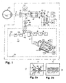
- Fig.1 shows the overall structure of the examination device, with a typical beam path of a slit lamp microscope for examining the front and rear eye portion of an eye.
- two parallel beam paths 10a lead to a 2-axis magnification changer 11. Both of the beams running in parallel have a focus set to infinity.
- the beam pair 10b which continues to run in parallel, reaches the front lens 12 of the microscope.
- the front lens 12 focuses the rays on the cornea of the subject 22.
- an ophthalmoscope lens 13 By an optional interposition of an ophthalmoscope lens 13 and a correspondingly optimized distance from the eye, the focal point lies on the fundus.
- a SDOCT 24 is coupled via a movable optical deflection unit 40 .
- the beam 3f of the SDOCT extends between the optical observation beam paths 10b to the object 22.
- the beam of the SDOCT can also be guided laterally offset over one of the observation beam paths 10b .
- the 3x magnification changer 11 has a second pair of beams rotated by 90 degrees. Via this second beam pair, an illumination and an observation beam of the SDO 23 are coupled in via two mirrors 18 and 19 .
- a lens combination 20a or 20b optionally inserted between mirror 18 or 19 and magnification changer (Galilean optics) 11 , the beams of the two optical systems 11 and 31 or 32 can be optimally adapted to each other.
- the two beams 17a and 17b are guided by the Galileiwechsler 11 , where depending on the rotational position of that different magnifications arise.
- the Galileiwechslers 11 In direct continuation of the Galileiwechslers 11 lead the parallel beam paths through the front lens 12 of the microscope and an alternately connected therebetween ophthalmoscope 13 to the object 22nd
- the SDO 23 has two optical paths 17a and 17b.
- the light of the light source 33 passes via an optical system 31 as a light beam 17a to the magnification changer 11 and on the previously described path to the object 22.
- the light component reflected by the object 22 passes on the second beam path via the magnification changer 11, which is optional Inserted lens combination 20b, the mirror 19, the lens combination 32 to the image sensor 34. With the swing stop 35 disturbing scattered lights are largely eliminated.
- the image information of the sensor 34 is supplied to an evaluation unit.
- the spectrometer 163 has a lens 164 which collimates the radiation 165 exiting the radiation guide 161 .
- the collimated radiation 167 is directed to a grating 169 .
- the grating 169 reflects each wavelength included in the radiation 167 impinging on a grating 169 in a different direction.
- This radiation 170 which is decomposed according to the wavelength components, is focused by means of a focusing lens 171 onto the camera line 159 having the camera pixels 157 . Each pixel 157 thus always receives only a very specific wavelength range.
- the positions of the various reflections in the object 22 along the propagation direction of the measurement beam 3g of the radiation source 1 can be determined.
- the reference arm 176 is connected to the coupler 160 via a monomode fiber 177a .
- the other end of the monomode fiber 177a is provided with an optional, e.g. B. piezoelectrically operating phase modulator 179 and this connected via a single-mode fiber 177 b with an optional polarization controller 180 .
- the radiation reaches a mirror 181, from which the radiation is again reflected back to the coupler 160 via the previously mentioned components.
- the radiation reflected back from the object 22 is superimposed with the radiation reflected by the reference arm 176 . Then go 50% of the radiation in the radiation conductor 161 from the fiber coupler 160th
- the SDOCT 24 contains the radiation source 1, the radiation attenuator 5 (optional), the polarization controller 7, the 2x2 monomode fiber coupler 160, the spectrometer 163, the fixation laser 2 (optional, the fixation Laser / pilot laser 2 is optional, because the radiation source 1 and in the near infrared possibly enough already visible to the patient), the reference arm 176, the polarization controller 18, the ferrule 57, the lens 183, the deflection unit 40, the drive unit 41 for the movable deflection unit 40, the lens combination 12 and 13 and the object 22.
- the constructed according to the Michelson principle interferometer can be both fiber optic and as geometric optics, ie without fibers but with a beam splitter cube instead of a 2x2 fiber coupler and a free jet instead of fibers built.
- the deflection unit 40 is movably provided as a translator. If a translator 40 is used together with a structure without fibers, even a 3-D scan can be achieved.
- a fundus image of the SDO is visible.
- a navigable brand is visible. This is either synthetic, superimposed by the software, the SDO image or with an additional LASER source, along the SDOCT beam path on the fundus imaged.
- a depth scan of an SDOCT is shown.
- the penetration depth is about 3mm.
- the length of the SDOCT B scan is determined inter alia by the deflection of the movable deflection unit 40 .
- At least 3 light sources are arranged in a plane around the front lens 12 of the slit lamp in a plane.
- the ring of these light sources is arranged concentrically to the measuring beam 3g of the SDOCT.
- the light sources can optionally be placed behind a diffuser.
- the light beams of the LEDs are reflected on the tear film of the examined eye 22 .
- the reflection on the tear film leads to the emergence of virtual images of the LEDs 200 within the eye.
- the locations of the virtual images of the LEDs are typically located a few millimeters behind the tear film, depending on the surface curvature of the tear film.
- the SDO maps the virtual images of the LEDs 200 to the image sensor 34 .
- Fig. 3 shows an embodiment with 8 LEDs, which are shown on the image sensor 34 . From the coordinates of the focal points> 201 of the LED images imaged on the image sensor 34 For example, a center 202 may be calculated. With the help of the light source 2 , the patient is instructed to look in a certain direction (fixation direction). Whether the patient is well fixed, z. B. be checked by the presence and the amplitude of the signals of the SDOCT are evaluated in the evaluation unit 173 . Possible structures that the SDOCT measures are the anterior surface of the cornea, the surface of the cornea, the anterior surface of the lens, the surface of the lens and the retina. Instead of an SDOCT, a time-domain OCT (TDOCT) can also be used.
- TDOCT time-domain OCT
- the image sensor 34 evaluates the pupil centroid 210 of the pupil 209 .
- the vector of the connecting line 211 between the pupil centroid 210 and the calculated center of the LEDs 202 is calculated.
- the length and direction of the connecting line 211 must be during the
- a photorefractive surgical intervention eg LASIK, LASEK, PRK
- Planning of a photorefractive surgical intervention are taken into account, because the corneal laser ablation pattern of today's conventional laser systems is centered on the pupillary centroid 210 . If, however, the visual axis does not pass through the center of gravity of the pupil 210 , as is often the case, then a certain error of the postoperative result is always accepted. Large distances between the center of the LEDs 202 and the pupil centroid 210 must be considered in the ablation to achieve a satisfactory postoperative refraction of the patient.
- the curvature of the anterior corneal surface can be measured by evaluating the distances of the LED centroids 201 mapped to the image sensor 34 with respect to one another. It is true that the radii of curvature increase with increasing distance between two LED centers 201 .
- the exact relationship between the radii of curvature and the LED centroids 201 is given by the position of the LEDs 200 disposed annularly on the slit lamp , the optics, and the geometry between the patient cornea and the image sensor 34. This relationship may be calculated and / or by means of a Method of calibration can be determined.
- the lens can be used to determine the radius of curvature of the flat and the radius of curvature of the steep meridian of the anterior corneal surface.
- the difference between the radii of curvature of the steep and flat meridians gives the astigmatism.
- the evaluation of the LED centroids on the image sensor 34 also yields the angle alpha between the horizontal axis of the image sensor 34 and the axis of the flat or steep meridian.
- the pattern of the iris imaged on the image sensor 34 is evaluated.
- the result of the evaluation of the iris pattern is to provide the angular position beta of a characteristic structure in the pattern of the iris with respect to the horizontal axis of the image sensor 34 .
- the angle gamma between the flat meridian (or the steep meridian) and the angular position of the characteristic iris structure can be calculated. It is assumed that the angle gamma for one and the same patient is firstly constant over time and secondly independent of the position of the patient (sitting or lying).
- This angle gamma must be known z. B. in photorefractive ablation z. B. by an excimer laser.
- Reason: Alpha can not be measured during the Excimerlaser anger because the excimer laser no necessary device z. B. in the form of LEDs 200 has.
- beta can be measured online by the excimer laser integrated eyetracker camera during the excimer laser treatment. Now, if beta is measured by the eye tracker camera and gamma is known, then the position of the flat or steep meridian alpha during the treatment can now be determined.
- the display unit 174 (see Fig. 1 ) is used to display the patient data, the positioning required for the positioning of the eye area to be measured, marks produced by software as a positioning aid and the measurement results.
- FIGS. 4a and 4b each show a brand created by software as a positioning aid.
- This can, for. B. a preferably displayed in the center of the eye area shown circle 175 whose diameter decreases with increasing signal strength of the detected by the evaluation unit 173 reflections of the SDOCTs.
- the color of the circle can change as soon as the signals are so high that they are considered reliable.
- the signals can also originate from a time-domain OCT.
- the diameter of the circle 175 may also be controlled based on the signal strength or sharpness of the image of the fundus or the anterior segment of the eye detected by the image sensor 34 .
- the diameter of the circle 175 can be regulated on the basis of the signal strength or sharpness of the LED images detected by the image sensor 34 .
- a control combination of the signal strengths or image sharpness of the SDOCT, the SDO observation field and the LED images detected by the SDO can also be selected.
- Fig. 4a shows a large circle 175, which means that the measurement signal is low. As a result, the user knows that he has to position the measuring device even better to the patient's eye.
- Fig. 4b shows a small circle 175.
- the measurement signal is strong and therefore reliable. The user knows that he can trigger the measurement because the signals are reliable.
Abstract
Description
Die Erfindung betrifft eine Untersuchungsvorrichtung zur Untersuchung eines Auges mit einer ersten Vorrichtung zur Erzeugung einer Abbildung des Auges, wobei die erste Vorrichtung ein Mikroskop sowie eine Beleuchtungseinheit zur Beleuchtung des Auges umfasst. Weiter betrifft die Erfindung ein Verfahren zur Untersuchung eines Auges mit einer Untersuchungsvorrichtung, wobei mit einer ersten Vorrichtung eine Abbildung des Auges erzeugt wird, indem das Auge mit einer Beleuchtungseinheit beleuchtet und mit einem Mikroskop die Abbildung erzeugt wird.The invention relates to an examination device for examining an eye with a first device for generating an image of the eye, wherein the first device comprises a microscope and a lighting unit for illuminating the eye. Furthermore, the invention relates to a method for examining an eye with an examination device, wherein with a first device, an image of the eye is generated by the eye illuminated with a lighting unit and the image is generated with a microscope.
Für die Beobachtung und Dokumentierung des Fundus werden verschiedene physikalische Verfahren angewandt. Bei der Fundusfotografie oder bei Untersuchungen mit einem SDO wird nur reflektiertes Licht von der Oberfläche des Fundus erfasst. Tiefer liegende Strukturen können durch die Verwendung von unterschiedlichen Wellenlängen der Beleuchtung oder konfokalen Optiken dargestellt werden. Der Arzt kann jedoch schon aufgrund der Bildinformation von der Oberfläche eine Vielzahl von Pathologien erkennen. Zusätzliche Informationen können der Topographie des Fundus entnommen werden. Dies wird beispielsweise bei der Verwendung eines Binokulartubus, welcher einen stereoskopischen Eindruck vermittelt, ermöglicht.Different physical methods are used to observe and document the fundus. In fundus photography or examinations with an SDO, only reflected light from the surface of the fundus is detected. Lower-lying structures can be represented by the use of different wavelengths of illumination or confocal optics. However, the doctor can already recognize a variety of pathologies due to the image information from the surface. Additional information can be found in the topography of the fundus. This is made possible, for example, when using a binocular tube which gives a stereoscopic impression.
Oft besteht jedoch das Bedürfnis, auch tiefer liegende Strukturen des Fundus darzustellen. Dies ist mit Untersuchungsgeräten möglich, welche beispielsweise die OCT-Technologie anwenden. Die neuere SDOCT-Technologie kann für diesen Zweck ebenfalls eingesetzt werden.Often, however, there is a need to represent deeper structures of the fundus. This is possible with examination devices which, for example, use OCT technology. The newer SDOCT technology can also be used for this purpose.
Sollen bei einem Patienten sowohl der Fundus als auch entsprechend tieferliegende Strukturen des Fundus untersucht werden, müssen hierfür verschiedene Untersuchungsgeräte benutzt werden. Entsprechend muss der Patient auch an verschiedenen Untersuchungsgeräten platziert werden. Dies ist sowohl kosten- als auch zeitintensiv und zudem für den Patienten unangenehm.If a patient is to examine both the fundus and correspondingly deeper structures of the fundus, different examination devices must be used for this purpose. Accordingly, the patient must also be placed on different examination devices. This is both costly and time consuming and also uncomfortable for the patient.
Aufgabe der Erfindung ist es, eine dem eingangs genannten technischen Gebiet zugehörende Vorrichtung zu schaffen, welche eine vereinfachte Untersuchung verschiedener Augenabschnitte, insbesondere des Fundus und der tieferliegenden Fundusstrukturen, ermöglicht.The object of the invention is to provide a device belonging to the technical field mentioned above, which allows a simplified examination of different eye sections, in particular the fundus and the underlying fundus structures.
Die Lösung der Aufgabe ist durch die Merkmale des Anspruchs 1 definiert. Eine Untersuchungsvorrichtung zur Untersuchung umfasst eine erste Vorrichtung zur Erzeugung einer Abbildung des Auges, wobei die erste Vorrichtung ein Mikroskop sowie eine Beleuchtungseinheit zur Beleuchtung des Auges umfasst. Gemäss der Erfindung umfasst die Untersuchungsvorrichtung eine zweite Vorrichtung zur Erzeugung einer Abbildung eines ersten Augenabschnittes sowie eine dritte Vorrichtung zur Erzeugung einer tiefenaufgelösten Abbildung eines zweiten Augenabschnittes. Mit der zweiten Vorrichtung ist die Abbildung des ersten Augenabschnitts mittels einer sequentiellen Abtastung des ersten Augenabschnitts mit einem Lichtstrahl erzeugbar und mit der dritten Vorrichtung ist eine Schnittansicht des zweiten Augenabschnittes parallel zu einer optischen Achse der Untersuchungsvorrichtung erzeugbar. Hierbei kann der zweite Augenabschnitt vom ersten Augenabschnitt verschieden sein. Vorzugsweise ist der zweite Augenabschnitt jedoch ein Teilbereich des ersten Augenabschnitts.The solution of the problem is defined by the features of claim 1. An examination device for examination comprises a first device for generating a Image of the eye, wherein the first device comprises a microscope and a lighting unit for illuminating the eye. According to the invention, the examination device comprises a second device for generating an image of a first eye section and a third device for generating a depth-resolved image of a second eye section. With the second device, the image of the first eye section can be generated by means of a sequential scanning of the first eye section with a light beam, and with the third device a sectional view of the second eye section can be generated parallel to an optical axis of the examination device. Here, the second eye portion may be different from the first eye portion. However, the second eye section is preferably a partial area of the first eye section.
Bei der ersten Vorrichtung handelt es sich insbesondere um ein sogenanntes Spaltlampenmikroskop mit einer entsprechenden, seitlichen Spaltbeleuchtung, mit welcher ein schmales, spaltförmiges Lichtbündel erzeugbar ist.In particular, the first device is a so-called slit lamp microscope with a corresponding, lateral slit illumination, with which a narrow, slit-shaped light beam can be generated.
Die zweite Vorrichtung ist insbesondere ein sogenanntes SDO (scanning digital ophthalmoscope) und die dritte Vorrichtung ist insbesondere ein OCT (optical coherence tomograph), d. h. eine Vorrichtung zur Durchführung einer optischen Kohärenztomographie. Vorzugsweise handelt es sich hierbei um die moderne spektrale optische Kohärenztomographie (SDOCT - spectral domain optical coherence tomography). Das Kombinieren eines SDO's mit einer Spaltlampe bringt allein schon den Vorteil, dass die scannende, reflexarme Beleuchtung, zusammen mit der Beobachtung durch den Binokulartubus, einen guten stereoskopischen Eindruck des Fundus ermöglicht.The second device is in particular a so-called SDO (scanning digital ophthalmoscope) and the third device is in particular an OCT (optical coherence tomograph), d. H. an apparatus for performing an optical coherence tomography. This is preferably modern spectral optical coherence tomography (SDOCT - spectral domain optical coherence tomography). Combining an SDO with a slit lamp alone has the advantage that the scanning, low-reflection illumination, together with the observation through the binocular tube, allows a good stereoscopic impression of the fundus.
Die gemeinsame Verwendung des SDOs und eines SDOCTs erlaubt eine erweiterte Untersuchungsmöglichkeit, welche auf dem gleichen Untersuchungsgerät durchgeführt werden kann. Das SDO liefert dem Untersucher erste wichtige Informationen zu möglichen Pathologien auf der Netzhaut. Das SDOCT erlaubt nun das Scannen von interessierenden Stellen auf dem Fundus, ohne dass der Patient dafür an ein anderes Untersuchungsgerät umplatziert werden muss. Der zu scannende Bereich wird mit einer auf dem Fundus projizierten Linie sichtbar gemacht. Mit der Umlenkeinheit 40 wird die Position bestimmt. Als Lichtquelle für die Fixationshilfe des Patienten dient vorzugsweise eine sichtbare Laserquelle 2, welche über den 2x2 Koppler 162 in die Faser 14b und damit auf dem gleichen Strahlengang wie der Messstrahl des SDOCT auf den zu untersuchenden Bereich gelangt. Fixationslaser 2 und Messlaser 1 sind somit immer kongruent. Der Zielbereich des Messlasers könnte in einer alternativen Lösung auch synthetisch, abhängig von der Position des Translators durch die Software berechnet, dem SDO-Bild überlagert werden.The joint use of the SDO and an SDOCT allows an extended examination possibility, which can be carried out on the same examination device. The SDO provides the examiner with first important information on possible pathologies on the retina. The SDOCT now allows the scanning of sites of interest on the fundus without the patient having to be relocated to another examination device. The area to be scanned is visualized with a line projected on the fundus. With the deflection unit 40 , the position is determined. The light source for the fixation aid of the patient is preferably a visible one
B-Scans sind auch für den vorderen Augenabschnitt, insbesondere im Bereich der hinteren Augenkammer und der Ziliarkörper, interessant (Kammerwinkel). Für Untersuchungen im vorderen Bereich des Auges darf die Ophthalmoskopierlinse 13 nicht zwischengeschaltet werden.B-scans are also interesting for the anterior segment of the eye, especially in the area of the posterior chamber of the eye and the ciliary body (chamber angle). For examinations in the anterior region of the eye, the ophthalmoscope lens 13 must not be interposed.
Die zur Erläuterung des Ausführungsbeispiels verwendeten Zeichnungen zeigen:
- Fig. 1
- eine schematisch dargestellte Untersuchungsvorrichtung gemäss der Erfindung;
- Fig. 2a
- eine schematische Abbildung eines Augenfundus mit einer Markierung;
- Fig. 2b
- eine schematische Abbildung eines zweidimensionalen Tiefenscans der in
Figur 2a markierten Region der Fundusabbildung ausFig. 2a ; - Fig. 3
- eine Ausführungsform der erfindungsgemässen Untersuchungsvorrichtung mit 8 LEDs zur Messung des Abstands zwischen der Sehachse und dem Pupillenschwerpunkt;
- Fig. 4a
- einen softwaremässig erzeugten Kreis mit grossem Durchmesser als Positionierhilfe bei einem schwachen Messsignal und
- Fig.4b
- einen softwaremässig erzeugten Kreis mit kleinem Durchmesser als Positionierhilfe bei einem starken Messsignal.
- Fig. 1
- a schematically illustrated examination device according to the invention;
- Fig. 2a
- a schematic illustration of an eye fundus with a marker;
- Fig. 2b
- a schematic illustration of a two-dimensional depth scan of in
FIG. 2a marked region of fundus imageFig. 2a ; - Fig. 3
- an embodiment of the inventive examination device with 8 LEDs for measuring the distance between the visual axis and the pupillary center of gravity;
- Fig. 4a
- a software generated circle with a large diameter as a positioning aid with a weak measurement signal and
- 4b
- a software generated circle with a small diameter as a positioning aid with a strong measurement signal.
Grundsätzlich sind in den Figuren gleiche Teile mit gleichen Bezugszeichen versehen.Basically, the same parts are provided with the same reference numerals in the figures.
Das SDO 23 verfügt über zwei Strahlengänge 17a und 17b. Das Licht der Lichtquelle 33 gelangt über eine Optik 31 als Lichtbündel 17a zum Vergrösserungswechsler 11 und auf bereits beschriebenem Weg zum Objekt 22. Der vom Objekt 22 reflektierte Lichtanteil gelangt auf dem zweiten Strahlengang via den Vergrösserungswechsler 11, der optional eingesetzten Linsenkombination 20b, den Spiegel 19, die Linsenkombination 32 zum Bildsensor 34. Mit der Schwingblende 35 werden störende Streulichter weitgehend eliminiert. Die Bildinformation des Sensors 34 wird einer Auswerteeinheit zugeführt.The SDO 23 has two optical paths 17a and 17b. The light of the light source 33 passes via an optical system 31 as a light beam 17a to the magnification changer 11 and on the previously described path to the
Das Spektrometer 163 hat eine Linse 164, welche die aus dem Strahlungsleiter 161 austretende Strahlung 165 kollimiert. Die kollimierte Strahlung 167 wird auf ein Gitter 169 geführt. Das Gitter 169 reflektiert jede Wellenlänge, die in der auf ein Gitter 169 auftreffenden Strahlung 167 enthalten ist, in eine andere Richtung. Diese nach den Wellenlängenanteilen zerlegte Strahlung 170 wird mittels einer Fokussierlinse 171 auf die die Kamerapixel 157 aufweisende Kamerazeile 159 fokussiert. Jedes Pixel 157 empfängt somit immer nur einen ganz bestimmten Wellenlängenbereich. Mit der Ermittlung der Intensitäten der von den Kamerapixeln detektierten Wellenlängenbereiche und mit Hilfe einer mathematischen Umformung (Fouriertransformation) in einer Auswerteeinheit 173 können die Positionen der verschiedenen Reflexionen im Gegenstand 22 entlang der Ausbreitungsrichtung des Messstrahls 3g der Strahlungsquelle 1 ermittelt werden.The spectrometer 163 has a
Der Referenzarm 176 ist über eine Monomodefaser 177a mit dem Koppler 160 verbunden. Das andere Ende der Monomodefaser 177a ist mit einem optionalen, z. B. piezoelektrisch arbeitenden Phasenmodulator 179 und dieser über eine Monomodefaser 177b mit einem optionalen Polarisationskontroller 180 verbunden. Ausgehend von dem Polarisationskontroller 180 gelangt die Strahlung auf einen Spiegel 181, von dem die Strahlung wieder über die vorgängig angeführten Komponenten zum Koppler 160 zurück reflektiert wird.The
Im Faserkoppler 160 wird die vom Gegenstand 22 rückreflektierte Strahlung mit der vom Referenzarm 176 reflektierten Strahlung überlagert. Vom Faserkoppler 160 gehen dann 50 % der Strahlung in den Strahlungsleiter 161. In the fiber coupler 160 , the radiation reflected back from the
Der SDOCT 24 enthält die Strahlungsquelle 1, den Strahlungsabschwächer 5 (optional), den Polarisationskontroller 7, den 2x2 Monomodefaserkoppler 160, das Spektrometer 163, den Fixationslaser 2 (optional, der Fixationslaser/Pilotlaser 2 ist optional, weil die Strahlungsquelle 1 auch im nahen Infrarotbereich unter Umständen schon genügend sichtbar ist für den Patienten), den Referenzarm 176, den Polarisationskontroller 18, die Ferrule 57, die Linse 183, die Umlenkeinheit 40, die Ansteuereinheit 41 für die bewegliche Umlenkeinheit 40, die Linsenkombination 12 und 13 und den Gegenstand 22. The
Das nach dem Michelson-Prinzip aufgebaute Interferometer kann sowohl faseroptisch als auch als geometrische Optik, d. h. ohne Fasern aber mit einem Strahlenteilerwürfel anstelle eines 2x2 Faserkopplers und einem Freistrahl statt Fasern, aufgebaut werden. Bei der Verwendung von Fasern und der Forderung eines B-Scans ist die Umlenkeinheit 40 beweglich als Translator vorgesehen. Wird ein Translator 40 zusammen mit einem Aufbau ohne Fasern verwendet, kann gar ein 3-D Scan erzielt werden.The constructed according to the Michelson principle interferometer can be both fiber optic and as geometric optics, ie without fibers but with a beam splitter cube instead of a 2x2 fiber coupler and a free jet instead of fibers built. With the use of fibers and the requirement of a B-scan, the deflection unit 40 is movably provided as a translator. If a translator 40 is used together with a structure without fibers, even a 3-D scan can be achieved.
In
In
Nochmals zurück zu
Planung eines photorefraktiven chirurgischen Eingriffs (z. B. LASIK, LASEK, PRK) berücksichtigt werden, weil das korneale Laserablationsmuster der heute üblichen Lasersysteme auf den Pupillenschwerpunkt 210 zentriert wird. Falls aber die Sehachse nicht durch den Pupillenschwerpunkt 210 geht, was oft der Fall ist, wird dadurch immer ein gewisser Fehler des postoperativen Ergebnisses in Kauf genommen. Grosse Abstände zwischen dem Zentrum der LEDs 202 und dem Pupillenschwerpunkt 210 müssen bei der Ablation berücksichtigt werden, um eine zufriedenstellende postoperative Refraktion des Patienten zu erzielen.Planning of a photorefractive surgical intervention (eg LASIK, LASEK, PRK) are taken into account, because the corneal laser ablation pattern of today's conventional laser systems is centered on the
Mit Hilfe der acht LEDs 200 (Bedingung: Es müssen mindestens 5 LEDs sein) kann die Krümmung der Hornhautvorderfläche gemessen werden, indem die auf den Bildsensor 34 abgebildeten Abstände der LED-Schwerpunkte 201 zueinander ausgewertet werden. Dabei gilt, dass die Krümmungsradien mit zunehmendem Abstand zweier LED-Schwerpunkte 201 zunehmen. Die genaue Beziehung zwischen den Krümmungsradien und den LED-Schwerpunkten 201 ist gegeben durch die Position der ringförmig an der Spaltlampe angeordneten LEDs 200, der Optik und der Geometrie zwischen der Patientenhornhaut und dem Bildsensor 34. Diese Beziehung kann rechnerisch und/oder mit Hilfe einer Katibrationsmethode ermittelt werden. Insbesondere kann damit der Krümmungsradius des flachen und der Krümmungsradius des steilen Meridians der Hornhautvorderfläche bestimmt werden. Die Differenz zwischen den Krümmungsradien des steilen und flachen Meridians ergibt den Astigmatismus. Die Auswertung der LED-Schwerpunkte auf dem Bildsensor 34 ergibt auch den Winkel Alpha zwischen der horizontalen Achse des Bildsensors 34 und der Achse des flachen oder des steilen Meridians.With the aid of the eight LEDs 200 (condition: there must be at least 5 LEDs), the curvature of the anterior corneal surface can be measured by evaluating the distances of the
Zusätzlich zu den LED-Schwerpunkten 201 wird das auf dem Bildsensor 34 abgebildete Muster der Iris ausgewertet. Die Auswertung des Irismusters soll als Ergebnis die Winkellage Beta einer charakteristischen Struktur im Muster der Iris bezüglich der horizontalen Achse des Bildsensors 34 liefern. Damit kann nun durch einfache Subtraktion (Alpha - Beta) der Winkel Gamma zwischen dem flachen Meridian (oder dem steilen Meridian) und der Winkellage der charakteristischen Irisstruktur berechnet werden. Es wird angenommen, dass der Winkel Gamma für ein und denselben Patienten erstens zeitlich konstant ist und zweitens unabhängig von der Position des Patienten (sitzend oder liegend) ist.In addition to the
Dieser Winkel Gamma muss bekannt sein z. B. bei der photorefraktiven Ablation z. B. durch einen Excimerlaser. Begründung: Alpha kann während der Excimerlaserbehandlung nicht gemessen werden, weil der Excimerlaser keine dazu notwendige Vorrichtung z. B. in Form von LEDs 200 hat. Beta kann z.B. von der im Excimerlaser integrierten Eyetracker-Kamera online während der Excimerlaserbehandlung gemessen werden. Wird jetzt Beta von der Eyetracker-Kamera gemessen und ist Gamma bekannt, so kann nun auch die Lage des flachen oder steilen Meridians Alpha während der Behandlung ermittelt werden. Weil Alpha in der liegenden Position des Patienten bei der Excimerlaserbehandlung nicht immer identisch ist mit der Winkellage Alpha während der vorgängigen Messung in sitzender Position, ist es bei der ablativen Korrektur eines Astigmatismus durch einen Laser nötig, Gamma zu kennen, ansonsten der Astigmatismus vom Laser falsch korrigiert wird.This angle gamma must be known z. B. in photorefractive ablation z. B. by an excimer laser. Reason: Alpha can not be measured during the Excimerlaserbehandlung because the excimer laser no necessary device z. B. in the form of
Die Anzeigeeinheit 174 (siehe
Claims (17)
Priority Applications (1)
| Application Number | Priority Date | Filing Date | Title |
|---|---|---|---|
| EP07405084A EP1969995A1 (en) | 2007-03-14 | 2007-03-14 | Eye testing device |
Applications Claiming Priority (1)
| Application Number | Priority Date | Filing Date | Title |
|---|---|---|---|
| EP07405084A EP1969995A1 (en) | 2007-03-14 | 2007-03-14 | Eye testing device |
Publications (1)
| Publication Number | Publication Date |
|---|---|
| EP1969995A1 true EP1969995A1 (en) | 2008-09-17 |
Family
ID=38255511
Family Applications (1)
| Application Number | Title | Priority Date | Filing Date |
|---|---|---|---|
| EP07405084A Pending EP1969995A1 (en) | 2007-03-14 | 2007-03-14 | Eye testing device |
Country Status (1)
| Country | Link |
|---|---|
| EP (1) | EP1969995A1 (en) |
Cited By (2)
| Publication number | Priority date | Publication date | Assignee | Title |
|---|---|---|---|---|
| DE202009002387U1 (en) | 2008-12-22 | 2010-05-12 | Maiorova, Tatiana, Dmitrov | Optical arrangement for changing an imaging ratio or a refractive power |
| DE102008064512A1 (en) | 2008-12-22 | 2010-06-24 | Maiorova, Tatiana, Dmitrov | Optical arrangement for use in e.g. camera-phone for changing imaging condition and/or optical refraction power, has optical elements, where change of direction and/or vergrence is taken place in optical light path between elements |
Citations (11)
| Publication number | Priority date | Publication date | Assignee | Title |
|---|---|---|---|---|
| US5009498A (en) * | 1990-03-20 | 1991-04-23 | Computed Anatomy Inc. | Interchangeable keratoscope device |
| US5418582A (en) * | 1993-10-15 | 1995-05-23 | Lions Eye Institute Perth | Photokeratoscope apparatus and method |
| US5975697A (en) * | 1998-11-25 | 1999-11-02 | Oti Ophthalmic Technologies, Inc. | Optical mapping apparatus with adjustable depth resolution |
| EP1231496A2 (en) * | 1994-08-18 | 2002-08-14 | Carl Zeiss | Optical coherence tomography assisted surgical apparatus |
| WO2004113958A2 (en) * | 2003-06-16 | 2004-12-29 | Visx, Incorporated | Methods and devices for registering optical measurement datasets of an optical system |
| US20050140984A1 (en) * | 2003-12-31 | 2005-06-30 | Hitzenberger Christoph K. | Efficient optical coherence tomography (OCT) system and method for rapid imaging in three dimensions |
| US20050174537A1 (en) * | 2003-10-24 | 2005-08-11 | Nevyas Herbert J. | Ophthalmic operative keratometer with movable fixation/centration device |
| WO2006058735A1 (en) * | 2004-12-02 | 2006-06-08 | Carl Zeiss Meditec Ag | Enhanced optical coherence tomography for anatomical mapping |
| US20060158655A1 (en) * | 2005-01-20 | 2006-07-20 | Everett Matthew J | Apparatus and method for combined optical-coherence-tomographic and confocal detection |
| US20060176448A1 (en) * | 1999-11-01 | 2006-08-10 | Van De Velde Frans J | Relaxed confocal catadioptric scanning laser ophthalmoscope |
| GB2429522A (en) * | 2005-08-26 | 2007-02-28 | Univ Kent Canterbury | Optical mapping apparatus |
-
2007
- 2007-03-14 EP EP07405084A patent/EP1969995A1/en active Pending
Patent Citations (11)
| Publication number | Priority date | Publication date | Assignee | Title |
|---|---|---|---|---|
| US5009498A (en) * | 1990-03-20 | 1991-04-23 | Computed Anatomy Inc. | Interchangeable keratoscope device |
| US5418582A (en) * | 1993-10-15 | 1995-05-23 | Lions Eye Institute Perth | Photokeratoscope apparatus and method |
| EP1231496A2 (en) * | 1994-08-18 | 2002-08-14 | Carl Zeiss | Optical coherence tomography assisted surgical apparatus |
| US5975697A (en) * | 1998-11-25 | 1999-11-02 | Oti Ophthalmic Technologies, Inc. | Optical mapping apparatus with adjustable depth resolution |
| US20060176448A1 (en) * | 1999-11-01 | 2006-08-10 | Van De Velde Frans J | Relaxed confocal catadioptric scanning laser ophthalmoscope |
| WO2004113958A2 (en) * | 2003-06-16 | 2004-12-29 | Visx, Incorporated | Methods and devices for registering optical measurement datasets of an optical system |
| US20050174537A1 (en) * | 2003-10-24 | 2005-08-11 | Nevyas Herbert J. | Ophthalmic operative keratometer with movable fixation/centration device |
| US20050140984A1 (en) * | 2003-12-31 | 2005-06-30 | Hitzenberger Christoph K. | Efficient optical coherence tomography (OCT) system and method for rapid imaging in three dimensions |
| WO2006058735A1 (en) * | 2004-12-02 | 2006-06-08 | Carl Zeiss Meditec Ag | Enhanced optical coherence tomography for anatomical mapping |
| US20060158655A1 (en) * | 2005-01-20 | 2006-07-20 | Everett Matthew J | Apparatus and method for combined optical-coherence-tomographic and confocal detection |
| GB2429522A (en) * | 2005-08-26 | 2007-02-28 | Univ Kent Canterbury | Optical mapping apparatus |
Non-Patent Citations (1)
| Title |
|---|
| SHULIANG JIAO ET AL: "Simultaneous acquisition of sectional and fundus ophthalmic images with spectral-domain optical coherence tomography", 24 January 2005, OPTICS EXPRESS, OPTICAL SOCIETY OF AMERICA, WASHINGTON, DC,, US, PAGE(S) 444-452, ISSN: 1094-4087, XP002370566 * |
Cited By (4)
| Publication number | Priority date | Publication date | Assignee | Title |
|---|---|---|---|---|
| DE202009002387U1 (en) | 2008-12-22 | 2010-05-12 | Maiorova, Tatiana, Dmitrov | Optical arrangement for changing an imaging ratio or a refractive power |
| DE102008064512A1 (en) | 2008-12-22 | 2010-06-24 | Maiorova, Tatiana, Dmitrov | Optical arrangement for use in e.g. camera-phone for changing imaging condition and/or optical refraction power, has optical elements, where change of direction and/or vergrence is taken place in optical light path between elements |
| WO2010072218A1 (en) | 2008-12-22 | 2010-07-01 | Future Optics Gbr | Optical system for changing an image scale or a refractive power |
| US8615143B2 (en) | 2008-12-22 | 2013-12-24 | Future Optics Gbr | Optical arrangement for varying an imaging ratio or of a refractive power |
Similar Documents
| Publication | Publication Date | Title |
|---|---|---|
| EP1494575B1 (en) | Measurement of optical properties | |
| EP2445387B1 (en) | Fixation control device and method for controlling the fixation of an eye | |
| EP2799002B1 (en) | Method and analysis system for performing ophthalmic examinations | |
| DE102016001659B4 (en) | Eye surgery microscope and eye surgery accessory | |
| WO2018083323A1 (en) | A method for self-examination of an eye and ophthalmological self-examination apparatus | |
| WO2016041640A1 (en) | System for optical coherence tomography, comprising a zoomable kepler system | |
| WO2010031540A2 (en) | Measuring system for ophthalmic surgery | |
| DE112017000663T5 (en) | Ophthalmological device and ophthalmological examination system | |
| DE112017000673T5 (en) | Ophthalmological device and ophthalmological examination system | |
| DE102014010350A1 (en) | Eye surgery system | |
| WO2012084170A9 (en) | Device for interferometrically measuring the eye length and the anterior eye segment | |
| EP3585245B1 (en) | Method and arrangement for high-resolution topography of the cornea of an eye | |
| JP7368581B2 (en) | Ophthalmology equipment and ophthalmology information processing equipment | |
| DE102007047460A1 (en) | Apparatus and method for examining the ocular fundus, in particular the photoreceptors | |
| EP0563454A1 (en) | Method and apparatus for investigating the eyes | |
| WO2017191128A1 (en) | Ophthalmological length measurement by means of dual-beam space-time domain wavelength tuning low-coherence interferometry | |
| EP1624795A2 (en) | Method and arrangement for measuring the front section of the eye | |
| DE102007027683A1 (en) | Apparatus and method for determining anterior chamber depth and eye length of an eye | |
| EP1969995A1 (en) | Eye testing device | |
| JP2021191552A (en) | Ophthalmologic inspection device | |
| JP2018114230A (en) | Ophthalmologic apparatus | |
| EP2621330B1 (en) | Method and device for determining various biometric parameters of an eye by interferometry | |
| JP2020195883A (en) | Ophthalmologic inspection device | |
| DE102012011880A1 (en) | Contactless measuring device for ophthalmic calculation and selection of intraocular lenses, has keratometer arrangement that is provided for determining corneal curvature of eye | |
| EP4321084A1 (en) | System for recording and visualizing oct signals |
Legal Events
| Date | Code | Title | Description |
|---|---|---|---|
| PUAI | Public reference made under article 153(3) epc to a published international application that has entered the european phase |
Free format text: ORIGINAL CODE: 0009012 |
|
| AK | Designated contracting states |
Kind code of ref document: A1 Designated state(s): AT BE BG CH CY CZ DE DK EE ES FI FR GB GR HU IE IS IT LI LT LU LV MC MT NL PL PT RO SE SI SK TR |
|
| AX | Request for extension of the european patent |
Extension state: AL BA HR MK RS |
|
| AKX | Designation fees paid | ||
| REG | Reference to a national code |
Ref country code: DE Ref legal event code: 8566 |
|
| STAA | Information on the status of an ep patent application or granted ep patent |
Free format text: STATUS: THE APPLICATION IS DEEMED TO BE WITHDRAWN |