EP1969975A1 - Device for transporting a child - Google Patents
Device for transporting a child Download PDFInfo
- Publication number
- EP1969975A1 EP1969975A1 EP07104249A EP07104249A EP1969975A1 EP 1969975 A1 EP1969975 A1 EP 1969975A1 EP 07104249 A EP07104249 A EP 07104249A EP 07104249 A EP07104249 A EP 07104249A EP 1969975 A1 EP1969975 A1 EP 1969975A1
- Authority
- EP
- European Patent Office
- Prior art keywords
- brace
- accordance
- enclosure
- enclosures
- hinge
- Prior art date
- Legal status (The legal status is an assumption and is not a legal conclusion. Google has not performed a legal analysis and makes no representation as to the accuracy of the status listed.)
- Withdrawn
Links
Images

Classifications
-
- B—PERFORMING OPERATIONS; TRANSPORTING
- B60—VEHICLES IN GENERAL
- B60N—SEATS SPECIALLY ADAPTED FOR VEHICLES; VEHICLE PASSENGER ACCOMMODATION NOT OTHERWISE PROVIDED FOR
- B60N2/00—Seats specially adapted for vehicles; Arrangement or mounting of seats in vehicles
- B60N2/24—Seats specially adapted for vehicles; Arrangement or mounting of seats in vehicles for particular purposes or particular vehicles
- B60N2/26—Seats specially adapted for vehicles; Arrangement or mounting of seats in vehicles for particular purposes or particular vehicles for children
- B60N2/28—Seats readily mountable on, and dismountable from, existing seats or other parts of the vehicle
- B60N2/2875—Seats readily mountable on, and dismountable from, existing seats or other parts of the vehicle inclinable, as a whole or partially
-
- B—PERFORMING OPERATIONS; TRANSPORTING
- B60—VEHICLES IN GENERAL
- B60N—SEATS SPECIALLY ADAPTED FOR VEHICLES; VEHICLE PASSENGER ACCOMMODATION NOT OTHERWISE PROVIDED FOR
- B60N2/00—Seats specially adapted for vehicles; Arrangement or mounting of seats in vehicles
- B60N2/24—Seats specially adapted for vehicles; Arrangement or mounting of seats in vehicles for particular purposes or particular vehicles
- B60N2/26—Seats specially adapted for vehicles; Arrangement or mounting of seats in vehicles for particular purposes or particular vehicles for children
- B60N2/28—Seats readily mountable on, and dismountable from, existing seats or other parts of the vehicle
- B60N2/2821—Seats readily mountable on, and dismountable from, existing seats or other parts of the vehicle having a seat and a base part
-
- B—PERFORMING OPERATIONS; TRANSPORTING
- B60—VEHICLES IN GENERAL
- B60N—SEATS SPECIALLY ADAPTED FOR VEHICLES; VEHICLE PASSENGER ACCOMMODATION NOT OTHERWISE PROVIDED FOR
- B60N2/00—Seats specially adapted for vehicles; Arrangement or mounting of seats in vehicles
- B60N2/24—Seats specially adapted for vehicles; Arrangement or mounting of seats in vehicles for particular purposes or particular vehicles
- B60N2/26—Seats specially adapted for vehicles; Arrangement or mounting of seats in vehicles for particular purposes or particular vehicles for children
- B60N2/28—Seats readily mountable on, and dismountable from, existing seats or other parts of the vehicle
- B60N2/2842—Seats readily mountable on, and dismountable from, existing seats or other parts of the vehicle adapted to carry the child, when dismounted from the vehicle
- B60N2/2845—Seats readily mountable on, and dismountable from, existing seats or other parts of the vehicle adapted to carry the child, when dismounted from the vehicle having handles
-
- B—PERFORMING OPERATIONS; TRANSPORTING
- B60—VEHICLES IN GENERAL
- B60N—SEATS SPECIALLY ADAPTED FOR VEHICLES; VEHICLE PASSENGER ACCOMMODATION NOT OTHERWISE PROVIDED FOR
- B60N2/00—Seats specially adapted for vehicles; Arrangement or mounting of seats in vehicles
- B60N2/24—Seats specially adapted for vehicles; Arrangement or mounting of seats in vehicles for particular purposes or particular vehicles
- B60N2/26—Seats specially adapted for vehicles; Arrangement or mounting of seats in vehicles for particular purposes or particular vehicles for children
- B60N2/28—Seats readily mountable on, and dismountable from, existing seats or other parts of the vehicle
- B60N2/2857—Seats readily mountable on, and dismountable from, existing seats or other parts of the vehicle characterised by the peculiar orientation of the child
- B60N2/2863—Seats readily mountable on, and dismountable from, existing seats or other parts of the vehicle characterised by the peculiar orientation of the child backward facing
Definitions
- the invention concerns a device for transporting a child in accordance with the preamble of claim 1.
- a device is known inter alia from EP 1481616 .
- the known device has a U-shaped carrier that is placed under both enclosures. This device is large, heavy and not easy to handle.
- the device is in accordance with the characterizing part of claim 1. In this way there is no need for further parts than the enclosures and the supporting brace for carrying a child in a safe way. As the brace supports the enclosures sideways the forces acting between the child and the transporting device are directly transferred to or from the brace and the bottoms so that side walls need not take a sideways directed load and can be very light. This makes the device easy to carry.
- the device is in accordance with claim 2. This makes it easy to change the position of the enclosures from sitting position to lying position. When the brace is moved relative to the other enclosure this movement lets the enclosures rotate around the first hinge and makes them change from the sitting position to the lying position and vice versa.
- the device is in accordance with claim 3.
- the brace is fastened more stable to the side walls.
- the device is in accordance with claim 4.
- the brace has the shape of an uninterrupted hoop which can be relatively light.
- the device is in accordance with claim 5.
- the turning points of the second hinge have a certain distance from each other which makes the second hinge more stable.
- the device is in accordance with claim 6.
- it is easy to position the brace and the enclosures in two stable positions. In this way, the user can bring the inner child seat easily from a lying position to a sitting position or vice versa.
- the device is in accordance with claim 7. This way the device can be made very light while the child is adequately cushioned in the enclosures.
- the device is in accordance with claim 8. This way the enclosures together form a smooth part that does not need fasteners for connecting the various parts.
- the device is in accordance with claim 9. This way the enclosures can rest directly on a table or a floor.
- the device is in accordance with claim 10. This makes the enclosures very light and easy to produce.
- the device is in accordance with claim 11. As a result it is possible to bring the device from a sitting position to a lying position or vice versa whereby there is no need to change the length of the shoulder straps as they are automatically re-adjusted due to the movement of the brace relative to the upper enclosure.
- the device is in accordance with claim 12. In this way the position of the straps in the upper enclosure can be adjusted in an easy way to the length of the child.
- the device is in accordance with claim 13.
- the carrying handle is coupled to the strongest part of the device that supports both enclosures and when the carrying handle is positioned near the brace the enclosures can be moved from sitting position to laying position and vice versa without obstruction by the carrying handle.
- the device is in accordance with claim 14.
- the carrying handle is shorter than half the length of the device the carrying handle is very low above the child. This makes carrying the transporting device and placing the device in a car easier.
- the device is in accordance with claim 15.
- the outer shell gives additional protection to and strengthens the enclosures so that the child in the enclosures is better protected and the enclosures can be kept very light. Also it makes it easy to place the enclosures with the child positioned in the straps in the car.
- the device is in accordance with claim 16. This makes coupling the enclosures to the outer shell easier as only the brace has to be coupled.
- the device is in accordance with claim 17.
- the brace is coupled to the outer shell in an easy way and can be uncoupled at the side of the lower enclosure and/or at the side of the upper enclosure.
- the device is in accordance with claim 18.
- enclosures with the child in it can be placed in an easy movement on a transport or support means.
- the device is in accordance with claim 19.
- the device can be carried with the sling around a shoulder which makes the carrying of it easy.
- the invention also concerns the clothing for the device in accordance with claim 20.
- the clothing with side covers no material or parts of the child can come between the upper enclosure and the lower enclosure in the opening thereby preventing damage or accidents.
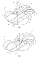
- Figure 1 and 2 show a child seat also known as an infant carrier, hereafter referred to as an inner child seat.
- the inner child seat is designed as being suitable for new born children and/or very young children.
- Figure 1 shows the inner child seat in a first position whereby the inner child seat is positioned such that there is an angle between the child's' legs and its back so that the child more or less sits in the inner child seat.
- Figure 2 shows the inner child seat in a second position whereby the inner child seat is positioned such that the child can lay extended with its legs and back more or less in a flat plane or slightly angled under an angle of 10 - 15 degrees.
- the inner child seat has a lower body enclosure 2 and an upper body enclosure 6 which are connected in the bottom plane by a hinge 13.
- the lower body enclosure 2 is more or less U-shaped with lower side supports 3 which extend above the plane of a leg support 1.
- the upper body enclosure 6 also is more or less U-shaped with upper side supports 4 extending above the plane of a back support 8.
- the back support 8 is considerably longer than the leg support 1 as the young child's back is longer than its legs.
- the hinge 13 connects the leg support 1 and the back support 8.
- the side supports 4 on the top side away from the lower body enclosure 2 function as head supports 7 for sideways supporting the head of the child, which is slightly smaller than its body so that the distance between the head supports 7 is smaller than the distance between the upper side supports 4. For further protecting the head of the child there are head cushions 5.
- the outside of the upper body enclosure 6 is formed by an upper outer wall 10, the outside of the lower body enclosure 2 is formed by the lower outer wall 17.
- the upper outer wall 10 is supported by two upper feet 12 and the lower outer wall 17 is supported by two lower feet 14.
- the lower feet 14 and the upper feet 12 can be positioned on a flat surface and then form an arc so that the inner child seat can rock on this surface.
- the leg support 1 and back support 8, which are coupled with the hinge 13 are more or less perpendicular to each other so that the child can sit in the inner child seat.
- the lower side supports 3, the upper side supports 4 and the head supports 7 are sideways supported by a brace 15.
- the brace 15 is hingeably connected to the lower body enclosure 2 and movably connected to the upper body enclosure 6. In the first position, shown in figure 1 , the brace 15 is in a high position latched to the upper body enclosure 6. In the second position shown in figure 2 the brace 15 has moved downwards along the upper body enclosure 6. In this position the lower body enclosure 2 and the upper body enclosure 6 have moved relative to one another by rotating in the hinge 13 and the leg support 1 and the back support 8 are more or less in line. It is possible that the brace 15 is latched in the lower position on the upper body enclosure 6 or that it can be latched into one or more intermediate positions.
- the inner child seat is shown ready for use and is covered in the customary manner with padded clothing in order to improve comfort of the child as much as possible.
- the padded clothing is provided with a cover pad 16 that covers the gap between the lower body enclosure 2 and the upper body enclosure 6 in the situation that the inner child seat is in the second position in order to prevent that the child's limbs being trapped in the gap between the enclosures.
- Figures 3 and 4 show the inner child seat in respectively first and second position as shown in figures 1 and 2 without the padded clothing.
- the brace 15 is provided with a pin 21 that slides in a slot 20 that is in the upper side support 4 so that the brace 15 is guided along the side wall of the upper side support 4.
- the position of the brace 15 can be fixed by locking the pin 21 in the end positions of the slot 20.
- the brace 15 is further provided with a carrying handle 9 that is rotatable coupled to the brace 15 by a handle hinge 11.
- the handle hinge 11 has a handle release knob 18 so that the carrying handle 9 can be positioned along the brace 15 and more or less perpendicular to the brace 15 as indicated with interrupted lines in figure 3 whereby the inner child seat can be carried using the carrying handle 9.
- the handle hinge 11 is connected to the brace 15 at a distance approximately one third of the length of the inner child seat from the upper or head side of the upper body enclosure 6 so that the carrying handle 9 is considerably shorter than half the length of the inner child seat.
- a grip 19 in the middle of the carrying handle 9 is, because of the short carrying handle 9, relative low above the center of gravity of the inner child seat.
- This short carrying handle 9 makes it easier to carry the inner child seat close to the body and to position the inner child seat in a limited space such as the rear seat of a car.
- the brace 15 is provided on both sides of the inner child seat with a cavity 22.
- the lower body enclosure 2 and the upper body enclosure 6 as shown in figures 3 and 4 are made from synthetic material preferably with a foam on the inside. There is no need for reinforcements in the material so that the inner child seat is very light and easy to carry as strength for protecting the child positioned in inner child seat when subject to strong forces for instance when fastened in a car is provided by the brace 15.
- the brace 15 is positioned along the edges of the lower side support 3, the upper side support 4 and the head support 7 so that forces on these sides are absorbed and guided through by the brace 15.
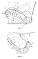
- FIGS 5 and 6 show in cross section respective an embodiment of the inner child seat in the first and the second position.
- the lower outer wall 17 is connected to the upper outer wall 10 with the hinge 13.
- a foam 23 is moulded for protecting the child in the inner child seat.
- the brace 15 is connected to the outside of the lower outer wall 17 with a hinge 28.
- On the head side of the upper outer wall 10 two rails 27 are fastened for guiding the brace 15.
- a latch 25 with pins 24 that can be inserted in holes 26.
- the brace 15 can be locked in two positions by locking the pin 21 in two positions in the slot 20.
- FIG. 7 shows a further embodiment of the inner child seat whereby a brace 29 is U-shaped instead of more or less rectangular.
- the U-shaped brace 29 is coupled to a hinge 31 of the lower body enclosure 2.
- the lower outer wall 17 and the upper outer wall 10 form a single part for instance made from sheet material with a hinge in a hinge area 30.
- the lower feet 14, the upper feet 12 and the reinforcement are also made from the sheet material so that the inner child seat can be produced in one part.
- the embodiments shown in the figures 1-7 are shown as examples.
- the brace 15, 29 is shown as being hingeable to the lower body enclosure 2. It is equally possible that the brace 15, 29 is hingeable to the upper body enclosure 6.
- the positioning of the brace 15, 29 can be done in other ways than the described rails, for instance by positioning and latching the pins 21 in slot 20 or any other way.
- the handle 9 will be used.
- the handle can be provided with a sling strap (not shown) that can be carried over the shoulder, whereby the inner child seat can rest against a hip. When not in use this sling strap is retracted in the brace 15 by an elastic cord or it can be separately fastened to the brace 15.
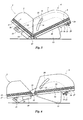
- Figures 8 and 9 diagrammatically show how the length of a shoulder strap 37 is adjusted when the inner child seat is brought from its first position to its second position.
- the child With the inner child seat in the first position as shown in figure 8 the child can be held in the inner child seat using the shoulder strap 37 with a buckle 36 is held in a clip 35, which is part of a support 34.
- the support 34 is located on the leg support 1 of the lower body enclosure 2 between the legs of the child.
- the other end of the shoulder strap 37 is guided through a strap guide 40 which is in the back support 8 and around a pin 39 and is attached with a fastener 41 on the brace 15.
- the pin 39 is part of a holder 38 which is connected to a tensioning strap 42 of which a strap end 33 is guided through a tensioning clamp 32.
- the shoulder strap 37 that holds the child against the lower body enclosure 2 and the upper body enclosure 6 when they are in the first position (the child is sitting) has a length "a".
- the strap guide 40 which might have several positions for guiding the shoulder strap 37 or might be adjustable in the upper body enclosure 6 is located such that with length "a” the child is sufficiently restrained for safety reasons and also sufficiently restrained and comfortable in the inner child seat.
- the length "a" of the shoulder strap 37 is adjusted with the tensioning strap 42 so that the distance between the pin 39 and the brace 15 is "b + c".
- the inner child seat is shown in its second position whereby the child is lying more or less on a flat surface. Due to unfolding of the lower body enclosure 2 and the upper body enclosure 6, the length of the shoulder strap 37 enclosing the child has to be increased in order that the child remains comfortable. Due to the unfolding the brace 15 moves relative the upper body enclosure 6 so that the distance between the pin 39 and the brace 15 is reduced to "c" and the length of the shoulder strap 37 between the clip 35 and the strap guide 40 is increased to "a + b". In this way the length of the shoulder strap 37 is automatically adjusted when the inner child seat is brought in the second position.
- the automatic length adjustment of the shoulder strap 37 in case of a child seat of a different design whereby an upper half and a lower half of the child seat are coupled by a hinge is also possible in situations whereby there is no brace 15.
- the end of the shoulder strap 37 is after looping around the pin 39 fastened by a fastener 41 to a coupling bar that is fastened by a pivot to the lower half.
- the coupling bar will be designed to fit under or along the sides of child seat.
- the inner child seat can be used for transporting a child by carrying the inner child seat.
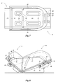
- the inner child seat can be fastened in a seat outer 43 as shown in the figures 10 and 11, figure 12 shows the seat outer 43 as fastened in a car and ready for placing the inner child seat in it.
- the brace 15 is releasable fastened on a brace support 45 of the seat outer 43.
- the brace support 45 has an opening 44 with knobs 53 (see figure 12 ) for moving guide locks 52 (see figure 12 ) releasing the brace 15 from the seat outer 43 so that the inner child seat can be taken out or lifted.
- knobs 53 in the opening 44 on both sides of the seat outer 43 there is also a control button 55 placed in the center of the seat outer 43 that moves both guide locks 52 and releases the brace 15 from the seat outer 43 on both sides.
- control button 55 there can be control buttons 55' (shown in interrupted lines) that are placed on both sides and that move both guide locks 52.
- the inner child seat can be lifted out by gripping the brace 15 in the openings 44 on both sides of the inner child seat. It is also possible to use the carrying handle 9 for lifting the inner child seat out of the seat outer 43.
- the coupling of the brace 15 to the seat outer 43 can be arranged by coupling the brace 15 at the head side, which is the side of the upper enclosure 6, and the foot side, which is the side of the lower enclosure 2, of the inner child seat to the seat outer 43 with movable hooks.
- the movable hooks hold the brace 15 in a fixed position in the seat outer 43, fixed by the shape of the seat outer 43 and/or protuberances on the seat outer 43 that fit in notches of the brace 15.
- the movable hooks thereby can either grip around the brace 15 or grip a pin in a notch in the brace 15.
- the brace 15 When either the movable hook at the head side or the movable hook at the foot side of the seat outer 43 is moved the brace 15 can be lifted at that side until the notches are free of the protuberances and after that the other hook comes free of the brace and the inner child seat can be lifted out of the seat outer 43. In this way the inner child seat can be released from the seat outer 43 with knobs on the seat outer 43 near the movable hooks at either the head side and with knobs near the movable hooks at the foot side. It will be obvious that according to a simplification instead of the hooks at both sides being movable the hooks on either the head side or the foot side can be fixed.
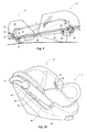
- the seat outer 43 can be fastened in a car using a hip strap 50 and a diagonal strap 48.
- the seat outer 43 is placed on a car seat 49 and positioned against a seat back 51 and the hip strap 50 and diagonal strap 48 are looped around the seat outer 43 as shown in figures 11 and 12 using guide hooks 46 and 54.
- the inner child seat is positioned in the seat outer 43 using guide locks 52 (see figure 12 ) fitting in holes in the brace 15.
- the guide locks 52 lock the inner child seat in the seat outer 43.
- Another way of mounting the seat outer 43 in a car is using a base (not shown) designed for coupling to the underside of the seat outer 43.
- the base is mounted in the car using hooks to couple the base to "Isofix" attachments in the car.
- the inner child seat with child can also be transported using a stroller.
- the stroller has a brace support and guide locks that are more or less similar to the brace support 45 and guide lock 52 as used in the seat outer 43.
- the brace support of the stroller can be tilted. By adjusting the brace support the child seat can be brought in tilt positions that are suitable for the age of the child. In this way a younger child can lay flat when transported on the stroller and an older child can sit in the child seat
Abstract
The invention concerns a device for transporting a child comprising a lower enclosure (2) supporting and/or cushioning the legs and lower part of the child and an upper enclosure (6) supporting and/or cushioning the head and shoulders of the child, whereby said lower and upper enclosures each have a bottom (1,8) and opposite each other two side walls (3,4), the device further comprising a first hinge (13) for connecting the bottoms of lower enclosure and the upper enclosure and positioning means (15) for positioning the enclosures relative to each other in a sitting position whereby the bottoms make an obtuse angle and in a lying position whereby the bottoms are approximately in one plane. In accordance with the invention the positioning means (15) comprise a brace (15) around the side walls and preferably around the bottoms of the enclosures.
Description
- The invention concerns a device for transporting a child in accordance with the preamble of
claim 1. Such a device is known inter alia fromEP 1481616 . The known device has a U-shaped carrier that is placed under both enclosures. This device is large, heavy and not easy to handle. In order to overcome these disadvantages the device is in accordance with the characterizing part ofclaim 1. In this way there is no need for further parts than the enclosures and the supporting brace for carrying a child in a safe way. As the brace supports the enclosures sideways the forces acting between the child and the transporting device are directly transferred to or from the brace and the bottoms so that side walls need not take a sideways directed load and can be very light. This makes the device easy to carry. - In accordance with an embodiment, the device is in accordance with
claim 2. This makes it easy to change the position of the enclosures from sitting position to lying position. When the brace is moved relative to the other enclosure this movement lets the enclosures rotate around the first hinge and makes them change from the sitting position to the lying position and vice versa. - In accordance with an embodiment the device is in accordance with
claim 3. In this way the brace is fastened more stable to the side walls. - In accordance with an embodiment the device is in accordance with claim 4. As a result the brace has the shape of an uninterrupted hoop which can be relatively light.
- In accordance with an embodiment the device is in accordance with
claim 5. As a result the turning points of the second hinge have a certain distance from each other which makes the second hinge more stable. - In accordance with an embodiment the device is in accordance with
claim 6. As a result, it is easy to position the brace and the enclosures in two stable positions. In this way, the user can bring the inner child seat easily from a lying position to a sitting position or vice versa. - In accordance with an embodiment the device is in accordance with
claim 7. This way the device can be made very light while the child is adequately cushioned in the enclosures. - In accordance with an embodiment the device is in accordance with
claim 8. This way the enclosures together form a smooth part that does not need fasteners for connecting the various parts. - In accordance with an embodiment the device is in accordance with
claim 9. This way the enclosures can rest directly on a table or a floor. - In accordance with an embodiment the device is in accordance with
claim 10. This makes the enclosures very light and easy to produce. - In accordance with an embodiment the device is in accordance with
claim 11. As a result it is possible to bring the device from a sitting position to a lying position or vice versa whereby there is no need to change the length of the shoulder straps as they are automatically re-adjusted due to the movement of the brace relative to the upper enclosure. - In accordance with an embodiment the device is in accordance with
claim 12. In this way the position of the straps in the upper enclosure can be adjusted in an easy way to the length of the child. - In accordance with an embodiment the device is in accordance with
claim 13. As a result the carrying handle is coupled to the strongest part of the device that supports both enclosures and when the carrying handle is positioned near the brace the enclosures can be moved from sitting position to laying position and vice versa without obstruction by the carrying handle. - In accordance with an embodiment the device is in accordance with
claim 14. As the carrying handle is shorter than half the length of the device the carrying handle is very low above the child. This makes carrying the transporting device and placing the device in a car easier. - In accordance with an embodiment the device is in accordance with
claim 15. The outer shell gives additional protection to and strengthens the enclosures so that the child in the enclosures is better protected and the enclosures can be kept very light. Also it makes it easy to place the enclosures with the child positioned in the straps in the car. - In accordance with an embodiment the device is in accordance with
claim 16. This makes coupling the enclosures to the outer shell easier as only the brace has to be coupled. - In accordance with an embodiment the device is in accordance with
claim 17. In this way the brace is coupled to the outer shell in an easy way and can be uncoupled at the side of the lower enclosure and/or at the side of the upper enclosure. - In accordance with an embodiment the device is in accordance with
claim 18. As a result enclosures with the child in it can be placed in an easy movement on a transport or support means. - In accordance with an embodiment the device is in accordance with
claim 19. As a result the device can be carried with the sling around a shoulder which makes the carrying of it easy. - The invention also concerns the clothing for the device in accordance with
claim 20. By using the clothing with side covers no material or parts of the child can come between the upper enclosure and the lower enclosure in the opening thereby preventing damage or accidents. - The invention will now be elucidated with the help of a description of one or more embodiments, using a drawing. In the drawing
-
Figure 1 shows a perspective side view of an inner child seat ready for placing a child in the inner child seat in a sitting position, -
Figure 2 shows the inner child seat offigure 1 whereby the child in the inner child seat is in a lying position, -
Figure 3 shows the inner child seat offigure 1 in a view without the protective clothing showing the structure of the various parts, -
Figure 4 shows the inner child seat offigure 2 in a view without the protective clothing, -
Figure 5 shows a simplified view of the longitudinal section of the inner child seat as shown infigure 1 , -
Figure 6 shows a simplified view of the longitudinal section of the inner child seat as shown infigure 2 , -
Figure 7 shows a bottom view of an inner child seat which is similar to the inner child seat offigure 1 and which has a U-shaped brace and a simplified hinge design, -
Figure 8 shows a simplified section view of the course and fastening of a shoulder strap that holds a child in an inner child seat when the inner child seat is in a sitting position, -
Figure 9 shows the section view offigure 8 when the inner child seat is in a lying position, -
Figure 10 shows a perspective view of the inner child seat offigure 1 without protective clothing and mounted in an outer shell ready for placing the inner child seat in a car, -
Figure 11 shows a side view of the inner child seat and outer shell place on the seat of a car, and -
Figure 12 shows a perspective view of the outer shell offigures 10 and11 when placed in a car. -
Figure 1 and 2 show a child seat also known as an infant carrier, hereafter referred to as an inner child seat. The inner child seat is designed as being suitable for new born children and/or very young children.Figure 1 shows the inner child seat in a first position whereby the inner child seat is positioned such that there is an angle between the child's' legs and its back so that the child more or less sits in the inner child seat.Figure 2 shows the inner child seat in a second position whereby the inner child seat is positioned such that the child can lay extended with its legs and back more or less in a flat plane or slightly angled under an angle of 10 - 15 degrees. - The inner child seat has a
lower body enclosure 2 and anupper body enclosure 6 which are connected in the bottom plane by ahinge 13. Thelower body enclosure 2 is more or less U-shaped with lower side supports 3 which extend above the plane of aleg support 1. Theupper body enclosure 6 also is more or less U-shaped with upper side supports 4 extending above the plane of aback support 8. Theback support 8 is considerably longer than theleg support 1 as the young child's back is longer than its legs. Thehinge 13 connects theleg support 1 and theback support 8. The side supports 4 on the top side away from thelower body enclosure 2 function as head supports 7 for sideways supporting the head of the child, which is slightly smaller than its body so that the distance between the head supports 7 is smaller than the distance between the upper side supports 4. For further protecting the head of the child there arehead cushions 5. - The outside of the
upper body enclosure 6 is formed by an upperouter wall 10, the outside of thelower body enclosure 2 is formed by the lowerouter wall 17. The upperouter wall 10 is supported by twoupper feet 12 and the lowerouter wall 17 is supported by twolower feet 14. In the first position as shown infigure 1 thelower feet 14 and theupper feet 12 can be positioned on a flat surface and then form an arc so that the inner child seat can rock on this surface. Theleg support 1 andback support 8, which are coupled with thehinge 13 are more or less perpendicular to each other so that the child can sit in the inner child seat. In this first position, the lower side supports 3, the upper side supports 4 and the head supports 7 are sideways supported by abrace 15. Thebrace 15 is hingeably connected to thelower body enclosure 2 and movably connected to theupper body enclosure 6. In the first position, shown infigure 1 , thebrace 15 is in a high position latched to theupper body enclosure 6. In the second position shown infigure 2 thebrace 15 has moved downwards along theupper body enclosure 6. In this position thelower body enclosure 2 and theupper body enclosure 6 have moved relative to one another by rotating in thehinge 13 and theleg support 1 and theback support 8 are more or less in line. It is possible that thebrace 15 is latched in the lower position on theupper body enclosure 6 or that it can be latched into one or more intermediate positions. - In
figures 1 and 2 the inner child seat is shown ready for use and is covered in the customary manner with padded clothing in order to improve comfort of the child as much as possible. The padded clothing is provided with acover pad 16 that covers the gap between thelower body enclosure 2 and theupper body enclosure 6 in the situation that the inner child seat is in the second position in order to prevent that the child's limbs being trapped in the gap between the enclosures. -
Figures 3 and 4 show the inner child seat in respectively first and second position as shown infigures 1 and 2 without the padded clothing. For guidance and support thebrace 15 is provided with apin 21 that slides in aslot 20 that is in the upper side support 4 so that thebrace 15 is guided along the side wall of the upper side support 4. In a further embodiment, the position of thebrace 15 can be fixed by locking thepin 21 in the end positions of theslot 20. Thebrace 15 is further provided with a carryinghandle 9 that is rotatable coupled to thebrace 15 by ahandle hinge 11. Thehandle hinge 11 has ahandle release knob 18 so that the carryinghandle 9 can be positioned along thebrace 15 and more or less perpendicular to thebrace 15 as indicated with interrupted lines infigure 3 whereby the inner child seat can be carried using the carryinghandle 9. - The
handle hinge 11 is connected to thebrace 15 at a distance approximately one third of the length of the inner child seat from the upper or head side of theupper body enclosure 6 so that the carryinghandle 9 is considerably shorter than half the length of the inner child seat. During carrying the inner child seat, agrip 19 in the middle of the carryinghandle 9 is, because of theshort carrying handle 9, relative low above the center of gravity of the inner child seat. This short carrying handle 9 makes it easier to carry the inner child seat close to the body and to position the inner child seat in a limited space such as the rear seat of a car. - For carrying the inner child seat (when not using the carrying handle 9) the
brace 15 is provided on both sides of the inner child seat with acavity 22. Thelower body enclosure 2 and theupper body enclosure 6 as shown infigures 3 and 4 are made from synthetic material preferably with a foam on the inside. There is no need for reinforcements in the material so that the inner child seat is very light and easy to carry as strength for protecting the child positioned in inner child seat when subject to strong forces for instance when fastened in a car is provided by thebrace 15. During use thebrace 15 is positioned along the edges of thelower side support 3, the upper side support 4 and thehead support 7 so that forces on these sides are absorbed and guided through by thebrace 15. -
Figures 5 and 6 show in cross section respective an embodiment of the inner child seat in the first and the second position. The lowerouter wall 17 is connected to the upperouter wall 10 with thehinge 13. On the insides of theseouter walls 10 and 17 afoam 23 is moulded for protecting the child in the inner child seat. Thebrace 15 is connected to the outside of the lowerouter wall 17 with ahinge 28. On the head side of the upperouter wall 10 tworails 27 are fastened for guiding thebrace 15. For positioning thebrace 15 there is alatch 25 withpins 24 that can be inserted inholes 26. As indicated earlier, in another embodiment thebrace 15 can be locked in two positions by locking thepin 21 in two positions in theslot 20. -
Figure 7 shows a further embodiment of the inner child seat whereby abrace 29 is U-shaped instead of more or less rectangular. TheU-shaped brace 29 is coupled to ahinge 31 of thelower body enclosure 2. In this embodiment the lowerouter wall 17 and the upperouter wall 10 form a single part for instance made from sheet material with a hinge in ahinge area 30. Preferably thelower feet 14, theupper feet 12 and the reinforcement are also made from the sheet material so that the inner child seat can be produced in one part. - The embodiments shown in the
figures 1-7 are shown as examples. Thebrace lower body enclosure 2. It is equally possible that thebrace upper body enclosure 6. The positioning of thebrace pins 21 inslot 20 or any other way. For carrying the inner child seat generally thehandle 9 will be used. For carrying the inner child seat over longer distances the handle can be provided with a sling strap (not shown) that can be carried over the shoulder, whereby the inner child seat can rest against a hip. When not in use this sling strap is retracted in thebrace 15 by an elastic cord or it can be separately fastened to thebrace 15. -
Figures 8 and9 diagrammatically show how the length of ashoulder strap 37 is adjusted when the inner child seat is brought from its first position to its second position. With the inner child seat in the first position as shown infigure 8 the child can be held in the inner child seat using theshoulder strap 37 with abuckle 36 is held in aclip 35, which is part of asupport 34. Thesupport 34 is located on theleg support 1 of thelower body enclosure 2 between the legs of the child. The other end of theshoulder strap 37 is guided through astrap guide 40 which is in theback support 8 and around apin 39 and is attached with afastener 41 on thebrace 15. Thepin 39 is part of aholder 38 which is connected to atensioning strap 42 of which astrap end 33 is guided through atensioning clamp 32. Theshoulder strap 37 that holds the child against thelower body enclosure 2 and theupper body enclosure 6 when they are in the first position (the child is sitting) has a length "a". Thestrap guide 40 which might have several positions for guiding theshoulder strap 37 or might be adjustable in theupper body enclosure 6 is located such that with length "a" the child is sufficiently restrained for safety reasons and also sufficiently restrained and comfortable in the inner child seat. The length "a" of theshoulder strap 37 is adjusted with thetensioning strap 42 so that the distance between thepin 39 and thebrace 15 is "b + c". - In
figure 9 the inner child seat is shown in its second position whereby the child is lying more or less on a flat surface. Due to unfolding of thelower body enclosure 2 and theupper body enclosure 6, the length of theshoulder strap 37 enclosing the child has to be increased in order that the child remains comfortable. Due to the unfolding thebrace 15 moves relative theupper body enclosure 6 so that the distance between thepin 39 and thebrace 15 is reduced to "c" and the length of theshoulder strap 37 between theclip 35 and thestrap guide 40 is increased to "a + b". In this way the length of theshoulder strap 37 is automatically adjusted when the inner child seat is brought in the second position. - The automatic length adjustment of the
shoulder strap 37 in case of a child seat of a different design whereby an upper half and a lower half of the child seat are coupled by a hinge is also possible in situations whereby there is nobrace 15. In that case the end of theshoulder strap 37 is after looping around thepin 39 fastened by afastener 41 to a coupling bar that is fastened by a pivot to the lower half. The coupling bar will be designed to fit under or along the sides of child seat. - The inner child seat can be used for transporting a child by carrying the inner child seat. For transporting the child in a car the inner child seat can be fastened in a seat outer 43 as shown in the
figures 10 and11, figure 12 shows the seat outer 43 as fastened in a car and ready for placing the inner child seat in it. Thebrace 15 is releasable fastened on abrace support 45 of the seat outer 43. Thebrace support 45 has anopening 44 with knobs 53 (seefigure 12 ) for moving guide locks 52 (seefigure 12 ) releasing thebrace 15 from the seat outer 43 so that the inner child seat can be taken out or lifted. In addition toknobs 53 in theopening 44 on both sides of the seat outer 43 there is also acontrol button 55 placed in the center of the seat outer 43 that moves both guidelocks 52 and releases thebrace 15 from the seat outer 43 on both sides. In stead of the centrally placedcontrol button 55 there can be control buttons 55' (shown in interrupted lines) that are placed on both sides and that move both guide locks 52. The inner child seat can be lifted out by gripping thebrace 15 in theopenings 44 on both sides of the inner child seat. It is also possible to use the carryinghandle 9 for lifting the inner child seat out of the seat outer 43. - In a further embodiment the coupling of the
brace 15 to the seat outer 43 can be arranged by coupling thebrace 15 at the head side, which is the side of theupper enclosure 6, and the foot side, which is the side of thelower enclosure 2, of the inner child seat to the seat outer 43 with movable hooks. In this embodiment (not shown) the movable hooks hold thebrace 15 in a fixed position in the seat outer 43, fixed by the shape of the seat outer 43 and/or protuberances on the seat outer 43 that fit in notches of thebrace 15. The movable hooks thereby can either grip around thebrace 15 or grip a pin in a notch in thebrace 15. When either the movable hook at the head side or the movable hook at the foot side of the seat outer 43 is moved thebrace 15 can be lifted at that side until the notches are free of the protuberances and after that the other hook comes free of the brace and the inner child seat can be lifted out of the seat outer 43. In this way the inner child seat can be released from the seat outer 43 with knobs on the seat outer 43 near the movable hooks at either the head side and with knobs near the movable hooks at the foot side. It will be obvious that according to a simplification instead of the hooks at both sides being movable the hooks on either the head side or the foot side can be fixed. - The seat outer 43 can be fastened in a car using a
hip strap 50 and adiagonal strap 48. The seat outer 43 is placed on acar seat 49 and positioned against a seat back 51 and thehip strap 50 anddiagonal strap 48 are looped around the seat outer 43 as shown infigures 11 and 12 using guide hooks 46 and 54. After the positioning of the seat outer 43 in the car the inner child seat is positioned in the seat outer 43 using guide locks 52 (seefigure 12 ) fitting in holes in thebrace 15. The guide locks 52 lock the inner child seat in the seat outer 43. Another way of mounting the seat outer 43 in a car is using a base (not shown) designed for coupling to the underside of the seat outer 43. The base is mounted in the car using hooks to couple the base to "Isofix" attachments in the car. - The inner child seat with child can also be transported using a stroller. Thereby the inner child seat is coupled to an interface of the stroller. The stroller has a brace support and guide locks that are more or less similar to the
brace support 45 and guidelock 52 as used in the seat outer 43. Preferably the brace support of the stroller can be tilted. By adjusting the brace support the child seat can be brought in tilt positions that are suitable for the age of the child. In this way a younger child can lay flat when transported on the stroller and an older child can sit in the child seat
Claims (20)
- Device for transporting a child comprising a lower enclosure supporting (2) and/or cushioning the legs and lower part of the child and an upper enclosure (6) supporting and/or cushioning the head and shoulders of the child, whereby said lower and upper enclosures each have a bottom (1;8) and opposite each other two side walls (3;4,7), the device further comprising a first hinge (13;30) for connecting the bottoms of lower enclosure and the upper enclosure and positioning means (15) for positioning the enclosures relative to each other in a sitting position whereby the bottoms make an obtuse angle and in a lying position whereby the bottoms are approximately in one plane characterized in that the positioning means comprise a brace (15;24) around the side walls (3; 7) and preferably around the bottoms (1,8) of the enclosures (2, 6).
- Device in accordance with claim 1 whereby the brace (15;29) is connected with a second hinge (28,31) to the one enclosure (2) and with at least one linear guide (20,21;27) to the other enclosure (6).
- Device in accordance with claim 2 whereby the brace (15,29) is connected with two linear guides (20,21) at both sides of the side walls (4) of the other enclosure (6).
- Device in accordance with claim 2 or 3 whereby the second hinge (28) connects the brace (15) to the middle of the bottom (17) of the one enclosure (2).
- Device in accordance with claim 2 or 3 whereby the second hinge (31) connects to the brace (29) at both sides of the bottom (17) of the one enclosure (2).
- Device in accordance with claim 2, 3, 4 or 5 whereby the brace (15,29) is provided with a latch (20,21; 24,25,26,27) for positioning the brace in at least two positions relative to the other enclosure (6).
- Device in accordance with one of the previous claims whereby the enclosures (2,6) are formed from thin plastic sheet material with on their inside surface foam-like cushioning material (23) which is preferably moulded onto the plastic sheet material.
- Device in accordance with claim 7 whereby the thin plastic sheet material is an uninterrupted sheet for the upper and lower enclosures (2,6) and also forms the first hinge (30).
- Device in accordance with one of the previous claims whereby near the first hinge the bottoms (1,8) both have a support (12,14) for supporting the enclosures on a flat surface.
- Device in accordance with claim 9 whereby the supports (12,14) are formed from the thin plastic sheet material forming the outside of the enclosures (2,6).
- Device in accordance with one of the previous claims whereby shoulder straps (37) for restraining the upper body of the child are guided along strap guides (40) through openings in the upper enclosure (6) and fastened to the brace (15,29), the shoulder straps being looped around a roller (39) whereby near the second hinge (28) an adjustable strap (42) connects the roller to the lower enclosure (2).
- Device in accordance with claim 11 whereby the strap guides (40) are displaceable and have positioning means on the inside and/or the outside of the upper enclosure (6).
- Device in accordance with one of the previous claims whereby the brace (15,29) has on one or both sides of the upper enclosure a third hinge (11) for swivable connecting a carrying handle (9) that can be rotated from along the brace to above the gravity centre of the child to be carried.
- Device in accordance with claim 13 whereby the carrying handle (9) has a grip (19) and the distance between the grip and the rotation axis of the third hinge (11) is shorter than half of the distance from the bottom of the lower enclosure (2) to the top of the upper enclosure (6) and preferably approximately one third of this distance.
- Device in accordance with one of the previous claims comprising an outer shell (43) with means (46,47,54) for fastening said outer shell in a car, said outer shell being designed for supporting the enclosures (2,6) and/or the brace (15;29).
- Device in accordance with claim 15 whereby the outer shell (43) has first connecting means (52,53) for coupling the outer shell and the brace (15;29) when the enclosures (1,6) are placed in the outer shell.
- Device in accordance with claim 15 or 16 whereby the outer shell (43) has protuberances that fit into notches of the brace (15) allowing relative movement of the brace in only one direction and a first brace hook at the side of the lower enclosure and a second brace hook at the side of the upper enclosure for holding the brace against the outer shell and whereby the first brace hook and/or the second brace hook is movable for releasing the brace from the outer shell.
- Device in accordance with one of the previous claims comprising a transport or support means with second connecting means suitable for coupling to the brace (15;29).
- Device in accordance with one of the previous claims whereby a sling is connectable to the brace (15;29) at connecting points and/or a sling is elastically extendable from within the brace to a defined length.
- A clothing for covering the inside of the enclosures (1,6) according to one of the previous claims, which clothing comprises a back part that covers and/or is coupled to the bottom of the upper enclosure, the first hinge and the bottom of the lower enclosure, first side parts attached to the back part and coupled to the sides of the upper enclosure, second side parts attached to the back part and coupled to sides of the lower enclosures, and two side covers that are connected to either the first side parts or the second side parts, whereby each side cover covers the opening between a side wall of the upper enclosure and a side wall of the lower enclosure.
Priority Applications (4)
| Application Number | Priority Date | Filing Date | Title |
|---|---|---|---|
| EP07104249A EP1969975A1 (en) | 2007-03-15 | 2007-03-15 | Device for transporting a child |
| US12/048,769 US7934772B2 (en) | 2007-03-15 | 2008-03-14 | Device for transporting a child |
| EP08102682A EP1969974B1 (en) | 2007-03-15 | 2008-03-17 | Device for transporting a child |
| CNA2008100861679A CN101289069A (en) | 2007-03-15 | 2008-03-17 | Device for transporting a child |
Applications Claiming Priority (1)
| Application Number | Priority Date | Filing Date | Title |
|---|---|---|---|
| EP07104249A EP1969975A1 (en) | 2007-03-15 | 2007-03-15 | Device for transporting a child |
Publications (1)
| Publication Number | Publication Date |
|---|---|
| EP1969975A1 true EP1969975A1 (en) | 2008-09-17 |
Family
ID=38325367
Family Applications (2)
| Application Number | Title | Priority Date | Filing Date |
|---|---|---|---|
| EP07104249A Withdrawn EP1969975A1 (en) | 2007-03-15 | 2007-03-15 | Device for transporting a child |
| EP08102682A Not-in-force EP1969974B1 (en) | 2007-03-15 | 2008-03-17 | Device for transporting a child |
Family Applications After (1)
| Application Number | Title | Priority Date | Filing Date |
|---|---|---|---|
| EP08102682A Not-in-force EP1969974B1 (en) | 2007-03-15 | 2008-03-17 | Device for transporting a child |
Country Status (3)
| Country | Link |
|---|---|
| US (1) | US7934772B2 (en) |
| EP (2) | EP1969975A1 (en) |
| CN (1) | CN101289069A (en) |
Cited By (1)
| Publication number | Priority date | Publication date | Assignee | Title |
|---|---|---|---|---|
| EP3628537A1 (en) * | 2014-08-29 | 2020-04-01 | CYBEX GmbH | Child seat for a motor vehicle |
Families Citing this family (11)
| Publication number | Priority date | Publication date | Assignee | Title |
|---|---|---|---|---|
| US20110175417A1 (en) * | 2010-01-18 | 2011-07-21 | Gil Peled | "Method system and device of children's seat and bed and mattress changing device angles and positions" |
| US20110193381A1 (en) * | 2010-02-09 | 2011-08-11 | Jose Salazar | Reclining child seat |
| DE202011000229U1 (en) * | 2011-01-31 | 2011-06-09 | Curt Würstl Vermögensverwaltungs-GmbH & Co. KG, 95032 | Baby carrier in the form of a bucket seat |
| DE102012108352A1 (en) * | 2012-09-07 | 2014-03-13 | Recaro Aircraft Seating Gmbh & Co. Kg | Seat energy absorption device |
| CN106218459B (en) * | 2016-08-25 | 2018-03-20 | 浙江感恩科技股份有限公司 | A kind of basket type safety seat |
| USD847520S1 (en) * | 2017-07-10 | 2019-05-07 | Cybex Gmbh | Child safety seats for motor cars |
| JP2021517086A (en) * | 2018-02-21 | 2021-07-15 | カーフォールディオ リミテッド | Child restraint system for toddlers |
| US11376999B2 (en) | 2019-07-10 | 2022-07-05 | Dorel Juvenile Group, Inc. | Infant carrier |
| NL2023469B1 (en) | 2019-07-10 | 2021-02-02 | Maxi Miliaan Bv | Child seat transporting system and safety part suitable for such a child seat transporting system |
| NL2023470B1 (en) | 2019-07-10 | 2021-02-02 | Maxi Miliaan Bv | Coupling mechanism as well as a child seat transporting system provided with at least one such a coupling mechanism |
| US11623549B2 (en) | 2019-07-25 | 2023-04-11 | Dorel Juvenile Group, Inc. | Infant carrier |
Citations (11)
| Publication number | Priority date | Publication date | Assignee | Title |
|---|---|---|---|---|
| US3051965A (en) * | 1961-02-27 | 1962-09-04 | Jerome C Szemplak | Supine bed |
| EP0296759A2 (en) * | 1987-06-25 | 1988-12-28 | Dixie Usa, Inc. | Patient mover |
| US4885200A (en) * | 1988-04-29 | 1989-12-05 | Weyerhaeuser Company | Infant car seat liner |
| WO1994012079A1 (en) * | 1992-11-30 | 1994-06-09 | Saddlebug Corporation | Folding infant restraint seat |
| FR2700452A1 (en) * | 1993-01-20 | 1994-07-22 | Mgb | Transformable structure for receiving a person's body, for example child's seat-cradle. |
| US5978992A (en) * | 1995-02-13 | 1999-11-09 | Antinori; Santino | Mattress retention bracket for adjustable beds |
| DE10253269A1 (en) * | 2002-11-15 | 2004-05-27 | Volkswagen Ag | Seat belt system for childrens safety seat, comprising vertically moving holding element located at rear of seat |
| EP1481616A1 (en) * | 2003-05-26 | 2004-12-01 | Udo Beger | Baby seat |
| US20050011005A1 (en) * | 2003-07-18 | 2005-01-20 | German Borda | Adjustable base for supporting adjustable beds of different widths |
| FR2859363A1 (en) * | 2003-09-09 | 2005-03-11 | Sandrine Charvillat | Folding seat and bed for baby has frame in two hinged sections on hollow base forming storage compartments |
| WO2005079239A2 (en) * | 2004-02-13 | 2005-09-01 | Meeker R & D, Inc. | Infant carrier and receiving base |
Family Cites Families (18)
| Publication number | Priority date | Publication date | Assignee | Title |
|---|---|---|---|---|
| US3054637A (en) * | 1960-09-06 | 1962-09-18 | Samuel M Pambello | Portable, convertible chair cradle for child |
| US3252734A (en) * | 1964-06-02 | 1966-05-24 | Berlin Daniel | Crank operated child's convertible bed and seat |
| DE1580785A1 (en) * | 1966-02-09 | 1970-12-23 | Eberhard Schroeder | Baby boy reclining chair |
| FR2423188A3 (en) * | 1976-11-15 | 1979-11-16 | Tomy Kogyo Co | Foldaway chair bed for small children - has three movable parts with locking rod for securing position |
| FR2382218A1 (en) * | 1977-03-02 | 1978-09-29 | Durand Denise | Collapsible safety baby seat - has high head rest and backrest changed from leaning back to sitting up position |
| DE2962712D1 (en) * | 1978-09-11 | 1982-06-24 | Baby Relax | Safety car seat for children |
| US4436341A (en) * | 1981-06-22 | 1984-03-13 | Maurice Converse | Infant safety car seat |
| US4786064A (en) * | 1987-07-15 | 1988-11-22 | Baghdasarian Varouj G | Convertible infant seat |
| US4762364A (en) * | 1987-08-04 | 1988-08-09 | Rock-A-Bye Restraint Company, Inc. | Child restraint device |
| US5092004A (en) * | 1988-10-11 | 1992-03-03 | Cosco, Inc, | Convertible infant restraint device |
| US5431479A (en) * | 1990-06-11 | 1995-07-11 | Leib; Roger K. | Tandem chair assembly |
| GB2284012A (en) * | 1993-11-23 | 1995-05-24 | Wang Sheng Feng | A foldable baby chair |
| US5581234A (en) * | 1995-07-31 | 1996-12-03 | Emery; Anna L. | Infant vehicle seat alarm system |
| ES1043376Y (en) * | 1998-11-10 | 2000-05-01 | Jane Sa | BODY-CRADLE. |
| EP1029735A2 (en) * | 1999-02-20 | 2000-08-23 | Britax Excelsior Limited | Infant seat and pivot joint |
| US6679552B1 (en) * | 1999-10-27 | 2004-01-20 | Aprica Kassai Kabushikikaisha | Nursery instrument |
| DE20308359U1 (en) * | 2003-05-26 | 2003-08-14 | Beger Udo | child seat |
| GB0317560D0 (en) * | 2003-07-26 | 2003-08-27 | Isaac Upton Sharon | Compact child travel seat |
-
2007
- 2007-03-15 EP EP07104249A patent/EP1969975A1/en not_active Withdrawn
-
2008
- 2008-03-14 US US12/048,769 patent/US7934772B2/en not_active Expired - Fee Related
- 2008-03-17 CN CNA2008100861679A patent/CN101289069A/en active Pending
- 2008-03-17 EP EP08102682A patent/EP1969974B1/en not_active Not-in-force
Patent Citations (11)
| Publication number | Priority date | Publication date | Assignee | Title |
|---|---|---|---|---|
| US3051965A (en) * | 1961-02-27 | 1962-09-04 | Jerome C Szemplak | Supine bed |
| EP0296759A2 (en) * | 1987-06-25 | 1988-12-28 | Dixie Usa, Inc. | Patient mover |
| US4885200A (en) * | 1988-04-29 | 1989-12-05 | Weyerhaeuser Company | Infant car seat liner |
| WO1994012079A1 (en) * | 1992-11-30 | 1994-06-09 | Saddlebug Corporation | Folding infant restraint seat |
| FR2700452A1 (en) * | 1993-01-20 | 1994-07-22 | Mgb | Transformable structure for receiving a person's body, for example child's seat-cradle. |
| US5978992A (en) * | 1995-02-13 | 1999-11-09 | Antinori; Santino | Mattress retention bracket for adjustable beds |
| DE10253269A1 (en) * | 2002-11-15 | 2004-05-27 | Volkswagen Ag | Seat belt system for childrens safety seat, comprising vertically moving holding element located at rear of seat |
| EP1481616A1 (en) * | 2003-05-26 | 2004-12-01 | Udo Beger | Baby seat |
| US20050011005A1 (en) * | 2003-07-18 | 2005-01-20 | German Borda | Adjustable base for supporting adjustable beds of different widths |
| FR2859363A1 (en) * | 2003-09-09 | 2005-03-11 | Sandrine Charvillat | Folding seat and bed for baby has frame in two hinged sections on hollow base forming storage compartments |
| WO2005079239A2 (en) * | 2004-02-13 | 2005-09-01 | Meeker R & D, Inc. | Infant carrier and receiving base |
Cited By (1)
| Publication number | Priority date | Publication date | Assignee | Title |
|---|---|---|---|---|
| EP3628537A1 (en) * | 2014-08-29 | 2020-04-01 | CYBEX GmbH | Child seat for a motor vehicle |
Also Published As
| Publication number | Publication date |
|---|---|
| EP1969974B1 (en) | 2012-08-22 |
| US7934772B2 (en) | 2011-05-03 |
| EP1969974A3 (en) | 2009-12-02 |
| US20080231098A1 (en) | 2008-09-25 |
| EP1969974A2 (en) | 2008-09-17 |
| CN101289069A (en) | 2008-10-22 |
Similar Documents
| Publication | Publication Date | Title |
|---|---|---|
| EP1969974B1 (en) | Device for transporting a child | |
| US4717056A (en) | Infant carrying apparatus | |
| US5431478A (en) | Convertible baby carrier | |
| US3563600A (en) | Infant safety car seat | |
| US5092004A (en) | Convertible infant restraint device | |
| US5267680A (en) | Carrying sling for infant carrier or car seat | |
| JP3148150B2 (en) | Baby holder combined use waist bag | |
| CA2184323C (en) | Baby holder | |
| EP2036767B1 (en) | Child seat | |
| AU2014289980A1 (en) | A combination of child carrier and stroller | |
| US8641077B2 (en) | Stroller with a receiving frame and support straps for receiving car seats | |
| GB2268394A (en) | "Infant seat with interchangeable mountings" | |
| US11173937B2 (en) | Seat cushion | |
| CN214905412U (en) | Child carrier for carrying a child on a user's shoulder | |
| EP2801514A1 (en) | A bicycle child seat | |
| EP3500450A1 (en) | Child safety seat | |
| US20120175920A1 (en) | Supplemental Support for Infant Carrier Handle | |
| WO2018197875A1 (en) | Child carrier | |
| US11963623B2 (en) | Adjustable baby bouncer | |
| WO2012048297A2 (en) | Stroller with a receiving frame and support straps for receiving a car seat | |
| GB2352623A (en) | Inter-convertible highchair/ vehicle child seat | |
| EP1175858A2 (en) | Carrying device for children | |
| GB2166691A (en) | An infant carriage | |
| US10967762B2 (en) | Child safety seat | |
| US11344137B1 (en) | Convertible infant seat |
Legal Events
| Date | Code | Title | Description |
|---|---|---|---|
| PUAI | Public reference made under article 153(3) epc to a published international application that has entered the european phase |
Free format text: ORIGINAL CODE: 0009012 |
|
| AK | Designated contracting states |
Kind code of ref document: A1 Designated state(s): AT BE BG CH CY CZ DE DK EE ES FI FR GB GR HU IE IS IT LI LT LU LV MC MT NL PL PT RO SE SI SK TR |
|
| AX | Request for extension of the european patent |
Extension state: AL BA HR MK RS |
|
| AKX | Designation fees paid | ||
| REG | Reference to a national code |
Ref country code: DE Ref legal event code: 8566 |
|
| STAA | Information on the status of an ep patent application or granted ep patent |
Free format text: STATUS: THE APPLICATION IS DEEMED TO BE WITHDRAWN |
|
| 18D | Application deemed to be withdrawn |
Effective date: 20090318 |