EP1967790A1 - Light with heater - Google Patents
Light with heater Download PDFInfo
- Publication number
- EP1967790A1 EP1967790A1 EP08151636A EP08151636A EP1967790A1 EP 1967790 A1 EP1967790 A1 EP 1967790A1 EP 08151636 A EP08151636 A EP 08151636A EP 08151636 A EP08151636 A EP 08151636A EP 1967790 A1 EP1967790 A1 EP 1967790A1
- Authority
- EP
- European Patent Office
- Prior art keywords
- air
- housing
- light fixture
- air channel
- light
- Prior art date
- Legal status (The legal status is an assumption and is not a legal conclusion. Google has not performed a legal analysis and makes no representation as to the accuracy of the status listed.)
- Withdrawn
Links
Images

Classifications
-
- F—MECHANICAL ENGINEERING; LIGHTING; HEATING; WEAPONS; BLASTING
- F21—LIGHTING
- F21V—FUNCTIONAL FEATURES OR DETAILS OF LIGHTING DEVICES OR SYSTEMS THEREOF; STRUCTURAL COMBINATIONS OF LIGHTING DEVICES WITH OTHER ARTICLES, NOT OTHERWISE PROVIDED FOR
- F21V33/00—Structural combinations of lighting devices with other articles, not otherwise provided for
- F21V33/0088—Ventilating systems
- F21V33/0092—Ventilating systems with heating or cooling devices
-
- F—MECHANICAL ENGINEERING; LIGHTING; HEATING; WEAPONS; BLASTING
- F21—LIGHTING
- F21V—FUNCTIONAL FEATURES OR DETAILS OF LIGHTING DEVICES OR SYSTEMS THEREOF; STRUCTURAL COMBINATIONS OF LIGHTING DEVICES WITH OTHER ARTICLES, NOT OTHERWISE PROVIDED FOR
- F21V29/00—Protecting lighting devices from thermal damage; Cooling or heating arrangements specially adapted for lighting devices or systems
- F21V29/90—Heating arrangements
-
- F—MECHANICAL ENGINEERING; LIGHTING; HEATING; WEAPONS; BLASTING
- F24—HEATING; RANGES; VENTILATING
- F24H—FLUID HEATERS, e.g. WATER OR AIR HEATERS, HAVING HEAT-GENERATING MEANS, e.g. HEAT PUMPS, IN GENERAL
- F24H3/00—Air heaters
- F24H3/02—Air heaters with forced circulation
- F24H3/04—Air heaters with forced circulation the air being in direct contact with the heating medium, e.g. electric heating element
- F24H3/0405—Air heaters with forced circulation the air being in direct contact with the heating medium, e.g. electric heating element using electric energy supply, e.g. the heating medium being a resistive element; Heating by direct contact, i.e. with resistive elements, electrodes and fins being bonded together without additional element in-between
- F24H3/0411—Air heaters with forced circulation the air being in direct contact with the heating medium, e.g. electric heating element using electric energy supply, e.g. the heating medium being a resistive element; Heating by direct contact, i.e. with resistive elements, electrodes and fins being bonded together without additional element in-between for domestic or space-heating systems
Definitions
- This invention relates generally to light fixtures, and more particularly to light fixtures having heating capabilities.
- Lighting fixtures have existed for many years. Recently, some lighting fixtures have incorporated heaters to warm the surrounding air. These light fixtures are typically placed in a bathroom so as to heat the room in order to make it more comfortable for people after taking a shower or bath. As such, these light fixtures are not designed to blend into the more formal aesthetics of other rooms within a typical home. Accordingly, it is seen that a need remains for a light fixture that can provide heat but which is unobtrusive and easy to maintain. It is to the provision of such therefore that the present invention is primarily directed.
- a light fixture in a preferred form of the invention, comprises an upper housing having an upper wall, a bottom wall having an opening therethrough, and side walls which in combination with the upper wall and the bottom wall define an air channel.
- the upper housing also includes an airflow ring positioned adjacent the air channel.
- the airflow ring includes at least one air intake hole and at least one air exhaust hole.
- the light fixture also has a light diffusor coupled to the upper housing, a light source coupled to the housing, and a heat source coupled to the housing to heat air passing through the housing air channel.
- the heat source also including a fan for creating an airstream.
- the actuation of the fan draws air into the light fixture through the air intake holes, through the central opening in the bottom wall and into the air channel, and exits the light fixture through the exhaust hole within the airflow ring, and whereby the heat source heats the airstream created by the fan.
- the light fixture 10 includes an upper housing 11, a translucent shade or light diffusor 12, a light source 13, and a heating source 14.
- the upper housing 11 includes an upper wall, shown in the form of a mounting plate 17 adapted to be mounted to the ceiling or junction box of a structure in conventional fashion.
- the upper housing 11 also includes two oppositely disposed side walls 18, a bottom wall 19 spanning the side walls 18, and an annular airflow ring 21 positioned about the side walls 18 and coupled to the light diffusor 12.
- the bottom wall 19 has a central opening 23 therein.
- the airflow ring 21 has a plurality of air exhaust holes 24 generally positioned between the ends of the two sidewalls 18 and a plurality of air intake holes 25 positioned outboard of the side walls 18.
- the mounting plate 17, bottom wall 19, and two side walls 18 form an air channel 28 having an air intake (central opening 23) in fluid communication with airflow ring intake holes 25 and two oppositely disposed air exits 26 positioned closely adjacent and in fluid communication with the exhaust holes 24 of the airflow ring.
- the light source 13 includes a light socket 35 mounted to the housing bottom wall 19.
- the light socket 35 is electrically coupled to electrical wires which are coupleable to the electric wires within a home in conventional fashion.
- a light bulb 36 is mounted within the light socket 35.
- the heat source 14 includes a pair of heating elements 38 mounted within the airflow channel 28 opposite sides of central opening 23.
- the heating elements 38 may be positive temperature coefficient heaters (PTC heaters).
- the heat source 14 also includes a motorized fan 39 in fluid communication with the bottom wall opening 23 to create an air flow, as indicated by the arrows in the drawings, which enters the light fixture 10 through the air intake holes 25 of the airflow ring, flows through the central opening 23, through the fan 39, through the heating elements 38, and exits through the exhaust holes 24 in the airflow ring.
- the heating elements 38 and motorized fan 39 are coupled to the home wiring in conventional fashion.
- the light fixture may be used as a light, as a heater, or as both a light and a heater.
- the light source and/or heat source may be supplied with an electric current through the electrical wires through any conventional switch, such as a wall switch, a switch mounted to the device itself such as a pull cord switch, or a remote controlled switch such as an RF control circuit.
- the fan 39 creates and airstream that is heated by the heating element 38 and is passed through air channel 28 and expelled from the housing 11 through the airflow ring exhaust holes 24.
- the exhaust holes 24 within the airflow ring 21 allow the heated air to be directed downwardly to efficiently heat a room, rather than being directed upwardly towards the ceiling.
- the light fixture of the present invention may includes light fixtures coupled to ceiling fans, rather than directly to the ceiling or wall of a structure.
- the upper wall could be any wall and is therefore not limited to the configuration of a mounting plate shown in the preferred embodiment.
- other types of electric fans and electric heaters may be utilized as an alternative to those shown in the preferred embodiment.
- the airflow ring may be configured in any shape and is therefore not limited to the annular appearance of the preferred embodiment. As such, the term airflow ring may denote any shape, such as a square, rectangle, oval, polygon, or other shape, including, but not limited to circular shapes.
Abstract
Description
- This invention relates generally to light fixtures, and more particularly to light fixtures having heating capabilities.
- Lighting fixtures have existed for many years. Recently, some lighting fixtures have incorporated heaters to warm the surrounding air. These light fixtures are typically placed in a bathroom so as to heat the room in order to make it more comfortable for people after taking a shower or bath. As such, these light fixtures are not designed to blend into the more formal aesthetics of other rooms within a typical home.
Accordingly, it is seen that a need remains for a light fixture that can provide heat but which is unobtrusive and easy to maintain. It is to the provision of such therefore that the present invention is primarily directed. - In a preferred form of the invention, a light fixture comprises an upper housing having an upper wall, a bottom wall having an opening therethrough, and side walls which in combination with the upper wall and the bottom wall define an air channel. The upper housing also includes an airflow ring positioned adjacent the air channel. The airflow ring includes at least one air intake hole and at least one air exhaust hole. The light fixture also has a light diffusor coupled to the upper housing, a light source coupled to the housing, and a heat source coupled to the housing to heat air passing through the housing air channel. The heat source also including a fan for creating an airstream. With this construction, the actuation of the fan draws air into the light fixture through the air intake holes, through the central opening in the bottom wall and into the air channel, and exits the light fixture through the exhaust hole within the airflow ring, and whereby the heat source heats the airstream created by the fan.
-
-
Fig. 1 is a top view of a light fixture of the present invention. -
Fig. 2 is a front view of the light fixture ofFig. 1 . -
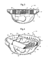
Fig. 3 is a side view of the light fixture ofFig. 1 . -
Fig. 4 is a perspective view of a portion of the light fixture ofFig. 1 . - With reference next to the drawings, there is shown a
light fixture 10 in a preferred form of the invention. Thelight fixture 10 includes anupper housing 11, a translucent shade orlight diffusor 12, alight source 13, and aheating source 14. - The
upper housing 11 includes an upper wall, shown in the form of amounting plate 17 adapted to be mounted to the ceiling or junction box of a structure in conventional fashion. Theupper housing 11 also includes two oppositely disposedside walls 18, abottom wall 19 spanning theside walls 18, and anannular airflow ring 21 positioned about theside walls 18 and coupled to thelight diffusor 12. Thebottom wall 19 has acentral opening 23 therein. Theairflow ring 21 has a plurality ofair exhaust holes 24 generally positioned between the ends of the twosidewalls 18 and a plurality ofair intake holes 25 positioned outboard of theside walls 18. Themounting plate 17,bottom wall 19, and twoside walls 18 form anair channel 28 having an air intake (central opening 23) in fluid communication with airflowring intake holes 25 and two oppositely disposed air exits 26 positioned closely adjacent and in fluid communication with theexhaust holes 24 of the airflow ring. - The
light source 13 includes alight socket 35 mounted to thehousing bottom wall 19. Thelight socket 35 is electrically coupled to electrical wires which are coupleable to the electric wires within a home in conventional fashion. Alight bulb 36 is mounted within thelight socket 35. - The
heat source 14 includes a pair ofheating elements 38 mounted within theairflow channel 28 opposite sides ofcentral opening 23. Theheating elements 38 may be positive temperature coefficient heaters (PTC heaters). Theheat source 14 also includes amotorized fan 39 in fluid communication with the bottom wall opening 23 to create an air flow, as indicated by the arrows in the drawings, which enters thelight fixture 10 through theair intake holes 25 of the airflow ring, flows through thecentral opening 23, through thefan 39, through theheating elements 38, and exits through theexhaust holes 24 in the airflow ring. Theheating elements 38 andmotorized fan 39 are coupled to the home wiring in conventional fashion. - In use, the light fixture may be used as a light, as a heater, or as both a light and a heater. The light source and/or heat source may be supplied with an electric current through the electrical wires through any conventional switch, such as a wall switch, a switch mounted to the device itself such as a pull cord switch, or a remote controlled switch such as an RF control circuit. During use as a heater or as a combination light and heater, the
fan 39 creates and airstream that is heated by theheating element 38 and is passed throughair channel 28 and expelled from thehousing 11 through the airflowring exhaust holes 24. - The
exhaust holes 24 within theairflow ring 21 allow the heated air to be directed downwardly to efficiently heat a room, rather than being directed upwardly towards the ceiling. - It should be understood that the light fixture of the present invention may includes light fixtures coupled to ceiling fans, rather than directly to the ceiling or wall of a structure. As such, the upper wall could be any wall and is therefore not limited to the configuration of a mounting plate shown in the preferred embodiment. It should also be understood that other types of electric fans and electric heaters may be utilized as an alternative to those shown in the preferred embodiment. Lastly, it should be understood that the airflow ring may be configured in any shape and is therefore not limited to the annular appearance of the preferred embodiment. As such, the term airflow ring may denote any shape, such as a square, rectangle, oval, polygon, or other shape, including, but not limited to circular shapes.
- It thus is seen that a light fixture is now provided which provides heat but which is unobtrusive. While this invention has been described in detail with particular reference to the preferred embodiment thereof, it should be understood that many modification, additions and deletions, may be made thereto without departure from the spirit and scope of the invention as set forth in the following claims.
Claims (10)
- A light fixture comprising,an upper housing having an upper wall, a bottom wall having an opening therethrough, and side walls which in combination with said upper wall and said bottom wall define an air channel, the upper housing also includes an airflow ring positioned adjacent said air channel, said airflow ring including at least one air intake hole and at least one air exhaust hole;a light diffusor coupled to said upper housing;a light source coupled to said housing;a heat source coupled to said housing to heat air passing through said housing air channel, said heat source includes a fan for creating an airstream through said air channel,whereby the actuation of the fan draws air into the light fixture through the air intake holes, through the central opening in the bottom wall and into the air channel, and exits the light fixture through the exhaust hole within the airflow ring, and whereby the heat source heats the airstream created by the fan.
- The light fixture of claim 1 wherein said airflow ring includes at least two oppositely disposed air exhaust holes.
- The light fixture of claim 1 or claim 2 wherein said airflow ring includes at least two oppositely disposed air intake holes.
- The light fixture of claim 2 wherein said airflow ring also includes at least two oppositely disposed air exhaust holes.
- The light fixture of any one of the preceding claims wherein said heat source is a positive temperature coefficient heater.
- The light fixture of any one of the preceding claims wherein said fan is a centrifugal type fan.
- The light fixture of any one of the preceding claims wherein said heat source is positioned within said air channel.
- A light fixture mountable to an overlying structure, the light fixture comprising,a housing having an internal air channel extending from an air inlet and at least one air exit, said housing also including an external housing ring having at least one air inlet hole in fluid communication with said air channel air inlet and at least one air exhaust hole in fluid communication with said air channel air exit;a light source coupled to said housing;a heat source positioned to heat an airstream passing through said housing air channel; anda fan adapted to create an airstream through said air channel,whereby an airstream passing through the housing is heated by the heat source and expelled from the exhaust hole in the housing ring.
- The light fixture of claim 8 wherein said housing ring includes at least two oppositely disposed exhaust holes.
- The light fixture of claim 8 or claim 9 wherein said heat source is a positive temperature coefficient heater;optionally wherein a light diffusor is coupled to said housingand optionally wherein said heat source is positioned within said air channel.
Applications Claiming Priority (1)
| Application Number | Priority Date | Filing Date | Title |
|---|---|---|---|
| US11/713,872 US7500760B2 (en) | 2007-03-04 | 2007-03-04 | Light with heater |
Publications (1)
| Publication Number | Publication Date |
|---|---|
| EP1967790A1 true EP1967790A1 (en) | 2008-09-10 |
Family
ID=39453064
Family Applications (1)
| Application Number | Title | Priority Date | Filing Date |
|---|---|---|---|
| EP08151636A Withdrawn EP1967790A1 (en) | 2007-03-04 | 2008-02-19 | Light with heater |
Country Status (5)
| Country | Link |
|---|---|
| US (1) | US7500760B2 (en) |
| EP (1) | EP1967790A1 (en) |
| CN (1) | CN101255982A (en) |
| CA (1) | CA2621765A1 (en) |
| TW (1) | TW200905134A (en) |
Cited By (1)
| Publication number | Priority date | Publication date | Assignee | Title |
|---|---|---|---|---|
| EP2789926A1 (en) * | 2013-04-12 | 2014-10-15 | EL-Björn AB | Fan heater |
Families Citing this family (16)
| Publication number | Priority date | Publication date | Assignee | Title |
|---|---|---|---|---|
| US7639928B2 (en) * | 2007-03-30 | 2009-12-29 | Carl Garfield Coke | 360° portable electric space heater |
| US7845831B2 (en) * | 2007-04-26 | 2010-12-07 | Hunter Fan Company | Light with heater |
| WO2010135789A1 (en) * | 2009-05-29 | 2010-12-02 | Steven Neorcsik | Lighting unit |
| US8382332B2 (en) | 2010-10-11 | 2013-02-26 | Broan NuTone, LLC | Lighting and ventilating system and method |
| US8967832B2 (en) * | 2010-10-11 | 2015-03-03 | Broan-Nutone Llc | Lighting and ventilating system and method |
| USD772846S1 (en) * | 2011-02-18 | 2016-11-29 | Sony Corporation | Combined headphone and audio player |
| US9441634B2 (en) | 2013-01-11 | 2016-09-13 | Daniel S. Spiro | Integrated ceiling device with mechanical arrangement for a light source |
| US20140254135A1 (en) * | 2013-03-08 | 2014-09-11 | Shat-R-Shield, Inc. | Light-emitting diode light and heat device |
| EP2806209B1 (en) | 2013-05-24 | 2019-03-20 | Holophane Europe Ltd. | LED luminaire with multiple vents for promoting vertical ventilation |
| US20150104159A1 (en) * | 2013-10-16 | 2015-04-16 | Restless Noggins Design, Llc | Heating and cooling apparatus |
| JP6253014B2 (en) * | 2013-12-27 | 2017-12-27 | 株式会社パアグ | Lighting device with heating function |
| GB201509767D0 (en) * | 2015-06-05 | 2015-07-22 | Europ Thermodynamics Ltd | A lamp |
| US10791590B2 (en) | 2016-02-01 | 2020-09-29 | Hatco Corporation | Food product temperature regulation |
| US20180202637A1 (en) * | 2017-01-17 | 2018-07-19 | Abl Ip Holding Llc | Mounting system for light fixture |
| USD832487S1 (en) | 2017-01-17 | 2018-10-30 | Abl Ip Holding Llc | Light fixture |
| CN113685762B (en) * | 2021-09-07 | 2023-09-05 | 福建卓上科技股份有限公司 | Durable street lamp capable of preventing temperature difference |
Citations (2)
| Publication number | Priority date | Publication date | Assignee | Title |
|---|---|---|---|---|
| US3068341A (en) * | 1960-03-28 | 1962-12-11 | Ralph G Ortiz | Ceiling light heater |
| US4681024A (en) * | 1986-07-29 | 1987-07-21 | Fasco Industries, Inc. | Combination heater-light-ventilator unit |
Family Cites Families (22)
| Publication number | Priority date | Publication date | Assignee | Title |
|---|---|---|---|---|
| US2010322A (en) | 1931-04-08 | 1935-08-06 | Riddell Frank | Combined lighting and ventilating fixture |
| US2189008A (en) | 1937-08-07 | 1940-02-06 | Franz J Kurth | Ventilating device |
| US2689906A (en) | 1951-02-10 | 1954-09-21 | Nu Tone Inc | Ceiling heater and ventilator |
| US3025379A (en) | 1958-07-14 | 1962-03-13 | Emerson Pryne Company | Combined electric heater and light fixture |
| US3141086A (en) | 1961-09-27 | 1964-07-14 | Infrared Corp Of America | Infrared heating and illuminating fixture |
| US3786233A (en) | 1972-08-18 | 1974-01-15 | Fasco Industries | Infrared heater and ventilator unit |
| US3958100A (en) | 1974-01-11 | 1976-05-18 | Ventrola Manufacturing Company | Means for preventing heat build-up in a wall-mounted room ventilator |
| US5021932A (en) | 1989-05-17 | 1991-06-04 | Fasco Industries, Inc. | Safety device for combined ventilator/light unit |
| US5333235A (en) | 1990-07-19 | 1994-07-26 | James Ryder | Electric heater assembly for attachment to ceiling fans |
| US5077825A (en) | 1991-03-12 | 1991-12-31 | Ernest Monrose | Space heater mounted to ceiling fan |
| US5425126A (en) | 1993-06-14 | 1995-06-13 | Lee; Michael A. | Ceiling fan heater with heater housing |
| US5668920A (en) | 1996-01-17 | 1997-09-16 | Pelonis Usa Ltd. | Ceiling fan with attachable heater housing having an additional fan therein |
| USD381074S (en) | 1996-03-18 | 1997-07-15 | Pelonis USA, Ltd. | Ceiling fan heater |
| USD404123S (en) | 1996-10-23 | 1999-01-12 | Pelonis Kosta L | Ceiling fan heater |
| US5909534A (en) * | 1998-02-12 | 1999-06-01 | Ko; Li-Sheng | Ventilator with far infrared generators |
| USD423094S (en) * | 1998-11-05 | 2000-04-18 | Mary Rodnell | Child safety fan cover |
| US6631243B2 (en) | 1998-11-16 | 2003-10-07 | Kenneth H. Reiker | Air recirculating and heating device |
| US6438322B1 (en) | 1998-11-16 | 2002-08-20 | Kenneth H. Reiker | Ceiling fan with attached heater and secondary fan |
| US6240247B1 (en) | 1998-11-20 | 2001-05-29 | Reiker Room Conditioner Llc | Ceiling fan with attached heater and secondary fan |
| US6751406B2 (en) | 1998-11-16 | 2004-06-15 | Reiker Room Conditioners, Llc | Ceiling mounted heating device and method therefor |
| USD435094S (en) | 2000-03-14 | 2000-12-12 | Chien Luen Industries Co., Ltd. | Heater for use with a ceiling fan |
| AU2003205508A1 (en) * | 2002-01-07 | 2003-07-24 | Patent - Treuhand - Gesellschaft Fur Elektrische Gluhlampen Mbh | Lamp |
-
2007
- 2007-03-04 US US11/713,872 patent/US7500760B2/en active Active
-
2008
- 2008-02-19 CA CA002621765A patent/CA2621765A1/en not_active Abandoned
- 2008-02-19 EP EP08151636A patent/EP1967790A1/en not_active Withdrawn
- 2008-02-27 TW TW097106852A patent/TW200905134A/en unknown
- 2008-02-29 CN CN200810006386.1A patent/CN101255982A/en active Pending
Patent Citations (2)
| Publication number | Priority date | Publication date | Assignee | Title |
|---|---|---|---|---|
| US3068341A (en) * | 1960-03-28 | 1962-12-11 | Ralph G Ortiz | Ceiling light heater |
| US4681024A (en) * | 1986-07-29 | 1987-07-21 | Fasco Industries, Inc. | Combination heater-light-ventilator unit |
Cited By (1)
| Publication number | Priority date | Publication date | Assignee | Title |
|---|---|---|---|---|
| EP2789926A1 (en) * | 2013-04-12 | 2014-10-15 | EL-Björn AB | Fan heater |
Also Published As
| Publication number | Publication date |
|---|---|
| CN101255982A (en) | 2008-09-03 |
| CA2621765A1 (en) | 2008-09-04 |
| US20080212308A1 (en) | 2008-09-04 |
| US7500760B2 (en) | 2009-03-10 |
| TW200905134A (en) | 2009-02-01 |
Similar Documents
| Publication | Publication Date | Title |
|---|---|---|
| US7500760B2 (en) | Light with heater | |
| AU708079B2 (en) | Dual fan room heater | |
| US8864447B1 (en) | Low-profile, ceiling-mounted fan | |
| US7455432B2 (en) | Lighting and ventilating apparatus and method | |
| JP5334065B2 (en) | Modular heat exchange system for use in centralized heat exchange equipment in buildings | |
| US11215188B2 (en) | Apparatus including a combination of a ceiling fan and a heater with light effects | |
| US7748861B2 (en) | Light with heater | |
| US7845831B2 (en) | Light with heater | |
| KR20110005268U (en) | A ventilating apparatus having illumination lamp | |
| US7914163B2 (en) | Ventilation fan and light | |
| CA2628796A1 (en) | Light with heater | |
| CN213119274U (en) | Integrated bathroom heater with good air exhaust performance | |
| JP2010067348A (en) | Light with heater | |
| KR200304506Y1 (en) | Fan Heater | |
| CN115507411A (en) | Heating device | |
| KR20020093715A (en) | Fan heater | |
| KR20110054743A (en) | Electric hot-air furnace |
Legal Events
| Date | Code | Title | Description |
|---|---|---|---|
| PUAI | Public reference made under article 153(3) epc to a published international application that has entered the european phase |
Free format text: ORIGINAL CODE: 0009012 |
|
| AK | Designated contracting states |
Kind code of ref document: A1 Designated state(s): AT BE BG CH CY CZ DE DK EE ES FI FR GB GR HR HU IE IS IT LI LT LU LV MC MT NL NO PL PT RO SE SI SK TR |
|
| AX | Request for extension of the european patent |
Extension state: AL BA MK RS |
|
| 17P | Request for examination filed |
Effective date: 20090309 |
|
| AKX | Designation fees paid |
Designated state(s): AT BE BG CH CY CZ DE DK EE ES FI FR GB GR HR HU IE IS IT LI LT LU LV MC MT NL NO PL PT RO SE SI SK TR |
|
| RAP1 | Party data changed (applicant data changed or rights of an application transferred) |
Owner name: HUNTER FAN COMPANY |
|
| STAA | Information on the status of an ep patent application or granted ep patent |
Free format text: STATUS: THE APPLICATION HAS BEEN WITHDRAWN |
|
| 18W | Application withdrawn |
Effective date: 20100125 |