EP1965362A2 - Intrusion warning and reporting network - Google Patents
Intrusion warning and reporting network Download PDFInfo
- Publication number
- EP1965362A2 EP1965362A2 EP08100129A EP08100129A EP1965362A2 EP 1965362 A2 EP1965362 A2 EP 1965362A2 EP 08100129 A EP08100129 A EP 08100129A EP 08100129 A EP08100129 A EP 08100129A EP 1965362 A2 EP1965362 A2 EP 1965362A2
- Authority
- EP
- European Patent Office
- Prior art keywords
- intrusion
- controller
- sensor
- user
- screen
- Prior art date
- Legal status (The legal status is an assumption and is not a legal conclusion. Google has not performed a legal analysis and makes no representation as to the accuracy of the status listed.)
- Withdrawn
Links
- 238000001514 detection method Methods 0.000 claims abstract description 15
- 238000004891 communication Methods 0.000 claims description 11
- 238000012544 monitoring process Methods 0.000 claims description 3
- 238000000034 method Methods 0.000 claims description 2
- 230000001413 cellular effect Effects 0.000 claims 1
- 230000000007 visual effect Effects 0.000 description 3
- 241001465754 Metazoa Species 0.000 description 2
- 230000006378 damage Effects 0.000 description 2
- 238000010586 diagram Methods 0.000 description 2
- 238000003384 imaging method Methods 0.000 description 2
- 238000012986 modification Methods 0.000 description 2
- 230000004048 modification Effects 0.000 description 2
- 241000876446 Lanthanotidae Species 0.000 description 1
- 208000027418 Wounds and injury Diseases 0.000 description 1
- 230000009286 beneficial effect Effects 0.000 description 1
- 208000014674 injury Diseases 0.000 description 1
- 230000002452 interceptive effect Effects 0.000 description 1
- 230000002285 radioactive effect Effects 0.000 description 1
- 230000001953 sensory effect Effects 0.000 description 1
- 210000000707 wrist Anatomy 0.000 description 1
Images

Classifications
-
- G—PHYSICS
- G08—SIGNALLING
- G08B—SIGNALLING OR CALLING SYSTEMS; ORDER TELEGRAPHS; ALARM SYSTEMS
- G08B25/00—Alarm systems in which the location of the alarm condition is signalled to a central station, e.g. fire or police telegraphic systems
- G08B25/14—Central alarm receiver or annunciator arrangements
-
- G—PHYSICS
- G08—SIGNALLING
- G08B—SIGNALLING OR CALLING SYSTEMS; ORDER TELEGRAPHS; ALARM SYSTEMS
- G08B13/00—Burglar, theft or intruder alarms
- G08B13/22—Electrical actuation
- G08B13/24—Electrical actuation by interference with electromagnetic field distribution
- G08B13/2491—Intrusion detection systems, i.e. where the body of an intruder causes the interference with the electromagnetic field
-
- G—PHYSICS
- G08—SIGNALLING
- G08B—SIGNALLING OR CALLING SYSTEMS; ORDER TELEGRAPHS; ALARM SYSTEMS
- G08B25/00—Alarm systems in which the location of the alarm condition is signalled to a central station, e.g. fire or police telegraphic systems
- G08B25/009—Signalling of the alarm condition to a substation whose identity is signalled to a central station, e.g. relaying alarm signals in order to extend communication range
-
- G—PHYSICS
- G08—SIGNALLING
- G08B—SIGNALLING OR CALLING SYSTEMS; ORDER TELEGRAPHS; ALARM SYSTEMS
- G08B25/00—Alarm systems in which the location of the alarm condition is signalled to a central station, e.g. fire or police telegraphic systems
- G08B25/01—Alarm systems in which the location of the alarm condition is signalled to a central station, e.g. fire or police telegraphic systems characterised by the transmission medium
- G08B25/10—Alarm systems in which the location of the alarm condition is signalled to a central station, e.g. fire or police telegraphic systems characterised by the transmission medium using wireless transmission systems
Definitions
- the present invention relates generally to intrusion detection and warning. More particularly, the present invention relates to a network-based intrusion warning and reporting system and method.
- Security systems are typically deployed in homes and commercial buildings to prevent theft, damage, and injury to persons within the buildings. These systems typically include various alarm components which communicate to a central controller. Once one of these alarm components, such as a sensor, detects an intrusion, a transmitter associated with the sensor transmits signals to the central controller. The central controller then alerts a user that an intrusion has occurred. The central controller may alert a user of an intrusion via the user's cell phone. The central controller traditionally alerts a user by either a vibration, a repeating noise, or a simple visual, such as a flashing light.
- the surveillance networks currently available do not provide the information desired for applications such as a hostile military environment.
- a military application it is not sufficient to merely be alerted of an intrusion into an area under surveillance, a user also needs to know location information of the intrusion. With location information, the intruder can be properly tracked and caught, if necessary. This location information is desirable and beneficial for other applications as well, such as home security, industrial security, and the protection of penitentiaries.
- the present invention overcomes many of the disadvantages of the prior art by providing an intrusion warning and reporting network designed to detect intrusions in the area, to inform users monitoring the area when an intrusion has occurred, and to inform the users of the location of the intrusion.
- the intrusion detection and reporting network includes one or more sensors and a remote controller.
- a user will associate the sensors with the controller to form a radio network.
- the user will place the sensors, either before or after being associated with the controller, in areas where intrusion detection is desired.
- a display associated with the controller allows the user to view details concerning the intrusion. These details may include information regarding the time and location of the intrusion, and they may be communicated visually, aurally, and/or haptically.
- the display may be an interactive display, where the user can select screen options from an initial screen.
- the screen options may be, for example, an alert screen, an add sensor screen, a command screen, or a network status screen.
- the alert screen may show information regarding the last alert and allow the user to further select an image screen to view images of an intrusion.
- the add sensor screen allows the user to add more sensors to the network.
- the command screen allows the user to change the status of a sensor; a sensor could be set to a number of different modes. For example, the sensor could be either active or inactive, depending on whether the particular area within which the sensor is placed requires surveillance.
- a network status screen may provide the user with information regarding the mode set for each sensor, the amount of battery remaining in each sensor, as well as the type of sensor. If the sensor is, or includes, an imaging sensor, recorded visual images may be transmitted to and shown on the display.
- the controller may inform the user of an intrusion with any one of numerous types of annunciators, such as a vibration annunciator.
- the controller may be housed within a computer, such as a laptop or desktop computer.
- the controller may also be housed within a personal digital assistant, or a wrist-mountable device.
- the intrusion detection and reporting network may have many practical applications.
- the intrusion detection and reporting network can be applied to military, home, industrial, corporate, neighborhood, or penitentiary use.
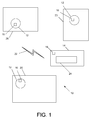
- FIG. 1 depicts a functional block diagram of an intrusion warning and reporting network 10 according to one embodiment of the system.
- Intrusion warning and reporting network 10 includes one or more sensors 12 and a controller 14. Each of the one or more sensors 12 is equipped with a sensor radio 16. Controller 14 is equipped with a controller radio 18. Each sensor of the one or more sensors 12 is placed within a monitor area 20 and communicates with controller 14 via a radio network 22. Controller 14 may comprise a display 24.
- a user will associate the one or more sensors 12 with controller 14 to form radio network 22.
- the user will place the sensors, either before or after being associated with controller 14, in areas where intrusion detection is desired.
- Each area where intrusion detection is desired i.e. monitor area 20, is surveilled by a sensor of the one or more sensors 12.
- the sensors of the one or more sensors 12 will preferably be disposed within communication range of controller 14.
- Controller 14 informs a user visually (via display 24), aurally, and/or haptically of the intrusion.
- Display 24 may show details about the intrusion including information regarding the time of the intrusion. Display 24 may also show information regarding the location of the intrusion. For example, details regarding the location of the intrusion may include geographic coordinates. If monitor area 20 is a building, display 24 may show details regarding location that include the building layout, and may further show the specific location of the intrusion within the building layout. Alternatively, if monitor area 20 is an outdoor area, the location information details may include a layout of the outdoor area, and further display the specific location of the intrusion within the specified outdoor area. The location details may include a map display, wherein the location of the intrusion is highlighted on the map display. If the sensor is, or includes, an imaging sensor, recorded visual images may also be transmitted to and shown on display 24.
- Radio network 22 may be configured from short-haul radios within each sensor of one or more sensors 12 and controller 14 to form a short-haul communications network. If radio network 22 is a short-haul communications network, it may operate within a range up to approximately 100 meters. As an example, radio network 22 may be a Zig Bee short-haul radio network. However, radio network 22 is not limited to a short-haul network and may comprise a long-haul network. Radio network 22 may also be a short-haul network that is in communication with a long-haul network, allowing for information regarding an intrusion to be sent from controller 14 to a remote monitoring location.
- Radio network 22 may also be an ad-hoc network.
- the ad-hoc network has a flexible architecture to accommodate different types of sensors and to allow for the communication of varying quantities of sensors with controller 14.
- Controller 14 may be implemented in accordance with any one of numerous configurations.
- controller 14 may be housed within a computer, such as a laptop or a desktop computer.
- controller 14 may be a handheld computer, such as a personal digital assistant ("PDA").
- PDA personal digital assistant
- Controller 14 may be a ruggedized PDA, (“RPDA”) which comprises a hardened case for rugged and dangerous environments.
- Controller 14 may be a wearable, wrist-mounted controller.
- a user simply attaches controller 14 to his or her wrist with straps 26, as shown in FIG. 2 . The user may then view information regarding an intrusion via wrist-mounted controller display 28.
- controller 14 may vibrate to alert a user of an intrusion.
- a vibration annunciator may be included and the controller may turn on the vibration annunciator to further alert a user that an intrusion has occurred.
- the one or more sensors 12 may be infrared motion sensors. Infrared motion sensors detect the movement of the body of a human being or animal by detecting a change of emitted infrared energy from the human or animal. Alternatively, the one or more sensors 12 may be a number of other sensors currently known in the art. Each sensor of the one or more sensors 12 may be further configured to create a noise if an intrusion is detected. A situation in which an alerting noise emanating from a sensor may be desired might be to warn an intruder of a dangerous area, such as if an intruder enters a radioactive zone, for example.
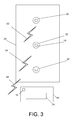
- the one or more sensors 12 may be planted in series, as shown in FIG. 3 .
- a first sensor 30 is linked in communication with a second sensor 32.
- Second sensor 32 is linked in communication with a third sensor 34.
- FIG. 3 shows only three sensors, many other number configurations of sensors may be used.
- First sensor 30 communicates over first radio network 52 with second sensor 32.
- Second sensor 32 communicates over second radio network 54 with third sensor 34, and third sensor 34 communicates over radio network 56 with controller 14. If first sensor 30 detects an intrusion, first sensor 30 may send a signal to second sensor 32, which sends the signal to third sensor 34, and third sensor 34 sends the signal to controller 14.
- controller 14 can be up to 300m away from first sensor 30 yet can still monitor the area surrounding first sensor 30. By setting up these sensors in series, the sensors may communicate with controller 14 over a larger area than any single sensor could reach.
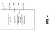
- FIG. 4 depicts various functions that may be implemented by controller 14 in the system of FIG. 1 .
- Display 24 may show a control and display screen 36.
- Control and display screen 36 may show a plurality of screen options 38. Although four screen options are depicted in FIG. 4 , control and display screen 36 is not limited to four screen options, and a number of other screen options may be present.
- a user may select one of the plurality of screen options 38 from control and display screen 36.
- the plurality of screen options 38 shown in FIG. 4 are an alerts screen 38a, an add sensor screen 38b, a command screen 38c, and a network status screen 38d. Although only these particular screen options are shown, the display is not limited to these specific options and other options may be included or substituted.
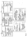
- FIG. 5 depicts various exemplary user interface screens 40 that may be displayed on display 24 of controller 14 of FIG. 4 .
- FIG. 5 shows an add sensor screen 40a, an alerts screen 40b, a command screen 40c, a network status screen 40d, and an image screen 40e.
- add sensor screen 40a, alerts screen 40b, command screen 40c, and network status screen 40d may be selected from control and display screen 36.
- Image screen 40e may be selected from alerts screen 40b.
- image screen 40e may be selected from a different
- Alerts screen 40b may show information regarding the last intrusion alert and allow a user to further select image screen 40e to view still images or either a recorded or streaming video of an intrusion. Alerts screen 40b may also show or provide access to any of the location information of an intrusion previously discussed.
- Add sensor screen 40a allows a user to add more sensors to the network.
- Command screen 40c allows a user to change the status of a sensor; a sensor could be set to a number of different modes. For example, the sensor could be either active or inactive, depending on whether that particular area within which the sensor is placed requires surveillance.
- Network status screen 40d may provide a user with information regarding the mode set for each sensor, amount of battery remaining in each sensor, as well as the type of sensor.
Abstract
Description
- The present patent application claims priority under 35 U.S.C. § 119(e) to
U.S. Provisional Patent Application Serial No. 60/878,778 , which was filed January 4, 2007. The full disclosure ofU.S. Provisional Patent Application Serial No. 60/878,778 is incorporated herein by reference. - The present invention relates generally to intrusion detection and warning. More particularly, the present invention relates to a network-based intrusion warning and reporting system and method.
- Security systems are typically deployed in homes and commercial buildings to prevent theft, damage, and injury to persons within the buildings. These systems typically include various alarm components which communicate to a central controller. Once one of these alarm components, such as a sensor, detects an intrusion, a transmitter associated with the sensor transmits signals to the central controller. The central controller then alerts a user that an intrusion has occurred. The central controller may alert a user of an intrusion via the user's cell phone. The central controller traditionally alerts a user by either a vibration, a repeating noise, or a simple visual, such as a flashing light.
- However, the surveillance networks currently available do not provide the information desired for applications such as a hostile military environment. In a military application, it is not sufficient to merely be alerted of an intrusion into an area under surveillance, a user also needs to know location information of the intrusion. With location information, the intruder can be properly tracked and caught, if necessary. This location information is desirable and beneficial for other applications as well, such as home security, industrial security, and the protection of penitentiaries.
- It is highly desirable to provide a new and improved network for providing remote supervision of intrusions. It is thus highly desirable to provide a new and improved communication network between a plurality of sensors at different locations and a controller, where the network utilizes a plurality of sensory displays, signals and prompts to supervise and report intrusions and intrusion information at spaced remote locations.
- The present invention overcomes many of the disadvantages of the prior art by providing an intrusion warning and reporting network designed to detect intrusions in the area, to inform users monitoring the area when an intrusion has occurred, and to inform the users of the location of the intrusion.
- The intrusion detection and reporting network includes one or more sensors and a remote controller. A user will associate the sensors with the controller to form a radio network. The user will place the sensors, either before or after being associated with the controller, in areas where intrusion detection is desired.
- When a sensor detects an intrusion, an appropriate signal is transmitted to the controller via the radio network. A display associated with the controller allows the user to view details concerning the intrusion. These details may include information regarding the time and location of the intrusion, and they may be communicated visually, aurally, and/or haptically.
- The display may be an interactive display, where the user can select screen options from an initial screen. The screen options may be, for example, an alert screen, an add sensor screen, a command screen, or a network status screen. The alert screen may show information regarding the last alert and allow the user to further select an image screen to view images of an intrusion. The add sensor screen allows the user to add more sensors to the network. The command screen allows the user to change the status of a sensor; a sensor could be set to a number of different modes. For example, the sensor could be either active or inactive, depending on whether the particular area within which the sensor is placed requires surveillance. A network status screen may provide the user with information regarding the mode set for each sensor, the amount of battery remaining in each sensor, as well as the type of sensor. If the sensor is, or includes, an imaging sensor, recorded visual images may be transmitted to and shown on the display. In addition, the controller may inform the user of an intrusion with any one of numerous types of annunciators, such as a vibration annunciator.
- The controller may be housed within a computer, such as a laptop or desktop computer. The controller may also be housed within a personal digital assistant, or a wrist-mountable device.
- The intrusion detection and reporting network may have many practical applications. For example, the intrusion detection and reporting network can be applied to military, home, industrial, corporate, neighborhood, or penitentiary use.
- Various embodiments are described herein with reference to the following drawings. Certain aspects of the drawings are depicted in a simplified way for reason of clarity. Not all alternatives and options are shown in the drawings and, therefore, the invention is not limited in scope to the content of the drawings. In the drawings:
-
Figure 1 is a functional block diagram of an intrusion detection and reporting system according to one embodiment of the present invention; -
Figure 2 depicts an embodiment of a wrist-mountable controller; -
Figure 3 depicts an embodiment ofFIG. 1 wherein sensors of the intrusion detection and reporting system are planted in series; -
Figure 4 depicts various functions that may be implemented by a controller in the system ofFIG. 1 ; and -
Figure 5 depicts various user interface screens that may be displayed on a display screen of the controller ofFIG. 4 . -
FIG. 1 depicts a functional block diagram of an intrusion warning and reportingnetwork 10 according to one embodiment of the system. Intrusion warning andreporting network 10 includes one ormore sensors 12 and acontroller 14. Each of the one ormore sensors 12 is equipped with asensor radio 16.Controller 14 is equipped with acontroller radio 18. Each sensor of the one ormore sensors 12 is placed within amonitor area 20 and communicates withcontroller 14 via aradio network 22.Controller 14 may comprise adisplay 24. - In operation, a user will associate the one or
more sensors 12 withcontroller 14 to formradio network 22. The user will place the sensors, either before or after being associated withcontroller 14, in areas where intrusion detection is desired. Each area where intrusion detection is desired,i.e. monitor area 20, is surveilled by a sensor of the one ormore sensors 12. The sensors of the one ormore sensors 12 will preferably be disposed within communication range ofcontroller 14. When one of the one ormore sensors 12 detects an intrusion, that sensor transmits an appropriate signal to controller 14 viaradio network 22.Controller 14, in turn, informs a user visually (via display 24), aurally, and/or haptically of the intrusion. -
Display 24 may show details about the intrusion including information regarding the time of the intrusion.Display 24 may also show information regarding the location of the intrusion. For example, details regarding the location of the intrusion may include geographic coordinates. Ifmonitor area 20 is a building,display 24 may show details regarding location that include the building layout, and may further show the specific location of the intrusion within the building layout. Alternatively, ifmonitor area 20 is an outdoor area, the location information details may include a layout of the outdoor area, and further display the specific location of the intrusion within the specified outdoor area. The location details may include a map display, wherein the location of the intrusion is highlighted on the map display. If the sensor is, or includes, an imaging sensor, recorded visual images may also be transmitted to and shown ondisplay 24. -
Radio network 22 may be configured from short-haul radios within each sensor of one ormore sensors 12 andcontroller 14 to form a short-haul communications network. Ifradio network 22 is a short-haul communications network, it may operate within a range up to approximately 100 meters. As an example,radio network 22 may be a Zig Bee short-haul radio network. However,radio network 22 is not limited to a short-haul network and may comprise a long-haul network.Radio network 22 may also be a short-haul network that is in communication with a long-haul network, allowing for information regarding an intrusion to be sent fromcontroller 14 to a remote monitoring location. -
Radio network 22 may also be an ad-hoc network. The ad-hoc network has a flexible architecture to accommodate different types of sensors and to allow for the communication of varying quantities of sensors withcontroller 14. -
Controller 14 may be implemented in accordance with any one of numerous configurations. In one embodiment,controller 14 may be housed within a computer, such as a laptop or a desktop computer. Alternatively,controller 14 may be a handheld computer, such as a personal digital assistant ("PDA").Controller 14 may be a ruggedized PDA, ("RPDA") which comprises a hardened case for rugged and dangerous environments.Controller 14 may be a wearable, wrist-mounted controller. In this embodiment, a user simply attachescontroller 14 to his or her wrist withstraps 26, as shown inFIG. 2 . The user may then view information regarding an intrusion via wrist-mountedcontroller display 28. - In addition to providing location information,
controller 14 may vibrate to alert a user of an intrusion. In this embodiment, a vibration annunciator may be included and the controller may turn on the vibration annunciator to further alert a user that an intrusion has occurred. - The one or
more sensors 12 may be infrared motion sensors. Infrared motion sensors detect the movement of the body of a human being or animal by detecting a change of emitted infrared energy from the human or animal. Alternatively, the one ormore sensors 12 may be a number of other sensors currently known in the art. Each sensor of the one ormore sensors 12 may be further configured to create a noise if an intrusion is detected. A situation in which an alerting noise emanating from a sensor may be desired might be to warn an intruder of a dangerous area, such as if an intruder enters a radioactive zone, for example. - The one or
more sensors 12 may be planted in series, as shown inFIG. 3 . In this embodiment, afirst sensor 30 is linked in communication with asecond sensor 32.Second sensor 32 is linked in communication with athird sensor 34. AlthoughFIG. 3 shows only three sensors, many other number configurations of sensors may be used. -
First sensor 30 communicates overfirst radio network 52 withsecond sensor 32.Second sensor 32 communicates oversecond radio network 54 withthird sensor 34, andthird sensor 34 communicates overradio network 56 withcontroller 14. Iffirst sensor 30 detects an intrusion,first sensor 30 may send a signal tosecond sensor 32, which sends the signal tothird sensor 34, andthird sensor 34 sends the signal tocontroller 14. Thus in this embodiment,controller 14 can be up to 300m away fromfirst sensor 30 yet can still monitor the area surroundingfirst sensor 30. By setting up these sensors in series, the sensors may communicate withcontroller 14 over a larger area than any single sensor could reach. -
FIG. 4 depicts various functions that may be implemented bycontroller 14 in the system ofFIG. 1 .Display 24 may show a control anddisplay screen 36. Control anddisplay screen 36 may show a plurality of screen options 38. Although four screen options are depicted inFIG. 4 , control anddisplay screen 36 is not limited to four screen options, and a number of other screen options may be present. A user may select one of the plurality of screen options 38 from control anddisplay screen 36. The plurality of screen options 38 shown inFIG. 4 are analerts screen 38a, anadd sensor screen 38b, acommand screen 38c, and anetwork status screen 38d. Although only these particular screen options are shown, the display is not limited to these specific options and other options may be included or substituted. - Once a user selects a screen option, a user interface screen 40 will appear on
display 24.FIG. 5 depicts various exemplary user interface screens 40 that may be displayed ondisplay 24 ofcontroller 14 ofFIG. 4 .FIG. 5 shows anadd sensor screen 40a, analerts screen 40b, acommand screen 40c, anetwork status screen 40d, and animage screen 40e. As previously described, addsensor screen 40a, alertsscreen 40b,command screen 40c, andnetwork status screen 40d may be selected from control anddisplay screen 36.Image screen 40e may be selected fromalerts screen 40b. Alternatively,image screen 40e may be selected from a different - Alerts screen 40b may show information regarding the last intrusion alert and allow a user to further select
image screen 40e to view still images or either a recorded or streaming video of an intrusion. Alerts screen 40b may also show or provide access to any of the location information of an intrusion previously discussed. - Add
sensor screen 40a allows a user to add more sensors to the network. -
Command screen 40c allows a user to change the status of a sensor; a sensor could be set to a number of different modes. For example, the sensor could be either active or inactive, depending on whether that particular area within which the sensor is placed requires surveillance. -
Network status screen 40d may provide a user with information regarding the mode set for each sensor, amount of battery remaining in each sensor, as well as the type of sensor. - Although the invention has been described in detail with particular reference to a preferred embodiment, other embodiments can achieve the same results. Variations and modifications of the present invention will be obvious to those skilled in the art and it is intended to cover in the appended claims all such modifications and equivalents. The entire disclosures of all references, applications, patents, and publications cited above, are hereby incorporated by reference.
Claims (10)
- An intrusion detection and reporting system comprising:at least one sensor for detecting an intrusion; anda controller in communication with the at least one sensor via a radio network,wherein the controller comprises a display,
wherein in response to detection of an intrusion, the at least one sensor transmits time information and location information regarding the intrusion via the radio network to the controller, and the display shows the time information and location information to a user. - The system as in claim 1, wherein the at least one sensor captures an image of the intrusion and transmits the image of the intrusion to the controller.
- The system as in claim 1, wherein the location information includes geographic coordinates of a location of the intrusion.
- The system as in claim 1, further comprising an annunciator, wherein the annunciator comprises a radio which is in communication with the controller, and in response to receiving a signal from the controller over the radio the annunciator vibrates to alert the user of an intrusion.
- The system as in claim 4, wherein the controller communicates with the annunciator via a wireless communication link.
- The system as in claim 1, wherein the controller is housed in a wrist-mountable device.
- The system as in claim 1, wherein information regarding the intrusion is transmitted from the controller to a remote monitoring location using a long-haul radio.
- The system as in claim 1, wherein the at least one sensor and the controller are compatible with at least one of: cellular protocol, Bluetooth protocol, Zig Bee protocol.
- An intrusion detection and reporting network comprising:at least one sensor; anda wireless wearable controller adapted to communicate with the at least one sensor,wherein the wireless controller comprises a display screen;
wherein the at least once sensor detects and wirelessly transmits intrusion information, comprising time information and location information of the intrusion, to the controller, and in response to the report, a user may view the intrusion information on the display screen. - A method for detecting and reporting an intrusion, comprising:placing at least one sensor in an monitor area;detecting an intrusion in the monitor area with the at least one sensor;transmitting time information and location information about the intrusion from the at least one sensor to a controller via a wireless radio network;displaying time information and location information concerning the intrusion to a user via a controller display.
Applications Claiming Priority (2)
| Application Number | Priority Date | Filing Date | Title |
|---|---|---|---|
| US87877807P | 2007-01-04 | 2007-01-04 | |
| US11/968,812 US20100283608A1 (en) | 2007-01-04 | 2008-01-03 | Intrusion Warning and Reporting Network |
Publications (2)
| Publication Number | Publication Date |
|---|---|
| EP1965362A2 true EP1965362A2 (en) | 2008-09-03 |
| EP1965362A3 EP1965362A3 (en) | 2010-05-05 |
Family
ID=39629010
Family Applications (1)
| Application Number | Title | Priority Date | Filing Date |
|---|---|---|---|
| EP08100129A Withdrawn EP1965362A3 (en) | 2007-01-04 | 2008-01-04 | Intrusion warning and reporting network |
Country Status (3)
| Country | Link |
|---|---|
| US (1) | US20100283608A1 (en) |
| EP (1) | EP1965362A3 (en) |
| JP (1) | JP2008293471A (en) |
Families Citing this family (7)
| Publication number | Priority date | Publication date | Assignee | Title |
|---|---|---|---|---|
| US8855554B2 (en) * | 2008-03-05 | 2014-10-07 | Qualcomm Incorporated | Packaging and details of a wireless power device |
| US8497658B2 (en) | 2009-01-22 | 2013-07-30 | Qualcomm Incorporated | Adaptive power control for wireless charging of devices |
| US8410941B2 (en) | 2010-03-08 | 2013-04-02 | Leviathink Laboratories Llc | Animal detection system and method |
| JP2011193063A (en) * | 2010-03-12 | 2011-09-29 | Sanyo Electric Co Ltd | Electronic camera |
| US9646480B2 (en) * | 2013-10-07 | 2017-05-09 | Google Inc. | Smart home device with integrated conditional lighting |
| WO2017115145A1 (en) | 2015-12-31 | 2017-07-06 | Delta Faucet Company | Water sensor |
| CN110149324B (en) * | 2019-05-13 | 2020-02-14 | 特斯联(北京)科技有限公司 | Network attack prevention method, device and equipment |
Citations (3)
| Publication number | Priority date | Publication date | Assignee | Title |
|---|---|---|---|---|
| GB2381363A (en) | 2001-10-25 | 2003-04-30 | Paul Clarke | Distance monitoring alarm and locating device |
| US20060181413A1 (en) | 2005-01-28 | 2006-08-17 | Systems Microtechnologies, Inc. | Transportation security system and associated methods |
| US20060220843A1 (en) | 2005-03-30 | 2006-10-05 | Alan Broad | Interactive surveillance network and method |
Family Cites Families (55)
| Publication number | Priority date | Publication date | Assignee | Title |
|---|---|---|---|---|
| US2345771A (en) * | 1941-10-21 | 1944-04-04 | Du Pont | Alarm system |
| US3109165A (en) * | 1958-09-05 | 1963-10-29 | Specialties Dev Corp | Intruder detecting system |
| US3745552A (en) * | 1971-09-13 | 1973-07-10 | Teledyne Ind | Intrusion signature detector requiring both frequency and amplitude shifts |
| US3974489A (en) * | 1972-08-30 | 1976-08-10 | Bleeker George H | Centralized monitor and alarm system for monitoring remote areas with acoustical electric transducers |
| US3913085A (en) * | 1974-01-16 | 1975-10-14 | Westinghouse Electric Corp | Multichannel system for seismic signature determination |
| US4374378A (en) * | 1981-01-28 | 1983-02-15 | The United States Of America As Represented By The United States National Aeronautics And Space Administration | Scanning seismic intrusion detection method and apparatus |
| US4602357A (en) * | 1982-02-12 | 1986-07-22 | Ensco Inc. | Coded acoustic alarm transmitter/receiver system |
| US4523185A (en) * | 1982-03-15 | 1985-06-11 | Albert Roth | Zoned intrusion display with series-connected sensors |
| US4468763A (en) * | 1983-05-06 | 1984-08-28 | Honeywell Inc. | Seismic intruder detection using pressure waves |
| US4591834A (en) * | 1983-11-25 | 1986-05-27 | Argus Systems, Inc. | Intrusion detecting apparatus with zone identification and with noise interference discrimination |
| DE3617847C1 (en) * | 1986-05-27 | 1987-02-26 | Wasagchemie Sythen Gmbh | Ground listening device with at least one three-component geophone probe |
| US4742336A (en) * | 1986-12-04 | 1988-05-03 | Hall Security Services, Inc. | Portable intrusion detection warning system |
| US4897630A (en) * | 1987-01-21 | 1990-01-30 | Electronic Security Products Of California, Inc. | Programmable alarm system having proximity detection with vocal alarm and reporting features |
| GB2213333B (en) * | 1987-12-02 | 1992-02-26 | Morris Maram | Detector units |
| US4833449A (en) * | 1988-07-05 | 1989-05-23 | Gaffigan Robert J | Home security system |
| US4857912A (en) * | 1988-07-27 | 1989-08-15 | The United States Of America As Represented By The Secretary Of The Navy | Intelligent security assessment system |
| US5559496A (en) * | 1993-05-19 | 1996-09-24 | Dubats; William C. | Remote patrol system |
| US5920270A (en) * | 1994-07-22 | 1999-07-06 | Digital Security Controls Ltd. | Security system remote control |
| US5638046A (en) * | 1995-02-13 | 1997-06-10 | Malinowski; Robert | Security system |
| US5570079A (en) * | 1995-04-24 | 1996-10-29 | Dockery; Devan | Home security system for detecting an intrusion into a monitored area by an infrared detector |
| GB9512753D0 (en) * | 1995-06-22 | 1995-08-30 | Dando David J | Intrusion sensing system |
| US5821855A (en) * | 1997-02-28 | 1998-10-13 | Lewis; Tommy J. | Recognition responsive security system |
| US5852402A (en) * | 1997-10-28 | 1998-12-22 | Safeguards Technology, Inc. | Intrusion detection system |
| US6204760B1 (en) * | 1998-01-30 | 2001-03-20 | Interactive Technologies, Inc. | Security system for a building complex having multiple units |
| US5969608A (en) * | 1998-02-23 | 1999-10-19 | The United States Of America As Represented By The Secretary Of The Navy | Magneto-inductive seismic fence |
| US20040105533A1 (en) * | 1998-08-07 | 2004-06-03 | Input/Output, Inc. | Single station wireless seismic data acquisition method and apparatus |
| US6255936B1 (en) * | 1999-04-07 | 2001-07-03 | Joe Amato | Beeper security system |
| US6177903B1 (en) * | 1999-06-14 | 2001-01-23 | Time Domain Corporation | System and method for intrusion detection using a time domain radar array |
| US6917288B2 (en) * | 1999-09-01 | 2005-07-12 | Nettalon Security Systems, Inc. | Method and apparatus for remotely monitoring a site |
| US6536553B1 (en) * | 2000-04-25 | 2003-03-25 | The United States Of America As Represented By The Secretary Of The Army | Method and apparatus using acoustic sensor for sub-surface object detection and visualization |
| JP3843733B2 (en) * | 2000-11-27 | 2006-11-08 | 松下電工株式会社 | Security monitoring system using communication network |
| US20020080567A1 (en) * | 2000-12-21 | 2002-06-27 | Martin Bone | Hard case for handheld computer system |
| JP2002216578A (en) * | 2001-01-17 | 2002-08-02 | Maruyasu Industries Co Ltd | Mat radio switch system, mat radio switch and receiver |
| US6995664B1 (en) * | 2001-06-20 | 2006-02-07 | Jeffrey Darling | Remote supervision system and method |
| US6703930B2 (en) * | 2001-10-05 | 2004-03-09 | Hewlett-Packard Development Company, L.P. | Personal alerting apparatus and methods |
| AUPS157702A0 (en) * | 2002-04-05 | 2002-05-16 | King, Quentin | System for providing tactile stimulation |
| US6734790B1 (en) * | 2002-05-01 | 2004-05-11 | Scotty Hodger | Security alarm wrist watch |
| US7161479B2 (en) * | 2002-08-12 | 2007-01-09 | Sobol Raymond J | Portable instantaneous wireless even based photo identification and alerting security system |
| US7589626B2 (en) * | 2002-09-23 | 2009-09-15 | Xanadoo Company | Security system and method |
| IL152310A (en) * | 2002-10-15 | 2010-05-17 | Magal Security Systems Ltd | System and method for detecting, locating and recognizing an approach toward an elongated installation |
| US6917309B2 (en) * | 2002-10-28 | 2005-07-12 | Integritech System Engineering Ltd. | Foreign object detection system and method |
| US7019641B1 (en) * | 2003-03-13 | 2006-03-28 | M-Vision Inc. | Human being presence detection system |
| JPWO2004086328A1 (en) * | 2003-03-25 | 2006-06-29 | 笹倉 豊喜 | Home security system |
| JP4068494B2 (en) * | 2003-04-08 | 2008-03-26 | アルパイン株式会社 | Communication data relay method and inter-vehicle communication system |
| US20050237187A1 (en) * | 2004-04-09 | 2005-10-27 | Martin Sharon A H | Real-time security alert & connectivity system for real-time capable wireless cellphones and palm/hand-held wireless apparatus |
| JP2005322115A (en) * | 2004-05-11 | 2005-11-17 | Matsushita Electric Ind Co Ltd | Notification system, information processing method, and program |
| JP2006000999A (en) * | 2004-06-21 | 2006-01-05 | Nec Fielding Ltd | Monitoring system, its method, monitoring robot and program |
| US7173525B2 (en) * | 2004-07-23 | 2007-02-06 | Innovalarm Corporation | Enhanced fire, safety, security and health monitoring and alarm response method, system and device |
| US7148797B2 (en) * | 2004-07-23 | 2006-12-12 | Innovalarm Corporation | Enhanced fire, safety, security and health monitoring and alarm response method, system and device |
| US20070236343A1 (en) * | 2004-09-23 | 2007-10-11 | Becksted Albert M | Surveillance network for unattended ground sensors |
| US7234897B2 (en) * | 2004-12-27 | 2007-06-26 | Vincent Paul Conroy | Area earthquake defense system |
| US7321303B2 (en) * | 2005-10-05 | 2008-01-22 | Hsin Chen | Remote surveillance device |
| JP2007241933A (en) * | 2006-03-13 | 2007-09-20 | Matsushita Electric Ind Co Ltd | Monitoring system, control method, and program thereof |
| US7701331B2 (en) * | 2006-06-12 | 2010-04-20 | Tran Bao Q | Mesh network door lock |
| US8154398B2 (en) * | 2007-10-23 | 2012-04-10 | La Crosse Technology | Remote location monitoring |
-
2008
- 2008-01-03 US US11/968,812 patent/US20100283608A1/en not_active Abandoned
- 2008-01-04 JP JP2008000155A patent/JP2008293471A/en active Pending
- 2008-01-04 EP EP08100129A patent/EP1965362A3/en not_active Withdrawn
Patent Citations (3)
| Publication number | Priority date | Publication date | Assignee | Title |
|---|---|---|---|---|
| GB2381363A (en) | 2001-10-25 | 2003-04-30 | Paul Clarke | Distance monitoring alarm and locating device |
| US20060181413A1 (en) | 2005-01-28 | 2006-08-17 | Systems Microtechnologies, Inc. | Transportation security system and associated methods |
| US20060220843A1 (en) | 2005-03-30 | 2006-10-05 | Alan Broad | Interactive surveillance network and method |
Also Published As
| Publication number | Publication date |
|---|---|
| EP1965362A3 (en) | 2010-05-05 |
| JP2008293471A (en) | 2008-12-04 |
| US20100283608A1 (en) | 2010-11-11 |
Similar Documents
| Publication | Publication Date | Title |
|---|---|---|
| EP2325822B1 (en) | Alert system with zoning using wireless portable detectors and a central station | |
| EP1965362A2 (en) | Intrusion warning and reporting network | |
| CA2684905C (en) | Methods for emergency communication within a fire safety system | |
| EP3033742B1 (en) | System and method for video/audio and event dispatch using positioning system | |
| AU2010271080B2 (en) | Video surveillance system | |
| US20020057365A1 (en) | Monitoring or security device and methods | |
| US20060214785A1 (en) | Distributed multi-nodal voice/data communication | |
| CA2989010C (en) | Systems, methods and techniques for device pairing via a short-range pairing mechanism | |
| EP3314589B1 (en) | An alert system and method | |
| CA2684900A1 (en) | Mobile emergency device for emergency personnel | |
| KR20080101609A (en) | System, apparatus and method for keeping a person under surveillance | |
| US20120127983A1 (en) | Electronic device and method for transmitting warning information, and security monitoring system | |
| KR101480302B1 (en) | A system for preventing crimes in vulnerable areas by interworking with smart watches and the method thereof | |
| US9449479B2 (en) | Security system | |
| US20120262289A1 (en) | Security systems having portable monitoring devices and methods using same | |
| EP2463839A1 (en) | Multi-functional wireless equipment for monitoring and protection of person, mode of operation of the equipment | |
| KR101266814B1 (en) | System for emergency rescue | |
| US9921290B2 (en) | System and method for situational awareness | |
| US7042355B2 (en) | Environmental cameras | |
| JP2000500638A (en) | Video surveillance system and method | |
| US7898408B2 (en) | Voice-aided unattended surveillance sensor deployment system and associated methods | |
| JP2019096276A (en) | Watching system | |
| WO2023127169A1 (en) | Surveillance system and surveillance program | |
| JP2005316735A (en) | Wanderer informing system and portable terminal | |
| JP2008277997A (en) | Crime prevention device, monitor device, and crime prevention system |
Legal Events
| Date | Code | Title | Description |
|---|---|---|---|
| PUAI | Public reference made under article 153(3) epc to a published international application that has entered the european phase |
Free format text: ORIGINAL CODE: 0009012 |
|
| 17P | Request for examination filed |
Effective date: 20080104 |
|
| AK | Designated contracting states |
Kind code of ref document: A2 Designated state(s): AT BE BG CH CY CZ DE DK EE ES FI FR GB GR HR HU IE IS IT LI LT LU LV MC MT NL NO PL PT RO SE SI SK TR |
|
| AX | Request for extension of the european patent |
Extension state: AL BA MK RS |
|
| PUAL | Search report despatched |
Free format text: ORIGINAL CODE: 0009013 |
|
| AK | Designated contracting states |
Kind code of ref document: A3 Designated state(s): AT BE BG CH CY CZ DE DK EE ES FI FR GB GR HR HU IE IS IT LI LT LU LV MC MT NL NO PL PT RO SE SI SK TR |
|
| AX | Request for extension of the european patent |
Extension state: AL BA MK RS |
|
| 17Q | First examination report despatched |
Effective date: 20100421 |
|
| AKX | Designation fees paid |
Designated state(s): DE FR GB |
|
| STAA | Information on the status of an ep patent application or granted ep patent |
Free format text: STATUS: THE APPLICATION IS DEEMED TO BE WITHDRAWN |
|
| 18D | Application deemed to be withdrawn |
Effective date: 20130801 |