EP1961838A1 - Method and apparatus for comtrolling gas flow to a processing chamber - Google Patents
Method and apparatus for comtrolling gas flow to a processing chamber Download PDFInfo
- Publication number
- EP1961838A1 EP1961838A1 EP20080151408 EP08151408A EP1961838A1 EP 1961838 A1 EP1961838 A1 EP 1961838A1 EP 20080151408 EP20080151408 EP 20080151408 EP 08151408 A EP08151408 A EP 08151408A EP 1961838 A1 EP1961838 A1 EP 1961838A1
- Authority
- EP
- European Patent Office
- Prior art keywords
- gas
- manifold
- gases
- flow
- processing chamber
- Prior art date
- Legal status (The legal status is an assumption and is not a legal conclusion. Google has not performed a legal analysis and makes no representation as to the accuracy of the status listed.)
- Withdrawn
Links
- 238000012545 processing Methods 0.000 title claims abstract description 113
- 238000000034 method Methods 0.000 title claims abstract description 45
- 239000007789 gas Substances 0.000 claims abstract description 266
- 239000000758 substrate Substances 0.000 claims abstract description 17
- 238000010926 purge Methods 0.000 claims description 37
- 239000000203 mixture Substances 0.000 claims description 11
- 230000008859 change Effects 0.000 claims description 8
- 230000004044 response Effects 0.000 claims description 8
- 239000004065 semiconductor Substances 0.000 abstract description 12
- 239000000126 substance Substances 0.000 description 22
- 230000008569 process Effects 0.000 description 18
- 238000002156 mixing Methods 0.000 description 12
- 230000008878 coupling Effects 0.000 description 7
- 238000010168 coupling process Methods 0.000 description 7
- 238000005859 coupling reaction Methods 0.000 description 7
- 230000001276 controlling effect Effects 0.000 description 5
- 238000002955 isolation Methods 0.000 description 5
- 238000010586 diagram Methods 0.000 description 4
- 238000012795 verification Methods 0.000 description 4
- 230000001105 regulatory effect Effects 0.000 description 3
- 238000013459 approach Methods 0.000 description 2
- 238000005229 chemical vapour deposition Methods 0.000 description 2
- 230000002708 enhancing effect Effects 0.000 description 2
- 238000005530 etching Methods 0.000 description 2
- 238000005240 physical vapour deposition Methods 0.000 description 2
- 238000012163 sequencing technique Methods 0.000 description 2
- 238000003860 storage Methods 0.000 description 2
- 239000002699 waste material Substances 0.000 description 2
- 238000004458 analytical method Methods 0.000 description 1
- 238000004380 ashing Methods 0.000 description 1
- XIWFQDBQMCDYJT-UHFFFAOYSA-M benzyl-dimethyl-tridecylazanium;chloride Chemical compound [Cl-].CCCCCCCCCCCCC[N+](C)(C)CC1=CC=CC=C1 XIWFQDBQMCDYJT-UHFFFAOYSA-M 0.000 description 1
- 230000033228 biological regulation Effects 0.000 description 1
- 238000004891 communication Methods 0.000 description 1
- 238000001816 cooling Methods 0.000 description 1
- 230000007547 defect Effects 0.000 description 1
- 238000007872 degassing Methods 0.000 description 1
- 238000000151 deposition Methods 0.000 description 1
- 230000008021 deposition Effects 0.000 description 1
- 230000003292 diminished effect Effects 0.000 description 1
- 230000000694 effects Effects 0.000 description 1
- 238000005516 engineering process Methods 0.000 description 1
- 230000007613 environmental effect Effects 0.000 description 1
- 239000012530 fluid Substances 0.000 description 1
- 239000007943 implant Substances 0.000 description 1
- 150000002500 ions Chemical class 0.000 description 1
- 238000004519 manufacturing process Methods 0.000 description 1
- 230000013011 mating Effects 0.000 description 1
- 238000005259 measurement Methods 0.000 description 1
- 238000004377 microelectronic Methods 0.000 description 1
- 238000012544 monitoring process Methods 0.000 description 1
- 238000004886 process control Methods 0.000 description 1
- 238000005086 pumping Methods 0.000 description 1
- 238000005067 remediation Methods 0.000 description 1
- 230000000717 retained effect Effects 0.000 description 1
- 230000006641 stabilisation Effects 0.000 description 1
- 238000011105 stabilization Methods 0.000 description 1
- 238000012546 transfer Methods 0.000 description 1
- 238000011144 upstream manufacturing Methods 0.000 description 1
Images


Classifications
-
- C—CHEMISTRY; METALLURGY
- C23—COATING METALLIC MATERIAL; COATING MATERIAL WITH METALLIC MATERIAL; CHEMICAL SURFACE TREATMENT; DIFFUSION TREATMENT OF METALLIC MATERIAL; COATING BY VACUUM EVAPORATION, BY SPUTTERING, BY ION IMPLANTATION OR BY CHEMICAL VAPOUR DEPOSITION, IN GENERAL; INHIBITING CORROSION OF METALLIC MATERIAL OR INCRUSTATION IN GENERAL
- C23C—COATING METALLIC MATERIAL; COATING MATERIAL WITH METALLIC MATERIAL; SURFACE TREATMENT OF METALLIC MATERIAL BY DIFFUSION INTO THE SURFACE, BY CHEMICAL CONVERSION OR SUBSTITUTION; COATING BY VACUUM EVAPORATION, BY SPUTTERING, BY ION IMPLANTATION OR BY CHEMICAL VAPOUR DEPOSITION, IN GENERAL
- C23C16/00—Chemical coating by decomposition of gaseous compounds, without leaving reaction products of surface material in the coating, i.e. chemical vapour deposition [CVD] processes
- C23C16/44—Chemical coating by decomposition of gaseous compounds, without leaving reaction products of surface material in the coating, i.e. chemical vapour deposition [CVD] processes characterised by the method of coating
- C23C16/52—Controlling or regulating the coating process
-
- H—ELECTRICITY
- H01—ELECTRIC ELEMENTS
- H01L—SEMICONDUCTOR DEVICES NOT COVERED BY CLASS H10
- H01L21/00—Processes or apparatus adapted for the manufacture or treatment of semiconductor or solid state devices or of parts thereof
- H01L21/02—Manufacture or treatment of semiconductor devices or of parts thereof
-
- C—CHEMISTRY; METALLURGY
- C23—COATING METALLIC MATERIAL; COATING MATERIAL WITH METALLIC MATERIAL; CHEMICAL SURFACE TREATMENT; DIFFUSION TREATMENT OF METALLIC MATERIAL; COATING BY VACUUM EVAPORATION, BY SPUTTERING, BY ION IMPLANTATION OR BY CHEMICAL VAPOUR DEPOSITION, IN GENERAL; INHIBITING CORROSION OF METALLIC MATERIAL OR INCRUSTATION IN GENERAL
- C23C—COATING METALLIC MATERIAL; COATING MATERIAL WITH METALLIC MATERIAL; SURFACE TREATMENT OF METALLIC MATERIAL BY DIFFUSION INTO THE SURFACE, BY CHEMICAL CONVERSION OR SUBSTITUTION; COATING BY VACUUM EVAPORATION, BY SPUTTERING, BY ION IMPLANTATION OR BY CHEMICAL VAPOUR DEPOSITION, IN GENERAL
- C23C16/00—Chemical coating by decomposition of gaseous compounds, without leaving reaction products of surface material in the coating, i.e. chemical vapour deposition [CVD] processes
- C23C16/44—Chemical coating by decomposition of gaseous compounds, without leaving reaction products of surface material in the coating, i.e. chemical vapour deposition [CVD] processes characterised by the method of coating
- C23C16/4412—Details relating to the exhausts, e.g. pumps, filters, scrubbers, particle traps
-
- C—CHEMISTRY; METALLURGY
- C23—COATING METALLIC MATERIAL; COATING MATERIAL WITH METALLIC MATERIAL; CHEMICAL SURFACE TREATMENT; DIFFUSION TREATMENT OF METALLIC MATERIAL; COATING BY VACUUM EVAPORATION, BY SPUTTERING, BY ION IMPLANTATION OR BY CHEMICAL VAPOUR DEPOSITION, IN GENERAL; INHIBITING CORROSION OF METALLIC MATERIAL OR INCRUSTATION IN GENERAL
- C23C—COATING METALLIC MATERIAL; COATING MATERIAL WITH METALLIC MATERIAL; SURFACE TREATMENT OF METALLIC MATERIAL BY DIFFUSION INTO THE SURFACE, BY CHEMICAL CONVERSION OR SUBSTITUTION; COATING BY VACUUM EVAPORATION, BY SPUTTERING, BY ION IMPLANTATION OR BY CHEMICAL VAPOUR DEPOSITION, IN GENERAL
- C23C16/00—Chemical coating by decomposition of gaseous compounds, without leaving reaction products of surface material in the coating, i.e. chemical vapour deposition [CVD] processes
- C23C16/44—Chemical coating by decomposition of gaseous compounds, without leaving reaction products of surface material in the coating, i.e. chemical vapour deposition [CVD] processes characterised by the method of coating
- C23C16/455—Chemical coating by decomposition of gaseous compounds, without leaving reaction products of surface material in the coating, i.e. chemical vapour deposition [CVD] processes characterised by the method of coating characterised by the method used for introducing gases into reaction chamber or for modifying gas flows in reaction chamber
-
- H—ELECTRICITY
- H01—ELECTRIC ELEMENTS
- H01L—SEMICONDUCTOR DEVICES NOT COVERED BY CLASS H10
- H01L21/00—Processes or apparatus adapted for the manufacture or treatment of semiconductor or solid state devices or of parts thereof
- H01L21/67—Apparatus specially adapted for handling semiconductor or electric solid state devices during manufacture or treatment thereof; Apparatus specially adapted for handling wafers during manufacture or treatment of semiconductor or electric solid state devices or components ; Apparatus not specifically provided for elsewhere
- H01L21/67005—Apparatus not specifically provided for elsewhere
- H01L21/67011—Apparatus for manufacture or treatment
- H01L21/67098—Apparatus for thermal treatment
- H01L21/67103—Apparatus for thermal treatment mainly by conduction
-
- H—ELECTRICITY
- H01—ELECTRIC ELEMENTS
- H01L—SEMICONDUCTOR DEVICES NOT COVERED BY CLASS H10
- H01L21/00—Processes or apparatus adapted for the manufacture or treatment of semiconductor or solid state devices or of parts thereof
- H01L21/67—Apparatus specially adapted for handling semiconductor or electric solid state devices during manufacture or treatment thereof; Apparatus specially adapted for handling wafers during manufacture or treatment of semiconductor or electric solid state devices or components ; Apparatus not specifically provided for elsewhere
- H01L21/67005—Apparatus not specifically provided for elsewhere
- H01L21/67011—Apparatus for manufacture or treatment
- H01L21/67098—Apparatus for thermal treatment
- H01L21/67109—Apparatus for thermal treatment mainly by convection
-
- H—ELECTRICITY
- H01—ELECTRIC ELEMENTS
- H01L—SEMICONDUCTOR DEVICES NOT COVERED BY CLASS H10
- H01L21/00—Processes or apparatus adapted for the manufacture or treatment of semiconductor or solid state devices or of parts thereof
- H01L21/67—Apparatus specially adapted for handling semiconductor or electric solid state devices during manufacture or treatment thereof; Apparatus specially adapted for handling wafers during manufacture or treatment of semiconductor or electric solid state devices or components ; Apparatus not specifically provided for elsewhere
- H01L21/67005—Apparatus not specifically provided for elsewhere
- H01L21/67011—Apparatus for manufacture or treatment
- H01L21/67098—Apparatus for thermal treatment
- H01L21/67115—Apparatus for thermal treatment mainly by radiation
-
- Y—GENERAL TAGGING OF NEW TECHNOLOGICAL DEVELOPMENTS; GENERAL TAGGING OF CROSS-SECTIONAL TECHNOLOGIES SPANNING OVER SEVERAL SECTIONS OF THE IPC; TECHNICAL SUBJECTS COVERED BY FORMER USPC CROSS-REFERENCE ART COLLECTIONS [XRACs] AND DIGESTS
- Y10—TECHNICAL SUBJECTS COVERED BY FORMER USPC
- Y10T—TECHNICAL SUBJECTS COVERED BY FORMER US CLASSIFICATION
- Y10T137/00—Fluid handling
- Y10T137/0318—Processes
- Y10T137/0324—With control of flow by a condition or characteristic of a fluid
-
- Y—GENERAL TAGGING OF NEW TECHNOLOGICAL DEVELOPMENTS; GENERAL TAGGING OF CROSS-SECTIONAL TECHNOLOGIES SPANNING OVER SEVERAL SECTIONS OF THE IPC; TECHNICAL SUBJECTS COVERED BY FORMER USPC CROSS-REFERENCE ART COLLECTIONS [XRACs] AND DIGESTS
- Y10—TECHNICAL SUBJECTS COVERED BY FORMER USPC
- Y10T—TECHNICAL SUBJECTS COVERED BY FORMER US CLASSIFICATION
- Y10T137/00—Fluid handling
- Y10T137/8593—Systems
- Y10T137/87249—Multiple inlet with multiple outlet
Definitions
- Embodiments of the present invention generally relate to a method and apparatus for controlling gas flow to a processing chamber.
- Accurate control of gas flows is an important process control attribute critical to many microelectronic device fabrication processes.
- Providing gas between a substrate and a substrate support in a semiconductor processing chamber is a well-known method for improving heat transfer between the substrate and the substrate support, thereby enhancing the precision of substrate temperature control and uniformity.
- precise control of process gas flows into the processing chamber are required in order to obtain desired processing results, particularly as critical dimensions and film thicknesses shrink.
- gases may be added to processing chamber effluent streams to mitigate the environmental impact of substrate processing. Good control of the gases added to the effluent stream is necessary to ensure both cost effective and proper remediation.
- MFC mass gas flow meter
- conventional gas delivery systems generally have fixed conduits for routing gases from the gas sources into the processing chamber. Thus, only a predefined combination of process gases may be delivered to the processing chamber at any time. Such fixed gas delivery routing prevents process flexibility. For example, processing chambers having fixed gas delivery routes may not be able to accommodate new or revised process recipes that require a different combination of process gases. Additionally, a processing chamber having a fixed gas delivery route designed to deliver one combination of process gases to perform a first process may not be able to perform a second process that utilizes a different combination of gases, thereby preventing the processing chamber from being utilized for other processes and causing the FAB owner to invest in addition capitol equipment. Thus, it would be desirable to devise a gas delivery system having greater flexibility.
- an apparatus for delivering gases to a semiconductor processing system includes a plurality of gas input lines each having an inlet port and a plurality of gas output lines each having an outlet port.
- a plurality of connecting lines are provided that couple a respective pairs of gas input and gas output lines. Connecting valves are arranged to control flow through the respective connecting lines.
- a plurality of mass gas flow controllers are arranged to control flow into a respective inlet port.
- a method of controlling gas flow to a processing system that includes a processing chamber coupled to a facility exhaust through a foreline is provides that includes providing a manifold having at least a first, second third and fourth inlet that may be selectively coupled to at least one of a first, second third and fourth outlet, flowing one or more gases through the manifold to a vacuum environment by-passing the processing chamber prior to processing or to a calibration circuit, and flowing the one or more gases into the processing chamber during substrate processing.
- a method of controlling gas flow to a processing system that includes a processing chamber coupled to a facility exhaust through a foreline.
- the method includes flowing a first gas from a first gas source into a manifold having at least a first outlet port, a second outlet port, a third outlet port and a fourth outlet port, flowing a second gas from a second gas source into the manifold, selecting an operational state of valves within the manifold to cause the first and second gases to exit through at least one of the second or third outlet ports while in a processing mode, flowing the first and second gases through the manifold and into the foreline by-passing the processing chamber until a predefine state of the gases within the manifold is obtained, directing the first and second gases exiting the manifold into the processing chamber after the predefine state has been obtained, and processing a substrate within the processing chamber.
- Figure 1 is a simplified schematic of a semiconductor processing chamber coupled to one embodiment of a gas delivery system of the present invention.
- Figure 2 is a schematic diagram of one embodiment of a mixing manifold of the gas delivery system of Figure 1 ;
- Figure 3 is a schematic diagram of another embodiment of a mixing manifold
- Figure 4 is a schematic diagram of one embodiment of two mixing manifolds coupled together
- Figure 5 is a simplified schematic of a semiconductor processing chamber coupled to another embodiment of a gas delivery system.
- Figure 6 is a simplified schematic of a semiconductor processing chamber coupled to another embodiment of a gas delivery system.
- FIG. 1 depicts a simplified schematic of a gas delivery system 100 utilized to supply gas to an exemplary semiconductor processing chamber 114.
- the processing chamber 114 may be configured to perform chemical vapor deposition (CVD), physical vapor deposition (PVD), etching process, ion implant, thermal processing, ashing, degassing, orientation or other vacuum processing technique.
- a controller 150 is coupled to the processing chamber 114 and gas delivery system 100 to control the operation thereof.
- the controller 150 generally includes a processor, support circuits and memory.
- the gas delivery system 100 located outside of the processing chamber 114 includes a plurality of gas sources coupled to a gas manifold 134.
- the manifold 134 includes a plurality of valves (discussed further below) which enable any combination of gas sources to be coupled to the processing chamber 114.
- the manifold 134 also is configured to allow quick evacuation and flow verification of individual system components and conduits.
- the system 100 may be configured to interface with any number of gas sources, six gas sources 102A-F are shown in the embodiment depicted in Figure 1 .
- Each gas source 102A-F is coupled to a respective manifold inlet port 104A-F.
- a shut-off valve 142 and a mass flow meter (MFC) 170 are disposed between each gas supply source 102A-F and respective manifold inlet port 104A-F to control the flow of gas from each source 102A-F entering the manifold 134.
- the manifold 134 includes a plurality of manifold outlet ports 106A-F that may be selectively coupled to any one of the gas supply sources 102A-F through the manifold inlet ports 104A-F. At least one of the outlet ports 106A-F may be coupled to a calibration circuit 144 and/or a purge line 154.
- the first gas delivery outlet port 106A is coupled to the calibration circuit 144 that is configured to accurately measure gas flow.
- the calibration circuit 144 includes an orifice 130 sized to provide a chocked flow condition.
- the orifice 130 is sized to provide a restriction that is substantially equal to that of the processing chamber 114.
- the orifice 130 creates flow conditions in the manifold 134 similar to conditions present when the gases are flowing into the processing chamber 114.
- the calibration circuit 144 may be utilized to perform flow verification of the MFC or other system components, while not requiring flow into the actual processing chamber 114.
- the orifice 130 may be determined by experimentation, empirical analysis or by other suitable method. In one embodiment, the orifice 130 may be determined by measuring the pressure downstream of the orifice 130 and adjusting the orifice size until a desired pressure is realized.
- the calibration circuit 144 includes a gas source, a diverter valve, an orifice, a regulating device and a sensing circuit.
- the regulating device is fluidly coupled between the gas source and an inlet of the diverter valve.
- the orifice is fluidly coupled to a first outlet of the diverter valve and has substantially the same flow resistance as a processing chamber.
- the sensing circuit is configured to receive the flow of gases passing through the orifice.
- the calibration circuit 144 utilizes a calibrated volume for receiving the gas flow. From properties and/or attributes measured from the gas in the calibrated volume, the flow rate and/or pressure of the gas entering the sensing circuit may be verified.
- the calibration circuit 144 utilizes a non-calibrated volume for receiving the gas flow.
- the calibration circuit 144 includes a vibrating member disposed in a calibrated volume.
- the calibration circuit 144 may include a sensor configured to detect at least one of electrical or magnetic characteristics of gases disposed in the calibrated volume.
- the calibration circuit 144 may include a tank supported by a cantilever.
- the flow leaving the calibration circuit 144 is coupled to the purge line 154 by a calibration circuit outlet line 142.
- An isolation valve 140 selectively isolates calibration circuit 144 from the purge line 154.
- the purge line 154 is coupled to a foreline 138 exiting the processing chamber 114 which runs to the facility exhaust 136.
- outlet ports 106B-E are coupled to one or more inlet ports of the processing chamber 114 to supply various process gases from the gas supply sources 102A-F.
- outlet ports 106B-E are respectively coupled to inlet ports 110A-D of the processing chamber 114.
- a plurality of final valves 116 may be respectively coupled between the manifold outlet ports 106B-E and chamber inlet ports 110A-D to serve as an on/off flow control of the gas flow into the processing chamber 114.
- the sixth port 106F is coupled to the purge line 154 through an isolation valve 172.
- the purge line 154 provides a fast evacuation path that facilitates efficient removal of the gases from the gas manifold 134 and into the facility exhaust 136.
- a throttle valve 156 may be utilized to control the flow of gases through the purge line 154 from the manifold 134.
- the fast evacuation path allows quick gas changes with minimal cross-talk between gases.
- the fast evacuation path may also be selectively coupled to the manifold outlet ports 106A-E and the calibration circuit 144.
- by-pass valves 108A-E are disposed between the manifold outlet ports 106A-E and the purge line 154.
- the by-pass valves 108A-E may be selectively operated to couple the outlet ports 106A-E to the foreline 138.
- the by-pass valve 108A may be selectively operated to direct gas exiting the manifold outlet port 106A into the purge line 154, bypassing the calibration circuit 144.
- by-pass valves 108B-E may be selectively operated to direct gas exiting the manifold outlet ports 106B-E into the purge line 154, by-passing the processing chamber 114.
- Isolation valve 172 controls the flow from the sixth port 106F of the manifold 134 into the purge line 154.
- Sensors 190 may also be provided at various locations in the gas delivery system 100 to provide a metric indicative of the gas flows and/or chemistries within the system 100.
- the metric provided by the sensors 190 may be utilized by the controller 150 to adjust the outputs of the MFC's 170 or other component of the gas delivery system 100 such that a desired composition, pressure, rate or volume of gases are provided to the chamber 114.
- the sensors 190 may be pressure sensor, chemistry sensor, flow rate sensor and the like.
- FIG. 2 is schematic diagram of one embodiment of the manifold 134 depicted in Figure 1 .
- Each manifold inlet port 104A-F is respectively coupled to an inlet gas delivery line 220A-F to facilitate transferring gases from the gas sources 102A-F into the manifold 134.
- Each manifold outlet port 106A-F is respectively coupled to an outlet gas delivery line 232A-F.
- Each of the gas delivery lines 232A-F may be selectively coupled to one or more of the inlet gas delivery lines 220A-F.
- the manifold 134 may be configured to interface with any number of inlet gas outlet gas delivery lines, six gas delivery lines 102A-F and six outlet gas delivery lines 232A-F are shown in the embodiment depicted in Figure 2 . Normally, the number of gas inlet delivery lines is commensurate with the number of gas sources.
- the inlet gas delivery lines 220A includes a plurality of connecting lines 250A-F coupling the inlet gas delivery line 220A to a respective outlet gas delivery line 232A-F.
- Connecting valves 204A-F are disposed in communication with the connecting lines 250A-F and may be operated to fluidly couple the inlet gas delivery line 220A to one or more of the outlet gas delivery lines 232A-F through the inlet gas delivery line 220A, depending on the selected operational state of the valves 204A-F.
- the connecting valves 204A-F selectively couple the gas source 102A to selected outlet ports 106A-F, thereby controlling the routing of gas provided from source 102A through the manifold 134.
- connecting valve 204A is in an open operational state while connecting valves 204B-F remain closed, gas from the source 102A is routed through the outlet port 106A to the calibration circuit 122.
- connecting valves 204B-C are in an open operational state while connecting valves 204A, D-F remain closed, gas from the source 102A is routed through the outlet ports 106B-C.
- Each of the other inlet gas delivery lines 220B-F are similarly configured with connecting lines 250A-F and valves 204A-F for coupling the inlet gas delivery lines 220B-F to the respective outlet gas delivery lines 232A-F.
- Reference numerals 250A-F and 204A-F associated with the inlet gas delivery lines 220B-F have been omitted to avoid cluttering of Figure 2 .
- Figure 3 depicts an alternative embodiment of a gas manifold 334.
- the gas manifold 334 is substantially similar to the gas manifold 134 depicted in Figure 2 , except wherein the gas manifold 334 includes a plurality of variable connecting valves 304A-F coupling the gas inlet delivery line 220A to each gas outlet delivery line 232A-F.
- the variable connecting valves 304A-F may be adjusted to allow a proportion of the flow passing through the gas inlet delivery line 220A to enter the respective gas outlet delivery line.
- the variable connecting valve 304A-F may be a proportional valve, a pinch valve, a throttle valve, a mass flow controller, a needle valve or other flow control device suitable for regulating the flow between the inlet and outlet lines.
- the operational state of the variable connecting valves 304A-F may be controlled to create a desired ratio of flow through the valve relative to flow by-passing the valve, such that the valves 304A-F operate as a flow ratio controller in the line 220A.
- the operational state of the variable connecting valves 304A-F may be adjusted by the controller 150 in response to a metric provided by the sensors 190 (not shown in Figure 3 ). In this manner, for example, the ratio of gases provided into two (or more) gas outlet delivery lines 232A-F from the single gas input delivery line 220A may be adjusted in response to the metric provided by the sensors 190 so that a target chemistry composition, flow rate and/or pressure may be realized at the output 106A-F of the manifold 334.
- Each of the other inlet gas delivery lines 220B-F are similarly configured with connecting lines 250A-F and valves 304A-F for coupling the inlet gas delivery lines 220B-F to the respective outlet gas delivery lines 232A-F.
- Reference numerals 250A-F and 304A-F associated with the inlet gas delivery lines 220B-F have been omitted to avoid cluttering of Figure 3 .
- the manifold 134 may additionally include a bridging circuit 202.
- the bridging circuit 202 includes a bridging line 260 that may be selectively coupled to each of the output lines 232A-F by a respective selector valve 262A-F.
- any of the flow components for example, one of the connecting valves 204, may be coupled to the calibration circuit 144.
- the bridging circuit 202 also allows the MFC 170 associated with a fluid source, for example source 102A, to be coupled to the calibration circuit 144 via a secondary route that incorporates the resistance of the connecting valve 204A.
- the bridging circuit 202 allows each output line 232A-E to be coupled (through the output line 232F) to the purge line 154 from opposite ends, thereby reducing the time required to purge the manifold 134.
- a plurality of disconnects may also be provided to allow coupling of multiple gas manifolds 134.
- a first group of disconnects 216A are disposed adjacent each outlet port 106A-F while a second group of disconnects 216B are disposed in the bridging circuit 202 between the bridging line 260 and the valves 262A-F.
- the second group of disconnects 216B allows the bridging line 260 of a first manifold 434A to be removed and a first end 402 of the gas outlet delivery line 232A of the first manifold 434A to be coupled to a second end 404 of the outlet line 232A of a second manifold 434B using the mating portions of disconnects 216A, 216B of each manifold 434A, 434B.
- the other outlet lines 232B-F (not shown in Figure 3 ) are similarly coupled. It is contemplated that any number of manifolds may be coupled together in this manner.
- one or more sensors 190 as described above may be interfaced with any of the lines 220A-F, 232A-F, 260, 154 to provide a metric indicative of the gas flows and/or chemistries within the system 100.
- the metric provided by the sensors 190 may be utilized by the controller 150 to adjust the operational state of the MFC's 170, valves 262A-F, 204A-F, 304A-F or other component of the gas delivery system 100 such that a desired composition, pressure, rate or volume of gases are provided to the chamber 114.
- the metric may also be utilized to monitor the composition of gases within various portions of the gas delivery system 100 so that the status of purging, chemical mixing, gas changes and the like may be detected in real time, thereby enhancing system response time and minimizing waste of expensive process gases.
- Figure 5 depicts another embodiment of a gas delivery system 500 utilized to supply gas to a processing chamber 114.
- the gas delivery system 500 includes a manifold 134 coupled to gas sources 102A-F, purge line 154 and a calibration circuit 144 as described above.
- Outlet ports 106B-E of the manifold 134 are selectively coupled to inlet port 516, 518 of the processing chamber 114 to facilitate transferring gases to the processing chamber 114.
- two separate gas inlet ports 516, 518 are utilized to deliver gases supplied from the manifold 134 to the processing chamber 114.
- the inlet port 516 provides gases to a center of the processing chamber 114, while inlet port 518 is disposed outward of the inlet port 518 and provides gases to the outer regions of the processing chamber (e.g., to the perimeter of the substrate disposed within the chamber).
- the inlet port 516 may provide gases to center regions of a showerhead while the inlet port 518 may provide gases to outer regions of the showerhead.
- the inlet port 516 may be disposed in a ceiling of a processing chamber and provide gases downwardly to a substrate while the inlet port 518 may be disposed in a sidewall of the processing chamber provide gases to outer regions of the substrate.
- the gases may be provided separately through inlet ports 516, 518 such that mixing of the gases only occurs once within the interior volume of the processing chamber 114.
- Flow ratio controllers (FRC) 502, 504 are coupled to each outlet ports 106D-E.
- the FRC's 502, 504 split the flows exiting each outlet ports 106D-E so that a predetermined flow ratio is provided between each inlet port 516, 518 of the processing chamber 114
- the FRC's 502, 504 may have a fixed output ratio, or may have an adjustable output ratio.
- the output of the FRC's 502, 504 and the manifold output ports 106B-C are respectively combined into common delivery lines 522, 524. Flow through each delivery line 522, 524 is controlled by a final valve 508, 506 positioned just upstream of the inlet ports 516, 518 of the processing chamber 114.
- By-pass valves 510, 512 are coupled to each delivery line 522, 524.
- the by-pass valves 510, 512 may be opened to couple each delivery line 522, 524 to the purge line 154.
- gas delivery systems described provides many advantages over conventional systems.
- the gas delivery system may be operated to provide pre-flow path, a fast evacuation path, controlled chemical mixing, more efficient use of chemistries, sequenced reduced fill and evacuation times, closed loop control for fine tuning of chemistry delivery and flow verification.
- a pre-flow path is defined through the gas delivery system 100 and provides a connection to the chemistry source (e.g., sources 102A-F) through one or more valves to a vacuum environment that is separate from the processing chamber 114 (e.g., the foreline 138 through the purge line 154).
- the gases may be supplied to the appropriate lines of the manifold 134 of the gas delivery system 100 in a condition that substantially matches the condition of the gas as if it was flowing into the processing chamber 114. This allows the gases within the manifold 134 to rapidly reach a steady state condition that is substantially maintained one the gases are diverted into the processing chamber 114.
- the pre-flow path allows the gases within the gas delivery system 100 to stabilize in a "process condition" before being delivered into the processing chamber 114, there is little or no change in the flow conditions within the delivery system 100 once flow to the chamber is commenced, unlike conventional gas delivery systems which typically experience a pressure drop and diminished flow rates.
- the uniformity of gas delivery in the processing chamber to be quickly established because as the pre-flow path provides substantially the same resistance and flow conditions as if the gases were flowing into the processing chamber.
- the throttle valve 144 may also be utilized to match the conditions in the pre-flow gas path to that of the processing chamber 114.
- any flow dividing devices such as the flow ratio controllers 502, 504 or valves 304A-F, may have their outputs routed into the pre-flow path prior to processing so that the outputs of the dividing devices can be stabilized before flow is delivered to the processing chamber.
- the pre-flow path is defined through the purge line 154 and the by-pass lines through the manifold outlets 106A-B through the by-pass valves 108A-F and into the purged line 154.
- a fast evacuation path is defined in the gas delivery system 100 and provides a connection from the manifold 134 to the foreline 138 through the purge line 154.
- the fast evacuation path provides a connection from the chemical delivery sources through the processing chamber delivery path through one or more valves to a vacuum environment that is separate from the processing chamber 114 (e.g., the foreline 138 through the purge line 154).
- the fast evacuation path is coupled to each chamber connection such that there is at least one connection between any two flow restrictions, such as the flow ratio controllers 502, 504, valves 304A-F or other flow restriction.
- the operational state of the various valves within the manifold 134 may be sequenced such that the purge time of chemicals being removed from the gas delivery system 100 through the fast evacuation path is minimized. Additionally, the operational state of the valves 204A-F may also be sequenced so that as certain regions the manifold 134 are emptied of the chemicals utilized in the previous process, the emptied regions may be then filled with the new chemistry, such that the gases within the manifold 134 are replaced in the most efficient manner.
- sequencing the valves 204A-F may be made in a manner that allows the new chemicals replacing the old chemicals to reach equilibrium (e.g., processing flow conditions) in the shortest time possible.
- higher pressure, volume and/or flow of replacement gases from the sources 102A-F may be provided to one or more regions of the manifold 134 to expedite changeover.
- the flow of replacement gases exiting the manifold 134 approaches the desired chemical mix, pressure and/or volume
- the flow of chemicals into the chemical delivery system 100 may be reduced to the desired levels in a manner that maintains a desired flow out of the manifold 134.
- flows into the chemical delivery system may be altered (i.e., reduced or increased, depending on the desired effect) so that the desired flow into the processing chamber will reach the desired values as quickly as possible.
- the flow out of the manifold approaches the desired chemical mix and flow rate, the flow of chemicals into the manifold 134 will be adjusted toward the desired flow rates in a manner that maintains the desired flow into the processing chamber 114.
- chemistry change may be expedited by sequencing the valves 204A-F such that only gas delivery lines 232A-F containing gas which have not yet been replaced maintain coupled to the purge line 154.
- replacement gas Once replacement gas is detected exiting the manifold 134 from one of the gas delivery lines 232A-F or at another predefined location, that gas delivery line 232A-F supplying the replacement gas is disconnected from the purge line 154 so that the replacement gas is not wasted.
- the replacement gas may be diverted from the purge line 154 into the processing chamber 114 until the change over is completed. In this manner, the pumping capacity of the purge line 154 is dedicated to only those lines requiring gas removal so that change over of processing gases may be made in an efficient manner.
- the fastest evacuation path may include routing gas flows through the bridging circuit 202 to the purge line 154 for at least a portion of the change over time.
- the gas delivery system 100 may be utilized to enhance chemical mixing.
- chemical mixing may occur within the manifold 134 using the valves 304A-F or by coupling two or more sources 102A-F to a single gas outlet delivery line 232A-F.
- the sensors 190 may be utilized to provide closed loop control of the chemical mixing within the gas delivery system.
- chemistry parameters such as desired composition (e.g., gas mix), rate and/or pressure
- desired composition e.g., gas mix
- the operational state of the valves 304C coupling inlet delivery lines 220A-220B to outlet delivery line 232C may be adjusted to bring the chemistry flows to a desired target ratio.
- Information from the sensors 190 may also be utilized to adjust the MFC settings, flow rates and/or pressures of the gases provided from the sources 102A-F.
- the gas delivery system 100 enhances efficient use of chemistries.
- the sequence of in which the operational states of the valves 204A-F, 172, 108A-E, 262A-F are changed may be arranged in a manner that removes gases from the manifold 134 most effectively and with minimal mixing of gases, thereby allowing faster response time and reduced processing time.
- the rate that gases are drawn through the delivery path e.g., through outlet lines 232A-F
- the purge line 154 may be adjusted using the throttle valve 156 to advance the gases quickly through the manifold 134.
- lines which are contain gases ready for the next processing sequence may be diverted from the purge line 154 and flowed into the processing chamber 114. This allows the remaining lines coupled to the purge line 154 to be evacuated more rapidly.
- a metric provided by the sensors 190 may be utilized to indicate when a diversion from the purge line 154 to the chamber 114 should occur, for example, by a change or stabilization in the composition of the gases, flow rate and or pressure of gases within the line.
- the gas delivery system 100 may be utilized to verify the flow rates of any of the components within the system using the calibration circuit 144.
- the valves of the system 100 may provide flow from any one of the inlet ports to the calibration circuit 144.
- flows divided by valves of the system may be verified for flow rates along each branch of the divided flow.
- FIG. 6 is a simplified schematic of a semiconductor processing chamber 114 coupled to another embodiment of a gas delivery system 600.
- the gas delivery system 600 is configured substantially similar to the gas delivery systems describe above, except wherein the system 600 includes a storage tank 630 coupled to at least one of the output ports 106A-F of the system's manifold 134.
- the storage tank 630 may be coupled to the at least one or more of the processing chamber 114, a second processing chamber 614 (shown in phantom), a gas delivery system 100 (500 or 600) of the second processing chamber 614, the calibration circuit 144 or the facility exhaust 136.
- a sensor 190 may be provided to provide a metric indicative of the gas within the tank 630. In one embodiment, the metric may be indicative of the gas pressure, gas composition (e.g., chemistry), temperature or other characteristic.
- each output port 106A-F may be individually coupled to the tank 630.
- the tank 630 may be segmented (as shown in phantom) so that each 106A-F may be retained in the tank 630 without mixing, then individually coupled to the processing chamber 114.
- separate tanks 630 may be use. It is also contemplated that the inlet of the tank 630 may be utilized to deliver gases to the processing chamber 114.
- gas delivery systems having fast evacuation paths that advantageously enable processing gases supplying from the gas delivery systems into a processing system with stable gas flow and minimum fluctuation.
- the fast evacuation paths are utilized to provide an alternative manner to verify and/or calibrate gas flows from the gas delivery systems, thereby providing good control of the gas flow supplying to the processing system.
Abstract
A method and apparatus for delivering gases to a semiconductor processing system are provided. In one embodiment, an apparatus for delivering gases to a semiconductor processing system includes a plurality of gas input and output lines having inlet and outlet ports. Connecting lines couple respective pairs of the gas input and gas output lines. Connecting valves are arranged to control flow through the respective connecting lines. Mass gas flow controllers are arranged to control flow into respective inlet ports. In another embodiment, a method includes providing a manifold having at least a plurality of inlet that may be selectively coupled to at least one of a plurality of outlets, flowing one or more gases through the manifold to a vacuum environment bypassing the processing chamber prior to processing or to a calibration circuit, and flowing the one or more gases into the processing chamber during substrate processing.
Description
- Embodiments of the present invention generally relate to a method and apparatus for controlling gas flow to a processing chamber.
- Accurate control of gas flows is an important process control attribute critical to many microelectronic device fabrication processes. Providing gas between a substrate and a substrate support in a semiconductor processing chamber is a well-known method for improving heat transfer between the substrate and the substrate support, thereby enhancing the precision of substrate temperature control and uniformity. Additionally, precise control of process gas flows into the processing chamber are required in order to obtain desired processing results, particularly as critical dimensions and film thicknesses shrink. Furthermore, gases may be added to processing chamber effluent streams to mitigate the environmental impact of substrate processing. Good control of the gases added to the effluent stream is necessary to ensure both cost effective and proper remediation.
- Conventional gas delivery systems used with semiconductor processing chambers generally include a mass gas flow meter (MFC) as the primary flow regulation device. However, the accuracy of MFC's may be affected by a plurality of factors that contribute to an uncertainty of the actual gas flow. For example, the accuracy of the MFC will typically vary with changes in temperature, line pressure and volume. Deviation from the gas flow set point due to MFC inaccuracy may contribute to processing defects, poor emission control and inefficient waste of costly gases.
- Although conventional pressure control systems have proven relatively reliable, field experience with the existing technology has increased the demand for more accurate measurement of flow. For example, poor control of gas flows used in backside substrate cooling applications may result in poor substrate temperate control, thereby causing poor film deposition or etching results, which cannot be tolerated in next generation circuit designs.
- Moreover, conventional gas delivery systems generally have fixed conduits for routing gases from the gas sources into the processing chamber. Thus, only a predefined combination of process gases may be delivered to the processing chamber at any time. Such fixed gas delivery routing prevents process flexibility. For example, processing chambers having fixed gas delivery routes may not be able to accommodate new or revised process recipes that require a different combination of process gases. Additionally, a processing chamber having a fixed gas delivery route designed to deliver one combination of process gases to perform a first process may not be able to perform a second process that utilizes a different combination of gases, thereby preventing the processing chamber from being utilized for other processes and causing the FAB owner to invest in addition capitol equipment. Thus, it would be desirable to devise a gas delivery system having greater flexibility.
- Therefore, there is a need for an improved method and apparatus for controlling the delivery of gases to a semiconductor processing system.
- A method and apparatus for delivering gases to a semiconductor processing system are provided. In one embodiment, an apparatus for delivering gases to a semiconductor processing system includes a plurality of gas input lines each having an inlet port and a plurality of gas output lines each having an outlet port. A plurality of connecting lines are provided that couple a respective pairs of gas input and gas output lines. Connecting valves are arranged to control flow through the respective connecting lines. A plurality of mass gas flow controllers are arranged to control flow into a respective inlet port.
- In another embodiment, a method of controlling gas flow to a processing system that includes a processing chamber coupled to a facility exhaust through a foreline is provides that includes providing a manifold having at least a first, second third and fourth inlet that may be selectively coupled to at least one of a first, second third and fourth outlet, flowing one or more gases through the manifold to a vacuum environment by-passing the processing chamber prior to processing or to a calibration circuit, and flowing the one or more gases into the processing chamber during substrate processing.
- In another embodiment, a method of controlling gas flow to a processing system that includes a processing chamber coupled to a facility exhaust through a foreline is provided. The method includes flowing a first gas from a first gas source into a manifold having at least a first outlet port, a second outlet port, a third outlet port and a fourth outlet port, flowing a second gas from a second gas source into the manifold, selecting an operational state of valves within the manifold to cause the first and second gases to exit through at least one of the second or third outlet ports while in a processing mode, flowing the first and second gases through the manifold and into the foreline by-passing the processing chamber until a predefine state of the gases within the manifold is obtained, directing the first and second gases exiting the manifold into the processing chamber after the predefine state has been obtained, and processing a substrate within the processing chamber..
- So that the manner in which the above recited features of the present invention may be understood in detail, a more particular description of the invention, briefly summarized above, may be had by reference to embodiments, some of which are illustrated in the appended drawings. It is to be noted, however, that the appended drawings illustrate only typical embodiments of this invention and are therefore not to be considered limiting of its scope, for the invention may admit to other equally effective embodiments.
-
Figure 1 is a simplified schematic of a semiconductor processing chamber coupled to one embodiment of a gas delivery system of the present invention. -
Figure 2 is a schematic diagram of one embodiment of a mixing manifold of the gas delivery system ofFigure 1 ; -
Figure 3 is a schematic diagram of another embodiment of a mixing manifold; -
Figure 4 is a schematic diagram of one embodiment of two mixing manifolds coupled together; -
Figure 5 is a simplified schematic of a semiconductor processing chamber coupled to another embodiment of a gas delivery system; and -
Figure 6 is a simplified schematic of a semiconductor processing chamber coupled to another embodiment of a gas delivery system. - To facilitate understanding, identical reference numerals have been used, wherever possible, to designate identical elements that are common to the figures. It is contemplated that features of one embodiment may be beneficially incorporated in other embodiments without further recitation.
-
Figure 1 depicts a simplified schematic of agas delivery system 100 utilized to supply gas to an exemplarysemiconductor processing chamber 114. Theprocessing chamber 114 may be configured to perform chemical vapor deposition (CVD), physical vapor deposition (PVD), etching process, ion implant, thermal processing, ashing, degassing, orientation or other vacuum processing technique. Acontroller 150 is coupled to theprocessing chamber 114 andgas delivery system 100 to control the operation thereof. Thecontroller 150 generally includes a processor, support circuits and memory. - The
gas delivery system 100 located outside of theprocessing chamber 114 includes a plurality of gas sources coupled to agas manifold 134. Themanifold 134 includes a plurality of valves (discussed further below) which enable any combination of gas sources to be coupled to theprocessing chamber 114. Themanifold 134 also is configured to allow quick evacuation and flow verification of individual system components and conduits. Although thesystem 100 may be configured to interface with any number of gas sources, sixgas sources 102A-F are shown in the embodiment depicted inFigure 1 . - Each
gas source 102A-F is coupled to a respectivemanifold inlet port 104A-F. A shut-offvalve 142 and a mass flow meter (MFC) 170 are disposed between eachgas supply source 102A-F and respectivemanifold inlet port 104A-F to control the flow of gas from eachsource 102A-F entering themanifold 134. Themanifold 134 includes a plurality ofmanifold outlet ports 106A-F that may be selectively coupled to any one of thegas supply sources 102A-F through themanifold inlet ports 104A-F. At least one of theoutlet ports 106A-F may be coupled to acalibration circuit 144 and/or apurge line 154. - In the embodiment depicted in
Figure 1 , sixgas outlet ports 106A-F are provided. The first gasdelivery outlet port 106A is coupled to thecalibration circuit 144 that is configured to accurately measure gas flow. Thecalibration circuit 144 includes anorifice 130 sized to provide a chocked flow condition. In one embodiment, theorifice 130 is sized to provide a restriction that is substantially equal to that of theprocessing chamber 114. Theorifice 130 creates flow conditions in themanifold 134 similar to conditions present when the gases are flowing into theprocessing chamber 114. Thecalibration circuit 144 may be utilized to perform flow verification of the MFC or other system components, while not requiring flow into theactual processing chamber 114. Theorifice 130 may be determined by experimentation, empirical analysis or by other suitable method. In one embodiment, theorifice 130 may be determined by measuring the pressure downstream of theorifice 130 and adjusting the orifice size until a desired pressure is realized. - In one embodiment, the
calibration circuit 144 includes a gas source, a diverter valve, an orifice, a regulating device and a sensing circuit. The regulating device is fluidly coupled between the gas source and an inlet of the diverter valve. The orifice is fluidly coupled to a first outlet of the diverter valve and has substantially the same flow resistance as a processing chamber. The sensing circuit is configured to receive the flow of gases passing through the orifice. In another embodiment, thecalibration circuit 144 utilizes a calibrated volume for receiving the gas flow. From properties and/or attributes measured from the gas in the calibrated volume, the flow rate and/or pressure of the gas entering the sensing circuit may be verified. In another embodiment, thecalibration circuit 144 utilizes a non-calibrated volume for receiving the gas flow. From changes in the properties and/or attributes measured over time of the gas in the non-calibrated volume, the flow rate and/or pressure of the gas entering the sensing circuit may be verified. In yet another embodiment, thecalibration circuit 144 includes a vibrating member disposed in a calibrated volume. In other embodiments, thecalibration circuit 144 may include a sensor configured to detect at least one of electrical or magnetic characteristics of gases disposed in the calibrated volume. In yet further embodiments, thecalibration circuit 144 may include a tank supported by a cantilever. - The flow leaving the
calibration circuit 144 is coupled to thepurge line 154 by a calibrationcircuit outlet line 142. Anisolation valve 140 selectively isolatescalibration circuit 144 from thepurge line 154. Thepurge line 154 is coupled to aforeline 138 exiting theprocessing chamber 114 which runs to thefacility exhaust 136. - The
outlet ports 106B-E are coupled to one or more inlet ports of theprocessing chamber 114 to supply various process gases from thegas supply sources 102A-F. In the embodiment depicted inFigure 1 ,outlet ports 106B-E are respectively coupled toinlet ports 110A-D of theprocessing chamber 114. A plurality offinal valves 116 may be respectively coupled between themanifold outlet ports 106B-E andchamber inlet ports 110A-D to serve as an on/off flow control of the gas flow into theprocessing chamber 114. - The
sixth port 106F is coupled to thepurge line 154 through anisolation valve 172. When theisolation valve 172 is opened, thepurge line 154 provides a fast evacuation path that facilitates efficient removal of the gases from thegas manifold 134 and into thefacility exhaust 136. Athrottle valve 156 may be utilized to control the flow of gases through thepurge line 154 from themanifold 134. The fast evacuation path allows quick gas changes with minimal cross-talk between gases. - The fast evacuation path may also be selectively coupled to the
manifold outlet ports 106A-E and thecalibration circuit 144. In the embodiment depicted inFigure 1 , by-pass valves 108A-E are disposed between themanifold outlet ports 106A-E and thepurge line 154. The by-pass valves 108A-E may be selectively operated to couple theoutlet ports 106A-E to theforeline 138. For example, the by-pass valve 108A may be selectively operated to direct gas exiting themanifold outlet port 106A into thepurge line 154, bypassing thecalibration circuit 144. In another example, by-pass valves 108B-E may be selectively operated to direct gas exiting themanifold outlet ports 106B-E into thepurge line 154, by-passing theprocessing chamber 114.Isolation valve 172 controls the flow from thesixth port 106F of the manifold 134 into thepurge line 154. -
Sensors 190 may also be provided at various locations in thegas delivery system 100 to provide a metric indicative of the gas flows and/or chemistries within thesystem 100. The metric provided by thesensors 190 may be utilized by thecontroller 150 to adjust the outputs of the MFC's 170 or other component of thegas delivery system 100 such that a desired composition, pressure, rate or volume of gases are provided to thechamber 114. Thesensors 190 may be pressure sensor, chemistry sensor, flow rate sensor and the like. -
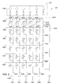
Figure 2 is schematic diagram of one embodiment of the manifold 134 depicted inFigure 1 . Eachmanifold inlet port 104A-F is respectively coupled to an inletgas delivery line 220A-F to facilitate transferring gases from thegas sources 102A-F into themanifold 134. Eachmanifold outlet port 106A-F is respectively coupled to an outletgas delivery line 232A-F. Each of thegas delivery lines 232A-F may be selectively coupled to one or more of the inletgas delivery lines 220A-F. Although the manifold 134 may be configured to interface with any number of inlet gas outlet gas delivery lines, sixgas delivery lines 102A-F and six outletgas delivery lines 232A-F are shown in the embodiment depicted inFigure 2 . Normally, the number of gas inlet delivery lines is commensurate with the number of gas sources. - The inlet
gas delivery lines 220A includes a plurality of connectinglines 250A-F coupling the inletgas delivery line 220A to a respective outletgas delivery line 232A-F.Connecting valves 204A-F are disposed in communication with the connectinglines 250A-F and may be operated to fluidly couple the inletgas delivery line 220A to one or more of the outletgas delivery lines 232A-F through the inletgas delivery line 220A, depending on the selected operational state of thevalves 204A-F.The connecting valves 204A-F selectively couple thegas source 102A to selectedoutlet ports 106A-F, thereby controlling the routing of gas provided fromsource 102A through themanifold 134. For example, if connectingvalve 204A is in an open operational state while connectingvalves 204B-F remain closed, gas from thesource 102A is routed through theoutlet port 106A to the calibration circuit 122. In another example, if connectingvalves 204B-C are in an open operational state while connectingvalves 204A, D-F remain closed, gas from thesource 102A is routed through theoutlet ports 106B-C. Each of the other inletgas delivery lines 220B-F are similarly configured with connectinglines 250A-F andvalves 204A-F for coupling the inletgas delivery lines 220B-F to the respective outletgas delivery lines 232A-F. Reference numerals 250A-F and 204A-F associated with the inletgas delivery lines 220B-F have been omitted to avoid cluttering ofFigure 2 . -
Figure 3 depicts an alternative embodiment of agas manifold 334. Thegas manifold 334 is substantially similar to thegas manifold 134 depicted inFigure 2 , except wherein thegas manifold 334 includes a plurality of variable connectingvalves 304A-F coupling the gasinlet delivery line 220A to each gasoutlet delivery line 232A-F. The variable connectingvalves 304A-F may be adjusted to allow a proportion of the flow passing through the gasinlet delivery line 220A to enter the respective gas outlet delivery line. The variable connectingvalve 304A-F may be a proportional valve, a pinch valve, a throttle valve, a mass flow controller, a needle valve or other flow control device suitable for regulating the flow between the inlet and outlet lines. - The operational state of the variable connecting
valves 304A-F may be controlled to create a desired ratio of flow through the valve relative to flow by-passing the valve, such that thevalves 304A-F operate as a flow ratio controller in theline 220A. The operational state of the variable connectingvalves 304A-F may be adjusted by thecontroller 150 in response to a metric provided by the sensors 190 (not shown inFigure 3 ). In this manner, for example, the ratio of gases provided into two (or more) gasoutlet delivery lines 232A-F from the single gasinput delivery line 220A may be adjusted in response to the metric provided by thesensors 190 so that a target chemistry composition, flow rate and/or pressure may be realized at theoutput 106A-F of themanifold 334. Each of the other inletgas delivery lines 220B-F are similarly configured with connectinglines 250A-F andvalves 304A-F for coupling the inletgas delivery lines 220B-F to the respective outletgas delivery lines 232A-F. Reference numerals 250A-F and 304A-F associated with the inletgas delivery lines 220B-F have been omitted to avoid cluttering ofFigure 3 . - Returning to
Figure 2 , the manifold 134 may additionally include abridging circuit 202. Thebridging circuit 202 includes abridging line 260 that may be selectively coupled to each of theoutput lines 232A-F by arespective selector valve 262A-F. Using thebridging circuit 202, any of the flow components, for example, one of the connecting valves 204, may be coupled to thecalibration circuit 144. Thebridging circuit 202 also allows theMFC 170 associated with a fluid source, forexample source 102A, to be coupled to thecalibration circuit 144 via a secondary route that incorporates the resistance of the connectingvalve 204A. Moreover, thebridging circuit 202 allows eachoutput line 232A-E to be coupled (through theoutput line 232F) to thepurge line 154 from opposite ends, thereby reducing the time required to purge themanifold 134. - A plurality of disconnects may also be provided to allow coupling of
multiple gas manifolds 134. In the embodiment depicted inFigure 2 , a first group ofdisconnects 216A are disposed adjacent eachoutlet port 106A-F while a second group ofdisconnects 216B are disposed in thebridging circuit 202 between the bridgingline 260 and thevalves 262A-F. For example, as shown inFigure 4 , the second group ofdisconnects 216B allows thebridging line 260 of afirst manifold 434A to be removed and afirst end 402 of the gasoutlet delivery line 232A of thefirst manifold 434A to be coupled to asecond end 404 of theoutlet line 232A of asecond manifold 434B using the mating portions ofdisconnects other outlet lines 232B-F (not shown inFigure 3 ) are similarly coupled. It is contemplated that any number of manifolds may be coupled together in this manner. - Returning to
Figure 2 , one ormore sensors 190 as described above may be interfaced with any of thelines 220A-F, 232A-F, 260, 154 to provide a metric indicative of the gas flows and/or chemistries within thesystem 100. The metric provided by thesensors 190 may be utilized by thecontroller 150 to adjust the operational state of the MFC's 170,valves 262A-F, 204A-F, 304A-F or other component of thegas delivery system 100 such that a desired composition, pressure, rate or volume of gases are provided to thechamber 114. The metric may also be utilized to monitor the composition of gases within various portions of thegas delivery system 100 so that the status of purging, chemical mixing, gas changes and the like may be detected in real time, thereby enhancing system response time and minimizing waste of expensive process gases. -
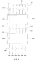
Figure 5 depicts another embodiment of agas delivery system 500 utilized to supply gas to aprocessing chamber 114. Thegas delivery system 500 includes a manifold 134 coupled togas sources 102A-F,purge line 154 and acalibration circuit 144 as described above.Outlet ports 106B-E of the manifold 134 are selectively coupled toinlet port processing chamber 114 to facilitate transferring gases to theprocessing chamber 114. In the embodiment depicted inFigure 5 , two separategas inlet ports processing chamber 114. In one embodiment, theinlet port 516 provides gases to a center of theprocessing chamber 114, whileinlet port 518 is disposed outward of theinlet port 518 and provides gases to the outer regions of the processing chamber (e.g., to the perimeter of the substrate disposed within the chamber). For example, theinlet port 516 may provide gases to center regions of a showerhead while theinlet port 518 may provide gases to outer regions of the showerhead. In another example, theinlet port 516 may be disposed in a ceiling of a processing chamber and provide gases downwardly to a substrate while theinlet port 518 may be disposed in a sidewall of the processing chamber provide gases to outer regions of the substrate. In yet another embodiment, the gases may be provided separately throughinlet ports processing chamber 114. - Flow ratio controllers (FRC) 502, 504 are coupled to each
outlet ports 106D-E. The FRC's 502, 504 split the flows exiting eachoutlet ports 106D-E so that a predetermined flow ratio is provided between eachinlet port processing chamber 114 The FRC's 502, 504 may have a fixed output ratio, or may have an adjustable output ratio. The output of the FRC's 502, 504 and themanifold output ports 106B-C are respectively combined into common delivery lines 522, 524. Flow through each delivery line 522, 524 is controlled by a final valve 508, 506 positioned just upstream of theinlet ports processing chamber 114. - By-pass valves 510, 512 are coupled to each delivery line 522, 524. The by-pass valves 510, 512 may be opened to couple each delivery line 522, 524 to the
purge line 154. - The gas delivery systems described provides many advantages over conventional systems. In addition to the system's modularity, the gas delivery system may be operated to provide pre-flow path, a fast evacuation path, controlled chemical mixing, more efficient use of chemistries, sequenced reduced fill and evacuation times, closed loop control for fine tuning of chemistry delivery and flow verification.
- In one mode of operation, a pre-flow path is defined through the
gas delivery system 100 and provides a connection to the chemistry source (e.g.,sources 102A-F) through one or more valves to a vacuum environment that is separate from the processing chamber 114 (e.g., theforeline 138 through the purge line 154). Before gases are requested in theprocessing chamber 114, the gases may be supplied to the appropriate lines of themanifold 134 of thegas delivery system 100 in a condition that substantially matches the condition of the gas as if it was flowing into theprocessing chamber 114. This allows the gases within the manifold 134 to rapidly reach a steady state condition that is substantially maintained one the gases are diverted into theprocessing chamber 114. Since the pre-flow path allows the gases within thegas delivery system 100 to stabilize in a "process condition" before being delivered into theprocessing chamber 114, there is little or no change in the flow conditions within thedelivery system 100 once flow to the chamber is commenced, unlike conventional gas delivery systems which typically experience a pressure drop and diminished flow rates. Thus, the uniformity of gas delivery in the processing chamber to be quickly established because as the pre-flow path provides substantially the same resistance and flow conditions as if the gases were flowing into the processing chamber. Thethrottle valve 144 may also be utilized to match the conditions in the pre-flow gas path to that of theprocessing chamber 114. - Additionally, any flow dividing devices, such as the
flow ratio controllers valves 304A-F, may have their outputs routed into the pre-flow path prior to processing so that the outputs of the dividing devices can be stabilized before flow is delivered to the processing chamber. In one embodiment, the pre-flow path is defined through thepurge line 154 and the by-pass lines through themanifold outlets 106A-B through the by-pass valves 108A-F and into the purgedline 154. - In another mode of operation, a fast evacuation path is defined in the
gas delivery system 100 and provides a connection from the manifold 134 to theforeline 138 through thepurge line 154. The fast evacuation path provides a connection from the chemical delivery sources through the processing chamber delivery path through one or more valves to a vacuum environment that is separate from the processing chamber 114 (e.g., theforeline 138 through the purge line 154). The fast evacuation path is coupled to each chamber connection such that there is at least one connection between any two flow restrictions, such as theflow ratio controllers valves 304A-F or other flow restriction. When it is required that the chemistry within theprocessing chamber 114 should change, theisolation valve 172 and by-pass valves 108A-E to the vacuum environment will be opened, removing the excess process chemicals from the chemical delivery path. - As discussed above, the operational state of the various valves within the manifold 134 may be sequenced such that the purge time of chemicals being removed from the
gas delivery system 100 through the fast evacuation path is minimized. Additionally, the operational state of thevalves 204A-F may also be sequenced so that as certain regions the manifold 134 are emptied of the chemicals utilized in the previous process, the emptied regions may be then filled with the new chemistry, such that the gases within the manifold 134 are replaced in the most efficient manner. Moreover, as certain portions of the manifold 134 are evacuated more quickly relative to other portions of the manifold, sequencing thevalves 204A-F may be made in a manner that allows the new chemicals replacing the old chemicals to reach equilibrium (e.g., processing flow conditions) in the shortest time possible. - In one embodiment, higher pressure, volume and/or flow of replacement gases from the
sources 102A-F may be provided to one or more regions of the manifold 134 to expedite changeover. As the flow of replacement gases exiting the manifold 134 approaches the desired chemical mix, pressure and/or volume, the flow of chemicals into thechemical delivery system 100 may be reduced to the desired levels in a manner that maintains a desired flow out of themanifold 134. In cases where thechemical delivery system 100 will be filled with chemicals from earlier processes, flows into the chemical delivery system may be altered (i.e., reduced or increased, depending on the desired effect) so that the desired flow into the processing chamber will reach the desired values as quickly as possible. As the chemical flow out of the manifold approaches the desired chemical mix and flow rate, the flow of chemicals into the manifold 134 will be adjusted toward the desired flow rates in a manner that maintains the desired flow into theprocessing chamber 114. - In another embodiment, chemistry change may be expedited by sequencing the
valves 204A-F such that onlygas delivery lines 232A-F containing gas which have not yet been replaced maintain coupled to thepurge line 154. Once replacement gas is detected exiting the manifold 134 from one of thegas delivery lines 232A-F or at another predefined location, thatgas delivery line 232A-F supplying the replacement gas is disconnected from thepurge line 154 so that the replacement gas is not wasted. In one embodiment, the replacement gas may be diverted from thepurge line 154 into theprocessing chamber 114 until the change over is completed. In this manner, the pumping capacity of thepurge line 154 is dedicated to only those lines requiring gas removal so that change over of processing gases may be made in an efficient manner. It is also contemplated that the fastest evacuation path may include routing gas flows through thebridging circuit 202 to thepurge line 154 for at least a portion of the change over time. - In another mode of operation, the
gas delivery system 100 may be utilized to enhance chemical mixing. In one embodiment, chemical mixing may occur within the manifold 134 using thevalves 304A-F or by coupling two ormore sources 102A-F to a single gasoutlet delivery line 232A-F. - In another embodiment, the
sensors 190 may be utilized to provide closed loop control of the chemical mixing within the gas delivery system. By monitoring the chemistries entering thechamber 114, exiting the manifold 134 and/ or at any other point within thegas delivery system 100 using thesensors 190, real time adjustment of chemistry parameters, such as desired composition (e.g., gas mix), rate and/or pressure, may be realized. For example, if sensors detect an improper flow ratio of chemistry fromsources 102A-B exiting the manifold atport 106C, the operational state of thevalves 304C couplinginlet delivery lines 220A-220B tooutlet delivery line 232C may be adjusted to bring the chemistry flows to a desired target ratio. The same process may be performed using the other valves or flow ratio controllers. Information from thesensors 190 may also be utilized to adjust the MFC settings, flow rates and/or pressures of the gases provided from thesources 102A-F. - In another mode of operation, the
gas delivery system 100 enhances efficient use of chemistries. For example, the sequence of in which the operational states of thevalves 204A-F, 172, 108A-E, 262A-F are changed may be arranged in a manner that removes gases from the manifold 134 most effectively and with minimal mixing of gases, thereby allowing faster response time and reduced processing time. Thus, during gas changes, the rate that gases are drawn through the delivery path (e.g., throughoutlet lines 232A-F) and into thepurge line 154 may be adjusted using thethrottle valve 156 to advance the gases quickly through themanifold 134. Moreover, while thepurge line 154 is drawing gases through the manifold 134, lines which are contain gases ready for the next processing sequence, such as newly introduced gases, purge gas and/or the last remnants of gases previously contained in the manifold, may be diverted from thepurge line 154 and flowed into theprocessing chamber 114. This allows the remaining lines coupled to thepurge line 154 to be evacuated more rapidly. In one embodiment, a metric provided by thesensors 190 may be utilized to indicate when a diversion from thepurge line 154 to thechamber 114 should occur, for example, by a change or stabilization in the composition of the gases, flow rate and or pressure of gases within the line. - In another mode of operation, the
gas delivery system 100 may be utilized to verify the flow rates of any of the components within the system using thecalibration circuit 144. For example, the valves of thesystem 100 may provide flow from any one of the inlet ports to thecalibration circuit 144. In another example, flows divided by valves of the system may be verified for flow rates along each branch of the divided flow. -
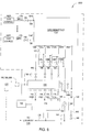
Figure 6 is a simplified schematic of asemiconductor processing chamber 114 coupled to another embodiment of agas delivery system 600. Thegas delivery system 600 is configured substantially similar to the gas delivery systems describe above, except wherein thesystem 600 includes astorage tank 630 coupled to at least one of theoutput ports 106A-F of the system'smanifold 134. Thestorage tank 630 may be coupled to the at least one or more of theprocessing chamber 114, a second processing chamber 614 (shown in phantom), a gas delivery system 100 (500 or 600) of thesecond processing chamber 614, thecalibration circuit 144 or thefacility exhaust 136. Asensor 190 may be provided to provide a metric indicative of the gas within thetank 630. In one embodiment, the metric may be indicative of the gas pressure, gas composition (e.g., chemistry), temperature or other characteristic. - In one embodiment, each
output port 106A-F may be individually coupled to thetank 630. In another embodiment, thetank 630 may be segmented (as shown in phantom) so that each 106A-F may be retained in thetank 630 without mixing, then individually coupled to theprocessing chamber 114. Alternatively,separate tanks 630 may be use. It is also contemplated that the inlet of thetank 630 may be utilized to deliver gases to theprocessing chamber 114. - Thus, gas delivery systems having fast evacuation paths that advantageously enable processing gases supplying from the gas delivery systems into a processing system with stable gas flow and minimum fluctuation. The fast evacuation paths are utilized to provide an alternative manner to verify and/or calibrate gas flows from the gas delivery systems, thereby providing good control of the gas flow supplying to the processing system.
- While the foregoing is directed to embodiments of the present invention, other and further embodiments of the invention may be devised without departing from the basic scope thereof, and the scope thereof is determined by the claims that follow.
Claims (15)
- A method of controlling gas flow to a processing system that includes a processing chamber coupled to a facility exhaust through a foreline, comprising:flowing a first gas from a first gas source into a manifold having at least a first outlet port, a second outlet port, a third outlet port and a fourth outlet port;flowing a second gas from a second gas source into the manifold;selecting an operational state of valves within the manifold to cause the first and second gases to exit through at least one of the second or third outlet ports while in a processing mode;flowing the first and second gases through the manifold and into the foreline by-passing the processing chamber until a predefine state of the gases within the manifold is obtained;directing the first and second gases exiting the manifold into the processing chamber after the predefine state has been obtained; andprocessing a substrate within the processing chamber.
- The method of claim 1 further comprising:flowing the first and second gases through the manifold into the foreline by-passing the processing chamber after substrate processing is complete.
- The method of claim 2 further comprising:replacing at least one of the first and second gases in the manifold with a third gas provided to the manifold from a third gas source.
- The method of claim 3 further comprising:preventing at least one of the third gas exiting the manifold from entering the purge line or stopping the flow of the third gas; andcontinuing to draw at least one of the first or second gas into the purge line while the third gas is exiting the manifold.
- The method of claim 2, wherein at least one of preventing the third gas from entering the purge line or stopping the flow of the third gas further comprises:flowing the third gas into the processing chamber.
- The method of claim 2, wherein at least one of preventing the third gas from entering the purge line or stopping the flow of the third gas further comprises:decoupling the outlet through which the third gas is exiting the manifold from the purge line.
- The method of claim 1 further comprising:adjusting the operational state of at least one valve in the manifold to obtain a ratio of flows from one gas source through at least two outlet ports.
- The method of claim 7, wherein adjusting the operational state of the at least one valve in the manifold further comprises:sensing a metric of the gas exiting the manifold; andadjusting the operational state of the at least one valve in the manifold to change the ratio of flows through the at least two outlet ports.
- The method of claim 1 further comprising:sensing a metric of the gas exiting the manifold; andadjusting the flow of at least one gas entering the manifold in response to the sensed metric.
- The method of claim 1 further comprising:sensing a metric of the gas entering the chamber; andadjusting at least one flow ratio controller in response to the sensed metric.
- The method of claim 1 further comprising:sensing a metric of the gas entering the chamber; andadjusting a composition of the gas entering the chamber in response to the sensed metric.
- The method of claim 1 further comprising:sensing a metric of the gas entering the chamber; andadjusting a pressure of the gas entering the chamber in response to the sensed metric.
- The method of claim 1 further comprising:selecting an operational state of the valves within the manifold to cause at least one of the first and second gases to exit through the fourth outlet port and into a calibration circuit.
- A method of controlling gas flow to a processing system that includes a processing chamber coupled to a facility exhaust through a foreline, comprising:providing a manifold having at least a first, second third and fourth inlet that may be selectively coupled to at least one of a first, second third and fourth outlet;flowing one or more gases through the manifold to a vacuum environment by-passing the processing chamber prior to processing or to a calibration circuit; andflowing the one or more gases into the processing chamber during substrate processing.
- The method of claim 14, wherein flowing one or more gases through the manifold to the vacuum environment further comprises:waiting until the flow of gases meets a predefined criteria prior to diverting the flow to the processing chamber.
Applications Claiming Priority (1)
| Application Number | Priority Date | Filing Date | Title |
|---|---|---|---|
| US11/678,623 US7846497B2 (en) | 2007-02-26 | 2007-02-26 | Method and apparatus for controlling gas flow to a processing chamber |
Publications (1)
| Publication Number | Publication Date |
|---|---|
| EP1961838A1 true EP1961838A1 (en) | 2008-08-27 |
Family
ID=39589491
Family Applications (1)
| Application Number | Title | Priority Date | Filing Date |
|---|---|---|---|
| EP20080151408 Withdrawn EP1961838A1 (en) | 2007-02-26 | 2008-02-14 | Method and apparatus for comtrolling gas flow to a processing chamber |
Country Status (7)
| Country | Link |
|---|---|
| US (1) | US7846497B2 (en) |
| EP (1) | EP1961838A1 (en) |
| JP (1) | JP5330709B2 (en) |
| KR (1) | KR100975441B1 (en) |
| CN (1) | CN101256935B (en) |
| SG (1) | SG145668A1 (en) |
| TW (1) | TW200846860A (en) |
Cited By (2)
| Publication number | Priority date | Publication date | Assignee | Title |
|---|---|---|---|---|
| AT521586A2 (en) * | 2018-08-28 | 2020-03-15 | Avl List Gmbh | Gas mixing device for linearization or calibration of gas analyzers |
| WO2022246076A1 (en) * | 2021-05-21 | 2022-11-24 | Lam Research Corporation | Tungsten wordline fill in high aspect ratio 3d nand architecture |
Families Citing this family (48)
| Publication number | Priority date | Publication date | Assignee | Title |
|---|---|---|---|---|
| JP2006253696A (en) * | 2005-03-10 | 2006-09-21 | Asm America Inc | Gas injector control system |
| US7743670B2 (en) * | 2006-08-14 | 2010-06-29 | Applied Materials, Inc. | Method and apparatus for gas flow measurement |
| JP5372353B2 (en) * | 2007-09-25 | 2013-12-18 | 株式会社フジキン | Gas supply equipment for semiconductor manufacturing equipment |
| US20090236447A1 (en) * | 2008-03-21 | 2009-09-24 | Applied Materials, Inc. | Method and apparatus for controlling gas injection in process chamber |
| US8623141B2 (en) * | 2009-05-18 | 2014-01-07 | Taiwan Semiconductor Manufacturing Co., Ltd. | Piping system and control for semiconductor processing |
| US8747762B2 (en) | 2009-12-03 | 2014-06-10 | Applied Materials, Inc. | Methods and apparatus for treating exhaust gas in a processing system |
| CN101989068B (en) * | 2010-11-05 | 2012-07-18 | 北京七星华创电子股份有限公司 | Simulation process system and method based on quality flow controller |
| JP2012195565A (en) * | 2011-02-28 | 2012-10-11 | Hitachi Kokusai Electric Inc | Substrate processing apparatus, substrate processing method, and manufacturing method of semiconductor device |
| US9175808B2 (en) * | 2011-06-17 | 2015-11-03 | Lam Research Corporation | System and method for decreasing scrubber exhaust from gas delivery panels |
| US9305810B2 (en) * | 2011-06-30 | 2016-04-05 | Applied Materials, Inc. | Method and apparatus for fast gas exchange, fast gas switching, and programmable gas delivery |
| CN103177923B (en) * | 2011-12-20 | 2016-05-11 | 中微半导体设备(上海)有限公司 | A kind of gas distributed system and verification method that is applied to plasma treatment appts |
| US9238865B2 (en) * | 2012-02-06 | 2016-01-19 | Asm Ip Holding B.V. | Multiple vapor sources for vapor deposition |
| US20130255784A1 (en) * | 2012-03-30 | 2013-10-03 | Applied Materials, Inc. | Gas delivery systems and methods of use thereof |
| US9410244B2 (en) * | 2012-09-04 | 2016-08-09 | Asm Ip Holding B.V. | Semiconductor processing apparatus including a plurality of reactors, and method for providing the same with process gas |
| US20140137961A1 (en) * | 2012-11-19 | 2014-05-22 | Applied Materials, Inc. | Modular chemical delivery system |
| US8893923B2 (en) * | 2012-11-28 | 2014-11-25 | Intermolecular, Inc. | Methods and systems for dispensing different liquids for high productivity combinatorial processing |
| US9488315B2 (en) * | 2013-03-15 | 2016-11-08 | Applied Materials, Inc. | Gas distribution apparatus for directional and proportional delivery of process gas to a process chamber |
| JP6336719B2 (en) * | 2013-07-16 | 2018-06-06 | 株式会社ディスコ | Plasma etching equipment |
| US10161060B2 (en) | 2013-12-19 | 2018-12-25 | Taiwan Semiconductor Manufacturing Co., Ltd. | Gas-supply system and method |
| US9632516B2 (en) * | 2013-12-19 | 2017-04-25 | Tawan Semiconductor Manufacturing Co., Ltd | Gas-supply system and method |
| JP2016081945A (en) * | 2014-10-09 | 2016-05-16 | 株式会社ニューフレアテクノロジー | Vapor growth device and vapor phase epitaxy method |
| TW201634738A (en) * | 2015-01-22 | 2016-10-01 | 應用材料股份有限公司 | Improved injector for spatially separated atomic layer deposition chamber |
| CN106025158B (en) * | 2015-03-27 | 2020-08-11 | 株式会社杰士汤浅国际 | Electric storage element |
| US10957561B2 (en) * | 2015-07-30 | 2021-03-23 | Lam Research Corporation | Gas delivery system |
| US10192751B2 (en) | 2015-10-15 | 2019-01-29 | Lam Research Corporation | Systems and methods for ultrahigh selective nitride etch |
| US10825659B2 (en) | 2016-01-07 | 2020-11-03 | Lam Research Corporation | Substrate processing chamber including multiple gas injection points and dual injector |
| US10256075B2 (en) * | 2016-01-22 | 2019-04-09 | Applied Materials, Inc. | Gas splitting by time average injection into different zones by fast gas valves |
| US10651015B2 (en) | 2016-02-12 | 2020-05-12 | Lam Research Corporation | Variable depth edge ring for etch uniformity control |
| US10147588B2 (en) | 2016-02-12 | 2018-12-04 | Lam Research Corporation | System and method for increasing electron density levels in a plasma of a substrate processing system |
| US10699878B2 (en) | 2016-02-12 | 2020-06-30 | Lam Research Corporation | Chamber member of a plasma source and pedestal with radially outward positioned lift pins for translation of a substrate c-ring |
| US10438833B2 (en) | 2016-02-16 | 2019-10-08 | Lam Research Corporation | Wafer lift ring system for wafer transfer |
| US10453721B2 (en) | 2016-03-15 | 2019-10-22 | Applied Materials, Inc. | Methods and assemblies for gas flow ratio control |
| US10269600B2 (en) * | 2016-03-15 | 2019-04-23 | Applied Materials, Inc. | Methods and assemblies for gas flow ratio control |
| US10410832B2 (en) | 2016-08-19 | 2019-09-10 | Lam Research Corporation | Control of on-wafer CD uniformity with movable edge ring and gas injection adjustment |
| US10604841B2 (en) | 2016-12-14 | 2020-03-31 | Lam Research Corporation | Integrated showerhead with thermal control for delivering radical and precursor gas to a downstream chamber to enable remote plasma film deposition |
| CN108231620B (en) * | 2016-12-15 | 2021-01-19 | 中微半导体设备(上海)股份有限公司 | Gas flow control device and gas flow control method thereof |
| GB2557670B (en) * | 2016-12-15 | 2020-04-15 | Thermo Fisher Scient Bremen Gmbh | Improved gas flow control |
| WO2018148062A1 (en) | 2017-02-09 | 2018-08-16 | Applied Materials, Inc. | Plasma abatement technology utilizing water vapor and oxygen reagent |
| JP6392492B1 (en) * | 2017-04-20 | 2018-09-19 | 株式会社ブイテックス | Vacuum container internal pressure multi-control device and vacuum container internal pressure multi-control method |
| WO2019067323A1 (en) * | 2017-09-26 | 2019-04-04 | Lam Research Corporation | Systems and methods for pulse width modulated dose control |
| KR20200106090A (en) | 2018-01-31 | 2020-09-10 | 램 리써치 코포레이션 | Manifold valve for multiple precursors |
| CN109884255A (en) * | 2019-03-26 | 2019-06-14 | 翼捷安全设备(昆山)有限公司 | High-precision full-automatic air distribution system and method |
| US11788190B2 (en) | 2019-07-05 | 2023-10-17 | Asm Ip Holding B.V. | Liquid vaporizer |
| US11946136B2 (en) | 2019-09-20 | 2024-04-02 | Asm Ip Holding B.V. | Semiconductor processing device |
| TW202128273A (en) * | 2019-10-08 | 2021-08-01 | 荷蘭商Asm Ip私人控股有限公司 | Gas injection system, reactor system, and method of depositing material on surface of substratewithin reaction chamber |
| JP7296854B2 (en) * | 2019-11-07 | 2023-06-23 | 東京エレクトロン株式会社 | Gas supply method and substrate processing apparatus |
| WO2022186971A1 (en) | 2021-03-03 | 2022-09-09 | Ichor Systems, Inc. | Fluid flow control system comprising a manifold assembly |
| US11940819B1 (en) * | 2023-01-20 | 2024-03-26 | Applied Materials, Inc. | Mass flow controller based fast gas exchange |
Citations (5)
| Publication number | Priority date | Publication date | Assignee | Title |
|---|---|---|---|---|
| US5254210A (en) * | 1992-04-27 | 1993-10-19 | The United States Of America As Represented By The Secretary Of The Army | Method and apparatus for growing semiconductor heterostructures |
| US5589110A (en) * | 1992-11-20 | 1996-12-31 | Mitsubishi Electric Corp | Container for liquid metal organic compound |
| WO2002008487A1 (en) * | 2000-07-24 | 2002-01-31 | The University Of Maryland, College Park | Spatially programmable microelectronics process equipment using segmented gas injection showerhead with exhaust gas recirculation |
| US6773749B1 (en) * | 1999-09-20 | 2004-08-10 | Moore Epitaxial Inc. | Method of controlling gas flow to a semiconductor processing reactor |
| US20040163590A1 (en) * | 2003-02-24 | 2004-08-26 | Applied Materials, Inc. | In-situ health check of liquid injection vaporizer |
Family Cites Families (69)
| Publication number | Priority date | Publication date | Assignee | Title |
|---|---|---|---|---|
| JPS5292788A (en) | 1976-01-30 | 1977-08-04 | Standard Technology | Gas diluting apparatus |
| US4887020A (en) * | 1984-07-23 | 1989-12-12 | U.S. Philips Corporation | Self-compensating brushless alternator |
| US4590790A (en) | 1985-05-16 | 1986-05-27 | American Meter Company | Method for determining the accuracy of a gas measurement instrument |
| US4687020A (en) | 1985-05-17 | 1987-08-18 | Doyle James H | Fluid mass flow controller |
| US4761269A (en) | 1986-06-12 | 1988-08-02 | Crystal Specialties, Inc. | Apparatus for depositing material on a substrate |
| US4911101A (en) | 1988-07-20 | 1990-03-27 | General Electric Company | Metal organic molecular beam epitaxy (MOMBE) apparatus |
| JP2888253B2 (en) | 1989-07-20 | 1999-05-10 | 富士通株式会社 | Chemical vapor deposition and apparatus for its implementation |
| JPH03156509A (en) | 1989-11-14 | 1991-07-04 | Stec Kk | Mass flow controller |
| US5062446A (en) | 1991-01-07 | 1991-11-05 | Sematech, Inc. | Intelligent mass flow controller |
| US5190058A (en) * | 1991-05-22 | 1993-03-02 | Medtronic, Inc. | Method of using a temporary stent catheter |
| US5141021A (en) | 1991-09-06 | 1992-08-25 | Stec Inc. | Mass flow meter and mass flow controller |
| US5303731A (en) | 1992-06-30 | 1994-04-19 | Unit Instruments, Inc. | Liquid flow controller |
| US5190068A (en) | 1992-07-02 | 1993-03-02 | Brian Philbin | Control apparatus and method for controlling fluid flows and pressures |
| US5293778A (en) | 1993-05-27 | 1994-03-15 | General Electric Company | Fluid flow measuring system |
| WO1995019549A1 (en) | 1994-01-14 | 1995-07-20 | Unit Instruments, Inc. | Flow meter |
| US5524084A (en) | 1994-12-30 | 1996-06-04 | Hewlett-Packard Company | Method and apparatus for improved flow and pressure measurement and control |
| US5653807A (en) | 1996-03-28 | 1997-08-05 | The United States Of America As Represented By The Secretary Of The Air Force | Low temperature vapor phase epitaxial system for depositing thin layers of silicon-germanium alloy |
| US5662143A (en) | 1996-05-16 | 1997-09-02 | Gasonics International | Modular gas box system |
| US5944048A (en) | 1996-10-04 | 1999-08-31 | Emerson Electric Co. | Method and apparatus for detecting and controlling mass flow |
| US5911238A (en) | 1996-10-04 | 1999-06-15 | Emerson Electric Co. | Thermal mass flowmeter and mass flow controller, flowmetering system and method |
| US6937366B2 (en) * | 1996-12-26 | 2005-08-30 | Canon Kabushiki Kaisha | Data communication system |
| JPH10240356A (en) | 1997-02-21 | 1998-09-11 | Anelva Corp | Method for controlling substrate temperature and discriminating substrate temperature controllability for substrate processor |
| KR100251645B1 (en) | 1997-03-21 | 2000-04-15 | 윤종용 | Sample gas distributing method coupled by process gas evaluation apparatus |
| US5865205A (en) * | 1997-04-17 | 1999-02-02 | Applied Materials, Inc. | Dynamic gas flow controller |
| US5966499A (en) | 1997-07-28 | 1999-10-12 | Mks Instruments, Inc. | System for delivering a substantially constant vapor flow to a chemical process reactor |
| KR100269315B1 (en) * | 1997-11-24 | 2000-11-01 | 윤종용 | Method for fabricating a semiconductor device using single wafer loading type apparatus adoping lamp heating method |
| TW437017B (en) | 1998-02-05 | 2001-05-28 | Asm Japan Kk | Silicone polymer insulation film on semiconductor substrate and method for formation thereof |
| US6269692B1 (en) | 1999-02-01 | 2001-08-07 | Dxl Usa Inc. | Mass flow measuring assembly having low pressure drop and fast response time |
| EP1096351A4 (en) | 1999-04-16 | 2004-12-15 | Fujikin Kk | Parallel bypass type fluid feeding device, and method and device for controlling fluid variable type pressure system flow rate used for the device |
| US6210482B1 (en) | 1999-04-22 | 2001-04-03 | Fujikin Incorporated | Apparatus for feeding gases for use in semiconductor manufacturing |
| US6733590B1 (en) | 1999-05-03 | 2004-05-11 | Seagate Technology Llc. | Method and apparatus for multilayer deposition utilizing a common beam source |
| US6119710A (en) | 1999-05-26 | 2000-09-19 | Cyber Instrument Technologies Llc | Method for wide range gas flow system with real time flow measurement and correction |
| US6343617B1 (en) | 1999-07-09 | 2002-02-05 | Millipore Corporation | System and method of operation of a digital mass flow controller |
| US6389364B1 (en) | 1999-07-10 | 2002-05-14 | Mykrolis Corporation | System and method for a digital mass flow controller |
| US6138708A (en) | 1999-07-28 | 2000-10-31 | Controls Corporation Of America | Mass flow controller having automatic pressure compensator |
| JP2001185542A (en) * | 1999-12-27 | 2001-07-06 | Hitachi Ltd | Plasma processor and plasma processing method using the same |
| US6772781B2 (en) * | 2000-02-04 | 2004-08-10 | Air Liquide America, L.P. | Apparatus and method for mixing gases |
| KR100332313B1 (en) | 2000-06-24 | 2002-04-12 | 서성기 | Apparatus and method for depositing thin film on wafer |
| AU2001286619A1 (en) | 2000-08-22 | 2002-03-04 | Fugasity Corporation | Fluid mass flow meter with substantial measurement range |
| US6333272B1 (en) | 2000-10-06 | 2001-12-25 | Lam Research Corporation | Gas distribution apparatus for semiconductor processing |
| DE10051973A1 (en) * | 2000-10-20 | 2002-05-02 | Bosch Gmbh Robert | Micromechanical component has seismic mass sprung-mounted by double U spring to be deflectable by external acceleration, stop(s) protrusion for limiting deflection of double U spring |
| US6814096B2 (en) | 2000-12-15 | 2004-11-09 | Nor-Cal Products, Inc. | Pressure controller and method |
| US6800173B2 (en) | 2000-12-15 | 2004-10-05 | Novellus Systems, Inc. | Variable gas conductance control for a process chamber |
| US6439253B1 (en) | 2000-12-28 | 2002-08-27 | International Business Machines Corporation | System for and method of monitoring the flow of semiconductor process gases from a gas delivery system |
| AU2002307547A1 (en) | 2001-04-24 | 2002-11-05 | Unit Instruments, Inc. | System and method for configuring and asapting a mass flow controller |
| KR20040019293A (en) * | 2001-05-24 | 2004-03-05 | 셀레리티 그룹 아이엔씨 | Method and apparatus for providing a determined ratio of process fluids |
| US20030070620A1 (en) * | 2001-10-15 | 2003-04-17 | Cooperberg David J. | Tunable multi-zone gas injection system |
| WO2003089682A1 (en) | 2002-04-19 | 2003-10-30 | Mattson Technology, Inc. | System for depositing a film onto a substrate using a low vapor pressure gas precursor |
| US20040040664A1 (en) | 2002-06-03 | 2004-03-04 | Yang Jang Gyoo | Cathode pedestal for a plasma etch reactor |
| US7004191B2 (en) | 2002-06-24 | 2006-02-28 | Mks Instruments, Inc. | Apparatus and method for mass flow controller with embedded web server |
| US7552015B2 (en) | 2002-06-24 | 2009-06-23 | Mks Instruments, Inc. | Apparatus and method for displaying mass flow controller pressure |
| US7136767B2 (en) | 2002-06-24 | 2006-11-14 | Mks Instruments, Inc. | Apparatus and method for calibration of mass flow controller |
| US6810308B2 (en) | 2002-06-24 | 2004-10-26 | Mks Instruments, Inc. | Apparatus and method for mass flow controller with network access to diagnostics |
| US6712084B2 (en) | 2002-06-24 | 2004-03-30 | Mks Instruments, Inc. | Apparatus and method for pressure fluctuation insensitive mass flow control |
| US6821347B2 (en) | 2002-07-08 | 2004-11-23 | Micron Technology, Inc. | Apparatus and method for depositing materials onto microelectronic workpieces |
| AU2003253991A1 (en) | 2002-07-19 | 2004-02-09 | Celerity Group, Inc. | Methods and apparatus for pressure compensation in a mass flow controller |
| CN100422616C (en) | 2002-08-28 | 2008-10-01 | 霍里巴斯特克公司 | Higher accuracy pressure based flow controller |
| US20040050326A1 (en) | 2002-09-12 | 2004-03-18 | Thilderkvist Karin Anna Lena | Apparatus and method for automatically controlling gas flow in a substrate processing system |
| US7169231B2 (en) | 2002-12-13 | 2007-01-30 | Lam Research Corporation | Gas distribution system with tuning gas |
| US6898558B2 (en) | 2002-12-31 | 2005-05-24 | Tokyo Electron Limited | Method and apparatus for monitoring a material processing system |
| US20050120805A1 (en) | 2003-12-04 | 2005-06-09 | John Lane | Method and apparatus for substrate temperature control |
| US7072743B2 (en) | 2004-03-09 | 2006-07-04 | Mks Instruments, Inc. | Semiconductor manufacturing gas flow divider system and method |
| US7708859B2 (en) * | 2004-04-30 | 2010-05-04 | Lam Research Corporation | Gas distribution system having fast gas switching capabilities |
| US7408772B2 (en) * | 2004-05-14 | 2008-08-05 | Hewlett-Packard Development Company, L.P. | Fan tray electronics enclosure |
| US7412986B2 (en) * | 2004-07-09 | 2008-08-19 | Celerity, Inc. | Method and system for flow measurement and validation of a mass flow controller |
| US20060068098A1 (en) | 2004-09-27 | 2006-03-30 | Tokyo Electron Limited | Deposition of ruthenium metal layers in a thermal chemical vapor deposition process |
| US20060124169A1 (en) | 2004-12-09 | 2006-06-15 | Tokyo Electron Limited | Gas supply unit, substrate processing apparatus, and supply gas setting method |
| US7174263B2 (en) * | 2005-03-25 | 2007-02-06 | Mks Instruments, Inc. | External volume insensitive flow verification |
| US20070021935A1 (en) | 2005-07-12 | 2007-01-25 | Larson Dean J | Methods for verifying gas flow rates from a gas supply system into a plasma processing chamber |
-
2007
- 2007-02-26 US US11/678,623 patent/US7846497B2/en not_active Expired - Fee Related
-
2008
- 2008-02-14 EP EP20080151408 patent/EP1961838A1/en not_active Withdrawn
- 2008-02-20 SG SG200801437-5A patent/SG145668A1/en unknown
- 2008-02-25 KR KR1020080016714A patent/KR100975441B1/en not_active IP Right Cessation
- 2008-02-25 JP JP2008043004A patent/JP5330709B2/en not_active Expired - Fee Related
- 2008-02-26 CN CN2008100063306A patent/CN101256935B/en not_active Expired - Fee Related
- 2008-02-26 TW TW97106678A patent/TW200846860A/en unknown
Patent Citations (5)
| Publication number | Priority date | Publication date | Assignee | Title |
|---|---|---|---|---|
| US5254210A (en) * | 1992-04-27 | 1993-10-19 | The United States Of America As Represented By The Secretary Of The Army | Method and apparatus for growing semiconductor heterostructures |
| US5589110A (en) * | 1992-11-20 | 1996-12-31 | Mitsubishi Electric Corp | Container for liquid metal organic compound |
| US6773749B1 (en) * | 1999-09-20 | 2004-08-10 | Moore Epitaxial Inc. | Method of controlling gas flow to a semiconductor processing reactor |
| WO2002008487A1 (en) * | 2000-07-24 | 2002-01-31 | The University Of Maryland, College Park | Spatially programmable microelectronics process equipment using segmented gas injection showerhead with exhaust gas recirculation |
| US20040163590A1 (en) * | 2003-02-24 | 2004-08-26 | Applied Materials, Inc. | In-situ health check of liquid injection vaporizer |
Cited By (4)
| Publication number | Priority date | Publication date | Assignee | Title |
|---|---|---|---|---|
| AT521586A2 (en) * | 2018-08-28 | 2020-03-15 | Avl List Gmbh | Gas mixing device for linearization or calibration of gas analyzers |
| AT521586A3 (en) * | 2018-08-28 | 2020-12-15 | Avl List Gmbh | Gas mixing device for linearization or calibration of gas analyzers |
| AT521586B1 (en) * | 2018-08-28 | 2020-12-15 | Avl List Gmbh | Gas mixing device for linearization or calibration of gas analyzers |
| WO2022246076A1 (en) * | 2021-05-21 | 2022-11-24 | Lam Research Corporation | Tungsten wordline fill in high aspect ratio 3d nand architecture |
Also Published As
| Publication number | Publication date |
|---|---|
| SG145668A1 (en) | 2008-09-29 |
| US20080202588A1 (en) | 2008-08-28 |
| KR20080079210A (en) | 2008-08-29 |
| CN101256935B (en) | 2011-08-17 |
| US7846497B2 (en) | 2010-12-07 |
| TW200846860A (en) | 2008-12-01 |
| KR100975441B1 (en) | 2010-08-11 |
| CN101256935A (en) | 2008-09-03 |
| JP5330709B2 (en) | 2013-10-30 |
| JP2008211219A (en) | 2008-09-11 |
Similar Documents
| Publication | Publication Date | Title |
|---|---|---|
| US7846497B2 (en) | Method and apparatus for controlling gas flow to a processing chamber | |
| US7775236B2 (en) | Method and apparatus for controlling gas flow to a processing chamber | |
| US8074677B2 (en) | Method and apparatus for controlling gas flow to a processing chamber | |
| US6418954B1 (en) | System and method for dividing flow | |
| KR101451091B1 (en) | Methods and apparatus for calibrating flow controllers in substrate processing systems | |
| US20100229976A1 (en) | Flow rate ratio variable type fluid supply apparatus | |
| JP2017050531A (en) | Gas supply system | |
| KR20050011333A (en) | Gas supply apparatus and semiconductor device manufacturing equipment using the same | |
| JP4235076B2 (en) | Semiconductor manufacturing apparatus and semiconductor manufacturing method | |
| GB2385680A (en) | A system for dividing a mass flow into a plurality of mass flows in a controlled ratio | |
| KR20140088040A (en) | Gas supply systems for substrate processing chambers and methods therefor | |
| KR20100014838A (en) | Gas delivery method and system including a flow ratio controller using a multiple antisymmetric optimal control arrangement | |
| KR20140121904A (en) | Methods and apparatus for reducing flow splitting errors using orifice ratio conductance control | |
| CN114424138A (en) | Low-temperature heat flow ratio controller | |
| CN110021541A (en) | Dynamic cooling agent mix manifold containing |
Legal Events
| Date | Code | Title | Description |
|---|---|---|---|
| PUAI | Public reference made under article 153(3) epc to a published international application that has entered the european phase |
Free format text: ORIGINAL CODE: 0009012 |
|
| AK | Designated contracting states |
Kind code of ref document: A1 Designated state(s): AT BE BG CH CY CZ DE DK EE ES FI FR GB GR HR HU IE IS IT LI LT LU LV MC MT NL NO PL PT RO SE SI SK TR |
|
| AX | Request for extension of the european patent |
Extension state: AL BA MK RS |
|
| AKX | Designation fees paid | ||
| STAA | Information on the status of an ep patent application or granted ep patent |
Free format text: STATUS: THE APPLICATION IS DEEMED TO BE WITHDRAWN |
|
| 18D | Application deemed to be withdrawn |
Effective date: 20090228 |
|
| REG | Reference to a national code |
Ref country code: DE Ref legal event code: 8566 |