EP1961596A2 - Combined heating & air conditioning system for buses utilizing an electrified compressor having a modular high-pressure unit - Google Patents
Combined heating & air conditioning system for buses utilizing an electrified compressor having a modular high-pressure unit Download PDFInfo
- Publication number
- EP1961596A2 EP1961596A2 EP08250597A EP08250597A EP1961596A2 EP 1961596 A2 EP1961596 A2 EP 1961596A2 EP 08250597 A EP08250597 A EP 08250597A EP 08250597 A EP08250597 A EP 08250597A EP 1961596 A2 EP1961596 A2 EP 1961596A2
- Authority
- EP
- European Patent Office
- Prior art keywords
- heat exchanger
- refrigerant
- heating
- loop
- air
- Prior art date
- Legal status (The legal status is an assumption and is not a legal conclusion. Google has not performed a legal analysis and makes no representation as to the accuracy of the status listed.)
- Withdrawn
Links
Images


Classifications
-
- B—PERFORMING OPERATIONS; TRANSPORTING
- B60—VEHICLES IN GENERAL
- B60H—ARRANGEMENTS OF HEATING, COOLING, VENTILATING OR OTHER AIR-TREATING DEVICES SPECIALLY ADAPTED FOR PASSENGER OR GOODS SPACES OF VEHICLES
- B60H1/00—Heating, cooling or ventilating [HVAC] devices
- B60H1/00642—Control systems or circuits; Control members or indication devices for heating, cooling or ventilating devices
- B60H1/00814—Control systems or circuits characterised by their output, for controlling particular components of the heating, cooling or ventilating installation
- B60H1/00878—Control systems or circuits characterised by their output, for controlling particular components of the heating, cooling or ventilating installation the components being temperature regulating devices
- B60H1/00899—Controlling the flow of liquid in a heat pump system
- B60H1/00907—Controlling the flow of liquid in a heat pump system where the flow direction of the refrigerant changes and an evaporator becomes condenser
-
- F—MECHANICAL ENGINEERING; LIGHTING; HEATING; WEAPONS; BLASTING
- F25—REFRIGERATION OR COOLING; COMBINED HEATING AND REFRIGERATION SYSTEMS; HEAT PUMP SYSTEMS; MANUFACTURE OR STORAGE OF ICE; LIQUEFACTION SOLIDIFICATION OF GASES
- F25B—REFRIGERATION MACHINES, PLANTS OR SYSTEMS; COMBINED HEATING AND REFRIGERATION SYSTEMS; HEAT PUMP SYSTEMS
- F25B13/00—Compression machines, plants or systems, with reversible cycle
-
- B—PERFORMING OPERATIONS; TRANSPORTING
- B60—VEHICLES IN GENERAL
- B60H—ARRANGEMENTS OF HEATING, COOLING, VENTILATING OR OTHER AIR-TREATING DEVICES SPECIALLY ADAPTED FOR PASSENGER OR GOODS SPACES OF VEHICLES
- B60H1/00—Heating, cooling or ventilating [HVAC] devices
- B60H1/00642—Control systems or circuits; Control members or indication devices for heating, cooling or ventilating devices
- B60H1/00814—Control systems or circuits characterised by their output, for controlling particular components of the heating, cooling or ventilating installation
- B60H1/00878—Control systems or circuits characterised by their output, for controlling particular components of the heating, cooling or ventilating installation the components being temperature regulating devices
- B60H2001/00928—Control systems or circuits characterised by their output, for controlling particular components of the heating, cooling or ventilating installation the components being temperature regulating devices comprising a secondary circuit
-
- F—MECHANICAL ENGINEERING; LIGHTING; HEATING; WEAPONS; BLASTING
- F25—REFRIGERATION OR COOLING; COMBINED HEATING AND REFRIGERATION SYSTEMS; HEAT PUMP SYSTEMS; MANUFACTURE OR STORAGE OF ICE; LIQUEFACTION SOLIDIFICATION OF GASES
- F25B—REFRIGERATION MACHINES, PLANTS OR SYSTEMS; COMBINED HEATING AND REFRIGERATION SYSTEMS; HEAT PUMP SYSTEMS
- F25B2313/00—Compression machines, plants or systems with reversible cycle not otherwise provided for
- F25B2313/004—Outdoor unit with water as a heat sink or heat source
-
- F—MECHANICAL ENGINEERING; LIGHTING; HEATING; WEAPONS; BLASTING
- F25—REFRIGERATION OR COOLING; COMBINED HEATING AND REFRIGERATION SYSTEMS; HEAT PUMP SYSTEMS; MANUFACTURE OR STORAGE OF ICE; LIQUEFACTION SOLIDIFICATION OF GASES
- F25B—REFRIGERATION MACHINES, PLANTS OR SYSTEMS; COMBINED HEATING AND REFRIGERATION SYSTEMS; HEAT PUMP SYSTEMS
- F25B2313/00—Compression machines, plants or systems with reversible cycle not otherwise provided for
- F25B2313/027—Compression machines, plants or systems with reversible cycle not otherwise provided for characterised by the reversing means
- F25B2313/02741—Compression machines, plants or systems with reversible cycle not otherwise provided for characterised by the reversing means using one four-way valve
Definitions
- This invention generally relates to air conditioning systems. More particularly, this invention relates to vehicle mounted air conditioning systems for over the road vehicles.
- buses are used to transport a large number of people from location to location.
- Bus manufacturers have continued to increase their emphasis on ergonomic factors in the design and manufacture of their vehicles.
- the passenger compartment of a modem bus contains many features to improve the passenger's comfort. These features include, for example, audio and video systems, improved seats, including variable position seating, lumbar supports in the seats, increased sound insulation, and heating, ventilation, and air conditioning systems (HVAC systems) that provide a comfortable environment for a large quantity of passengers.
- HVAC systems heating, ventilation, and air conditioning systems
- the HVAC systems in buses employ a heating system separate from the cooling system.
- Many heating systems use heat generated from the engine of the bus to heat the passenger compartment.
- the cooling system typically uses a high-pressure refrigerant system.
- Many of these refrigerant systems have engine-belt driven compressors. While these engine-belt driven compressors are well-suited to circulate and pump refrigerant through the refrigerant system while the engine is running, they are not able to operate when the engine is turned off. As a result, the cooling system cannot cool the passenger compartment unless the engine of the bus is left running.
- no-idle heating and air conditioning systems are able to provide cooling and/or heating of the passenger compartment when the engine of the vehicle is turned off.
- Such no-idle heating and air conditioning units typically use a high pressure refrigerant system with an electric powered, motor-driven, variable speed compressor powered by one or more batteries, shore power and the like instead of the primary engine belt.
- the no-idle heating and air conditioning system is able to heat and/or cool the passenger compartment even when the engine in the vehicle is turned off.
- a HVAC system for a vehicle could have a system that provides both heating and cooling functions without requiring the engine to be running, that is more efficient, that reduces the likelihood of leaks in the high-pressure refrigerant.
- the heating and air conditioning system includes a primary loop and a secondary loop thermally connected to one another by a common heat exchanger.
- the primary and secondary loops pass heat energy between one another in a direction depending on if the system is in a heating mode or a cooling mode.
- one embodiment includes a primary loop that comprises another heat exchanger, a refrigerant compressor, a plurality of valves, a plurality of refrigerant metering devices and a flow reversing valve.
- the secondary loop generally includes, in addition to the common heat exchanger, another heat exchanger, a liquid pump, a secondary heat source, and a circuit for selectively bypassing the secondary heat source.
- the primary loop is a high pressure refrigerant loop and the secondary loop is a low pressure liquid loop.
- the primary loop is a heat pump such that it may function to provide both cooling and heating of the passenger compartment of the vehicle by reversing the flow of the refrigerant through the primary loop.
- the secondary loop preferably passes through the secondary heat source during heating and bypasses the secondary heat source during cooling.
- the secondary heat source is remote from the primary loop and may include the engine of the vehicle, a fuel fired heater, or an electric heater.
- the secondary heat source functions to add heat energy to the primary loop during a heating mode to increase the efficiency of the heating mode of the primary loop.
- liquid pump and the refrigerant compressor are electrically driven. This allows the heating and air conditioning system of an embodiment of the present invention to function as a no-idle system.
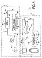
- FIG. 1 is a simplified block diagram illustrating an exemplary embodiment of a combined HVAC system constructed in accordance with the teachings of the present invention, wherein the heating and air conditioning system is in an air conditioning mode;
- FIG. 2 is a simplified block diagram illustrating the HVAC system of FIG. 1 in a heating mode
- FIG. 3 is a simplified block diagram of an alternative embodiment of an HVAC system in accordance with the present invention, illustrated in a cooling mode;
- FIG. 4 is a simplified block diagram illustrating the HVAC system of FIG. 3 in a heating mode.
- FIG. 1 illustrates a simplified block diagram of a preferred embodiment of a heating, ventilation and air conditioning system (HVAC system), indicated as a whole as 8, for heating, ventilating and cooling a passenger compartment of a vehicle, preferably a passenger compartment of a bus.
- HVAC system heating, ventilation and air conditioning system
- the HVAC system 8 utilizes a primary heating and air condition loop (hereinafter the primary loop), indicated as a whole as 10, that is assisted by a parallel secondary heating and cooling loop (hereinafter the secondary loop), indicated as a whole as 12.
- the primary loop 10 is a heating and air conditioning heat pump system utilizing a high pressure refrigerant process to either heat or cool the passenger compartment. A heat pump operates to transfer heat from one medium to another.
- the secondary loop 12 is a low pressure liquid system that selectively transfers heat from or to the primary loop 10.
- the primary loop 10 is a high pressure refrigerant heat pump system and in an exemplary embodiment includes a compressor 20, a reversing valve 22, a refrigerant-to-air heat exchanger 24, a refrigerant-to-liquid heat exchanger 26, first and second bypass valves 28 and 30, first and second refrigerant metering devices 32 and 34, and a first air movement device 36.
- the components of the primary loop 10 are operably coupled by, for example, tubing or suction line 38 to form the heat pump system that transfers heat energy from one location to another.
- the secondary loop 12 operates to selectively transfer heat energy from the primary loop 10 during the cooling mode and to the primary loop 10 during the heating mode (see FIG. 2 ). Heat is transferred between the primary and secondary loops 10 and 12 via the refrigerant-to-liquid heat exchanger 26. Therefore, the refrigerant-to-liquid heat exchanger 26 is a component of both the primary loop 10 and the secondary loop 12.
- the secondary loop 12 further includes a liquid pump 40, a liquid-to-air heat exchanger 42, a third bypass valve 44, a secondary heat source 46, a second air movement device 48 and a purge tank 50.
- the components of the secondary loop 12 are operably coupled by, for example, tubing or suction line, indicated as 52, to form a fluid circuit.
- FIG. 1 For ease of understanding, an embodiment of the invention and its components will be first described with reference to FIG. 1 in which the HVAC system 8 is in the air conditioning mode ("A/C mode") to cool the air in the passenger compartment of a vehicle. Then the description will describe operation in a heating mode with reference to FIG. 2 .
- A/C mode air conditioning mode
- the first and second refrigerant metering devices 32 and 34 are devices that permit a high-temperature, high-pressure liquid refrigerant (e.g., R-134a and other haloalkanes ) flowing through the primary loop 10 to be changed to a low temperature, low pressure liquid refrigerant.
- a high-temperature, high-pressure liquid refrigerant e.g., R-134a and other haloalkanes
- fluid passes only through the first refrigerant metering device 32 and bypasses the second refrigerant metering device 34 as it passes through bypass valve 28.
- the refrigerant metering devices 32, 34 are expansion valves, thermostatic expansion valves, and the like.
- the refrigerant-to-air heat exchanger 24 functions as an evaporator, and is disposed downstream of the first refrigerant metering device 32 (with respect to the flow of the refrigerant through the primary loop 10, indicated by arrows 58).
- the refrigerant-to-air heat exchanger 24 is a heat exchanging device that receives low temperature, low pressure liquid refrigerant from the first refrigerant metering device 32. While flowing through the refrigerant-to-air heat exchanger 24, the low temperature, low pressure liquid refrigerant absorbs latent heat from a medium, typically air, identified by arrows 60, that is circulated through the passenger compartment.
- the refrigerant-to-air heat exchanger 24 is positioned in fluid communication with the interior of the passenger compartment. Due to the absorption of heat from air 60, the low temperature, low pressure liquid refrigerant cools the air 60 and, undergoes a phase change by boiling into a low-temperature, low-pressure vapor refrigerant. To increase the efficiency of this heat exchanging process between the air and the refrigerant, in a preferred embodiment the refrigerant-to-air heat exchanger 24 is a coil.
- the first air movement device 36 is disposed proximate the refrigerant-to-air heat exchanger 24 and is configured to move and/or draw air 60 through the refrigerant-to-air heat exchanger 24. After passing through the refrigerant-to-air heat exchanger 24 and cooling, the cooled air is expelled into the passenger compartment of the vehicle.
- the first air movement device 36 is a fan such as, for example, an axial fan.
- the fan is preferably adjustable such that the amount of air passing through the refrigerant-to-air heat exchanger 24 is variable depending on the cooling needs of the passenger compartment.
- the air movement device 36 may draw a portion of fresh external air into the vehicle as well as circulate air from within the passenger compartment to provide ventilation of the vehicle.
- the compressor 20 compresses the low-pressure, low-temperature vapor refrigerant received and/or drawn from the evaporator, the refrigerant-to-air heat exchanger 24 in the A/C mode. During compression, the low-pressure, low-temperature vapor refrigerant changes to a high-temperature, high-pressure vapor refrigerant. The high-temperature, high-pressure vapor refrigerant passes from the compressor 20 to the condenser, the refrigerant-to-liquid heat exchanger 26 in the A/C mode.
- the compressor 20 is driven by an electric direct current motor.
- the compressor 20 is a variable speed motor-driven compressor. The motor may be driven by either direct current or alternating current electricity.
- the compressor, and consequently, the HVAC system 8 is well equipped to operate in the A/C mode as a no-idle, i.e. engine off, HVAC system 8.
- the no-idle control may be in accordance with U.S. Pat. No. 6,889,762 entitled "Vehicle Air Conditioning and Heating system Providing Engine on and Engine Off Operation" to Zeigler et al.
- the refrigerant-to-liquid heat exchanger 26 functions as a condenser and is disposed downstream of the compressor 20.
- the refrigerant-to-liquid heat exchanger 26 receives the high-temperature, high pressure vapor refrigerant from the compressor 20. While flowing through the refrigerant-to-liquid heat exchanger 26, the high-temperature, high-pressure vapor refrigerant dissipates heat to a second medium, which is a low-pressure, low-temperature liquid coolant, usually a liquid that is comparable to or is a liquid engine coolant such as antifreeze.
- a second medium which is a low-pressure, low-temperature liquid coolant, usually a liquid that is comparable to or is a liquid engine coolant such as antifreeze.
- the high-temperature, high-pressure vapor refrigerant undergoes a phase change by condensing into a high-temperature, high-pressure liquid refrigerant.
- Embodiments of the refrigerant-to-liquid heat exchanger 26 may include any type of refrigerant-to-liquid heat exchanger such as a parallel/counter flow heat exchanger, shell and tube heat exchanger, plate heat exchanger, and the like.
- the high-temperature, high-pressure liquid refrigerant After passing through the refrigerant-to-liquid heat exchanger 26, the high-temperature, high-pressure liquid refrigerant passes through the first bypass valve 28, which is parallel to the second refrigerant metering device 34. In an open condition, as illustrated in FIG. 1 , the first bypass valve 28 allows the high-temperature, high-pressure liquid refrigerant to bypass the second refrigerant metering device 34.
- the second bypass valve 30 which is in parallel with the first refrigerant metering device 32, is in a closed condition during the A/C mode and prevents the high-temperature, high-pressure liquid refrigerant from bypassing the first refrigerant metering device 32.
- the secondary loop 12 exhausts heat energy added to the refrigerant from the air in the passenger compartment as well as heat added by the compressor 20 as it converts the low-pressure low-temperature vapor refrigerant to a high-pressure high-temperature vapor refrigerant.
- the added heat is transferred from the refrigerant in the primary loop 10 to the liquid coolant in the secondary loop 12 via the refrigerant-to-liquid heat exchanger 26.
- the liquid coolant passing through the secondary loop 12 remains at a low pressure.
- the low-temperature liquid coolant upstream (with respect to the flow of the refrigerant through the secondary loop 12, indicated by arrows 68) from the refrigerant-to-liquid heat exchanger 26 passes through the refrigerant-to-liquid heat exchanger 26 while high-temperature, high-pressure vapor refrigerant of the primary loop 10 passes through the refrigerant-to-liquid heat exchanger 26.
- the refrigerant-to-liquid heat exchanger 26 heat energy dissipates from the high-temperature, high pressure vapor refrigerant and is absorbed by the low-temperature liquid coolant to allow the refrigerant to condense to a liquid refrigerant, as explained previously.
- the low-temperature liquid coolant absorbs heat from the primary loop 10, it exits the refrigerant-to-liquid heat exchanger 26 as a high-temperature liquid coolant.
- the liquid-to-air heat exchanger 42 is disposed downstream from the refrigerant-to-liquid heat exchanger 26 and is a heat exchanging device that receives the high-temperature liquid coolant from the refrigerant-to-liquid heat exchanger 26. While flowing through the liquid-to-air heat exchanger 42, the high-temperature liquid coolant dissipates heat to a medium in close proximity, which is usually air. Furthermore, this medium typically is in fluid communication with the exterior of the vehicle. Due to the dissipation of heat, the high-temperature liquid coolant becomes an intermediate-temperature liquid coolant and exits the liquid-to-air heat exchanger 42. To increase the efficiency of this heat exchanging process between the air and the liquid, in a preferred embodiment, the liquid-to-air heat exchanger 42 is a coil.
- the second air movement device 48 is disposed proximate the liquid-to-air heat exchanger 42 and is configured to move and/or draw air through the liquid-to-air heat exchanger 42.
- the second air movement device 48 is a fan such as, for example, an axial fan similar to that of the first air movement device 36.
- the liquid-to-air heat exchanger 42 is positioned such that air flowing relative to the vehicle as the vehicle is moving passes through the liquid-to-air heat exchanger 42 further promoting heat transfer from the high-temperature liquid coolant to the external surrounding air.
- the liquid-to-air heat exchanger 42 is mounted to the radiator of the vehicle and uses the air flow generated to cool the engine coolant to cool the high-temperature liquid coolant in the secondary loop 12.
- the intermediate-temperature liquid exiting the liquid-to-air heat exchanger 42 bypasses the secondary heat source 46 which is downstream from the liquid-to-air heat exchanger 42 to prevent unnecessary heat energy from entering the HVAC system 8.
- the intermediate-temperature liquid bypasses the secondary heat source 46 by passing through the third bypass valve 44, as indicated by arrow 70.
- the intermediate-temperature liquid coolant after passing through the third bypass valve 44, reenters and passes through a second portion of the liquid-to-air heat exchanger 42 that is downstream from the third bypass valve 44 and secondary heat source 46, to preferably dissipate additional heat energy.
- the intermediate-temperature liquid coolant exits the liquid-to-air heat exchanger as low-temperature liquid and passes to the liquid pump 40.
- the liquid coolant makes only a single pass through the liquid-to-air heat exchanger 42. After exiting the liquid-to-air heat exchanger 42, the cooled liquid coolant passes through the bypass valve 44 and through a bypass loop 71 to bypass the secondary heat source 46. After bypassing the secondary heat source 46, the liquid coolant passes to the liquid pump 40.
- the secondary heat source 46 is completely downstream from the liquid-to-air heat exchanger 42 rather than separating the liquid-to-air heat exchanger 42 into two separate portions, as in the embodiment illustrated in FIG. 1 .
- the liquid pump 40 draws and pumps the liquid through the secondary loop 12.
- the liquid pump 40 is disposed downstream from the liquid-to-air heat exchanger 42 and pumps the low-temperature liquid to a purge tank 50.
- the liquid pump 40 may be any type of fluid pump such as, for example, a centrifugal or reciprocating pump.
- the pump 40 is a low pressure pump such that the liquid circulating through the secondary loop 12 remains at a low pressure.
- the liquid pump 40 is driven by an electric variable speed motor.
- the HVAC system 8 is well equipped to operate as a no-idle, i.e. engine off, HVAC system 8.
- the purge tank 50 is disposed downstream of the liquid pump 40 and functions as a holding tank for the low-temperature liquid, during the A/C mode. It further functions to allow expansion and contraction of the liquid within the secondary loop 12 thereby allowing the liquid pump 40 to maintain the low-pressure and flow rate of the liquid circulating through the secondary loop 12. As the purge tank is the last component of the secondary loop, after the liquid enters the purge tank 50, the cycle is repeated.
- FIG. 2 is a simplified schematic illustration of the HVAC system 8 of an embodiment of the present invention in the heating mode.
- the primary loop 10 dissipates heat energy to the air in the passenger compartment of the vehicle rather than to the secondary loop 12.
- the HVAC system 8 switches from the A/C mode to the heating mode by manipulating the previously identified bypass valves 28, 30, and 44 and the reversing valve 22. The heating process will be further described below with reference to FIG. 2 .
- the secondary loop 12 transfers heat energy from the secondary heat source 46 to the primary loop 10, which allows the HVAC system to be run in the heat mode at lower ambient temperatures by providing a heat load to the primary loop.
- a heat pump operates to transfer heat from one medium to another.
- the heat pump must draw heat from a medium external to the vehicle to allow the refrigerant cycle to operate and to then transfer the heat energy to the passenger compartment.
- the external medium is typically very cold (i.e. below freezing). It is difficult and less efficient to draw heat from a medium that has low quantities of heat. Thus, drawing heat energy from cold medium (i.e. a low ambient temperature) would cause the heat pump to operate less efficiently.
- the evaporator becomes very cold and when the evaporator is a refrigerant-to-air heat exchanger, as would be the case if the secondary loop 12 were not present, humidity in the air causes the heat exchanger, which would be exposed to the cold ambient air, to ice over.
- the heat pump typically must be operated in reverse (i.e. in the A/C mode) to melt the ice on the heat exchanger. This is highly inefficient because none of the energy being used to run the circuit in this direction would be used to heat the passenger compartment of the vehicle.
- a secondary deicing mechanism such as a fuel fired heater or electricity resistive heater must be provided.
- the refrigerant-to-liquid heat exchanger 26 is not as susceptible to ice over because heat transfer into the primary loop 8 occurs internal to the heat exchanger 26 and at higher temperatures, and in some embodiments within the vehicle.
- the secondary loop 12 allows the secondary heat source 46 to be positioned remote from the refrigerant-to-liquid heat exchanger 26.
- the primary loop 10 includes a reversing valve 22.
- the reversing valve 22 switches the heat exchanger that supplies low-temperature, low-pressure vapor refrigerant to the compressor 20 and which heat exchanger receives the high-temperature, high-pressure vapor refrigerant from the compressor 20.
- the refrigerant-to-air heat exchanger 24 of the primary loop 10 becomes the condenser and the refrigerant-to-liquid heat exchanger 26 becomes the evaporator.
- the second bypass valve 32 opens allowing high-temperature, high-pressure liquid refrigerant exiting the refrigerant-to-air heat exchanger (the condenser) 24 to bypass the first refrigerant metering device 32.
- the first bypass valve 28 closes causing the high-temperature, high-pressure liquid refrigerant to pass through the second refrigerant metering device 34 and changing to a low-temperature, low-pressure liquid refrigerant, as explained previously with reference to the A/C mode.
- low-temperature, low-pressure liquid refrigerant passes through the refrigerant-to-liquid heat exchanger 26 to absorb heat energy from a high-temperature liquid coolant flowing through the secondary loop 12, as will be more fully explained below.
- This heat energy drawn from the secondary loop 12 will be dissipated to the air in the passenger compartment when high-temperature, high-pressure vapor refrigerant passes through the refrigerant-to-air heat exchanger 24.
- the primary loop 10 operates in reverse. In this mode, energy is transferred from the secondary loop 12 to the primary loop 10 and dissipated to the passenger compartment.
- the flow of liquid coolant through the secondary loop 12, indicated as arrows 68, does not reverse.
- the low-pressure liquid passing through the secondary loop 12 acquires heat from the secondary heat source 46 and functions to transfer this heat energy to the primary loop 10 via the refrigerant-to-liquid heat exchanger 26, as explained previously.
- the low-pressure liquid coolant of the secondary loop 12 entering the refrigerant-to-liquid heat exchanger 26 is a high-temperature liquid coolant.
- the high temperature liquid coolant dissipates heat energy to the low-temperature, low-pressure refrigerant of the primary loop 10.
- the heat energy dissipated from the secondary loop 12 is absorbed by the refrigerant in the primary loop 10 and subsequently dissipated to the air in the passenger compartment.
- the liquid coolant passes through the liquid-to-air heat exchanger 42 and dissipates additional heat energy from the liquid coolant to the air passing through the heat exchanger 42.
- the liquid coolant passes through the secondary heat source 46.
- the bypass valve 44 is positioned so that the liquid coolant flows to the secondary heat source 46 rather than bypassing it as in the A/C mode. As the liquid coolant passes through the secondary heat source 46, it absorbs heat energy.
- the secondary heat source 46 is the engine of the vehicle. It is a benefit of the HVAC system 8 that the heating system may be used to reduce the load on the engine cooling system as it is running by dissipating some of the waste heat generated by the operating engine to the passenger compartment.
- the secondary heat source 46 is a fuel fired heat source that burns fuel to produce heat energy.
- a fuel fired heat source is more environmentally friendly and efficient than running a large diesel engine to provide a heat source when the full power of the primary engine of the vehicle is not required (i.e. during resting or other stationary situations).
- the secondary heat source is a electricity resistive heater that uses electrical resistance to convert electricity to heat energy. This embodiment would be beneficial when the vehicle would typically have access to a secondary electricity supply, such as shore power.
- the engine of the vehicle can function as the secondary heat source after it is deactivated because it will remain warm for an extended period of time after it has been shut-off.
- the configuration of having a secondary loop 12 allows the secondary heat source 46 which facilitates operating the primary loop 10 in the heating mode during colder weather to be positioned remote from the refrigerant-to-liquid heat exchanger 26 without requiring long refrigerant lines.
- the liquid coolant does not bypass the secondary heat source 46.
- the bypass valve 44 is positioned such that the liquid coolant that exits the liquid-to-air heat exchanger 42, which in this embodiment is low-temperature liquid coolant, passes through the secondary heat source 46 and becomes a high-temperature liquid coolant.
- the high-temperature liquid coolant only passes through the liquid-to-air heat exchanger 42 one time. This is preferable because no heat is dissipated from the high temperature liquid coolant by passing through the liquid-to-air heat exchanger 42.
- the liquid coolant After the liquid coolant has passed through the secondary heat source 46 and becomes high-temperature coolant, it is pumped through the refrigerant-to-liquid heat exchanger 26 where the heat energy is transferred from the high-temperature liquid coolant of the secondary loop 12 to the low-temperature, low-pressure refrigerant of the primary loop 10.
- the HVAC system when the HVAC system as described above is used in large passenger vehicles, for example buses, multiple primary loops 10 may be installed in the vehicle such that more configurable localized heating and air conditioning can be achieved.
- the primary loop may be a modular, self-contained unit adapted to be connected to the secondary loop. Specifically, one unit may be installed to condition the air in the back of the vehicle while another unit may be installed near the front of the vehicle to condition the front of the passenger compartment.
- the HVAC system may include a single secondary loop coupled to the plurality of primary loops or separate secondary loops coupled to each individual primary loop.
- the secondary loop 8 may be coupled to the refrigerant-to-liquid heat exchanger 26 with removable couplings.
Abstract
Description
- This invention generally relates to air conditioning systems. More particularly, this invention relates to vehicle mounted air conditioning systems for over the road vehicles.
- In today's fast-paced, on-the-move society, buses are used to transport a large number of people from location to location. Bus manufacturers have continued to increase their emphasis on ergonomic factors in the design and manufacture of their vehicles.
Indeed, the passenger compartment of a modem bus contains many features to improve the passenger's comfort. These features include, for example, audio and video systems, improved seats, including variable position seating, lumbar supports in the seats, increased sound insulation, and heating, ventilation, and air conditioning systems (HVAC systems) that provide a comfortable environment for a large quantity of passengers. - To condition the air of the passenger compartment, many of the HVAC systems in buses employ a heating system separate from the cooling system. Many heating systems use heat generated from the engine of the bus to heat the passenger compartment. Unfortunately, this requires the engine to be running or turned on and off to heat the passenger compartment. The cooling system typically uses a high-pressure refrigerant system. Many of these refrigerant systems have engine-belt driven compressors. While these engine-belt driven compressors are well-suited to circulate and pump refrigerant through the refrigerant system while the engine is running, they are not able to operate when the engine is turned off. As a result, the cooling system cannot cool the passenger compartment unless the engine of the bus is left running.
- Unfortunately, leaving the engine running simply to condition the air in the passenger compartment wastes money and increases the pollution produced over the life of the bus. This is particularly relevant to buses because buses may be occupied while not moving for extended periods of time, such as when the bus is waiting for passengers to load the bus, specifically when the bus is waiting for the passengers to exit an event.
- To address this problem with other vehicles such as over-the-road trucks, the newest trucks are manufactured with no-idle heating and air conditioning systems. The no-idle heating and air conditioning systems are able to provide cooling and/or heating of the passenger compartment when the engine of the vehicle is turned off. Such no-idle heating and air conditioning units typically use a high pressure refrigerant system with an electric powered, motor-driven, variable speed compressor powered by one or more batteries, shore power and the like instead of the primary engine belt. By using a motor-driven compressor, the no-idle heating and air conditioning system is able to heat and/or cool the passenger compartment even when the engine in the vehicle is turned off.
- Unfortunately, while in the engine off condition, some no-idle systems are not capable of providing both heating as well as cooling using a single circuit. These systems require a second system to provide a heat source during the engine off condition, typically utilizing a fuel fired heater. Unfortunately, this increases the amount of space required for the entire HVAC system.
- Another problem with standard cooling systems that these high pressure refrigerant systems use couplings which makes the system prone to leaks. Further, because the refrigeration system is not closed until assembly of the vehicle takes place within the manufacturing assembly facility, the use of this type of system further burdens the assembly manufacturer by requiring that the initial purging and charging of the refrigeration system take place within the assembly plant of the vehicle itself increasing the manufacturer's costs to manufacture the vehicle and requiring the manufacturer to maintain and store a high quantity of refrigerant.
- Thus, it would be appreciated in the art if a HVAC system for a vehicle could have a system that provides both heating and cooling functions without requiring the engine to be running, that is more efficient, that reduces the likelihood of leaks in the high-pressure refrigerant.
- In view of the above, it is an object of an embodiment of the present invention to provide a new and improved heating and air condition system for the passenger compartment of a vehicle. More particularly, it is an aspect of an embodiment of the present invention to provide a new and improved heating and air conditioning system that provides heating and cooling of the vehicle in an engine on and in an engine off condition
- In an embodiment of the present invention, the heating and air conditioning system includes a primary loop and a secondary loop thermally connected to one another by a common heat exchanger. The primary and secondary loops pass heat energy between one another in a direction depending on if the system is in a heating mode or a cooling mode.
- In addition to including the common heat exchanger, one embodiment includes a primary loop that comprises another heat exchanger, a refrigerant compressor, a plurality of valves, a plurality of refrigerant metering devices and a flow reversing valve. The secondary loop generally includes, in addition to the common heat exchanger, another heat exchanger, a liquid pump, a secondary heat source, and a circuit for selectively bypassing the secondary heat source.
- In an embodiment, the primary loop is a high pressure refrigerant loop and the secondary loop is a low pressure liquid loop.
- In an embodiment, the primary loop is a heat pump such that it may function to provide both cooling and heating of the passenger compartment of the vehicle by reversing the flow of the refrigerant through the primary loop. In this embodiment, the secondary loop preferably passes through the secondary heat source during heating and bypasses the secondary heat source during cooling.
- In yet a further embodiment of the present invention, the secondary heat source is remote from the primary loop and may include the engine of the vehicle, a fuel fired heater, or an electric heater. The secondary heat source functions to add heat energy to the primary loop during a heating mode to increase the efficiency of the heating mode of the primary loop.
- In a further embodiment, the liquid pump and the refrigerant compressor are electrically driven. This allows the heating and air conditioning system of an embodiment of the present invention to function as a no-idle system.
- Other aspects, objectives and advantages of the invention will become more apparent from the following detailed description when taken in conjunction with the accompanying drawings.
- The accompanying drawings incorporated in and forming a part of the specification illustrate several aspects of the present invention and, together with the description, serve to explain the principles of the invention. In the drawings:
-
FIG. 1 is a simplified block diagram illustrating an exemplary embodiment of a combined HVAC system constructed in accordance with the teachings of the present invention, wherein the heating and air conditioning system is in an air conditioning mode; -
FIG. 2 is a simplified block diagram illustrating the HVAC system ofFIG. 1 in a heating mode; -
FIG. 3 is a simplified block diagram of an alternative embodiment of an HVAC system in accordance with the present invention, illustrated in a cooling mode; and -
FIG. 4 is a simplified block diagram illustrating the HVAC system ofFIG. 3 in a heating mode. - While the invention will be described in connection with certain preferred embodiments, there is no intent to limit it to those embodiments. On the contrary, the intent is to cover all alternatives, modifications and equivalents as included within the scope of the invention as defined by the appended claims.
-
FIG. 1 illustrates a simplified block diagram of a preferred embodiment of a heating, ventilation and air conditioning system (HVAC system), indicated as a whole as 8, for heating, ventilating and cooling a passenger compartment of a vehicle, preferably a passenger compartment of a bus. For the heating and cooling functions, theHVAC system 8 utilizes a primary heating and air condition loop (hereinafter the primary loop), indicated as a whole as 10, that is assisted by a parallel secondary heating and cooling loop (hereinafter the secondary loop), indicated as a whole as 12. Theprimary loop 10 is a heating and air conditioning heat pump system utilizing a high pressure refrigerant process to either heat or cool the passenger compartment. A heat pump operates to transfer heat from one medium to another. Thesecondary loop 12 is a low pressure liquid system that selectively transfers heat from or to theprimary loop 10. - The
primary loop 10 is a high pressure refrigerant heat pump system and in an exemplary embodiment includes acompressor 20, areversing valve 22, a refrigerant-to-air heat exchanger 24, a refrigerant-to-liquid heat exchanger 26, first andsecond bypass valves refrigerant metering devices air movement device 36. The components of theprimary loop 10 are operably coupled by, for example, tubing orsuction line 38 to form the heat pump system that transfers heat energy from one location to another. - The
secondary loop 12 operates to selectively transfer heat energy from theprimary loop 10 during the cooling mode and to theprimary loop 10 during the heating mode (seeFIG. 2 ). Heat is transferred between the primary andsecondary loops liquid heat exchanger 26. Therefore, the refrigerant-to-liquid heat exchanger 26 is a component of both theprimary loop 10 and thesecondary loop 12. Thesecondary loop 12 further includes aliquid pump 40, a liquid-to-air heat exchanger 42, athird bypass valve 44, asecondary heat source 46, a secondair movement device 48 and apurge tank 50. The components of thesecondary loop 12 are operably coupled by, for example, tubing or suction line, indicated as 52, to form a fluid circuit. - For ease of understanding, an embodiment of the invention and its components will be first described with reference to
FIG. 1 in which theHVAC system 8 is in the air conditioning mode ("A/C mode") to cool the air in the passenger compartment of a vehicle. Then the description will describe operation in a heating mode with reference toFIG. 2 . - Beginning with the
primary loop 10, the first and secondrefrigerant metering devices primary loop 10 to be changed to a low temperature, low pressure liquid refrigerant. During the A/C mode, fluid passes only through the firstrefrigerant metering device 32 and bypasses the secondrefrigerant metering device 34 as it passes throughbypass valve 28. In a preferred embodiment, therefrigerant metering devices - In the A/C mode, the refrigerant-to-
air heat exchanger 24, functions as an evaporator, and is disposed downstream of the first refrigerant metering device 32 (with respect to the flow of the refrigerant through theprimary loop 10, indicated by arrows 58). The refrigerant-to-air heat exchanger 24 is a heat exchanging device that receives low temperature, low pressure liquid refrigerant from the firstrefrigerant metering device 32. While flowing through the refrigerant-to-air heat exchanger 24, the low temperature, low pressure liquid refrigerant absorbs latent heat from a medium, typically air, identified by arrows 60, that is circulated through the passenger compartment. As such the refrigerant-to-air heat exchanger 24 is positioned in fluid communication with the interior of the passenger compartment. Due to the absorption of heat from air 60, the low temperature, low pressure liquid refrigerant cools the air 60 and, undergoes a phase change by boiling into a low-temperature, low-pressure vapor refrigerant. To increase the efficiency of this heat exchanging process between the air and the refrigerant, in a preferred embodiment the refrigerant-to-air heat exchanger 24 is a coil. - The first
air movement device 36 is disposed proximate the refrigerant-to-air heat exchanger 24 and is configured to move and/or draw air 60 through the refrigerant-to-air heat exchanger 24. After passing through the refrigerant-to-air heat exchanger 24 and cooling, the cooled air is expelled into the passenger compartment of the vehicle. In a preferred embodiment, the firstair movement device 36 is a fan such as, for example, an axial fan. Furthermore, the fan is preferably adjustable such that the amount of air passing through the refrigerant-to-air heat exchanger 24 is variable depending on the cooling needs of the passenger compartment. In another embodiment, theair movement device 36 may draw a portion of fresh external air into the vehicle as well as circulate air from within the passenger compartment to provide ventilation of the vehicle. - The
compressor 20 compresses the low-pressure, low-temperature vapor refrigerant received and/or drawn from the evaporator, the refrigerant-to-air heat exchanger 24 in the A/C mode. During compression, the low-pressure, low-temperature vapor refrigerant changes to a high-temperature, high-pressure vapor refrigerant. The high-temperature, high-pressure vapor refrigerant passes from thecompressor 20 to the condenser, the refrigerant-to-liquid heat exchanger 26 in the A/C mode. In a preferred embodiment, thecompressor 20 is driven by an electric direct current motor. In an exemplary embodiment, thecompressor 20 is a variable speed motor-driven compressor. The motor may be driven by either direct current or alternating current electricity. As such, the compressor, and consequently, theHVAC system 8 is well equipped to operate in the A/C mode as a no-idle, i.e. engine off,HVAC system 8. The no-idle control may be in accordance withU.S. Pat. No. 6,889,762 entitled "Vehicle Air Conditioning and Heating system Providing Engine on and Engine Off Operation" to Zeigler et al. - In the A/C mode, the refrigerant-to-
liquid heat exchanger 26 functions as a condenser and is disposed downstream of thecompressor 20. The refrigerant-to-liquid heat exchanger 26 receives the high-temperature, high pressure vapor refrigerant from thecompressor 20. While flowing through the refrigerant-to-liquid heat exchanger 26, the high-temperature, high-pressure vapor refrigerant dissipates heat to a second medium, which is a low-pressure, low-temperature liquid coolant, usually a liquid that is comparable to or is a liquid engine coolant such as antifreeze. As the heat is dissipated into the second medium, the high-temperature, high-pressure vapor refrigerant undergoes a phase change by condensing into a high-temperature, high-pressure liquid refrigerant. Embodiments of the refrigerant-to-liquid heat exchanger 26 may include any type of refrigerant-to-liquid heat exchanger such as a parallel/counter flow heat exchanger, shell and tube heat exchanger, plate heat exchanger, and the like. - After passing through the refrigerant-to-
liquid heat exchanger 26, the high-temperature, high-pressure liquid refrigerant passes through thefirst bypass valve 28, which is parallel to the secondrefrigerant metering device 34. In an open condition, as illustrated inFIG. 1 , thefirst bypass valve 28 allows the high-temperature, high-pressure liquid refrigerant to bypass the secondrefrigerant metering device 34. - After passing through the
first bypass valve 28, the high-temperature, high-pressure liquid refrigerant returns to the firstrefrigerant metering device 32 and the cycle is repeated. Thesecond bypass valve 30, which is in parallel with the firstrefrigerant metering device 32, is in a closed condition during the A/C mode and prevents the high-temperature, high-pressure liquid refrigerant from bypassing the firstrefrigerant metering device 32. - During the A/C mode, the
secondary loop 12 exhausts heat energy added to the refrigerant from the air in the passenger compartment as well as heat added by thecompressor 20 as it converts the low-pressure low-temperature vapor refrigerant to a high-pressure high-temperature vapor refrigerant. Particularly, the added heat is transferred from the refrigerant in theprimary loop 10 to the liquid coolant in thesecondary loop 12 via the refrigerant-to-liquid heat exchanger 26. - The liquid coolant passing through the
secondary loop 12 remains at a low pressure. The low-temperature liquid coolant upstream (with respect to the flow of the refrigerant through thesecondary loop 12, indicated by arrows 68) from the refrigerant-to-liquid heat exchanger 26 passes through the refrigerant-to-liquid heat exchanger 26 while high-temperature, high-pressure vapor refrigerant of theprimary loop 10 passes through the refrigerant-to-liquid heat exchanger 26. As the two fluids pass through the refrigerant-to-liquid heat exchanger 26, heat energy dissipates from the high-temperature, high pressure vapor refrigerant and is absorbed by the low-temperature liquid coolant to allow the refrigerant to condense to a liquid refrigerant, as explained previously. After the low-temperature liquid coolant absorbs heat from theprimary loop 10, it exits the refrigerant-to-liquid heat exchanger 26 as a high-temperature liquid coolant. - The liquid-to-
air heat exchanger 42 is disposed downstream from the refrigerant-to-liquid heat exchanger 26 and is a heat exchanging device that receives the high-temperature liquid coolant from the refrigerant-to-liquid heat exchanger 26. While flowing through the liquid-to-air heat exchanger 42, the high-temperature liquid coolant dissipates heat to a medium in close proximity, which is usually air. Furthermore, this medium typically is in fluid communication with the exterior of the vehicle. Due to the dissipation of heat, the high-temperature liquid coolant becomes an intermediate-temperature liquid coolant and exits the liquid-to-air heat exchanger 42. To increase the efficiency of this heat exchanging process between the air and the liquid, in a preferred embodiment, the liquid-to-air heat exchanger 42 is a coil. - In an embodiment, to further improve the efficiency, the second
air movement device 48 is disposed proximate the liquid-to-air heat exchanger 42 and is configured to move and/or draw air through the liquid-to-air heat exchanger 42. In a preferred embodiment, the secondair movement device 48 is a fan such as, for example, an axial fan similar to that of the firstair movement device 36. In a further embodiment, the liquid-to-air heat exchanger 42 is positioned such that air flowing relative to the vehicle as the vehicle is moving passes through the liquid-to-air heat exchanger 42 further promoting heat transfer from the high-temperature liquid coolant to the external surrounding air. And in an even further embodiment, the liquid-to-air heat exchanger 42 is mounted to the radiator of the vehicle and uses the air flow generated to cool the engine coolant to cool the high-temperature liquid coolant in thesecondary loop 12. - During the A/C mode, the intermediate-temperature liquid exiting the liquid-to-
air heat exchanger 42 bypasses thesecondary heat source 46 which is downstream from the liquid-to-air heat exchanger 42 to prevent unnecessary heat energy from entering theHVAC system 8. The intermediate-temperature liquid bypasses thesecondary heat source 46 by passing through thethird bypass valve 44, as indicated byarrow 70. - In an embodiment, after passing through the
third bypass valve 44, the intermediate-temperature liquid coolant reenters and passes through a second portion of the liquid-to-air heat exchanger 42 that is downstream from thethird bypass valve 44 andsecondary heat source 46, to preferably dissipate additional heat energy. The intermediate-temperature liquid coolant exits the liquid-to-air heat exchanger as low-temperature liquid and passes to theliquid pump 40. - In an alternative embodiment, as illustrated in
FIG. 3 , the liquid coolant makes only a single pass through the liquid-to-air heat exchanger 42. After exiting the liquid-to-air heat exchanger 42, the cooled liquid coolant passes through thebypass valve 44 and through abypass loop 71 to bypass thesecondary heat source 46. After bypassing thesecondary heat source 46, the liquid coolant passes to theliquid pump 40. In this embodiment, thesecondary heat source 46 is completely downstream from the liquid-to-air heat exchanger 42 rather than separating the liquid-to-air heat exchanger 42 into two separate portions, as in the embodiment illustrated inFIG. 1 . - Returning to
FIG. 1 , theliquid pump 40 draws and pumps the liquid through thesecondary loop 12. Theliquid pump 40 is disposed downstream from the liquid-to-air heat exchanger 42 and pumps the low-temperature liquid to apurge tank 50. Theliquid pump 40 may be any type of fluid pump such as, for example, a centrifugal or reciprocating pump. Further, thepump 40 is a low pressure pump such that the liquid circulating through thesecondary loop 12 remains at a low pressure. In an exemplary embodiment, theliquid pump 40 is driven by an electric variable speed motor. As such, theHVAC system 8 is well equipped to operate as a no-idle, i.e. engine off,HVAC system 8. - The
purge tank 50 is disposed downstream of theliquid pump 40 and functions as a holding tank for the low-temperature liquid, during the A/C mode. It further functions to allow expansion and contraction of the liquid within thesecondary loop 12 thereby allowing theliquid pump 40 to maintain the low-pressure and flow rate of the liquid circulating through thesecondary loop 12. As the purge tank is the last component of the secondary loop, after the liquid enters thepurge tank 50, the cycle is repeated. -
FIG. 2 is a simplified schematic illustration of theHVAC system 8 of an embodiment of the present invention in the heating mode. During the heating mode, theprimary loop 10 dissipates heat energy to the air in the passenger compartment of the vehicle rather than to thesecondary loop 12. TheHVAC system 8 switches from the A/C mode to the heating mode by manipulating the previously identifiedbypass valves valve 22. The heating process will be further described below with reference toFIG. 2 . - The
secondary loop 12 transfers heat energy from thesecondary heat source 46 to theprimary loop 10, which allows the HVAC system to be run in the heat mode at lower ambient temperatures by providing a heat load to the primary loop. As indicated previously, a heat pump operates to transfer heat from one medium to another. In a single loop heat pump, the heat pump must draw heat from a medium external to the vehicle to allow the refrigerant cycle to operate and to then transfer the heat energy to the passenger compartment. However, when the heating mode is required, the external medium is typically very cold (i.e. below freezing). It is difficult and less efficient to draw heat from a medium that has low quantities of heat. Thus, drawing heat energy from cold medium (i.e. a low ambient temperature) would cause the heat pump to operate less efficiently. - Second, during the heating cycle of a heat pump, the evaporator becomes very cold and when the evaporator is a refrigerant-to-air heat exchanger, as would be the case if the
secondary loop 12 were not present, humidity in the air causes the heat exchanger, which would be exposed to the cold ambient air, to ice over. To remove the ice from the heat exchanger (evaporator) the heat pump (primary loop) typically must be operated in reverse (i.e. in the A/C mode) to melt the ice on the heat exchanger. This is highly inefficient because none of the energy being used to run the circuit in this direction would be used to heat the passenger compartment of the vehicle. Alternatively, a secondary deicing mechanism such as a fuel fired heater or electricity resistive heater must be provided. The refrigerant-to-liquid heat exchanger 26 is not as susceptible to ice over because heat transfer into theprimary loop 8 occurs internal to theheat exchanger 26 and at higher temperatures, and in some embodiments within the vehicle. Thesecondary loop 12 allows thesecondary heat source 46 to be positioned remote from the refrigerant-to-liquid heat exchanger 26. - During the heating mode, the flow of refrigerant through the
primary loop 10, indicated byarrows 78, is reversed. To reverse the flow of refrigerant, theprimary loop 10 includes a reversingvalve 22. The reversingvalve 22 switches the heat exchanger that supplies low-temperature, low-pressure vapor refrigerant to thecompressor 20 and which heat exchanger receives the high-temperature, high-pressure vapor refrigerant from thecompressor 20. In other words, by reversing the refrigerant flow through theprimary loop 10, the refrigerant-to-air heat exchanger 24 of theprimary loop 10 becomes the condenser and the refrigerant-to-liquid heat exchanger 26 becomes the evaporator. - To facilitate the reversed flow of refrigerant, the
second bypass valve 32 opens allowing high-temperature, high-pressure liquid refrigerant exiting the refrigerant-to-air heat exchanger (the condenser) 24 to bypass the firstrefrigerant metering device 32. Thefirst bypass valve 28 closes causing the high-temperature, high-pressure liquid refrigerant to pass through the secondrefrigerant metering device 34 and changing to a low-temperature, low-pressure liquid refrigerant, as explained previously with reference to the A/C mode. - In this mode, low-temperature, low-pressure liquid refrigerant passes through the refrigerant-to-
liquid heat exchanger 26 to absorb heat energy from a high-temperature liquid coolant flowing through thesecondary loop 12, as will be more fully explained below. This heat energy drawn from thesecondary loop 12 will be dissipated to the air in the passenger compartment when high-temperature, high-pressure vapor refrigerant passes through the refrigerant-to-air heat exchanger 24. Thus, during the heating mode, theprimary loop 10 operates in reverse. In this mode, energy is transferred from thesecondary loop 12 to theprimary loop 10 and dissipated to the passenger compartment. - During the heating mode, the flow of liquid coolant through the
secondary loop 12, indicated asarrows 68, does not reverse. However, the low-pressure liquid passing through thesecondary loop 12 acquires heat from thesecondary heat source 46 and functions to transfer this heat energy to theprimary loop 10 via the refrigerant-to-liquid heat exchanger 26, as explained previously. - In the heating mode, the low-pressure liquid coolant of the
secondary loop 12 entering the refrigerant-to-liquid heat exchanger 26 is a high-temperature liquid coolant. As it passes through the refrigerant-to-liquid heat exchanger 26, the high temperature liquid coolant dissipates heat energy to the low-temperature, low-pressure refrigerant of theprimary loop 10. The heat energy dissipated from thesecondary loop 12 is absorbed by the refrigerant in theprimary loop 10 and subsequently dissipated to the air in the passenger compartment. - In the illustrated embodiment in
FIG. 2 , the liquid coolant passes through the liquid-to-air heat exchanger 42 and dissipates additional heat energy from the liquid coolant to the air passing through theheat exchanger 42. After passing through the liquid-to-air heat exchanger 42, the liquid coolant passes through thesecondary heat source 46. As such, thebypass valve 44 is positioned so that the liquid coolant flows to thesecondary heat source 46 rather than bypassing it as in the A/C mode. As the liquid coolant passes through thesecondary heat source 46, it absorbs heat energy. - In an embodiment, the
secondary heat source 46 is the engine of the vehicle. It is a benefit of theHVAC system 8 that the heating system may be used to reduce the load on the engine cooling system as it is running by dissipating some of the waste heat generated by the operating engine to the passenger compartment. - In an alternative embodiment, to promote engine-off or no-idle operation of the
HVAC system 8, thesecondary heat source 46 is a fuel fired heat source that burns fuel to produce heat energy. A fuel fired heat source is more environmentally friendly and efficient than running a large diesel engine to provide a heat source when the full power of the primary engine of the vehicle is not required (i.e. during resting or other stationary situations). In another embodiment, the secondary heat source is a electricity resistive heater that uses electrical resistance to convert electricity to heat energy. This embodiment would be beneficial when the vehicle would typically have access to a secondary electricity supply, such as shore power. However, it should be noted that the engine of the vehicle can function as the secondary heat source after it is deactivated because it will remain warm for an extended period of time after it has been shut-off. - Furthermore, the configuration of having a
secondary loop 12 allows thesecondary heat source 46 which facilitates operating theprimary loop 10 in the heating mode during colder weather to be positioned remote from the refrigerant-to-liquid heat exchanger 26 without requiring long refrigerant lines. - In the alternative embodiment described and illustrated above with reference to
FIG. 3 , during the heat mode illustrated inFIG. 4 , the liquid coolant does not bypass thesecondary heat source 46. In the heat mode, thebypass valve 44 is positioned such that the liquid coolant that exits the liquid-to-air heat exchanger 42, which in this embodiment is low-temperature liquid coolant, passes through thesecondary heat source 46 and becomes a high-temperature liquid coolant. The high-temperature liquid coolant only passes through the liquid-to-air heat exchanger 42 one time. This is preferable because no heat is dissipated from the high temperature liquid coolant by passing through the liquid-to-air heat exchanger 42. - After the liquid coolant has passed through the
secondary heat source 46 and becomes high-temperature coolant, it is pumped through the refrigerant-to-liquid heat exchanger 26 where the heat energy is transferred from the high-temperature liquid coolant of thesecondary loop 12 to the low-temperature, low-pressure refrigerant of theprimary loop 10. - It is contemplated that when the HVAC system as described above is used in large passenger vehicles, for example buses, multiple
primary loops 10 may be installed in the vehicle such that more configurable localized heating and air conditioning can be achieved. To facilitate this, the primary loop may be a modular, self-contained unit adapted to be connected to the secondary loop. Specifically, one unit may be installed to condition the air in the back of the vehicle while another unit may be installed near the front of the vehicle to condition the front of the passenger compartment. In these multiple primary loop systems, the HVAC system may include a single secondary loop coupled to the plurality of primary loops or separate secondary loops coupled to each individual primary loop. - The
secondary loop 8 may be coupled to the refrigerant-to-liquid heat exchanger 26 with removable couplings. - The use of the terms "a" and "an" and "the" and similar referents in the context of describing the invention (especially in the context of the following claims) is to be construed to cover both the singular and the plural, unless otherwise indicated herein or clearly contradicted by context. The terms "comprising", "having", "including", and "containing" are to be construed as open-ended terms (i.e., meaning "including, but not limited to,") unless otherwise noted. Recitation of ranges of values herein are merely intended to serve as a shorthand method of referring individually to each separate value falling within the range, unless otherwise indicated herein, and each separate value is incorporated into the specification as if it were individually recited herein. All methods described herein can be performed in any suitable order unless otherwise indicated herein or otherwise clearly contradicted by context. The use of any and all examples, or exemplary language (e.g., "such as") provided herein, is intended merely to better illuminate the invention and does not pose a limitation on the scope of the invention unless otherwise claimed. No language in the specification should be construed as indicating any non-claimed element as essential to the practice of the invention.
- Preferred embodiments of this invention are described herein, including the best mode known to the inventors for carrying out the invention. Variations of those preferred embodiments may become apparent to those of ordinary skill in the art upon reading the foregoing description. The inventors expect skilled artisans to employ such variations as appropriate, and the inventors intend for the invention to be practiced otherwise than as specifically described herein. Accordingly, this invention includes all modifications and equivalents of the subject matter recited in the claims appended hereto as permitted by applicable law. Moreover, any combination of the above-described elements in all possible variations thereof is encompassed by the invention unless otherwise indicated herein or otherwise clearly contradicted by context.
Claims (15)
- A heating and air conditioning system for a passenger compartment of a vehicle, comprising:a first heat exchanger (26);a primary loop (10) passing through the first heat exchanger and further comprising a compressor (20), a second heat exchanger (24), a flow reversing means (22) for reversing the fluid flow through the primary loop (10), and a first refrigerant metering device (32);a secondary loop (12) passing through the first heat exchanger (26) and further comprising a liquid pump (40), a third heat exchanger (42), a secondary heat source (46), and a bypass means (44) for selectively bypassing the secondary heat source (46); andwherein the secondary loop (12) is thermally coupled to the primary loop (10) by the first heat exchanger (26) and the second heat exchanger (24) is thermally coupled to an interior of the passenger compartment.
- The heating and air conditioning system of claim 1, wherein the secondary heat source (46) is the engine of the vehicle.
- The heating and air conditioning system of claim 1, wherein the secondary heat source (46) is a fuel fired heater or an electrically resistive heater.
- The heating and air conditioning system of any preceding claim, wherein the secondary heat source (46) and the third heat exchanger (42) are remote from the primary loop (10) and the passenger compartment of the vehicle.
- The heating and air conditioning system of any preceding claim, wherein the first heat exchanger (26) is a refrigerant-to-liquid heat exchanger, the second heat exchanger (24) is a refrigerant-to-air heat exchanger, and the third heat exchanger (42) is a liquid-to-air heat exchanger.
- The heating and air conditioning system of any preceding claim, wherein the compressor (20) is a direct current motor-driven compressor.
- The heating and air conditioning system of any preceding claim, wherein the primary loop (10) is a high-pressure refrigerant based circuit and the secondary loop (12) is a low-pressure coolant circuit.
- The heating and air conditioning system of claim 7, wherein the compressor 20, first and second heat exchangers (26,24), flow reversing means (22) and first refrigerant metering device (32) are coupled by fixed connections (38).
- The heating and air conditioning system of claim 8, wherein the primary loop (10) is a modular self-contained unit connected to the secondary loop (12).
- The heating and air conditioning system of any preceding claim, wherein during a heating mode liquid in the secondary loop (12) passes through the secondary heat source (46) and the flow reversing means (22) directs refrigerant from the first heat exchanger (26) to the compressor (20) and refrigerant from the compressor (20) to the second heat exchanger (24) and during a cooling mode the liquid in the secondary loop (12) bypasses the secondary heat source (46) and the flow reversing means (22) directs refrigerant from the second heat exchanger (24) to the compressor (20) and refrigerant from the compressor (20) to the first heat exchanger (26).
- The heating and air conditioning system of claim 5, wherein the second and third heat exchangers (24,42) are coils, and the system further comprises first and second air movement devices (36,48), the first air movement device (36) proximate the second heat exchanger (24) and the second air movement device (48) proximate the third heat exchanger (42), the first air movement device (36) circulating air from the interior of the passenger compartment through the second heat exchanger (24).
- The heating and air conditioning system of any preceding claim, wherein the liquid pump (40) is a direct current motor driven pump.
- The heating and air conditioning system of any preceding claim, wherein the secondary loop (12) is coupled to the first heat exchanger (26) with removable couplings.
- The heating and air-conditioning system of claim 10, wherein the primary loop (10) further comprises a second refrigerant metering device (34); and wherein during the heating mode the refrigerant in the primary loop (10) bypasses the first metering device (32) and passes through the second metering device (34), and during the cooling mode the refrigerant in the primary loop (10) passes through the first metering device (32) and bypasses the second metering device (34).
- The heating and air conditioning system of claim 14, wherein at least one of the first and second metering devices (32,34) is an expansion valve.
Applications Claiming Priority (1)
| Application Number | Priority Date | Filing Date | Title |
|---|---|---|---|
| US11/676,870 US8517087B2 (en) | 2007-02-20 | 2007-02-20 | Combined heating and air conditioning system for vehicles |
Publications (2)
| Publication Number | Publication Date |
|---|---|
| EP1961596A2 true EP1961596A2 (en) | 2008-08-27 |
| EP1961596A3 EP1961596A3 (en) | 2009-12-09 |
Family
ID=39443574
Family Applications (1)
| Application Number | Title | Priority Date | Filing Date |
|---|---|---|---|
| EP08250597A Withdrawn EP1961596A3 (en) | 2007-02-20 | 2008-02-20 | Combined heating & air conditioning system for buses utilizing an electrified compressor having a modular high-pressure unit |
Country Status (8)
| Country | Link |
|---|---|
| US (1) | US8517087B2 (en) |
| EP (1) | EP1961596A3 (en) |
| JP (1) | JP2008201409A (en) |
| CN (1) | CN101251317A (en) |
| AU (1) | AU2008200482B2 (en) |
| BR (1) | BRPI0800171A2 (en) |
| CA (1) | CA2621751A1 (en) |
| MX (1) | MX2008002417A (en) |
Cited By (4)
| Publication number | Priority date | Publication date | Assignee | Title |
|---|---|---|---|---|
| US8036816B2 (en) | 2007-07-13 | 2011-10-11 | Cummins, Inc. | Totally integrated temperature sensor |
| US8078339B2 (en) | 2007-07-13 | 2011-12-13 | Cummins Inc. | Circuit board with integrated connector |
| EP2342302B1 (en) | 2008-11-03 | 2017-04-26 | Arkema France | Vehicle heating and/or air conditioning method |
| US10808157B2 (en) | 2008-11-03 | 2020-10-20 | Arkema France | Vehicle heating and/or air conditioning method |
Families Citing this family (94)
| Publication number | Priority date | Publication date | Assignee | Title |
|---|---|---|---|---|
| KR101241222B1 (en) | 2011-07-21 | 2013-03-13 | 기아자동차주식회사 | Heat pump system control method for vehicle |
| US6889762B2 (en) * | 2002-04-29 | 2005-05-10 | Bergstrom, Inc. | Vehicle air conditioning and heating system providing engine on and engine off operation |
| US9694651B2 (en) | 2002-04-29 | 2017-07-04 | Bergstrom, Inc. | Vehicle air conditioning and heating system providing engine on and off operation |
| FR2924756A1 (en) * | 2007-12-05 | 2009-06-12 | Renault Sas | MOTOR VEHICLE COMPRISING A RECIRCULATED GAS CIRCUIT, AND METHOD FOR IMPLEMENTING THE SAME |
| US8330412B2 (en) | 2009-07-31 | 2012-12-11 | Thermo King Corporation | Monitoring and control system for an electrical storage system of a vehicle |
| US8643216B2 (en) | 2009-07-31 | 2014-02-04 | Thermo King Corporation | Electrical storage element control system for a vehicle |
| KR101280381B1 (en) * | 2009-11-18 | 2013-07-01 | 엘지전자 주식회사 | Heat pump |
| KR101144050B1 (en) * | 2009-12-03 | 2012-06-01 | 현대자동차주식회사 | Air-conditioning system of electric vehicle and method for controlling the same |
| DE102009059240B4 (en) * | 2009-12-21 | 2013-08-01 | Webasto Ag | Automotive cooling system |
| JP5751028B2 (en) * | 2010-06-10 | 2015-07-22 | 株式会社デンソー | Heat pump cycle |
| JP5488237B2 (en) * | 2010-06-16 | 2014-05-14 | 日産自動車株式会社 | Air conditioner for vehicles |
| JP5581886B2 (en) * | 2010-08-11 | 2014-09-03 | 株式会社日立製作所 | Vehicle air conditioning system |
| KR101241223B1 (en) * | 2011-03-23 | 2013-03-25 | 기아자동차주식회사 | Heat pump system for vehicle |
| US20120291478A1 (en) * | 2011-05-20 | 2012-11-22 | Kia Motors Corporation | Condenser for vehicle and air conditioning system for vehicle |
| JP5815284B2 (en) * | 2011-05-20 | 2015-11-17 | 株式会社日本自動車部品総合研究所 | Cooling system |
| US9188380B2 (en) | 2011-08-23 | 2015-11-17 | B/E Aerospace, Inc. | Aircraft galley liquid cooling system |
| DE102011090195A1 (en) * | 2011-12-30 | 2013-07-04 | Behr Gmbh & Co. Kg | Device for controlling temperature of interior of road-bound motor vehicle, such as passenger car, comprises temperature control unit, which has heat exchanger with coolant input for receiving of coolant from coolant circuit |
| CN103204044B (en) * | 2012-01-16 | 2016-12-14 | 杭州三花研究院有限公司 | A kind of automotive air-conditioning system |
| US8919140B2 (en) * | 2012-01-23 | 2014-12-30 | Caterpillar Inc. | Method and apparatus providing auxiliary cabin cooling |
| FR2987315B1 (en) * | 2012-02-24 | 2014-03-07 | Valeo Systemes Thermiques | DEVICE FOR THERMALLY CONDITIONING A CAR AND A TRACTION CHAIN OF A VEHICLE. |
| DE102012215971A1 (en) * | 2012-09-10 | 2014-05-28 | Bayerische Motoren Werke Aktiengesellschaft | Method for thermally conditioning an internal combustion engine and / or a passenger compartment of a vehicle and vehicle |
| US9840130B2 (en) | 2013-03-13 | 2017-12-12 | Bergstrom Inc. | Air conditioning system utilizing thermal capacity from expansion of compressed fluid |
| US9796239B2 (en) | 2013-03-13 | 2017-10-24 | Bergstrom Inc. | Air conditioning system utilizing heat recovery ventilation for fresh air supply and climate control |
| US10495025B2 (en) * | 2013-03-15 | 2019-12-03 | Conleymax Inc. | Flameless combo heater |
| JP5962556B2 (en) * | 2013-03-19 | 2016-08-03 | 株式会社デンソー | Thermal management system for vehicles |
| KR101715723B1 (en) * | 2013-04-23 | 2017-03-14 | 한온시스템 주식회사 | Heat pump system for vehicle |
| US10131205B2 (en) * | 2013-08-26 | 2018-11-20 | Ford Global Technologies, Llc | Climate control system |
| US20150089968A1 (en) * | 2013-10-01 | 2015-04-02 | B/E Aerospace, Inc. | Aircraft air chiller with reduced profile |
| EP3065959B1 (en) | 2013-11-04 | 2020-06-10 | Bergstrom, Inc. | Low profile air conditioning system |
| CN103754084B (en) * | 2013-12-26 | 2016-01-06 | 超酷(上海)制冷设备有限公司 | Hot-gas bypass heating arrangement is used in transport |
| KR101859512B1 (en) * | 2014-01-21 | 2018-06-29 | 한온시스템 주식회사 | Heat pump system for vehicle |
| JP6418779B2 (en) * | 2014-05-08 | 2018-11-07 | サンデンホールディングス株式会社 | Air conditioner for vehicles |
| US9541237B2 (en) * | 2014-05-12 | 2017-01-10 | Ford Global Technologies, Llc | System and method for generating vacuum for a vehicle |
| US10016055B2 (en) * | 2014-07-08 | 2018-07-10 | B/E Aerospace, Inc. | Compact liquid cooled, air through galley chiller |
| JP6337675B2 (en) * | 2014-07-29 | 2018-06-06 | 株式会社デンソー | Heat storage system |
| US10173497B2 (en) * | 2015-01-20 | 2019-01-08 | Ford Global Technologies, Llc | Auxiliary vehicle HVAC system for efficient multi-zone spot cooling |
| US9783024B2 (en) | 2015-03-09 | 2017-10-10 | Bergstrom Inc. | System and method for remotely managing climate control systems of a fleet of vehicles |
| US10391835B2 (en) | 2015-05-15 | 2019-08-27 | Ford Global Technologies, Llc | System and method for de-icing a heat pump |
| US10272744B2 (en) * | 2015-09-03 | 2019-04-30 | Ford Global Technologies, Llc | Vehicle HVAC system with auxiliary coolant loop for heating and cooling vehicle interior |
| US10513166B2 (en) * | 2015-09-03 | 2019-12-24 | Ford Global Technologies, Llc | Vehicle HVAC system with auxiliary coolant loop for heating and cooling vehicle interior |
| US10267546B2 (en) * | 2015-09-04 | 2019-04-23 | Ford Global Technologies Llc | Vehicle HVAC system with combination heat exchanger for heating and cooling vehicle interior |
| EP3386786B1 (en) | 2015-12-10 | 2023-09-27 | Bergstrom, Inc. | Air conditioning system for use in vehicle |
| US10006684B2 (en) | 2015-12-10 | 2018-06-26 | Bergstrom, Inc. | Air conditioning system for use in vehicle |
| US9874384B2 (en) | 2016-01-13 | 2018-01-23 | Bergstrom, Inc. | Refrigeration system with superheating, sub-cooling and refrigerant charge level control |
| JP6738157B2 (en) * | 2016-02-26 | 2020-08-12 | サンデン・オートモーティブクライメイトシステム株式会社 | Vehicle air conditioner |
| US10589598B2 (en) | 2016-03-09 | 2020-03-17 | Bergstrom, Inc. | Integrated condenser and compressor system |
| JP6590321B2 (en) * | 2016-03-25 | 2019-10-16 | パナソニックIpマネジメント株式会社 | Air conditioner for vehicles |
| CN107351627B (en) * | 2016-05-10 | 2020-05-19 | 比亚迪股份有限公司 | Automobile thermal management system and electric automobile |
| US10655504B2 (en) * | 2016-05-27 | 2020-05-19 | Denso International America, Inc. | Heat pump for warming engine coolant |
| US10081226B2 (en) | 2016-08-22 | 2018-09-25 | Bergstrom Inc. | Parallel compressors climate system |
| FR3055250B1 (en) * | 2016-08-30 | 2018-08-10 | Valeo Systemes Thermiques | INDIRECT INDIRECT AIR CONDITIONING CIRCUIT FOR A MOTOR VEHICLE AND METHOD OF OPERATING THE SAME |
| US10562372B2 (en) | 2016-09-02 | 2020-02-18 | Bergstrom, Inc. | Systems and methods for starting-up a vehicular air-conditioning system |
| US10675948B2 (en) | 2016-09-29 | 2020-06-09 | Bergstrom, Inc. | Systems and methods for controlling a vehicle HVAC system |
| US10369863B2 (en) | 2016-09-30 | 2019-08-06 | Bergstrom, Inc. | Refrigerant liquid-gas separator with electronics cooling |
| US10724772B2 (en) | 2016-09-30 | 2020-07-28 | Bergstrom, Inc. | Refrigerant liquid-gas separator having an integrated check valve |
| KR101846924B1 (en) | 2016-11-01 | 2018-05-24 | 현대자동차 주식회사 | Heat pump system for vehicle |
| KR101846923B1 (en) | 2016-11-01 | 2018-04-09 | 현대자동차 주식회사 | Heat pump system for vehicle |
| KR101846915B1 (en) * | 2016-11-01 | 2018-05-28 | 현대자동차 주식회사 | Heat pump system for vehicle |
| EP3541646B1 (en) * | 2016-11-21 | 2023-01-25 | Carrier Corporation | Hvac/r system for a vehicle cargo compartment and method of operating an hvac/r system for a vehicle cargo compartment |
| CN106585325B (en) * | 2016-12-30 | 2018-11-30 | 中原工学院 | A kind of pure electric coach geomantic omen compound thermal pump-type air-conditioning system |
| JP6841066B2 (en) * | 2017-02-03 | 2021-03-10 | ダイキン工業株式会社 | A method of using a mixture of fluorinated hydrocarbons as a refrigerant, and a refrigerating device using the mixture as a refrigerant. |
| US20180222286A1 (en) * | 2017-02-09 | 2018-08-09 | Ford Global Technologies, Llc | Method to heat the cabin while cooling the battery during fast charge |
| US10350967B2 (en) | 2017-03-21 | 2019-07-16 | Hyundai Motor Company | Heat pump system for a vehicle |
| WO2018226649A1 (en) * | 2017-06-06 | 2018-12-13 | Carrier Corporation | Transport refrigeration system |
| US10315493B2 (en) * | 2017-06-27 | 2019-06-11 | Hyundai Motor Company | HVAC system for a vehicle and method of use |
| KR20190002878A (en) | 2017-06-30 | 2019-01-09 | 현대자동차주식회사 | Centralized energy module for vehicle |
| DE102018114762B4 (en) * | 2017-07-10 | 2023-12-28 | Hanon Systems | Method for operating an air conditioning system in a motor vehicle |
| US11448441B2 (en) | 2017-07-27 | 2022-09-20 | Bergstrom, Inc. | Refrigerant system for cooling electronics |
| KR102429009B1 (en) | 2017-08-09 | 2022-08-03 | 현대자동차 주식회사 | Heat pump system for vehicle |
| KR102406126B1 (en) | 2017-08-09 | 2022-06-07 | 현대자동차 주식회사 | Centralized energy module for vehicle |
| KR102429010B1 (en) | 2017-08-09 | 2022-08-03 | 현대자동차 주식회사 | Heat pump system for vehicle |
| US10913325B2 (en) | 2017-09-22 | 2021-02-09 | Thermo King Corporation | Methods and systems for determining unit shutdown based on system operational parameters |
| US10603982B2 (en) * | 2017-10-19 | 2020-03-31 | Ford Global Technologies, Llc | Vehicular climate control system |
| CN107741100A (en) * | 2017-10-27 | 2018-02-27 | 华南理工大学 | A kind of Gas-supplying enthalpy-increasing indirect refrigeration system for train air-conditioning |
| JP6636000B2 (en) * | 2017-11-01 | 2020-01-29 | 本田技研工業株式会社 | Heat cycle system |
| US11585608B2 (en) * | 2018-02-05 | 2023-02-21 | Emerson Climate Technologies, Inc. | Climate-control system having thermal storage tank |
| US11149971B2 (en) | 2018-02-23 | 2021-10-19 | Emerson Climate Technologies, Inc. | Climate-control system with thermal storage device |
| DE102018104410A1 (en) * | 2018-02-27 | 2019-08-29 | Hanon Systems | Air conditioning system of a motor vehicle and method for operating the air conditioning system |
| US11420496B2 (en) | 2018-04-02 | 2022-08-23 | Bergstrom, Inc. | Integrated vehicular system for conditioning air and heating water |
| KR20190120936A (en) * | 2018-04-17 | 2019-10-25 | 한온시스템 주식회사 | Heat management system of vehicle |
| US11346583B2 (en) | 2018-06-27 | 2022-05-31 | Emerson Climate Technologies, Inc. | Climate-control system having vapor-injection compressors |
| CN110758043B (en) * | 2018-07-25 | 2023-07-28 | 蔚来控股有限公司 | Vehicle heat management system, vehicle heat management method and vehicle |
| ES2924928T3 (en) * | 2018-12-14 | 2022-10-11 | Siemens Mobility GmbH | Configuration to generate cold for a locomotive |
| CN110053445B (en) * | 2019-04-24 | 2022-08-26 | 上海理工大学 | Heat management system of secondary loop heat pump air conditioner of electric automobile |
| CN110160285A (en) * | 2019-05-29 | 2019-08-23 | 天津大学 | A kind of sliceable evaporator |
| US11254190B2 (en) | 2019-06-18 | 2022-02-22 | Ford Global Technologies, Llc | Vapor injection heat pump and control method |
| US11021041B2 (en) | 2019-06-18 | 2021-06-01 | Ford Global Technologies, Llc | Integrated thermal management system |
| DE102019119366B4 (en) | 2019-07-17 | 2023-06-15 | Volkswagen Aktiengesellschaft | Air conditioning system and motor vehicle with air conditioning system |
| DE102019122810A1 (en) * | 2019-08-26 | 2021-03-04 | Eberspächer Climate Control Systems GmbH | Vehicle temperature control system |
| CN110920465B (en) * | 2019-11-25 | 2023-10-13 | 武汉科技大学 | Fuel cell stack and air conditioner combined heat management system and control method thereof |
| US11597255B2 (en) * | 2020-03-25 | 2023-03-07 | Pony Al Inc. | Systems and methods for cooling vehicle components |
| US11548349B2 (en) * | 2021-06-02 | 2023-01-10 | Guangzhou Automobile Group Co., Ltd. | Thermal management system and electric vehicle having the same |
| DE102021120499A1 (en) | 2021-08-06 | 2023-02-09 | Sanden International (Europe) GmbH | Refrigerant cycle device having multiple internal refrigerant circuits |
| WO2023144797A1 (en) * | 2022-01-31 | 2023-08-03 | Green Matters Technologies Inc. | Dual output heat pumps |
Citations (1)
| Publication number | Priority date | Publication date | Assignee | Title |
|---|---|---|---|---|
| US6889762B2 (en) | 2002-04-29 | 2005-05-10 | Bergstrom, Inc. | Vehicle air conditioning and heating system providing engine on and engine off operation |
Family Cites Families (149)
| Publication number | Priority date | Publication date | Assignee | Title |
|---|---|---|---|---|
| US3029614A (en) * | 1961-04-12 | 1962-04-17 | Ed Friedrich Inc | Refrigeration circuit for heat pumps |
| DE1251493B (en) * | 1962-06-27 | 1967-10-05 | ||
| CA707940A (en) * | 1963-04-08 | 1965-04-20 | B. Moore Paul | Heat pumps |
| US3627030A (en) | 1970-01-02 | 1971-12-14 | Trane Co | Heating cooling dehumidifying airconditioning system control |
| US3590910A (en) * | 1970-01-02 | 1971-07-06 | Trane Co | Heating-cooling air-conditioning system control |
| US3844130A (en) | 1973-07-09 | 1974-10-29 | M Wahnish | Automobile air conditioning system employing auxiliary prime motor |
| US5227704A (en) | 1974-06-24 | 1993-07-13 | General Electric Company | Motor controls, refrigeration systems and methods of motor operation and control |
| US4459519A (en) * | 1974-06-24 | 1984-07-10 | General Electric Company | Electronically commutated motor systems and control therefor |
| US4015182A (en) * | 1974-06-24 | 1977-03-29 | General Electric Company | Refrigeration system and control therefor |
| US3995443A (en) | 1975-01-02 | 1976-12-07 | Iversen Rudolf O | Air conditioning system |
| US4351161A (en) * | 1977-12-12 | 1982-09-28 | Solar Energy Of Colorado, Inc. | Method and apparatus for using solar energy to augment a refrigerant heating and cooling system |
| US4173865A (en) * | 1978-04-25 | 1979-11-13 | General Electric Company | Auxiliary coil arrangement |
| DE2837248A1 (en) * | 1978-08-25 | 1980-02-28 | Hatz Motoren | HEATING SYSTEM WITH HEAT PUMP AND ADDITIONAL HEATING |
| US4577679A (en) * | 1978-10-25 | 1986-03-25 | Hibshman Henry J | Storage systems for heat or cold including aquifers |
| US4263785A (en) * | 1979-08-06 | 1981-04-28 | Barniak Richard L | Method and system for recovering heat in association with dairy operations |
| US4295344A (en) * | 1979-11-08 | 1981-10-20 | Carrier Corporation | Refrigeration unit with water |
| US4324286A (en) * | 1980-03-24 | 1982-04-13 | The Trane Company | Control for vehicle temperature conditioning system |
| JPS6033099Y2 (en) | 1980-04-22 | 1985-10-02 | 本田技研工業株式会社 | Seat mounting device |
| US4430864A (en) * | 1981-12-31 | 1984-02-14 | Midwest Research Institute | Hybrid vapor compression and desiccant air conditioning system |
| US4409796A (en) * | 1982-03-05 | 1983-10-18 | Rutherford C. Lake, Jr. | Reversible cycle heating and cooling system |
| US4553401A (en) * | 1982-03-05 | 1985-11-19 | Fisher Ralph H | Reversible cycle heating and cooling system |
| US4493193A (en) * | 1982-03-05 | 1985-01-15 | Rutherford C. Lake, Jr. | Reversible cycle heating and cooling system |
| US4514990A (en) * | 1982-11-09 | 1985-05-07 | Alfred Sulkowski | Heat exchange system with space heating, space cooling and hot water generating cycles |
| JPS60261A (en) * | 1983-06-17 | 1985-01-05 | 株式会社日立製作所 | Refrigeration cycle |
| JPH0758069B2 (en) * | 1983-09-09 | 1995-06-21 | 株式会社日立製作所 | Compressor motor controller |
| SE438061B (en) * | 1984-02-01 | 1985-03-25 | Thermo Produkter B S Ab | KYLANLEGGNING |
| US4483156A (en) * | 1984-04-27 | 1984-11-20 | The Trane Company | Bi-directional variable subcooler for heat pumps |
| US4645908A (en) * | 1984-07-27 | 1987-02-24 | Uhr Corporation | Residential heating, cooling and energy management system |
| JPH0327249Y2 (en) * | 1984-10-26 | 1991-06-12 | ||
| US4616484A (en) * | 1984-11-30 | 1986-10-14 | Kysor Industrial Corporation | Vehicle refrigerant heating and cooling system |
| JPS61210238A (en) | 1985-03-15 | 1986-09-18 | Nissan Motor Co Ltd | Number of idling revolutions control device |
| DE3514781A1 (en) * | 1985-04-24 | 1986-10-30 | Bayerische Motoren Werke AG, 8000 München | AIR CONDITIONING FOR MOTOR VEHICLES, ESPECIALLY FOR PERSONAL VEHICLES |
| US4598557A (en) * | 1985-09-27 | 1986-07-08 | Southern Company Services, Inc. | Integrated heat pump water heater |
| US4742689A (en) * | 1986-03-18 | 1988-05-10 | Mydax, Inc. | Constant temperature maintaining refrigeration system using proportional flow throttling valve and controlled bypass loop |
| US4693089A (en) * | 1986-03-27 | 1987-09-15 | Phenix Heat Pump Systems, Inc. | Three function heat pump system |
| US4667480A (en) * | 1986-09-22 | 1987-05-26 | General Electric Company | Method and apparatus for controlling an electrically driven automotive air conditioner |
| EP0269282B1 (en) * | 1986-10-30 | 1992-09-30 | Kabushiki Kaisha Toshiba | Air conditioner |
| US4854130A (en) * | 1987-09-03 | 1989-08-08 | Hoshizaki Electric Co., Ltd. | Refrigerating apparatus |
| US4856078A (en) * | 1988-03-23 | 1989-08-08 | Zenith Electronics Corporation | DC fan speed control |
| GB2230873B (en) * | 1989-02-27 | 1993-10-06 | Toshiba Kk | Multi-system air conditioning machine |
| US5067652A (en) | 1989-03-02 | 1991-11-26 | Enander Harold R | Supplemental vehicle heating method and apparatus with long heating cycle |
| US5025634A (en) * | 1989-04-25 | 1991-06-25 | Dressler William E | Heating and cooling apparatus |
| JPH0359362A (en) * | 1989-07-28 | 1991-03-14 | Toshiba Corp | Air conditioner |
| US5092134A (en) * | 1989-08-18 | 1992-03-03 | Mitsubishi Denki Kabushiki Kaisha | Heating and cooling air conditioning system with improved defrosting |
| AU636726B2 (en) * | 1990-03-19 | 1993-05-06 | Mitsubishi Denki Kabushiki Kaisha | Air conditioning system |
| US5065586A (en) * | 1990-07-30 | 1991-11-19 | Carrier Corporation | Air conditioner with dehumidifying mode |
| US5396779A (en) * | 1990-09-14 | 1995-03-14 | Nartron Corporation | Environmental control system |
| US5316074A (en) * | 1990-10-12 | 1994-05-31 | Nippondenso Co., Ltd. | Automotive hair conditioner |
| US5237833A (en) * | 1991-01-10 | 1993-08-24 | Mitsubishi Denki Kabushiki Kaisha | Air-conditioning system |
| JP3119281B2 (en) * | 1991-10-14 | 2000-12-18 | 株式会社デンソー | Vehicle air conditioner |
| US5170639A (en) | 1991-12-10 | 1992-12-15 | Chander Datta | Cascade refrigeration system |
| JP3085335B2 (en) * | 1991-12-27 | 2000-09-04 | 株式会社デンソー | Air conditioner |
| FR2690387B1 (en) | 1992-04-28 | 1995-06-23 | Valeo Thermique Habitacle | METHOD AND DEVICE FOR LOWERING THE AIR TEMPERATURE IN THE INTERIOR OF A VEHICLE WITHOUT TRAFFIC. |
| JP3635665B2 (en) * | 1992-05-28 | 2005-04-06 | 三菱電機株式会社 | Air conditioner |
| JP3352469B2 (en) * | 1992-07-14 | 2002-12-03 | 東芝キヤリア株式会社 | Air conditioner |
| JP3084949B2 (en) * | 1992-08-31 | 2000-09-04 | 松下電器産業株式会社 | Control drive of electric compressor for automobile |
| US5275012A (en) * | 1993-01-07 | 1994-01-04 | Ford Motor Company | Climate control system for electric vehicle |
| JP3289366B2 (en) * | 1993-03-08 | 2002-06-04 | ダイキン工業株式会社 | Refrigeration equipment |
| US5586613A (en) | 1993-04-22 | 1996-12-24 | The Texas A&M University System | Electrically peaking hybrid system and method |
| US5465589A (en) | 1993-09-07 | 1995-11-14 | Navistar International Transportation Corp. | Idle automated A/C system |
| JP3380316B2 (en) | 1993-12-28 | 2003-02-24 | 本田技研工業株式会社 | Vehicle air conditioning equipment control device |
| BR9506973A (en) * | 1994-03-01 | 1997-09-16 | Auxiliary Power Dynamics Llc | Installation of heavy duty diesel engine process of operating the same and power system |
| JP3476899B2 (en) * | 1994-04-12 | 2003-12-10 | 東芝キヤリア株式会社 | Air conditioner |
| US5524442A (en) * | 1994-06-27 | 1996-06-11 | Praxair Technology, Inc. | Cooling system employing a primary, high pressure closed refrigeration loop and a secondary refrigeration loop |
| US6059016A (en) * | 1994-08-11 | 2000-05-09 | Store Heat And Produce Energy, Inc. | Thermal energy storage and delivery system |
| US5927087A (en) * | 1994-11-29 | 1999-07-27 | Ishikawa; Atuyumi | Refrigerating cycle |
| US6112535A (en) | 1995-04-25 | 2000-09-05 | General Electric Company | Compressor including a motor and motor control in the compressor housing and method of manufacture |
| US5657638A (en) * | 1995-10-02 | 1997-08-19 | General Electric Company | Two speed control circuit for a refrigerator fan |
| US5901572A (en) * | 1995-12-07 | 1999-05-11 | Rocky Research | Auxiliary heating and air conditioning system for a motor vehicle |
| JPH09163791A (en) * | 1995-12-07 | 1997-06-20 | Sanden Corp | Driving method for motor-driven compressor and drive device |
| JP3707119B2 (en) | 1995-12-25 | 2005-10-19 | 株式会社デンソー | Air conditioner for vehicles |
| JPH1053019A (en) * | 1996-06-03 | 1998-02-24 | Denso Corp | Air-conditioning device for vehicle |
| US5901780A (en) * | 1996-06-24 | 1999-05-11 | Rocky Research | Auxiliary active heating and air conditioning system for motor vehicle applications |
| DE19628585C2 (en) * | 1996-07-16 | 2001-12-20 | Danfoss As | Method for commutating a brushless motor and supply circuit for a brushless motor |
| US5682757A (en) | 1996-08-01 | 1997-11-04 | Smart Power Systems, Inc. | Condensate liquid management system for air conditioner |
| JPH1076841A (en) * | 1996-09-06 | 1998-03-24 | Calsonic Corp | Heat pump type air conditioner for automobile |
| KR100195913B1 (en) * | 1996-10-04 | 1999-06-15 | 구자홍 | Multi-room airconditioner |
| DK174114B1 (en) | 1996-10-09 | 2002-06-24 | Danfoss Compressors Gmbh | Method for speed control of a compressor as well as control using the method |
| US5819549A (en) | 1996-10-16 | 1998-10-13 | Minnesota Mining And Manufacturing Company | Secondary loop refrigeration system |
| JP3305974B2 (en) * | 1997-03-05 | 2002-07-24 | トヨタ自動車株式会社 | Air conditioning controller for hybrid vehicles |
| US5899081A (en) * | 1997-03-31 | 1999-05-04 | White Consolidated Industries, Inc. | Heating and cooling unit using power inverter with battery |
| JP3952545B2 (en) * | 1997-07-24 | 2007-08-01 | 株式会社デンソー | Air conditioner for vehicles |
| US5848537A (en) * | 1997-08-22 | 1998-12-15 | Carrier Corporation | Variable refrigerant, intrastage compression heat pump |
| US5898995A (en) * | 1997-09-24 | 1999-05-04 | General Motors Corporation | Method of manufacture of a primary heat exchanger jacketed by a secondary heat exchanger |
| EP0904963A3 (en) * | 1997-09-26 | 2001-10-31 | Delphi Technologies, Inc. | Air conditioning system for a motor vehicle |
| US7147071B2 (en) * | 2004-02-04 | 2006-12-12 | Battelle Energy Alliance, Llc | Thermal management systems and methods |
| US5921092A (en) * | 1998-03-16 | 1999-07-13 | Hussmann Corporation | Fluid defrost system and method for secondary refrigeration systems |
| DE19813674C1 (en) * | 1998-03-27 | 1999-04-15 | Daimler Chrysler Ag | Air conditioner for motor vehicle interior |
| WO1999061269A2 (en) | 1998-05-22 | 1999-12-02 | Bergstrom, Inc. | Auxiliary heating and air conditioning system for a motor vehicle |
| US6457324B2 (en) | 1998-05-22 | 2002-10-01 | Bergstrom, Inc. | Modular low-pressure delivery vehicle air conditioning system having an in-cab cool box |
| US6038877A (en) | 1998-05-22 | 2000-03-21 | Bergstrom, Inc. | Modular low pressure delivery vehicle air conditioning system |
| JP2000110734A (en) * | 1998-08-07 | 2000-04-18 | Toyota Autom Loom Works Ltd | Hybrid compressor and its control system |
| JP2000108651A (en) | 1998-10-06 | 2000-04-18 | Denso Corp | Vehicle air conditioner |
| US6089034A (en) * | 1998-11-12 | 2000-07-18 | Daimlerchrysler Corporation | Controller for reversible air conditioning and heat pump HVAC system for electric vehicles |
| DE19903769C2 (en) | 1999-01-30 | 2002-09-12 | Webasto Vehicle Sys Int Gmbh | Method for parking air conditioning in a motor vehicle |
| JP4218123B2 (en) * | 1999-04-15 | 2009-02-04 | 株式会社デンソー | Air conditioner |
| US6205795B1 (en) * | 1999-05-21 | 2001-03-27 | Thomas J. Backman | Series secondary cooling system |
| US6467279B1 (en) | 1999-05-21 | 2002-10-22 | Thomas J. Backman | Liquid secondary cooling system |
| US6253563B1 (en) * | 1999-06-03 | 2001-07-03 | The United States Of America As Represented By The Administrator Of The National Aeronautics And Space Administration | Solar-powered refrigeration system |
| US6282919B1 (en) * | 1999-07-20 | 2001-09-04 | Rocky Research | Auxiliary active motor vehicle heating and air conditioning system |
| JP3480410B2 (en) * | 2000-01-28 | 2003-12-22 | 株式会社デンソー | Vehicle air conditioner |
| FR2806226B1 (en) * | 2000-03-07 | 2002-05-31 | Valeo Climatisation | CONTROL DEVICE OF AN ELECTRIC COMPRESSOR FOR AIR CONDITIONING CIRCUIT |
| FR2806038B1 (en) * | 2000-03-10 | 2002-09-06 | Valeo Climatisation | DEVICE FOR HEATING AND / OR AIR CONDITIONING THE INTERIOR OF A MOTOR VEHICLE |
| US6405793B1 (en) * | 2000-05-03 | 2002-06-18 | Delphi Technologies, Inc. | Secondary loop system for passenger compartment heating and cooling |
| JP4426737B2 (en) | 2000-06-28 | 2010-03-03 | 東芝キヤリア株式会社 | Refrigeration equipment for vehicles |
| NO20005576D0 (en) * | 2000-09-01 | 2000-11-03 | Sinvent As | Reversible evaporation process |
| US6453678B1 (en) | 2000-09-05 | 2002-09-24 | Kabin Komfort Inc | Direct current mini air conditioning system |
| JP2002079828A (en) * | 2000-09-07 | 2002-03-19 | Suzuki Motor Corp | Air-conditioner for electric vehicle |
| US6745585B2 (en) * | 2000-12-26 | 2004-06-08 | Visteon Global Technologies, Inc. | Electric air conditioner sustain system |
| JP3736437B2 (en) * | 2000-12-28 | 2006-01-18 | 株式会社デンソー | Air conditioner for hybrid vehicles |
| DE10065112A1 (en) * | 2000-12-28 | 2002-07-11 | Bosch Gmbh Robert | Arrangement and method for cooling or heating |
| JP2003056461A (en) | 2001-02-15 | 2003-02-26 | Denso Corp | Complex driving system for compressor |
| JP2002243246A (en) | 2001-02-15 | 2002-08-28 | Sanden Corp | Air conditioner |
| JP3967116B2 (en) | 2001-04-24 | 2007-08-29 | 株式会社日本自動車部品総合研究所 | Compressor compound drive |
| US6981544B2 (en) * | 2001-04-27 | 2006-01-03 | Denso Corporation | Air-conditioning apparatus including motor-driven compressor for idle stopping vehicles |
| JP2003074476A (en) * | 2001-08-31 | 2003-03-12 | Nippon Soken Inc | Compressor control device |
| NO320664B1 (en) | 2001-12-19 | 2006-01-16 | Sinvent As | System for heating and cooling vehicles |
| FR2834778B1 (en) | 2002-01-16 | 2004-04-16 | Renault | THERMAL MANAGEMENT DEVICE, PARTICULARLY FOR A MOTOR VEHICLE EQUIPPED WITH A FUEL CELL |
| DE10207128A1 (en) * | 2002-02-20 | 2003-08-21 | Zexel Valeo Compressor Europe | Vehicle air conditioning system, especially carbon dioxide unit, has additional heat exchanger and pressure reducing throttle valve |
| CN100439136C (en) * | 2002-03-04 | 2008-12-03 | 卢克汽车-液压系统两合公司 | Air conditioner |
| US9694651B2 (en) * | 2002-04-29 | 2017-07-04 | Bergstrom, Inc. | Vehicle air conditioning and heating system providing engine on and off operation |
| US6516623B1 (en) * | 2002-05-07 | 2003-02-11 | Modine Manufacturing Company | Vehicular heat pump system and module therefor |
| US6681588B2 (en) * | 2002-05-13 | 2004-01-27 | Bergstrom, Inc. | Environmentally controlled sleeping zone and thermal barrier |
| DE10225055A1 (en) * | 2002-06-06 | 2003-12-18 | Behr Gmbh & Co | Automobile climate-control system, has part of cooling circuit used in heating mode separated from remainder of cooling circuit |
| KR100437803B1 (en) * | 2002-06-12 | 2004-06-30 | 엘지전자 주식회사 | Multi-type air conditioner for cooling/heating the same time and method for controlling the same |
| KR100459137B1 (en) * | 2002-08-24 | 2004-12-03 | 엘지전자 주식회사 | Multi-type air conditioner for cooling/heating the same time |
| KR100459184B1 (en) * | 2002-08-24 | 2004-12-03 | 엘지전자 주식회사 | Multi-type air conditioner for cooling/heating the same time |
| JP3736847B2 (en) * | 2002-12-06 | 2006-01-18 | 松下電器産業株式会社 | Air conditioning apparatus and air conditioning method |
| JP2004217087A (en) * | 2003-01-15 | 2004-08-05 | Calsonic Kansei Corp | Vehicular air conditioner |
| CN100376416C (en) | 2003-02-28 | 2008-03-26 | 株式会社电装 | Compressor control system for vehicle air conditioner |
| JP2004268752A (en) * | 2003-03-10 | 2004-09-30 | Denso Corp | Heat management system |
| US7748226B2 (en) * | 2003-03-25 | 2010-07-06 | Denso Corporation | Waste heat utilizing system |
| US7063137B2 (en) * | 2003-07-15 | 2006-06-20 | Delphi Technologies, Inc. | Heat pump with secondary loop air-conditioning system |
| US6862892B1 (en) * | 2003-08-19 | 2005-03-08 | Visteon Global Technologies, Inc. | Heat pump and air conditioning system for a vehicle |
| JP2005263200A (en) | 2004-02-18 | 2005-09-29 | Denso Corp | Air conditioner for vehicle |
| KR100535674B1 (en) * | 2004-02-25 | 2005-12-09 | 엘지전자 주식회사 | 4-way valve control method for multi-heat pump |
| DE102004012372A1 (en) * | 2004-03-13 | 2005-09-29 | Daimlerchrysler Ag | Cooling circuit for a coolant-cooled internal combustion engine |
| US7181919B2 (en) * | 2004-03-31 | 2007-02-27 | Denso Corporation | System utilizing waste heat of internal combustion engine |
| DE102005032277B4 (en) * | 2004-07-12 | 2019-08-14 | Denso Corporation | Vapor compression refrigeration unit |
| US7600391B2 (en) * | 2004-09-10 | 2009-10-13 | Gm Global Technology Operations, Inc. | Coolant-based regenerative energy recovery system |
| JP4654655B2 (en) * | 2004-10-19 | 2011-03-23 | 株式会社デンソー | Vapor compression refrigerator |
| DE102005051428B4 (en) * | 2004-10-29 | 2015-05-28 | Denso Corporation | Waste heat recovery device |
| JP2006177632A (en) * | 2004-12-24 | 2006-07-06 | Denso Corp | Refrigerating cycle |
| CA2626331A1 (en) * | 2005-10-18 | 2007-04-26 | Carrier Corporation | Economized refrigerant vapor compression system for water heating |
| JP2007163074A (en) * | 2005-12-15 | 2007-06-28 | Denso Corp | Refrigeration cycle |
| US7975501B2 (en) * | 2006-01-13 | 2011-07-12 | Lombardini S.R.L. A Socio Unico | Air conditioning system for a motor vehicle |
| JP4811167B2 (en) * | 2006-07-24 | 2011-11-09 | ダイキン工業株式会社 | Air conditioning system |
| US20080148748A1 (en) * | 2006-12-21 | 2008-06-26 | Thermo King Corporation | Heating system for transport refrigeration unit |
| JP4258553B2 (en) * | 2007-01-31 | 2009-04-30 | ダイキン工業株式会社 | Heat source unit and refrigeration system |
-
2007
- 2007-02-20 US US11/676,870 patent/US8517087B2/en active Active
-
2008
- 2008-02-01 AU AU2008200482A patent/AU2008200482B2/en active Active
- 2008-02-19 CA CA002621751A patent/CA2621751A1/en not_active Abandoned
- 2008-02-19 CN CNA2008100096441A patent/CN101251317A/en active Pending
- 2008-02-19 JP JP2008037066A patent/JP2008201409A/en active Pending
- 2008-02-20 EP EP08250597A patent/EP1961596A3/en not_active Withdrawn
- 2008-02-20 MX MX2008002417A patent/MX2008002417A/en not_active Application Discontinuation
- 2008-02-20 BR BRPI0800171-5A patent/BRPI0800171A2/en not_active IP Right Cessation
Patent Citations (1)
| Publication number | Priority date | Publication date | Assignee | Title |
|---|---|---|---|---|
| US6889762B2 (en) | 2002-04-29 | 2005-05-10 | Bergstrom, Inc. | Vehicle air conditioning and heating system providing engine on and engine off operation |
Cited By (11)
| Publication number | Priority date | Publication date | Assignee | Title |
|---|---|---|---|---|
| US8036816B2 (en) | 2007-07-13 | 2011-10-11 | Cummins, Inc. | Totally integrated temperature sensor |
| US8057262B2 (en) | 2007-07-13 | 2011-11-15 | Cummins Inc. | Battery connection and monitoring |
| US8078339B2 (en) | 2007-07-13 | 2011-12-13 | Cummins Inc. | Circuit board with integrated connector |
| US8078324B2 (en) | 2007-07-13 | 2011-12-13 | Cummins Inc. | Method for controlling fixed and removable vehicle HVAC devices |
| US8154251B2 (en) | 2007-07-13 | 2012-04-10 | Cummins, Inc. | System and method for controlling vehicle idling and maintaining vehicle electrical system integrity |
| US8560124B2 (en) | 2007-07-13 | 2013-10-15 | Cummins Inc. | Idle control system and method for adaptive temperature control |
| US8565932B2 (en) | 2007-07-13 | 2013-10-22 | Cummins, Inc. | Idle control of system and method of mounting |
| US8938331B2 (en) | 2007-07-13 | 2015-01-20 | Cummins Inc. | Interface and monitoring system and method for a vehicle idling control system |
| US10162372B2 (en) | 2007-07-13 | 2018-12-25 | Cummins Inc. | Interface and monitoring system and method for a vehicle idling control system |
| EP2342302B1 (en) | 2008-11-03 | 2017-04-26 | Arkema France | Vehicle heating and/or air conditioning method |
| US10808157B2 (en) | 2008-11-03 | 2020-10-20 | Arkema France | Vehicle heating and/or air conditioning method |
Also Published As
| Publication number | Publication date |
|---|---|
| JP2008201409A (en) | 2008-09-04 |
| AU2008200482A1 (en) | 2008-09-04 |
| AU2008200482B2 (en) | 2014-01-23 |
| CN101251317A (en) | 2008-08-27 |
| MX2008002417A (en) | 2009-02-25 |
| US8517087B2 (en) | 2013-08-27 |
| CA2621751A1 (en) | 2008-08-20 |
| BRPI0800171A2 (en) | 2009-06-02 |
| US20080196877A1 (en) | 2008-08-21 |
| EP1961596A3 (en) | 2009-12-09 |
Similar Documents
| Publication | Publication Date | Title |
|---|---|---|
| US8517087B2 (en) | Combined heating and air conditioning system for vehicles | |
| EP0842798B1 (en) | Automotive air conditioning system | |
| US9180754B2 (en) | Heat pump system for vehicle | |
| CN109383226B (en) | Circuit system for a vehicle and method therefor | |
| EP2676086B1 (en) | A unitary heat pump air conditioner | |
| EP2301777B1 (en) | Method for controlling the passenger compartment temperature of an electrically operated vehicle and air-conditioning system | |
| CN101445031B (en) | HVAC thermal storage for hybrid vehicle | |
| EP2524830A1 (en) | Air conditioning system for vehicle | |
| JP2004142551A (en) | Air conditioning device for vehicle | |
| US20090188266A1 (en) | Heating, ventilating, and air conditioning system having a thermal energy exchanger | |
| CN105835653A (en) | Centralized multi-operating-condition thermal management system of new energy vehicle | |
| CN104279800A (en) | Electric automobile air conditioning system and electric automobile | |
| CN107791780B (en) | Automobile air conditioning system | |
| JP2009291008A (en) | Heat management system of electric drive vehicle | |
| KR20190081317A (en) | thermal management system | |
| CN107791781B (en) | Automobile air conditioning system | |
| JP6203490B2 (en) | Air-conditioner for electric vehicle and operation method thereof | |
| WO2014207249A1 (en) | Vehicle air conditioner of a hybrid or electric vehicle | |
| US20090191804A1 (en) | Heating, ventilating, and air conditioning system having a thermal energy exchanger | |
| CN113147328A (en) | Multi-compressor refrigerant system | |
| CN115284827A (en) | Thermal management system of vehicle and vehicle | |
| CN115716395A (en) | Thermal management system and thermal management method for electric vehicle and electric vehicle | |
| JPH04218424A (en) | Car airconditioner | |
| CN212579558U (en) | Temperature control governing system in electric motor car | |
| CN111845244B (en) | Heat integrated management system |
Legal Events
| Date | Code | Title | Description |
|---|---|---|---|
| PUAI | Public reference made under article 153(3) epc to a published international application that has entered the european phase |
Free format text: ORIGINAL CODE: 0009012 |
|
| AK | Designated contracting states |
Kind code of ref document: A2 Designated state(s): AT BE BG CH CY CZ DE DK EE ES FI FR GB GR HR HU IE IS IT LI LT LU LV MC MT NL NO PL PT RO SE SI SK TR |
|
| AX | Request for extension of the european patent |
Extension state: AL BA MK RS |
|
| PUAL | Search report despatched |
Free format text: ORIGINAL CODE: 0009013 |
|
| AK | Designated contracting states |
Kind code of ref document: A3 Designated state(s): AT BE BG CH CY CZ DE DK EE ES FI FR GB GR HR HU IE IS IT LI LT LU LV MC MT NL NO PL PT RO SE SI SK TR |
|
| AX | Request for extension of the european patent |
Extension state: AL BA MK RS |
|
| 17P | Request for examination filed |
Effective date: 20100310 |
|
| 17Q | First examination report despatched |
Effective date: 20100412 |
|
| AKX | Designation fees paid |
Designated state(s): AT BE BG CH CY CZ DE DK EE ES FI FR GB GR HR HU IE IS IT LI LT LU LV MC MT NL NO PL PT RO SE SI SK TR |
|
| STAA | Information on the status of an ep patent application or granted ep patent |
Free format text: STATUS: THE APPLICATION IS DEEMED TO BE WITHDRAWN |
|
| 18D | Application deemed to be withdrawn |
Effective date: 20120327 |