EP1956155A1 - A compressible insulation element with reduced friction - Google Patents
A compressible insulation element with reduced friction Download PDFInfo
- Publication number
- EP1956155A1 EP1956155A1 EP07388007A EP07388007A EP1956155A1 EP 1956155 A1 EP1956155 A1 EP 1956155A1 EP 07388007 A EP07388007 A EP 07388007A EP 07388007 A EP07388007 A EP 07388007A EP 1956155 A1 EP1956155 A1 EP 1956155A1
- Authority
- EP
- European Patent Office
- Prior art keywords
- insulation element
- facing
- major surface
- insulation
- major
- Prior art date
- Legal status (The legal status is an assumption and is not a legal conclusion. Google has not performed a legal analysis and makes no representation as to the accuracy of the status listed.)
- Withdrawn
Links
- 238000009413 insulation Methods 0.000 title claims abstract description 131
- 239000000835 fiber Substances 0.000 claims abstract description 12
- 229910052500 inorganic mineral Inorganic materials 0.000 claims abstract description 12
- 239000011707 mineral Substances 0.000 claims abstract description 12
- 238000000034 method Methods 0.000 claims abstract description 10
- 239000004411 aluminium Substances 0.000 claims description 5
- XAGFODPZIPBFFR-UHFFFAOYSA-N aluminium Chemical compound [Al] XAGFODPZIPBFFR-UHFFFAOYSA-N 0.000 claims description 5
- 229910052782 aluminium Inorganic materials 0.000 claims description 5
- 239000000123 paper Substances 0.000 claims description 4
- 239000002985 plastic film Substances 0.000 claims description 2
- 229920006255 plastic film Polymers 0.000 claims description 2
- 239000005030 aluminium foil Substances 0.000 claims 1
- 239000002023 wood Substances 0.000 description 6
- 238000009434 installation Methods 0.000 description 5
- 239000012774 insulation material Substances 0.000 description 5
- 230000006835 compression Effects 0.000 description 4
- 238000007906 compression Methods 0.000 description 4
- 239000003292 glue Substances 0.000 description 4
- 238000004026 adhesive bonding Methods 0.000 description 3
- 230000004888 barrier function Effects 0.000 description 3
- 230000015572 biosynthetic process Effects 0.000 description 3
- 239000000463 material Substances 0.000 description 3
- 239000000853 adhesive Substances 0.000 description 2
- 230000001070 adhesive effect Effects 0.000 description 2
- 238000001816 cooling Methods 0.000 description 2
- 239000011521 glass Substances 0.000 description 2
- 238000010438 heat treatment Methods 0.000 description 2
- 239000011230 binding agent Substances 0.000 description 1
- 238000010276 construction Methods 0.000 description 1
- 238000005520 cutting process Methods 0.000 description 1
- 238000009792 diffusion process Methods 0.000 description 1
- 239000003365 glass fiber Substances 0.000 description 1
- 239000007788 liquid Substances 0.000 description 1
- 238000004519 manufacturing process Methods 0.000 description 1
- 235000019353 potassium silicate Nutrition 0.000 description 1
- 238000003825 pressing Methods 0.000 description 1
- NTHWMYGWWRZVTN-UHFFFAOYSA-N sodium silicate Chemical compound [Na+].[Na+].[O-][Si]([O-])=O NTHWMYGWWRZVTN-UHFFFAOYSA-N 0.000 description 1
Images

Classifications
-
- E—FIXED CONSTRUCTIONS
- E04—BUILDING
- E04B—GENERAL BUILDING CONSTRUCTIONS; WALLS, e.g. PARTITIONS; ROOFS; FLOORS; CEILINGS; INSULATION OR OTHER PROTECTION OF BUILDINGS
- E04B1/00—Constructions in general; Structures which are not restricted either to walls, e.g. partitions, or floors or ceilings or roofs
- E04B1/62—Insulation or other protection; Elements or use of specified material therefor
- E04B1/74—Heat, sound or noise insulation, absorption, or reflection; Other building methods affording favourable thermal or acoustical conditions, e.g. accumulating of heat within walls
- E04B1/76—Heat, sound or noise insulation, absorption, or reflection; Other building methods affording favourable thermal or acoustical conditions, e.g. accumulating of heat within walls specifically with respect to heat only
- E04B1/7654—Heat, sound or noise insulation, absorption, or reflection; Other building methods affording favourable thermal or acoustical conditions, e.g. accumulating of heat within walls specifically with respect to heat only comprising an insulating layer, disposed between two longitudinal supporting elements, e.g. to insulate ceilings
- E04B1/7658—Heat, sound or noise insulation, absorption, or reflection; Other building methods affording favourable thermal or acoustical conditions, e.g. accumulating of heat within walls specifically with respect to heat only comprising an insulating layer, disposed between two longitudinal supporting elements, e.g. to insulate ceilings comprising fiber insulation, e.g. as panels or loose filled fibres
- E04B1/7662—Heat, sound or noise insulation, absorption, or reflection; Other building methods affording favourable thermal or acoustical conditions, e.g. accumulating of heat within walls specifically with respect to heat only comprising an insulating layer, disposed between two longitudinal supporting elements, e.g. to insulate ceilings comprising fiber insulation, e.g. as panels or loose filled fibres comprising fiber blankets or batts
- E04B1/7666—Connection of blankets or batts to the longitudinal supporting elements
- E04B1/767—Blankets or batts with connecting flanges
-
- E—FIXED CONSTRUCTIONS
- E04—BUILDING
- E04D—ROOF COVERINGS; SKY-LIGHTS; GUTTERS; ROOF-WORKING TOOLS
- E04D13/00—Special arrangements or devices in connection with roof coverings; Protection against birds; Roof drainage; Sky-lights
- E04D13/16—Insulating devices or arrangements in so far as the roof covering is concerned, e.g. characterised by the material or composition of the roof insulating material or its integration in the roof structure
- E04D13/1606—Insulation of the roof covering characterised by its integration in the roof structure
- E04D13/1612—Insulation of the roof covering characterised by its integration in the roof structure the roof structure comprising a supporting framework of roof purlins or rafters
- E04D13/1625—Insulation of the roof covering characterised by its integration in the roof structure the roof structure comprising a supporting framework of roof purlins or rafters with means for supporting the insulating material between the purlins or rafters
- E04D13/1631—Insulation of the roof covering characterised by its integration in the roof structure the roof structure comprising a supporting framework of roof purlins or rafters with means for supporting the insulating material between the purlins or rafters the means deriving from the nature or the shape of the insulating material itself
-
- E—FIXED CONSTRUCTIONS
- E04—BUILDING
- E04B—GENERAL BUILDING CONSTRUCTIONS; WALLS, e.g. PARTITIONS; ROOFS; FLOORS; CEILINGS; INSULATION OR OTHER PROTECTION OF BUILDINGS
- E04B1/00—Constructions in general; Structures which are not restricted either to walls, e.g. partitions, or floors or ceilings or roofs
- E04B1/62—Insulation or other protection; Elements or use of specified material therefor
- E04B1/74—Heat, sound or noise insulation, absorption, or reflection; Other building methods affording favourable thermal or acoustical conditions, e.g. accumulating of heat within walls
- E04B1/76—Heat, sound or noise insulation, absorption, or reflection; Other building methods affording favourable thermal or acoustical conditions, e.g. accumulating of heat within walls specifically with respect to heat only
- E04B2001/7691—Heat reflecting layers or coatings
Definitions
- This invention concerns a compressible mineral fibre insulation element having a first major surface opposed to a second major surface, and having side surfaces connecting the two major surfaces and defining a thickness of the insulation element, said thickness being at least 10 cm, and said insulation element comprises a facing provided with at least one extension flange of which the outer end is not secured to the insulation element, said facing being attached to at least a part of the first major surface.
- the invention further concerns a method of installing such insulation element.
- the present invention is based on the acknowledgement of a problem when installing such thick insulation between rafters.
- the problem arises when this thick insulation is also compressible e.g. for reasons of providing the cheapest possible transport from factory to building site. When unpacked at the building site the insulation will expand to the thickness it must have when installed.
- the objective of the invention has therefore been to find a solution to this new acknowledged problem of avoiding these air gaps without reducing the thickness or the compressibility of the insulation and without increasing installation time.
- the new compressible mineral fibre insulation has the advantage that the part of the facing extending over the side surfaces, in the form of flaps or flanges, in the following called flanges, will provide a coefficient of friction in relation to a wood surface which is smaller than the coefficient of friction of a side surface of the mineral fibre insulation in relation to the same wood surface.
- flanges By extending the facing over a substantial part, preferably more than half, of the thickness of the insulation element, it has been found that also easily compressible and relatively thick insulation elements, at least 10 cm, can be introduced in between beams or rafters without creating the above mentioned air gaps. This is due to the lower friction against the beam or rafter, which is often made from wood with a rough surface.
- friction is the force that opposes the relative motion or tendency of such motion of two surfaces in contact.
- the coefficient of friction also known as the frictional coefficient
- the coefficient of friction is a dimensionless scalar value which describes the ratio of the force of friction between two bodies and the force pressing them together. The coefficient of friction depends on the two materials involved.
- the insulation element of the invention has the advantage that the facing covering a substantial part of, and preferably more than half, the thickness of the insulation element on the at least one side surface has a coefficient of friction in relation to a wood surface which is lower than the coefficient of friction between the side surface of a mineral fibre surface and a wood surface.
- the wood surfaces in question are often rough, and typically unfinished. The friction is unavoidable since the distance between two neighbouring rafters must be completely filled with insulation material in order to obtain sufficient insulating properties. Therefore, the insulation element must fill up the whole distance between rafters.
- the insulation elements of the invention may have the form of rolls and slabs.
- compressible is meant that the insulation element may, by applying a compression force, be compressed to a thickness of 70 % of the original thickness, preferably 60 %, more preferably 50 %, and even more preferably 40 % or less of the original thickness, and when the compression force is removed the insulation element will re-expand to the original thickness or substantially the original thickness.
- the extension flanges of the facing is extending over two opposed side surfaces, which makes installation easier.
- at least one extension flange is prepared for extending over more than 50 %, i.e. half, of the side surface of the insulation element, preferably over at least 75 %, i.e. three quarters, of the side surface of the insulation element, and even more preferably, at least one extension flange is prepared for extending over the whole or substantially the whole side surface of the insulation element. The larger a part of the surface covered by the facing the lower friction is obtained.
- the insulation element is being covered on both of the two major surfaces by a facing.
- the facing on the first major surface will have extending flanges over at least one side surface, whereas the facing on the second major surface will be useful for the formation of a vapour barrier.
- the facing on the second major surface may also be provided with extensions which can be used for fastening the insulation element to beams or rafters.
- One advantage of having facings on both major surfaces is the reduction of the direct contact with the fibrous surfaces when persons are installing the insulation. Furthermore the release of fibres to the air, when handling the insulation elements, is reduced when a larger part of the surfaces is having a facing.
- Both facings are attached, e.g. by gluing, to the major surfaces of the mineral fibre insulation element, while no facings is attached to the majority of the area of the sides of the insulation element.
- the facing on the first major surface will always extend over the side surfaces of the insulation element.
- the facing on the second major surface may extend over the side surfaces, but not necessarily. If the facing on the second major surface extends over the side surfaces the length of this extension will usually be in the range 4 - 5 cm, and this extension is for mounting reasons e.g. by nailing.
- the facing on the first major surface can be extending as wide as the thickness of the insulation element itself, and will at least extend over half the thickness.
- These extension flanges are for reducing friction between the insulation material (usually mineral fibres) and the rafters or wooden frame.
- both facings may be used for any type of graphics, e.g. for branding, or for markings helping for mounting, fixing or cutting.
- the invention also concerns a method of installing a compressible insulation element between a pair of beams or rafters, comprising the steps of 1) providing a compressible mineral fibre insulation element having a first major surface opposed to a second major surface, and having side surfaces connecting the two major surfaces and defining a thickness of the insulation element, said insulation element comprises a facing provided with at least one extension flange of which the outer end is not secured to the insulation element, said facing being attached to at least a part of the first major surface and said extension flange of the facing is prepared for extending over and covering at least a part of the area of at least one side surface; 2) covering a part of at least one side surface by said facing; 3) introducing the insulation element in between a pair of beams or rafters with said first major surface with the facing entering first.
- this method also comprises the step of unpacking the insulation element and letting it expand to the non compressed thickness.
- the insulation element is attached to the beams or rafters by the use of a further second facing attached to the second major surface of the insulation element; said second facing having flanges extending beyond the area of the second major surface, and said flanges being used for attachment of the insulation element.
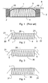
- Figure 1 shows the problem with a known thick and compressible insulation element 1 having been installed between beams or rafters 2, where the insulation have been compressed such that air gaps 10 are formed.
- the wall or ceiling part 8 is the surface against which the insulation element 1 is pushed when introduced between the beams or rafters 2, with the first major surface 3 first.
- Figure 2 shows an embodiment of the invention where a facing 20 is secured to one major surface 3, i.e. the first major surface, of the insulation element 1 and is extending over two opposite side surfaces 5.
- the air gap between the facing 20 and the major surface 3 is obviously out of scale on the illustration. This air gap will in practice be almost non existent and more or less filled with glue or adhesive.
- the parts of the facing 20 extending over the side surfaces 5 are illustrated as not being connected to these, as they are not parallel with the side surfaces 5. These parts, i.e. the flanges 21 of the facing 20, are often of a rectangular shape, so that the extension flange 21 will extend over the same distance in the thickness direction, over the whole side surface. However, the invention will also function if the distance in the thickness direction varies, i.e. if the shape of the extension flange 21 is not rectangular.
- the insulation element 1 may be in the form of a roll or in the form of a slab. If the insulation element 1 is a roll its density will be in the range 10 - 30 kg/m 3 , preferably 18 - 28 kg/m 3 , and even more preferably approximately 23 kg/m 3 . If the insulation element is a slab the density will be in the range 20 - 60 kg/m 3 , preferably 34 - 55 kg/m 3 , and even more preferably the density will have a value around 34 kg/m 3 , 43 kg/m 3 or 55 kg/m 3 .
- the insulation element When the insulation element has the form of rolls, they may, in preferred embodiments of the invention, be produced in various widths, such as 35 cm, 45 cm, 60 cm or 100 cm. The length of the rolls is less relevant.
- the insulation element When the insulation element is a slab it may be produced in various widths, such as 50 - 70 cm and various lengths, such as 90 - 130 cm, preferably the slabs are produced in standard dimensions, such as 60x100 cm and 60x120 cm.
- the thicknesses for both rolls and slab will be at least 10 cm, preferably more than 15 cm, more preferably more than 20 cm, and even more preferably at least 30 cm. The thickness may even be up to 40 cm or 50 cm.
- the width When slabs are produced for wooden frames the width may be in the range 38 cm and 58 cm.
- the slab may be provided with one or more flexible sides, i.e. a side where the fibre structure has been crushed such that compression of the slab, in order to make it fit between rafters, is possible.
- Such one or more flexible sides will obviously lead to a higher compression force of the side surface 5 of the insulation element 1 against the surface of the beam or rafter 2, also when introducing the insulation element 1 between two rafters. Thereby the friction will also be increased.
- the facing 20 often covers a major part of the first major surface 3 of the insulation element 1.
- the facing 20, 21 could be a facing of paper, fleece (e.g. glass fibre fleece), aluminium, aluminium paper, plastic film, etc.
- This facing may be glued with PE on the backside and heat sealed or glued with a binder solution as traditionally used for gluing glass fleece to a slab.
- Other options could be water glass or other liquid glues.
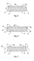
- Figure 3 shows an embodiment of the invention also provided with a second facing 30 attached to the second major surface 4 of the insulation element.
- the second facing 30 may function as a vapour barrier when the insulation element has been installed, and will then be of a material with a low vapour diffusion coefficient.
- the second facing 30 is extending over the area of the second major surface 4. These extending parts, also a kind of flanges 31, are typically applied for fastening the insulation element 1 to the rafters between which it is arranged.
- This second facing 30 with its extending flanges 31 is known from a so-called wing mat, where the wings are the part or flanges 31 of the second facing 30 extending over the area of the second major surface 4.
- the second facing 30, 31 of the installed insulation elements will be taped together during or after installation in order to obtain an airtight vapour barrier.
- the combination of the first 20, 21 and the second 30, 31 facings gives some further advantageous as described above.
- This embodiment of figure 4 is usually applied for rolls, where the second facing 30 is often of aluminium and the extensions 31 will typically extend 4.5 cm over the second major surface 4.
- the second facing 30 is attached to the major surface 4 of the insulation element by the use of glue or adhesive.
- glue or adhesive.
- One possibility is to apply a PE glue, with approximately 20 grams/m 2 , which is then heat sealed to the surface of the mineral fibre insulation by a heat drum.
- the insulation element 1 When the insulation element 1 is in the form of a slab it will usually be faced with glass fleece or aluminium paper.
- Figure 5 shows an embodiment where the extending flanges 21 of the facing 20 are bended around and placed along the rest of the facing 20.
- the facing 20 could be delivered to the manufacturing site of the insulation element 1 folded in this way, and attached to the insulation element with this folding.
- One advantage of this folding is that the extending flanges 21 are held in a position where they are protected during transport and unpacking.
- Figure 6 shows an embodiment where the extension flanges 21 of the facing 20 are secured to a minor part of the side surface 5 in one or more zones 15 along the edge between the first major surface 3 and the side surface 5.
- a minor part of the side surface is meant e.g. a narrow stripe of up to a few centimetres, e.g. 3 cm, along the corner, where the extending flanges 21 are e.g. glued to the side surface 5 of the insulation element 1 in this zone 15.
- the gluing could also be placed in limited areas of this zone 15 with intermediate non glued areas.
- Figure 7 shows an embodiment where the facing 20 only covers a part of the first major surface 3 of the insulation panel 1. This embodiment will save on the amount of facing material needed, and could be advantageous in constructions where a facing on the first major surface 3 of the insulation element is not needed.
- Figure 8 shows how an insulation element 1 according to one embodiment of the invention may be installed between rafters 2.
- the extending flanges 21 of the facing 20 must be arranged such that they will be pressed against the side surfaces 5 of the insulation element 1 when introduced between the rafters.
- the facing 20 must be introduced first.
Landscapes
- Engineering & Computer Science (AREA)
- Architecture (AREA)
- Civil Engineering (AREA)
- Structural Engineering (AREA)
- Physics & Mathematics (AREA)
- Electromagnetism (AREA)
- Acoustics & Sound (AREA)
- Building Environments (AREA)
- Insulation, Fastening Of Motor, Generator Windings (AREA)
- Braking Arrangements (AREA)
- Motor Or Generator Current Collectors (AREA)
- Insulating Bodies (AREA)
- Semiconductor Memories (AREA)
Abstract
A compressible mineral fibre insulation element (1) having a first major surface (3) opposed to a second major surface (4), and having side surfaces (5) connecting the two major surfaces (3, 4) and defining a thickness of the insulation element (1). The thickness is at least 10 cm. The insulation element comprises a facing (20) provided with at least one extension flange (21) of which the outer end (22) is not secured to the insulation element. The facing (20) is attached to at least a part of the first major surface (3), and the extension flange (21) is prepared for extending over and covering a substantial part of the side surface (5) of the insulation element (1). A method of installing a compressible insulation element is also disclosed.
Description
- This invention concerns a compressible mineral fibre insulation element having a first major surface opposed to a second major surface, and having side surfaces connecting the two major surfaces and defining a thickness of the insulation element, said thickness being at least 10 cm, and said insulation element comprises a facing provided with at least one extension flange of which the outer end is not secured to the insulation element, said facing being attached to at least a part of the first major surface. The invention further concerns a method of installing such insulation element.
- The focus on saving on energy use for heating and cooling of buildings has lead to the use of increasing thickness of the insulation layer. When insulating roofs, insulation is often arranged between rafters where it is important with a close fitting to the rafters in order to obtain the best insulation performance.
- The present invention is based on the acknowledgement of a problem when installing such thick insulation between rafters. The problem arises when this thick insulation is also compressible e.g. for reasons of providing the cheapest possible transport from factory to building site. When unpacked at the building site the insulation will expand to the thickness it must have when installed.
- It has been found that, when installing this insulation between beams or rafters air gaps are formed which are not directly visible for the installer. These air gaps are extending along the direction of the rafters.
- These air gaps are formed on the side opposite the side from which the insulation is installed, and is therefore not easily detected, or not realised during installation, to some extend because the installation of the insulation is performed as a task based contract resulting in a high speed of the work. However, such air gaps will considerably reduce the performance of the insulation and will result in higher costs for heating or cooling the building.
- It has now been found that the cause of these air gaps is, that the thick insulation will still be easily compressible when being installed and therefore the friction between the insulation material and the surface of the rafters will make it difficult to push the insulation material all the way into the correct position along the surface of the beams or rafters without the insulation being deformed. This leads to the formation of air gaps extending along the direction of the rafters.
- The objective of the invention has therefore been to find a solution to this new acknowledged problem of avoiding these air gaps without reducing the thickness or the compressibility of the insulation and without increasing installation time.
- The problem has been solved by the inventive compressible mineral fibre insulation element, where an extension flange of the facing is prepared for extending over and covering a substantial part of the side surface of the insulation element.
- The new compressible mineral fibre insulation has the advantage that the part of the facing extending over the side surfaces, in the form of flaps or flanges, in the following called flanges, will provide a coefficient of friction in relation to a wood surface which is smaller than the coefficient of friction of a side surface of the mineral fibre insulation in relation to the same wood surface. By extending the facing over a substantial part, preferably more than half, of the thickness of the insulation element, it has been found that also easily compressible and relatively thick insulation elements, at least 10 cm, can be introduced in between beams or rafters without creating the above mentioned air gaps. This is due to the lower friction against the beam or rafter, which is often made from wood with a rough surface.
- In general, friction is the force that opposes the relative motion or tendency of such motion of two surfaces in contact. The coefficient of friction (also known as the frictional coefficient) is a dimensionless scalar value which describes the ratio of the force of friction between two bodies and the force pressing them together. The coefficient of friction depends on the two materials involved.
- The insulation element of the invention has the advantage that the facing covering a substantial part of, and preferably more than half, the thickness of the insulation element on the at least one side surface has a coefficient of friction in relation to a wood surface which is lower than the coefficient of friction between the side surface of a mineral fibre surface and a wood surface. The wood surfaces in question are often rough, and typically unfinished. The friction is unavoidable since the distance between two neighbouring rafters must be completely filled with insulation material in order to obtain sufficient insulating properties. Therefore, the insulation element must fill up the whole distance between rafters.
- By applying this facing it is possible to obtain a frictional force when installing the insulation element between (especially wooden) beams or rafters, which is smaller than the force needed for substantial deformation of the insulation material in the direction of its thickness. Such deformation would typically result in the formation of air gaps.
- The insulation elements of the invention may have the form of rolls and slabs. By the term compressible is meant that the insulation element may, by applying a compression force, be compressed to a thickness of 70 % of the original thickness, preferably 60 %, more preferably 50 %, and even more preferably 40 % or less of the original thickness, and when the compression force is removed the insulation element will re-expand to the original thickness or substantially the original thickness.
- In a preferred embodiment the extension flanges of the facing is extending over two opposed side surfaces, which makes installation easier. Preferably, at least one extension flange is prepared for extending over more than 50 %, i.e. half, of the side surface of the insulation element, preferably over at least 75 %, i.e. three quarters, of the side surface of the insulation element, and even more preferably, at least one extension flange is prepared for extending over the whole or substantially the whole side surface of the insulation element. The larger a part of the surface covered by the facing the lower friction is obtained.
- In a further embodiment the insulation element, either roll or slab, is being covered on both of the two major surfaces by a facing. The facing on the first major surface will have extending flanges over at least one side surface, whereas the facing on the second major surface will be useful for the formation of a vapour barrier. The facing on the second major surface may also be provided with extensions which can be used for fastening the insulation element to beams or rafters. One advantage of having facings on both major surfaces is the reduction of the direct contact with the fibrous surfaces when persons are installing the insulation. Furthermore the release of fibres to the air, when handling the insulation elements, is reduced when a larger part of the surfaces is having a facing. These two advantages can be achieved without sacrificing the advantage of the insulation element according to the invention, i.e. that the insulation element is easily compressible for transport purposes, since no facing is attached to the major part of each of the side surfaces.
- Both facings are attached, e.g. by gluing, to the major surfaces of the mineral fibre insulation element, while no facings is attached to the majority of the area of the sides of the insulation element. The facing on the first major surface will always extend over the side surfaces of the insulation element. The facing on the second major surface may extend over the side surfaces, but not necessarily. If the facing on the second major surface extends over the side surfaces the length of this extension will usually be in the range 4 - 5 cm, and this extension is for mounting reasons e.g. by nailing.
- The facing on the first major surface can be extending as wide as the thickness of the insulation element itself, and will at least extend over half the thickness. These extension flanges are for reducing friction between the insulation material (usually mineral fibres) and the rafters or wooden frame.
- Furthermore, both facings may be used for any type of graphics, e.g. for branding, or for markings helping for mounting, fixing or cutting.
- The invention also concerns a method of installing a compressible insulation element between a pair of beams or rafters, comprising the steps of 1) providing a compressible mineral fibre insulation element having a first major surface opposed to a second major surface, and having side surfaces connecting the two major surfaces and defining a thickness of the insulation element, said insulation element comprises a facing provided with at least one extension flange of which the outer end is not secured to the insulation element, said facing being attached to at least a part of the first major surface and said extension flange of the facing is prepared for extending over and covering at least a part of the area of at least one side surface; 2) covering a part of at least one side surface by said facing; 3) introducing the insulation element in between a pair of beams or rafters with said first major surface with the facing entering first.
- Preferably this method also comprises the step of unpacking the insulation element and letting it expand to the non compressed thickness.
- Preferably the insulation element is attached to the beams or rafters by the use of a further second facing attached to the second major surface of the insulation element; said second facing having flanges extending beyond the area of the second major surface, and said flanges being used for attachment of the insulation element.
- Different embodiments of the invention will now be described in further details with reference to the figures, where:
-
Figure 1 illustrates the acknowledged problem with some prior art solutions. -
Figure 2 illustrates a cross sectional view of insulation element with a facing extending over two minor surfaces of the insulation product. -
Figure 3 illustrates an insulation element with a facing extending over two minor surfaces and one further facing covering a major surface. -
Figure 4 illustrates an insulation element with a facing extending over two minor surfaces and one further facing covering a major surface having sides extending the insulation product for mounting/fixing the insulation product. -
Figure 5 illustrates the embodiment offigure 2 with the extending flanges of the facing bended around and placed on the rest of the facing. -
Figure 6 illustrates an embodiment where the extension flanges of the facing are secured to a minor part of the side surface. -
Figure 7 illustrates an embodiment where the facing is only covering and attached to a part of the first major surface of the insulation element. -
Figure 8 illustrates part of the method of installing an insulation element according to one embodiment of the invention between rafters. -
Figure 1 shows the problem with a known thick andcompressible insulation element 1 having been installed between beams orrafters 2, where the insulation have been compressed such thatair gaps 10 are formed. The wall orceiling part 8 is the surface against which theinsulation element 1 is pushed when introduced between the beams orrafters 2, with the firstmajor surface 3 first. -
Figure 2 shows an embodiment of the invention where a facing 20 is secured to onemajor surface 3, i.e. the first major surface, of theinsulation element 1 and is extending over twoopposite side surfaces 5. The air gap between the facing 20 and themajor surface 3 is obviously out of scale on the illustration. This air gap will in practice be almost non existent and more or less filled with glue or adhesive. The parts of the facing 20 extending over theside surfaces 5 are illustrated as not being connected to these, as they are not parallel with theside surfaces 5. These parts, i.e. theflanges 21 of the facing 20, are often of a rectangular shape, so that theextension flange 21 will extend over the same distance in the thickness direction, over the whole side surface. However, the invention will also function if the distance in the thickness direction varies, i.e. if the shape of theextension flange 21 is not rectangular. - For the embodiment illustrated in
figure 2 and also for the embodiments described below it applies that theinsulation element 1 may be in the form of a roll or in the form of a slab. If theinsulation element 1 is a roll its density will be in the range 10 - 30 kg/m3, preferably 18 - 28 kg/m3, and even more preferably approximately 23 kg/m3. If the insulation element is a slab the density will be in the range 20 - 60 kg/m3, preferably 34 - 55 kg/m3, and even more preferably the density will have a value around 34 kg/m3, 43 kg/m3 or 55 kg/m3. - When the insulation element has the form of rolls, they may, in preferred embodiments of the invention, be produced in various widths, such as 35 cm, 45 cm, 60 cm or 100 cm. The length of the rolls is less relevant. When the insulation element is a slab it may be produced in various widths, such as 50 - 70 cm and various lengths, such as 90 - 130 cm, preferably the slabs are produced in standard dimensions, such as 60x100 cm and 60x120 cm. The thicknesses for both rolls and slab will be at least 10 cm, preferably more than 15 cm, more preferably more than 20 cm, and even more preferably at least 30 cm. The thickness may even be up to 40 cm or 50 cm. When slabs are produced for wooden frames the width may be in the range 38 cm and 58 cm. In this case the slab may be provided with one or more flexible sides, i.e. a side where the fibre structure has been crushed such that compression of the slab, in order to make it fit between rafters, is possible. Such one or more flexible sides will obviously lead to a higher compression force of the
side surface 5 of theinsulation element 1 against the surface of the beam orrafter 2, also when introducing theinsulation element 1 between two rafters. Thereby the friction will also be increased. - The facing 20 often covers a major part of the first
major surface 3 of theinsulation element 1. The facing 20, 21 could be a facing of paper, fleece (e.g. glass fibre fleece), aluminium, aluminium paper, plastic film, etc. This facing may be glued with PE on the backside and heat sealed or glued with a binder solution as traditionally used for gluing glass fleece to a slab. Other options could be water glass or other liquid glues. -
Figure 3 shows an embodiment of the invention also provided with asecond facing 30 attached to the secondmajor surface 4 of the insulation element. - The
second facing 30 may function as a vapour barrier when the insulation element has been installed, and will then be of a material with a low vapour diffusion coefficient. - In
figure 4 thesecond facing 30 is extending over the area of the secondmajor surface 4. These extending parts, also a kind offlanges 31, are typically applied for fastening theinsulation element 1 to the rafters between which it is arranged. This second facing 30 with its extendingflanges 31 is known from a so-called wing mat, where the wings are the part orflanges 31 of thesecond facing 30 extending over the area of the secondmajor surface 4. For both the embodiment infigure 3 and infigure 4 thesecond facing - This embodiment of
figure 4 is usually applied for rolls, where thesecond facing 30 is often of aluminium and theextensions 31 will typically extend 4.5 cm over the secondmajor surface 4. Thesecond facing 30 is attached to themajor surface 4 of the insulation element by the use of glue or adhesive. One possibility is to apply a PE glue, with approximately 20 grams/m2, which is then heat sealed to the surface of the mineral fibre insulation by a heat drum. - When the
insulation element 1 is in the form of a slab it will usually be faced with glass fleece or aluminium paper. -
Figure 5 shows an embodiment where the extendingflanges 21 of the facing 20 are bended around and placed along the rest of the facing 20. The facing 20 could be delivered to the manufacturing site of theinsulation element 1 folded in this way, and attached to the insulation element with this folding. - One advantage of this folding is that the extending
flanges 21 are held in a position where they are protected during transport and unpacking. -
Figure 6 shows an embodiment where theextension flanges 21 of the facing 20 are secured to a minor part of theside surface 5 in one ormore zones 15 along the edge between the firstmajor surface 3 and theside surface 5. By a minor part of the side surface is meant e.g. a narrow stripe of up to a few centimetres, e.g. 3 cm, along the corner, where the extendingflanges 21 are e.g. glued to theside surface 5 of theinsulation element 1 in thiszone 15. The gluing could also be placed in limited areas of thiszone 15 with intermediate non glued areas. -
Figure 7 shows an embodiment where the facing 20 only covers a part of the firstmajor surface 3 of theinsulation panel 1. This embodiment will save on the amount of facing material needed, and could be advantageous in constructions where a facing on the firstmajor surface 3 of the insulation element is not needed. -
Figure 8 shows how aninsulation element 1 according to one embodiment of the invention may be installed betweenrafters 2. The extendingflanges 21 of the facing 20 must be arranged such that they will be pressed against the side surfaces 5 of theinsulation element 1 when introduced between the rafters. The facing 20 must be introduced first.
Claims (14)
- A compressible mineral fibre insulation element (1) having a first major surface (3) opposed to a second major surface (4), and having side surfaces (5) connecting the two major surfaces (3, 4) and defining a thickness of the insulation element (1), said thickness being at least 10 cm, and said insulation element comprises a facing (20) provided with at least one extension flange (21) of which the outer end (22) is not secured to the insulation element, said facing (20) being attached to at least a part of the first major surface (3), characterised in that said extension flange (21) is prepared for extending over and covering a substantial part of the side surface (5) of the insulation element (1).
- Insulation element according to claim 1, including extension flanges (21) extending over two opposed side surfaces (5).
- Insulation element according to claim 1 or 2, wherein at least one extension flange (21) is prepared for extending over more than 50 %, i.e. half, of the side surface of the insulation element (1), preferably over at least 75 %, i.e. three quarters, and more preferably the at least one extension flange (21) is prepared for extending over the whole or substantially the whole side surface of the insulation element (1).
- Insulation element according to any one of the previous claims, wherein the thickness of the insulation element is more than 15 cm, preferably more than 20 cm, and even more preferably at least 30 cm.
- Insulation element according to any one of the previous claims, wherein the extension flange (21) is not secured to the side surface (5).
- Insulation element according to any one of the claims 1 - 4, wherein the extension flange (21) is secured to a minor part of the side surface (5) in one or more zones (15) along the edge between the first major surface (3) and the side surface (5).
- Insulation element according to any one of the previous claims, wherein the facing (20) covers a major part of the first major surface (3) of the insulation element (1).
- Insulation element according to any one of the previous claims, wherein the facing (20, 21) is selected from the group: paper, fleece, aluminium paper, aluminium foil, plastic film.
- Insulation element according to any one of the previous claims, wherein the second major surface (4) of the insulation element is provided with a further second facing (30).
- Insulation according to claim 9, wherein said second facing (30) on the second major surface (4) of the insulation element (1) is provided with flanges (31) extending beyond said second major surface (4), and prepared for being used for attachment of the insulation.
- Method of installing a compressible insulation element (1) between a pair of beams or rafters (2), comprising the steps of- providing a compressible mineral fibre insulation element (1) having a first major surface (3) opposed to a second major surface (4), and having side surfaces (5) connecting the two major surfaces (3, 4) and defining a thickness of the insulation element (1), said insulation element comprises a facing (20) provided with at least one extension flange (21) of which the outer end (22) is not secured to the insulation element, said facing (20) being attached to at least a part of the first major surface (3) and said extension flange (21) of the facing (20) is prepared for extending over and covering at least a part of the area of at least one side surface (5);- covering a part of at least one side surface (5) by said facing (21);- introducing the insulation element in between a pair of beams or rafters (2) with said first major surface (3) with the facing (20) entering first.
- Method of installing an insulation element (1) according to claim 11, wherein said insulation element (1) is in accordance with the insulation element of any one of claims 1 - 10.
- Method of installing an insulation element (1) according to claim 11 or 12, wherein said method also comprises the step of unpacking the insulation element (1) and letting it expand to the non compressed thickness.
- Method of installing an insulation element (1) according to claim 11, 12 or 13, wherein the insulation element (1) is attached to the beams or rafters by the use of a further second facing (30) attached to the second major surface (4) of the insulation element (1); said second facing (30) having flanges (31) extending beyond the area of the second major surface (4), and said flanges (31) being used for attachment of the insulation element (1).
Priority Applications (11)
| Application Number | Priority Date | Filing Date | Title |
|---|---|---|---|
| EP07388007A EP1956155A1 (en) | 2007-02-12 | 2007-02-12 | A compressible insulation element with reduced friction |
| CA2677744A CA2677744C (en) | 2007-02-12 | 2008-02-08 | A compressible insulation element with reduced friction |
| AT08716781T ATE495320T1 (en) | 2007-02-12 | 2008-02-08 | COMPRESSABLE INSULATION ELEMENT WITH REDUCED FRICTION |
| EP08716781A EP2118390B1 (en) | 2007-02-12 | 2008-02-08 | A compressible insulation element with reduced friction |
| EA200970759A EA015083B1 (en) | 2007-02-12 | 2008-02-08 | Insulation element |
| DK08716781.3T DK2118390T3 (en) | 2007-02-12 | 2008-02-08 | Compressible reduced friction insulating element |
| SI200830206T SI2118390T1 (en) | 2007-02-12 | 2008-02-08 | A compressible insulation element with reduced friction |
| PL08716781T PL2118390T3 (en) | 2007-02-12 | 2008-02-08 | A compressible insulation element with reduced friction |
| US12/526,745 US8161703B2 (en) | 2007-02-12 | 2008-02-08 | Compressible insulation element with reduced friction |
| DE602008004455T DE602008004455D1 (en) | 2007-02-12 | 2008-02-08 | COMPRESSIBLE INSULATION ELEMENT WITH REDUCED FRICTION |
| PCT/EP2008/051565 WO2008098884A1 (en) | 2007-02-12 | 2008-02-08 | A compressible insulation element with reduced friction |
Applications Claiming Priority (1)
| Application Number | Priority Date | Filing Date | Title |
|---|---|---|---|
| EP07388007A EP1956155A1 (en) | 2007-02-12 | 2007-02-12 | A compressible insulation element with reduced friction |
Publications (1)
| Publication Number | Publication Date |
|---|---|
| EP1956155A1 true EP1956155A1 (en) | 2008-08-13 |
Family
ID=38180671
Family Applications (2)
| Application Number | Title | Priority Date | Filing Date |
|---|---|---|---|
| EP07388007A Withdrawn EP1956155A1 (en) | 2007-02-12 | 2007-02-12 | A compressible insulation element with reduced friction |
| EP08716781A Not-in-force EP2118390B1 (en) | 2007-02-12 | 2008-02-08 | A compressible insulation element with reduced friction |
Family Applications After (1)
| Application Number | Title | Priority Date | Filing Date |
|---|---|---|---|
| EP08716781A Not-in-force EP2118390B1 (en) | 2007-02-12 | 2008-02-08 | A compressible insulation element with reduced friction |
Country Status (10)
| Country | Link |
|---|---|
| US (1) | US8161703B2 (en) |
| EP (2) | EP1956155A1 (en) |
| AT (1) | ATE495320T1 (en) |
| CA (1) | CA2677744C (en) |
| DE (1) | DE602008004455D1 (en) |
| DK (1) | DK2118390T3 (en) |
| EA (1) | EA015083B1 (en) |
| PL (1) | PL2118390T3 (en) |
| SI (1) | SI2118390T1 (en) |
| WO (1) | WO2008098884A1 (en) |
Cited By (2)
| Publication number | Priority date | Publication date | Assignee | Title |
|---|---|---|---|---|
| WO2008149090A1 (en) * | 2007-06-04 | 2008-12-11 | Hunt Technology Limited | Thermal insulation structure |
| BE1024671B1 (en) * | 2017-04-05 | 2018-05-17 | Recticel | Insulation panel and method for fixing thereof |
Families Citing this family (6)
| Publication number | Priority date | Publication date | Assignee | Title |
|---|---|---|---|---|
| US20100287860A1 (en) * | 2006-02-28 | 2010-11-18 | Fernandez-Cano Pedro Luis | Insulated Facade System |
| US20130094791A1 (en) * | 2011-10-17 | 2013-04-18 | Mark A. Aspenson | Building insulation system |
| US9834923B1 (en) * | 2015-08-10 | 2017-12-05 | Robert Lepage | Building construction method |
| US10267030B1 (en) * | 2015-08-10 | 2019-04-23 | Robert Lepage | Building construction method |
| US9920517B2 (en) | 2016-08-17 | 2018-03-20 | Pratt Corrugated Holdings, Inc. | Insulation batt |
| US11813833B2 (en) | 2019-12-09 | 2023-11-14 | Owens Corning Intellectual Capital, Llc | Fiberglass insulation product |
Citations (6)
| Publication number | Priority date | Publication date | Assignee | Title |
|---|---|---|---|---|
| US2913104A (en) * | 1957-10-14 | 1959-11-17 | Celotex Corp | Packaging of insulating blankets |
| DE3136935C1 (en) * | 1981-09-17 | 1983-04-14 | Deutsche Rockwool Mineralwoll-GmbH, 4390 Gladbeck | Web or panel of mineral wool, in particular rockwool |
| US5362539A (en) * | 1992-12-30 | 1994-11-08 | Owens-Corning Fiberglas Technology Inc. | Mineral fiber insulation assembly |
| WO1997008401A1 (en) * | 1995-08-31 | 1997-03-06 | Certainteed Corporation | Encapsulated insulation assembly |
| US6579586B1 (en) * | 2000-09-28 | 2003-06-17 | Johns Manville International, Inc. | Encapsulated insulation batt assembly |
| US20040088939A1 (en) * | 2002-11-08 | 2004-05-13 | Fay Ralph Michael | Facing and faced building insulation |
Family Cites Families (16)
| Publication number | Priority date | Publication date | Assignee | Title |
|---|---|---|---|---|
| AT320238B (en) * | 1971-01-13 | 1975-01-27 | Certain Teed St Gobain | Insulating element for building purposes |
| US3955031A (en) * | 1973-01-18 | 1976-05-04 | Owens-Corning Fiberglas Corporation | Flame resistant building material |
| KR100189213B1 (en) | 1993-06-03 | 1999-06-01 | 휴스톤 로버트 엘 | Insulation batt with low friction facing |
| US5624726A (en) * | 1995-01-09 | 1997-04-29 | Minnesota Mining And Manufacturing Company | Insulation blanket |
| US6141930A (en) * | 1996-04-16 | 2000-11-07 | Johns Manville International, Inc. | Method of and article for insulating standard and nonstandard cavities and an insulated structure |
| US6534144B1 (en) * | 1996-09-27 | 2003-03-18 | Asahi Fiber Glass Company Limited | Synthetic resin film covered heat insulating/sound absorbing material of inorganic fibers and a method of producing the same |
| US5765318A (en) * | 1997-02-06 | 1998-06-16 | Johns Manville International, Inc. | Segmented, encapsulated insulation assembly |
| US6083603A (en) * | 1998-01-30 | 2000-07-04 | Owens Corning Fiberglas Technology, Inc. | Flanged insulation assembly and method of making |
| WO1999063175A1 (en) * | 1998-06-02 | 1999-12-09 | Owens Corning | Facing system for an insulation product |
| US6128884A (en) * | 1998-06-02 | 2000-10-10 | Owens Corning Fiberglas Technology, Inc. | Universal insulation product and method for installing |
| BE1014482A3 (en) | 2001-11-19 | 2003-11-04 | Alcopor Knauf Technology Ag | Encapsulated insulating material, comprises fibre mat with covered main and lateral surfaces and vapor-proof under layer |
| US6878427B2 (en) * | 2002-12-20 | 2005-04-12 | Kimberly Clark Worldwide, Inc. | Encased insulation article |
| US7282252B2 (en) * | 2003-03-20 | 2007-10-16 | Johns Manville | Faced insulation assembly and method |
| US7780886B2 (en) * | 2003-10-21 | 2010-08-24 | Certainteed Corporation | Insulation product having directional facing layer thereon and method of making the same |
| US7252868B2 (en) | 2004-01-08 | 2007-08-07 | Certainteed Corporation | Reinforced fibrous insulation product and method of reinforcing same |
| US20060201089A1 (en) * | 2005-03-09 | 2006-09-14 | Duncan Richard S | Spray foam and mineral wool hybrid insulation system |
-
2007
- 2007-02-12 EP EP07388007A patent/EP1956155A1/en not_active Withdrawn
-
2008
- 2008-02-08 EP EP08716781A patent/EP2118390B1/en not_active Not-in-force
- 2008-02-08 AT AT08716781T patent/ATE495320T1/en active
- 2008-02-08 US US12/526,745 patent/US8161703B2/en not_active Expired - Fee Related
- 2008-02-08 EA EA200970759A patent/EA015083B1/en not_active IP Right Cessation
- 2008-02-08 PL PL08716781T patent/PL2118390T3/en unknown
- 2008-02-08 CA CA2677744A patent/CA2677744C/en not_active Expired - Fee Related
- 2008-02-08 WO PCT/EP2008/051565 patent/WO2008098884A1/en active Application Filing
- 2008-02-08 DE DE602008004455T patent/DE602008004455D1/en active Active
- 2008-02-08 SI SI200830206T patent/SI2118390T1/en unknown
- 2008-02-08 DK DK08716781.3T patent/DK2118390T3/en active
Patent Citations (6)
| Publication number | Priority date | Publication date | Assignee | Title |
|---|---|---|---|---|
| US2913104A (en) * | 1957-10-14 | 1959-11-17 | Celotex Corp | Packaging of insulating blankets |
| DE3136935C1 (en) * | 1981-09-17 | 1983-04-14 | Deutsche Rockwool Mineralwoll-GmbH, 4390 Gladbeck | Web or panel of mineral wool, in particular rockwool |
| US5362539A (en) * | 1992-12-30 | 1994-11-08 | Owens-Corning Fiberglas Technology Inc. | Mineral fiber insulation assembly |
| WO1997008401A1 (en) * | 1995-08-31 | 1997-03-06 | Certainteed Corporation | Encapsulated insulation assembly |
| US6579586B1 (en) * | 2000-09-28 | 2003-06-17 | Johns Manville International, Inc. | Encapsulated insulation batt assembly |
| US20040088939A1 (en) * | 2002-11-08 | 2004-05-13 | Fay Ralph Michael | Facing and faced building insulation |
Cited By (3)
| Publication number | Priority date | Publication date | Assignee | Title |
|---|---|---|---|---|
| WO2008149090A1 (en) * | 2007-06-04 | 2008-12-11 | Hunt Technology Limited | Thermal insulation structure |
| BE1024671B1 (en) * | 2017-04-05 | 2018-05-17 | Recticel | Insulation panel and method for fixing thereof |
| EP3385464A1 (en) * | 2017-04-05 | 2018-10-10 | Recticel | Insulating panel and method for fixing thereof |
Also Published As
| Publication number | Publication date |
|---|---|
| SI2118390T1 (en) | 2011-05-31 |
| EA015083B1 (en) | 2011-04-29 |
| EP2118390A1 (en) | 2009-11-18 |
| ATE495320T1 (en) | 2011-01-15 |
| CA2677744A1 (en) | 2008-08-21 |
| US20100146896A1 (en) | 2010-06-17 |
| CA2677744C (en) | 2013-01-22 |
| WO2008098884A1 (en) | 2008-08-21 |
| DK2118390T3 (en) | 2011-04-18 |
| US8161703B2 (en) | 2012-04-24 |
| EP2118390B1 (en) | 2011-01-12 |
| EA200970759A1 (en) | 2010-02-26 |
| DE602008004455D1 (en) | 2011-02-24 |
| PL2118390T3 (en) | 2011-06-30 |
Similar Documents
| Publication | Publication Date | Title |
|---|---|---|
| EP2118390B1 (en) | A compressible insulation element with reduced friction | |
| US5765318A (en) | Segmented, encapsulated insulation assembly | |
| US8132381B2 (en) | Flangeless insulation product for compression fitting into insulation cavities | |
| WO1998035109A9 (en) | Segmented, encapsulated insulation assembly | |
| EP1987208B1 (en) | Thermal insulation plate comprising an insulating core and an elevated surface portion, thermally insulated structure of such plates and method for constructing such structure | |
| EP2809852B1 (en) | Building construction panels | |
| US20230383540A1 (en) | Modular Partition System | |
| EP2657426B1 (en) | Sandwich panel and panel system | |
| EP3601689B1 (en) | Panel for a partition | |
| US11028290B2 (en) | Heat-applied gap finishing tape | |
| JP3819039B2 (en) | Insulating elements for clamp assembly between beams of roof rafters or other timber structures | |
| HU224894B1 (en) | Substrate for sound isolation of floating floors | |
| US20090260310A1 (en) | Method and system for providing an insulative wall structure | |
| EP3385464B1 (en) | Insulating panel and method for fixing thereof | |
| EP2547834B1 (en) | Air gap barrier | |
| CN110374239A (en) | A kind of open tubular column grating type floor plates | |
| CA2872475A1 (en) | Blown insulation apparatus and method | |
| GB2444181A (en) | Air tight system for building with vapour impermeable sealing strips | |
| JP2009052315A (en) | Structure for sticking wall material and wall covering material together |
Legal Events
| Date | Code | Title | Description |
|---|---|---|---|
| PUAI | Public reference made under article 153(3) epc to a published international application that has entered the european phase |
Free format text: ORIGINAL CODE: 0009012 |
|
| AK | Designated contracting states |
Kind code of ref document: A1 Designated state(s): AT BE BG CH CY CZ DE DK EE ES FI FR GB GR HU IE IS IT LI LT LU LV MC NL PL PT RO SE SI SK TR |
|
| AX | Request for extension of the european patent |
Extension state: AL BA HR MK RS |
|
| AKX | Designation fees paid | ||
| REG | Reference to a national code |
Ref country code: DE Ref legal event code: 8566 |
|
| STAA | Information on the status of an ep patent application or granted ep patent |
Free format text: STATUS: THE APPLICATION IS DEEMED TO BE WITHDRAWN |
|
| 18D | Application deemed to be withdrawn |
Effective date: 20090214 |