EP1952133B1 - High impedance system for generating electric fields and method of use - Google Patents
High impedance system for generating electric fields and method of use Download PDFInfo
- Publication number
- EP1952133B1 EP1952133B1 EP06827315.0A EP06827315A EP1952133B1 EP 1952133 B1 EP1952133 B1 EP 1952133B1 EP 06827315 A EP06827315 A EP 06827315A EP 1952133 B1 EP1952133 B1 EP 1952133B1
- Authority
- EP
- European Patent Office
- Prior art keywords
- fluid
- space
- electrodes
- pathway
- electric field
- Prior art date
- Legal status (The legal status is an assumption and is not a legal conclusion. Google has not performed a legal analysis and makes no representation as to the accuracy of the status listed.)
- Not-in-force
Links
Images


Classifications
-
- G—PHYSICS
- G01—MEASURING; TESTING
- G01N—INVESTIGATING OR ANALYSING MATERIALS BY DETERMINING THEIR CHEMICAL OR PHYSICAL PROPERTIES
- G01N27/00—Investigating or analysing materials by the use of electric, electrochemical, or magnetic means
-
- A—HUMAN NECESSITIES
- A61—MEDICAL OR VETERINARY SCIENCE; HYGIENE
- A61N—ELECTROTHERAPY; MAGNETOTHERAPY; RADIATION THERAPY; ULTRASOUND THERAPY
- A61N1/00—Electrotherapy; Circuits therefor
- A61N1/02—Details
- A61N1/04—Electrodes
- A61N1/0404—Electrodes for external use
- A61N1/0408—Use-related aspects
- A61N1/0412—Specially adapted for transcutaneous electroporation, e.g. including drug reservoirs
- A61N1/0416—Anode and cathode
- A61N1/042—Material of the electrode
-
- A—HUMAN NECESSITIES
- A61—MEDICAL OR VETERINARY SCIENCE; HYGIENE
- A61N—ELECTROTHERAPY; MAGNETOTHERAPY; RADIATION THERAPY; ULTRASOUND THERAPY
- A61N1/00—Electrotherapy; Circuits therefor
- A61N1/02—Details
- A61N1/04—Electrodes
- A61N1/0404—Electrodes for external use
- A61N1/0408—Use-related aspects
- A61N1/0412—Specially adapted for transcutaneous electroporation, e.g. including drug reservoirs
- A61N1/0416—Anode and cathode
- A61N1/0424—Shape of the electrode
-
- A—HUMAN NECESSITIES
- A61—MEDICAL OR VETERINARY SCIENCE; HYGIENE
- A61N—ELECTROTHERAPY; MAGNETOTHERAPY; RADIATION THERAPY; ULTRASOUND THERAPY
- A61N1/00—Electrotherapy; Circuits therefor
- A61N1/18—Applying electric currents by contact electrodes
- A61N1/32—Applying electric currents by contact electrodes alternating or intermittent currents
- A61N1/327—Applying electric currents by contact electrodes alternating or intermittent currents for enhancing the absorption properties of tissue, e.g. by electroporation
-
- G—PHYSICS
- G01—MEASURING; TESTING
- G01N—INVESTIGATING OR ANALYSING MATERIALS BY DETERMINING THEIR CHEMICAL OR PHYSICAL PROPERTIES
- G01N27/00—Investigating or analysing materials by the use of electric, electrochemical, or magnetic means
- G01N27/02—Investigating or analysing materials by the use of electric, electrochemical, or magnetic means by investigating impedance
-
- H—ELECTRICITY
- H05—ELECTRIC TECHNIQUES NOT OTHERWISE PROVIDED FOR
- H05H—PLASMA TECHNIQUE; PRODUCTION OF ACCELERATED ELECTRICALLY-CHARGED PARTICLES OR OF NEUTRONS; PRODUCTION OR ACCELERATION OF NEUTRAL MOLECULAR OR ATOMIC BEAMS
- H05H1/00—Generating plasma; Handling plasma
- H05H1/24—Generating plasma
- H05H1/2406—Generating plasma using dielectric barrier discharges, i.e. with a dielectric interposed between the electrodes
- H05H1/2443—Generating plasma using dielectric barrier discharges, i.e. with a dielectric interposed between the electrodes the plasma fluid flowing through a dielectric tube
- H05H1/246—Generating plasma using dielectric barrier discharges, i.e. with a dielectric interposed between the electrodes the plasma fluid flowing through a dielectric tube the plasma being activated using external electrodes
-
- G—PHYSICS
- G01—MEASURING; TESTING
- G01N—INVESTIGATING OR ANALYSING MATERIALS BY DETERMINING THEIR CHEMICAL OR PHYSICAL PROPERTIES
- G01N27/00—Investigating or analysing materials by the use of electric, electrochemical, or magnetic means
- G01N27/26—Investigating or analysing materials by the use of electric, electrochemical, or magnetic means by investigating electrochemical variables; by using electrolysis or electrophoresis
- G01N27/416—Systems
- G01N27/447—Systems using electrophoresis
- G01N27/44704—Details; Accessories
- G01N27/44713—Particularly adapted electric power supply
Landscapes
- Engineering & Computer Science (AREA)
- Life Sciences & Earth Sciences (AREA)
- Health & Medical Sciences (AREA)
- Physics & Mathematics (AREA)
- General Health & Medical Sciences (AREA)
- Plasma & Fusion (AREA)
- Biophysics (AREA)
- Radiology & Medical Imaging (AREA)
- Animal Behavior & Ethology (AREA)
- Nuclear Medicine, Radiotherapy & Molecular Imaging (AREA)
- Public Health (AREA)
- Veterinary Medicine (AREA)
- Biomedical Technology (AREA)
- Spectroscopy & Molecular Physics (AREA)
- Bioinformatics & Cheminformatics (AREA)
- Chemical & Material Sciences (AREA)
- Pathology (AREA)
- Electrochemistry (AREA)
- Analytical Chemistry (AREA)
- Biochemistry (AREA)
- General Physics & Mathematics (AREA)
- Immunology (AREA)
- Chemical Kinetics & Catalysis (AREA)
- Fluid Mechanics (AREA)
- Physical Or Chemical Processes And Apparatus (AREA)
- Water Treatment By Electricity Or Magnetism (AREA)
- Investigating Or Analyzing Materials By The Use Of Electric Means (AREA)
- Apparatus Associated With Microorganisms And Enzymes (AREA)
- Immobilizing And Processing Of Enzymes And Microorganisms (AREA)
- Apparatus For Disinfection Or Sterilisation (AREA)
Description
- The embodiments of the present invention relate to a system for applying time variant, time invariant, or pulsed voltage potential to a series capacitive network to set up or otherwise generate uniform or non-uniform electric fields, which in turn, are used for numerous applications. More particularly, the embodiments employ dielectric materials with particular electrical properties, arranged or otherwise configured to form series capacitance networks that divide or otherwise distribute the applied potential between opposing electrodes, resulting in a concentration of the E- field in (or otherwise through) a subject material.
- Static, time variant, and pulsed electric fields, with or without a magnetic field component, whether considered weak or intense for a particular application, are used in a variety of industries for a broad range of applications. In some existing applications, and where time variant applied voltages are used with the embodiments of the present invention, charge carriers may be moving relative to the lab frame so a magnetic B-field component accompanies the electric E-field, however, with the embodiments of the present invention, only the E-field is pertinent. Examples of E-field applications include, but are not limited to the following:
- electrophoresis: both gel and capillary type employ an electrical current through suspension media, the resistive load, thus setting up an electric field used to separate, differentiate and fractionate DNA, proteins, and other molecules;
- electroporation (aka electropermeabilization): intense electric fields, often pulsed with various waveforms and pulse rates, are used to cause the dielectric breakdown of living cellular membranes, thus affecting reversible and nonreversible poration and/or permeabilization for the purpose of transfection, pasteurization or sterilization; and
- electric field flow fractionation (FFF, aka EFFF, µ-EFF, CyEFF, and others): employ an electric field orthogonal to a fluid flow in order to separate, fractionate, and differentiate large molecules and/or small particles from a subject liquid.
- Generally speaking, a process or effect driven, supported or facilitated by the action of an E-field can be accelerated or otherwise improved by either increasing the field intensity for a given applied voltage, or conversely, by reducing the applied voltage for a given field intensity. This is due to the relationship between the material properties of permittivity, volume resistivity, and maximum allowable field stress, and the effect these parameters have on the diacritical circuit elements of field intensity, dielectric breakdown, field geometry, current flow, and energy consumption. Applications proceeding under the influence or direct action of an E-field are often limited by the undesirable effects of ohmic heating, electrochemistry (faradaic charge transfer), field shielding by electrolytic double layer formation, electrode polarization, and energy consumption.
- Electric current is a limiting factor for the applied filed intensity in electrophoretic, electroporation, and field flow fractionation devices due to ohmic heating of the working media (usually a liquid or gel for such applications), and undesirable electrochemistry at the media/electrode interface(s) (faradaic charge transfer). For example, much effort has been expended over the last two decades to apply the process of clinical electroporation (primarily used for transfection of living biological cells) to commercial isothermal pasteurization (commonly know as Pulsed Electric Field non-thermal pasteurization or PEF). Reversible electroporation is non-lethal and is accomplished by careful control of the applied field intensity and exposure time, where irreversible electroporation is marked by cellular death, metabolic inactivation, or apoptosis. Due to the low impedance nature of PEF systems, where bare conductive electrodes are coupled directly to the fluid under treatment, pulsed voltage waveforms have been employed as a means to reduce average energy, ohmic heating, and undesirable electrochemistry at the fluid/electrode interface. The same is true for electrophoresis and electric field flow fractionation (EFFF) methods and devices. Although an increase in field intensity would improve the efficiency and/or rate of process, increasing the applied voltage as a means to increase field intensity results in excessive electric current and the associated ohmic heating, undesirable electrochemical reactions, and the other undesirable reactions referenced above. In the case of EFFF, recent efforts have been made to reduce the fluid channel height using micromachining and microelectronic techniques thereby effectively reducing the field dimension between the electrodes and thus increasing field intensity while mitigating electric current flow. Since increasing the E-field intensity also requires an increase in the applied voltage, and/or a decrease in the distance between the electrodes, dielectric breakdown of the working media, whether a gas, liquid, or solid, is an additional limiting factor in all applications.
- Although coating or juxtaposing common dielectric materials between traditional electrically conductive electrodes and the media under treatment allows higher voltage to be applied, implying a higher E-field intensity, the effect is offset by a much larger voltage drop across the dielectric material being used, thus lowering the E-field in the media under treatment. This occurs because of the manner in which voltage drops, and therefore the E-field, is divided or otherwise distributed in series capacitance networks.
- It would be advantageous to develop a system for generating an E-field that significantly mitigates or completely resolves the undesirable effects of the previous systems and methods.
- Accordingly, one embodiment of the present invention includes a high impedance system for generating an electric field and comprises: a pair of electrodes comprising a dielectric material wherein each electrode has at least one surface coated with a conductive material; and wherein such dielectric material forms a barrier separating the conductive coating from the subject fluid under treatment; a fluid pathway or space formed between the pair of electrodes such that the conductive material is on an electrode surface not in contact with the fluid in the pathway or space; a time variant, time invariant, or pulsed voltage source applied across the electrodes; and a housing containing said pair of electrodes, said housing configured to maintain a subject static or dynamic fluid in said pathway or space.
- One method embodiment of the present invention includes a method of subjecting a fluid to an electric field comprising: forming a fluid pathway between a pair of electrodes wherein said electrodes comprise a dielectric material and wherein each electrode has at least one surface coated with a conductive material, said conductive material placed on an electrode surface not in the fluid pathway; housing said electrodes such that a subject static or dynamic fluid is maintained in said pathway; applying a time variant, time invariant or pulsed voltage source to each surface of the electrodes coated with the conductive material thereby creating the electric field; and causing a fluid to enter the fluid pathway such that said fluid is subjected to the electric field.
- The system and method for generating the E-field utilizes high impedance dielectric materials having a collection of three imperative material properties: high permittivity (ε), high volume resistivity (p) and high maximum allowable E-field stress (ϕ) and physical geometries that take advantage of the manner in which E-fields are divided or distributed in series capacitance networks.
- Other variations, embodiments, and features of the present invention will become evident from the following detailed description, drawings, and claims.
-
-
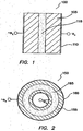
Fig. 1 illustrates a first dielectric configuration of the present invention having a parallel geometry; -
Fig. 2 illustrates a second dielectric configuration of the present invention having a cylindrical geometry; -
Fig. 3 illustrates three dielectric sections arranged to form a series capacitance network; -
Fig. 4 illustrates a circuit equivalent of the dielectric geometry ofFig. 3 ; -
Fig. 5 illustrates two titanate ceramic slabs coated on one side with a thin film of silver metal forming a conductive electrode surface on each; -
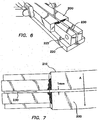
Fig. 6 illustrates a perspective view of the electrodes ofFig. 5 affixed to a polycarbonate beam support with a space between forming a fluid pathway; -
Fig. 7 illustrates a top view of the electrodes ofFig. 6 ; -
Fig. 8 illustrates an opposing beam support affixed to the other side of the arrangement illustrated inFigs. 6 and 7 ; -
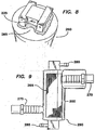
Fig. 9 illustrates one configuration of a high-impedance E-field device of the present invention; -
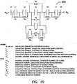
Fig. 10 illustrates an equivalent circuit diagram for the parallel plate geometry ofFigs. 6 and 7 ; -
Figs. 11 and 12 illustrate one exemplary system configuration according to the embodiments of the present invention; and -
Fig. 13 illustrates an equivalent circuit diagram for the configuration illustrated inFigs. 11 and 12 . - For the purposes of promoting an understanding of the principles in accordance with the embodiments of the present invention, reference will now be made to the embodiments illustrated in the drawings and specific language will be used to describe the same. It will nevertheless be understood that no limitation of the scope of the invention is thereby intended. Any alterations and further modifications of the inventive feature illustrated herein, and any additional applications of the principles of the invention as illustrated herein, which would normally occur to one skilled in the relevant art and having possession of this disclosure, are to be considered within the scope of the invention claimed.
- While embodiments of the present invention have many applications, one embodiment directed to biological cell electroporation is described herein. The term electroporation, sometimes electropermeabilization in patent and academic literature, is widely used to denote phenomena associated with the action of an electric field on the membrane of a living cell. Electroporation of cells suspended in a fluid electrolyte is important in the context of cellular biology, genetic engineering, drug therapy, as well as biotechnology processes such as pasteurization and sterilization. Depending on field intensity, exposure time, and wave-form shapes, impressed electric fields can cause either reversible or irreversible pore formation, as well as other structural defects in lipid membranes, including the membranes of bacteria, fungi, spores, virus, and mammalian (soma) cells. In the case of reversible electroporation, the phenomena is marked by a transient increase in membrane diffusion permeability, which has been used for decades for transfection of DNA, drugs, dyes, proteins, peptides, and other molecules. When the impressed electric field induces a critical transmembrane voltage (Φc ≈ 1 V for many bacteria types), for a sufficient period, pore formation and other membrane defects become irreversible causing cell death and/or permanent metabolic inactivation, viz. pasteurization or sterilization.
- Electroporation devices and methods for clinical and laboratory use have been available for decades, and can be readily purchased for transfection, pasteurization, and sterilization of small batch volumes (typically 1µl to 100 ml). Much work has been expended over the past two decades to adapt these clinical and laboratory methods to commercial applications that require continuous high flow rates instead of small batch volumes. Many devices and methods have been proposed, implemented, and patented, however, common to all the current and prior art is the use of low impedance electrically conductive electrodes coupled directly to the fluid being treated. This renders the equivalent circuit for such devices to a resistance network in the steady-state mode, accompanied by the parametric requisites of electric conduction current, ohmic heating, interface charge transfer, double layer formation, electrochemical reactions, and excessive energy consumption. These resistive load parametrics account for the ubiquitous use of pulsed waveforms employed in traditional electroporation devices. The use of pulsed wave forms (sometimes termed PEF), whether unipolar, bipolar, or other shapes, and regardless of rise and decay times, are all applied to mitigate the aforementioned undesirable effects of low impedance resistive networks common to current and prior art in this field. In the case of the attempts to adapt these techniques to a commercial pasteurization application, ohmic heating, undesirable electrochemical reactions, and excessive energy consumption have been particularly problematic.
- The embodiments of the present invention, coined High Impedance Electroporation by the inventors (hereinafter: HIE), mitigate many of the undesirable effects while proving to be as, or more, effective than prior systems and methods for both batch and high continuous flow rate applications.
-
Figs. 1 and 2 show a paralleldielectric configuration 100 and a cylindricaldielectric configuration 150, respectively, that may be used to facilitate the method embodiments of the present invention. Each configuration shows adielectric material conductive coating material - For capacitive elements forming series networks used to facilitate the embodiments of the present invention, charge displacement is conserved, and the potential gradient (voltage drop), along with the electric field, is distributed proportional to each material's permittivity prior to charge relaxation for each material section in the network.
Fig. 3 considers three dielectric sections 170,175 and 180 arranged to form aseries capacitance network 125.E-fields Fig. 4 shows a circuit diagram 140 representing thenetwork 125 ofFig. 3 . - Considering the arrangement depicted in
Fig. 3 , if the permittivity of sections Ci 170 and Ci 180 is significantly greater thanC 1 175, during the transient response of a pulse (step function), the potential across, and the E-field throughC i 170 and Ci 180 will be very small compared to the potential across, and the E-field throughsection C 1 175. This relationship effectively concentrates the total potential gradient available for field development in the center section, (C 1 175 in this example). The same relationship applies to networks comprised of 2, 4, or multiple dielectric section geometries. As a result, a much higher field stress can be impressed through the material under test or treatment than with the methods and devices of current and prior art. Additionally, use of dielectric electrodes with high volume resistivity limit electric current flow, ohmic heating, and energy consumption, as well as preempting undesirable electrochemical reactions at the electrode interfaces. - The inventors hereof demonstrated the effectiveness of the embodiments of the present invention via confidential experimentation. The following description describes the experimentation including the system and methodology utilized. However, those skilled in the art will understand that the scope of the present invention is not limited to the experimental systems and/or methodology utilized.
- Now referring to
Fig. 5 , two high impedancedielectric electrodes 200 fabricated of lead-magnesium-lead titanate ceramic are shown. Other materials, such as a high permittivity particulate/epoxy composite or materials having similar properties can also be used. The two titanateceramic slabs 200 were coated on one side with a thin film of silver metal forming aconductive surface 210. In one embodiment, the electrodes measured 10 mm thick by 10 mm wide by 100 mm long and the dielectric ceramic had the following electric material properties: - electric permittivity: 5.3e-08 [Fm-1] (relative dielectric constant εr = 6,000);
- volume resistivity: ≈ 1012 [Ω-cm]; and
- maximum allowable field stress: 9.0e+06 [Vm-1].
- As shown in
Figs. 6 and 7 , theelectrodes 200 were affixed to apolycarbonate beam support 220 with a space there between forming afluid pathway channel 230 measuring 1 mm deep by 10 mm wide by 100 mm long forming a fluid pathway or space volume of 1000mm3 or 1 ml. Afluid port 225 permits the inflow or outflow of subject fluid. Since the force of attraction imparted by the field between theelectrodes 200 is formidable when the system is charged, beam supports 220 were provided as structural strain relief for theceramic electrodes 200. Note that theelectrodes 200 are arranged to form a series capacitance network coupled to the test liquid being treated. Directional arrow A shown inFig. 7 depicts the direction of the generated E-field.Fig. 8 shows an opposing beam support 250 completing a liquid-tight fluid pathway. Now referring toFig. 9 , theelectrodes 200 and beam supports 220 were then fitted into a housing 260 (e.g., a 1-1/4" PVC pipe), which was filled with a highvoltage dielectric epoxy 265. Positive and negative high voltage cable guides 270, 275, respectively, and fluid tube fittings 280,285 were also affixed to form the final HIE device 300 (termed an abatis by the inventors hereof). - A liquid/bacteria suspension being treated was passed through the fluid pathway by conveyance tubes connected to the inlet tube fitting 280 and outlet tube fitting 285 as shown. Positive and negative
high voltage wires Fig. 11 ) were fed through the positive and negative cable guides 270, 275 and positioned in direct contact with the silverconductive surface 210 of eachrespective electrode 200 forming an electrical connection for charging the system.Fig. 10 shows an equivalent circuit diagram 310, and legend, for such a parallel plate geometry. -
Figs 11 and 12 show one complete system configuration 350. For safety reasons, theHIE device 300 was mounted on a high voltage dielectric bulkhead (e.g., ¼" polycarbonate plastic sheet), and wired to a 120kVDC power supply 310. A first 600 mlfluid supply beaker 320 was mounted vertically above theHIE device 300 such that, by means of gravity, the inoculated liquid would drain to thefluid inlet 280 and through theHIE device 300. A second 600ml beaker 325 was placed at a level below theHIE device 300 into which treated liquid would drain from thefluid outlet 285.Fig. 13 shows an equivalent circuit diagram 360 for thepower supply 310 andHIE device 300. - Prior to operating the system with a test liquid inoculated with bacteria, the
HIE device 300 was filled with sterile Tryptic Soy Both and its electrical properties were measured.Table # 1 shows predicted and measured values:Table #1 Ct [pF] Rt [Ω] E1 [Vm-1] Φa [ΔV] Is [Ǎ] Predicted 6.00E+02 2.50E+11 7.82E+07 1.00E+05 4.00E-07 Measured 6.52E+02 2.20E+11 8.50E+07 1.00E+05 4.55E-07 Where:
Ct total effective capacitance, [pF]; Picofarads
Rt total series resistance, [Ω]; ohms
E1 electric field through the liquid under test, [Vm-1]; volts per meter
Φa applied voltage (DC), [V]; volts
Is series current, [Ǎ]; amperes (transient displacement current not measured)HIE device 300, however, was on the order of 4.5e-07 amperes representing an extremely low current given the intense electric field generated (this figure does not include transient displacement current). The measured values represent an average of three (3) separate tests. The power supply was turned off and theHIE device 300 fully discharged between each measurement. - The system 350 for the electroporation test was operated at an applied voltage (Φa) of 10kV. The electric field E1 presented to the inoculated liquid under treatment at this voltage was 7.82e+06 Vm-1 or about 78 kV/cm. On the physical scale of E. coli bacteria, this field equates to 7.82 Vµm-1 and is sufficient to achieve the critical transmembrane potential (e.g., Φc ≈ 1 volt) often cited as a threshold for membrane electroporation. Electric conduction current (Ia) through the
HIE device 300 during the test was approximately 4.6e-08 Ǎ (0.046 microamperes). Average power consumption Pavg at theHIE device 300 only, not including cable and power supply losses, was on the order of 4.6e-04 W (460 microwatts). Since the volume of the treated liquid was 600 ml, and the total time for complete flow-through was approximately 480 seconds, the total energy dissipation Ut was on the order of 2.2e-01 J (221 millijoules), putting the specific energy consumption Us at 1.75e-03 kJ/IRlog (1.75 joules/liter-log reduction). - The cumulative exposure time (tx) was -800 ms, an average, against flow rate over the 480 second total process time. The bacterial load in the test liquid was reduced by 38% (kill fraction in terms of cfu/ml), or a log reduction of approximately -0.21 log10. The kill fraction stated is an average of seven intercepted samples taken at equal intervals during the test period. Although a - 0.21 log reduction is not significant for the purpose of commercial pasteurization, it is significant for the purpose of demonstrating the effectiveness of the embodiments of the present invention as applied to live cell electroporation. No attempt was made to detect or measure the extent of reversible electroporation (i.e. a transient increase in membrane permeability), but given the large kill fraction, electropermeabilization effects in the cohabitant survival fraction are immutable.
- A survey of commercial, academic, and patent literature covering the scope of electroporation devices, methods, and theory uncovered various applied voltages, field intensities, waveforms, pulse rates, rise/decay profiles, geometries, and fluid flow schemes. All of the current and prior art employ low impedance electrically conductive electrodes coupled directly to the liquid under treatment, thus rendering the equivalent circuit a predominately resistive load in the steady-state condition (there are elements of capacitance and inductance in all resistance networks, however, these circuit elements are not pertinent to this exam). Such is true for clinical, laboratory and commercial systems. However, the embodiments of the present invention comprise a series capacitance network. The following table presents an overview of critical electrical parameters for the operating electroporation devices and systems surveyed (the range of some values is broad, but still instructive):
Table #2 Φa E1 tp f p Us [kV] [Vm-1] [kVcm-1] [µs] [Hz] [kJ/IRlog] Minimum Value 5.00E+0 Reported < 0.1 2 0.005 0.001 100 25 Maximum Value 8.70E+0 1.00E+0 Reported 75 6 87 300 6 11,300 Where:
Φa applied voltage, [kV]; kilovolts
E1 field intensity, [Vm-1] and [kVcm-1]; volts per meter, & kilovolts per centimeter
tp pulse width, [µs]; microseconds
f p pulse frequency, [Hz]; hertz (as pulses per second, not cycles per second)
Us specific energy, [kJ/IRlog]; kilojoules per liter per log reduction - The data collected from the study encompass a wide range of both reversible (transient permeabilization) and irreversible (death) electroporation effects, a number of different bacteria types, and includes systems with coaxial (cylindrical) and parallel fluid pathway geometries, as well as both batch type and continuous flow schemes. However, the specific energy Us required by the device or method to affect the kill fraction attained was seldom cited (last column in Table #2). The survey conducted by the inventors, often requiring calculations extramural to the reports under study, revealed the magnitude of energy consumption versus kill fraction to be quite high as shown. By contrast, the
HIE electroporation device 300 fabricated for the instant demonstration expended a specific energy (Us) on the order of 1.75e-03 kJ/IRlog, some 4 orders of magnitude lower than the lowest specific energy (Us) reported, and 6 orders of magnitude less than the highest specific energy (Us) reported. This low energy consumption per liter per log reduction, owing to the high impedance of the embodiments of the present invention, is in addition to completely resolving the problems of fluid/electrode electrochemistry and ohmic heating presented by the current and prior art in this field. - Those skilled in the art will recognize that even though a time invariant DC voltage (square-wave pulse) was used to charge (energize) the
HIE device 300 in the instant demonstration, a time variant (AC) applied voltage can also be used. In addition, while a parallel plate geometry was employed for series capacitance geometry, other geometries, such as coaxial (cylindrical series capacitance), are equally applicable. - Further to the application of high impedance field generation to the electroporation of biological cells, the inventors have found a concordant action between the application of acoustic energy and electroporation. The acoustic energy can be applied via any desired means. For example, the acoustic energy can be applied 1) by action of a piezoelectric transducer attached to the
HIE device 300 in such a manner and in such a configuration as to impart the acoustic energy to the fluid in thepathway 230 or space concurrent with, concatenated between, and/or consequent to the applied electric field pulse or pulses; or, 2) by action of a piezoelectric response of thedielectric electrode 200 itself wherein the material chosen as the barrier material has suitable dielectric properties and is also a piezoelectric material. In such a case, the acoustic energy is imparted to the fluid under treatment or test concurrently (in both space and time) with the application of the applied potential. In this case, the acoustic energy has the same pulse duration time and pulse interval as the applied field. It is also possible that both means of applying the acoustic energy can be employed n a single system. That is, the dielectric electrode formed of a piezoelectric material acts to impart the electric field and the acoustic energy to the fluid under treatment simultaneously, while a second dedicated electroacoustic or mechanoacoustic transducer is positioned and configured to impart acoustic energy to the fluid under treatment either concurrently with, concatenated between, and/or consequent to the applied field. - The application of a pulsed acoustic longitudinal wave front to a biological cell during or immediately after being electroporated presents a periodic radiation pressure to the cell membrane. Since electroporation causes open pores to develop through the cellular membrane, the action of the radiation pressure, presented as a force perpendicular to the polar axis of the cell membrane, causes the cell to deform. Given the mass inertia of the cell and the viscosity of the supernatant, the cell flattens at the pole under the influence of the radiation force. As the cell membrane flattens at the pole (the polar axis being parallel to the radiation force vector), the incident angle between the radiation vector and portions of the membrane radial to the polar axis progressively decrease, that is, become more perpendicular to the force vector, thus advancing the flattening process. This process of flattening continues until the radiation force is overcome by the counter inertial and viscous forces at play and the cell begins to move. During the flattening period, however, either, or both, of two things occur relative to the cell's geometry: 1) the cell's internal volume decreases or 2) the membrane area increases (by stretching). The force resulting from the normal plan-wave longitudinal acoustic radiation pressure is a steady state phenomenon, hence the flattening action only occurs once, after which, the cell's shape tends to recover, and then the entire cell tends to move with the wave front. If the acoustic energy is pulsed however, the flattening/recovery action proceeds at the pulse rate, provided the pulse rate is presented at a lower frequency than the mechanical shape recovery relaxation time of the cell. Because the deformation periodically increases and decreases the internal volume of the cell, the result is a "pumping" action. The pumping action causes cytoplasmic fluid to be pumped out of the cell, as well as extra-cellular fluid (supernatant) to be pumped into the cell. The action serves to hasten or accelerate cellular paralysis leading to death and/or metabolic inactivation of the organism thus improving the efficiency and/or kill fraction for a given electric field intensity and field exposure period.
Claims (15)
- A high impendence system for subjecting a fluid to an electric field comprising:a pair of electrodes comprising a dielectric material (105, 155) wherein each electrode has at least one surface coated with an electrically conductive material (110, 160), and wherein said dielectric material (105, 155) forms a barrier separating the conductive coating (110, 160) from the fluid to which the electric field is to be applied;a fluid pathway or space (115, 165) in which, in use, the fluid is located formed between the pair of electrodes such that the conductive material (110, 160) is on an electrode surface not in contact with the fluid in the pathway or space (115, 165) ;a time variant, time invariant, or pulsed voltage source (310) applied across the electrodes; anda housing containing said pair of electrodes, said housing configured to maintain the fluid to which an electric field is to be applied in said pathway or space (115, 165).
- The system of claim 1 wherein the dielectric material (105, 155) has collectively a permittivity greater than 8.8e-11 Fm-1 @ ≤ 1.0KHz, a volume resistivity greater than 1.0E+04 Ωcm, and a maximum allowable electric field stress greater than 1.0 kVmm-1.
- The system of claim 1 wherein the electrodes are elongated, square in cross-section, and arranged in parallel.
- The system of claim 3 wherein the fluid pathway or space (115, 165) is between the electrodes.
- The system of claim 1 wherein the electrodes are elongated tubes having different diameters.
- The system of claim 5 wherein the electrodes are arranged in coaxial geometry with the smaller diameter electrode positioned within the larger diameter electrode forming an annular fluid pathway or space (165) there between.
- The system of claim 6 wherein an outer surface of the larger diameter electrode and an inner surface of the smaller diameter electrode is coated with an electrically conductive material (160).
- The system of claim 1 wherein the dielectric barrier material (105, 155) is a high permittivity ceramic, or other suitable dielectric material.
- The system of claim 1 further comprising means for applying pulsed acoustic energy to the fluid in the fluid pathway or space (115, 165).
- The system of claim 1 further comprising an electroacoustic or mechanoacoustic transducer operable to apply acoustic energy to the fluid in the fluid pathway or space (115, 165).
- The system of claim 1 wherein the electrodes are fabricated of a piezolelectric material operable to apply acoustic energy to the fluid in the fluid pathway or space (115, 165).
- A method of subjecting a fluid to an electric field comprising:forming a fluid pathway or space between a pair of electrodes wherein said electrodes comprise a dielectric material (105, 155) and wherein each electrode has at least one surface coated with an electrically conductive material (110, 160), and wherein said dielectric material (105, 155) forms a barrier separating the conductive coating (110, 160) from a fluid in the pathway or space (115, 165), and said conductive material (110, 160) placed on an electrode surface is not in contact with the fluid in the pathway or space (115, 165);housing said electrodes such that the fluid in the pathway or space (115, 165) is maintained in a static or dynamic state within said pathway or space (115, 165);applying a time variant, time invariant, or pulsed voltage source to each surface of the electrodes coated with the conductive material thereby creating an electric field across and through the pathway or space (115, 165); andcausing the fluid to enter the fluid pathway or space (115, 165) such that said fluid is exposed to the electric field and thereby treated or tested.
- The method of claim 12 further comprising selecting a dielectric material (105, 155) having permittivity of greater than 8.8e-11 Fm-1 @ ≤ 1.0 KHz, a volume resistivity greater than 1.0E+0 Ωcm and a maximum allowable electric field stress greater than 1.0 kVmm-1, thus electrically insulating the fluid in the fluid pathway or space thereby substantially preventing faradays current, electrical conduction current, and electrochemistry at the fluid/electrode interface, as well as ohmic heating through the subject material under test or treatment.
- The method of claim 12 further comprising two dielectric electrodes forming the fluid pathway or space between two parallel elongated electrodes wherein the electrodes have a square or rectangle cross-section, and where said parallel electrode geometry forms a series capacitance network with the fluid in the fluid pathway or space thereby increasing or concentrating the electric field through that fluid.
- The method of claim 12 further comprising applying acoustic energy to the fluid under treatment or test in the fluid pathway or space concurrently with, concatenated between, and/or consequent to the application of the electric field.
Applications Claiming Priority (3)
| Application Number | Priority Date | Filing Date | Title |
|---|---|---|---|
| US73288805P | 2005-11-02 | 2005-11-02 | |
| US11/551,584 US8226811B2 (en) | 2005-11-02 | 2006-10-20 | High impedance system for generating electric fields and method of use |
| PCT/US2006/042712 WO2007056027A1 (en) | 2005-11-02 | 2006-10-31 | High impedance system for generating electric fields and method of use |
Publications (3)
| Publication Number | Publication Date |
|---|---|
| EP1952133A1 EP1952133A1 (en) | 2008-08-06 |
| EP1952133A4 EP1952133A4 (en) | 2011-08-31 |
| EP1952133B1 true EP1952133B1 (en) | 2016-03-30 |
Family
ID=37994810
Family Applications (1)
| Application Number | Title | Priority Date | Filing Date |
|---|---|---|---|
| EP06827315.0A Not-in-force EP1952133B1 (en) | 2005-11-02 | 2006-10-31 | High impedance system for generating electric fields and method of use |
Country Status (11)
| Country | Link |
|---|---|
| US (2) | US8226811B2 (en) |
| EP (1) | EP1952133B1 (en) |
| JP (1) | JP5607304B2 (en) |
| KR (1) | KR101361498B1 (en) |
| AU (1) | AU2006311979B2 (en) |
| BR (1) | BRPI0618420A2 (en) |
| CA (1) | CA2628407C (en) |
| NZ (1) | NZ603542A (en) |
| RU (1) | RU2408006C2 (en) |
| UA (1) | UA95262C2 (en) |
| WO (1) | WO2007056027A1 (en) |
Families Citing this family (15)
| Publication number | Priority date | Publication date | Assignee | Title |
|---|---|---|---|---|
| US10996210B2 (en) | 2018-01-02 | 2021-05-04 | Transportation Ip Holdings, Llc | Vehicle system with sensor probe assembly for monitoring oil health |
| EP2461465B1 (en) | 2009-07-29 | 2018-12-19 | Thoratec Corporation | Rotation drive device and centrifugal pump device |
| EP2693609B1 (en) | 2011-03-28 | 2017-05-03 | Thoratec Corporation | Rotation and drive device and centrifugal pump device using same |
| CN102691498B (en) * | 2012-06-29 | 2014-11-26 | 西南石油大学 | Instrument for measuring electrical parameters of mud-while-drilling in horizontal well |
| CN102720490B (en) * | 2012-06-29 | 2014-11-26 | 西南石油大学 | Measuring method and measuring apparatus of vertical well drilling fluid gas-oil information |
| US20140221877A1 (en) * | 2013-02-01 | 2014-08-07 | Moshe Ein-Gal | Pressure-assisted irreversible electroporation |
| US10052420B2 (en) | 2013-04-30 | 2018-08-21 | Tc1 Llc | Heart beat identification and pump speed synchronization |
| US9623161B2 (en) | 2014-08-26 | 2017-04-18 | Tc1 Llc | Blood pump and method of suction detection |
| EP3256183A4 (en) | 2015-02-11 | 2018-09-19 | Tc1 Llc | Heart beat identification and pump speed synchronization |
| US10371152B2 (en) | 2015-02-12 | 2019-08-06 | Tc1 Llc | Alternating pump gaps |
| US10166318B2 (en) | 2015-02-12 | 2019-01-01 | Tc1 Llc | System and method for controlling the position of a levitated rotor |
| US10245361B2 (en) | 2015-02-13 | 2019-04-02 | Tc1 Llc | Impeller suspension mechanism for heart pump |
| US10117983B2 (en) | 2015-11-16 | 2018-11-06 | Tc1 Llc | Pressure/flow characteristic modification of a centrifugal pump in a ventricular assist device |
| US10835734B1 (en) | 2017-08-21 | 2020-11-17 | Wayne May | High and low impedance systems and methods for the generation and use of constant intensity electric fields |
| EP3666882A1 (en) | 2018-12-12 | 2020-06-17 | AIT Austrian Institute of Technology GmbH | Specific electroporation and lysis of eukaryotic cells |
Family Cites Families (28)
| Publication number | Priority date | Publication date | Assignee | Title |
|---|---|---|---|---|
| US2919235A (en) * | 1956-11-06 | 1959-12-29 | Paul S Roller | Electrolytic method and apparatus for the production of metal hydroxide |
| GB8621948D0 (en) * | 1986-09-11 | 1986-10-15 | Gibbs R W | Destroying bacteria |
| US4822470A (en) * | 1987-10-09 | 1989-04-18 | Baylor College Of Medicine | Method of and apparatus for cell poration and cell fusion using radiofrequency electrical pulses |
| US5134070A (en) * | 1990-06-04 | 1992-07-28 | Casnig Dael R | Method and device for cell cultivation on electrodes |
| US5234555A (en) * | 1991-02-05 | 1993-08-10 | Ibbott Jack Kenneth | Method and apparatus for ionizing fluids utilizing a capacitive effect |
| US5983131A (en) * | 1995-08-11 | 1999-11-09 | Massachusetts Institute Of Technology | Apparatus and method for electroporation of tissue |
| US5690978A (en) * | 1996-09-30 | 1997-11-25 | Ohio State University | High voltage pulsed electric field treatment chambers for the preservation of liquid food products |
| US6090617A (en) * | 1996-12-05 | 2000-07-18 | Entremed, Inc. | Flow electroporation chamber with electrodes having a crystalline metal nitride coating |
| GB9908681D0 (en) * | 1999-04-16 | 1999-06-09 | Central Research Lab Ltd | Apparatus for, and method of, introducing a substance into an object |
| US6455014B1 (en) * | 1999-05-14 | 2002-09-24 | Mesosystems Technology, Inc. | Decontamination of fluids or objects contaminated with chemical or biological agents using a distributed plasma reactor |
| US6689380B1 (en) * | 1999-05-17 | 2004-02-10 | Kevin S. Marchitto | Remote and local controlled delivery of pharmaceutical compounds using electromagnetic energy |
| US6692456B1 (en) * | 1999-06-08 | 2004-02-17 | Altea Therapeutics Corporation | Apparatus for microporation of biological membranes using thin film tissue interface devices, and method therefor |
| US6300108B1 (en) * | 1999-07-21 | 2001-10-09 | The Regents Of The University Of California | Controlled electroporation and mass transfer across cell membranes |
| US7192553B2 (en) * | 1999-12-15 | 2007-03-20 | Plasmasol Corporation | In situ sterilization and decontamination system using a non-thermal plasma discharge |
| GB9930718D0 (en) * | 1999-12-24 | 2000-02-16 | Central Research Lab Ltd | Apparatus for and method of making electrical measurements on objects |
| AU2001228841A1 (en) * | 2000-01-27 | 2001-08-07 | The Mollennium Laboratories | Molecule transferring device, auxiliary for molecule transferring device, and molecule transferring method |
| US6868289B2 (en) * | 2002-10-02 | 2005-03-15 | Standen Ltd. | Apparatus for treating a tumor or the like and articles incorporating the apparatus for treatment of the tumor |
| AU6475901A (en) | 2000-05-22 | 2001-12-03 | Merck And Company Inc | System and method for assessing the performance of a pharmaceutical agent delivery system |
| US6562386B2 (en) | 2001-05-07 | 2003-05-13 | Regents Of The University Of Minnesota | Method and apparatus for non-thermal pasteurization |
| US6911225B2 (en) * | 2001-05-07 | 2005-06-28 | Regents Of The University Of Minnesota | Method and apparatus for non-thermal pasteurization of living-mammal-instillable liquids |
| US7011790B2 (en) * | 2001-05-07 | 2006-03-14 | Regents Of The University Of Minnesota | Non-thermal disinfection of biological fluids using non-thermal plasma |
| EP1441774A2 (en) | 2001-11-02 | 2004-08-04 | Plasmasol Corporation | Sterilization and decontamination system using a plasma discharge and a filter |
| CA2487284A1 (en) | 2002-05-23 | 2003-12-04 | Gendel Limited | Ablation device |
| JP2004202086A (en) | 2002-12-26 | 2004-07-22 | Teikoku Seiyaku Co Ltd | Medicator for electroporation, and system and method of medication for electroporation |
| JP2004248653A (en) | 2003-02-22 | 2004-09-09 | Minoru Seki | Flow-type electrode device for electroporation and method for introducing substance into cell by using the same |
| JP4319427B2 (en) * | 2003-02-28 | 2009-08-26 | 株式会社東芝 | Medical ultrasonic irradiation equipment |
| WO2007021994A2 (en) | 2005-08-12 | 2007-02-22 | Maxcyte, Inc. | Electrode shielding for electroporation |
| WO2008104086A1 (en) * | 2007-03-01 | 2008-09-04 | Queen's University At Kingston | Planar electroporation apparatus and method |
-
2006
- 2006-10-20 US US11/551,584 patent/US8226811B2/en not_active Expired - Fee Related
- 2006-10-31 WO PCT/US2006/042712 patent/WO2007056027A1/en active Application Filing
- 2006-10-31 EP EP06827315.0A patent/EP1952133B1/en not_active Not-in-force
- 2006-10-31 CA CA2628407A patent/CA2628407C/en not_active Expired - Fee Related
- 2006-10-31 RU RU2008121962/28A patent/RU2408006C2/en not_active IP Right Cessation
- 2006-10-31 JP JP2008539011A patent/JP5607304B2/en not_active Expired - Fee Related
- 2006-10-31 BR BRPI0618420-0A patent/BRPI0618420A2/en not_active IP Right Cessation
- 2006-10-31 UA UAA200807394A patent/UA95262C2/en unknown
- 2006-10-31 KR KR1020087013250A patent/KR101361498B1/en not_active IP Right Cessation
- 2006-10-31 AU AU2006311979A patent/AU2006311979B2/en not_active Ceased
- 2006-10-31 NZ NZ603542A patent/NZ603542A/en not_active IP Right Cessation
-
2010
- 2010-04-29 US US12/769,872 patent/US8221596B2/en not_active Expired - Fee Related
Also Published As
| Publication number | Publication date |
|---|---|
| WO2007056027A1 (en) | 2007-05-18 |
| AU2006311979B2 (en) | 2013-01-24 |
| KR101361498B1 (en) | 2014-02-12 |
| US8221596B2 (en) | 2012-07-17 |
| EP1952133A4 (en) | 2011-08-31 |
| RU2408006C2 (en) | 2010-12-27 |
| US20070095648A1 (en) | 2007-05-03 |
| US8226811B2 (en) | 2012-07-24 |
| BRPI0618420A2 (en) | 2012-10-30 |
| KR20080080518A (en) | 2008-09-04 |
| RU2008121962A (en) | 2009-12-10 |
| NZ603542A (en) | 2013-03-28 |
| EP1952133A1 (en) | 2008-08-06 |
| US20110139608A1 (en) | 2011-06-16 |
| CA2628407A1 (en) | 2007-05-18 |
| JP2009515168A (en) | 2009-04-09 |
| JP5607304B2 (en) | 2014-10-15 |
| AU2006311979A1 (en) | 2007-05-18 |
| UA95262C2 (en) | 2011-07-25 |
| CA2628407C (en) | 2014-08-05 |
Similar Documents
| Publication | Publication Date | Title |
|---|---|---|
| EP1952133B1 (en) | High impedance system for generating electric fields and method of use | |
| JP2009515168A5 (en) | ||
| Gowrishankar et al. | Microdosimetry for conventional and supra-electroporation in cells with organelles | |
| US5326530A (en) | Energy-efficient electromagnetic elimination of noxious biological organisms | |
| US20200318056A1 (en) | Flow electroporation device | |
| Zhan et al. | Low-frequency ac electroporation shows strong frequency dependence and yields comparable transfection results to dc electroporation | |
| WO1997004858A1 (en) | Apparatus for the disinfection of liquids | |
| Krassowska et al. | Viability of cancer cells exposed to pulsed electric fields: the role of pulse charge | |
| Sridhara et al. | Evaluations of a mechanistic hypothesis for the influence of extracellular ions on electroporation due to high-intensity, nanosecond pulsing | |
| US11878300B2 (en) | Method and device for high field strength electrotransfection of microvescicles and cells | |
| MX2008005673A (en) | High impedance system for generating electric fields and method of use | |
| Sharma et al. | A mathematical model to expedite electroporation based vaccine development for COVID-19 | |
| Murauskas et al. | Electroporation cuvette with integrated electrodes for high gradient electric field generation | |
| CN101331392B (en) | High impedance system for generating electric fields and method of use | |
| Priya et al. | Modeling of electroporation and electric field investigation for a single cell dispersed in liquid foods | |
| US10835734B1 (en) | High and low impedance systems and methods for the generation and use of constant intensity electric fields | |
| Gaynor et al. | Physical modelling of electroporation in close cell-to-cell proximity environments | |
| US20240131513A1 (en) | Method and device for high field strength electrotransfection of microvescicles and cells | |
| Schmeer | Electroporative gene transfer | |
| Raptis et al. | In situ electroporation of large numbers of cells using minimal volumes of material | |
| Arslan et al. | Finite element analysis of electric field for in-vitro electropermeabilization | |
| Kasri et al. | Research Article Compact High-Voltage Pulse Generator for Pulsed Electric Field Applications: Lab-Scale Development | |
| KR20210015248A (en) | Device for electroporation | |
| Dong et al. | Electroporation introduction of diclofenac sodium into human erythrocytes and its determination | |
| Teissié et al. | Cell Membrane Electropermeabilization |
Legal Events
| Date | Code | Title | Description |
|---|---|---|---|
| PUAI | Public reference made under article 153(3) epc to a published international application that has entered the european phase |
Free format text: ORIGINAL CODE: 0009012 |
|
| 17P | Request for examination filed |
Effective date: 20080430 |
|
| AK | Designated contracting states |
Kind code of ref document: A1 Designated state(s): AT BE BG CH CY CZ DE DK EE ES FI FR GB GR HU IE IS IT LI LT LU LV MC NL PL PT RO SE SI SK TR |
|
| REG | Reference to a national code |
Ref country code: HK Ref legal event code: DE Ref document number: 1118910 Country of ref document: HK |
|
| A4 | Supplementary search report drawn up and despatched |
Effective date: 20110802 |
|
| RIC1 | Information provided on ipc code assigned before grant |
Ipc: G01N 27/02 20060101AFI20110727BHEP |
|
| DAX | Request for extension of the european patent (deleted) | ||
| GRAP | Despatch of communication of intention to grant a patent |
Free format text: ORIGINAL CODE: EPIDOSNIGR1 |
|
| INTG | Intention to grant announced |
Effective date: 20151016 |
|
| GRAS | Grant fee paid |
Free format text: ORIGINAL CODE: EPIDOSNIGR3 |
|
| GRAA | (expected) grant |
Free format text: ORIGINAL CODE: 0009210 |
|
| AK | Designated contracting states |
Kind code of ref document: B1 Designated state(s): AT BE BG CH CY CZ DE DK EE ES FI FR GB GR HU IE IS IT LI LT LU LV MC NL PL PT RO SE SI SK TR |
|
| REG | Reference to a national code |
Ref country code: GB Ref legal event code: FG4D |
|
| REG | Reference to a national code |
Ref country code: CH Ref legal event code: EP |
|
| REG | Reference to a national code |
Ref country code: AT Ref legal event code: REF Ref document number: 785919 Country of ref document: AT Kind code of ref document: T Effective date: 20160415 |
|
| REG | Reference to a national code |
Ref country code: IE Ref legal event code: FG4D |
|
| REG | Reference to a national code |
Ref country code: DE Ref legal event code: R096 Ref document number: 602006048483 Country of ref document: DE |
|
| REG | Reference to a national code |
Ref country code: NL Ref legal event code: FP |
|
| REG | Reference to a national code |
Ref country code: LT Ref legal event code: MG4D |
|
| PG25 | Lapsed in a contracting state [announced via postgrant information from national office to epo] |
Ref country code: GR Free format text: LAPSE BECAUSE OF FAILURE TO SUBMIT A TRANSLATION OF THE DESCRIPTION OR TO PAY THE FEE WITHIN THE PRESCRIBED TIME-LIMIT Effective date: 20160701 Ref country code: FI Free format text: LAPSE BECAUSE OF FAILURE TO SUBMIT A TRANSLATION OF THE DESCRIPTION OR TO PAY THE FEE WITHIN THE PRESCRIBED TIME-LIMIT Effective date: 20160330 |
|
| REG | Reference to a national code |
Ref country code: AT Ref legal event code: MK05 Ref document number: 785919 Country of ref document: AT Kind code of ref document: T Effective date: 20160330 |
|
| PG25 | Lapsed in a contracting state [announced via postgrant information from national office to epo] |
Ref country code: SE Free format text: LAPSE BECAUSE OF FAILURE TO SUBMIT A TRANSLATION OF THE DESCRIPTION OR TO PAY THE FEE WITHIN THE PRESCRIBED TIME-LIMIT Effective date: 20160330 Ref country code: LT Free format text: LAPSE BECAUSE OF FAILURE TO SUBMIT A TRANSLATION OF THE DESCRIPTION OR TO PAY THE FEE WITHIN THE PRESCRIBED TIME-LIMIT Effective date: 20160330 Ref country code: LV Free format text: LAPSE BECAUSE OF FAILURE TO SUBMIT A TRANSLATION OF THE DESCRIPTION OR TO PAY THE FEE WITHIN THE PRESCRIBED TIME-LIMIT Effective date: 20160330 |
|
| REG | Reference to a national code |
Ref country code: FR Ref legal event code: PLFP Year of fee payment: 11 |
|
| PG25 | Lapsed in a contracting state [announced via postgrant information from national office to epo] |
Ref country code: PL Free format text: LAPSE BECAUSE OF FAILURE TO SUBMIT A TRANSLATION OF THE DESCRIPTION OR TO PAY THE FEE WITHIN THE PRESCRIBED TIME-LIMIT Effective date: 20160330 Ref country code: IS Free format text: LAPSE BECAUSE OF FAILURE TO SUBMIT A TRANSLATION OF THE DESCRIPTION OR TO PAY THE FEE WITHIN THE PRESCRIBED TIME-LIMIT Effective date: 20160730 Ref country code: EE Free format text: LAPSE BECAUSE OF FAILURE TO SUBMIT A TRANSLATION OF THE DESCRIPTION OR TO PAY THE FEE WITHIN THE PRESCRIBED TIME-LIMIT Effective date: 20160330 |
|
| PG25 | Lapsed in a contracting state [announced via postgrant information from national office to epo] |
Ref country code: AT Free format text: LAPSE BECAUSE OF FAILURE TO SUBMIT A TRANSLATION OF THE DESCRIPTION OR TO PAY THE FEE WITHIN THE PRESCRIBED TIME-LIMIT Effective date: 20160330 Ref country code: SK Free format text: LAPSE BECAUSE OF FAILURE TO SUBMIT A TRANSLATION OF THE DESCRIPTION OR TO PAY THE FEE WITHIN THE PRESCRIBED TIME-LIMIT Effective date: 20160330 Ref country code: ES Free format text: LAPSE BECAUSE OF FAILURE TO SUBMIT A TRANSLATION OF THE DESCRIPTION OR TO PAY THE FEE WITHIN THE PRESCRIBED TIME-LIMIT Effective date: 20160330 Ref country code: RO Free format text: LAPSE BECAUSE OF FAILURE TO SUBMIT A TRANSLATION OF THE DESCRIPTION OR TO PAY THE FEE WITHIN THE PRESCRIBED TIME-LIMIT Effective date: 20160330 Ref country code: PT Free format text: LAPSE BECAUSE OF FAILURE TO SUBMIT A TRANSLATION OF THE DESCRIPTION OR TO PAY THE FEE WITHIN THE PRESCRIBED TIME-LIMIT Effective date: 20160801 Ref country code: CZ Free format text: LAPSE BECAUSE OF FAILURE TO SUBMIT A TRANSLATION OF THE DESCRIPTION OR TO PAY THE FEE WITHIN THE PRESCRIBED TIME-LIMIT Effective date: 20160330 |
|
| PG25 | Lapsed in a contracting state [announced via postgrant information from national office to epo] |
Ref country code: IT Free format text: LAPSE BECAUSE OF FAILURE TO SUBMIT A TRANSLATION OF THE DESCRIPTION OR TO PAY THE FEE WITHIN THE PRESCRIBED TIME-LIMIT Effective date: 20160330 Ref country code: BE Free format text: LAPSE BECAUSE OF FAILURE TO SUBMIT A TRANSLATION OF THE DESCRIPTION OR TO PAY THE FEE WITHIN THE PRESCRIBED TIME-LIMIT Effective date: 20160330 |
|
| REG | Reference to a national code |
Ref country code: DE Ref legal event code: R097 Ref document number: 602006048483 Country of ref document: DE |
|
| PG25 | Lapsed in a contracting state [announced via postgrant information from national office to epo] |
Ref country code: DK Free format text: LAPSE BECAUSE OF FAILURE TO SUBMIT A TRANSLATION OF THE DESCRIPTION OR TO PAY THE FEE WITHIN THE PRESCRIBED TIME-LIMIT Effective date: 20160330 |
|
| PLBE | No opposition filed within time limit |
Free format text: ORIGINAL CODE: 0009261 |
|
| STAA | Information on the status of an ep patent application or granted ep patent |
Free format text: STATUS: NO OPPOSITION FILED WITHIN TIME LIMIT |
|
| 26N | No opposition filed |
Effective date: 20170103 |
|
| PG25 | Lapsed in a contracting state [announced via postgrant information from national office to epo] |
Ref country code: SI Free format text: LAPSE BECAUSE OF FAILURE TO SUBMIT A TRANSLATION OF THE DESCRIPTION OR TO PAY THE FEE WITHIN THE PRESCRIBED TIME-LIMIT Effective date: 20160330 |
|
| REG | Reference to a national code |
Ref country code: CH Ref legal event code: PL |
|
| REG | Reference to a national code |
Ref country code: IE Ref legal event code: MM4A |
|
| PG25 | Lapsed in a contracting state [announced via postgrant information from national office to epo] |
Ref country code: LI Free format text: LAPSE BECAUSE OF NON-PAYMENT OF DUE FEES Effective date: 20161031 Ref country code: CH Free format text: LAPSE BECAUSE OF NON-PAYMENT OF DUE FEES Effective date: 20161031 |
|
| PG25 | Lapsed in a contracting state [announced via postgrant information from national office to epo] |
Ref country code: LU Free format text: LAPSE BECAUSE OF NON-PAYMENT OF DUE FEES Effective date: 20161031 |
|
| REG | Reference to a national code |
Ref country code: FR Ref legal event code: PLFP Year of fee payment: 12 |
|
| PGFP | Annual fee paid to national office [announced via postgrant information from national office to epo] |
Ref country code: FR Payment date: 20170918 Year of fee payment: 12 |
|
| PG25 | Lapsed in a contracting state [announced via postgrant information from national office to epo] |
Ref country code: IE Free format text: LAPSE BECAUSE OF NON-PAYMENT OF DUE FEES Effective date: 20161031 |
|
| PGFP | Annual fee paid to national office [announced via postgrant information from national office to epo] |
Ref country code: DE Payment date: 20171025 Year of fee payment: 12 |
|
| PGFP | Annual fee paid to national office [announced via postgrant information from national office to epo] |
Ref country code: NL Payment date: 20171016 Year of fee payment: 12 Ref country code: GB Payment date: 20171025 Year of fee payment: 12 |
|
| REG | Reference to a national code |
Ref country code: HK Ref legal event code: WD Ref document number: 1118910 Country of ref document: HK |
|
| PG25 | Lapsed in a contracting state [announced via postgrant information from national office to epo] |
Ref country code: HU Free format text: LAPSE BECAUSE OF FAILURE TO SUBMIT A TRANSLATION OF THE DESCRIPTION OR TO PAY THE FEE WITHIN THE PRESCRIBED TIME-LIMIT; INVALID AB INITIO Effective date: 20061031 Ref country code: CY Free format text: LAPSE BECAUSE OF FAILURE TO SUBMIT A TRANSLATION OF THE DESCRIPTION OR TO PAY THE FEE WITHIN THE PRESCRIBED TIME-LIMIT Effective date: 20160330 |
|
| PG25 | Lapsed in a contracting state [announced via postgrant information from national office to epo] |
Ref country code: TR Free format text: LAPSE BECAUSE OF FAILURE TO SUBMIT A TRANSLATION OF THE DESCRIPTION OR TO PAY THE FEE WITHIN THE PRESCRIBED TIME-LIMIT Effective date: 20160330 Ref country code: MC Free format text: LAPSE BECAUSE OF FAILURE TO SUBMIT A TRANSLATION OF THE DESCRIPTION OR TO PAY THE FEE WITHIN THE PRESCRIBED TIME-LIMIT Effective date: 20160330 |
|
| PG25 | Lapsed in a contracting state [announced via postgrant information from national office to epo] |
Ref country code: BG Free format text: LAPSE BECAUSE OF FAILURE TO SUBMIT A TRANSLATION OF THE DESCRIPTION OR TO PAY THE FEE WITHIN THE PRESCRIBED TIME-LIMIT Effective date: 20160330 |
|
| REG | Reference to a national code |
Ref country code: DE Ref legal event code: R119 Ref document number: 602006048483 Country of ref document: DE |
|
| REG | Reference to a national code |
Ref country code: NL Ref legal event code: MM Effective date: 20181101 |
|
| GBPC | Gb: european patent ceased through non-payment of renewal fee |
Effective date: 20181031 |
|
| PG25 | Lapsed in a contracting state [announced via postgrant information from national office to epo] |
Ref country code: NL Free format text: LAPSE BECAUSE OF NON-PAYMENT OF DUE FEES Effective date: 20181101 Ref country code: DE Free format text: LAPSE BECAUSE OF NON-PAYMENT OF DUE FEES Effective date: 20190501 |
|
| PG25 | Lapsed in a contracting state [announced via postgrant information from national office to epo] |
Ref country code: FR Free format text: LAPSE BECAUSE OF NON-PAYMENT OF DUE FEES Effective date: 20181031 |
|
| PG25 | Lapsed in a contracting state [announced via postgrant information from national office to epo] |
Ref country code: GB Free format text: LAPSE BECAUSE OF NON-PAYMENT OF DUE FEES Effective date: 20181031 |