EP1948057B1 - Systems for electrode contact assessment - Google Patents
Systems for electrode contact assessment Download PDFInfo
- Publication number
- EP1948057B1 EP1948057B1 EP06836608A EP06836608A EP1948057B1 EP 1948057 B1 EP1948057 B1 EP 1948057B1 EP 06836608 A EP06836608 A EP 06836608A EP 06836608 A EP06836608 A EP 06836608A EP 1948057 B1 EP1948057 B1 EP 1948057B1
- Authority
- EP
- European Patent Office
- Prior art keywords
- electrode
- piezoelectric sensor
- contact
- tissue
- sensors
- Prior art date
- Legal status (The legal status is an assumption and is not a legal conclusion. Google has not performed a legal analysis and makes no representation as to the accuracy of the status listed.)
- Not-in-force
Links
Images


Classifications
-
- A—HUMAN NECESSITIES
- A61—MEDICAL OR VETERINARY SCIENCE; HYGIENE
- A61B—DIAGNOSIS; SURGERY; IDENTIFICATION
- A61B18/00—Surgical instruments, devices or methods for transferring non-mechanical forms of energy to or from the body
- A61B18/04—Surgical instruments, devices or methods for transferring non-mechanical forms of energy to or from the body by heating
- A61B18/12—Surgical instruments, devices or methods for transferring non-mechanical forms of energy to or from the body by heating by passing a current through the tissue to be heated, e.g. high-frequency current
- A61B18/14—Probes or electrodes therefor
- A61B18/1492—Probes or electrodes therefor having a flexible, catheter-like structure, e.g. for heart ablation
-
- A—HUMAN NECESSITIES
- A61—MEDICAL OR VETERINARY SCIENCE; HYGIENE
- A61B—DIAGNOSIS; SURGERY; IDENTIFICATION
- A61B5/00—Measuring for diagnostic purposes; Identification of persons
- A61B5/68—Arrangements of detecting, measuring or recording means, e.g. sensors, in relation to patient
- A61B5/6846—Arrangements of detecting, measuring or recording means, e.g. sensors, in relation to patient specially adapted to be brought in contact with an internal body part, i.e. invasive
- A61B5/6847—Arrangements of detecting, measuring or recording means, e.g. sensors, in relation to patient specially adapted to be brought in contact with an internal body part, i.e. invasive mounted on an invasive device
- A61B5/6852—Catheters
-
- A—HUMAN NECESSITIES
- A61—MEDICAL OR VETERINARY SCIENCE; HYGIENE
- A61B—DIAGNOSIS; SURGERY; IDENTIFICATION
- A61B5/00—Measuring for diagnostic purposes; Identification of persons
- A61B5/68—Arrangements of detecting, measuring or recording means, e.g. sensors, in relation to patient
- A61B5/6846—Arrangements of detecting, measuring or recording means, e.g. sensors, in relation to patient specially adapted to be brought in contact with an internal body part, i.e. invasive
- A61B5/6885—Monitoring or controlling sensor contact pressure
-
- A—HUMAN NECESSITIES
- A61—MEDICAL OR VETERINARY SCIENCE; HYGIENE
- A61B—DIAGNOSIS; SURGERY; IDENTIFICATION
- A61B90/00—Instruments, implements or accessories specially adapted for surgery or diagnosis and not covered by any of the groups A61B1/00 - A61B50/00, e.g. for luxation treatment or for protecting wound edges
- A61B90/06—Measuring instruments not otherwise provided for
- A61B2090/064—Measuring instruments not otherwise provided for for measuring force, pressure or mechanical tension
- A61B2090/065—Measuring instruments not otherwise provided for for measuring force, pressure or mechanical tension for measuring contact or contact pressure
Definitions
- the instant invention is directed toward an electrode contact sensing system comprising one or more electro-mechanical sensor, such as a piezoelectric sensor, for assessing catheter contact with a moving surface (e.g., the heart wall) for ablation procedures.
- electro-mechanical sensor such as a piezoelectric sensor
- lesions may be formed in tissue if the depth and location of the lesions being formed can be controlled. In particular, it can be desirable to elevate tissue temperature to around 50°C until lesions are formed via coagulation necrosis, which changes the electrical properties of the tissue. For example, lesions may be formed at specific locations in cardiac tissue via coagulation necrosis to lessen or eliminate undesirable atrial fibrillations.
- Electrode-tissue contact is not readily determined using conventional fluoroscopy techniques. Instead, the physician determines electrode-tissue contact based on his/her experience using the electrode catheter. Such experience only comes with time, and may be quickly lost if the physician does not use the electrode catheter on a regular basis.
- the beating of the heart further complicates matters, making it difficult to assess and maintain sufficient contact pressure between the electrode and the tissue for a sufficient length of time to form a desired lesion.
- US-A1-2002/0123749 discloses a catheter having an ablation electrode and one or more pressure sensors positioned within a tissue-contacting area of the catheter shaft for providing pressure data indicative of the pressure exerted on the distal portion of the catheter.
- the pressure sensor(s) may comprise a piezoelectric transducer electrically coupled to a lead that passes through the ablation electrode and the catheter shaft to a microprocessor, which generates an indication of the state of electrode/tissue contact during a catheter procedure.
- WO95/10978 discloses the preamble of independent claim 1
- US2003130615 discloses an electrode contact sensing system wherein three sensors are arranged on a disc shaped support structure. It is an object of the present invention to provide an improved electrode contact sensing system. This object is achieved by the invention of claim 1. Further embodiments of the invention are recited in the dependent claims.
- Electrode contact with a surface (e.g., the heart wall) for tissue ablation procedures.
- a surface e.g., the heart wall
- This stress may be measured by implementing one or more electro-mechanical sensors, such as a piezoelectric sensor, coupled to the electrode.
- the piezoelectric sensor(s) generates a voltage signal and charge corresponding to stress of the electrode.
- a piezoelectric sensor is operatively associated with an electrode housed within a catheter shaft.
- a plurality of piezoelectric sensors are provided within the electrode catheter. Output from the piezoelectric sensor(s) enables a user (e.g., a physician or technician) to position the electrode catheter against a target tissue with the desired amount of pressure for the ablation procedure.
- An exemplary electrode contact sensing system comprises an electrode housed within a distal portion of a catheter shaft. At least one piezoelectric sensor is operatively associated with the electrode within the catheter shaft. The at least one piezoelectric sensor is responsive to stress of the electrode by generating electrical signals corresponding to the amount of stress. The system also includes an output device electrically connected to the at least one piezoelectric sensor. The output device receives the electrical signals for assessing a level of contact between the electrode and a tissue.
- Electrode-tissue contact for tissue ablation may be assessed by generating piezoelectric signals in response to stress of an electrode housed within a distal portion of a flexible catheter, and assessing a level of contact between the electrode and a moving tissue based on the piezoelectric signals.
- Output may be conveyed to the user in real-time (e.g., at a display device or other interface) so that the user can properly position the electrode on the target tissue with the desired level of contact for the ablation procedure.
- the user may increase contact pressure if the output indicates insufficient contact.
- the user may reduce contact pressure if the output indicates too much contact.
- variations of the mechanical load on the sensor are indicative of contact stress between said electrode and the tissue, and the output device is adapted to indicate to the user the contact stress between the electrode and the tissue.
- the variable electrical signal may have a strength that is proportional to the contact stress.
- the variable electrical signal may have an amplitude that is proportional to the magnitude of the contact stress.
- the variable electrical signal may have a periodicity that, e.g., corresponds to the periodicity of contact stress.
- the inventive electrode contacting system may be used to sense electrode-tissue contact by contacting a tissue with the electrode provided at the distal portion of the catheter, generating electric signals in the electro-mechanical sensor in response to contact stress of the electrode with the tissue and outputting the electrical signals to a monitoring device.
- contact stresses between the electrode and tissue are assessed based on the electric signals.
- Contact may be assessed based on the strength, the amplitude or the periodicity of the electric signals.
- FIG. 1a-b illustrate exemplary contact between an electrode and a moving target tissue.
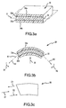
- FIG. 2 is perspective view of an exemplary electrode with a piezoelectric sensor.
- FIG. 2a is a perspective view of an exemplary supporting structure for mounting a piezoelectric sensor to the electrode as shown in Figure 2 .
- FIG. 3a is a sectional view of an exemplary piezoelectric sensor which may be implemented for use with the electrode.
- the piezoelectric sensor is shown in exaggerated form as it may respond to various stresses.
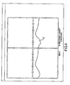
- FIG. 4 shows exemplary output of an oscilloscope showing a waveform corresponding to electrical signals generated by a piezoelectric sensor.
- FIG. 5a-e are perspective views showing alternative embodiments for operatively associating at least one piezoelectric sensor with an electrode.
- FIG. 6a-c are cross-sectional views showing more alternative embodiments for operatively associating at least one piezoelectric sensor with an electrode, not showing all features of the invention.
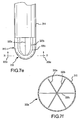
- FIG. 7a-g are perspective views and corresponding cross-sectional views showing more alternative embodiments for operatively associating at least one piezoelectric sensor with an electrode, not showing all features of the invention.
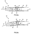
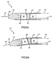
- FIG. 8a-h are cross-sectional views showing more alternative embodiments for operatively associating at least one piezoelectric sensor with an electrode, and corresponding cross-sectional views showing exemplary response of the piezoelectric sensor to stress of the electrode, not showing all features of the invention.
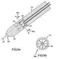
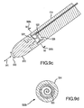
- FIG. 9a-f are side and corresponding cross-sectional views showing more alternative embodiment for operatively associating at least one piezoelectric sensor with an electrode, not showing all features of the invention.
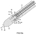
- FIG. 10a is a cross-sectional view showing another alternative embodiment for operatively associating at least one piezoelectric sensor with an electrode, not showing all features of the invention.
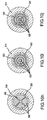
- FIG. 10b-j are cross-sectional views showing alternative embodiments of the piezoelectric sensor shown in FIG. 10a , not showing all features of the invention.
- Exemplary embodiments of a tissue ablation system of use to assess contact between an electrode in a catheter and a tissue are depicted in the figures.
- Exemplary systems comprise an electrode which may be inserted into the patient using a catheter, e.g., for forming ablative lesions inside the patient's heart.
- a user e.g., the patient's physician or a technician
- the user guided by a real-time fluoroscopy imaging device, moves the catheter into the patient's heart.
- electrodes at the distal portion of the catheter may be implemented to electrically map the myocardium (i.e., muscular tissue in the heart wall) and locate a target tissue. After locating the target tissue, the user must move the catheter into contact with the target tissue before applying ablative energy from the same or other electrodes in the catheter to form an ablative lesion or lesions. The level of contact is often critical to form sufficiently deep ablative lesions on the target tissue without damaging surrounding tissue in the heart.
- the system may include one or more electro-mechanical sensors, such as a piezoelectric sensor, which generate electric signals in response to the electrode coming into contact with a surface (e.g., target tissue within the beating heart).
- a surface e.g., target tissue within the beating heart.
- embodiments of the present invention provide a number of advantages, including, for example, the ability to apply a reasonable amount of ablative energy to a target tissue while mitigating tissue contact problems.
- the invention also facilitates enhanced tissue contact in difficult environments (e.g., during lesion formation on a moving surface inside a beating heart).
- FIG. 1a and 1b illustrate exemplary contact between an electrode 10 and a target tissue 12 (e.g., myocardium).
- Electrode 10 may be provided in a flexible shaft 14 of the catheter 16.
- the flexible catheter shaft 14 may be made of a plastic or other suitable material which enables the electrode 10 to be readily inserted into the patient's heart through the blood vessels, and to be moved or deflected by movement of an adjacent tissue (e.g., target tissue 12).
- the electrode 10 may be electrically connected via suitable wiring through the catheter shaft 14 to a generator (not shown), such as, e.g., a radio frequency (RF) generator.
- a generator such as, e.g., a radio frequency (RF) generator.
- the electrode 10 is thus operable to emit electrical energy (e.g., RF current) near the tip of the electrode 10 for forming thermal lesion(s) on the target tissue during ablation procedures.
- a user may operate a handle portion (not shown) of the catheter 16 to manually position the electrode 10 inside the patient's heart so that the electrode 10 is in contact with the target tissue 12.
- the electrode 10 is shown having little, if any, contact with the target tissue 12, e.g., the electrode 10 may be "floating" adjacent the target tissue 12 as the user is positioning the electrode 10 using catheter 16 in the heart for an ablation procedure.
- the electrode 10 is shown in contact with the target tissue 12.
- the electrode 10 When the electrode 10 is in sufficient or "good” contact with the target tissue 12, the electrode 10 may be stressed or deflected by contact with the target tissue 12 generally in the directions illustrated by arrows 18. Stress or deflection of the electrode 10 may be measured in real-time using at least one piezoelectric sensor 20 to assess contact between the electrode 10 and the target tissue 12, as described more fully below.
- FIG. 1b the contact and motion illustrated by FIG. 1b is shown for purposes of illustration and is not intended to be limiting. Other contact and motion may also exist and/or be desired by the user.
- the definition of sufficient or "good” contact may depend at least to some extent on various operating conditions, such as, e.g., the type of target tissue, desired depth of the ablation lesion, and power and duration of the applied RF energy, to name only a few examples.
- FIG. 2 is a perspective view of an exemplary electrode 10 operatively associated with a piezoelectric sensor 20.
- the piezoelectric sensor 20 is provided on a supporting structure 22 shaped as a tripod.
- FIG. 2a is a perspective view of an exemplary supporting structure 22 shaped as a tripod with piezoelectric sensor 20 provided thereon.
- the piezoelectric sensor 20 may be formed as a single piece having arms 20a-c connected by a collar 21 and extending at least partially down each leg 22a-c of the supporting structure 22.
- the supporting structure 22 is mounted directly to the electrode 20 on neck portion 24, as shown in Figure 2 .
- the supporting structure 22 with piezoelectric sensor 20 may be provided within an insulated cavity or compliant section 26 of the catheter shaft 14.
- the compliant section 26 may serve as a low pass mechanical filter. That is, the compliant section 26 attenuates high frequency "noise" signals caused, e.g., by minor vibrations from intermittent contact during positioning of the electrode 10 adjacent the target tissue 12. Accordingly, high frequency noise signals are damped, or even non-existent, as output for the user.
- Electrical wiring 28 may be connected to the piezoelectric sensor 20 (e.g., as illustrated by connection 28'). Electrical wiring 29 may also be connected to a ground (e.g., as illustrated by connection 29' to the leg 22c of the supporting structure 22 where the supporting structure is an electrical conductor). It is noted that only one wire needs to be connected to the piezoelectric sensor 20 (and one wire to ground) in this disclosure because the piezoelectric sensor 20 is formed as a single piece.
- the wires 28-29 may extend through the catheter shaft 14 to deliver electrical signals from the piezoelectric sensor 20 to a data acquisition/processing/output device (not shown), such as, e.g., an echocardiogram (ECG) device.
- a wireless connection may be implemented, e.g., by providing a transmitter in the catheter and a receiver in association with the data acquisition/processing/output device.
- the piezoelectric sensor 20 responds to electrode-tissue contact stresses by generating electrical energy (e.g., a voltage or charge). Accordingly, when the electrode 10 is positioned in contact with the target tissue 12, piezoelectric sensor 20 generates an electrical signal corresponding to stress of the electrode 10. The resulting electrical signal may be processed and/or otherwise output for the user so that the user is able to determine when the electrode 10 is positioned with the desired level of contact with the target tissue 12.
- electrical energy e.g., a voltage or charge
- piezoelectric sensors which generate electrical energy in response to applied mechanical stress are well-understood in the electro-mechanical arts.
- piezoelectric sensors comprise a piezoelectric material which contains positive and negative electrical charges. In a neutral or "non-stressed" state, these electrical charges are symmetrically distributed in the piezoelectric material such that the material exhibits an overall neutral electrical charge.
- a mechanical stress e.g., flexure, pressure, and/or tension
- disturbs the symmetrical distribution of electrical charges thereby generating electrical energy across the material.
- Even minor deformation of some piezoelectric materials may generate a measurable voltage signal. Operation of piezoelectric material may be better understood with brief reference to FIG. 3a-c
- FIG. 3a is a cross-sectional perspective view of a portion of an exemplary piezoelectric sensor 20 which may be implemented for use with the electrode 10.
- the piezoelectric sensor 20 is shown in exaggerated form as it may respond to various stresses, wherein FIG. 3b is a side-view of the piezoelectric sensor 20 shown in FIG. 3a, and FIG. 3c is a top-view of the piezoelectric sensor 20 shown in FIG. 3a .
- the piezoelectric sensor 20 may be a laminated sensor, having a plurality of laminated layers. Although not required, laminating the sensor increases its sensitivity.
- the laminated layers may comprise a piezoelectric material 30 "sandwiched" between metal layers 32a and 32b and protective coating 34a and 34b.
- Metal layers 32a and 32b may be any suitable metal, e.g., a thin layer of silver ink.
- the metal layers 32a and 32b serve to collect electrical charge generated by the piezoelectric material 30, e.g., for delivery as electrical signals via electrical wiring to a data acquisition/processing/output device.
- Metal layers 32a and 32b serve to collect electrical energy in response to stress of the piezoelectric material 30.
- Piezoelectric material such as PVDF (Kynar)
- PVDF Kynar
- Protective coating 34a and 34b may be any suitable material, e.g., Mylar®.
- the laminated layers of piezoelectric sensor 20 are not limited to any particular material and/or configuration.
- the piezoelectric sensor 20 is not limited to use with separate metal layers 32a and 32b.
- the piezoelectric sensor 20 limited to the generally rectangular configuration shown in FIG. 3 a.
- the piezoelectric material 30 may comprise a thin, flexible, polymer-based material.
- One such piezoelectric film is a polyvinylidene fluoride (PVDF) film commercially available from the Sensor Products Division of Measurement Specialties, Inc. (Norristown, Pennsylvania). This PVDF film is approximately 28 ⁇ m thick, enabling the PVDF film to be readily housed within the catheter shaft 14.
- PVDF polyvinylidene fluoride
- other common piezoelectric materials such as lead zirconate titanate (PZT) has a dynamic stress constant (g 31 ) of 10 x 10 -3 Vm/N
- barium titanium oxide (BaTiO 3 ) has a dynamic stress constant (g 31 ) of 5 x 10 -3 Vm/N. Accordingly, the PVDF film is very sensitive, exhibiting a relatively high voltage response to relatively small mechanical stresses, and is therefore well-suited for measuring dynamic stresses and strains.
- piezoelectric sensor 20 described above with reference to FIG. 3a is for purposes of illustration and not intended to be limiting. Other piezoelectric sensors may also be implemented, and are not limited to laminated piezoelectric film. Nor are piezoelectric sensors limited to use with any particular type or size of piezoelectric material. Selection of piezoelectric sensor 20 for use with the electrode 10 may be application-specific and depend at least in part on one or more design considerations, such as, but not limited to, the desired sensitivity and/or spatial constraints for housing the piezoelectric sensor.
- Piezoelectric sensor 20 is shown in FIG. 3a in a neutral state.
- the piezoelectric material 30 is not subject to any stresses or strains. Accordingly, the electrical charges are symmetrically distributed on either side of the neutral plane N in the piezoelectric material 30 such that the material exhibits an overall neutral electrical charge.
- the most widely used coefficients, d3n (for charge) and g3n (for voltage), possess two subscripts. The first refers to the electrical axis, while the second subscript refers to the mechanical axis. Because piezoelectric film is thin, the electrodes are only applied to the top and bottom film surfaces. Accordingly, the electrical axis is always referred to as "3", as the charge or voltage is always transferred through the thickness (n 3) of the film.
- the mechanical axis can be either 1, 2, or 3, because the stress can be applied to any of these axes.
- piezoelectric film is used in the mechanical 1 direction for low frequency sensing and actuation ( ⁇ 100KHz) and in the mechanical 3 direction for high ultrasound sensing and actuation (> 100KHz). These stresses can be better understood with reference to FIG. 3b and 3c .
- FIG. 3b is a side-view of the piezoelectric sensor 20 shown in FIG. 3a .
- the piezoelectric sensor 20 is shown in exaggerated form as it may respond to transverse stresses applied generally in the direction of arrow 36.
- the piezoelectric material 30 undergoes transverse strain relative to its neutral state, as illustrated by arrows A1 and A2.
- the piezoelectric sensor 20 may also respond to bending stresses.
- the piezoelectric material 30 undergoes flexural strain relative to its neutral state, as illustrated by arrows B1 and B2.
- FIG. 3c is a top-view of the piezoelectric sensor 20 shown in FIG. 3a .
- the piezoelectric sensor 20 is shown in exaggerated form as it may respond to stress distribution applied generally in the direction of arrows 37.
- the piezoelectric material 30 is longitudinally strained relative to its neutral state, as illustrated by arrows C 1 and C2.
- this electrical energy may be collected by metal layers 32a, 32b, e.g., for delivery as an electrical signal via electrical wiring through the catheter shaft 14 to a signal conditioning/data acquisition/processing/output device (not shown).
- piezoelectric sensor 20 shown mounted to the electrode 10 in Figure 2 , it can be readily seen that piezoelectric sensor 20 provided on supporting structure 22 and mounted to the electrode 10 is stressed or strained due to stress on the electrode 10 (e.g., in the directions illustrated by arrows 40 and/or 41).
- the piezoelectric sensor 20 responds by generating electrical (voltage) signals. These electrical signals may be viewed by the user, e.g., as output on an electrical monitoring device.
- FIG. 4 is exemplary output of an oscilloscope showing waveform 42 corresponding to electrical signals generated by a piezoelectric sensor (e.g., piezoelectric sensor 20 in FIG. 2 ) when it is coupled to an electrode in contact with a moving tissue, such as the myocardium.
- output such as waveform 42 may be displayed for a user, e.g., as a waveform on an ECG device.
- the signal strength (e.g., amplitude) from the piezoelectric sensor 20 is proportional to the amount of stress of the electrode 10, and therefore can be used to determine if the electrode 10 is in good contact with a tissue (e.g., the myocardium). If the electrode 10 is not in contact with the target tissue, there are no peaks in the resulting waveform 42 (or the peaks are intermittent). On the other hand, a strong correlation between the heartbeat and output by the piezoelectric sensor indicates that the electrode 10 is in good contact with the moving target tissue.
- a tissue e.g., the myocardium
- Signal periodicity is also a strong indicator of dynamic contact assessment. For example, if the period between heartbeats corresponds well with the period output by the piezoelectric sensor 20, the electrode 10 is moving in response to the heartbeat (and not some other reason). Accordingly, the user may use this feedback to increase or decrease contact of the catheter with the moving heart wall to achieve the desired contact.
- any suitable analog and/or digital device may be implemented for indicating electrode-tissue contact to a user.
- the electrical signals generated by piezoelectric sensor 20 may be further characterized using a suitable processing device such as, but not limited to, a desktop or laptop computer.
- a suitable processing device such as, but not limited to, a desktop or laptop computer.
- Such processing device may be implemented to receive the voltage or charge signal generated by the piezoelectric sensor and convert it to a corresponding contact condition for the electrode 10 and output for the user, e.g., at a display device.
- the output device is not limited to a display device.
- the electrode-tissue contact may be output to the user as an audio signal or tactile feedback (e.g., vibrations) on the handle of the catheter.
- circuitry for conveying output of the piezoelectric sensor to a user in one form or another may be readily provided by those having ordinary skill in the electronics arts after becoming familiar with the teachings herein.
- FIG. 5a -e are perspective views showing alternative embodiments for operatively associating at least one piezoelectric sensor 120 with an electrode 110. It is noted that 100-series reference numbers are used in the embodiments shown in FIG. 5a-c to refer to like elements described above with reference to FIG. 2 and 2a . Therefore the description of some elements may not be repeated in the following discussion.
- FIG. 5a is a perspective view showing a piezoelectric sensor 120 provided on supporting structure 122 which in turn is coupled to the electrode 110 with a shaft 130 in a spaced-apart relation relative to the electrode 110.
- a shaft 130 may be flexible. The flexibility of the coupling shaft may be used as a low pass mechanical filter to mitigate spurious high frequency signal artifacts.
- the shaft 130 may be solid or hollow.
- the shaft 130 may be hollow to permit a fluid to flow through the shaft for use with irrigated catheters.
- a tube or other conduit may be connected to or pass through the shaft 130 and extend through the catheter shaft 14 to the handle portion (not shown).
- FIG. 5b is a perspective view showing a plurality of separate piezoelectric sensors 120a-c (although only sensors 120a and 120c are visible).
- the separate piezoelectric sensors 120a-c are mounted at least partially down each leg 122a-c of the supporting structure 122, but the separate piezoelectric sensors 120a-c are not electrically connected to one another.
- the supporting structure 122 may be mounted on neck portion 124 close to the electrode 110 as shown in FIG. 5b .
- the supporting structure 122 may be coupled to the electrode 110 with a shaft 130 in a spaced-apart relation such as described above with reference to FIG. 5a .
- electrical wiring 128a-c may be connected to each piezoelectric sensor 120a-c (e.g., as illustrated by connections 128a'-128c'), and electrical wiring 129 may be connected to a common ground (e.g., as illustrated by connection 129' on leg 122c of the supporting structure 122 where the supporting structure 122 is an electrical conductor).
- the piezoelectric sensor 120 responds to mechanical stresses by generating electrical energy (e.g., a voltage or charge).
- electrical energy e.g., a voltage or charge
- the relative magnitude and direction of the signal obtained from each of the separate piezoelectric sensors 120a-c may be used to determine the direction and plane of contact of the electrode 110.
- the resulting electrical signal may be processed and/or otherwise output for the user so that the user is able to determine when the electrode 110 is positioned with the desired level of contact with the target tissue 12.
- FIG. 5c is a perspective view showing a single-piece piezoelectric sensor 120 with arm portions 120a-c sandwiched between protective layers of the tripod legs. That is, arm portion 120a of the piezoelectric sensor 120 is sandwiched between protective layers 122a and 122a', portion 120b of the piezoelectric sensor 120 is sandwiched between protective layers 122b and 122b', and portion 120c of the piezoelectric sensor 120 is sandwiched between protective layers 122c and 122c'.
- Such an embodiment serves to provide additional mechanical support for the piezoelectric sensor 120, thereby increasing the stiffness of the sensing system and augmenting the output signal.
- the piezoelectric sensor 120 may be formed as a single piece, as shown in FIG. 5c , or separate piezoelectric sensors may be provided (e.g., as described above with reference to FIG. 5b ). It is also noted that the supporting structure 122 may be mounted on neck portion 124 close to the electrode 110, as shown in FIG. 5c , or the supporting structure 122 may be coupled to the electrode 110 with a shaft 130 in a spaced-apart relation relative to the electrode 110 (e.g., as described above with reference to FIG. 5a ).
- FIG. 5d is a perspective view showing the supporting structure (indicated by reference 122') sandwiched between two single-piece piezoelectric sensors 120a' (and 120b' and 120c' for each leg).
- the signals from the two piezoelectric sensors may be combined to improve the sensitivity of the contact sensing. Additionally, because stress response of piezoelectric materials is anisotropic, the two layers may be oriented differently with respect to each other to either attenuate directional differences in sensitivity or provide directional information of electrode-tissue contact.
- the piezoelectric sensors 120a' (and 120b' and 120c' for each leg) may be formed as a single piece, as shown in FIG. 5d , or separate piezoelectric sensors may be provided (e.g., as described above with reference to FIG. 5b ). It is also noted that the supporting structure 122' may be mounted on neck portion 124 close to the electrode 110, as shown in FIG. 5c , or the supporting structure 122' may be coupled to the electrode 110 by a shaft 130 in a spaced-apart relation relative to the electrode 110 (e.g., as described above with reference to FIG. 5a ).
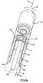
- FIG. 5e is a perspective view showing a piezoelectric sensor 120 provided on supporting structure 122 in a spaced-apart relation to the electrode 110 (as shown in FIG. 5a , but not connected to the shaft 130).
- a piezoelectric sensor 120 may be mounted within the catheter shaft 14 (e.g., within a compliant material).
- the compliant material may act as a mechanical coupler as well as a low pass mechanical filter to mitigate spurious high frequency signal artifacts.
- FIG. 6a -c are cross-sectional views showing still more alternative disclosures for operatively associating at least one piezoelectric sensor 220 with an electrode 210. It is noted that 200-series reference numbers are used in the embodiments shown in FIG. 6a-c to refer to like elements described above with reference to FIG. 2 and 2a . Therefore the description of some elements may not be repeated in the following discussion.
- the piezoelectric sensor 220 is provided near or adjacent the electrode 210, but is not connected directly to the electrode 210. Such an embodiment serves to electrically, as well as thermally, isolate the piezoelectric sensor 220 from the electrode 210, while still enabling the piezoelectric sensor 220 to respond to stress on the electrode 210 during use (e.g., in the direction of arrows 240 and/or 241).
- the piezoelectric sensor 220 is provided directly adjacent an optional insulating material 252, which in turn is in direct contact with the electrode 210.
- the piezoelectric sensor 220 may be provided in a compliant material 226, such as silicone, or airspace.
- Contact of the electrode 210 with the target tissue causes a stress or strain on the piezoelectric sensor 220, which in turn responds to stresses on the electrode 210 (e.g., in the directions illustrated by arrows 240 and/or 241) by generating electrical (voltage or charge) signals. These electrical signals may be viewed by the user, e.g., as output on an electrical monitoring device.
- the piezoelectric sensor 220 is substantially a "question mark" shape.
- the piezoelectric sensor 220 is substantially an arc or half-circle shape.
- the piezoelectric sensor 220 is substantially a spiral shape.
- other shapes for the piezoelectric sensor 220 are also contemplated, as will be readily apparent to those having ordinary skill in the art after becoming familiar with the teachings herein.
- the piezoelectric sensor 220 may be a stand-alone laminated structure (e.g., as shown in FIG. 3a-c ) and/or may be provided on a flexible support structure (e.g., a metal "frame” or silicone).
- the flexible support structure may be shaped substantially the same as the piezoelectric sensors 220 shown in FIG. 6a-c .
- the electrode 210 may be spring-biased using a spring or other suitable elastic material to bias the electrode 210 in a forward position.
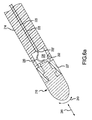
- FIG. 7a -g are perspective views showing still more alternative disclosures for operatively associating at least one piezoelectric sensor 320 with an electrode 310.
- Cross-sectional views are also shown in FIGs. 7b , d , and f so that the arrangement of the piezoelectric sensor(s) can be better seen within the electrode 310.
- 300-series reference numbers are used in the disclosures shown in FIG. 7a-g to refer to like elements described above with reference to FIG. 2 and 2a . Therefore the description of some elements may not be repeated in the following discussion.
- an arcuate piezoelectric sensor 320 is housed in the electrode 310. It is noted that the piezoelectric sensor 320 may be integrally molded within the electrode 310 and/or anchored within the catheter shaft 314.
- cross-sectional view 300a is taken along line 7b-7b in FIG. 7a and shows the arrangement of the piezoelectric sensor 320 in the electrode 310.
- two arcuate piezoelectric sensors 320a, 320b are housed in the electrode 310.
- the piezoelectric sensors 320a, 320b may be mounted substantially perpendicular to one another, as better seen in the FIG.
- FIG. 7d the cross-sectional view 300b being taken along line 7d-7d in FIG. 7c .
- three arcuate piezoelectric sensors 320a, 320b, 320c are housed in the electrode 310.
- the piezoelectric sensors 320a, 320b, 320c can be mounted from 30-180 degrees radial offset, for example sixty degrees, relative to one another, as better seen in the cross-sectional view of FIG. 7f taken along line 7f-7f in FIG. 7e .
- an arcuate piezoelectric sensor 320 is mounted behind the electrode 310 (e.g., similarly to the disclosures described above for FIG. 6a-c ).
- the piezoelectric sensor 320 is not limited to the single arcuate sensor shown in FIG. 7g .
- Other disclosures, such as those shown in FIG. 7c and 7e may also be implemented.
- FIG. 7a-7f where the piezoelectric sensors 320 are housed within the electrode 310) enable manufacturing of relatively small sizes and therefore are particularly suitable for use, e.g., in so-called brush electrodes.
- these disclosures are not limited to any particular size or use.
- other shapes and arrangements of the piezoelectric sensor(s) 320 are also contemplated for the disclosures shown in FIG. 7a-g , as will be readily apparent to those having ordinary skill in the art after becoming familiar with the teachings herein.
- FIG. 8a-h are cross-sectional views showing more alternative disclosures for operatively associating at least one piezoelectric sensor with an electrode, and corresponding cross-sectional views showing exemplary response of the piezoelectric sensor to stress of the electrode. It is noted that 400-series reference numbers are used in the disclosures shown in FIG. 8a-h to refer to like elements described above with reference to FIG. 2 and 2a . Therefore the description of some elements may not be repeated in the following discussion.
- the piezoelectric sensor 420 is operatively associated with the electrode 410 via a translation element 450 positioned between the electrode 410 and the piezoelectric sensor 420.
- the piezoelectric sensor 420 may be electrically and thermally isolated from the electrode 410, such as by using an insulating material 452 between the electrode 410 and the translation element 450 as shown in FIG. 8a-d and 8g-h (but not in FIG. 8e-f ).
- a backing or support element 451 may be provided adjacent the piezoelectric sensor 420 on a side opposite (or "behind") the translation element 450.
- Backing or support element 451 provides mechanical support for the piezoelectric sensor 420 and holds the piezoelectric sensor 420 against the translation element 450, without restricting operation of the piezoelectric sensor 420.
- the backing element 451 provides stress and response modification, such as low pass mechanical filtering, for the piezoelectric sensor 420.
- the translation element 450 may be manufactured of any suitable elastic material, such as, e.g., stainless steel.
- the translation element 450 may also be any suitable shape.
- FIG. 8a-b the translation element 450 is shown as being substantially spherical-shaped.
- FIG. 8c-d the translation element 450 is shown as being substantially square-shaped.
- Other shapes are also contemplated, such as, e.g., elliptical, rectangular, triangular, etc.
- the support element 451 may also be manufactured of any suitable elastic material (e.g., the same stainless steel that the translation element 450 is manufactured from).
- the elastic material allows the elements 450 and 451 to absorb pressure that may be applied head-on to the electrode 410 without damaging the piezoelectric sensor 420.
- the support element 451 may also be any suitable shape, e.g., as discussed above for the translation element 450.
- translation element 450 and support element 451 are not limited to any particular shape or manufacture of any particular material.
- the material these elements 450 and 451 are manufactured from, and the shape of these elements 450 and 451, may be selected based on various design considerations (e.g., desired sensitivity, durability, etc.) to enable the piezoelectric sensor 420 to respond to stress or flexure of the electrode 410.
- the translation element 450 As the translation element 450 moves, it compresses the lower portion and stretches the upper portion of the piezoelectric sensor 420 ("upper” and “lower” referring to the view in FIG. 8a-h ). Of course the compression and stretching is on the order of sub-millimeters and therefore is not actually as pronounced as it is shown in the exaggerated illustration of FIG. 8a-h .
- piezoelectric sensor 420 responds to movement or deflection of the electrode 410 (e.g., in the directions illustrated by arrows 440 and/or 441) by generating electrical (voltage or charge) signals which may be viewed by the user, e.g., as output on an electrical monitoring device.
- Electrical wiring 470 may be connected to the piezoelectric sensor 420 at conductive layer 460. Electrical wiring 471 may also be connected to the piezoelectric sensor 420 at conductive layer 461, or to a ground (e.g., as illustrated by 451 of the supporting structure where the supporting structure 451 is an electrical conductor). It is noted that only one wire needs to be connected to the piezoelectric sensor 420 (and one wire to ground) in this disclosures if the piezoelectric sensor 420 is formed as a single piece.
- the wires may extend through the catheter shaft to deliver electrical signals from the piezoelectric sensor 420 to a data acquisition/processing/output device (not shown), such as, e.g., an echocardiogram (ECG) device.
- a wireless connection may be implemented, e.g., by providing a transmitter in the catheter and a receiver in association with the data acquisition/processing/output device.
- FIG. 9a -f are side and corresponding cross-sectional views showing more alternative disclosures for operatively associating at least one piezoelectric sensor 520 with an electrode 510.
- the cross-sectional views are shown so that the arrangement of the piezoelectric sensor(s) can be better seen within the electrode 510.
- 500-series reference numbers are used in the disclosures shown in FIG. 9a-f to refer to like elements described above with reference to FIG. 2 and 2a . Therefore the description of some elements may not be repeated in the following discussion.
- the piezoelectric sensor 520 is provided on a support structure 522 (e.g., a pole) connected to the electrode 510.
- the piezoelectric sensor 520 may be provided in a compliant material 526, such as silicone or airspace.
- a stress or strain on the piezoelectric sensor 520 which in turn responds to stresses on the electrode 510 (e.g., in the directions illustrated by arrows 540 and/or 541) by generating electrical (voltage or charge) signals.
- electrical signals may be viewed by the user, e.g., as output on an electrical monitoring device.
- the piezoelectric sensor 520 is provided on a support structure that can be thought of as the pole and metal frame of an umbrella, as better seen in FIG. 9b , the cross-sectional view taken along line 9b-9b.
- the piezoelectric sensor 520 is provided on a support structure that can be thought of as a spiral or ring mounted by a cross or T-bar to the pole portion, as better seen in FIG. 9d , the cross-sectional view taken along line 9d-9d.
- the piezoelectric sensor 520 is provided on a support structure that can be thought of as a combination of the umbrella frame in FIG. 9a and the cross or T-bar mounting in FIG.
- FIG. 10a is a cross-sectional view showing another alternative disclosure for operatively associating at least one piezoelectric sensor with an electrode. It is noted that 600-series reference numbers are used in the disclosures shown in FIG. 10a and Figs 10b-j to refer to like elements described above with reference to FIG. 2 and 2a . Therefore the description of some elements may not be repeated in the following discussion.
- the piezoelectric sensor 620 is provided on a half-spherical or "cup” shaped support structure 622 in contact with a substantially spherical or “ball” shaped neck portion 624 of the electrode 610.
- Contact of the electrode 610 with the target tissue causes the neck portion 624 of electrode 610 to move adjacent the "cup" shaped support structure 622, which in turn results in a stress or strain on the piezoelectric sensor 620.
- the piezoelectric sensor responds to these stresses on the electrode 610 by generating electrical (voltage or charge) signals. These electrical signals may be viewed by the user, e.g., as output on an electrical monitoring device.
- the neck portion 624 may be any suitable shape, such as, but not limited to the sphere or "ball” shape shown in FIG. 10a , an elliptical shape, rectangular shape, triangular shape, diamond shape, etc.
- the "cup” shaped support structure 622 may be any suitable shape and does not necessarily have to compliment the neck portion 624.
- the "cup” shaped support structure 622 in FIG. 10a compliments the sphere shaped neck portion 624, but the same "cup” shaped support structure 622 may also be used with a square shaped neck portion 624 (so that it behaves as a cam and engages the support structure 622).
- FIG. 10b is a cross-sectional view of the piezoelectric sensor 620 taken along lines 10b-10Jin FIG. 10a , but for purposes of clarity, showing only the "cup" shaped support structure 622 without the neck portion 624.
- the outer ring is the catheter 614
- ring 690 is backing or support material also seen in FIG. 10a
- the center circle represents the piezoelectric sensor 620.
- the piezoelectric sensor 620 may be segmented. Segmenting the piezoelectric sensor 620 enables both axial and angular (or radial) stresses to be detected during operation.
- FIG. 10c -j are cross-sectional views showing alternative disclosures of the piezoelectric sensor 620 shown in FIG. 10a , wherein the piezoelectric sensor 620 is segmented. Again for purposes of clarity, only the "cup" shaped support structure 622 is shown without the neck portion 624 in FIG. 10c-j .
- the outer ring is the catheter 614
- ring 690 is backing or support material also seen in FIG. 10a
- the center circle represents the piezoelectric sensor 620.
- Segmenting of the piezoelectric sensor 620 is referred to by reference number 692 in FIG. 10c-j . Similar segmentation may be applied on the disclosures of the sensors shown in FIG. 8a-h . Thus the segmentation 462 in FIG. 8a-b may have configurations such as shown in example FIG. 10b-j .
- lumen 695 formed through the piezoelectric sensor 620 may be provided for irrigated electrodes.
Abstract
Description
- The instant invention is directed toward an electrode contact sensing system comprising one or more electro-mechanical sensor, such as a piezoelectric sensor, for assessing catheter contact with a moving surface (e.g., the heart wall) for ablation procedures.
- It is well known that benefits may be gained by forming lesions in tissue if the depth and location of the lesions being formed can be controlled. In particular, it can be desirable to elevate tissue temperature to around 50°C until lesions are formed via coagulation necrosis, which changes the electrical properties of the tissue. For example, lesions may be formed at specific locations in cardiac tissue via coagulation necrosis to lessen or eliminate undesirable atrial fibrillations.
- Several difficulties may be encountered, however, when attempting to form lesions at specific locations using some existing ablation electrodes. One such difficulty encountered with existing ablation electrodes is how to assess tissue contact. Electrode-tissue contact is not readily determined using conventional fluoroscopy techniques. Instead, the physician determines electrode-tissue contact based on his/her experience using the electrode catheter. Such experience only comes with time, and may be quickly lost if the physician does not use the electrode catheter on a regular basis. In addition, when forming lesions in a heart, the beating of the heart further complicates matters, making it difficult to assess and maintain sufficient contact pressure between the electrode and the tissue for a sufficient length of time to form a desired lesion. If the contact between the catheter and the tissue cannot be properly maintained, a quality lesion is unlikely to be formed.
US-A1-2002/0123749 discloses a catheter having an ablation electrode and one or more pressure sensors positioned within a tissue-contacting area of the catheter shaft for providing pressure data indicative of the pressure exerted on the distal portion of the catheter. The pressure sensor(s) may comprise a piezoelectric transducer electrically coupled to a lead that passes through the ablation electrode and the catheter shaft to a microprocessor, which generates an indication of the state of electrode/tissue contact during a catheter procedure.WO95/10978 independent claim 1, whileUS2003130615 discloses an electrode contact sensing system wherein three sensors are arranged on a disc shaped support structure.
It is an object of the present invention to provide an improved electrode contact sensing system.
This object is achieved by the invention ofclaim 1.
Further embodiments of the invention are recited in the dependent claims. - It is desirable to be able to assess electrode contact with a surface (e.g., the heart wall) for tissue ablation procedures. Positioning the electrode against the heart wall creates contact stresses between the electrode and the tissue. This stress may be measured by implementing one or more electro-mechanical sensors, such as a piezoelectric sensor, coupled to the electrode. The piezoelectric sensor(s) generates a voltage signal and charge corresponding to stress of the electrode.
- In an exemplary disclosure, a piezoelectric sensor is operatively associated with an electrode housed within a catheter shaft. In another exemplary disclosure, a plurality of piezoelectric sensors are provided within the electrode catheter. Output from the piezoelectric sensor(s) enables a user (e.g., a physician or technician) to position the electrode catheter against a target tissue with the desired amount of pressure for the ablation procedure.
- An exemplary electrode contact sensing system comprises an electrode housed within a distal portion of a catheter shaft. At least one piezoelectric sensor is operatively associated with the electrode within the catheter shaft. The at least one piezoelectric sensor is responsive to stress of the electrode by generating electrical signals corresponding to the amount of stress. The system also includes an output device electrically connected to the at least one piezoelectric sensor. The output device receives the electrical signals for assessing a level of contact between the electrode and a tissue.
- Electrode-tissue contact for tissue ablation may be assessed by generating piezoelectric signals in response to stress of an electrode housed within a distal portion of a flexible catheter, and assessing a level of contact between the electrode and a moving tissue based on the piezoelectric signals.
- Output may be conveyed to the user in real-time (e.g., at a display device or other interface) so that the user can properly position the electrode on the target tissue with the desired level of contact for the ablation procedure. For example, the user may increase contact pressure if the output indicates insufficient contact. Or for example, the user may reduce contact pressure if the output indicates too much contact.
In a further disclosure, variations of the mechanical load on the sensor are indicative of contact stress between said electrode and the tissue, and the output device is adapted to indicate to the user the contact stress between the electrode and the tissue. Further, the variable electrical signal may have a strength that is proportional to the contact stress. In addition, the variable electrical signal may have an amplitude that is proportional to the magnitude of the contact stress. The variable electrical signal may have a periodicity that, e.g., corresponds to the periodicity of contact stress.
The inventive electrode contacting system may be used to sense electrode-tissue contact by contacting a tissue with the electrode provided at the distal portion of the catheter, generating electric signals in the electro-mechanical sensor in response to contact stress of the electrode with the tissue and outputting the electrical signals to a monitoring device. Preferably, contact stresses between the electrode and tissue are assessed based on the electric signals. Contact may be assessed based on the strength, the amplitude or the periodicity of the electric signals. - The foregoing and other aspects, features, details, utilities, and advantages of the present invention will be apparent from reading the following description and claims, and from reviewing the accompanying drawings.
-
FIG. 1a-b illustrate exemplary contact between an electrode and a moving target tissue. -
FIG. 2 is perspective view of an exemplary electrode with a piezoelectric sensor. -
FIG. 2a is a perspective view of an exemplary supporting structure for mounting a piezoelectric sensor to the electrode as shown inFigure 2 . -
FIG. 3a is a sectional view of an exemplary piezoelectric sensor which may be implemented for use with the electrode. InFIG. 3b-c , the piezoelectric sensor is shown in exaggerated form as it may respond to various stresses. -
FIG. 4 shows exemplary output of an oscilloscope showing a waveform corresponding to electrical signals generated by a piezoelectric sensor. -
FIG. 5a-e are perspective views showing alternative embodiments for operatively associating at least one piezoelectric sensor with an electrode. -
FIG. 6a-c are cross-sectional views showing more alternative embodiments for operatively associating at least one piezoelectric sensor with an electrode, not showing all features of the invention. -
FIG. 7a-g are perspective views and corresponding cross-sectional views showing more alternative embodiments for operatively associating at least one piezoelectric sensor with an electrode, not showing all features of the invention. -
FIG. 8a-h are cross-sectional views showing more alternative embodiments for operatively associating at least one piezoelectric sensor with an electrode, and corresponding cross-sectional views showing exemplary response of the piezoelectric sensor to stress of the electrode, not showing all features of the invention. -
FIG. 9a-f are side and corresponding cross-sectional views showing more alternative embodiment for operatively associating at least one piezoelectric sensor with an electrode, not showing all features of the invention. -
FIG. 10a is a cross-sectional view showing another alternative embodiment for operatively associating at least one piezoelectric sensor with an electrode, not showing all features of the invention.FIG. 10b-j are cross-sectional views showing alternative embodiments of the piezoelectric sensor shown inFIG. 10a , not showing all features of the invention. - Exemplary embodiments of a tissue ablation system of use to assess contact between an electrode in a catheter and a tissue are depicted in the figures. Exemplary systems comprise an electrode which may be inserted into the patient using a catheter, e.g., for forming ablative lesions inside the patient's heart. During an exemplary ablation procedure, a user (e.g., the patient's physician or a technician) may insert the catheter into one of the patient's blood vessels, e.g., through the leg or the patient's neck. The user, guided by a real-time fluoroscopy imaging device, moves the catheter into the patient's heart.
- When the catheter reaches the patient's heart, electrodes at the distal portion of the catheter may be implemented to electrically map the myocardium (i.e., muscular tissue in the heart wall) and locate a target tissue. After locating the target tissue, the user must move the catheter into contact with the target tissue before applying ablative energy from the same or other electrodes in the catheter to form an ablative lesion or lesions. The level of contact is often critical to form sufficiently deep ablative lesions on the target tissue without damaging surrounding tissue in the heart.
- As described further below, the system may include one or more electro-mechanical sensors, such as a piezoelectric sensor, which generate electric signals in response to the electrode coming into contact with a surface (e.g., target tissue within the beating heart). Accordingly, embodiments of the present invention provide a number of advantages, including, for example, the ability to apply a reasonable amount of ablative energy to a target tissue while mitigating tissue contact problems. The invention also facilitates enhanced tissue contact in difficult environments (e.g., during lesion formation on a moving surface inside a beating heart).
-
FIG. 1a and 1b illustrate exemplary contact between anelectrode 10 and a target tissue 12 (e.g., myocardium).Electrode 10 may be provided in aflexible shaft 14 of thecatheter 16. Theflexible catheter shaft 14 may be made of a plastic or other suitable material which enables theelectrode 10 to be readily inserted into the patient's heart through the blood vessels, and to be moved or deflected by movement of an adjacent tissue (e.g., target tissue 12). - The
electrode 10 may be electrically connected via suitable wiring through thecatheter shaft 14 to a generator (not shown), such as, e.g., a radio frequency (RF) generator. Theelectrode 10 is thus operable to emit electrical energy (e.g., RF current) near the tip of theelectrode 10 for forming thermal lesion(s) on the target tissue during ablation procedures. - A user may operate a handle portion (not shown) of the
catheter 16 to manually position theelectrode 10 inside the patient's heart so that theelectrode 10 is in contact with thetarget tissue 12. InFIG. 1a , theelectrode 10 is shown having little, if any, contact with thetarget tissue 12, e.g., theelectrode 10 may be "floating" adjacent thetarget tissue 12 as the user is positioning theelectrode 10 usingcatheter 16 in the heart for an ablation procedure. InFIG. 1b , theelectrode 10 is shown in contact with thetarget tissue 12. - When the
electrode 10 is in sufficient or "good" contact with thetarget tissue 12, theelectrode 10 may be stressed or deflected by contact with thetarget tissue 12 generally in the directions illustrated byarrows 18. Stress or deflection of theelectrode 10 may be measured in real-time using at least onepiezoelectric sensor 20 to assess contact between theelectrode 10 and thetarget tissue 12, as described more fully below. - Before continuing, it is noted that the contact and motion illustrated by
FIG. 1b is shown for purposes of illustration and is not intended to be limiting. Other contact and motion may also exist and/or be desired by the user. The definition of sufficient or "good" contact may depend at least to some extent on various operating conditions, such as, e.g., the type of target tissue, desired depth of the ablation lesion, and power and duration of the applied RF energy, to name only a few examples. - It is also noted that other components typical of systems which are conventionally implemented for tissue ablation are not shown or described herein for purposes of brevity. Such components may nevertheless also be provided as part of, or for use with, the
electrode 10. For example, these systems commonly include or are used in conjunction with an ECG recording system, and/or various controls for performing the ablation procedure. Such components are well understood in the medical devices arts and therefore further explanation is not necessary for a complete understanding of the invention. - As previously mentioned, one or more
piezoelectric sensors 20 may be operatively associated with theelectrode 10 to measure stress of theelectrode 10 when in contact with thetarget tissue 12.FIG. 2 is a perspective view of anexemplary electrode 10 operatively associated with apiezoelectric sensor 20. In this embodiment, thepiezoelectric sensor 20 is provided on a supportingstructure 22 shaped as a tripod.FIG. 2a is a perspective view of an exemplary supportingstructure 22 shaped as a tripod withpiezoelectric sensor 20 provided thereon. Thepiezoelectric sensor 20 may be formed as a singlepiece having arms 20a-c connected by acollar 21 and extending at least partially down eachleg 22a-c of the supportingstructure 22. The supportingstructure 22 is mounted directly to theelectrode 20 onneck portion 24, as shown inFigure 2 . - Optionally, the supporting
structure 22 withpiezoelectric sensor 20 may be provided within an insulated cavity orcompliant section 26 of thecatheter shaft 14. In addition to housing thepiezoelectric sensor 20 in theelectrode 10, and protecting thepiezoelectric sensor 20 from external damage or corrosion, thecompliant section 26 may serve as a low pass mechanical filter. That is, thecompliant section 26 attenuates high frequency "noise" signals caused, e.g., by minor vibrations from intermittent contact during positioning of theelectrode 10 adjacent thetarget tissue 12. Accordingly, high frequency noise signals are damped, or even non-existent, as output for the user. -
Electrical wiring 28 may be connected to the piezoelectric sensor 20 (e.g., as illustrated by connection 28').Electrical wiring 29 may also be connected to a ground (e.g., as illustrated by connection 29' to theleg 22c of the supportingstructure 22 where the supporting structure is an electrical conductor). It is noted that only one wire needs to be connected to the piezoelectric sensor 20 (and one wire to ground) in this disclosure because thepiezoelectric sensor 20 is formed as a single piece. The wires 28-29 may extend through thecatheter shaft 14 to deliver electrical signals from thepiezoelectric sensor 20 to a data acquisition/processing/output device (not shown), such as, e.g., an echocardiogram (ECG) device. Alternatively, a wireless connection may be implemented, e.g., by providing a transmitter in the catheter and a receiver in association with the data acquisition/processing/output device. - In use, the
piezoelectric sensor 20 responds to electrode-tissue contact stresses by generating electrical energy (e.g., a voltage or charge). Accordingly, when theelectrode 10 is positioned in contact with thetarget tissue 12,piezoelectric sensor 20 generates an electrical signal corresponding to stress of theelectrode 10. The resulting electrical signal may be processed and/or otherwise output for the user so that the user is able to determine when theelectrode 10 is positioned with the desired level of contact with thetarget tissue 12. - Piezoelectric sensors which generate electrical energy in response to applied mechanical stress are well-understood in the electro-mechanical arts. In general, piezoelectric sensors comprise a piezoelectric material which contains positive and negative electrical charges. In a neutral or "non-stressed" state, these electrical charges are symmetrically distributed in the piezoelectric material such that the material exhibits an overall neutral electrical charge. However, subjecting the piezoelectric material to a mechanical stress (e.g., flexure, pressure, and/or tension) disturbs the symmetrical distribution of electrical charges, thereby generating electrical energy across the material. Even minor deformation of some piezoelectric materials (e.g., on the order of nanometers) may generate a measurable voltage signal. Operation of piezoelectric material may be better understood with brief reference to
FIG. 3a-c -
FIG. 3a is a cross-sectional perspective view of a portion of an exemplarypiezoelectric sensor 20 which may be implemented for use with theelectrode 10. InFIG. 3b -c, thepiezoelectric sensor 20 is shown in exaggerated form as it may respond to various stresses, whereinFIG. 3b is a side-view of thepiezoelectric sensor 20 shown inFIG. 3a, and FIG. 3c is a top-view of thepiezoelectric sensor 20 shown inFIG. 3a . - In an exemplary disclosure, the
piezoelectric sensor 20 may be a laminated sensor, having a plurality of laminated layers. Although not required, laminating the sensor increases its sensitivity. The laminated layers may comprise apiezoelectric material 30 "sandwiched" betweenmetal layers protective coating piezoelectric material 30, e.g., for delivery as electrical signals via electrical wiring to a data acquisition/processing/output device. Metal layers 32a and 32b serve to collect electrical energy in response to stress of thepiezoelectric material 30. Piezoelectric material, such as PVDF (Kynar), is commercially available as a highly-sensitive, thin, flexible polymer film, which makes it particularly desirable for use with deflectable catheters.Protective coating - It is noted that the laminated layers of
piezoelectric sensor 20 are not limited to any particular material and/or configuration. For example, thepiezoelectric sensor 20 is not limited to use withseparate metal layers piezoelectric sensor 20 limited to the generally rectangular configuration shown inFIG. 3 a. - In an exemplary disclosure, the
piezoelectric material 30 may comprise a thin, flexible, polymer-based material. One such piezoelectric film is a polyvinylidene fluoride (PVDF) film commercially available from the Sensor Products Division of Measurement Specialties, Inc. (Norristown, Pennsylvania). This PVDF film is approximately 28 µm thick, enabling the PVDF film to be readily housed within thecatheter shaft 14. - In addition, this PVDF film has a wide frequency range of about 0.001 Hz to 109 Hz and a high dynamic stress constant (g31 = 216 x 10-3 Vm/N). For purposes of illustration, other common piezoelectric materials, such as lead zirconate titanate (PZT) has a dynamic stress constant (g31) of 10 x 10-3 Vm/N, and barium titanium oxide (BaTiO3) has a dynamic stress constant (g31) of 5 x 10⁻³ Vm/N. Accordingly, the PVDF film is very sensitive, exhibiting a relatively high voltage response to relatively small mechanical stresses, and is therefore well-suited for measuring dynamic stresses and strains.
- Of course the
piezoelectric sensor 20 described above with reference toFIG. 3a is for purposes of illustration and not intended to be limiting. Other piezoelectric sensors may also be implemented, and are not limited to laminated piezoelectric film. Nor are piezoelectric sensors limited to use with any particular type or size of piezoelectric material. Selection ofpiezoelectric sensor 20 for use with theelectrode 10 may be application-specific and depend at least in part on one or more design considerations, such as, but not limited to, the desired sensitivity and/or spatial constraints for housing the piezoelectric sensor. -
Piezoelectric sensor 20 is shown inFIG. 3a in a neutral state. In the neutral state, thepiezoelectric material 30 is not subject to any stresses or strains. Accordingly, the electrical charges are symmetrically distributed on either side of the neutral plane N in thepiezoelectric material 30 such that the material exhibits an overall neutral electrical charge. - The most widely used coefficients, d3n (for charge) and g3n (for voltage), possess two subscripts. The first refers to the electrical axis, while the second subscript refers to the mechanical axis. Because piezoelectric film is thin, the electrodes are only applied to the top and bottom film surfaces. Accordingly, the electrical axis is always referred to as "3", as the charge or voltage is always transferred through the thickness (n = 3) of the film. The mechanical axis can be either 1, 2, or 3, because the stress can be applied to any of these axes. Typically, piezoelectric film is used in the mechanical 1 direction for low frequency sensing and actuation (< 100KHz) and in the mechanical 3 direction for high ultrasound sensing and actuation (> 100KHz). These stresses can be better understood with reference to
FIG. 3b and 3c . -
FIG. 3b is a side-view of thepiezoelectric sensor 20 shown inFIG. 3a . InFIG. 3b , thepiezoelectric sensor 20 is shown in exaggerated form as it may respond to transverse stresses applied generally in the direction ofarrow 36. In this stressed state, thepiezoelectric material 30 undergoes transverse strain relative to its neutral state, as illustrated by arrows A1 and A2. Thepiezoelectric sensor 20 may also respond to bending stresses. In this stressed state, thepiezoelectric material 30 undergoes flexural strain relative to its neutral state, as illustrated by arrows B1 and B2. -
FIG. 3c is a top-view of thepiezoelectric sensor 20 shown inFIG. 3a . InFIG. 3c , thepiezoelectric sensor 20 is shown in exaggerated form as it may respond to stress distribution applied generally in the direction ofarrows 37. In this stressed state, thepiezoelectric material 30 is longitudinally strained relative to its neutral state, as illustrated by arrows C 1 and C2. - In each case, these stresses disturb the symmetrical distribution of electrical charges, and electrical energy is generated across the
piezoelectric material 30. In operation, this electrical energy may be collected bymetal layers catheter shaft 14 to a signal conditioning/data acquisition/processing/output device (not shown). - Returning to the
piezoelectric sensor 20 shown mounted to theelectrode 10 inFigure 2 , it can be readily seen thatpiezoelectric sensor 20 provided on supportingstructure 22 and mounted to theelectrode 10 is stressed or strained due to stress on the electrode 10 (e.g., in the directions illustrated byarrows 40 and/or 41). Thepiezoelectric sensor 20 responds by generating electrical (voltage) signals. These electrical signals may be viewed by the user, e.g., as output on an electrical monitoring device. -
FIG. 4 is exemplary output of anoscilloscope showing waveform 42 corresponding to electrical signals generated by a piezoelectric sensor (e.g.,piezoelectric sensor 20 inFIG. 2 ) when it is coupled to an electrode in contact with a moving tissue, such as the myocardium. During operation, output such aswaveform 42 may be displayed for a user, e.g., as a waveform on an ECG device. - In an exemplary disclosure, the signal strength (e.g., amplitude) from the
piezoelectric sensor 20 is proportional to the amount of stress of theelectrode 10, and therefore can be used to determine if theelectrode 10 is in good contact with a tissue (e.g., the myocardium). If theelectrode 10 is not in contact with the target tissue, there are no peaks in the resulting waveform 42 (or the peaks are intermittent). On the other hand, a strong correlation between the heartbeat and output by the piezoelectric sensor indicates that theelectrode 10 is in good contact with the moving target tissue. - Signal periodicity is also a strong indicator of dynamic contact assessment. For example, if the period between heartbeats corresponds well with the period output by the
piezoelectric sensor 20, theelectrode 10 is moving in response to the heartbeat (and not some other reason). Accordingly, the user may use this feedback to increase or decrease contact of the catheter with the moving heart wall to achieve the desired contact. - Before continuing, it is noted that any suitable analog and/or digital device may be implemented for indicating electrode-tissue contact to a user. In another exemplary disclosure, the electrical signals generated by
piezoelectric sensor 20 may be further characterized using a suitable processing device such as, but not limited to, a desktop or laptop computer. Such processing device may be implemented to receive the voltage or charge signal generated by the piezoelectric sensor and convert it to a corresponding contact condition for theelectrode 10 and output for the user, e.g., at a display device. - It is also noted that the output device is not limited to a display device. For example, the electrode-tissue contact may be output to the user as an audio signal or tactile feedback (e.g., vibrations) on the handle of the catheter. In any event, circuitry for conveying output of the piezoelectric sensor to a user in one form or another may be readily provided by those having ordinary skill in the electronics arts after becoming familiar with the teachings herein.
-
FIG. 5a -e are perspective views showing alternative embodiments for operatively associating at least onepiezoelectric sensor 120 with anelectrode 110. It is noted that 100-series reference numbers are used in the embodiments shown inFIG. 5a-c to refer to like elements described above with reference toFIG. 2 and2a . Therefore the description of some elements may not be repeated in the following discussion. -
FIG. 5a is a perspective view showing apiezoelectric sensor 120 provided on supportingstructure 122 which in turn is coupled to theelectrode 110 with ashaft 130 in a spaced-apart relation relative to theelectrode 110. Such an embodiment serves to provide thermal and electrical isolation of the piezoelectric sensors from the electrode. Furthermore theshaft 130 may be flexible. The flexibility of the coupling shaft may be used as a low pass mechanical filter to mitigate spurious high frequency signal artifacts. - It should also be noted that the
shaft 130 may be solid or hollow. For example, theshaft 130 may be hollow to permit a fluid to flow through the shaft for use with irrigated catheters. Although not shown, a tube or other conduit may be connected to or pass through theshaft 130 and extend through thecatheter shaft 14 to the handle portion (not shown). -
FIG. 5b is a perspective view showing a plurality of separatepiezoelectric sensors 120a-c (althoughonly sensors piezoelectric sensors 120a-c are mounted at least partially down eachleg 122a-c of the supportingstructure 122, but the separatepiezoelectric sensors 120a-c are not electrically connected to one another. The supportingstructure 122 may be mounted onneck portion 124 close to theelectrode 110 as shown inFIG. 5b . Alternatively, the supportingstructure 122 may be coupled to theelectrode 110 with ashaft 130 in a spaced-apart relation such as described above with reference toFIG. 5a . - It is noted that this embodiment requires additional wiring to be provided through the catheter shaft 14 (or use of the wireless connection mentioned above). That is,
electrical wiring 128a-c may be connected to eachpiezoelectric sensor 120a-c (e.g., as illustrated byconnections 128a'-128c'), andelectrical wiring 129 may be connected to a common ground (e.g., as illustrated by connection 129' onleg 122c of the supportingstructure 122 where the supportingstructure 122 is an electrical conductor). - In use, the
piezoelectric sensor 120 responds to mechanical stresses by generating electrical energy (e.g., a voltage or charge). In addition to detecting contact of the electrode with the target tissue, the relative magnitude and direction of the signal obtained from each of the separatepiezoelectric sensors 120a-c may be used to determine the direction and plane of contact of theelectrode 110. The resulting electrical signal may be processed and/or otherwise output for the user so that the user is able to determine when theelectrode 110 is positioned with the desired level of contact with thetarget tissue 12. -
FIG. 5c is a perspective view showing a single-piece piezoelectric sensor 120 witharm portions 120a-c sandwiched between protective layers of the tripod legs. That is,arm portion 120a of thepiezoelectric sensor 120 is sandwiched betweenprotective layers portion 120b of thepiezoelectric sensor 120 is sandwiched betweenprotective layers portion 120c of thepiezoelectric sensor 120 is sandwiched betweenprotective layers piezoelectric sensor 120, thereby increasing the stiffness of the sensing system and augmenting the output signal. - It is noted that the
piezoelectric sensor 120 may be formed as a single piece, as shown inFIG. 5c , or separate piezoelectric sensors may be provided (e.g., as described above with reference toFIG. 5b ). It is also noted that the supportingstructure 122 may be mounted onneck portion 124 close to theelectrode 110, as shown inFIG. 5c , or the supportingstructure 122 may be coupled to theelectrode 110 with ashaft 130 in a spaced-apart relation relative to the electrode 110 (e.g., as described above with reference toFIG. 5a ). -
FIG. 5d is a perspective view showing the supporting structure (indicated by reference 122') sandwiched between two single-piecepiezoelectric sensors 120a' (and 120b' and 120c' for each leg). The signals from the two piezoelectric sensors may be combined to improve the sensitivity of the contact sensing. Additionally, because stress response of piezoelectric materials is anisotropic, the two layers may be oriented differently with respect to each other to either attenuate directional differences in sensitivity or provide directional information of electrode-tissue contact. - It is noted that the
piezoelectric sensors 120a' (and 120b' and 120c' for each leg) may be formed as a single piece, as shown inFIG. 5d , or separate piezoelectric sensors may be provided (e.g., as described above with reference toFIG. 5b ). It is also noted that the supporting structure 122' may be mounted onneck portion 124 close to theelectrode 110, as shown inFIG. 5c , or the supporting structure 122' may be coupled to theelectrode 110 by ashaft 130 in a spaced-apart relation relative to the electrode 110 (e.g., as described above with reference toFIG. 5a ). -
FIG. 5e is a perspective view showing apiezoelectric sensor 120 provided on supportingstructure 122 in a spaced-apart relation to the electrode 110 (as shown inFIG. 5a , but not connected to the shaft 130). Such an embodiment serves to provide thermal and electrical isolation of the piezoelectric sensors from the electrode. Instead, thepiezoelectric sensor 120 may be mounted within the catheter shaft 14 (e.g., within a compliant material). The compliant material may act as a mechanical coupler as well as a low pass mechanical filter to mitigate spurious high frequency signal artifacts. -
FIG. 6a -c are cross-sectional views showing still more alternative disclosures for operatively associating at least onepiezoelectric sensor 220 with anelectrode 210. It is noted that 200-series reference numbers are used in the embodiments shown inFIG. 6a-c to refer to like elements described above with reference toFIG. 2 and2a . Therefore the description of some elements may not be repeated in the following discussion. - In each of these disclosures, the
piezoelectric sensor 220 is provided near or adjacent theelectrode 210, but is not connected directly to theelectrode 210. Such an embodiment serves to electrically, as well as thermally, isolate thepiezoelectric sensor 220 from theelectrode 210, while still enabling thepiezoelectric sensor 220 to respond to stress on theelectrode 210 during use (e.g., in the direction ofarrows 240 and/or 241). - In one example, the
piezoelectric sensor 220 is provided directly adjacent an optional insulatingmaterial 252, which in turn is in direct contact with theelectrode 210. Thepiezoelectric sensor 220 may be provided in acompliant material 226, such as silicone, or airspace. Contact of theelectrode 210 with the target tissue causes a stress or strain on thepiezoelectric sensor 220, which in turn responds to stresses on the electrode 210 (e.g., in the directions illustrated byarrows 240 and/or 241) by generating electrical (voltage or charge) signals. These electrical signals may be viewed by the user, e.g., as output on an electrical monitoring device. - In
FIG. 6a , thepiezoelectric sensor 220 is substantially a "question mark" shape. InFIG. 6b , thepiezoelectric sensor 220 is substantially an arc or half-circle shape. InFIG. 6c , thepiezoelectric sensor 220 is substantially a spiral shape. Of course other shapes for thepiezoelectric sensor 220 are also contemplated, as will be readily apparent to those having ordinary skill in the art after becoming familiar with the teachings herein. It is noted that thepiezoelectric sensor 220 may be a stand-alone laminated structure (e.g., as shown inFIG. 3a-c ) and/or may be provided on a flexible support structure (e.g., a metal "frame" or silicone). - Although not shown in
FIG. 6a-c , the flexible support structure may be shaped substantially the same as thepiezoelectric sensors 220 shown inFIG. 6a-c . Also not shown inFIG. 6a-c , it is noted, however, that theelectrode 210 may be spring-biased using a spring or other suitable elastic material to bias theelectrode 210 in a forward position. -
FIG. 7a -g are perspective views showing still more alternative disclosures for operatively associating at least onepiezoelectric sensor 320 with anelectrode 310. Cross-sectional views are also shown inFIGs. 7b ,d , andf so that the arrangement of the piezoelectric sensor(s) can be better seen within theelectrode 310. It is noted that 300-series reference numbers are used in the disclosures shown inFIG. 7a-g to refer to like elements described above with reference toFIG. 2 and2a . Therefore the description of some elements may not be repeated in the following discussion. - In
FIG. 7a , an arcuatepiezoelectric sensor 320 is housed in theelectrode 310. It is noted that thepiezoelectric sensor 320 may be integrally molded within theelectrode 310 and/or anchored within thecatheter shaft 314. InFIG. 7b ,cross-sectional view 300a is taken alongline 7b-7b inFIG. 7a and shows the arrangement of thepiezoelectric sensor 320 in theelectrode 310. InFIG. 7c , two arcuatepiezoelectric sensors electrode 310. Thepiezoelectric sensors FIG. 7d , thecross-sectional view 300b being taken alongline 7d-7d inFIG. 7c . InFIG. 7e , three arcuatepiezoelectric sensors electrode 310. Thepiezoelectric sensors FIG. 7f taken alongline 7f-7f inFIG. 7e . - In
FIG. 7g , an arcuatepiezoelectric sensor 320 is mounted behind the electrode 310 (e.g., similarly to the disclosures described above forFIG. 6a-c ). Of course thepiezoelectric sensor 320 is not limited to the single arcuate sensor shown inFIG. 7g . Other disclosures, such as those shown inFIG. 7c and7e may also be implemented. - It is noted that the configurations shown in
FIG. 7a-7f (where thepiezoelectric sensors 320 are housed within the electrode 310) enable manufacturing of relatively small sizes and therefore are particularly suitable for use, e.g., in so-called brush electrodes. However, these disclosures are not limited to any particular size or use. It is also noted that other shapes and arrangements of the piezoelectric sensor(s) 320 are also contemplated for the disclosures shown inFIG. 7a-g , as will be readily apparent to those having ordinary skill in the art after becoming familiar with the teachings herein. -
FIG. 8a-h are cross-sectional views showing more alternative disclosures for operatively associating at least one piezoelectric sensor with an electrode, and corresponding cross-sectional views showing exemplary response of the piezoelectric sensor to stress of the electrode. It is noted that 400-series reference numbers are used in the disclosures shown inFIG. 8a-h to refer to like elements described above with reference toFIG. 2 and2a . Therefore the description of some elements may not be repeated in the following discussion. - In
FIG. 8a-f , thepiezoelectric sensor 420 is operatively associated with theelectrode 410 via atranslation element 450 positioned between theelectrode 410 and thepiezoelectric sensor 420. Optionally, thepiezoelectric sensor 420 may be electrically and thermally isolated from theelectrode 410, such as by using an insulatingmaterial 452 between theelectrode 410 and thetranslation element 450 as shown inFIG. 8a-d and8g-h (but not inFIG. 8e-f ). - Also optionally, a backing or
support element 451 may be provided adjacent thepiezoelectric sensor 420 on a side opposite (or "behind") thetranslation element 450. Backing orsupport element 451 provides mechanical support for thepiezoelectric sensor 420 and holds thepiezoelectric sensor 420 against thetranslation element 450, without restricting operation of thepiezoelectric sensor 420. Furthermore, thebacking element 451 provides stress and response modification, such as low pass mechanical filtering, for thepiezoelectric sensor 420. - The
translation element 450 may be manufactured of any suitable elastic material, such as, e.g., stainless steel. Thetranslation element 450 may also be any suitable shape. InFIG. 8a-b , thetranslation element 450 is shown as being substantially spherical-shaped. InFIG. 8c-d , thetranslation element 450 is shown as being substantially square-shaped. Other shapes are also contemplated, such as, e.g., elliptical, rectangular, triangular, etc. - The
support element 451 may also be manufactured of any suitable elastic material (e.g., the same stainless steel that thetranslation element 450 is manufactured from). The elastic material allows theelements electrode 410 without damaging thepiezoelectric sensor 420. Thesupport element 451 may also be any suitable shape, e.g., as discussed above for thetranslation element 450. - It is noted that
translation element 450 andsupport element 451 are not limited to any particular shape or manufacture of any particular material. The material theseelements elements piezoelectric sensor 420 to respond to stress or flexure of theelectrode 410. - Stress of the
electrode 410 due to contact with the tissue is transmitted to thepiezoelectric sensor 420 via thetranslation element 450. This operation may be better understood with reference to theneutral states 400 to 403 and corresponding flexed states 400' to 403' shown respectively inFIG. 8a-h . It can be seen that when theelectrode 410 moves in the direction of arrow 440 (and/or pressure/strain being applied head on toelectrode 410 in the direction of arrows 441), movement of theelectrode 410 causes thetranslation element 450 to move (although very slightly) along the outside edge of thepiezoelectric sensor 420. As thetranslation element 450 moves, it compresses the lower portion and stretches the upper portion of the piezoelectric sensor 420 ("upper" and "lower" referring to the view inFIG. 8a-h ). Of course the compression and stretching is on the order of sub-millimeters and therefore is not actually as pronounced as it is shown in the exaggerated illustration ofFIG. 8a-h . - It is noted that these stresses or strains on
piezoelectric element 420 occur in the G33 plane, as described in more detail above with referenceFIG. 3c . Again, thepiezoelectric sensor 420 responds to movement or deflection of the electrode 410 (e.g., in the directions illustrated byarrows 440 and/or 441) by generating electrical (voltage or charge) signals which may be viewed by the user, e.g., as output on an electrical monitoring device. -
Electrical wiring 470 may be connected to thepiezoelectric sensor 420 atconductive layer 460.Electrical wiring 471 may also be connected to thepiezoelectric sensor 420 atconductive layer 461, or to a ground (e.g., as illustrated by 451 of the supporting structure where the supportingstructure 451 is an electrical conductor). It is noted that only one wire needs to be connected to the piezoelectric sensor 420 (and one wire to ground) in this disclosures if thepiezoelectric sensor 420 is formed as a single piece. The wires may extend through the catheter shaft to deliver electrical signals from thepiezoelectric sensor 420 to a data acquisition/processing/output device (not shown), such as, e.g., an echocardiogram (ECG) device. Alternatively, a wireless connection may be implemented, e.g., by providing a transmitter in the catheter and a receiver in association with the data acquisition/processing/output device. -
FIG. 9a -f are side and corresponding cross-sectional views showing more alternative disclosures for operatively associating at least onepiezoelectric sensor 520 with anelectrode 510. The cross-sectional views are shown so that the arrangement of the piezoelectric sensor(s) can be better seen within theelectrode 510. It is noted that 500-series reference numbers are used in the disclosures shown inFIG. 9a-f to refer to like elements described above with reference toFIG. 2 and2a . Therefore the description of some elements may not be repeated in the following discussion. - In each of these disclosures, the
piezoelectric sensor 520 is provided on a support structure 522 (e.g., a pole) connected to theelectrode 510. Thepiezoelectric sensor 520 may be provided in acompliant material 526, such as silicone or airspace. Contact of theelectrode 510 with the target tissue causes the support structure to move and results in a stress or strain on thepiezoelectric sensor 520, which in turn responds to stresses on the electrode 510 (e.g., in the directions illustrated byarrows 540 and/or 541) by generating electrical (voltage or charge) signals. These electrical signals may be viewed by the user, e.g., as output on an electrical monitoring device. - In
FIG. 9a , thepiezoelectric sensor 520 is provided on a support structure that can be thought of as the pole and metal frame of an umbrella, as better seen inFIG. 9b , the cross-sectional view taken alongline 9b-9b. InFIG. 9c , thepiezoelectric sensor 520 is provided on a support structure that can be thought of as a spiral or ring mounted by a cross or T-bar to the pole portion, as better seen inFIG. 9d , the cross-sectional view taken alongline 9d-9d. InFIG. 9e , thepiezoelectric sensor 520 is provided on a support structure that can be thought of as a combination of the umbrella frame inFIG. 9a and the cross or T-bar mounting inFIG. 9c , as can also be seen inFIG. 9f , the cross-sectional view taken alongline 9f-9f. Of course other shapes and configurations for supporting thepiezoelectric sensor 520 are also contemplated, as will be readily apparent to those having ordinary skill in the art after becoming familiar with the teachings herein. -
FIG. 10a is a cross-sectional view showing another alternative disclosure for operatively associating at least one piezoelectric sensor with an electrode. It is noted that 600-series reference numbers are used in the disclosures shown inFIG. 10a andFigs 10b-j to refer to like elements described above with reference toFIG. 2 and2a . Therefore the description of some elements may not be repeated in the following discussion. - In each of these disclosures, the
piezoelectric sensor 620 is provided on a half-spherical or "cup" shapedsupport structure 622 in contact with a substantially spherical or "ball" shapedneck portion 624 of theelectrode 610. Contact of theelectrode 610 with the target tissue causes theneck portion 624 ofelectrode 610 to move adjacent the "cup" shapedsupport structure 622, which in turn results in a stress or strain on thepiezoelectric sensor 620. The piezoelectric sensor responds to these stresses on theelectrode 610 by generating electrical (voltage or charge) signals. These electrical signals may be viewed by the user, e.g., as output on an electrical monitoring device. - It is noted that the
neck portion 624 may be any suitable shape, such as, but not limited to the sphere or "ball" shape shown inFIG. 10a , an elliptical shape, rectangular shape, triangular shape, diamond shape, etc. Likewise, the "cup" shapedsupport structure 622 may be any suitable shape and does not necessarily have to compliment theneck portion 624. For example, the "cup" shapedsupport structure 622 inFIG. 10a compliments the sphere shapedneck portion 624, but the same "cup" shapedsupport structure 622 may also be used with a square shaped neck portion 624 (so that it behaves as a cam and engages the support structure 622). -
FIG. 10b is a cross-sectional view of thepiezoelectric sensor 620 taken alonglines 10b-10JinFIG. 10a , but for purposes of clarity, showing only the "cup" shapedsupport structure 622 without theneck portion 624. InFIG. 10b , the outer ring is thecatheter 614,ring 690 is backing or support material also seen inFIG. 10a , and the center circle represents thepiezoelectric sensor 620. - Optionally, the
piezoelectric sensor 620 may be segmented. Segmenting thepiezoelectric sensor 620 enables both axial and angular (or radial) stresses to be detected during operation.FIG. 10c -j are cross-sectional views showing alternative disclosures of thepiezoelectric sensor 620 shown inFIG. 10a , wherein thepiezoelectric sensor 620 is segmented. Again for purposes of clarity, only the "cup" shapedsupport structure 622 is shown without theneck portion 624 inFIG. 10c-j . - In
FIG. 10c-j , the outer ring is thecatheter 614,ring 690 is backing or support material also seen inFIG. 10a , and the center circle represents thepiezoelectric sensor 620. Segmenting of thepiezoelectric sensor 620 is referred to byreference number 692 inFIG. 10c-j . Similar segmentation may be applied on the disclosures of the sensors shown inFIG. 8a-h . Thus thesegmentation 462 inFIG. 8a-b may have configurations such as shown in exampleFIG. 10b-j . In addition, inFIG. 10d and10g ,lumen 695 formed through thepiezoelectric sensor 620 may be provided for irrigated electrodes. - Although several embodiments of this invention have been described above with a certain degree of particularity, those skilled in the art could make numerous alterations to the disclosed embodiments without departing from the scope of this invention. References are only used for identification purposes to aid the reader's understanding of the present invention, and do not create limitations as to the position, orientation, or use of the invention. In addition, various combinations of the embodiments shown are also contemplated even if not particularly described. Changes in detail or structure, such as but not limited to combinations of various aspects of the disclosed embodiments, may be made without departing from the scope of the invention as defined in the appended claims.
Claims (9)
- An electrode contact sensing system for providing information indicative of contact between an electrode and tissue, the system comprising:an electrode (10; 110) provided at a distal portion of a catheter shaft (14);multiple electrically isolated piezoelectrical sensors (20; 120) operatively associated with the electrode and (10; 110) each adapted to generate an electrical signal in response to a mechanical load on said sensor (20; 120) resulting from contact between said electrode (10; 110) and the tissue; andan output device electrically connected to said sensors (20; 120), the output device being adapted to receive the electrical signal and to assess a level of contact between the electrode (10; 110) and the tissue
characterized in that said sensors (20; 120) are arranged on a tripod supporting structure with the sensors (20;120) mounted at least partially down each leg of the supporting structure (122). - The system of claim 1, wherein said multiple electro-mechanical sensors (20; 120) are adapted to generate a variable electrical signal that varies in response to variations in said mechanical load.
- The system of claim 1 or 2, wherein the multiple electro-mechanical sensors (20; 120) include a piezoelectric film.
- The system of any one of claims 1-3, wherein the multiple electro-mechanical sensors (120; 520) are laminated on the support structure (122; 122') and the support structure (122;122') is connected directly to the electrode (110).
- The system of any one of claims 1-3, wherein the multiple electro-mechanical sensors (20; 120) are laminated on a support structure (22; 122; 122') and the support structure is provided in a spaced-apart relation from the electrode (10; 110).
- The system of any preceding claim, wherein the multiple electrically-isolated, electro-mechanical sensors (20; 120) are laminated on a single support structure (22; 122; 122') operatively associated with the electrode (10; 110).
- The system of claim 6, wherein the multiple electrically-isolated, electro-mechanical sensors (20; 120) are adapted to provide information concerning the directionality of the electrode-tissue contact.
- The system of any preceding claim, further comprising a means (26) for reducing noise artifacts, preferably for reducing noise effects from intermittent tissue contact.
- The system of any preceding claim, comprising at least two electro-mechanical sensors (20; 120) adapted for determining the direction and plane of tissue contact with the electrode (10; 110) based on relative magnitude and direction of a signal obtained from each of the at least two electro-mechanical sensors operatively associated with the electrode.
Applications Claiming Priority (2)
| Application Number | Priority Date | Filing Date | Title |
|---|---|---|---|
| US73063405P | 2005-10-27 | 2005-10-27 | |
| PCT/US2006/042119 WO2007050960A2 (en) | 2005-10-27 | 2006-10-27 | Systems and methods for electrode contact assessment |
Publications (3)
| Publication Number | Publication Date |
|---|---|
| EP1948057A2 EP1948057A2 (en) | 2008-07-30 |
| EP1948057A4 EP1948057A4 (en) | 2010-09-01 |
| EP1948057B1 true EP1948057B1 (en) | 2012-03-14 |
Family
ID=37968595
Family Applications (1)
| Application Number | Title | Priority Date | Filing Date |
|---|---|---|---|
| EP06836608A Not-in-force EP1948057B1 (en) | 2005-10-27 | 2006-10-27 | Systems for electrode contact assessment |
Country Status (9)
| Country | Link |
|---|---|
| US (2) | US8021361B2 (en) |
| EP (1) | EP1948057B1 (en) |
| JP (1) | JP4926183B2 (en) |
| AT (1) | ATE548985T1 (en) |
| AU (1) | AU2006305967B2 (en) |
| BR (1) | BRPI0618421A2 (en) |
| CA (1) | CA2626833C (en) |
| IL (1) | IL190875A (en) |
| WO (1) | WO2007050960A2 (en) |
Families Citing this family (161)
| Publication number | Priority date | Publication date | Assignee | Title |
|---|---|---|---|---|
| US7819870B2 (en) | 2005-10-13 | 2010-10-26 | St. Jude Medical, Atrial Fibrillation Division, Inc. | Tissue contact and thermal assessment for brush electrodes |
| US8075498B2 (en) | 2005-03-04 | 2011-12-13 | Endosense Sa | Medical apparatus system having optical fiber load sensing capability |
| US8894589B2 (en) | 2005-08-01 | 2014-11-25 | Endosense Sa | Medical apparatus system having optical fiber load sensing capability |
| US8672936B2 (en) * | 2005-10-13 | 2014-03-18 | St. Jude Medical, Atrial Fibrillation Division, Inc. | Systems and methods for assessing tissue contact |
| US8679109B2 (en) * | 2005-10-13 | 2014-03-25 | St. Jude Medical, Atrial Fibrillation Division, Inc. | Dynamic contact assessment for electrode catheters |
| AU2006305967B2 (en) * | 2005-10-27 | 2013-02-07 | St. Jude Medical, Atrial Fibrillation Division, Inc. | Systems and methods for electrode contact assessment |
| US9492226B2 (en) | 2005-12-06 | 2016-11-15 | St. Jude Medical, Atrial Fibrillation Division, Inc. | Graphical user interface for real-time RF lesion depth display |
| US20090177111A1 (en) * | 2006-12-06 | 2009-07-09 | Miller Stephan P | System and method for displaying contact between a catheter and tissue |
| US8449535B2 (en) * | 2005-12-06 | 2013-05-28 | St. Jude Medical, Atrial Fibrillation Division, Inc. | System and method for assessing coupling between an electrode and tissue |
| US8603084B2 (en) | 2005-12-06 | 2013-12-10 | St. Jude Medical, Atrial Fibrillation Division, Inc. | System and method for assessing the formation of a lesion in tissue |
| US8998890B2 (en) | 2005-12-06 | 2015-04-07 | St. Jude Medical, Atrial Fibrillation Division, Inc. | Assessment of electrode coupling for tissue ablation |
| US9254163B2 (en) | 2005-12-06 | 2016-02-09 | St. Jude Medical, Atrial Fibrillation Division, Inc. | Assessment of electrode coupling for tissue ablation |
| US8403925B2 (en) | 2006-12-06 | 2013-03-26 | St. Jude Medical, Atrial Fibrillation Division, Inc. | System and method for assessing lesions in tissue |
| AU2006321918B2 (en) | 2005-12-06 | 2011-08-25 | St. Jude Medical, Atrial Fibrillation Division Inc. | Assessment of electrode coupling for tissue ablation |
| US10362959B2 (en) * | 2005-12-06 | 2019-07-30 | St. Jude Medical, Atrial Fibrillation Division, Inc. | System and method for assessing the proximity of an electrode to tissue in a body |
| US8406866B2 (en) | 2005-12-06 | 2013-03-26 | St. Jude Medical, Atrial Fibrillation Division, Inc. | System and method for assessing coupling between an electrode and tissue |
| US8567265B2 (en) | 2006-06-09 | 2013-10-29 | Endosense, SA | Triaxial fiber optic force sensing catheter |
| US10085798B2 (en) * | 2006-12-29 | 2018-10-02 | St. Jude Medical, Atrial Fibrillation Division, Inc. | Ablation electrode with tactile sensor |
| US8226648B2 (en) | 2007-12-31 | 2012-07-24 | St. Jude Medical, Atrial Fibrillation Division, Inc. | Pressure-sensitive flexible polymer bipolar electrode |
| US8622935B1 (en) | 2007-05-25 | 2014-01-07 | Endosense Sa | Elongated surgical manipulator with body position and distal force sensing |
| US8357152B2 (en) | 2007-10-08 | 2013-01-22 | Biosense Webster (Israel), Ltd. | Catheter with pressure sensing |
| US8535308B2 (en) | 2007-10-08 | 2013-09-17 | Biosense Webster (Israel), Ltd. | High-sensitivity pressure-sensing probe |
| US8211102B2 (en) * | 2007-12-21 | 2012-07-03 | St. Jude Medical, Atrial Fibrillation Division, Inc. | Contact sensing flexible conductive polymer electrode |
| US10660690B2 (en) | 2007-12-28 | 2020-05-26 | St. Jude Medical, Atrial Fibrillation Division, Inc. | System and method for measurement of an impedance using a catheter such as an ablation catheter |
| US8290578B2 (en) | 2007-12-28 | 2012-10-16 | St. Jude Medical, Atrial Fibrillation Division, Inc. | Method and apparatus for complex impedance compensation |
| US9204927B2 (en) | 2009-05-13 | 2015-12-08 | St. Jude Medical, Atrial Fibrillation Division, Inc. | System and method for presenting information representative of lesion formation in tissue during an ablation procedure |
| DE102008024737B3 (en) * | 2008-05-20 | 2010-01-07 | SectorCon Ingenieurgesellschaft für System- und Softwaretechnik mbH | Piezoelectric sensor for pressure fluctuation measurement |
| US8437832B2 (en) | 2008-06-06 | 2013-05-07 | Biosense Webster, Inc. | Catheter with bendable tip |
| US8206385B2 (en) * | 2008-06-09 | 2012-06-26 | St. Jude Medical, Atrial Fibrillation Division, Inc. | Catheter assembly with front-loaded tip and multi-contact connector |
| US9101734B2 (en) * | 2008-09-09 | 2015-08-11 | Biosense Webster, Inc. | Force-sensing catheter with bonded center strut |
| US9326700B2 (en) | 2008-12-23 | 2016-05-03 | Biosense Webster (Israel) Ltd. | Catheter display showing tip angle and pressure |
| US8475450B2 (en) | 2008-12-30 | 2013-07-02 | Biosense Webster, Inc. | Dual-purpose lasso catheter with irrigation |
| US8600472B2 (en) | 2008-12-30 | 2013-12-03 | Biosense Webster (Israel), Ltd. | Dual-purpose lasso catheter with irrigation using circumferentially arranged ring bump electrodes |
| US9307931B2 (en) * | 2008-12-31 | 2016-04-12 | St. Jude Medical, Atrial Fibrillation Division, Inc. | Multiple shell construction to emulate chamber contraction with a mapping system |
| JP5693471B2 (en) | 2009-02-11 | 2015-04-01 | ボストン サイエンティフィック サイムド,インコーポレイテッドBoston Scientific Scimed,Inc. | Insulated ablation catheter device and use thereof |
| CN104605928B (en) | 2009-05-08 | 2018-01-05 | 圣犹达医疗用品国际控股有限公司 | System for controlling lesion size in the ablation based on conduit |
| US9393068B1 (en) | 2009-05-08 | 2016-07-19 | St. Jude Medical International Holding S.À R.L. | Method for predicting the probability of steam pop in RF ablation therapy |
| EP2467689B1 (en) | 2009-08-21 | 2019-12-25 | St. Jude Medical, Cardiology Division, Inc. | Flexible sensors and related systems for determining forces applied to an object, such as a surgical instrument |
| WO2011053766A1 (en) * | 2009-10-30 | 2011-05-05 | Advanced Bionics, Llc | Steerable stylet |
| US10688278B2 (en) | 2009-11-30 | 2020-06-23 | Biosense Webster (Israel), Ltd. | Catheter with pressure measuring tip |
| US10624553B2 (en) | 2009-12-08 | 2020-04-21 | Biosense Webster (Israel), Ltd. | Probe data mapping using contact information |
| US8920415B2 (en) * | 2009-12-16 | 2014-12-30 | Biosense Webster (Israel) Ltd. | Catheter with helical electrode |
| US8521462B2 (en) * | 2009-12-23 | 2013-08-27 | Biosense Webster (Israel), Ltd. | Calibration system for a pressure-sensitive catheter |
| US8374819B2 (en) | 2009-12-23 | 2013-02-12 | Biosense Webster (Israel), Ltd. | Actuator-based calibration system for a pressure-sensitive catheter |
| US9962217B2 (en) | 2009-12-23 | 2018-05-08 | Biosense Webster (Israel) Ltd. | Estimation and mapping of ablation volume |
| US8926604B2 (en) * | 2009-12-23 | 2015-01-06 | Biosense Webster (Israel) Ltd. | Estimation and mapping of ablation volume |
| AU2015202549B2 (en) * | 2009-12-28 | 2017-03-02 | Biosense Webster (Israel), Ltd. | Catheter with strain gauge sensor |
| US8529476B2 (en) * | 2009-12-28 | 2013-09-10 | Biosense Webster (Israel), Ltd. | Catheter with strain gauge sensor |
| US8608735B2 (en) | 2009-12-30 | 2013-12-17 | Biosense Webster (Israel) Ltd. | Catheter with arcuate end section |
| US9358072B2 (en) * | 2010-01-15 | 2016-06-07 | Immersion Corporation | Systems and methods for minimally invasive surgical tools with haptic feedback |
| US8374670B2 (en) | 2010-01-22 | 2013-02-12 | Biosense Webster, Inc. | Catheter having a force sensing distal tip |
| US8798952B2 (en) | 2010-06-10 | 2014-08-05 | Biosense Webster (Israel) Ltd. | Weight-based calibration system for a pressure sensitive catheter |
| US8226580B2 (en) | 2010-06-30 | 2012-07-24 | Biosense Webster (Israel), Ltd. | Pressure sensing for a multi-arm catheter |
| US8380276B2 (en) * | 2010-08-16 | 2013-02-19 | Biosense Webster, Inc. | Catheter with thin film pressure sensing distal tip |
| US8731859B2 (en) | 2010-10-07 | 2014-05-20 | Biosense Webster (Israel) Ltd. | Calibration system for a force-sensing catheter |
| US8979772B2 (en) | 2010-11-03 | 2015-03-17 | Biosense Webster (Israel), Ltd. | Zero-drift detection and correction in contact force measurements |
| US8532738B2 (en) | 2010-11-04 | 2013-09-10 | Biosense Webster (Israel), Ltd. | Visualization of catheter-tissue contact by map distortion |
| EP2640280B1 (en) * | 2010-11-16 | 2022-03-16 | TVA Medical, Inc. | Devices for forming a fistula |
| US9211094B2 (en) | 2010-12-10 | 2015-12-15 | Biosense Webster (Israel), Ltd. | System and method for detection of metal disturbance based on contact force measurement |
| US9044244B2 (en) | 2010-12-10 | 2015-06-02 | Biosense Webster (Israel), Ltd. | System and method for detection of metal disturbance based on mutual inductance measurement |
| US10307205B2 (en) | 2010-12-10 | 2019-06-04 | Biosense Webster (Israel) Ltd. | System and method for detection of metal disturbance based on orthogonal field components |
| CN103429183B (en) | 2010-12-27 | 2016-01-06 | 圣犹达医疗用品卢森堡控股有限公司 | Heavily prognoses system is joined based on the atrial walls electricity recording contact force in radiofrequency ablation procedures |
| US9149327B2 (en) | 2010-12-27 | 2015-10-06 | St. Jude Medical Luxembourg Holding S.À.R.L. | Prediction of atrial wall electrical reconnection based on contact force measured during RF ablation |
| US9002442B2 (en) | 2011-01-13 | 2015-04-07 | Rhythmia Medical, Inc. | Beat alignment and selection for cardiac mapping |
| US9277872B2 (en) | 2011-01-13 | 2016-03-08 | Rhythmia Medical, Inc. | Electroanatomical mapping |
| US8333103B2 (en) | 2011-03-30 | 2012-12-18 | Biosense Webster (Israel), Ltd. | Calibration of a force measuring system for large bend angles of a catheter |
| WO2012142588A1 (en) | 2011-04-14 | 2012-10-18 | Endosense S.A. | Compact force sensor for catheters |
| US9220433B2 (en) | 2011-06-30 | 2015-12-29 | Biosense Webster (Israel), Ltd. | Catheter with variable arcuate distal section |
| US9662169B2 (en) | 2011-07-30 | 2017-05-30 | Biosense Webster (Israel) Ltd. | Catheter with flow balancing valve |
| US9603659B2 (en) | 2011-09-14 | 2017-03-28 | Boston Scientific Scimed Inc. | Ablation device with ionically conductive balloon |
| US10791950B2 (en) | 2011-09-30 | 2020-10-06 | Biosense Webster (Israel) Ltd. | In-vivo calibration of contact force-sensing catheters using auto zero zones |
| SG11201402610QA (en) | 2011-12-09 | 2014-10-30 | Metavention Inc | Therapeutic neuromodulation of the hepatic system |
| US9039700B2 (en) * | 2011-12-29 | 2015-05-26 | St. Jude Medical, Atrial Fibrillation Division, Inc. | Irrigated ablation catheter with contact force sensing mechanism |
| EP2797539B1 (en) | 2011-12-29 | 2020-12-02 | St. Jude Medical Atrial Fibrillation Division Inc. | System for optimized coupling of ablation catheters to body tissues and evaluation of lesions formed by the catheters |
| US8945025B2 (en) | 2011-12-30 | 2015-02-03 | St. Jude Medical, Atrial Fibrillation Division, Inc. | Catheter with atraumatic tip |
| US9687289B2 (en) | 2012-01-04 | 2017-06-27 | Biosense Webster (Israel) Ltd. | Contact assessment based on phase measurement |
| AU2013207994B2 (en) | 2012-01-10 | 2015-05-07 | Boston Scientific Scimed, Inc. | Electrophysiology system |
| US8945113B2 (en) * | 2012-04-05 | 2015-02-03 | Covidien Lp | Electrosurgical tissue ablation systems capable of detecting excessive bending of a probe and alerting a user |
| WO2013165584A1 (en) | 2012-05-04 | 2013-11-07 | St. Jude Medical, Atrial Fibrillation Division, Inc. | System and method for controlling delivery of ablation energy to tissue |
| US9226710B2 (en) | 2012-06-25 | 2016-01-05 | Biosense Webster (Israel) Ltd. | Wireless catheter with base wireless transceiver |
| US9168004B2 (en) | 2012-08-20 | 2015-10-27 | Biosense Webster (Israel) Ltd. | Machine learning in determining catheter electrode contact |
| US11096741B2 (en) | 2012-10-10 | 2021-08-24 | Biosense Webster (Israel) Ltd. | Ablation power control based on contact force |
| US9486276B2 (en) | 2012-10-11 | 2016-11-08 | Tva Medical, Inc. | Devices and methods for fistula formation |
| US20140142438A1 (en) | 2012-11-19 | 2014-05-22 | Biosense Webster (Israel), Ltd. | Using location and force measurements to estimate tissue thickness |
| US9427167B2 (en) | 2012-12-20 | 2016-08-30 | Boston Scientific Scimed, Inc. | Real-time feedback for electrode contact during mapping |
| US9204841B2 (en) | 2012-12-31 | 2015-12-08 | Biosense Webster (Israel) Ltd. | Catheter with serially connected sensing structures and methods of calibration and detection |
| US9204820B2 (en) | 2012-12-31 | 2015-12-08 | Biosense Webster (Israel) Ltd. | Catheter with combined position and pressure sensing structures |
| US9295430B2 (en) * | 2013-02-07 | 2016-03-29 | Biosense Webster (Israel), Ltd. | Operator controlled mixed modality feedback |
| US9179971B2 (en) * | 2013-02-11 | 2015-11-10 | St. Jude Medical, Atrial Fibrillation Division, Inc. | Printed electrode catheter |
| US9486272B2 (en) | 2013-03-12 | 2016-11-08 | Biosense Webster (Israel) Ltd. | Force feedback device and method for catheters |
| AU2014236149A1 (en) | 2013-03-14 | 2015-09-17 | Tva Medical, Inc. | Fistula formation devices and methods therefor |
| EP3007613B1 (en) | 2013-06-11 | 2018-05-30 | St. Jude Medical Atrial Fibrillation Division Inc. | Multi-electrode impedance sensing |
| US9949664B2 (en) | 2013-08-27 | 2018-04-24 | Biosense Webster (Israel) Ltd. | Determining non-contact state for a catheter |
| US9974608B2 (en) | 2013-08-27 | 2018-05-22 | Biosense Webster (Israel) Ltd. | Determining absence of contact for a catheter |
| US10682175B2 (en) | 2013-11-06 | 2020-06-16 | Biosense Webster (Israel) Ltd. | Using catheter position and temperature measurement to detect movement from ablation point |
| US9314191B2 (en) | 2013-11-19 | 2016-04-19 | Pacesetter, Inc. | Method and system to measure cardiac motion using a cardiovascular navigation system |
| US9814406B2 (en) | 2013-11-19 | 2017-11-14 | Pacesetter, Inc. | Method and system to identify motion data associated with consistent electrical and mechanical behavior for a region of interest |
| US9301713B2 (en) | 2013-11-19 | 2016-04-05 | Pacesetter, Inc. | Method and system to assess mechanical dyssynchrony based on motion data collected by a navigation system |
| WO2015138998A1 (en) | 2014-03-14 | 2015-09-17 | Tva Medical, Inc. | Fistula formation devices and methods therefor |
| US9380940B2 (en) | 2014-05-05 | 2016-07-05 | Pacesetter, Inc. | Method and system for displaying a three dimensional visualization of cardiac motion |
| US9763591B2 (en) | 2014-05-05 | 2017-09-19 | Pacesetter, Inc. | Method and system to subdivide a mapping area for mechanical activation analysis |
| US10285647B2 (en) | 2014-05-05 | 2019-05-14 | Pacesetter Inc. | Method and system to automatically assign map points to anatomical segments and determine mechanical activation time |
| US9861823B2 (en) | 2014-05-05 | 2018-01-09 | Pacesetter, Inc. | Cardiac resynchronization system and method |
| US9700233B2 (en) | 2014-05-05 | 2017-07-11 | Pacesetter, Inc. | Method and system to equalizing cardiac cycle length between map points |
| US9364170B2 (en) | 2014-05-05 | 2016-06-14 | Pacesetter, Inc. | Method and system to characterize motion data based on neighboring map points |
| US9302099B2 (en) | 2014-05-05 | 2016-04-05 | Pacesetter, Inc. | System and method for evaluating lead stability of an implantable medical device |
| US9895076B2 (en) | 2014-05-05 | 2018-02-20 | Pacesetter, Inc. | Method and system to determine cardiac cycle length in connection with cardiac mapping |
| US10105077B2 (en) | 2014-05-05 | 2018-10-23 | Pacesetter, Inc. | Method and system for calculating strain from characterization data of a cardiac chamber |
| US10327744B2 (en) | 2014-06-26 | 2019-06-25 | Biosense Webster (Israel) Ltd | Assistive manual zeroing visualization |
| US10646666B2 (en) | 2014-08-27 | 2020-05-12 | Tva Medical, Inc. | Cryolipolysis devices and methods therefor |
| US10524684B2 (en) | 2014-10-13 | 2020-01-07 | Boston Scientific Scimed Inc | Tissue diagnosis and treatment using mini-electrodes |
| US10603105B2 (en) | 2014-10-24 | 2020-03-31 | Boston Scientific Scimed Inc | Medical devices with a flexible electrode assembly coupled to an ablation tip |
| US9743854B2 (en) | 2014-12-18 | 2017-08-29 | Boston Scientific Scimed, Inc. | Real-time morphology analysis for lesion assessment |
| US10327734B2 (en) | 2014-12-30 | 2019-06-25 | Biosense Webster (Israel) Ltd. | Measurement of tissue thickness using ultrasound and force measurements |
| US10603040B1 (en) | 2015-02-09 | 2020-03-31 | Tva Medical, Inc. | Methods for treating hypertension and reducing blood pressure with formation of fistula |
| CN104825234A (en) * | 2015-05-15 | 2015-08-12 | 四川锦江电子科技有限公司 | Detecting method and device for attaching of multi-electrode ablation catheter to heart tissue |
| US10682176B2 (en) * | 2015-08-25 | 2020-06-16 | Biosense Webster (Israel) Ltd. | System and method for controlling catheter power based on contact force |
| US10327859B2 (en) | 2015-09-21 | 2019-06-25 | Biosense Webster (Israel) Ltd. | Catheter stability indication |
| CN108024747B (en) | 2015-09-26 | 2020-12-04 | 波士顿科学医学有限公司 | Intracardiac EGM signal for beat matching and acceptance |
| US10383543B2 (en) | 2015-11-11 | 2019-08-20 | Biosense Webster (Israel) Ltd. | Symmetric short contact force sensor with four coils |
| EP3376986B1 (en) | 2016-01-07 | 2020-02-19 | St. Jude Medical International Holding S.à r.l. | Medical device with multi-core fiber for optical sensing |
| WO2017124062A1 (en) | 2016-01-15 | 2017-07-20 | Tva Medical, Inc. | Devices and methods for forming a fistula |
| EP3402561B1 (en) | 2016-01-15 | 2024-02-28 | TVA Medical, Inc. | Devices for advancing a wire |
| US10874422B2 (en) | 2016-01-15 | 2020-12-29 | Tva Medical, Inc. | Systems and methods for increasing blood flow |
| US10350423B2 (en) | 2016-02-04 | 2019-07-16 | Cardiac Pacemakers, Inc. | Delivery system with force sensor for leadless cardiac device |
| US10524859B2 (en) | 2016-06-07 | 2020-01-07 | Metavention, Inc. | Therapeutic tissue modulation devices and methods |
| US10245064B2 (en) * | 2016-07-12 | 2019-04-02 | Ethicon Llc | Ultrasonic surgical instrument with piezoelectric central lumen transducer |
| JP7194676B2 (en) | 2016-09-25 | 2022-12-22 | ティーブイエー メディカル, インコーポレイテッド | Vascular stent device and method |
| CA3039534A1 (en) * | 2016-10-11 | 2018-04-19 | Acutus Medical, Inc. | Ablation system with force control |
| US11000201B2 (en) | 2016-11-09 | 2021-05-11 | Biosense Webster (Israel) Ltd. | Coils formed in folded nitinol sheet |
| EP3821794B1 (en) * | 2016-12-16 | 2023-02-15 | St. Jude Medical International Holding S.à r.l. | Wireless force sensor |
| US11317965B2 (en) | 2017-03-08 | 2022-05-03 | Biosense Webster (Israel) Ltd. | Reduced size force sensor |
| US10660574B2 (en) | 2017-03-08 | 2020-05-26 | Biosense Webster (Israel) Ltd. | Low cost planar spring for force sensor |
| US10219716B2 (en) * | 2017-06-01 | 2019-03-05 | Biosense Webster (Israel) Ltd. | Using a piecewise-linear model of a catheter arm to identify contact with tissue |
| WO2019083999A1 (en) | 2017-10-24 | 2019-05-02 | St. Jude Medical, Cardiology Division, Inc. | System for measuring impedance between a plurality of electrodes of a medical device |
| WO2019126260A1 (en) | 2017-12-19 | 2019-06-27 | St. Jude Medical, Cardiology Division, Inc. | Methods of assessing contact between an electrode and tissue using complex impedance measurements |
| JPWO2019181612A1 (en) * | 2018-03-20 | 2021-03-25 | テルモ株式会社 | Medical device |
| US10686715B2 (en) | 2018-05-09 | 2020-06-16 | Biosig Technologies, Inc. | Apparatus and methods for removing a large-signal voltage offset from a biomedical signal |
| US11000689B2 (en) | 2018-07-15 | 2021-05-11 | Eagle Point Medical LLC | Leadless multi-electrode cardiac pacemakers and methods of implantation thereof |
| US10729902B1 (en) | 2018-07-15 | 2020-08-04 | Eagle Point Medical LLC | Intraseptal multi-electrode cardiac pacemaker and methods of use thereof |
| US10406370B1 (en) | 2018-07-15 | 2019-09-10 | Eagle Point Medical LLC | Single conduit multi-electrode cardiac pacemaker and methods of using thereof |
| US10695558B2 (en) | 2018-07-15 | 2020-06-30 | Eagle Point Medical LLC | Single conduit multi-electrode cardiac pacemaker and methods of using thereof |
| US11497566B2 (en) | 2018-10-26 | 2022-11-15 | Biosense Webster (Israel) Ltd. | Loose mode for robot |
| US20200197097A1 (en) | 2018-12-20 | 2020-06-25 | Biosense Webster (Israel) Ltd. | Catheter representation using a dynamic spring model |
| US11107213B2 (en) | 2018-12-28 | 2021-08-31 | Biosense Webster (Israel) Ltd. | Correcting medical scans |
| WO2020150336A1 (en) | 2019-01-15 | 2020-07-23 | Apn Health, Llc | Cardiac catheter contact force determination |
| US11426126B2 (en) | 2019-05-23 | 2022-08-30 | Biosense Webster (Israel) Ltd. | Indicating electrode contact |
| US20210077180A1 (en) | 2019-09-12 | 2021-03-18 | Biosense Webster (Israel) Ltd. | Balloon Catheter with Force Sensor |
| US11872026B2 (en) | 2019-12-04 | 2024-01-16 | Biosense Webster (Israel) Ltd. | Catheter contact force sensor |
| US20220183748A1 (en) | 2020-12-16 | 2022-06-16 | Biosense Webster (Israel) Ltd. | Accurate tissue proximity |
| US11864844B2 (en) | 2020-12-22 | 2024-01-09 | Biosense Webster (Israel) Ltd. | Distal end assembly guidance |
| US20220370145A1 (en) | 2021-05-24 | 2022-11-24 | Biosense Webster (Israel) Ltd. | Gesture based selection of portion of catheter |
| US20220387099A1 (en) | 2021-06-07 | 2022-12-08 | Biosense Webster (Israel) Ltd. | Automatic anatomical feature identification and map segmentation |
| US20220395214A1 (en) | 2021-06-09 | 2022-12-15 | Biosense Webster (Israel) Ltd. | Wave propagation control enhancement |
| US20220395321A1 (en) | 2021-06-10 | 2022-12-15 | Biosense Webster (Israel) Ltd. | Follow wave propagation |
| US20230008606A1 (en) | 2021-07-06 | 2023-01-12 | Biosense Webster (Israel) Ltd. | Contact assessment for balloon catheter |
| US20230028867A1 (en) | 2021-07-23 | 2023-01-26 | Biosense Webster (Israel) Ltd. | Accurate tissue proximity |
| US20230157569A1 (en) | 2021-11-22 | 2023-05-25 | Biosense Webster (Israel) Ltd. | Mapping System with Real Time Electrogram Overlay |
| US20230210437A1 (en) | 2021-12-30 | 2023-07-06 | Biosense Webster (Israel) Ltd. | Intuitive Mapping System |
| US20230390018A1 (en) * | 2022-06-02 | 2023-12-07 | Boston Scientific Scimed, Inc. | Force sensitive mechanism for contact detection in catheter systems |
| WO2024015808A2 (en) * | 2022-07-11 | 2024-01-18 | The Children's Medical Center Corporation | Anisotropic material tester |
Family Cites Families (70)
| Publication number | Priority date | Publication date | Assignee | Title |
|---|---|---|---|---|
| US491174A (en) * | 1892-10-14 | 1893-02-07 | Coupling-gage | |
| US4682596A (en) * | 1984-05-22 | 1987-07-28 | Cordis Corporation | Electrosurgical catheter and method for vascular applications |
| US4600017A (en) * | 1984-07-19 | 1986-07-15 | Cordis Corporation | Pacing lead with sensor |
| US4991588A (en) * | 1986-07-21 | 1991-02-12 | Pfizer Hospital Products Group, Inc. | Doppler guide wire |
| US4799495A (en) * | 1987-03-20 | 1989-01-24 | National Standard Company | Localization needle assembly |
| US4911174A (en) * | 1989-02-13 | 1990-03-27 | Cardiac Pacemakers, Inc. | Method for matching the sense length of an impedance measuring catheter to a ventricular chamber |
| US4976711A (en) * | 1989-04-13 | 1990-12-11 | Everest Medical Corporation | Ablation catheter with selectively deployable electrodes |
| US5006119A (en) * | 1989-05-25 | 1991-04-09 | Engineering & Research Associates, Inc. | Hollow core coaxial catheter |
| US5028394A (en) * | 1990-04-13 | 1991-07-02 | Bend Research, Inc. | Chemical sensors |
| US5327905A (en) * | 1992-02-14 | 1994-07-12 | Boaz Avitall | Biplanar deflectable catheter for arrhythmogenic tissue ablation |
| US5341807A (en) * | 1992-06-30 | 1994-08-30 | American Cardiac Ablation Co., Inc. | Ablation catheter positioning system |
| DE4235506A1 (en) * | 1992-10-21 | 1994-04-28 | Bavaria Med Tech | Drug injection catheter |
| US5545161A (en) * | 1992-12-01 | 1996-08-13 | Cardiac Pathways Corporation | Catheter for RF ablation having cooled electrode with electrically insulated sleeve |
| US5405346A (en) * | 1993-05-14 | 1995-04-11 | Fidus Medical Technology Corporation | Tunable microwave ablation catheter |
| US5396887A (en) * | 1993-09-23 | 1995-03-14 | Cardiac Pathways Corporation | Apparatus and method for detecting contact pressure |
| WO1995010978A1 (en) * | 1993-10-19 | 1995-04-27 | Ep Technologies, Inc. | Segmented electrode assemblies for ablation of tissue |
| CN1150855C (en) | 1993-10-22 | 2004-05-26 | 吉奈技术私人有限公司 | Transvaginal tube as an aid to laparoscopic surgery |
| US5462521A (en) * | 1993-12-21 | 1995-10-31 | Angeion Corporation | Fluid cooled and perfused tip for a catheter |
| US5447529A (en) | 1994-01-28 | 1995-09-05 | Philadelphia Heart Institute | Method of using endocardial impedance for determining electrode-tissue contact, appropriate sites for arrhythmia ablation and tissue heating during ablation |
| US5447539A (en) * | 1994-02-10 | 1995-09-05 | Dke Incorporated | Method of dyeing polypropylene fiber with more than one color |
| US5536245A (en) * | 1994-11-23 | 1996-07-16 | Dahlbeck; Scott | Laryngoscope pressure sensor and alarm |
| US6246898B1 (en) | 1995-03-28 | 2001-06-12 | Sonometrics Corporation | Method for carrying out a medical procedure using a three-dimensional tracking and imaging system |
| US5895355A (en) * | 1995-05-23 | 1999-04-20 | Cardima, Inc. | Over-the-wire EP catheter |
| US6113592A (en) | 1995-06-09 | 2000-09-05 | Engineering & Research Associates, Inc. | Apparatus and method for controlling ablation depth |
| US6322558B1 (en) * | 1995-06-09 | 2001-11-27 | Engineering & Research Associates, Inc. | Apparatus and method for predicting ablation depth |
| US5697925A (en) * | 1995-06-09 | 1997-12-16 | Engineering & Research Associates, Inc. | Apparatus and method for thermal ablation |
| US5868737A (en) * | 1995-06-09 | 1999-02-09 | Engineering Research & Associates, Inc. | Apparatus and method for determining ablation |
| US5808737A (en) * | 1996-02-29 | 1998-09-15 | Sienna Biotech, Inc. | Pre-analysis chamber for a flow particle analyzer |
| US6066139A (en) | 1996-05-14 | 2000-05-23 | Sherwood Services Ag | Apparatus and method for sterilization and embolization |
| US5893848A (en) | 1996-10-24 | 1999-04-13 | Plc Medical Systems, Inc. | Gauging system for monitoring channel depth in percutaneous endocardial revascularization |
| US5782828A (en) * | 1996-12-11 | 1998-07-21 | Irvine Biomedical, Inc. | Ablation catheter with multiple flexible curves |
| EP1491139B1 (en) | 1997-01-03 | 2007-08-29 | Biosense Webster, Inc. | Bend-responsive catheter |
| GB9703608D0 (en) * | 1997-02-21 | 1997-04-09 | Downhole Products Plc | Casing centraliser |
| US6127672A (en) * | 1997-05-23 | 2000-10-03 | Canadian Space Agency | Topological and motion measuring tool |
| CA2285342C (en) * | 1997-04-01 | 2007-06-19 | Axel Muntermann | Method and device for detecting catheter-tissue contact and interaction with tissue during catheter ablation |
| AU6880598A (en) * | 1997-04-04 | 1998-10-30 | Minnesota Mining And Manufacturing Company | Method and apparatus for controlling contact of biomedical electrodes with patient skin |
| GB9708268D0 (en) * | 1997-04-24 | 1997-06-18 | Gyrus Medical Ltd | An electrosurgical instrument |
| US5836990A (en) * | 1997-09-19 | 1998-11-17 | Medtronic, Inc. | Method and apparatus for determining electrode/tissue contact |
| US6078830A (en) * | 1997-10-01 | 2000-06-20 | Ep Technologies, Inc. | Molded catheter distal end assembly and process for the manufacture thereof |
| US5947905A (en) * | 1997-10-15 | 1999-09-07 | Advanced Coronary Intervention, Inc. | Ultrasound transducer array probe for intraluminal imaging catheter |
| US6845264B1 (en) | 1998-10-08 | 2005-01-18 | Victor Skladnev | Apparatus for recognizing tissue types |
| US6210406B1 (en) * | 1998-12-03 | 2001-04-03 | Cordis Webster, Inc. | Split tip electrode catheter and signal processing RF ablation system |
| US6423057B1 (en) * | 1999-01-25 | 2002-07-23 | The Arizona Board Of Regents On Behalf Of The University Of Arizona | Method and apparatus for monitoring and controlling tissue temperature and lesion formation in radio-frequency ablation procedures |
| US6113593A (en) * | 1999-02-01 | 2000-09-05 | Tu; Lily Chen | Ablation apparatus having temperature and force sensing capabilities |
| US6696844B2 (en) | 1999-06-04 | 2004-02-24 | Engineering & Research Associates, Inc. | Apparatus and method for real time determination of materials' electrical properties |
| US6391024B1 (en) * | 1999-06-17 | 2002-05-21 | Cardiac Pacemakers, Inc. | RF ablation apparatus and method having electrode/tissue contact assessment scheme and electrocardiogram filtering |
| SE514744C2 (en) * | 1999-07-06 | 2001-04-09 | Samba Sensors Ab | Method and apparatus for optical measurement systems |
| US6264653B1 (en) | 1999-09-24 | 2001-07-24 | C. R. Band, Inc. | System and method for gauging the amount of electrode-tissue contact using pulsed radio frequency energy |
| US6629341B2 (en) * | 1999-10-29 | 2003-10-07 | The United States Of America As Represented By The Administrator Of The National Aeronautics And Space Administration | Method of fabricating a piezoelectric composite apparatus |
| WO2001070117A2 (en) * | 2000-03-23 | 2001-09-27 | Microheart, Inc. | Pressure sensor for therapeutic delivery device and method |
| US6837886B2 (en) * | 2000-05-03 | 2005-01-04 | C.R. Bard, Inc. | Apparatus and methods for mapping and ablation in electrophysiology procedures |
| US7011410B2 (en) * | 2000-11-22 | 2006-03-14 | Eyetect, L.L.C. | Method and apparatus for monitoring eye tremor |
| JP4655175B2 (en) * | 2000-12-19 | 2011-03-23 | ソニー株式会社 | MANIPULATOR SYSTEM, MASTER MANIPULATOR, SLAVE MANIPULATOR, CONTROL METHOD THEREOF, AND RECORDING MEDIUM |
| US6666862B2 (en) * | 2001-03-01 | 2003-12-23 | Cardiac Pacemakers, Inc. | Radio frequency ablation system and method linking energy delivery with fluid flow |
| US6800986B2 (en) * | 2002-01-23 | 2004-10-05 | Tdk Corporation | Piezoelectric sensor |
| US6882885B2 (en) | 2002-03-19 | 2005-04-19 | Solarant Medical, Inc. | Heating method for tissue contraction |
| US6709432B2 (en) | 2002-04-26 | 2004-03-23 | Medtronic, Inc. | Ablation methods and medical apparatus using same |
| US9149322B2 (en) * | 2003-03-31 | 2015-10-06 | Edward Wells Knowlton | Method for treatment of tissue |
| US6964661B2 (en) * | 2003-04-02 | 2005-11-15 | Boston Scientific Scimed, Inc. | Endovenous ablation mechanism with feedback control |
| US7105988B2 (en) * | 2003-04-30 | 2006-09-12 | Vibration-X Di Bianchini Emanulee E C. Sas | Piezoelectric device and method to manufacture a piezoelectric device |
| CA2524163C (en) * | 2003-05-02 | 2012-01-03 | Boston Scientific Limited | Multi-functional medical catheter |
| WO2005039835A1 (en) | 2003-10-24 | 2005-05-06 | The University Of Western Ontario | Force reflective robotic control system and minimally invasive surgical device |
| US7326206B2 (en) * | 2004-01-16 | 2008-02-05 | St. Jude Medical, Atrial Fibrillation Division, Inc. | Conforming-electrode catheter and method for ablation |
| US20050267467A1 (en) | 2004-01-16 | 2005-12-01 | Saurav Paul | Bipolar conforming electrode catheter and methods for ablation |
| US7326204B2 (en) * | 2004-01-16 | 2008-02-05 | St. Jude Medical, Atrial Fibrillation Division, Inc. | Brush electrode and method for ablation |
| US8121687B2 (en) * | 2004-11-01 | 2012-02-21 | Proteus Biomedical, Inc. | Cardiac motion characterization by strain measurement |
| US20070078484A1 (en) * | 2005-10-03 | 2007-04-05 | Joseph Talarico | Gentle touch surgical instrument and method of using same |
| AU2006305967B2 (en) * | 2005-10-27 | 2013-02-07 | St. Jude Medical, Atrial Fibrillation Division, Inc. | Systems and methods for electrode contact assessment |
| US7662151B2 (en) * | 2006-02-15 | 2010-02-16 | Boston Scientific Scimed, Inc. | Contact sensitive probes |
| US8211102B2 (en) * | 2007-12-21 | 2012-07-03 | St. Jude Medical, Atrial Fibrillation Division, Inc. | Contact sensing flexible conductive polymer electrode |
-
2006
- 2006-10-27 AU AU2006305967A patent/AU2006305967B2/en not_active Ceased
- 2006-10-27 US US11/553,965 patent/US8021361B2/en active Active
- 2006-10-27 US US12/091,151 patent/US8162935B2/en active Active
- 2006-10-27 JP JP2008538034A patent/JP4926183B2/en active Active
- 2006-10-27 WO PCT/US2006/042119 patent/WO2007050960A2/en active Application Filing
- 2006-10-27 BR BRPI0618421-9A patent/BRPI0618421A2/en not_active IP Right Cessation
- 2006-10-27 AT AT06836608T patent/ATE548985T1/en active
- 2006-10-27 CA CA2626833A patent/CA2626833C/en not_active Expired - Fee Related
- 2006-10-27 EP EP06836608A patent/EP1948057B1/en not_active Not-in-force
-
2008
- 2008-04-15 IL IL190875A patent/IL190875A/en not_active IP Right Cessation
Also Published As
| Publication number | Publication date |
|---|---|
| IL190875A (en) | 2013-03-24 |
| US8021361B2 (en) | 2011-09-20 |
| BRPI0618421A2 (en) | 2011-08-30 |
| CA2626833A1 (en) | 2007-05-03 |
| JP2009513270A (en) | 2009-04-02 |
| JP4926183B2 (en) | 2012-05-09 |
| IL190875A0 (en) | 2008-11-03 |
| EP1948057A2 (en) | 2008-07-30 |
| US8162935B2 (en) | 2012-04-24 |
| EP1948057A4 (en) | 2010-09-01 |
| WO2007050960A2 (en) | 2007-05-03 |
| AU2006305967B2 (en) | 2013-02-07 |
| CA2626833C (en) | 2016-06-07 |
| US20080275442A1 (en) | 2008-11-06 |
| AU2006305967A8 (en) | 2008-05-22 |
| US20070100332A1 (en) | 2007-05-03 |
| ATE548985T1 (en) | 2012-03-15 |
| WO2007050960A3 (en) | 2007-12-06 |
| AU2006305967A1 (en) | 2007-05-03 |
Similar Documents
| Publication | Publication Date | Title |
|---|---|---|
| EP1948057B1 (en) | Systems for electrode contact assessment | |
| US10799176B2 (en) | Systems and methods for assessing tissue contact | |
| US8679109B2 (en) | Dynamic contact assessment for electrode catheters | |
| US7819870B2 (en) | Tissue contact and thermal assessment for brush electrodes | |
| US8211102B2 (en) | Contact sensing flexible conductive polymer electrode | |
| US10357310B2 (en) | Catheter with bendable tip | |
| EP2431000B1 (en) | Catheter having a force sensing distal tip | |
| EP3298974B1 (en) | Catheter with deflection measuring sensor | |
| CN110720978A (en) | Flexible circuit with position and force sensor coils | |
| CN109717949A (en) | A kind of detection device and interventional therapy instrument | |
| WO2018202678A1 (en) | Mechanical material characterization in a patient body |
Legal Events
| Date | Code | Title | Description |
|---|---|---|---|
| PUAI | Public reference made under article 153(3) epc to a published international application that has entered the european phase |
Free format text: ORIGINAL CODE: 0009012 |
|
| 17P | Request for examination filed |
Effective date: 20080523 |
|
| AK | Designated contracting states |
Kind code of ref document: A2 Designated state(s): AT BE BG CH CY CZ DE DK EE ES FI FR GB GR HU IE IS IT LI LT LU LV MC NL PL PT RO SE SI SK TR |
|
| RAP1 | Party data changed (applicant data changed or rights of an application transferred) |
Owner name: ST. JUDE MEDICAL, ATRIAL FIBRILLATION DIVISION, IN |
|
| A4 | Supplementary search report drawn up and despatched |
Effective date: 20100804 |
|
| 17Q | First examination report despatched |
Effective date: 20110406 |
|
| REG | Reference to a national code |
Ref country code: DE Ref legal event code: R079 Ref document number: 602006028238 Country of ref document: DE Free format text: PREVIOUS MAIN CLASS: A61B0018180000 Ipc: A61B0018140000 |
|
| GRAP | Despatch of communication of intention to grant a patent |
Free format text: ORIGINAL CODE: EPIDOSNIGR1 |
|
| RIC1 | Information provided on ipc code assigned before grant |
Ipc: A61B 18/14 20060101AFI20111101BHEP |
|
| RTI1 | Title (correction) |
Free format text: SYSTEMS FOR ELECTRODE CONTACT ASSESSMENT |
|
| DAX | Request for extension of the european patent (deleted) | ||
| GRAS | Grant fee paid |
Free format text: ORIGINAL CODE: EPIDOSNIGR3 |
|
| GRAA | (expected) grant |
Free format text: ORIGINAL CODE: 0009210 |
|
| AK | Designated contracting states |
Kind code of ref document: B1 Designated state(s): AT BE BG CH CY CZ DE DK EE ES FI FR GB GR HU IE IS IT LI LT LU LV MC NL PL PT RO SE SI SK TR |
|
| REG | Reference to a national code |
Ref country code: GB Ref legal event code: FG4D |
|
| REG | Reference to a national code |
Ref country code: CH Ref legal event code: EP Ref country code: AT Ref legal event code: REF Ref document number: 548985 Country of ref document: AT Kind code of ref document: T Effective date: 20120315 |
|
| REG | Reference to a national code |
Ref country code: IE Ref legal event code: FG4D |
|
| REG | Reference to a national code |
Ref country code: DE Ref legal event code: R096 Ref document number: 602006028238 Country of ref document: DE Effective date: 20120510 |
|
| REG | Reference to a national code |
Ref country code: NL Ref legal event code: VDEP Effective date: 20120314 |
|
| PG25 | Lapsed in a contracting state [announced via postgrant information from national office to epo] |
Ref country code: LT Free format text: LAPSE BECAUSE OF FAILURE TO SUBMIT A TRANSLATION OF THE DESCRIPTION OR TO PAY THE FEE WITHIN THE PRESCRIBED TIME-LIMIT Effective date: 20120314 |
|
| LTIE | Lt: invalidation of european patent or patent extension |
Effective date: 20120314 |
|
| PG25 | Lapsed in a contracting state [announced via postgrant information from national office to epo] |
Ref country code: FI Free format text: LAPSE BECAUSE OF FAILURE TO SUBMIT A TRANSLATION OF THE DESCRIPTION OR TO PAY THE FEE WITHIN THE PRESCRIBED TIME-LIMIT Effective date: 20120314 Ref country code: LV Free format text: LAPSE BECAUSE OF FAILURE TO SUBMIT A TRANSLATION OF THE DESCRIPTION OR TO PAY THE FEE WITHIN THE PRESCRIBED TIME-LIMIT Effective date: 20120314 Ref country code: GR Free format text: LAPSE BECAUSE OF FAILURE TO SUBMIT A TRANSLATION OF THE DESCRIPTION OR TO PAY THE FEE WITHIN THE PRESCRIBED TIME-LIMIT Effective date: 20120615 |
|
| REG | Reference to a national code |
Ref country code: AT Ref legal event code: MK05 Ref document number: 548985 Country of ref document: AT Kind code of ref document: T Effective date: 20120314 |
|
| PG25 | Lapsed in a contracting state [announced via postgrant information from national office to epo] |
Ref country code: CY Free format text: LAPSE BECAUSE OF FAILURE TO SUBMIT A TRANSLATION OF THE DESCRIPTION OR TO PAY THE FEE WITHIN THE PRESCRIBED TIME-LIMIT Effective date: 20120314 |
|
| PG25 | Lapsed in a contracting state [announced via postgrant information from national office to epo] |
Ref country code: RO Free format text: LAPSE BECAUSE OF FAILURE TO SUBMIT A TRANSLATION OF THE DESCRIPTION OR TO PAY THE FEE WITHIN THE PRESCRIBED TIME-LIMIT Effective date: 20120314 Ref country code: CZ Free format text: LAPSE BECAUSE OF FAILURE TO SUBMIT A TRANSLATION OF THE DESCRIPTION OR TO PAY THE FEE WITHIN THE PRESCRIBED TIME-LIMIT Effective date: 20120314 Ref country code: SE Free format text: LAPSE BECAUSE OF FAILURE TO SUBMIT A TRANSLATION OF THE DESCRIPTION OR TO PAY THE FEE WITHIN THE PRESCRIBED TIME-LIMIT Effective date: 20120314 Ref country code: EE Free format text: LAPSE BECAUSE OF FAILURE TO SUBMIT A TRANSLATION OF THE DESCRIPTION OR TO PAY THE FEE WITHIN THE PRESCRIBED TIME-LIMIT Effective date: 20120314 Ref country code: BE Free format text: LAPSE BECAUSE OF FAILURE TO SUBMIT A TRANSLATION OF THE DESCRIPTION OR TO PAY THE FEE WITHIN THE PRESCRIBED TIME-LIMIT Effective date: 20120314 Ref country code: SI Free format text: LAPSE BECAUSE OF FAILURE TO SUBMIT A TRANSLATION OF THE DESCRIPTION OR TO PAY THE FEE WITHIN THE PRESCRIBED TIME-LIMIT Effective date: 20120314 Ref country code: PL Free format text: LAPSE BECAUSE OF FAILURE TO SUBMIT A TRANSLATION OF THE DESCRIPTION OR TO PAY THE FEE WITHIN THE PRESCRIBED TIME-LIMIT Effective date: 20120314 Ref country code: IS Free format text: LAPSE BECAUSE OF FAILURE TO SUBMIT A TRANSLATION OF THE DESCRIPTION OR TO PAY THE FEE WITHIN THE PRESCRIBED TIME-LIMIT Effective date: 20120714 |
|
| PG25 | Lapsed in a contracting state [announced via postgrant information from national office to epo] |
Ref country code: PT Free format text: LAPSE BECAUSE OF FAILURE TO SUBMIT A TRANSLATION OF THE DESCRIPTION OR TO PAY THE FEE WITHIN THE PRESCRIBED TIME-LIMIT Effective date: 20120716 Ref country code: SK Free format text: LAPSE BECAUSE OF FAILURE TO SUBMIT A TRANSLATION OF THE DESCRIPTION OR TO PAY THE FEE WITHIN THE PRESCRIBED TIME-LIMIT Effective date: 20120314 |
|
| PLBE | No opposition filed within time limit |
Free format text: ORIGINAL CODE: 0009261 |
|
| STAA | Information on the status of an ep patent application or granted ep patent |
Free format text: STATUS: NO OPPOSITION FILED WITHIN TIME LIMIT |
|
| PG25 | Lapsed in a contracting state [announced via postgrant information from national office to epo] |
Ref country code: DK Free format text: LAPSE BECAUSE OF FAILURE TO SUBMIT A TRANSLATION OF THE DESCRIPTION OR TO PAY THE FEE WITHIN THE PRESCRIBED TIME-LIMIT Effective date: 20120314 Ref country code: NL Free format text: LAPSE BECAUSE OF FAILURE TO SUBMIT A TRANSLATION OF THE DESCRIPTION OR TO PAY THE FEE WITHIN THE PRESCRIBED TIME-LIMIT Effective date: 20120314 Ref country code: AT Free format text: LAPSE BECAUSE OF FAILURE TO SUBMIT A TRANSLATION OF THE DESCRIPTION OR TO PAY THE FEE WITHIN THE PRESCRIBED TIME-LIMIT Effective date: 20120314 |
|
| 26N | No opposition filed |
Effective date: 20121217 |
|
| PG25 | Lapsed in a contracting state [announced via postgrant information from national office to epo] |
Ref country code: IT Free format text: LAPSE BECAUSE OF FAILURE TO SUBMIT A TRANSLATION OF THE DESCRIPTION OR TO PAY THE FEE WITHIN THE PRESCRIBED TIME-LIMIT Effective date: 20120314 |
|
| REG | Reference to a national code |
Ref country code: DE Ref legal event code: R097 Ref document number: 602006028238 Country of ref document: DE Effective date: 20121217 |
|
| PG25 | Lapsed in a contracting state [announced via postgrant information from national office to epo] |
Ref country code: ES Free format text: LAPSE BECAUSE OF FAILURE TO SUBMIT A TRANSLATION OF THE DESCRIPTION OR TO PAY THE FEE WITHIN THE PRESCRIBED TIME-LIMIT Effective date: 20120625 |
|
| PG25 | Lapsed in a contracting state [announced via postgrant information from national office to epo] |
Ref country code: MC Free format text: LAPSE BECAUSE OF NON-PAYMENT OF DUE FEES Effective date: 20121031 |
|
| REG | Reference to a national code |
Ref country code: CH Ref legal event code: PL |
|
| PG25 | Lapsed in a contracting state [announced via postgrant information from national office to epo] |
Ref country code: BG Free format text: LAPSE BECAUSE OF FAILURE TO SUBMIT A TRANSLATION OF THE DESCRIPTION OR TO PAY THE FEE WITHIN THE PRESCRIBED TIME-LIMIT Effective date: 20120614 Ref country code: CH Free format text: LAPSE BECAUSE OF NON-PAYMENT OF DUE FEES Effective date: 20121031 Ref country code: LI Free format text: LAPSE BECAUSE OF NON-PAYMENT OF DUE FEES Effective date: 20121031 |
|
| REG | Reference to a national code |
Ref country code: IE Ref legal event code: MM4A |
|
| PG25 | Lapsed in a contracting state [announced via postgrant information from national office to epo] |
Ref country code: IE Free format text: LAPSE BECAUSE OF NON-PAYMENT OF DUE FEES Effective date: 20121027 |
|
| PG25 | Lapsed in a contracting state [announced via postgrant information from national office to epo] |
Ref country code: TR Free format text: LAPSE BECAUSE OF FAILURE TO SUBMIT A TRANSLATION OF THE DESCRIPTION OR TO PAY THE FEE WITHIN THE PRESCRIBED TIME-LIMIT Effective date: 20120314 |
|
| PG25 | Lapsed in a contracting state [announced via postgrant information from national office to epo] |
Ref country code: LU Free format text: LAPSE BECAUSE OF NON-PAYMENT OF DUE FEES Effective date: 20121027 |
|
| PG25 | Lapsed in a contracting state [announced via postgrant information from national office to epo] |
Ref country code: HU Free format text: LAPSE BECAUSE OF FAILURE TO SUBMIT A TRANSLATION OF THE DESCRIPTION OR TO PAY THE FEE WITHIN THE PRESCRIBED TIME-LIMIT Effective date: 20061027 |
|
| REG | Reference to a national code |
Ref country code: FR Ref legal event code: PLFP Year of fee payment: 10 |
|
| REG | Reference to a national code |
Ref country code: FR Ref legal event code: PLFP Year of fee payment: 11 |
|
| REG | Reference to a national code |
Ref country code: FR Ref legal event code: PLFP Year of fee payment: 12 |
|
| REG | Reference to a national code |
Ref country code: FR Ref legal event code: PLFP Year of fee payment: 13 |
|
| PGFP | Annual fee paid to national office [announced via postgrant information from national office to epo] |
Ref country code: FR Payment date: 20180920 Year of fee payment: 13 |
|
| PGFP | Annual fee paid to national office [announced via postgrant information from national office to epo] |
Ref country code: GB Payment date: 20180926 Year of fee payment: 13 |
|
| PGFP | Annual fee paid to national office [announced via postgrant information from national office to epo] |
Ref country code: DE Payment date: 20180917 Year of fee payment: 13 |
|
| REG | Reference to a national code |
Ref country code: DE Ref legal event code: R119 Ref document number: 602006028238 Country of ref document: DE |
|
| PG25 | Lapsed in a contracting state [announced via postgrant information from national office to epo] |
Ref country code: DE Free format text: LAPSE BECAUSE OF NON-PAYMENT OF DUE FEES Effective date: 20200501 |
|
| GBPC | Gb: european patent ceased through non-payment of renewal fee |
Effective date: 20191027 |
|
| PG25 | Lapsed in a contracting state [announced via postgrant information from national office to epo] |
Ref country code: GB Free format text: LAPSE BECAUSE OF NON-PAYMENT OF DUE FEES Effective date: 20191027 Ref country code: FR Free format text: LAPSE BECAUSE OF NON-PAYMENT OF DUE FEES Effective date: 20191031 |
|
| P01 | Opt-out of the competence of the unified patent court (upc) registered |
Effective date: 20230616 |