EP1947501A2 - Electro-active contact lens system - Google Patents
Electro-active contact lens system Download PDFInfo
- Publication number
- EP1947501A2 EP1947501A2 EP08103859A EP08103859A EP1947501A2 EP 1947501 A2 EP1947501 A2 EP 1947501A2 EP 08103859 A EP08103859 A EP 08103859A EP 08103859 A EP08103859 A EP 08103859A EP 1947501 A2 EP1947501 A2 EP 1947501A2
- Authority
- EP
- European Patent Office
- Prior art keywords
- contact lens
- electro
- active
- lens system
- active element
- Prior art date
- Legal status (The legal status is an assumption and is not a legal conclusion. Google has not performed a legal analysis and makes no representation as to the accuracy of the status listed.)
- Granted
Links
Images


Classifications
-
- G—PHYSICS
- G02—OPTICS
- G02F—OPTICAL DEVICES OR ARRANGEMENTS FOR THE CONTROL OF LIGHT BY MODIFICATION OF THE OPTICAL PROPERTIES OF THE MEDIA OF THE ELEMENTS INVOLVED THEREIN; NON-LINEAR OPTICS; FREQUENCY-CHANGING OF LIGHT; OPTICAL LOGIC ELEMENTS; OPTICAL ANALOGUE/DIGITAL CONVERTERS
- G02F1/00—Devices or arrangements for the control of the intensity, colour, phase, polarisation or direction of light arriving from an independent light source, e.g. switching, gating or modulating; Non-linear optics
- G02F1/29—Devices or arrangements for the control of the intensity, colour, phase, polarisation or direction of light arriving from an independent light source, e.g. switching, gating or modulating; Non-linear optics for the control of the position or the direction of light beams, i.e. deflection
-
- G—PHYSICS
- G02—OPTICS
- G02C—SPECTACLES; SUNGLASSES OR GOGGLES INSOFAR AS THEY HAVE THE SAME FEATURES AS SPECTACLES; CONTACT LENSES
- G02C7/00—Optical parts
- G02C7/02—Lenses; Lens systems ; Methods of designing lenses
- G02C7/04—Contact lenses for the eyes
-
- G—PHYSICS
- G02—OPTICS
- G02C—SPECTACLES; SUNGLASSES OR GOGGLES INSOFAR AS THEY HAVE THE SAME FEATURES AS SPECTACLES; CONTACT LENSES
- G02C7/00—Optical parts
- G02C7/02—Lenses; Lens systems ; Methods of designing lenses
- G02C7/04—Contact lenses for the eyes
- G02C7/048—Means for stabilising the orientation of lenses in the eye
-
- G—PHYSICS
- G02—OPTICS
- G02C—SPECTACLES; SUNGLASSES OR GOGGLES INSOFAR AS THEY HAVE THE SAME FEATURES AS SPECTACLES; CONTACT LENSES
- G02C7/00—Optical parts
- G02C7/02—Lenses; Lens systems ; Methods of designing lenses
- G02C7/08—Auxiliary lenses; Arrangements for varying focal length
- G02C7/081—Ophthalmic lenses with variable focal length
- G02C7/083—Electrooptic lenses
-
- G—PHYSICS
- G02—OPTICS
- G02C—SPECTACLES; SUNGLASSES OR GOGGLES INSOFAR AS THEY HAVE THE SAME FEATURES AS SPECTACLES; CONTACT LENSES
- G02C7/00—Optical parts
- G02C7/10—Filters, e.g. for facilitating adaptation of the eyes to the dark; Sunglasses
- G02C7/101—Filters, e.g. for facilitating adaptation of the eyes to the dark; Sunglasses having an electro-optical light valve
-
- G—PHYSICS
- G02—OPTICS
- G02F—OPTICAL DEVICES OR ARRANGEMENTS FOR THE CONTROL OF LIGHT BY MODIFICATION OF THE OPTICAL PROPERTIES OF THE MEDIA OF THE ELEMENTS INVOLVED THEREIN; NON-LINEAR OPTICS; FREQUENCY-CHANGING OF LIGHT; OPTICAL LOGIC ELEMENTS; OPTICAL ANALOGUE/DIGITAL CONVERTERS
- G02F1/00—Devices or arrangements for the control of the intensity, colour, phase, polarisation or direction of light arriving from an independent light source, e.g. switching, gating or modulating; Non-linear optics
- G02F1/01—Devices or arrangements for the control of the intensity, colour, phase, polarisation or direction of light arriving from an independent light source, e.g. switching, gating or modulating; Non-linear optics for the control of the intensity, phase, polarisation or colour
- G02F1/13—Devices or arrangements for the control of the intensity, colour, phase, polarisation or direction of light arriving from an independent light source, e.g. switching, gating or modulating; Non-linear optics for the control of the intensity, phase, polarisation or colour based on liquid crystals, e.g. single liquid crystal display cells
- G02F1/133—Constructional arrangements; Operation of liquid crystal cells; Circuit arrangements
- G02F1/1333—Constructional arrangements; Manufacturing methods
- G02F1/1341—Filling or closing of cells
- G02F1/13415—Drop filling process
Landscapes
- Physics & Mathematics (AREA)
- Health & Medical Sciences (AREA)
- Ophthalmology & Optometry (AREA)
- General Physics & Mathematics (AREA)
- Optics & Photonics (AREA)
- General Health & Medical Sciences (AREA)
- Nonlinear Science (AREA)
- Eyeglasses (AREA)
- Liquid Crystal (AREA)
- Photometry And Measurement Of Optical Pulse Characteristics (AREA)
Abstract
Description
- The present invention relates to the field of optics. More particularly, the present invention relates to vision correction with an electro-active contact lens system.
- An electro-active contact lens system is disclosed. The electro-active contact lens system comprises a contact lens, an electro-active element attached to the contact lens, a view detector attached to the contact lens in electronic communication with the electro-active element, and a power source attached to the contact lens to provide power to the electro- active element and the view detector. In some embodiments, the electro-active contact lens system further comprises a means for stabilizing the view detector between a palpebral fissure of an eye of a wearer of the contact lens system.
- A method for making an electro-active contact lens system is also disclosed. The method comprises encapsulating an electro-active element and attaching the encapsulated electro-active element and a power source to a contact lens.
- Aspects of the present invention will now be described in more detail with reference to exemplary embodiments thereof as shown in the appended drawings.
-
FIG. 1 is an electro-active contact lens system according to an exemplary embodiment of the invention. -
FIG. 2 is a cross-sectional view of the electro-active contact lens system ofFIG. 1 . -
FIG. 3 is an electro-active contact lens system according to another exemplary embodiment of the invention. -
FIG. 4a is an electro-active contact lens system according to an exemplary embodiment of the invention. -
FIG. 4b is another electro-active contact lens system according to an exemplary embodiment of the invention. -
FIG. 5 is an electro-active contact lens system according to an exemplary embodiment of the invention. -
FIG. 6 is a cross-sectional view of the electro-active contact lens system ofFIG. 5 . - In accordance with some embodiments of the invention, an electro-active contact lens system is disclosed. The contact lens system comprises a contact lens, an electro-active element attached to the contact lens, a view detector attached to the contact lens and in electron ic communication with the electro-active element, and a power source attached to the contact lens to provide power to the electro-active element and the view detector. The electro-active element provides at least one focal length for vision correction.
- The electro-active element may comprise one or more layers of electro-active material, such as a polymer gel and/or liquid crystals which, when activated by an applied electrical voltage, produce an index of refraction which is variable with the amount of the electrical voltage applied to the electro-active material. When a wearer looks through the area of the contact lens system containing the electro-active element, the index of refraction provides electro-active vision correction for the wearer. The contact lens system may provide a vision correction area which includes an area for fixed distance vision correction in addition to the area for electro-active vision correction.
- In certain embodiments, each of the one or more electro-active layers of the electro-active element may comprise a grid array having a plurality of pixilated grid elements, with each grid element capable of independent activation. Each grid element may be connected to a plurality of substantially transparent electrodes and separated from adjacent grid elements by a substantially transparent insulating material such as silicon dioxide.
- By varying the voltage applied to the electro-active material in different grid elements of the array, minor adjustments can be made in the electro-active element to correct ocular aberrationsand/or other higher order or non-conventional refractive errors, such as coma and spherical aberrations, for example, and may also correct other aberrations, such as chromatic aberrations for example. This correction of non-conventional refractive error is in addition to correction of conventional refractive error such as myopia, hyperopia, presbyopia, and astigmatism, for example, which may also be provided by the electro-active layers of the electro-active element.
- In embodiments where the one or more electro-active layers comprise a grid array of pixilated grid elements, the electro-active layer may further comprise a metallic layer, an alignment layer, a conducting layer, and/or an insulating layer. The metallic layer may be etched to comprise an array of electrodes separated by a layer of insulating material on the metallic layer. The electro-active material be attached to one side of the metallic layer having the array of electrodes. On the other side of the metallic layer, a conductive layer, which may comprise an optically transparent conducting material such as indium tin oxide, may be attached to the metallic layer. The conductive layer may then be attached to a power source to direct an applied voltage to the plurality of electrodes in the metallic layer.
- Suitable electro-active materials include various classes of liquid crystals and polymer gels. These classes include nematic, smectic, and cholesteric liquid crystals, polymer liquid crystals, polymer dispersed liquid crystals, and polymer stabilized liquid crystals as well as electro-optic polymers.
- If liquid crystals such as nematic liquid crystals are used as the electro-active material, an alignment layer may be required because nematic and many other liquid crystals, are birefringent. That is, they display two different focal lengths when exposed to unpolarized light absent an applied voltage. This birefringence gives rise to double or fuzzy images on the retina. To alleviate this birefringence, a second layer of electro-active material may be used, aligned orthogonal to the first layer of electro-active material. In this manner, both polarizations of light are focused equally by both of the layers, and all light is focused at the same focal length.
- Alternatively, the use of cholesteric liquid crystals, which have a large chiral component may be used instead as a preferred electro-active material. Unlike nematic and other common liquid crystals, cholesteric liquid crystals do not have the polarity of nematic liquid crystals, avoiding the need for multiple layers of electro-active material in a single electro-active layer.
- Various electro-active layers which may be used in the electro-active element of embodiments of the present invention are described in
PCT/US03/12528 filed April 23,2003 which is herein incorporated by reference in its entirety. - The contact lens system may be multi-focal to provide vision correction for more than one focal length. In certain embodiments of the invention, vision correction for distance vision is provided by a fixed optic. Focal lengths for vision correction other than distance vision, such as for near or intermediate vision, for example, are provided electro-actively. Additionally, even in embodiments in which distance vision is provided by a fixed optic, the contact lens system may provide electro-active correction of non-conventional refractive errors in the wearer's distance vision. This correction may provide the wearer with better than 20/20 vision.
- Where multiple focal lengths are desired, a view detector may be used to automatically determine where the wearer is looking and accordingly how the electro-active element should be activated in order to provide the proper focal length or focal lengths based on the gaze of the wearer. The view detector is a device which detects that a change in focal length is needed by the wearer and adjusts the voltage applied to the electro-active element to switch focal lengths depending on the proper vision correction required by the wearer of the contact lens system. The view detector may be a rangefinder or an eye tracker such as a micro-gyroscope or tilt switch for example, or the view detector may be a combination of one or more of these devices.
- If the view detector is a rangefinder, the rangefinder may utilize various sources such as lasers, light emitting diodes, radio-frequency waves, microwaves, or ultrasonic impulses to locate an object being viewed and determine the object's distance from the wearer based on the time for a transmission from the rangefinder to be reflected by the object being viewed and received by the rangefinder. The rangefinder may comprise a transmitter and detector coupled to a controller. In another embodiment, a single device can be fabricated to act in dual mode as both a transmitter and detector connected to the controller.
- The controller may be a processor, microprocessor, integrated circuit, or chip that contains at least one memory component. The controller stores information such as a vision prescription that may include the wearer's prescription for several different focal lengths. The controller may be a component of, or integral with, the rangefinder. In certain embodiments, the transmitter of the rangefinder is an organic light emitting diode (OLED), which may be translucent or transparent, causing minimal interference with the wearer's vision.
- The rangefinder is in electronic communication with the electro-active element, either directly or via the controller. When the rangefinder detects that the focal length produced by the electro-active element should be switched to provide a different focal length, the rangefinder may electronically signal the controller. In response to this signal, the controller adjusts the voltage applied to the electro-active element to produce a new index of refraction consistent with a vision prescription stored in the memory of the controller. The new index of refraction produces an appropriate optical power in the contact lens system to correspond to the change in focal length.
- In another exemplary embodiment, the view detector may be a tiny micro- gyroscope or micro-accelerometer in the contact lens system. A small, rapid shake or twist of the eyes or head may trigger the micro-gyroscope or m icro-accelerometer and cause a switch to rotate through pre-determined position settings, changing the focus of the electro-active element to the desired correction. For example, upon detection of movement by either the micro-gyroscope or micro-accelerometer used in combination with a rangefinder, the controller may be programmed to provide power to the rangefinder so that an observed field may be interrogated by the rangefinder to determine if a change in vision correction is required. Similarly, following a predetermined interval, or period of time in which no eye movement is detected, the rangefinder may be turned off.
- In another exemplary embodiment, another view detector, such as a tilt switch, may be employed to determine whether the wearer's eyes are tilted down, or up, at a given angle above or below a posture that would be indicative of someone looking straight ahead in the distance. For example, an illustrative tilt switch may include a mercury switch mounted in the controller that closes a circuit that provides power to the rangefinder, and/or the controller, only when the wearer is looking up or down a predetermined angle away from a horizontal. Additionally, the contact lens system may employ an additional requirement that an object be sensed in the near or intermediate distance for some predetermined period of time before switching occurs.
- It should be appreciated that the micro-gyroscope and/or the tilt switch may be used as a view detector independent of a rangefinder. For example, the micro-gyroscope may detect rotation of the wearer's eye rotating downward and inward with respect to the wearer. This eye position is indicative of an eye engaged in reading and accordingly, the micro- gyroscope may change the focus of the electro-active element to near vision.
- Movement and/or rotation of any contact lens occurs during normal use, such as when the wearer blinkshis/her eyes. This movement and/or rotation may be intensified by the weight of the view detector in the electro-active contact lens system. Accordingly, the contact lens system may be stabilized to maintain the position of the view detector at a constant location which resists movement. In embodiments in which the view detector is a rangefinder, the rangefinder is stabilized between the palpebral fissure of the eyelids and to prevent movementand/or rotation of the contact lens system. The palpebral fissure, or opening, of the eyelids is the portion of the eye that is exposed more than any other between blinks. Maintaining the rangefinder between the palpebral fissure permits the most uninterrupted flow of light to the rangefinder. Concealment of the rangefinder, such as if the rangefinder were to rotate behind the eyelids, may result in transmissions by the rangefinder reflecting off of the eyelid and not the object being viewed. This may prevent the rangefinder from properly determining object distances for correct focal length activation and prevent proper functioning of the contact lens system.
- In embodiments where the view detector includes a micro-gyroscope or tilt switch, rotation of the lens may vary the orientation of the view detector. In this case, the micro-gyroscope or tilt switch may rotate on the eye such that when the wearer looks up, the device may be oriented to erroneously detect that the wearer is looking down, activating an improper focal length.
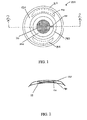
- In one embodiment of the invention, as shown in
FIG. 1 , electro-activecontact lens system 100 has an electro-active element 110 attached to acontact lens 120. Thecontact lens 120 may optionally have acomfort taper 160 adjacent the outer perimeter of thecontact lens 120. The comfort taper may be created by thinning a peripheral edge at the outer perimeter of thecontact lens 120. Thecomfort taper 160 may reduce sensitivity of the eye or eyelid to the electro-activecontact lens system 100 when worn. - A
rangefinder 130, which as described may be integral with a controller, is positioned at or near a horizontal meridian of thecontact lens system 100 so therangefinder 130 is between the palpebral fissure of the eyelid when thecontact lens system 100 is worn, with therangefinder 130 typically within about plus or minus forty-five degrees of the horizontal meridian. Preferably, therangefinder 130 is within about plus or minus fifteen degrees of the horizontal meridian and most preferably is within about plus or minus ten degrees of the horizontal meridian. Therangefinder 130 may be placed at any radial distance from the center of thecontact lens system 100. In certain embodiments, therangefinder 130 is placed outside of the vision correction area of thecontact lens system 100 to interfere as little as possible with the wearer's vision. - Once the
rangefinder 130 is placed at a desired location either on the surface or in the bulk of thecontact lens 120, thecontact lens system 100 may be stabilized to prevent movement and/or rotation of thecontact lens system 100 and to maintain therangefinder 130 between the palpebral fissure of the eyelids when thecontact lens system 100 is worn. Thecontact lens system 100 may be stabilized through the placement of a plurality of stabilizing pieces 140,145 on or in thecontact lens 120. In certain exemplary embodiments, these stabilizing pieces 140,145 may be prism weights, slab-offs, or a combination of the two. The stabilizing pieces 140,145 maintain the orientation of thecontact lens system 100 when thecontact lens system 100 is worn on the eye, substantially preventing thecontact lens system 100 from rotating, which may cause therangefinder 130 to rotate to a concealed location behind the eyelid. - Prism weights typically increase in thickness as the radial distance from the center of the contact lens increases. The thicker portions of the prism weight contact the lower eyelid and stabilize lens rotation by creating a concentration of increased mass at the base of the
contact lens 120. Alternatively, slab-off techniques involve modifying both the superior and inferior surfaces of the contact lens with a decreased thickness as the radial distance from the center of the contact lens increases such that the upper and lower eyelids squeeze the contact lens towards the eye's surface in opposite directions. - It should be appreciated that the stabilizing pieces 140,145 may be of any shape and size adapted to stabilize the
contact lens system 100 without substantially interfering with the vision of the wearer. For example, although each of the stabilizing pieces 140,145 shown inFIG. 1 , are shown as single, crescent shaped pieces, thecontact lens system 100 may be stabilized by a series of several smaller stabilizing pieces arranged to produce a similar stabilization effect. In this way, it should further be appreciated that any number of combinations using one or more stabilizing pieces to stabilize thecontact lens system 100 may be incorporated in various embodiments of the invention. - As shown in
FIG. 1 , thecontact lens system 100 includes a fixed distanceoptical region 150 for the correction of distance vision. The distance vision correction provided by viewing through an area of thecontact lens system 100 in the fixed distanceoptical region 150 is in addition to electro-active vision correction provided by the electro-active element 110 for focal lengths other than distance vision. Together, these areas make up the total vision correction area provided by thecontact lens system 100. In the event that the electro-active element 110 were to fail for any reason, for example if a loss of power caused the applied voltage to stop flowing through the electro-active element, the fixed distanceoptical region 150 allows the wearer to continue to have vision correction for distance vision. Maintaining distance vision is important because loss of all vision correction could have dangerous consequences such as, for example, if the electro-active element 110 were to fail while the wearer was driving. - The
contact lens 120 may comprise either one or both of an optic portion and a non-optic portion. If thecontact lens 120 contains an optic portion, the optic portion includes the fixed distanceoptical region 150 of thecontact lens system 100. The non-optic portion of thecontact lens 120 provides mechanical support for thecontact lens system 100, and may include one or more stabilizing pieces 140,145. It should be appreciated, however, that in certain embodiments theentire contact lens 120 may have a fixed optic power, although in these embodiments, vision correction may not be provided outside of the area of thecontact lens 120 which covers the pupil. - The
contact lens 120 is substantially circular from a frontal view as shown inFIG.1 and has a concave side suitable for matching the curvature of an eye. Size of thecontact lens 120 may vary depending on certain physical attributes of the wearer to be fitted with thecontact lens system 100, such as the age of the wearer or the size or curvature of the wearer's eye, for example. Typically, the total vision correction area of thecontact lens system 100 is substantially circular and is about 4 mm to about 10mm, preferably about 5 mm to about 8 mm, in diameter. - Electrical power may be provided to the electro-
active element 110, as well as therangefinder 130 and controller by affixing aconformal power source 190, such as a battery, capacitor, or other power storage device, for example, to thecontact lens system 100. Theconformal power source 190 is a th in film formed to the shape of thecontact lens 120. Thepower source 190 may be ring shaped and affixed to thecontact lens 120 outside of the vision correction area, which may spread the weight of the power source evenly across thecontact lens 120, without interfering with the wearer's vision. It should be appreciated that in some embodiments, thepower source 190 may not be ring shaped, but instead may be affixed to thecontact lens 120 as a stabilizingpiece 145. In these embodiments, the weight of thepower source 190 may be act as a counterbalance to further stabilize thecontact lens system 100 and maintain therangefinder 130 between the palpebral fissure. - The
power source 190 may provide electrical power which has been previously stored such as in a battery. Alternatively, thepower source 190 may convert kinetic energy from movement of the eye into electric energy using electro-mechanical conversion techniques employing, by way of example only, thin films of transparent piezoelectric polymers. Thepower source 190 could also be produced by the conversion of light into electricity using a thin photovoltaic cell produced from, by way of example only, transparent photovoltaic polymeric films. - The electro-
active element 110 provides electro-active vision correction for at least one focal length. This may include electro-active near and/or intermediate vision, which are the most common focal lengths required by a wearer needing vision correction for multiple focal lengths. Further, intermediate vision may be either or both of near intermediate vision and far intermediate vision. In these embodiments, distance vision is provided by thecontact lens 120, with the exception of the use of adaptive optics to electro-actively correct non-conventional refractive error in the wearer's distance vision by activating only certain portions of the electro-active element. Eliminating non-conventional refractive error may correct the wearer's vision to better than 20/20, up to and including correcting the wearer's vision to better than 20/10. - The area of the
contact lens system 100 for vision correction provided by the electro-active element 110 may be as large as or smaller than the vision correction area provided by the fixed distanceoptical region 150. In at least one embodiment in which the area of the electro-active element 110 is smaller than the fixed distanceoptical region 150, the electro-active element 110 covers at least a portion of the pupil, and is preferably centered over the pupil. - In certain embodiments of the invention, the electro-
active element 110 is encapsulated prior to attaching it to thecontact lens 120. An example of an encapsulatedelement 110 is shown inFIG. 2 as a cross-sectional view of thecontact lens system 100 shown inFIG1 . Acapsule 115 contains the electro-active element 110. Thecontact lens 120 may be molded around thecapsule 115, such that thecapsule 115 is disposed within the bulk of thecontact lens 120. Thecapsule 115 is substantially circular and is adapted to receive the electro-active element 110. Thecapsule 115 is optically transparent to light and allows a wearer to view through thecapsule 115. - The
capsule 115 is preferably rigid and may be constructed either from non-gas permeable, hydrophobic materials or gas-permeable materials. One example of a suitable non-gas permeable, hydrophobic material includes polymethylmethacrylate (PMMA). - Suitable rigid gas permeable materials include methylmethacrylate (MMA) copolymerized with silicone acrylate, or MMA copolymerized with methacryloxypropyl tris(trimethoxysilane) (TRIS), for example. MMA-TRIS doped with fluoromethacrlyates is a particularly suitable gas permeable material for the
capsule 115. - The
contact lens 120 may be constructed from rigid gas permeable material or a flexible hydrophilic material. Examples of suitable flexible hydrophilic materials include, for example, thermo-set polymer hydrogels such as hydroxyethyl methacrylate (HEMA), HEMA cross-linked with either ethylene dimethacrylate (EDMA) or ethylene glycolmonogethacrylate (EGDMA), or silicone based polymers such as polydimethylsiloxane (PDMS). - Optical grade hydrophilic, gas permeable and non-gas permeable materials in addition to those described are well known in the contact lens art. Generally, any of these materials may be used in any combination for construction of the
capsule 115 or thecontact lens 120. However, a rigid, hydrophobicand/or waterproof capsule in combination with either a rigid gas permeable contact lens or a flexible hydrophilic contact lens is preferred. - In some embodiments, the
rangefinder 130, as well as the controller and the power source, may be sealed in thecapsule 115 along with the electro-active element 110, such that all electronic components of thecontact lens system 100 are contained in thecapsule 115. This may have the advantage of decreasing the cost of manufacture as the electronic components can be manufactured and encapsulated separately. Additionally, thecapsule 115 may be constructed of a hydrophobic or water proof material, or sealed with a water proof sealant, which may provide the advantage of protecting the electronic components from being affected by tears or other secretions of the eye. If constructed separately, thecapsule 115 may later be attached to thecontact lens 120 to create thecontact lens system 100 without the need to separately attach therangefinder 130 to thecontact lens 120. It should be appreciated, however, that placement of therangefinder 130 in thecapsule 115 is not required and it may be placed anywhere on or in thecontact lens 120 outside of thecapsule 115. In this case, therangefinder 130 is connected to the electro-active element 110 via conductors which pass out of thecapsule 115 into thecontact lens 120 to therangefinder 130. - In some embodiments, as shown in
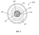
FIG. 3 , it may be desirable to use only a single stabilizingpiece 345, such as a single slab-off or prism weight, for example, to stabilize thecontact lens system 300. At least a portion of the single stabilizingpiece 345 is typically attached below the horizontal meridian of thecontact lens 320. As shown inFIG. 3 , the area of thecontact lens system 300 potentially obscured by including additional stabilizing pieces is decreased. As a result, a larger area of thecontact lens system 300 may be used to provide optical power for vision correction. Availability of additional lens area to provide vision correction may be particularly advantageous in applications such as night vision or other low light settings, for example. In decreased light, pupil dilation may expand the pupil outside of a small vision correction area of acontact lens system 300, creating the possibility of blurred or distorted vision. - In still another exemplary embodiment, as shown in
FIG. 4a , thecontact lens system 400 is stabilized in an alternative manner without the use of stabilizing pieces attached to thecontact lens 420. Instead, thecontact lens system 400 is stabilized by atruncated contact lens 420. Thecontact lens 420 is truncated along achord 470 which is below and substantially parallel, within about 5 degrees, to the horizontal meridian of thecontact lens 420. Typically, thechord 470 along which thecontact lens 420 is truncated is outside of the capsule containing the electro-active element 410. Preferably, thechord 470 along which thecontact lens 420 is truncated does not touch any portion of thecontact lens system 400 which covers the pupil when thecontact lens system 400 is worn and which provides vision correction to the wearer. Typically, about five to about fifteen percent of thecontact lens 420 may be truncated to stabilize thecontact lens system 400, although more or less of thecontact lens 420 may be truncated based on the particular vision needs of the wearer. - Truncation of the
contact lens 420 may be sufficient by itself to stabilize thecontact lens system 400 and maintain therangefinder 430 between the palpebral fissure of the eyelids when thecontact lens system 400 is worn. Alternatively, one or more stabilizingpieces 445, such as slab-offs or prism weights, may be used in combination with thetruncated contact lens 420, as shown inFIG. 4b , to further stabilize thecontact lens system 400. In this embodiment, the truncation is preferably minimal such that a slab-off or prism weight may be attached to thecontact lens 420 without overlapping the area of thecontact lens system 400 which provides vision correction. - In certain embodiments, such as when vision correction for a wearer of an electro- active contact lens system additionally requires correction of astigmatism, the contact lens system may also include a toric power as further illustrated in
FIG 4a . In these embodiments thecontact lens system 400 is stabilized to maintain the orientation of thetoric axis 480 of thecontact lens 420 as well as maintaining the location of therangefinder 430. Preferably, thetoric axis 480 is set prior to placing therangefinder 430 on thecontact lens 420, such as during the initial manufacture of thecontact lens 420. Alternatively, therangefinder 430 may be placed on thecontact lens 420 and stabilized first, followed by orienting thetoric axis 480 relative to the orientation of therangefinder 430. - In certain embodiments, the contact lens produces little or no optic power and the distance vision correction provided by the fixed distance optical region of the contact lens system may be provided instead by the capsule containing the electro-active element. The capsule may be manufactured and surfaced to provide an optical power for distance vision correction directly. As shown in
FIG. 5 , the contact lens is askirt 525 constructed of hydrophilic material, forming a ring around the capsule550, which may help tear flow and decrease eyelid sensitivity to thecapsule 550. Thecontact lens skirt 525 is attached to thecapsule 550 only at the capsule's outer perimeter 527. - The
capsule 550 has a radius of curvature which is surfaced to create an index of refraction that matches a prescription of the wearer for distance vision correction. The embodiment shown inFIG. 5 has acapsule 550 which is not disposed in the bulk of the contact lens, but rather is surrounded by acontact lens skirt 525. Thecontact lens system 500 may be stabilized by slab-offs, prism weights,and/or truncation in the same manner as described elsewhere. - In still other embodiments, the fixed distance optical power of the contact lens system may be provided by a combination of the contact lens and the capsule. For example, the capsule may be surfaced to have an index of refraction and placed in the bulk of a contact lens also having an index refraction. Together, the indices of refraction may be additive to provide a fixed distance optical power to correct the distance vision of the wearer.
- It should be appreciated that in addition to prism weights, slab-offs and truncation, all of which have been discussed in the exemplary embodiments herein, various other methods may be used in stabilizing multi-focal and toric contact lenses. Accordingly, these methods when applied to the embodiments described herein are considered within the scope of the present invention.
- The present invention is not to be limited in scope by the specific embodiments described herein. Indeed, various modifications of the present invention, in addition to those described herein, will be apparent to those of ordinary skill in the art from the foregoing description and accompanying drawings. Thus, such modifications are intended to fall within the scope of the following appended claims. Further, although the present invention has been described herein in the context of a particular implementation in a particular environment for a particular purpose, those of ordinary skill in the art will recognize that its usefulness is not limited thereto and that the present invention can be beneficially implemented in any number of environments for any number of purposes. Accordingly, the claims set forth below should be construed in view of the full breath and spirit of the present invention as disclosed herein.
Claims (8)
- An electro-active contact lens that includes an electro-active element, a view detector in communication with the electro-active element, and a power source that provides power to the electro-active element, wherein the electro-active element and the view detector are contained within a capsule.
- An electro-active contact lens system comprising: a contact lens including an electro-active element; a view detector in communication with the electro-active element; and a power source to provide power to the electro-active element, wherein the view detector comprises a tilt switch.
- An electro-active contact lens system comprising: a contact lens including an electro-active element; a view detector in communication with the electro-active element; and a power source to provide power to the electro-active element, wherein the view detector comprises one of a micro gyroscope or micro accelerometer.
- An electro-active contact lens that includes an electro-active element, a view detector in communication with the electro-active element, a power source that provides power to the electro-active element, and a means for stabilizing the view detector between a palpebral fissure of a patient's eye when the electro-active contact lens is worn by the patient.
- The electro-active contact lens of claim 3 wherein the view detector comprises a rangefinder.
- The electro-active contact lens of claim 3 wherein the view detector comprises a tilt switch.
- The electro-active contact lens of claim 3 wherein the view detector comprises a micro-gyroscope.
- The electro-active contact lens of claim 3 wherein the power source is a conformal battery.
Applications Claiming Priority (7)
| Application Number | Priority Date | Filing Date | Title |
|---|---|---|---|
| US40235702P | 2002-08-09 | 2002-08-09 | |
| US40309602P | 2002-08-13 | 2002-08-13 | |
| US10/263,707 US20030210377A1 (en) | 2001-10-05 | 2002-10-04 | Hybrid electro-active lens |
| US10/281,204 US6733130B2 (en) | 1999-07-02 | 2002-10-28 | Method for refracting and dispensing electro-active spectacles |
| US10/387,143 US7023594B2 (en) | 2000-06-23 | 2003-03-12 | Electro-optic lens with integrated components |
| US10/422,128 US6857741B2 (en) | 2002-01-16 | 2003-04-24 | Electro-active multi-focal spectacle lens |
| EP03785296A EP1546787A4 (en) | 2002-08-09 | 2003-08-08 | Electro-active contact lens system |
Related Parent Applications (2)
| Application Number | Title | Priority Date | Filing Date |
|---|---|---|---|
| EP03785296A Division EP1546787A4 (en) | 2002-08-09 | 2003-08-08 | Electro-active contact lens system |
| EP03785296.9 Division | 2003-08-08 |
Publications (3)
| Publication Number | Publication Date |
|---|---|
| EP1947501A2 true EP1947501A2 (en) | 2008-07-23 |
| EP1947501A3 EP1947501A3 (en) | 2008-12-17 |
| EP1947501B1 EP1947501B1 (en) | 2012-04-25 |
Family
ID=31721932
Family Applications (2)
| Application Number | Title | Priority Date | Filing Date |
|---|---|---|---|
| EP08103859A Expired - Lifetime EP1947501B1 (en) | 2002-08-09 | 2003-08-08 | Electro-active contact lens system |
| EP03785296A Withdrawn EP1546787A4 (en) | 2002-08-09 | 2003-08-08 | Electro-active contact lens system |
Family Applications After (1)
| Application Number | Title | Priority Date | Filing Date |
|---|---|---|---|
| EP03785296A Withdrawn EP1546787A4 (en) | 2002-08-09 | 2003-08-08 | Electro-active contact lens system |
Country Status (9)
| Country | Link |
|---|---|
| EP (2) | EP1947501B1 (en) |
| JP (1) | JP2005535942A (en) |
| KR (1) | KR20050025624A (en) |
| CN (1) | CN1675575A (en) |
| AU (1) | AU2003263881A1 (en) |
| BR (1) | BR0313063A (en) |
| CA (1) | CA2494934A1 (en) |
| DK (1) | DK1947501T3 (en) |
| WO (1) | WO2004015460A2 (en) |
Cited By (34)
| Publication number | Priority date | Publication date | Assignee | Title |
|---|---|---|---|---|
| US8760759B1 (en) | 2009-08-10 | 2014-06-24 | Exelis, Inc. | System and method for binary focus in night vision devices |
| US8909311B2 (en) | 2012-08-21 | 2014-12-09 | Google Inc. | Contact lens with integrated pulse oximeter |
| EP2848979A3 (en) * | 2013-09-17 | 2015-08-19 | Johnson & Johnson Vision Care, Inc. | Variable optic ophthalmic device including liquid crystal elements |
| US9335562B2 (en) | 2013-09-17 | 2016-05-10 | Johnson & Johnson Vision Care, Inc. | Method and apparatus for ophthalmic devices comprising dielectrics and liquid crystal polymer networks |
| US9366881B2 (en) | 2013-09-17 | 2016-06-14 | Johnson & Johnson Vision Care, Inc. | Method and apparatus for ophthalmic devices including shaped liquid crystal polymer networked regions of liquid crystal |
| US9442309B2 (en) | 2013-09-17 | 2016-09-13 | Johnson & Johnson Vision Care, Inc. | Method and apparatus for ophthalmic devices comprising dielectrics and nano-scaled droplets of liquid crystal |
| US9500882B2 (en) | 2013-09-17 | 2016-11-22 | Johnson & Johnson Vision Care, Inc. | Variable optic ophthalmic device including shaped liquid crystal elements with nano-scaled droplets of liquid crystal |
| US9541772B2 (en) | 2013-09-17 | 2017-01-10 | Johnson & Johnson Vision Care, Inc. | Methods and apparatus for ophthalmic devices including cycloidally oriented liquid crystal layers |
| US9592116B2 (en) | 2013-09-17 | 2017-03-14 | Johnson & Johnson Vision Care, Inc. | Methods and apparatus for ophthalmic devices including cycloidally oriented liquid crystal layers |
| US9636016B1 (en) | 2013-01-25 | 2017-05-02 | Verily Life Sciences Llc | Eye-mountable devices and methods for accurately placing a flexible ring containing electronics in eye-mountable devices |
| US9654674B1 (en) | 2013-12-20 | 2017-05-16 | Verily Life Sciences Llc | Image sensor with a plurality of light channels |
| US9662054B2 (en) | 2013-06-17 | 2017-05-30 | Verily Life Sciences Llc | Symmetrically arranged sensor electrodes in an ophthalmic electrochemical sensor |
| US9685689B1 (en) | 2013-06-27 | 2017-06-20 | Verily Life Sciences Llc | Fabrication methods for bio-compatible devices |
| US9690116B2 (en) | 2011-12-23 | 2017-06-27 | Johnson & Johnson Vision Care, Inc. | Variable optic ophthalmic device including liquid crystal elements |
| US9696564B1 (en) | 2012-08-21 | 2017-07-04 | Verily Life Sciences Llc | Contact lens with metal portion and polymer layer having indentations |
| US9724027B2 (en) | 2012-10-12 | 2017-08-08 | Verily Life Sciences Llc | Microelectrodes in an ophthalmic electrochemical sensor |
| US9735892B1 (en) | 2012-07-26 | 2017-08-15 | Verily Life Sciences Llc | Employing optical signals for power and/or communication |
| US9737248B1 (en) | 2012-09-11 | 2017-08-22 | Verily Life Sciences Llc | Cancellation of a baseline current signal via current subtraction within a linear relaxation oscillator-based current-to-frequency converter circuit |
| US9757056B1 (en) | 2012-10-26 | 2017-09-12 | Verily Life Sciences Llc | Over-molding of sensor apparatus in eye-mountable device |
| US9775513B1 (en) | 2012-09-28 | 2017-10-03 | Verily Life Sciences Llc | Input detection system |
| US9789655B1 (en) | 2014-03-14 | 2017-10-17 | Verily Life Sciences Llc | Methods for mold release of body-mountable devices including microelectronics |
| US9814387B2 (en) | 2013-06-28 | 2017-11-14 | Verily Life Sciences, LLC | Device identification |
| US9869885B2 (en) | 2013-09-17 | 2018-01-16 | Johnson & Johnson Vision Care, Inc. | Method and apparatus for ophthalmic devices including gradient-indexed liquid crystal layers and shaped dielectric layers |
| US9880398B2 (en) | 2013-09-17 | 2018-01-30 | Johnson & Johnson Vision Care, Inc. | Method and apparatus for ophthalmic devices including gradient-indexed and shaped liquid crystal layers |
| US9884180B1 (en) | 2012-09-26 | 2018-02-06 | Verily Life Sciences Llc | Power transducer for a retinal implant using a contact lens |
| US9948895B1 (en) | 2013-06-18 | 2018-04-17 | Verily Life Sciences Llc | Fully integrated pinhole camera for eye-mountable imaging system |
| US9965583B2 (en) | 2012-09-25 | 2018-05-08 | Verily Life Sciences, LLC | Information processing method |
| US10004457B2 (en) | 2013-01-15 | 2018-06-26 | Verily Life Sciences Llc | Encapsulated electronics |
| US10010270B2 (en) | 2012-09-17 | 2018-07-03 | Verily Life Sciences Llc | Sensing system |
| US10120203B2 (en) | 2012-07-26 | 2018-11-06 | Verliy Life Sciences LLC | Contact lenses with hybrid power sources |
| US10386653B2 (en) | 2012-12-21 | 2019-08-20 | Johnson & Johnson Vision Care, Inc. | Variable optic ophthalmic device including liquid crystal elements |
| US10859868B2 (en) | 2017-08-11 | 2020-12-08 | Coopervision International Limited | Flexible liquid crystal cells and lenses |
| US11003016B2 (en) | 2018-09-21 | 2021-05-11 | Coopervision International Limited | Flexible, adjustable lens power liquid crystal cells and lenses |
| EP3899650A4 (en) * | 2018-12-20 | 2022-09-07 | Tectus Corporation | Dynamic presbyopia correction in electronic contact lenses |
Families Citing this family (96)
| Publication number | Priority date | Publication date | Assignee | Title |
|---|---|---|---|---|
| US7988286B2 (en) | 1999-07-02 | 2011-08-02 | E-Vision Llc | Static progressive surface region in optical communication with a dynamic optic |
| US9801709B2 (en) | 2004-11-02 | 2017-10-31 | E-Vision Smart Optics, Inc. | Electro-active intraocular lenses |
| US8931896B2 (en) | 2004-11-02 | 2015-01-13 | E-Vision Smart Optics Inc. | Eyewear including a docking station |
| US8778022B2 (en) | 2004-11-02 | 2014-07-15 | E-Vision Smart Optics Inc. | Electro-active intraocular lenses |
| ES2961305T3 (en) * | 2004-11-02 | 2024-03-11 | E Vision Smart Optics Inc | Electroactive lenses |
| JP4752309B2 (en) * | 2005-04-07 | 2011-08-17 | ソニー株式会社 | Image display apparatus and method |
| US20060290882A1 (en) * | 2005-06-27 | 2006-12-28 | Paragon Vision Sciences, Inc. | Laminated contact lens |
| US9122083B2 (en) | 2005-10-28 | 2015-09-01 | E-Vision Smart Optics, Inc. | Eyewear docking station and electronic module |
| AR061449A1 (en) * | 2006-06-12 | 2008-08-27 | Pixeloptics Inc | STATIC PROGRESSIVE SURFACE REGION IN OPTICAL COMMUNICATION WITH A DYNAMIC OPTICS |
| AR064985A1 (en) | 2007-01-22 | 2009-05-06 | E Vision Llc | FLEXIBLE ELECTROACTIVE LENS |
| WO2009042289A1 (en) * | 2007-08-02 | 2009-04-02 | Ocular Optics, Inc. | Multi-focal intraocular lens system and methods |
| EP2271964A4 (en) | 2008-03-18 | 2017-09-20 | Mitsui Chemicals, Inc. | Advanced electro-active optic device |
| US7931832B2 (en) * | 2008-03-31 | 2011-04-26 | Johnson & Johnson Vision Care, Inc. | Ophthalmic lens media insert |
| US9296158B2 (en) * | 2008-09-22 | 2016-03-29 | Johnson & Johnson Vision Care, Inc. | Binder of energized components in an ophthalmic lens |
| US9675443B2 (en) | 2009-09-10 | 2017-06-13 | Johnson & Johnson Vision Care, Inc. | Energized ophthalmic lens including stacked integrated components |
| US20100078837A1 (en) * | 2008-09-29 | 2010-04-01 | Pugh Randall B | Apparatus and method for formation of an energized ophthalmic device |
| US9427920B2 (en) * | 2008-09-30 | 2016-08-30 | Johnson & Johnson Vision Care, Inc. | Energized media for an ophthalmic device |
| US8348424B2 (en) * | 2008-09-30 | 2013-01-08 | Johnson & Johnson Vision Care, Inc. | Variable focus ophthalmic device |
| US9375885B2 (en) * | 2008-10-31 | 2016-06-28 | Johnson & Johnson Vision Care, Inc. | Processor controlled ophthalmic device |
| US9375886B2 (en) * | 2008-10-31 | 2016-06-28 | Johnson & Johnson Vision Care Inc. | Ophthalmic device with embedded microcontroller |
| CN106226892B (en) * | 2009-01-15 | 2022-01-18 | E-视觉智能光学公司 | Electro-active focus and zoom system |
| SG10201508383QA (en) | 2010-10-11 | 2015-11-27 | Adlens Beacon Inc | Fluid filled adjustable contact lenses |
| US8950862B2 (en) | 2011-02-28 | 2015-02-10 | Johnson & Johnson Vision Care, Inc. | Methods and apparatus for an ophthalmic lens with functional insert layers |
| US9233513B2 (en) | 2011-03-18 | 2016-01-12 | Johnson & Johnson Vision Care, Inc. | Apparatus for manufacturing stacked integrated component media inserts for ophthalmic devices |
| US10451897B2 (en) | 2011-03-18 | 2019-10-22 | Johnson & Johnson Vision Care, Inc. | Components with multiple energization elements for biomedical devices |
| US9698129B2 (en) | 2011-03-18 | 2017-07-04 | Johnson & Johnson Vision Care, Inc. | Stacked integrated component devices with energization |
| US9804418B2 (en) | 2011-03-21 | 2017-10-31 | Johnson & Johnson Vision Care, Inc. | Methods and apparatus for functional insert with power layer |
| SG11201404174SA (en) * | 2012-01-26 | 2014-10-30 | Johnson & Johnson Vision Care | Stacked integrated component media insert for an ophthalmic device |
| US8857983B2 (en) | 2012-01-26 | 2014-10-14 | Johnson & Johnson Vision Care, Inc. | Ophthalmic lens assembly having an integrated antenna structure |
| KR101969289B1 (en) * | 2012-01-26 | 2019-04-17 | 존슨 앤드 존슨 비젼 케어, 인코포레이티드 | Energized ophthalmic lens including stacked integrated components |
| US8798332B2 (en) | 2012-05-15 | 2014-08-05 | Google Inc. | Contact lenses |
| US10712588B2 (en) | 2012-05-25 | 2020-07-14 | Paragon Crt Company Llc | Contact lens having a space |
| EP2855132B1 (en) | 2012-05-25 | 2019-10-16 | Paragon CRT Company LLC | Multicomponent optical device having a space |
| US10049275B2 (en) | 2012-05-25 | 2018-08-14 | Paragon Crt Company Llc | Multicomponent optical device for visual and audible translation and recognition |
| US8857981B2 (en) | 2012-07-26 | 2014-10-14 | Google Inc. | Facilitation of contact lenses with capacitive sensors |
| US9298020B1 (en) | 2012-07-26 | 2016-03-29 | Verily Life Sciences Llc | Input system |
| US8919953B1 (en) | 2012-08-02 | 2014-12-30 | Google Inc. | Actuatable contact lenses |
| US9111473B1 (en) | 2012-08-24 | 2015-08-18 | Google Inc. | Input system |
| US8820934B1 (en) | 2012-09-05 | 2014-09-02 | Google Inc. | Passive surface acoustic wave communication |
| US20140192315A1 (en) | 2012-09-07 | 2014-07-10 | Google Inc. | In-situ tear sample collection and testing using a contact lens |
| US9326710B1 (en) | 2012-09-20 | 2016-05-03 | Verily Life Sciences Llc | Contact lenses having sensors with adjustable sensitivity |
| US8870370B1 (en) | 2012-09-24 | 2014-10-28 | Google Inc. | Contact lens that facilitates antenna communication via sensor impedance modulation |
| US8960898B1 (en) | 2012-09-24 | 2015-02-24 | Google Inc. | Contact lens that restricts incoming light to the eye |
| US8989834B2 (en) | 2012-09-25 | 2015-03-24 | Google Inc. | Wearable device |
| US8979271B2 (en) | 2012-09-25 | 2015-03-17 | Google Inc. | Facilitation of temperature compensation for contact lens sensors and temperature sensing |
| US8821811B2 (en) | 2012-09-26 | 2014-09-02 | Google Inc. | In-vitro contact lens testing |
| US8960899B2 (en) | 2012-09-26 | 2015-02-24 | Google Inc. | Assembling thin silicon chips on a contact lens |
| US8985763B1 (en) | 2012-09-26 | 2015-03-24 | Google Inc. | Contact lens having an uneven embedded substrate and method of manufacture |
| US9176332B1 (en) | 2012-10-24 | 2015-11-03 | Google Inc. | Contact lens and method of manufacture to improve sensor sensitivity |
| SG2013091087A (en) | 2013-01-09 | 2014-08-28 | Johnson & Johnson Vision Care | Multi-piece insert device with glue seal for ophthalmic devices |
| US9289954B2 (en) | 2013-01-17 | 2016-03-22 | Verily Life Sciences Llc | Method of ring-shaped structure placement in an eye-mountable device |
| US20140209481A1 (en) | 2013-01-25 | 2014-07-31 | Google Inc. | Standby Biasing Of Electrochemical Sensor To Reduce Sensor Stabilization Time During Measurement |
| US9671619B2 (en) * | 2013-02-28 | 2017-06-06 | Johnson & Johnson Vision Care, Inc. | Electronic ophthalmic lens with eye gaze sensor |
| US9323073B2 (en) * | 2013-02-28 | 2016-04-26 | Johnson & Johnson Vision Care, Inc. | Electronic ophthalmic lens with emitter-detector pair sensor |
| US9778492B2 (en) | 2013-02-28 | 2017-10-03 | Johnson & Johnson Vision Care, Inc. | Electronic ophthalmic lens with lid position sensor |
| US9050185B2 (en) * | 2013-02-28 | 2015-06-09 | Johnson & Johnson Vision Care, Inc. | Electronic ophthalmic lens with pupil convergence sensor |
| US9581832B2 (en) * | 2013-03-15 | 2017-02-28 | Johnson & Johnson Vision Care, Inc. | Method and apparatus for encapsulating a rigid insert in a contact lens for correcting vision in astigmatic patients |
| US8974055B2 (en) | 2013-03-15 | 2015-03-10 | Johnson & Johnson Vision Care, Inc. | Method and apparatus for encapsulating a rigid insert in a contact lens for correcting vision in astigmatic patients |
| US9465236B2 (en) * | 2013-03-15 | 2016-10-11 | Johnson & Johnson Vision Care, Inc. | Ophthalmic devices incorporating photonic elements |
| US9164297B2 (en) * | 2013-03-15 | 2015-10-20 | Johnson & Johnson Vision Care, Inc. | Ophthalmic devices with stabilization features |
| US9316848B2 (en) * | 2013-03-15 | 2016-04-19 | Johnson & Johnson Vision Care, Inc. | Ophthalmic devices with stabilization features |
| US9161712B2 (en) | 2013-03-26 | 2015-10-20 | Google Inc. | Systems and methods for encapsulating electronics in a mountable device |
| US9113829B2 (en) | 2013-03-27 | 2015-08-25 | Google Inc. | Systems and methods for encapsulating electronics in a mountable device |
| US9116363B2 (en) * | 2013-05-17 | 2015-08-25 | Johnson & Johnson Vision Care, Inc. | System and method of programming an energized ophthalmic lens |
| US20140371560A1 (en) | 2013-06-14 | 2014-12-18 | Google Inc. | Body-Mountable Devices and Methods for Embedding a Structure in a Body-Mountable Device |
| US9492118B1 (en) | 2013-06-28 | 2016-11-15 | Life Sciences Llc | Pre-treatment process for electrochemical amperometric sensor |
| US9307901B1 (en) | 2013-06-28 | 2016-04-12 | Verily Life Sciences Llc | Methods for leaving a channel in a polymer layer using a cross-linked polymer plug |
| US8833934B1 (en) | 2013-06-28 | 2014-09-16 | Google Inc. | Devices and methods for a contact lens with an outward facing light source |
| US9668646B2 (en) | 2013-06-28 | 2017-06-06 | Verily Life Sciences Llc | Devices and methods for a contact lens with an inward facing light source |
| US9028772B2 (en) | 2013-06-28 | 2015-05-12 | Google Inc. | Methods for forming a channel through a polymer layer using one or more photoresist layers |
| US9996151B2 (en) * | 2013-07-19 | 2018-06-12 | Sony Corporation | Detecting eye movement based on a wearable detection apparatus |
| US9185486B2 (en) * | 2013-08-27 | 2015-11-10 | Johnson & Johnson Vision Care, Inc. | Ophthalmic lens with micro-acoustic elements |
| US9170646B2 (en) * | 2013-09-04 | 2015-10-27 | Johnson & Johnson Vision Care, Inc. | Ophthalmic lens system capable of interfacing with an external device |
| US9572522B2 (en) | 2013-12-20 | 2017-02-21 | Verily Life Sciences Llc | Tear fluid conductivity sensor |
| US9625738B2 (en) | 2014-01-31 | 2017-04-18 | Synergeyes, Inc. | Hybrid contact lens |
| US9366570B1 (en) | 2014-03-10 | 2016-06-14 | Verily Life Sciences Llc | Photodiode operable in photoconductive mode and photovoltaic mode |
| US9184698B1 (en) | 2014-03-11 | 2015-11-10 | Google Inc. | Reference frequency from ambient light signal |
| EP2952850A1 (en) * | 2014-06-03 | 2015-12-09 | Optotune AG | Optical device, particularly for tuning the focal length of a lens of the device by means of optical feedback |
| US9690118B2 (en) | 2014-06-13 | 2017-06-27 | Verily Life Sciences Llc | Eye-mountable device to provide automatic accommodation and method of making same |
| US9941547B2 (en) | 2014-08-21 | 2018-04-10 | Johnson & Johnson Vision Care, Inc. | Biomedical energization elements with polymer electrolytes and cavity structures |
| US9599842B2 (en) | 2014-08-21 | 2017-03-21 | Johnson & Johnson Vision Care, Inc. | Device and methods for sealing and encapsulation for biocompatible energization elements |
| US10627651B2 (en) | 2014-08-21 | 2020-04-21 | Johnson & Johnson Vision Care, Inc. | Methods and apparatus to form biocompatible energization primary elements for biomedical devices with electroless sealing layers |
| US9383593B2 (en) | 2014-08-21 | 2016-07-05 | Johnson & Johnson Vision Care, Inc. | Methods to form biocompatible energization elements for biomedical devices comprising laminates and placed separators |
| US10361404B2 (en) | 2014-08-21 | 2019-07-23 | Johnson & Johnson Vision Care, Inc. | Anodes for use in biocompatible energization elements |
| US10381687B2 (en) | 2014-08-21 | 2019-08-13 | Johnson & Johnson Vision Care, Inc. | Methods of forming biocompatible rechargable energization elements for biomedical devices |
| US9793536B2 (en) | 2014-08-21 | 2017-10-17 | Johnson & Johnson Vision Care, Inc. | Pellet form cathode for use in a biocompatible battery |
| US10361405B2 (en) | 2014-08-21 | 2019-07-23 | Johnson & Johnson Vision Care, Inc. | Biomedical energization elements with polymer electrolytes |
| US9715130B2 (en) | 2014-08-21 | 2017-07-25 | Johnson & Johnson Vision Care, Inc. | Methods and apparatus to form separators for biocompatible energization elements for biomedical devices |
| EP3288442B1 (en) * | 2015-04-30 | 2024-05-01 | Twenty Twenty Therapeutics LLC | Body-mountable devices with two layers |
| US10345620B2 (en) | 2016-02-18 | 2019-07-09 | Johnson & Johnson Vision Care, Inc. | Methods and apparatus to form biocompatible energization elements incorporating fuel cells for biomedical devices |
| US10353204B2 (en) * | 2016-10-31 | 2019-07-16 | Tectus Corporation | Femtoprojector optical systems |
| US10509238B2 (en) | 2017-04-14 | 2019-12-17 | Verily Life Sciences Llc | Electrowetting opthalmic optics including gas-permeable components |
| CN107272220B (en) * | 2017-08-16 | 2019-11-19 | 北京五环伟业科技有限公司 | Glasses system |
| CN111407227B (en) * | 2019-01-04 | 2021-06-18 | 中国科学院半导体研究所 | Optical intraocular pressure detection device based on corneal contact lens and preparation and use methods |
| CN114839796A (en) * | 2021-02-01 | 2022-08-02 | 上海婷伊美科技有限公司 | Variable-focus hard contact lens and manufacturing method thereof |
| CN114280815A (en) * | 2022-01-07 | 2022-04-05 | 东南大学 | Intelligent contact lens containing flexible circuit and preparation method thereof |
Citations (2)
| Publication number | Priority date | Publication date | Assignee | Title |
|---|---|---|---|---|
| US4601545A (en) | 1984-05-16 | 1986-07-22 | Kern Seymour P | Variable power lens system |
| WO2005007836A1 (en) | 2003-07-15 | 2005-01-27 | Protagen Ag | Regulatory t-cells containing galectins for the therapy and diagnosis of diseases |
Family Cites Families (7)
| Publication number | Priority date | Publication date | Assignee | Title |
|---|---|---|---|---|
| US4373218A (en) * | 1980-11-17 | 1983-02-15 | Schachar Ronald A | Variable power intraocular lens and method of implanting into the posterior chamber |
| US4573774A (en) | 1981-09-28 | 1986-03-04 | Vistakon, Inc. | Soft toric contact lens |
| US4477158A (en) * | 1981-10-15 | 1984-10-16 | Pollock Stephen C | Lens system for variable refraction |
| US5359444A (en) * | 1992-12-24 | 1994-10-25 | Motorola, Inc. | Auto-focusing optical apparatus |
| US5444559A (en) * | 1993-03-26 | 1995-08-22 | Warnar; Robert B. J. | Method and apparatus for controlling optical characteristics of a programmable surface medium |
| DE69421394T2 (en) | 1993-04-07 | 2000-02-10 | Ttp Group Plc | SWITCHABLE LENS |
| CA2650681A1 (en) * | 2001-01-17 | 2002-07-25 | E-Vision, L.L.C. | Electro-optic lens with integrated components |
-
2003
- 2003-08-08 CA CA002494934A patent/CA2494934A1/en not_active Abandoned
- 2003-08-08 AU AU2003263881A patent/AU2003263881A1/en not_active Abandoned
- 2003-08-08 JP JP2005506622A patent/JP2005535942A/en active Pending
- 2003-08-08 EP EP08103859A patent/EP1947501B1/en not_active Expired - Lifetime
- 2003-08-08 DK DK08103859.8T patent/DK1947501T3/en active
- 2003-08-08 WO PCT/US2003/025796 patent/WO2004015460A2/en active Application Filing
- 2003-08-08 EP EP03785296A patent/EP1546787A4/en not_active Withdrawn
- 2003-08-08 CN CNA038191768A patent/CN1675575A/en active Pending
- 2003-08-08 BR BR0313063-0A patent/BR0313063A/en not_active IP Right Cessation
- 2003-08-08 KR KR1020057000986A patent/KR20050025624A/en not_active Application Discontinuation
Patent Citations (2)
| Publication number | Priority date | Publication date | Assignee | Title |
|---|---|---|---|---|
| US4601545A (en) | 1984-05-16 | 1986-07-22 | Kern Seymour P | Variable power lens system |
| WO2005007836A1 (en) | 2003-07-15 | 2005-01-27 | Protagen Ag | Regulatory t-cells containing galectins for the therapy and diagnosis of diseases |
Cited By (53)
| Publication number | Priority date | Publication date | Assignee | Title |
|---|---|---|---|---|
| US8760759B1 (en) | 2009-08-10 | 2014-06-24 | Exelis, Inc. | System and method for binary focus in night vision devices |
| US9690116B2 (en) | 2011-12-23 | 2017-06-27 | Johnson & Johnson Vision Care, Inc. | Variable optic ophthalmic device including liquid crystal elements |
| US10256919B1 (en) | 2012-07-26 | 2019-04-09 | Verily Life Sciences Llc | Employing optical signals for power and/or communication |
| US10873401B1 (en) | 2012-07-26 | 2020-12-22 | Verily Life Sciences Llc | Employing optical signals for power and/or communication |
| US9735892B1 (en) | 2012-07-26 | 2017-08-15 | Verily Life Sciences Llc | Employing optical signals for power and/or communication |
| US10120203B2 (en) | 2012-07-26 | 2018-11-06 | Verliy Life Sciences LLC | Contact lenses with hybrid power sources |
| US9696564B1 (en) | 2012-08-21 | 2017-07-04 | Verily Life Sciences Llc | Contact lens with metal portion and polymer layer having indentations |
| US8909311B2 (en) | 2012-08-21 | 2014-12-09 | Google Inc. | Contact lens with integrated pulse oximeter |
| US8971978B2 (en) | 2012-08-21 | 2015-03-03 | Google Inc. | Contact lens with integrated pulse oximeter |
| US9737248B1 (en) | 2012-09-11 | 2017-08-22 | Verily Life Sciences Llc | Cancellation of a baseline current signal via current subtraction within a linear relaxation oscillator-based current-to-frequency converter circuit |
| US10729363B1 (en) | 2012-09-11 | 2020-08-04 | Verily Life Sciences Llc | Cancellation of a baseline current signal via current subtraction within a linear relaxation oscillator-based current-to-frequency converter circuit |
| US10010270B2 (en) | 2012-09-17 | 2018-07-03 | Verily Life Sciences Llc | Sensing system |
| US10932695B2 (en) | 2012-09-17 | 2021-03-02 | Verily Life Sciences Llc | Sensing system |
| US9965583B2 (en) | 2012-09-25 | 2018-05-08 | Verily Life Sciences, LLC | Information processing method |
| US10099049B2 (en) | 2012-09-26 | 2018-10-16 | Verily Life Sciences Llc | Power transducer for a retinal implant using using a contact lens |
| US9884180B1 (en) | 2012-09-26 | 2018-02-06 | Verily Life Sciences Llc | Power transducer for a retinal implant using a contact lens |
| US9775513B1 (en) | 2012-09-28 | 2017-10-03 | Verily Life Sciences Llc | Input detection system |
| US10342424B2 (en) | 2012-09-28 | 2019-07-09 | Verily Life Sciences Llc | Input detection system |
| US9724027B2 (en) | 2012-10-12 | 2017-08-08 | Verily Life Sciences Llc | Microelectrodes in an ophthalmic electrochemical sensor |
| US9757056B1 (en) | 2012-10-26 | 2017-09-12 | Verily Life Sciences Llc | Over-molding of sensor apparatus in eye-mountable device |
| US10386653B2 (en) | 2012-12-21 | 2019-08-20 | Johnson & Johnson Vision Care, Inc. | Variable optic ophthalmic device including liquid crystal elements |
| US10004457B2 (en) | 2013-01-15 | 2018-06-26 | Verily Life Sciences Llc | Encapsulated electronics |
| US9636016B1 (en) | 2013-01-25 | 2017-05-02 | Verily Life Sciences Llc | Eye-mountable devices and methods for accurately placing a flexible ring containing electronics in eye-mountable devices |
| US9662054B2 (en) | 2013-06-17 | 2017-05-30 | Verily Life Sciences Llc | Symmetrically arranged sensor electrodes in an ophthalmic electrochemical sensor |
| US9948895B1 (en) | 2013-06-18 | 2018-04-17 | Verily Life Sciences Llc | Fully integrated pinhole camera for eye-mountable imaging system |
| US9685689B1 (en) | 2013-06-27 | 2017-06-20 | Verily Life Sciences Llc | Fabrication methods for bio-compatible devices |
| US9814387B2 (en) | 2013-06-28 | 2017-11-14 | Verily Life Sciences, LLC | Device identification |
| RU2622462C2 (en) * | 2013-09-17 | 2017-06-15 | Джонсон Энд Джонсон Вижн Кэа, Инк. | Ophthalmic device with variable optical properties, including liquid crystal elements |
| US9592116B2 (en) | 2013-09-17 | 2017-03-14 | Johnson & Johnson Vision Care, Inc. | Methods and apparatus for ophthalmic devices including cycloidally oriented liquid crystal layers |
| US9823490B2 (en) | 2013-09-17 | 2017-11-21 | Johnson & Johnson Vision Care, Inc. | Methods and apparatus for ophthalmic devices including cycloidally oriented liquid crystal layers |
| US9823492B2 (en) | 2013-09-17 | 2017-11-21 | Johnson & Johnson Vision Care, Inc. | Methods and apparatus for ophthalmic devices including cycloidally oriented liquid crystal layers |
| US9835876B2 (en) | 2013-09-17 | 2017-12-05 | Johnson & Johnson Vision Care, Inc. | Methods and apparatus for ophthalmic devices including cycloidally oriented liquid crystal layers |
| US9869885B2 (en) | 2013-09-17 | 2018-01-16 | Johnson & Johnson Vision Care, Inc. | Method and apparatus for ophthalmic devices including gradient-indexed liquid crystal layers and shaped dielectric layers |
| US9880398B2 (en) | 2013-09-17 | 2018-01-30 | Johnson & Johnson Vision Care, Inc. | Method and apparatus for ophthalmic devices including gradient-indexed and shaped liquid crystal layers |
| US9817244B2 (en) | 2013-09-17 | 2017-11-14 | Johnson & Johnson Vision Care, Inc. | Methods and apparatus for ophthalmic devices including cycloidally oriented liquid crystal layers |
| US9817245B2 (en) | 2013-09-17 | 2017-11-14 | Johnson & Johnson Vision Care, Inc. | Methods and apparatus for ophthalmic devices including cycloidally oriented liquid crystal layers |
| US9958704B2 (en) | 2013-09-17 | 2018-05-01 | Johnson & Johnson Vision Care, Inc. | Methods and apparatus for ophthalmic devices including cycloidally oriented liquid crystal layers |
| EP2848979A3 (en) * | 2013-09-17 | 2015-08-19 | Johnson & Johnson Vision Care, Inc. | Variable optic ophthalmic device including liquid crystal elements |
| US9784993B2 (en) | 2013-09-17 | 2017-10-10 | Johnson & Johnson Vision Care, Inc. | Methods and apparatus for ophthalmic devices including cycloidally oriented liquid crystal layers |
| US9335562B2 (en) | 2013-09-17 | 2016-05-10 | Johnson & Johnson Vision Care, Inc. | Method and apparatus for ophthalmic devices comprising dielectrics and liquid crystal polymer networks |
| US9823491B2 (en) | 2013-09-17 | 2017-11-21 | Johnson & Johnson Vision Care, Inc. | Methods and apparatus for ophthalmic devices including cycloidally oriented liquid crystal layers |
| US9541772B2 (en) | 2013-09-17 | 2017-01-10 | Johnson & Johnson Vision Care, Inc. | Methods and apparatus for ophthalmic devices including cycloidally oriented liquid crystal layers |
| US9500882B2 (en) | 2013-09-17 | 2016-11-22 | Johnson & Johnson Vision Care, Inc. | Variable optic ophthalmic device including shaped liquid crystal elements with nano-scaled droplets of liquid crystal |
| US9442309B2 (en) | 2013-09-17 | 2016-09-13 | Johnson & Johnson Vision Care, Inc. | Method and apparatus for ophthalmic devices comprising dielectrics and nano-scaled droplets of liquid crystal |
| RU2594367C2 (en) * | 2013-09-17 | 2016-08-20 | Джонсон Энд Джонсон Вижн Кэа, Инк. | Methods and apparatus for ophthalmic devices including cycloidally oriented liquid crystal layers |
| US9366881B2 (en) | 2013-09-17 | 2016-06-14 | Johnson & Johnson Vision Care, Inc. | Method and apparatus for ophthalmic devices including shaped liquid crystal polymer networked regions of liquid crystal |
| US9654674B1 (en) | 2013-12-20 | 2017-05-16 | Verily Life Sciences Llc | Image sensor with a plurality of light channels |
| US9789655B1 (en) | 2014-03-14 | 2017-10-17 | Verily Life Sciences Llc | Methods for mold release of body-mountable devices including microelectronics |
| US10859868B2 (en) | 2017-08-11 | 2020-12-08 | Coopervision International Limited | Flexible liquid crystal cells and lenses |
| US11860470B2 (en) | 2017-08-11 | 2024-01-02 | Coopervision International Limited | Flexible liquid crystal cells and lenses |
| US11003016B2 (en) | 2018-09-21 | 2021-05-11 | Coopervision International Limited | Flexible, adjustable lens power liquid crystal cells and lenses |
| US11520181B2 (en) | 2018-09-21 | 2022-12-06 | Coopervision International Limited | Flexible, adjustable lens power liquid crystal cells and lenses |
| EP3899650A4 (en) * | 2018-12-20 | 2022-09-07 | Tectus Corporation | Dynamic presbyopia correction in electronic contact lenses |
Also Published As
| Publication number | Publication date |
|---|---|
| CA2494934A1 (en) | 2004-02-19 |
| JP2005535942A (en) | 2005-11-24 |
| WO2004015460A2 (en) | 2004-02-19 |
| BR0313063A (en) | 2005-06-28 |
| DK1947501T3 (en) | 2012-08-06 |
| WO2004015460A3 (en) | 2004-06-24 |
| CN1675575A (en) | 2005-09-28 |
| EP1947501A3 (en) | 2008-12-17 |
| EP1947501B1 (en) | 2012-04-25 |
| AU2003263881A1 (en) | 2004-02-25 |
| EP1546787A4 (en) | 2006-02-08 |
| EP1546787A2 (en) | 2005-06-29 |
| KR20050025624A (en) | 2005-03-14 |
Similar Documents
| Publication | Publication Date | Title |
|---|---|---|
| US6851805B2 (en) | Stabilized electro-active contact lens | |
| EP1947501B1 (en) | Electro-active contact lens system | |
| US20230113330A1 (en) | Flexible electro-active lens | |
| US10598961B2 (en) | Glasses | |
| US20120300171A1 (en) | Programmable Ophthalmic Lenses | |
| US20140327875A1 (en) | Advanced electro-active optic device | |
| US11221488B1 (en) | Tunable and foveated lens systems | |
| KR20220016827A (en) | Active lenses suitable for correcting abnormal refraction of the wearer's eye | |
| ES2386086T3 (en) | Electro active contact lens systems | |
| US20220113558A1 (en) | Contact lens position and rotation control using the pressure of the eyelid margin | |
| AU2015264899B2 (en) | Fluid filled adjustable contact lenses |
Legal Events
| Date | Code | Title | Description |
|---|---|---|---|
| PUAI | Public reference made under article 153(3) epc to a published international application that has entered the european phase |
Free format text: ORIGINAL CODE: 0009012 |
|
| 17P | Request for examination filed |
Effective date: 20080507 |
|
| AC | Divisional application: reference to earlier application |
Ref document number: 1546787 Country of ref document: EP Kind code of ref document: P |
|
| AK | Designated contracting states |
Kind code of ref document: A2 Designated state(s): AT BE BG CH CY CZ DE DK EE ES FI FR GB GR HU IE IT LI LU MC NL PT RO SE SI SK TR |
|
| PUAL | Search report despatched |
Free format text: ORIGINAL CODE: 0009013 |
|
| AK | Designated contracting states |
Kind code of ref document: A3 Designated state(s): AT BE BG CH CY CZ DE DK EE ES FI FR GB GR HU IE IT LI LU MC NL PT RO SE SI SK TR |
|
| 17Q | First examination report despatched |
Effective date: 20090129 |
|
| AKX | Designation fees paid |
Designated state(s): AT BE BG CH CY CZ DE DK EE ES FI FR GB GR HU IE IT LI LU MC NL PT RO SE SI SK TR |
|
| GRAP | Despatch of communication of intention to grant a patent |
Free format text: ORIGINAL CODE: EPIDOSNIGR1 |
|
| GRAS | Grant fee paid |
Free format text: ORIGINAL CODE: EPIDOSNIGR3 |
|
| GRAA | (expected) grant |
Free format text: ORIGINAL CODE: 0009210 |
|
| AC | Divisional application: reference to earlier application |
Ref document number: 1546787 Country of ref document: EP Kind code of ref document: P |
|
| AK | Designated contracting states |
Kind code of ref document: B1 Designated state(s): AT BE BG CH CY CZ DE DK EE ES FI FR GB GR HU IE IT LI LU MC NL PT RO SE SI SK TR |
|
| REG | Reference to a national code |
Ref country code: GB Ref legal event code: FG4D |
|
| REG | Reference to a national code |
Ref country code: CH Ref legal event code: EP |
|
| REG | Reference to a national code |
Ref country code: AT Ref legal event code: REF Ref document number: 555409 Country of ref document: AT Kind code of ref document: T Effective date: 20120515 |
|
| REG | Reference to a national code |
Ref country code: IE Ref legal event code: FG4D |
|
| REG | Reference to a national code |
Ref country code: DE Ref legal event code: R096 Ref document number: 60340776 Country of ref document: DE Effective date: 20120621 |
|
| REG | Reference to a national code |
Ref country code: CH Ref legal event code: NV Representative=s name: MURGITROYD & COMPANY |
|
| REG | Reference to a national code |
Ref country code: DK Ref legal event code: T3 |
|
| REG | Reference to a national code |
Ref country code: ES Ref legal event code: FG2A Ref document number: 2386086 Country of ref document: ES Kind code of ref document: T3 Effective date: 20120808 |
|
| REG | Reference to a national code |
Ref country code: SE Ref legal event code: TRGR |
|
| REG | Reference to a national code |
Ref country code: NL Ref legal event code: VDEP Effective date: 20120425 |
|
| PG25 | Lapsed in a contracting state [announced via postgrant information from national office to epo] |
Ref country code: CY Free format text: LAPSE BECAUSE OF FAILURE TO SUBMIT A TRANSLATION OF THE DESCRIPTION OR TO PAY THE FEE WITHIN THE PRESCRIBED TIME-LIMIT Effective date: 20120425 |
|
| PG25 | Lapsed in a contracting state [announced via postgrant information from national office to epo] |
Ref country code: GR Free format text: LAPSE BECAUSE OF FAILURE TO SUBMIT A TRANSLATION OF THE DESCRIPTION OR TO PAY THE FEE WITHIN THE PRESCRIBED TIME-LIMIT Effective date: 20120726 Ref country code: PT Free format text: LAPSE BECAUSE OF FAILURE TO SUBMIT A TRANSLATION OF THE DESCRIPTION OR TO PAY THE FEE WITHIN THE PRESCRIBED TIME-LIMIT Effective date: 20120827 Ref country code: SI Free format text: LAPSE BECAUSE OF FAILURE TO SUBMIT A TRANSLATION OF THE DESCRIPTION OR TO PAY THE FEE WITHIN THE PRESCRIBED TIME-LIMIT Effective date: 20120425 |
|
| PG25 | Lapsed in a contracting state [announced via postgrant information from national office to epo] |
Ref country code: SK Free format text: LAPSE BECAUSE OF FAILURE TO SUBMIT A TRANSLATION OF THE DESCRIPTION OR TO PAY THE FEE WITHIN THE PRESCRIBED TIME-LIMIT Effective date: 20120425 Ref country code: NL Free format text: LAPSE BECAUSE OF FAILURE TO SUBMIT A TRANSLATION OF THE DESCRIPTION OR TO PAY THE FEE WITHIN THE PRESCRIBED TIME-LIMIT Effective date: 20120425 Ref country code: EE Free format text: LAPSE BECAUSE OF FAILURE TO SUBMIT A TRANSLATION OF THE DESCRIPTION OR TO PAY THE FEE WITHIN THE PRESCRIBED TIME-LIMIT Effective date: 20120425 Ref country code: CZ Free format text: LAPSE BECAUSE OF FAILURE TO SUBMIT A TRANSLATION OF THE DESCRIPTION OR TO PAY THE FEE WITHIN THE PRESCRIBED TIME-LIMIT Effective date: 20120425 Ref country code: RO Free format text: LAPSE BECAUSE OF FAILURE TO SUBMIT A TRANSLATION OF THE DESCRIPTION OR TO PAY THE FEE WITHIN THE PRESCRIBED TIME-LIMIT Effective date: 20120425 |
|
| PLBE | No opposition filed within time limit |
Free format text: ORIGINAL CODE: 0009261 |
|
| STAA | Information on the status of an ep patent application or granted ep patent |
Free format text: STATUS: NO OPPOSITION FILED WITHIN TIME LIMIT |
|
| PG25 | Lapsed in a contracting state [announced via postgrant information from national office to epo] |
Ref country code: MC Free format text: LAPSE BECAUSE OF NON-PAYMENT OF DUE FEES Effective date: 20120831 |
|
| 26N | No opposition filed |
Effective date: 20130128 |
|
| REG | Reference to a national code |
Ref country code: DE Ref legal event code: R097 Ref document number: 60340776 Country of ref document: DE Effective date: 20130128 |
|
| PG25 | Lapsed in a contracting state [announced via postgrant information from national office to epo] |
Ref country code: BG Free format text: LAPSE BECAUSE OF FAILURE TO SUBMIT A TRANSLATION OF THE DESCRIPTION OR TO PAY THE FEE WITHIN THE PRESCRIBED TIME-LIMIT Effective date: 20120725 |
|
| REG | Reference to a national code |
Ref country code: CH Ref legal event code: NV Representative=s name: E. BLUM AND CO. AG PATENT- UND MARKENANWAELTE , CH Ref country code: CH Ref legal event code: PUE Owner name: E-VISION SMART OPTICS INC., US Free format text: FORMER OWNER: E-VISION, LLC, US |
|
| PG25 | Lapsed in a contracting state [announced via postgrant information from national office to epo] |
Ref country code: TR Free format text: LAPSE BECAUSE OF FAILURE TO SUBMIT A TRANSLATION OF THE DESCRIPTION OR TO PAY THE FEE WITHIN THE PRESCRIBED TIME-LIMIT Effective date: 20120425 |
|
| REG | Reference to a national code |
Ref country code: ES Ref legal event code: PC2A Owner name: E-VISION SMART OPTICS INC. Effective date: 20140424 |
|
| REG | Reference to a national code |
Ref country code: FR Ref legal event code: TP Owner name: E-VISION SMART OPTICS INC., US Effective date: 20140411 |
|
| PG25 | Lapsed in a contracting state [announced via postgrant information from national office to epo] |
Ref country code: LU Free format text: LAPSE BECAUSE OF NON-PAYMENT OF DUE FEES Effective date: 20120808 |
|
| REG | Reference to a national code |
Ref country code: DE Ref legal event code: R082 Ref document number: 60340776 Country of ref document: DE Representative=s name: MURGITROYD & COMPANY, DE |
|
| REG | Reference to a national code |
Ref country code: GB Ref legal event code: 732E Free format text: REGISTERED BETWEEN 20140515 AND 20140521 |
|
| REG | Reference to a national code |
Ref country code: DE Ref legal event code: R082 Ref document number: 60340776 Country of ref document: DE Representative=s name: MURGITROYD & COMPANY, DE Effective date: 20140606 Ref country code: DE Ref legal event code: R081 Ref document number: 60340776 Country of ref document: DE Owner name: E-VISION SMART OPTICS INC., SARASOTA, US Free format text: FORMER OWNER: E-VISION, LLC, ROANOKE, VA., US Effective date: 20140606 |
|
| PG25 | Lapsed in a contracting state [announced via postgrant information from national office to epo] |
Ref country code: HU Free format text: LAPSE BECAUSE OF FAILURE TO SUBMIT A TRANSLATION OF THE DESCRIPTION OR TO PAY THE FEE WITHIN THE PRESCRIBED TIME-LIMIT Effective date: 20030808 |
|
| REG | Reference to a national code |
Ref country code: AT Ref legal event code: PC Ref document number: 555409 Country of ref document: AT Kind code of ref document: T Owner name: E-VISION SMART OPTICS INC., US Effective date: 20151016 |
|
| REG | Reference to a national code |
Ref country code: FR Ref legal event code: PLFP Year of fee payment: 14 |
|
| PGFP | Annual fee paid to national office [announced via postgrant information from national office to epo] |
Ref country code: CH Payment date: 20160812 Year of fee payment: 14 Ref country code: FI Payment date: 20160809 Year of fee payment: 14 Ref country code: DK Payment date: 20160810 Year of fee payment: 14 |
|
| PGFP | Annual fee paid to national office [announced via postgrant information from national office to epo] |
Ref country code: AT Payment date: 20160725 Year of fee payment: 14 Ref country code: SE Payment date: 20160811 Year of fee payment: 14 |
|
| PGFP | Annual fee paid to national office [announced via postgrant information from national office to epo] |
Ref country code: BE Payment date: 20160624 Year of fee payment: 14 |
|
| REG | Reference to a national code |
Ref country code: FR Ref legal event code: PLFP Year of fee payment: 15 |
|
| REG | Reference to a national code |
Ref country code: DK Ref legal event code: EBP Effective date: 20170831 |
|
| REG | Reference to a national code |
Ref country code: CH Ref legal event code: PL |
|
| REG | Reference to a national code |
Ref country code: AT Ref legal event code: MM01 Ref document number: 555409 Country of ref document: AT Kind code of ref document: T Effective date: 20170808 |
|
| PG25 | Lapsed in a contracting state [announced via postgrant information from national office to epo] |
Ref country code: FI Free format text: LAPSE BECAUSE OF NON-PAYMENT OF DUE FEES Effective date: 20170808 Ref country code: LI Free format text: LAPSE BECAUSE OF NON-PAYMENT OF DUE FEES Effective date: 20170831 Ref country code: SE Free format text: LAPSE BECAUSE OF NON-PAYMENT OF DUE FEES Effective date: 20170809 Ref country code: CH Free format text: LAPSE BECAUSE OF NON-PAYMENT OF DUE FEES Effective date: 20170831 |
|
| PG25 | Lapsed in a contracting state [announced via postgrant information from national office to epo] |
Ref country code: AT Free format text: LAPSE BECAUSE OF NON-PAYMENT OF DUE FEES Effective date: 20170808 |
|
| REG | Reference to a national code |
Ref country code: BE Ref legal event code: MM Effective date: 20170831 |
|
| REG | Reference to a national code |
Ref country code: FR Ref legal event code: PLFP Year of fee payment: 16 |
|
| PG25 | Lapsed in a contracting state [announced via postgrant information from national office to epo] |
Ref country code: DK Free format text: LAPSE BECAUSE OF NON-PAYMENT OF DUE FEES Effective date: 20170831 |
|
| PG25 | Lapsed in a contracting state [announced via postgrant information from national office to epo] |
Ref country code: BE Free format text: LAPSE BECAUSE OF NON-PAYMENT OF DUE FEES Effective date: 20170831 |
|
| REG | Reference to a national code |
Ref country code: DE Ref legal event code: R119 Ref document number: 60340776 Country of ref document: DE |
|
| PG25 | Lapsed in a contracting state [announced via postgrant information from national office to epo] |
Ref country code: DE Free format text: LAPSE BECAUSE OF NON-PAYMENT OF DUE FEES Effective date: 20190301 Ref country code: IT Free format text: LAPSE BECAUSE OF NON-PAYMENT OF DUE FEES Effective date: 20180808 |
|
| PGFP | Annual fee paid to national office [announced via postgrant information from national office to epo] |
Ref country code: GB Payment date: 20200729 Year of fee payment: 18 Ref country code: FR Payment date: 20200715 Year of fee payment: 18 Ref country code: IE Payment date: 20200811 Year of fee payment: 18 Ref country code: ES Payment date: 20200901 Year of fee payment: 18 |
|
| GBPC | Gb: european patent ceased through non-payment of renewal fee |
Effective date: 20210808 |
|
| PG25 | Lapsed in a contracting state [announced via postgrant information from national office to epo] |
Ref country code: IE Free format text: LAPSE BECAUSE OF NON-PAYMENT OF DUE FEES Effective date: 20210808 Ref country code: GB Free format text: LAPSE BECAUSE OF NON-PAYMENT OF DUE FEES Effective date: 20210808 Ref country code: FR Free format text: LAPSE BECAUSE OF NON-PAYMENT OF DUE FEES Effective date: 20210831 |
|
| REG | Reference to a national code |
Ref country code: ES Ref legal event code: FD2A Effective date: 20220927 |
|
| PG25 | Lapsed in a contracting state [announced via postgrant information from national office to epo] |
Ref country code: ES Free format text: LAPSE BECAUSE OF NON-PAYMENT OF DUE FEES Effective date: 20210809 |