EP1946695B1 - In vivo image acquiring apparatus, receiving apparatus, and in vivo information acquiring system - Google Patents
In vivo image acquiring apparatus, receiving apparatus, and in vivo information acquiring system Download PDFInfo
- Publication number
- EP1946695B1 EP1946695B1 EP06823311.3A EP06823311A EP1946695B1 EP 1946695 B1 EP1946695 B1 EP 1946695B1 EP 06823311 A EP06823311 A EP 06823311A EP 1946695 B1 EP1946695 B1 EP 1946695B1
- Authority
- EP
- European Patent Office
- Prior art keywords
- image data
- image
- data
- unit
- imager
- Prior art date
- Legal status (The legal status is an assumption and is not a legal conclusion. Google has not performed a legal analysis and makes no representation as to the accuracy of the status listed.)
- Expired - Fee Related
Links
Images

Classifications
-
- A—HUMAN NECESSITIES
- A61—MEDICAL OR VETERINARY SCIENCE; HYGIENE
- A61B—DIAGNOSIS; SURGERY; IDENTIFICATION
- A61B1/00—Instruments for performing medical examinations of the interior of cavities or tubes of the body by visual or photographical inspection, e.g. endoscopes; Illuminating arrangements therefor
- A61B1/04—Instruments for performing medical examinations of the interior of cavities or tubes of the body by visual or photographical inspection, e.g. endoscopes; Illuminating arrangements therefor combined with photographic or television appliances
-
- A—HUMAN NECESSITIES
- A61—MEDICAL OR VETERINARY SCIENCE; HYGIENE
- A61B—DIAGNOSIS; SURGERY; IDENTIFICATION
- A61B1/00—Instruments for performing medical examinations of the interior of cavities or tubes of the body by visual or photographical inspection, e.g. endoscopes; Illuminating arrangements therefor
- A61B1/00002—Operational features of endoscopes
- A61B1/00043—Operational features of endoscopes provided with output arrangements
- A61B1/00045—Display arrangement
- A61B1/0005—Display arrangement combining images e.g. side-by-side, superimposed or tiled
-
- A—HUMAN NECESSITIES
- A61—MEDICAL OR VETERINARY SCIENCE; HYGIENE
- A61B—DIAGNOSIS; SURGERY; IDENTIFICATION
- A61B1/00—Instruments for performing medical examinations of the interior of cavities or tubes of the body by visual or photographical inspection, e.g. endoscopes; Illuminating arrangements therefor
- A61B1/00163—Optical arrangements
- A61B1/00174—Optical arrangements characterised by the viewing angles
- A61B1/00181—Optical arrangements characterised by the viewing angles for multiple fixed viewing angles
-
- A—HUMAN NECESSITIES
- A61—MEDICAL OR VETERINARY SCIENCE; HYGIENE
- A61B—DIAGNOSIS; SURGERY; IDENTIFICATION
- A61B1/00—Instruments for performing medical examinations of the interior of cavities or tubes of the body by visual or photographical inspection, e.g. endoscopes; Illuminating arrangements therefor
- A61B1/04—Instruments for performing medical examinations of the interior of cavities or tubes of the body by visual or photographical inspection, e.g. endoscopes; Illuminating arrangements therefor combined with photographic or television appliances
- A61B1/041—Capsule endoscopes for imaging
-
- A—HUMAN NECESSITIES
- A61—MEDICAL OR VETERINARY SCIENCE; HYGIENE
- A61B—DIAGNOSIS; SURGERY; IDENTIFICATION
- A61B1/00—Instruments for performing medical examinations of the interior of cavities or tubes of the body by visual or photographical inspection, e.g. endoscopes; Illuminating arrangements therefor
- A61B1/04—Instruments for performing medical examinations of the interior of cavities or tubes of the body by visual or photographical inspection, e.g. endoscopes; Illuminating arrangements therefor combined with photographic or television appliances
- A61B1/05—Instruments for performing medical examinations of the interior of cavities or tubes of the body by visual or photographical inspection, e.g. endoscopes; Illuminating arrangements therefor combined with photographic or television appliances characterised by the image sensor, e.g. camera, being in the distal end portion
- A61B1/051—Details of CCD assembly
-
- A—HUMAN NECESSITIES
- A61—MEDICAL OR VETERINARY SCIENCE; HYGIENE
- A61B—DIAGNOSIS; SURGERY; IDENTIFICATION
- A61B1/00—Instruments for performing medical examinations of the interior of cavities or tubes of the body by visual or photographical inspection, e.g. endoscopes; Illuminating arrangements therefor
- A61B1/06—Instruments for performing medical examinations of the interior of cavities or tubes of the body by visual or photographical inspection, e.g. endoscopes; Illuminating arrangements therefor with illuminating arrangements
- A61B1/0661—Endoscope light sources
- A61B1/0684—Endoscope light sources using light emitting diodes [LED]
-
- A—HUMAN NECESSITIES
- A61—MEDICAL OR VETERINARY SCIENCE; HYGIENE
- A61B—DIAGNOSIS; SURGERY; IDENTIFICATION
- A61B1/00—Instruments for performing medical examinations of the interior of cavities or tubes of the body by visual or photographical inspection, e.g. endoscopes; Illuminating arrangements therefor
- A61B1/00002—Operational features of endoscopes
- A61B1/00011—Operational features of endoscopes characterised by signal transmission
- A61B1/00016—Operational features of endoscopes characterised by signal transmission using wireless means
-
- A—HUMAN NECESSITIES
- A61—MEDICAL OR VETERINARY SCIENCE; HYGIENE
- A61B—DIAGNOSIS; SURGERY; IDENTIFICATION
- A61B5/00—Measuring for diagnostic purposes; Identification of persons
- A61B5/72—Signal processing specially adapted for physiological signals or for diagnostic purposes
- A61B5/7232—Signal processing specially adapted for physiological signals or for diagnostic purposes involving compression of the physiological signal, e.g. to extend the signal recording period
Definitions
- the present invention relates to an in-vivo image acquiring apparatus such as a pantoscopic capsule endoscope, a receiving apparatus that receives image data or the like from the in-vivo image acquiring apparatus, and an in-vivo information acquiring system using them.
- capsule endoscopes which are provided with an imaging function and a radio communicating function have appeared in the field of endoscopes.
- the capsule endoscope After the capsule endoscope is swallowed by an examinee as a subject from the mouth for observation (examination) and until naturally discharged from a living body (human body) of the examinee, the capsule endoscope moves through insides of organs such as esophagus, stomach, and small intestine (the inside of a body cavity) according to their peristaltic motions, and sequentially picks up images at a predetermined imaging rate using the imaging function.
- Image data which are picked up in the body cavity by the capsule endoscope during the observation period in which the capsule endoscope is moving through the inside of the organs, are sequentially transmitted to the outside of the subject by the radio communicating function, and are accumulated in a memory provided in an external receiver. After the observation, doctors or nurses can make the images of the body cavity displayed on a display unit such as a display based on the image data accumulated in the memory of the receiver to make diagnosis (see Patent Document 1).
- Patent Document 1 Japanese Patent Application Laid-Open No. 2003-19111
- Patent Document 2 US Patent Application Laid-Open No. 2004/199061
- DE 10323216 describes an endoscopic device in capsule form for imaging body cavities, comprising two cameras having a common optical axis and oriented in opposite directions. Both cameras may share a single transmitter and a single battery.
- the transmitter may identify the camera associated with a transmitted image by transmitting the images during alternating time periods according to a timing schedule previously determined and known to the receiving apparatus; sending data corresponding to each camera at differing frequencies; marking pixels of the images by outputting black pixels at a predetermined location for each camera; changing a color temperature of a camera; or imaging a marker disposed on the transparent capsule casing disposed over the camera or on a camera lens.
- US 2004/199061 describes an in-vivo imaging device including at least one illumination source, at least one image sensor, and at least two optical systems disposed on one side of the device such that the imaging devices have overlapping imaging regions.
- a controller switches on a first light switching unit and turns off a second light switching unit to allow light focused by a first imaging unit to be projected onto the image sensor, and to prevent light from a second imaging unit from being projected onto the image sensor.
- the first light switching unit is switched off and the second light switching unit is switched off, and the second imaging device transmits light to the image sensor.
- both light switching units are switched off.
- US 2005/049462 describes a capsule device having a battery disposed in the capsule, a cathode portion on a first side of the battery, and a spring-like anode portion on a second side of the battery.
- WO 2002/080376 describes an imaging device having an image sensor and at least one illumination source, wherein the illumination source is controlled by a controller to illuminate for a first period and to be off for a second period. Image data may be transmitted during a period when the illumination source is shut off.
- JP 2005/143991 discloses an in-vivo information aquiring system with the features of the preamble of claim 1.
- the capsule endoscopes as described above are monocular capsule endoscopes which only pick up images of body cavity located in its advancing direction, i.e., at its front side, but in recent years, a pantoscopic capsule endoscope which picks up images on the front and rear sides of the advancing direction is proposed in order to enlarge a visual field at the time of observing esophagus or the like (see Patent Document 2).
- a plurality of imaging blocks are provided to the front and rear sides of a capsule casing so as to pick up images on the front and rear sides of an advancing direction of the capsule casing in the body cavity.
- Each of the imaging blocks has a pair of an illuminating unit such as LED which illuminates the inside of a body cavity and an imaging device such as CCD which picks up an image of the inside of the illuminated body cavity.
- Patent Document 2 and others merely describe that the pantoscopic capsule endoscope has the plurality of imaging devices that pick up images in the front and rear directions, and does not describe transmission control for transmitting the image data and display control at the time of displaying the images. As a result, the advantage of the pantoscopic capsule endoscope is not effectively utilized.
- the present invention is made in view of the above, and an object of the present invention is to provide an in-vivo information acquiring system which enable a receiving side to easily recognize which of imaging elements has picked up received image data.
- Another object of the present invention is to display an image in such a manner that it can be recognized in which direction of the in-vivo image acquiring apparatus the image is picked up.
- the in-vivo image acquiring system includes a first imager that serves to acquire image data, a second imager that serves to acquire image data which is formed independent of the image data acquired by the first imager, and a transmission data generator that generates transmission data by receiving the image data from the first and the second imagers and adding identification data, which allows for identification of the imager, to each piece of the image data.
- the in-vivo image acquiring apparatus preferably further includes a first illuminating unit that illuminates an imaging visual field of the first imager, a second illuminating unit that illuminates an imaging visual field of the second imager, and a control unit that controls driving timing of each of the first imager, the first illuminating unit, the second imager, and the second illuminating unit, wherein the control unit controls so that the image data acquired by the first imager is supplied to the transmission data generator while the first illuminating unit is turned off, whereas the image data acquired by the second imager is supplied to the transmission data generator while the second illuminating unit is turned off.
- control unit controls so that, after the image data acquired by the first imager is supplied to the transmission data generator, the second illuminating unit is turned on and the second imager picks up an image, and thereafter the second illuminating unit is turned off, and the control unit controls so that, after the image data acquired by the second imager is supplied to the transmission data generator, the first illuminating unit is turned on and the first imager picks up an image, and thereafter the first illuminating unit is turned off.
- An in-vivo image acquiring apparatus may further include a capsule casing that is formed with end cover casings engaged respectively with two ends of a body casing, and a spring member that is in contact with a battery arranged inside the capsule casing, that is compressed when the body casing and the end cover casings are engaged, and that has a biasing force directed towards the end cover casings.
- a receiving apparatus may include a receiver that receives image data to which identification data is added, an identifying unit that identifies which imager picks up the image data received by the receiver based on the identification data added, and a storage unit that has divided storage areas and stores the image data in the storage areas according to the imagers identified by the identifying unit.
- a receiving apparatus may further include a compressor that performs moving-image compression separately on the image data among the image data received by the receiver according to the imager which is identified by the identifying unit.
- the receiving apparatus further includes an output unit that sequentially outputs the image data stored in the storage unit for each imager.
- the in-vivo information acquiring system includes an in-vivo image acquiring apparatus that includes a first imager that serves to acquire image data, a second imager that serves to acquire image data which is formed independent of the image data acquired by the first imager, a transmission data generator that generates transmission data by receiving the image data from the first and the second imagers and adding identification data, which allows for identification of the imager, to each piece of the image data, and a transmitter that performs radio transmission based on the transmission data generated by the transmission data generator, and a receiving apparatus that includes a receiver that receives data transmitted by the transmitter, an identifying unit that identifies which imager picks up image data included in the data received by the receiver based on the identification data added, and a storage unit that has divided storage areas and stores the image data in the storage areas according to the imagers identified by the identifying unit.
- the transmitter transmits image data picked up by plural imagers as an image data pair.
- the receiving apparatus further may include a compressor that performs moving-image compression separately on the image data among the image data received by the receiver according to the imager which is identified by the identifying unit.
- the receiving apparatus further includes an output unit that sequentially outputs the image data stored in the storage unit for each imagers
- the in-vivo information acquiring system further includes an image display apparatus that includes a capturing unit which captures the image data sequentially output by the output unit, and a display controller that controls display so that the image data captured by the capturing unit is displayed in separate display areas according to the imager.
- the image display apparatus further includes a direction detector that finds a motion vector of each image sequence, and detects in which direction of the in-vivo image acquiring apparatus the image sequentially acquired from the receiving apparatus is picked up inside a body cavity, based on the motion vector.
- the in-vivo image acquiring apparatus preferably includes a capsule casing that is formed with end cover casings engaged respectively with two ends of a body casing, and a spring member that is in contact with a battery arranged inside the capsule casing, that is compressed when the body casing and the end cover casings are engaged, and that has a biasing force directed towards the end cover casings.
- the in-vivo image acquiring apparatus receives the image data from the first imager and the second imager and generates the transmission data in the transmission data generator by adding the identification data to allow for an identification of the imagers, whereby the in-vivo image acquiring apparatus is advantageous in that, when the receiving apparatus outside the subject receives the transmission data, the receiving side can easily recognize which of the imagers picks up the received image data.
- FIGS. 1 to 9 Examples of an in-vivo image acquiring apparatus, a receiving apparatus, and an in-vivo information acquiring system useful for understanding the present invention are explained in detail below with reference to FIGS. 1 to 9 .
- the present invention is not limited to these examples, and can be variously changed without departing from the scope of the present invention.
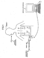
- FIG. 1 is a schematic diagram of an overall configuration of a radio in-vivo information acquiring system according to the present invention.
- the in-vivo information acquiring system uses pantoscopic capsule endoscope as one example of the in-vivo image acquiring apparatus.
- the radio in-vivo information acquiring system includes: a capsule endoscope 3 which is introduced into a body cavity of a subject 1, and picks up body-cavity images so as to transmit data such as an image signal to a receiving apparatus 2 by radio; and the receiving apparatus 2 which is arranged outside the subject 1 and receives body-cavity image data as the image signal radio-transmitted from the capsule endoscope 3.
- the in-vivo information acquiring system further includes a display apparatus 4 that displays the body-cavity images based on the image signal received by the receiving apparatus 2, and the data are transmitted and received between the receiving apparatus 2 and the display apparatus 4 by wired connection or wireless connection between the receiving apparatus 2 and the display apparatus 4.
- the receiving apparatus 2 includes a radio unit 2a having a plurality of receiving antennas A1 to An attached onto an external surface of the body of the subject 1, and a main receiving unit 2b that performs processing on radio signals received via the receiving antennas A1 to An.
- the units 2a and 2b are connected detachably via a connector or the like.
- Each of the receiving antennas A1 to An is attached to a jacket which the subject 1 can wear, and the receiving antennas A1 to An may be attached to the subject 1 when the subject wears the jacket.
- the receiving antennas A1 to An may be detachable from the jacket.
- the display apparatus 4 is for displaying body-cavity images picked up by the capsule endoscope 3, and has a configuration like a workstation that displays images based on the data acquired by the receiving apparatus 2. Specifically, the display apparatus 4 may directly display images on a CRT display, a liquid crystal display, or the like, or may output images to another medium as in a printer.
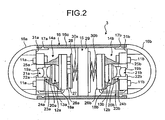
- FIG. 2 is a sectional view of an internal configuration of the capsule endoscope 3.
- the capsule endoscope 3 includes two imaging blocks 14a and 14b that have an illuminating unit, such as LEDs 11a and 11b, as first and second illuminating units that illuminate an interior of the body cavity of the subject 1, and imaging units 13a and 13b that has an imaging element, such as CCDs 12a and 12b, as first and second imagers that pick up images in the body cavity, respectively, as a pair, and a power supply unit 15 that supplies power to the above elements, and the imaging blocks 14a and 14b, and the power supply unit 15 are arranged inside a capsule casing 16.
- an illuminating unit such as LEDs 11a and 11b
- imaging units 13a and 13b that has an imaging element, such as CCDs 12a and 12b, as first and second imagers that pick up images in the body cavity, respectively, as a pair
- a power supply unit 15 that supplies power to the above elements, and the imaging blocks 14a and
- the capsule casing 16 includes transparent end cover casings 16a and 16b of a hemispheric dome shape which cover the imaging blocks 14a and 14b, respectively, and a cylindrical body casing 16c which is engaged with the end cover casings 16a and 16b in a watertight manner via convexo-concave engagement units 17a and 17b, respectively, and in which the imaging blocks 14a and 14b are arranged with the power supply unit 15 placed therebetween.
- the capsule casing 16 is formed in a size swallowable by the subject 1 from the mouth.
- the body casing 16c is formed by a color material through which visible light is not transmitted.
- the imaging units 13a and 13b include CCDs 12a and 12b which are placed on imaging substrates 18a and 18b, respectively, to image ranges illuminated by the illumination light from the LEDs 11a and 11b (imaging visual field ranges), respectively, and imaging lenses 21a and 21b including fixed lenses 19a and 19b and movable lenses 20a and 20b that form subject images on the CCDs 12a and 12b, respectively.
- the fixed lenses 19a and 19b are fixed to fixing frames 22a and 22b, respectively, and the movable lenses 20a and 20b are fixed to movable frames 23a and 23b, respectively, thereby forming focus adjusting units 24a and 24b.
- the LEDs 11a and 11b are placed on illuminating substrates 25a and 25b, respectively, and are arranged on four places near the left, right, top, and bottom sides of a center of a light axis of the imaging lenses 21a and 21b. Further, in the imaging blocks 14a and 14b, control units 26a and 26b that control the respective units in each block are placed on rear surface sides of the imaging substrates 18a and 18b, respectively, and on one control unit 26a of the imaging block 14a, a wireless substrate 28 is arranged. On the wireless substrate 28, a wireless unit 27 including an antenna for radio communication with the outside is mounted.
- the imaging substrates 18a and 18b and the illuminating substrates 25a and 25b are electrically connected by cables, respectively, suitably.
- the power supply unit 15 positioned between the imaging blocks 14a and 14b includes a button type battery 29 having a diameter approximately matching an inner diameter of the body casing 16c.
- a silver oxide battery, a rechargeable battery, a power generating battery or the like may be used.
- spring members 30a and 30b having a torsion-coil-spring-like shape are arranged, respectively, as elastic members which bias the imaging blocks 14a and 14b to the opposing end cover casings 16a and 16b, respectively, i.e., toward the outside.
- the wireless unit 27 on the wireless substrate 28 and the control unit 26b are electrically connected suitably by a cable or the like which passes through the outside of the battery 29.
- the wireless unit 27 may not be shared by the imaging blocks 14a and 14b, and it may be individually provided for each of the imaging blocks 14a and 14b.
- Locating units 31a and 31b which come into contact with portions of the outer periphery sides of the illuminating substrates 25a and 25b so as to locate the imaging blocks 14a and 14b in an axial direction of the capsule endoscope 3, are formed integrally near outer peripheries of the insides of the end cover casings 16a and 16b.
- a rotation preventive locating unit (not shown), which includes a combination of convex and concave portions to be engaged/disengaged with/from each other and locates the imaging blocks 14a and 14b in a circumferential direction around the axis, is formed between the locating units 31a and 31b and the illuminating substrates 25a and 25b.
- FIG. 3 is a schematic block diagram illustrating the internal circuit configuration of the capsule endoscope 3.
- the control unit 26a includes an LED driving circuit 41a and a CCD driving circuit 42a corresponding to the LED 11a and CCD 12a, respectively, and controls the paired LED 11a and CCD 12a that are arranged in the front side (i.e., the left side in FIG. 2 ) of the capsule endoscope 3, for example.
- the control unit 26a has a control circuit 45a which has a timing generator and a synch generator (not shown) for generating various timing signals and synchronous signals.
- the control circuit 45a controls the operations and the operation timing of the driving circuits 41a and 42a based on the timing signals and the synchronous signals generated by the timing generator and the synch generator.
- the control unit 26b has an LED driving circuit 41b and a CCD driving circuit 42b corresponding to the LED 11b and CCD 12b, respectively, and controls the paired LED 11b and CCD 12b that are arranged in the rear side (i.e., the right side in FIG. 2 ) of the capsule endoscope 3, for example.
- the control unit 26b has a control circuit 45b which has a timing generator and a synch generator (not shown) for generating various timing signals and synch signals.
- the control circuit 45b controls the operations and the operation timing of the driving circuits 41b and 42b based on the timing signals and the synch signals generated by the timing generator and the synch generator.
- the control circuits 45a and 45b are in a master-slave relationship such that the control circuit 45a is a master and the control circuit 45b is a slave.
- the control circuit 45b is driven by the control circuit 45a and performs a control operation according to an enable signal EB from the control circuit 45a. For example, the control circuit 45b operates only while the enable signal EB is at a high level.
- the wireless unit 27 includes, as a transmitter provided on an output path of image data picked up by the CCDs 12a and 12b and outputting RF modulated signals, a transmission module 46 and a transmitting antenna 47.
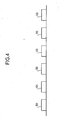
- FIG. 4 is a schematic timing chart of output timing of the image data controlled by the control circuits 45a and 45b.
- B1, B2, and B3 designate image data output from the CCD 12a on the front side in frame unit
- C1, C2, and C3 designate image data output from the CCD 12b on the rear side in frame unit.
- the control circuits 45a and 45b sequentially drive the CCDs 12a and 12b, respectively, in an alternate manner, and control the timing so that illumination timing of the LEDs 11a and 11b is different from output timing of the CCDs 12a and 12b, respectively.
- the LED 11a paired with the CCD 12a is turned on for predetermined time, and after the output operation of the image data from the CCD 12a on the front side is completed, the LED 11b paired with the CCD 12b is turned on for predetermined time so that the output operation of the image data from the CCD 12b on the rear side is performed. Thereafter, such operation control is repeated.
- control circuit 45a turns the LED 11a on for predetermined time via the LED driving circuit 41a according to the timing signals output from the generators, and allows the CCD 12a to image the illuminated portion.
- the control circuit 45a allows the image data B1, B2, and B3 in a frame unit to be output from the CCD 12a to the transmission module 46 via the CCD driving circuit 42a at the timing the LED 11a is turned off.
- the control circuit 45a outputs the enable signal EB (high level) to the control circuit 45b and the transmission module 46, and switches the control into the control by the control circuit 45b.
- the control circuit 45b performs the control operation according to the input of the enable signal EB (high level), and turns the LED 11b on for predetermined time via the LED driving circuit 41b according to the timing signals output from the generators, and allows the CCD 12b to image the illuminated portion.
- the control circuit 45b allows the image data C1, C2, and C3 of frame unit to be output from the CCD 12b to the transmission module 46 via the CCD driving circuit 42b at the timing the LED 11b is turned off.
- the control circuit 45a turns the enable signal EB into a low level at the timing the output operation is completed, and switches the control into the control by the control circuit 45a. Thereafter, the above operation control is repeated.
- the control circuit 45a may turn the enable signal EB into a low level in response to an input of an end signal supplied from the control circuit 45b to the control circuit 45a at the end of output.
- the CCDs 12a and 12b alternately and sequentially output and supply the image data B1, C1, B2, C2, B3, and C3 of frame unit to the transmission module 46, and the image data B1, C1, B2, C2, B3, and C3 are employed as transmission output as RF data.
- the transmission module 46 also has a function as a transmission data generator of the present invention.
- the transmission module 46 generates transmission data by adding identification data, which allows identification of the CCD that picks up image data, to each piece of the image data supplied from the CCDs 12a and 12b according to the level of the enable signal EB supplied from the control circuit 45a, and radio-transmits RF data (radio data) based on the transmission data.
- the image data acquired by the CCD 12a and the image data acquired by the CCD 12b are independent.
- the identification data may be added only to the image data acquired by the CCD 12a, and "zero" (no) identification data may be added to the image data acquired by the CCD 12b.
- actual identification data may be added to each piece of the image data.
- the transmission module 46 determines the image data B1, B2, and B3 input after the input of the enable signal EB of the low level as the image data on the front side picked up by the CCD 12a, and adds identification data representing that the data are picked up by the CCD 12a, e.g., identification data "01" to the image data B1, B2, and B3, and transmits the resulting data.
- the transmission module 46 determines the image data C1, C2, and C3 input after the input of the enable signal EB of the high level as the image data on the rear side picked up by the CCD 12b, and adds identification data representing that the data are picked up by the CCD 12b, e.g., identification data "10" to the image data C1, C2, and C3, and transmits the resulting data.
- the identification data are added to a former tier of the respective image data, and data of white balance coefficient for executing the white balance adjustment, data for the color processing and the like are added to the image data of each CCD.
- the image data B1, C1, B2, C2, B3, and C3 shown in FIG. 4 to which various data including the identification data are added are transmitted from the transmission module 46 in frame unit and at predetermined intervals.
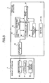
- FIG. 5 is a schematic block diagram of the internal circuit configurations of the receiving apparatus 2 and the display apparatus 4.
- the circuit configurations of the radio unit 2a and the main receiving unit 2b according to the first example are shown as one block in FIG. 5 .
- the receiving apparatus 2 has a reception module 34, and antennas A1 to An, as a receiver.
- the reception module 34 has a function of amplifying and modulating electric wave signals captured by the antennas A1 to An, and is configured as the radio unit 2a.
- the receiving apparatus 2 has a control unit 35 having an identifying unit 36 as an identifying unit, an image processing unit 37 having a function as a compressor, a recording unit 38 which functions as a storage unit and has separate storage areas for each of the CCDs 12a and 12b, and an input/output interface (input/output I/F) 39 having a function as an output unit. These components constitute the main receiving unit 2b.
- the reception module 34 receives the image data transmitted from the capsule endoscope 3 in a frame format via the antennas A1 to An, outputs the identification data of the received frame to the identifying unit 36, and outputs the image data to the image processing unit 37.
- the control unit 35 controls the operations and the operation timing of each component, and supplies electric power to each component.
- the identifying unit 36 determines whether the identification data input from the reception module 34 is the data representing the CCD 12a or the data representing the CCD 12b, and notifies the control unit 35 and the image processing unit 37 of the determined result. Specifically, when the input identification data is "01", the identifying unit 36 determines that the identification data is data representing the CCD 12a, and when the input identification data is "10", the identifying unit 36 determines that the identification data is data representing the CCD 12b, and notifies the control unit 35 and the image processing unit 37 of the determined results.
- the image processing unit 37 determines that the received image data is image data picked up by the CCD 12a, and executes the white balance adjusting process and the color adjusting process on the image data based on the data on the white balance coefficient and the color process added to the image data. Further, the image processing unit 37 performs moving-image compression on the image data, and after raising the compression rate, stores the image data in the storage area for the image data of the CCD 12a in the recording unit 38.
- the image processing unit 37 determines that the received image data is the image data picked up by the CCD 12b, and executes the white balance adjusting process and the color adjusting process on the image data based on the data on the white balance coefficient and the color process added to the image data.
- the image processing unit 37 performs the moving-image compression on the image data, and after raising the compression rate, stores the image data in the storage area for the image data of the CCD 12b in the recording unit 38.
- the recording unit 38 is realized by a hard disc device, for example, and retains various images or the like.
- the recording unit 38 has two divided storage areas.
- the image data picked up by the CCD 12a and the image data picked up by the CCD 12b of the capsule endoscope 3 are stored in the separate storage areas, respectively. Frame numbers and time are added to the image data according to the receiving order of the image data in the receiving apparatus 2.
- the control unit 35 controls the operations and the operation timing of the respective components of the receiving apparatus 2.
- the control unit 35 controls reading of the image data stored in the storage areas of the recording unit 38, and reads the image data of the CCDs 12a and 12b stored in the storage areas.
- the input/output interface 39 is, for example, a USB, which is a serial interface for a personal computer, and outputs the image data of each of the CCDs 12a and 12b read from the recording unit 38 to the display apparatus 4.
- the display apparatus 4 has an input/output interface (input/output I/F) 50 having a function as a capturing unit, a controller 51 having a function as a display controller for controlling display, and a display device 52 that displays the image data.
- the display apparatus 4 has a configuration like a work station or the like such that the controller 51 displays an image on the display device 52 based on data captured by the input/output interface 50.
- the display apparatus 4 may be configured so as to directly display an image on a CRT display, a liquid crystal display, or the like, or to output an image to another medium as a printer.
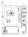
- the display device 52 displays an image display area (window) W on a display screen as shown in one example of the display screen of FIG. 6 .
- the window W is provided with a body-cavity image display area G1 on which a body-cavity image is displayed, a thumbnail image display area G2 on which a thumbnail image Pc is displayed, an identification information display area G3 on which identification information such as an examination ID or a patient ID is displayed, and a time bar G4.
- the thumbnail image display area G2 is provided in an area below the body-cavity image display area G1, the identification information display area G3 is provided to a left side of the body-cavity image display area G1, and the time bar G4 is provided in an area between the body-cavity image display area G1 and the thumbnail image display area G2. Further, a group of buttons for moving-image display control, such as a PLAY button, is provided in an area between the body-cavity image display area G1 and the time bar G4.
- the controller 51 sequentially displays an image Pb based on the image data captured by the input/output interface 50 on the body-cavity image display area G1 at a desired reproduction frame rate (display rate for reproducing an image).
- the controller 51 controls the display so that the images from the CCD 12a captured previously by the input/output interface 50 are sequentially displayed, and then controls the display so that the images from the CCD 12b captured later are sequentially displayed.
- the images from the CCD 12a and the images from the CCD 12b are sequentially displayed on the body-cavity image display area G1 in time division.
- the images from the CCD 12b may be captured firstly or the images from the CC 12a may be captured later.
- the images from the CCD 12b may be displayed firstly.
- first and second imagers acquire the image data of the inside of a subject
- the transmission data generator (transmission module) generates the transmission data by adding the identification data for identifying the CCDs to the image data so as to transmit the transmission data to the receiving apparatus outside the subject.
- the identifying unit determines which CCD has picked up the image data based on the added identification data. Therefore, the receiving side can easily recognize which CCD has picked up the image data.
- the image data are stored separately in the storage areas of the recording unit according to the CCD that is identified by the identifying unit, and the image data of each CCD stored in these storage areas are output to the display apparatus so as to be displayed in time division. Therefore, the image data can be displayed as a series of continuous images on the display apparatus, and a doctor can easily recognize the image.
- the function of an adding unit is provided to the transmission module 46, but the present invention is not limited to this, and the function of the adding unit may be provided to the control units 26a and 26b, for example.
- the imaging blocks 14a and 14b pick up images at the front and rear sides of the advancing direction of the capsule endoscope 3, but the present invention is not limited to this, and the imaging blocks 14a and 14b may be disposed in the capsule endoscope 3 so as to pick up the images on the right and left sides of the advancing direction, for example, or the imaging blocks may be disposed in the capsule endoscope 3 so that the direction of the light axis (imaging direction) of the imaging blocks 14a and 14b is not parallel but diagonal with respect to the axis of the capsule endoscope 3.
- the image data picked up by the CCDs 12a and 12b are individually transmitted to the receiving apparatus, but the present invention is not limited to this, and as shown in FIG. 7 , for example, the image data in the front and the rear directions of the capsule endoscope 3 picked up by the CCDs 12a and 12b can be transmitted as an image data pair.
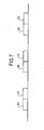
- FIG. 7 is a schematic timing chart of one example of the transmission timing of the transmission module 46.
- two pieces of image data are combined as an image data pair having a frame format and transmitted from the transmission module 46.
- two pieces of image data picked up respectively by the CCDs 12a and 12b at closest imaging times e.g., the image data B1 and C1, the image data B2 and C2, and the image data B3 and C3 are transmitted as the image data pair.
- the identification data may be added in front of each of the image data so that each piece of the simultaneously transmitted image data can be identified whether it is picked up by the CCD 12a or the CCD 12b.
- the receiving apparatus 2 may store each of the received image data pair B1 and C1, the image data pair B2 and C2, and the image data pair B3 and C3 in the recording unit 38 as a pair, or alternatively, the receiving apparatus 2 may store the image data separately depending on which of the CCDs 12a and 12b picks up the same, similarly to the first example. Still alternatively, the display apparatus 4 may sequentially display images based on the image data pair B1 and C1, the image data pair B2 and C2, and the image data pair B3 and C3 so that the images corresponding to two pieces of image data included in each image data pair is displayed simultaneously, or alternatively, the display apparatus 4 may sequentially display images in time division, similarly to the first example.
- the two pieces of image data which are picked up by different CCDs at closest imaging times are combined as an image data pair and transmitted in one frame. Therefore, intermission between the frame transmission decreases and the time required for transmitting the entire image data can be reduced, in comparison with the first example in which each piece of image data is transmitted as a separate frame
- the recording and the display of the received image data can be performed based on the image data pair or based on each piece of the image data, whereby general versatility of the apparatus and the system can be enhanced with respect to the image recording and the image observation.
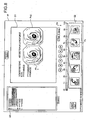
- FIG. 8 is a diagram of another example of the display screen of the display device 52 shown in FIG. 5 .
- a difference of the display device according to the third example from the display device 52 in the first example is that an image Pb1 picked up by the CCD 12a and an image Pb2 picked up by the CCD 12b are displayed simultaneously on the body-cavity image display area G1.
- the receiving time at which the receiving apparatus 2 receives the image data is added to the image data and output, and the display apparatus 4 simultaneously displays the images Pb1 and Pb2 whose receiving times are the closest as a pair of images in the body-cavity image display area G1.
- the controller 51 analyzes the receiving time and controls the display so that the images Pb1 and Pb2 are displayed simultaneously in the body-cavity image display area G1 based on the image data B1 and C1, the image data B2 and C2, and the image data B3 and C3.
- the third example since the images picked up by the different CCDs can be simultaneously displayed on the display device, the general versatility of the apparatus and the system with respect to the image observation can be further enhanced.
- the manner of display according to the third example can be applied to a display where a pair of images is displayed simultaneously as in the second example.
- the controller 51 of the display apparatus 4 determines whether the image picked up by one of the CCDs 12a and 12b is a front-side image or a rear-side image of the capsule endoscope 3 based on an image captured by the input/output interface 50.
- the controller 51 having a function as a direction detector, estimates whether the acquired image is a front-side image or a rear-side image of the capsule endoscope 3 based on a motion vector. In the direction estimation based on the motion vector, a conventional template matching is utilized.
- a master image (template) in a certain frame f(t) is superimposed on an image in a next frame f (t+1), and a portion in the frame f (t+1) whose pixel value is the closest to that in the frame f(t) is detected.
- the template is searched from the frame f(t+1) so that a motion vector is obtained.
- the motion vector is obtained for each continuous image of the CCD 12a or the CCD 12b.
- the controller 51 obtains a cumulative total value of the directions of the motion vectors obtained for the respective continuous image, and for example, detects whether the cumulative total value directs outward from the center portion of the entire image or directs the center portion from the outer direction of the entire image.
- the continuous image is determined as a group of front-side images of the capsule endoscope 3, and when the cumulative total value directs the center portion, the continuous image is determined as a group of rear-side images of the capsule endoscope 3.
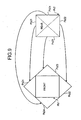
- each of the images Pb2 is divided into four rectangular images Pb21 to Pb24 by dotted diagonal lines. Further, the controller 51 controls the display so that the front-side images Pb1 of the capsule endoscope 3 picked up by the CCD 12a are sequentially displayed on the body-cavity image display area G1, and the images Pb21 to Pb24 obtained by dividing the image Pb2 whose receiving time is the closest to that of the image Pb1 are superimposed on four sides of the image Pb1 so as to be sequentially displayed. As a result, in the display apparatus 4, the front-side images are displayed stereoscopically and appear as if the images flow to the rear direction.
- the left, right, top, and bottom directions of the CCDs 12a and 12b are defined by a two-dimensional scanning direction of an imaging surface (for example, the scanning from left to right is repeated in a top-bottom direction), and there can be different combinations of the image in the front direction of the capsule endoscope 3 and the divided images in the rear direction varies depending on the difference in the two-dimensional scanning direction.
- the CCD 12a performs the two-dimensional scanning repeatedly from the right to the left in a downward direction while the CCD 12b performs the two-dimensional scanning repeatedly from the left to the right in a downward direction.
- the image is the front-side image or the rear-side image of the capsule endoscope, and the front-side image and the rear-side image are displayed by the display apparatus.
- the image data in the front and rear directions from the capsule endoscope can be displayed recognizably.
- the divided rear-side images are superimposed on the periphery of the front-side image so as to be displayed on the display area of the display apparatus. Therefore, the images picked up by the CCDs can be displayed so as to appear stereoscopically, and thus the in-vivo information acquiring system with enhanced general versatility can be provided.
- the in-vivo image acquiring apparatus, the receiving apparatus, and the in-vivo information acquiring system of the present invention are useful when images of the insides of organs of a subject such as a patient are picked up by an imaging device in a wide range. Particularly, they are suitable for the in-vivo image acquiring apparatus, the receiving apparatus, and the in-vivo information acquiring system, which allow for the identification of an image in a group of intra-organ images picked up by plural imaging devices, based on the imaging device.
Description
- The present invention relates to an in-vivo image acquiring apparatus such as a pantoscopic capsule endoscope, a receiving apparatus that receives image data or the like from the in-vivo image acquiring apparatus, and an in-vivo information acquiring system using them.
- In recent years, capsule endoscopes which are provided with an imaging function and a radio communicating function have appeared in the field of endoscopes. After the capsule endoscope is swallowed by an examinee as a subject from the mouth for observation (examination) and until naturally discharged from a living body (human body) of the examinee, the capsule endoscope moves through insides of organs such as esophagus, stomach, and small intestine (the inside of a body cavity) according to their peristaltic motions, and sequentially picks up images at a predetermined imaging rate using the imaging function.
- Image data, which are picked up in the body cavity by the capsule endoscope during the observation period in which the capsule endoscope is moving through the inside of the organs, are sequentially transmitted to the outside of the subject by the radio communicating function, and are accumulated in a memory provided in an external receiver. After the observation, doctors or nurses can make the images of the body cavity displayed on a display unit such as a display based on the image data accumulated in the memory of the receiver to make diagnosis (see Patent Document 1).
- Patent Document 1: Japanese Patent Application Laid-Open No.
2003-19111 - Patent Document 2:
US Patent Application Laid-Open No. 2004/199061 -
DE 10323216 describes an endoscopic device in capsule form for imaging body cavities, comprising two cameras having a common optical axis and oriented in opposite directions. Both cameras may share a single transmitter and a single battery. The transmitter may identify the camera associated with a transmitted image by transmitting the images during alternating time periods according to a timing schedule previously determined and known to the receiving apparatus; sending data corresponding to each camera at differing frequencies; marking pixels of the images by outputting black pixels at a predetermined location for each camera; changing a color temperature of a camera; or imaging a marker disposed on the transparent capsule casing disposed over the camera or on a camera lens. -
US 2004/199061 describes an in-vivo imaging device including at least one illumination source, at least one image sensor, and at least two optical systems disposed on one side of the device such that the imaging devices have overlapping imaging regions. At a beginning of each imaging cycle, a controller switches on a first light switching unit and turns off a second light switching unit to allow light focused by a first imaging unit to be projected onto the image sensor, and to prevent light from a second imaging unit from being projected onto the image sensor. After imaging from the first imaging unit, the first light switching unit is switched off and the second light switching unit is switched off, and the second imaging device transmits light to the image sensor. When image data is transmitted, both light switching units are switched off. -
US 2005/049462 describes a capsule device having a battery disposed in the capsule, a cathode portion on a first side of the battery, and a spring-like anode portion on a second side of the battery. -
WO 2002/080376 describes an imaging device having an image sensor and at least one illumination source, wherein the illumination source is controlled by a controller to illuminate for a first period and to be off for a second period. Image data may be transmitted during a period when the illumination source is shut off. -
JP 2005/143991 claim 1. - Generally, the capsule endoscopes as described above are monocular capsule endoscopes which only pick up images of body cavity located in its advancing direction, i.e., at its front side, but in recent years, a pantoscopic capsule endoscope which picks up images on the front and rear sides of the advancing direction is proposed in order to enlarge a visual field at the time of observing esophagus or the like (see Patent Document 2). In the pantoscopic capsule endoscope, a plurality of imaging blocks are provided to the front and rear sides of a capsule casing so as to pick up images on the front and rear sides of an advancing direction of the capsule casing in the body cavity. Each of the imaging blocks has a pair of an illuminating unit such as LED which illuminates the inside of a body cavity and an imaging device such as CCD which picks up an image of the inside of the illuminated body cavity.
- However,
Patent Document 2 and others merely describe that the pantoscopic capsule endoscope has the plurality of imaging devices that pick up images in the front and rear directions, and does not describe transmission control for transmitting the image data and display control at the time of displaying the images. As a result, the advantage of the pantoscopic capsule endoscope is not effectively utilized. - The present invention is made in view of the above, and an object of the present invention is to provide an in-vivo information acquiring system which enable a receiving side to easily recognize which of imaging elements has picked up received image data.
- Further, another object of the present invention is to display an image in such a manner that it can be recognized in which direction of the in-vivo image acquiring apparatus the image is picked up.
- To solve the problems as described above and to achieve an object, an in-vivo image acquiring system according to
claim 1 is provided. The in-vivo image acquiring system includes a first imager that serves to acquire image data, a second imager that serves to acquire image data which is formed independent of the image data acquired by the first imager, and a transmission data generator that generates transmission data by receiving the image data from the first and the second imagers and adding identification data, which allows for identification of the imager, to each piece of the image data. - Further, the in-vivo image acquiring apparatus preferably further includes a first illuminating unit that illuminates an imaging visual field of the first imager, a second illuminating unit that illuminates an imaging visual field of the second imager, and a control unit that controls driving timing of each of the first imager, the first illuminating unit, the second imager, and the second illuminating unit, wherein the control unit controls so that the image data acquired by the first imager is supplied to the transmission data generator while the first illuminating unit is turned off, whereas the image data acquired by the second imager is supplied to the transmission data generator while the second illuminating unit is turned off.
- Further, in an in-vivo image acquiring apparatus the control unit controls so that, after the image data acquired by the first imager is supplied to the transmission data generator, the second illuminating unit is turned on and the second imager picks up an image, and thereafter the second illuminating unit is turned off, and the control unit controls so that, after the image data acquired by the second imager is supplied to the transmission data generator, the first illuminating unit is turned on and the first imager picks up an image, and thereafter the first illuminating unit is turned off.
- An in-vivo image acquiring apparatus may further include a capsule casing that is formed with end cover casings engaged respectively with two ends of a body casing, and a spring member that is in contact with a battery arranged inside the capsule casing, that is compressed when the body casing and the end cover casings are engaged, and that has a biasing force directed towards the end cover casings.
- Further, a receiving apparatus may include a receiver that receives image data to which identification data is added, an identifying unit that identifies which imager picks up the image data received by the receiver based on the identification data added, and a storage unit that has divided storage areas and stores the image data in the storage areas according to the imagers identified by the identifying unit.
- A receiving apparatus may further include a compressor that performs moving-image compression separately on the image data among the image data received by the receiver according to the imager which is identified by the identifying unit.
- Further, the receiving apparatus according to the present invention further includes an output unit that sequentially outputs the image data stored in the storage unit for each imager.
- The in-vivo information acquiring system according to the present invention includes an in-vivo image acquiring apparatus that includes a first imager that serves to acquire image data, a second imager that serves to acquire image data which is formed independent of the image data acquired by the first imager, a transmission data generator that generates transmission data by receiving the image data from the first and the second imagers and adding identification data, which allows for identification of the imager, to each piece of the image data, and a transmitter that performs radio transmission based on the transmission data generated by the transmission data generator, and a receiving apparatus that includes a receiver that receives data transmitted by the transmitter, an identifying unit that identifies which imager picks up image data included in the data received by the receiver based on the identification data added, and a storage unit that has divided storage areas and stores the image data in the storage areas according to the imagers identified by the identifying unit.
- Further, in the in-vivo information acquiring system according to the present invention, the transmitter transmits image data picked up by plural imagers as an image data pair.
- Further, in an in-vivo information acquiring system the receiving apparatus further may include a compressor that performs moving-image compression separately on the image data among the image data received by the receiver according to the imager which is identified by the identifying unit.
- Further, in the in-vivo information acquiring system according to the present invention, the receiving apparatus further includes an output unit that sequentially outputs the image data stored in the storage unit for each imagers, and the in-vivo information acquiring system further includes an image display apparatus that includes a capturing unit which captures the image data sequentially output by the output unit, and a display controller that controls display so that the image data captured by the capturing unit is displayed in separate display areas according to the imager.
- Further, in the in-vivo information acquiring system according to the present invention, the image display apparatus further includes a direction detector that finds a motion vector of each image sequence, and detects in which direction of the in-vivo image acquiring apparatus the image sequentially acquired from the receiving apparatus is picked up inside a body cavity, based on the motion vector.
- Further, in an in-vivo information acquiring system the in-vivo image acquiring apparatus preferably includes a capsule casing that is formed with end cover casings engaged respectively with two ends of a body casing, and a spring member that is in contact with a battery arranged inside the capsule casing, that is compressed when the body casing and the end cover casings are engaged, and that has a biasing force directed towards the end cover casings.
- The in-vivo image acquiring apparatus according to the present invention receives the image data from the first imager and the second imager and generates the transmission data in the transmission data generator by adding the identification data to allow for an identification of the imagers, whereby the in-vivo image acquiring apparatus is advantageous in that, when the receiving apparatus outside the subject receives the transmission data, the receiving side can easily recognize which of the imagers picks up the received image data.
-
-
FIG. 1 is a system conceptual diagram illustrating how an in-vivo information acquiring system according to the present invention is configured; -
FIG. 2 is a sectional view of an internal configuration of a capsule endoscope; -
FIG. 3 is a schematic block diagram of an internal circuit configuration of the capsule endoscope; -
FIG. 4 is a schematic timing chart of one example of output timing of image data controlled by a control circuit shown inFIG. 3 ; -
FIG. 5 is a schematic block diagram of internal circuit configurations of a receiving apparatus and a display apparatus; -
FIG. 6 is a diagram of one example of a display screen of the display apparatus shown inFIG. 5 ; -
FIG. 7 is a schematic timing chart of one example of transmission timing of the image data; -
FIG. 8 is a diagram of another example of the display screen of the display apparatus shown inFIG. 5 ; and -
FIG. 9 is a diagram of one example of an image displayed on the display screen of the display apparatus. -
- 1
- Subject
- 2
- Receiving apparatus
- 2a
- Radio unit
- 2b
- Main receiving unit
- 3
- Capsule endoscope
- 4
- Display apparatus
- 11a, 11b
- LED
- 12a, 12b
- CCD
- 13a, 13b
- Imaging unit
- 14a, 14b
- Imaging block
- 15
- Power supply unit
- 16
- Capsule casing
- 16a,
- 16b Cover casing
- 16c
- Body casing
- 17a, 17b
- Convex-concave engagement unit
- 18a, 18b
- Imaging substrate
- 19a, 19b
- Fixed lens
- 20a, 20b
- Movable lens
- 21a, 21b
- Imaging lens
- 22a, 22b
- Fixing frame
- 23a, 23b
- Movable frame
- 24a, 24b
- Focus adjusting unit
- 25a, 25b
- Illuminating substrate
- 26a, 26b, 35
- Control unit
- 27
- Wireless unit
- 28
- Wireless substrate
- 29
- Battery
- 30a, 30b
- Spring member
- 31a, 31b
- Locating unit
- 34
- Reception module
- 36
- Identifying unit
- 37
- Image processing unit
- 38
- Recording unit
- 39, 50
- Input/output interface (input/output I/F)
- 41a, 41b
- LED driving circuit
- 42a, 42b
- CCD driving circuit
- 45a, 45b
- Control circuit
- 46
- Transmission module
- 47
- Transmitting antenna
- 51
- Controller
- 52
- Display device
- A1 to An
- Receiving antenna
- Examples of an in-vivo image acquiring apparatus, a receiving apparatus, and an in-vivo information acquiring system useful for understanding the present invention are explained in detail below with reference to
FIGS. 1 to 9 . The present invention is not limited to these examples, and can be variously changed without departing from the scope of the present invention. -
FIG. 1 is a schematic diagram of an overall configuration of a radio in-vivo information acquiring system according to the present invention. The in-vivo information acquiring system uses pantoscopic capsule endoscope as one example of the in-vivo image acquiring apparatus. InFIG. 1 , the radio in-vivo information acquiring system includes: acapsule endoscope 3 which is introduced into a body cavity of a subject 1, and picks up body-cavity images so as to transmit data such as an image signal to a receivingapparatus 2 by radio; and the receivingapparatus 2 which is arranged outside thesubject 1 and receives body-cavity image data as the image signal radio-transmitted from thecapsule endoscope 3. The in-vivo information acquiring system further includes adisplay apparatus 4 that displays the body-cavity images based on the image signal received by the receivingapparatus 2, and the data are transmitted and received between the receivingapparatus 2 and thedisplay apparatus 4 by wired connection or wireless connection between the receivingapparatus 2 and thedisplay apparatus 4. - The receiving
apparatus 2 includes aradio unit 2a having a plurality of receiving antennas A1 to An attached onto an external surface of the body of the subject 1, and amain receiving unit 2b that performs processing on radio signals received via the receiving antennas A1 to An. Theunits subject 1 can wear, and the receiving antennas A1 to An may be attached to the subject 1 when the subject wears the jacket. The receiving antennas A1 to An may be detachable from the jacket. - The
display apparatus 4 is for displaying body-cavity images picked up by thecapsule endoscope 3, and has a configuration like a workstation that displays images based on the data acquired by the receivingapparatus 2. Specifically, thedisplay apparatus 4 may directly display images on a CRT display, a liquid crystal display, or the like, or may output images to another medium as in a printer. - The
capsule endoscope 3 is explained with reference toFIG. 2. FIG. 2 is a sectional view of an internal configuration of thecapsule endoscope 3. Thecapsule endoscope 3 includes twoimaging blocks LEDs imaging units 13a and 13b that has an imaging element, such asCCDs power supply unit 15 that supplies power to the above elements, and the imaging blocks 14a and 14b, and thepower supply unit 15 are arranged inside acapsule casing 16. - The
capsule casing 16 includes transparentend cover casings cylindrical body casing 16c which is engaged with theend cover casings concave engagement units power supply unit 15 placed therebetween. Thecapsule casing 16 is formed in a size swallowable by the subject 1 from the mouth. Thebody casing 16c is formed by a color material through which visible light is not transmitted. - The
imaging units 13a and 13b includeCCDs imaging substrates LEDs imaging lenses lenses movable lenses 20a and 20b that form subject images on theCCDs lenses frames movable lenses 20a and 20b are fixed tomovable frames 23a and 23b, respectively, thereby formingfocus adjusting units - The
LEDs substrates imaging lenses control units imaging substrates control unit 26a of theimaging block 14a, awireless substrate 28 is arranged. On thewireless substrate 28, awireless unit 27 including an antenna for radio communication with the outside is mounted. Theimaging substrates substrates - The
power supply unit 15 positioned between the imaging blocks 14a and 14b includes abutton type battery 29 having a diameter approximately matching an inner diameter of thebody casing 16c. As thebattery 29, a silver oxide battery, a rechargeable battery, a power generating battery or the like may be used. At central portions between the imaging blocks 14a and 14b and thebattery 29,spring members end cover casings wireless unit 27 on thewireless substrate 28 and thecontrol unit 26b are electrically connected suitably by a cable or the like which passes through the outside of thebattery 29. Thewireless unit 27 may not be shared by the imaging blocks 14a and 14b, and it may be individually provided for each of the imaging blocks 14a and 14b. - Locating
units substrates capsule endoscope 3, are formed integrally near outer peripheries of the insides of theend cover casings units substrates - An internal circuit configuration of the
capsule endoscope 3 is explained below with reference toFIG. 3. FIG. 3 is a schematic block diagram illustrating the internal circuit configuration of thecapsule endoscope 3. InFIG. 3 , thecontrol unit 26a includes anLED driving circuit 41a and aCCD driving circuit 42a corresponding to theLED 11a andCCD 12a, respectively, and controls the pairedLED 11a andCCD 12a that are arranged in the front side (i.e., the left side inFIG. 2 ) of thecapsule endoscope 3, for example. Further, thecontrol unit 26a has acontrol circuit 45a which has a timing generator and a synch generator (not shown) for generating various timing signals and synchronous signals. Thecontrol circuit 45a controls the operations and the operation timing of the drivingcircuits - The
control unit 26b has anLED driving circuit 41b and aCCD driving circuit 42b corresponding to theLED 11b andCCD 12b, respectively, and controls the pairedLED 11b andCCD 12b that are arranged in the rear side (i.e., the right side inFIG. 2 ) of thecapsule endoscope 3, for example. Thecontrol unit 26b has acontrol circuit 45b which has a timing generator and a synch generator (not shown) for generating various timing signals and synch signals. Thecontrol circuit 45b controls the operations and the operation timing of the drivingcircuits - The
control circuits control circuit 45a is a master and thecontrol circuit 45b is a slave. Thecontrol circuit 45b is driven by thecontrol circuit 45a and performs a control operation according to an enable signal EB from thecontrol circuit 45a. For example, thecontrol circuit 45b operates only while the enable signal EB is at a high level. - The
wireless unit 27 includes, as a transmitter provided on an output path of image data picked up by theCCDs transmission module 46 and a transmittingantenna 47. -
FIG. 4 is a schematic timing chart of output timing of the image data controlled by thecontrol circuits FIG. 4 , B1, B2, and B3 designate image data output from theCCD 12a on the front side in frame unit, and C1, C2, and C3 designate image data output from theCCD 12b on the rear side in frame unit. Thecontrol circuits CCDs LEDs CCDs LED 11a paired with theCCD 12a is turned on for predetermined time, and after the output operation of the image data from theCCD 12a on the front side is completed, theLED 11b paired with theCCD 12b is turned on for predetermined time so that the output operation of the image data from theCCD 12b on the rear side is performed. Thereafter, such operation control is repeated. - More specifically, the
control circuit 45a turns theLED 11a on for predetermined time via theLED driving circuit 41a according to the timing signals output from the generators, and allows theCCD 12a to image the illuminated portion. Thecontrol circuit 45a allows the image data B1, B2, and B3 in a frame unit to be output from theCCD 12a to thetransmission module 46 via theCCD driving circuit 42a at the timing theLED 11a is turned off. When the output operation is completed, thecontrol circuit 45a outputs the enable signal EB (high level) to thecontrol circuit 45b and thetransmission module 46, and switches the control into the control by thecontrol circuit 45b. - The
control circuit 45b performs the control operation according to the input of the enable signal EB (high level), and turns theLED 11b on for predetermined time via theLED driving circuit 41b according to the timing signals output from the generators, and allows theCCD 12b to image the illuminated portion. Thecontrol circuit 45b allows the image data C1, C2, and C3 of frame unit to be output from theCCD 12b to thetransmission module 46 via theCCD driving circuit 42b at the timing theLED 11b is turned off. Thecontrol circuit 45a turns the enable signal EB into a low level at the timing the output operation is completed, and switches the control into the control by thecontrol circuit 45a. Thereafter, the above operation control is repeated. Alternatively, in this circuit configuration, thecontrol circuit 45a may turn the enable signal EB into a low level in response to an input of an end signal supplied from thecontrol circuit 45b to thecontrol circuit 45a at the end of output. - Through the above operation, the
CCDs transmission module 46, and the image data B1, C1, B2, C2, B3, and C3 are employed as transmission output as RF data. Thetransmission module 46 also has a function as a transmission data generator of the present invention. Thetransmission module 46 generates transmission data by adding identification data, which allows identification of the CCD that picks up image data, to each piece of the image data supplied from theCCDs control circuit 45a, and radio-transmits RF data (radio data) based on the transmission data. In the first example, the image data acquired by theCCD 12a and the image data acquired by theCCD 12b are independent. Alternatively, the identification data may be added only to the image data acquired by theCCD 12a, and "zero" (no) identification data may be added to the image data acquired by theCCD 12b. Still alternatively, actual identification data may be added to each piece of the image data. - Specifically, the
transmission module 46 determines the image data B1, B2, and B3 input after the input of the enable signal EB of the low level as the image data on the front side picked up by theCCD 12a, and adds identification data representing that the data are picked up by theCCD 12a, e.g., identification data "01" to the image data B1, B2, and B3, and transmits the resulting data. Further, thetransmission module 46 determines the image data C1, C2, and C3 input after the input of the enable signal EB of the high level as the image data on the rear side picked up by theCCD 12b, and adds identification data representing that the data are picked up by theCCD 12b, e.g., identification data "10" to the image data C1, C2, and C3, and transmits the resulting data. In the frame, the identification data are added to a former tier of the respective image data, and data of white balance coefficient for executing the white balance adjustment, data for the color processing and the like are added to the image data of each CCD. The image data B1, C1, B2, C2, B3, and C3 shown inFIG. 4 to which various data including the identification data are added are transmitted from thetransmission module 46 in frame unit and at predetermined intervals. - Internal circuit configurations of the receiving
apparatus 2 and thedisplay apparatus 4 are explained below.FIG. 5 is a schematic block diagram of the internal circuit configurations of the receivingapparatus 2 and thedisplay apparatus 4. The circuit configurations of theradio unit 2a and themain receiving unit 2b according to the first example are shown as one block inFIG. 5 . The receivingapparatus 2 has areception module 34, and antennas A1 to An, as a receiver. Thereception module 34 has a function of amplifying and modulating electric wave signals captured by the antennas A1 to An, and is configured as theradio unit 2a. - The receiving
apparatus 2 has acontrol unit 35 having an identifyingunit 36 as an identifying unit, animage processing unit 37 having a function as a compressor, arecording unit 38 which functions as a storage unit and has separate storage areas for each of theCCDs main receiving unit 2b. - The
reception module 34 receives the image data transmitted from thecapsule endoscope 3 in a frame format via the antennas A1 to An, outputs the identification data of the received frame to the identifyingunit 36, and outputs the image data to theimage processing unit 37. - The
control unit 35 controls the operations and the operation timing of each component, and supplies electric power to each component. The identifyingunit 36 determines whether the identification data input from thereception module 34 is the data representing theCCD 12a or the data representing theCCD 12b, and notifies thecontrol unit 35 and theimage processing unit 37 of the determined result. Specifically, when the input identification data is "01", the identifyingunit 36 determines that the identification data is data representing theCCD 12a, and when the input identification data is "10", the identifyingunit 36 determines that the identification data is data representing theCCD 12b, and notifies thecontrol unit 35 and theimage processing unit 37 of the determined results. - When the determined result in the identifying
unit 36 indicates theCCD 12a, theimage processing unit 37 determines that the received image data is image data picked up by theCCD 12a, and executes the white balance adjusting process and the color adjusting process on the image data based on the data on the white balance coefficient and the color process added to the image data. Further, theimage processing unit 37 performs moving-image compression on the image data, and after raising the compression rate, stores the image data in the storage area for the image data of theCCD 12a in therecording unit 38. - When the determined result in the identifying
unit 36 indicates theCCD 12b, theimage processing unit 37 determines that the received image data is the image data picked up by theCCD 12b, and executes the white balance adjusting process and the color adjusting process on the image data based on the data on the white balance coefficient and the color process added to the image data. Theimage processing unit 37 performs the moving-image compression on the image data, and after raising the compression rate, stores the image data in the storage area for the image data of theCCD 12b in therecording unit 38. - The
recording unit 38 is realized by a hard disc device, for example, and retains various images or the like. For example, therecording unit 38 has two divided storage areas. The image data picked up by theCCD 12a and the image data picked up by theCCD 12b of thecapsule endoscope 3 are stored in the separate storage areas, respectively. Frame numbers and time are added to the image data according to the receiving order of the image data in the receivingapparatus 2. - The
control unit 35 controls the operations and the operation timing of the respective components of the receivingapparatus 2. Thecontrol unit 35 controls reading of the image data stored in the storage areas of therecording unit 38, and reads the image data of theCCDs - The input/
output interface 39 is, for example, a USB, which is a serial interface for a personal computer, and outputs the image data of each of theCCDs recording unit 38 to thedisplay apparatus 4. - The
display apparatus 4 has an input/output interface (input/output I/F) 50 having a function as a capturing unit, a controller 51 having a function as a display controller for controlling display, and adisplay device 52 that displays the image data. Thedisplay apparatus 4 has a configuration like a work station or the like such that the controller 51 displays an image on thedisplay device 52 based on data captured by the input/output interface 50. Specifically, thedisplay apparatus 4 may be configured so as to directly display an image on a CRT display, a liquid crystal display, or the like, or to output an image to another medium as a printer. - The
display device 52 displays an image display area (window) W on a display screen as shown in one example of the display screen ofFIG. 6 . The window W is provided with a body-cavity image display area G1 on which a body-cavity image is displayed, a thumbnail image display area G2 on which a thumbnail image Pc is displayed, an identification information display area G3 on which identification information such as an examination ID or a patient ID is displayed, and a time bar G4. The thumbnail image display area G2 is provided in an area below the body-cavity image display area G1, the identification information display area G3 is provided to a left side of the body-cavity image display area G1, and the time bar G4 is provided in an area between the body-cavity image display area G1 and the thumbnail image display area G2. Further, a group of buttons for moving-image display control, such as a PLAY button, is provided in an area between the body-cavity image display area G1 and the time bar G4. - The controller 51 sequentially displays an image Pb based on the image data captured by the input/
output interface 50 on the body-cavity image display area G1 at a desired reproduction frame rate (display rate for reproducing an image). When the image is displayed, the controller 51 controls the display so that the images from theCCD 12a captured previously by the input/output interface 50 are sequentially displayed, and then controls the display so that the images from theCCD 12b captured later are sequentially displayed. As a result, the images from theCCD 12a and the images from theCCD 12b are sequentially displayed on the body-cavity image display area G1 in time division. As to the order in which the image data are captured by the input/output interface 50, the images from theCCD 12b may be captured firstly or the images from theCC 12a may be captured later. As to the display order, the images from theCCD 12b may be displayed firstly. - In the first example, first and second imagers (plural CCDs) acquire the image data of the inside of a subject, and the transmission data generator (transmission module) generates the transmission data by adding the identification data for identifying the CCDs to the image data so as to transmit the transmission data to the receiving apparatus outside the subject. When the image data, to which the identification data for identifying the CCD which has performed the imaging are added, are transmitted and the receiving apparatus outside the subject receives the image data, the identifying unit determines which CCD has picked up the image data based on the added identification data. Therefore, the receiving side can easily recognize which CCD has picked up the image data.
- In the first embodiment, the image data are stored separately in the storage areas of the recording unit according to the CCD that is identified by the identifying unit, and the image data of each CCD stored in these storage areas are output to the display apparatus so as to be displayed in time division. Therefore, the image data can be displayed as a series of continuous images on the display apparatus, and a doctor can easily recognize the image.
- In the first example, the function of an adding unit is provided to the
transmission module 46, but the present invention is not limited to this, and the function of the adding unit may be provided to thecontrol units capsule endoscope 3, but the present invention is not limited to this, and the imaging blocks 14a and 14b may be disposed in thecapsule endoscope 3 so as to pick up the images on the right and left sides of the advancing direction, for example, or the imaging blocks may be disposed in thecapsule endoscope 3 so that the direction of the light axis (imaging direction) of the imaging blocks 14a and 14b is not parallel but diagonal with respect to the axis of thecapsule endoscope 3. - In the first example, the image data picked up by the
CCDs FIG. 7 , for example, the image data in the front and the rear directions of thecapsule endoscope 3 picked up by theCCDs FIG. 7 is a schematic timing chart of one example of the transmission timing of thetransmission module 46. In the second example, two pieces of image data are combined as an image data pair having a frame format and transmitted from thetransmission module 46. For example, two pieces of image data picked up respectively by theCCDs CCD 12a or theCCD 12b. - The receiving
apparatus 2 may store each of the received image data pair B1 and C1, the image data pair B2 and C2, and the image data pair B3 and C3 in therecording unit 38 as a pair, or alternatively, the receivingapparatus 2 may store the image data separately depending on which of theCCDs display apparatus 4 may sequentially display images based on the image data pair B1 and C1, the image data pair B2 and C2, and the image data pair B3 and C3 so that the images corresponding to two pieces of image data included in each image data pair is displayed simultaneously, or alternatively, thedisplay apparatus 4 may sequentially display images in time division, similarly to the first example. - In the second example, the two pieces of image data which are picked up by different CCDs at closest imaging times are combined as an image data pair and transmitted in one frame. Therefore, intermission between the frame transmission decreases and the time required for transmitting the entire image data can be reduced, in comparison with the first example in which each piece of image data is transmitted as a separate frame
- Further, in the second example, the recording and the display of the received image data can be performed based on the image data pair or based on each piece of the image data, whereby general versatility of the apparatus and the system can be enhanced with respect to the image recording and the image observation.
-
FIG. 8 is a diagram of another example of the display screen of thedisplay device 52 shown inFIG. 5 . A difference of the display device according to the third example from thedisplay device 52 in the first example is that an image Pb1 picked up by theCCD 12a and an image Pb2 picked up by theCCD 12b are displayed simultaneously on the body-cavity image display area G1. - In the third example, the receiving time at which the receiving
apparatus 2 receives the image data is added to the image data and output, and thedisplay apparatus 4 simultaneously displays the images Pb1 and Pb2 whose receiving times are the closest as a pair of images in the body-cavity image display area G1. Specifically, in thedisplay apparatus 4, the controller 51 analyzes the receiving time and controls the display so that the images Pb1 and Pb2 are displayed simultaneously in the body-cavity image display area G1 based on the image data B1 and C1, the image data B2 and C2, and the image data B3 and C3. - In the third example, since the images picked up by the different CCDs can be simultaneously displayed on the display device, the general versatility of the apparatus and the system with respect to the image observation can be further enhanced. The manner of display according to the third example can be applied to a display where a pair of images is displayed simultaneously as in the second example.
- In an embodiment of the invention, the controller 51 of the
display apparatus 4 determines whether the image picked up by one of theCCDs capsule endoscope 3 based on an image captured by the input/output interface 50. The controller 51, having a function as a direction detector, estimates whether the acquired image is a front-side image or a rear-side image of thecapsule endoscope 3 based on a motion vector. In the direction estimation based on the motion vector, a conventional template matching is utilized. - Specifically, a master image (template) in a certain frame f(t) is superimposed on an image in a next frame f (t+1), and a portion in the frame f (t+1) whose pixel value is the closest to that in the frame f(t) is detected. As a result, the template is searched from the frame f(t+1) so that a motion vector is obtained. The motion vector is obtained for each continuous image of the
CCD 12a or theCCD 12b. - The controller 51 obtains a cumulative total value of the directions of the motion vectors obtained for the respective continuous image, and for example, detects whether the cumulative total value directs outward from the center portion of the entire image or directs the center portion from the outer direction of the entire image. When the cumulative total value directs outward, the continuous image is determined as a group of front-side images of the
capsule endoscope 3, and when the cumulative total value directs the center portion, the continuous image is determined as a group of rear-side images of thecapsule endoscope 3. - When the controller 51 determines that the respective images Pb2 picked up by the
CCD 12b are the rear-side image group of thecapsule endoscope 3, as shown inFIG. 9 , each of the images Pb2 is divided into four rectangular images Pb21 to Pb24 by dotted diagonal lines. Further, the controller 51 controls the display so that the front-side images Pb1 of thecapsule endoscope 3 picked up by theCCD 12a are sequentially displayed on the body-cavity image display area G1, and the images Pb21 to Pb24 obtained by dividing the image Pb2 whose receiving time is the closest to that of the image Pb1 are superimposed on four sides of the image Pb1 so as to be sequentially displayed. As a result, in thedisplay apparatus 4, the front-side images are displayed stereoscopically and appear as if the images flow to the rear direction. - The left, right, top, and bottom directions of the
CCDs capsule endoscope 3 and the divided images in the rear direction varies depending on the difference in the two-dimensional scanning direction. In the present embodiment, it is assumed that theCCD 12a performs the two-dimensional scanning repeatedly from the right to the left in a downward direction while theCCD 12b performs the two-dimensional scanning repeatedly from the left to the right in a downward direction. - In the present embodiment, based on the cumulative total value of the motion vector direction obtained for each continuous image, it is determined whether the image is the front-side image or the rear-side image of the capsule endoscope, and the front-side image and the rear-side image are displayed by the display apparatus. Thus, the image data in the front and rear directions from the capsule endoscope (in-vivo image acquiring apparatus) can be displayed recognizably.
- In the present embodiment, when the front-side image and the rear-side image are displayed, the divided rear-side images are superimposed on the periphery of the front-side image so as to be displayed on the display area of the display apparatus. Therefore, the images picked up by the CCDs can be displayed so as to appear stereoscopically, and thus the in-vivo information acquiring system with enhanced general versatility can be provided.
- The in-vivo image acquiring apparatus, the receiving apparatus, and the in-vivo information acquiring system of the present invention are useful when images of the insides of organs of a subject such as a patient are picked up by an imaging device in a wide range. Particularly, they are suitable for the in-vivo image acquiring apparatus, the receiving apparatus, and the in-vivo information acquiring system, which allow for the identification of an image in a group of intra-organ images picked up by plural imaging devices, based on the imaging device.
Claims (4)
- An in-vivo information acquiring system, comprising:an in-vivo image acquiring apparatus (3) that includes
a first imager (12a) that serves to acquire image data,
a second imager (12b) that serves to acquire image data which is formed independent of the image data acquired by the first imager (12a),
a transmission data generator (46) that generates transmission data by receiving the image data from the first and the second imagers (12a, 12b) and adding identification data, which allows for identification of the imager (12a, 12b), to each piece of the image data, and
a transmitter (47) that performs radio transmission based on the transmission data generated by the transmission data generator (46); anda receiving apparatus (2) that includes
a receiver (34, A1 to An) that receives data transmitted by the transmitter (47),
an identifying unit (36) that identifies which imager (12a, 12b) picks up image data included in the data received by the receiver (34, A1 to An) based on the identification data added, and
a storage unit (38) that has divided storage areas and stores the image data in the storage areas according to the imagers (12a, 12b) identified by the identifying unit (36),whereinthe receiving apparatus (2) further includes an output unit (39) that sequentially outputs the image data stored in the storage unit (38) for each imagers (12a, 12b),and the in-vivo information acquiring system further comprises an image display apparatus (4) that includes:- a capturing unit (50) which captures the image data sequentially output by the output unit (39);- a display controller (51) that controls display so that the image data captured by the capturing unit (50) is displayed in separate display areas according to the imager (12a, 12b); characterized in that the transmitter (47) transmits two pieces of image data picked up by the first and second plural imagers (12a, 12b), respectively, as an image data pair combined in one frame, and that the image display apparatus (4) further includes:- a direction detector (51) that finds a motion vector of each image sequence, and detects in which direction of the in-vivo image acquiring apparatus (3) the image sequentially acquired from the receiving apparatus (2) is picked up inside a body cavity, based on the motion vector. - The in-vivo information acquiring system according to claim 1, wherein
the receiving apparatus (2) further includes a compressor (37) that performs moving-image compression separately on the image data among the image data received by the receiver (34, A1 to An) according to the imager (12a, 12b) which is identified by the identifying unit (36). - The in-vivo information acquiring system according to claim 1, wherein the in-vivo image acquiring apparatus (3) includes
a capsule casing (16) that is formed with end cover casings (16a, 16b) engaged respectively with two ends of a body casing (16c), and
a spring member (30a, 30b) that is in contact with a battery (29) arranged inside the capsule casing (16), that is compressed when the body casing (16c) and the end cover casings (16a, 16b) are engaged, and that has a biasing force directed towards the end cover casings (16a, 16b). - The in-vivo information acquiring system according to claim 1, wherein, among image data sequentially captured by the capturing unit (50), the image display apparatus (4) is adapted to simultaneously display a pair of image datas whose receiving times at the receiving apparatus are close.
Applications Claiming Priority (2)
| Application Number | Priority Date | Filing Date | Title |
|---|---|---|---|
| JP2005326615A JP4914600B2 (en) | 2005-11-10 | 2005-11-10 | In-vivo image acquisition device, reception device, and in-vivo information acquisition system |
| PCT/JP2006/322489 WO2007055330A1 (en) | 2005-11-10 | 2006-11-10 | In vivo image acquisition device, receive device, and in vivo information acquisition system |
Publications (3)
| Publication Number | Publication Date |
|---|---|
| EP1946695A1 EP1946695A1 (en) | 2008-07-23 |
| EP1946695A4 EP1946695A4 (en) | 2009-07-15 |
| EP1946695B1 true EP1946695B1 (en) | 2015-03-11 |
Family
ID=38023324
Family Applications (1)
| Application Number | Title | Priority Date | Filing Date |
|---|---|---|---|
| EP06823311.3A Expired - Fee Related EP1946695B1 (en) | 2005-11-10 | 2006-11-10 | In vivo image acquiring apparatus, receiving apparatus, and in vivo information acquiring system |
Country Status (6)
| Country | Link |
|---|---|
| US (1) | US7803108B2 (en) |
| EP (1) | EP1946695B1 (en) |
| JP (1) | JP4914600B2 (en) |
| CN (1) | CN101296647B (en) |
| AU (1) | AU2006312639B2 (en) |
| WO (1) | WO2007055330A1 (en) |
Families Citing this family (32)
| Publication number | Priority date | Publication date | Assignee | Title |
|---|---|---|---|---|
| JP4575124B2 (en) * | 2004-11-29 | 2010-11-04 | オリンパス株式会社 | Image display device |
| US8310530B2 (en) * | 2006-05-19 | 2012-11-13 | Avantis Medical Systems, Inc. | Device and method for reducing effects of video artifacts |
| US8182422B2 (en) | 2005-12-13 | 2012-05-22 | Avantis Medical Systems, Inc. | Endoscope having detachable imaging device and method of using |
| WO2007087421A2 (en) | 2006-01-23 | 2007-08-02 | Avantis Medical Systems, Inc. | Endoscope |
| AU2007239598B2 (en) * | 2006-04-14 | 2010-09-16 | Olympus Medical Systems Corp. | Image display apparatus |
| US20080004532A1 (en) * | 2006-06-30 | 2008-01-03 | Kevin Rubey | System and method for transmitting identification data in an in-vivo sensing device |
| JP5203962B2 (en) * | 2006-11-24 | 2013-06-05 | オリンパスメディカルシステムズ株式会社 | Capsule endoscope |
| US20080161647A1 (en) * | 2006-12-27 | 2008-07-03 | Amit Pascal | Device and method for multiple illumination fields of an in-vivo imaging device |
| US8064666B2 (en) | 2007-04-10 | 2011-11-22 | Avantis Medical Systems, Inc. | Method and device for examining or imaging an interior surface of a cavity |
| JP5340557B2 (en) * | 2007-05-08 | 2013-11-13 | オリンパスメディカルシステムズ株式会社 | Capsule medical device |
| JP4960763B2 (en) | 2007-05-16 | 2012-06-27 | 本田技研工業株式会社 | Internal combustion engine head cover |
| JP2008307122A (en) * | 2007-06-12 | 2008-12-25 | Olympus Corp | In vivo information acquisition apparatus |
| JP5265139B2 (en) * | 2007-06-13 | 2013-08-14 | オリンパスメディカルシステムズ株式会社 | In-vivo image acquisition system |
| JP4918438B2 (en) * | 2007-08-31 | 2012-04-18 | オリンパスメディカルシステムズ株式会社 | In-subject information acquisition system |
| JP4875691B2 (en) * | 2007-12-17 | 2012-02-15 | オリンパスメディカルシステムズ株式会社 | Imaging device, image display device, and image display system |
| KR100896773B1 (en) * | 2008-01-23 | 2009-05-12 | 주식회사 인트로메딕 | Capsule endoscope system and method for controlling time-shift thereof |
| JP5156427B2 (en) * | 2008-02-13 | 2013-03-06 | 富士フイルム株式会社 | Capsule endoscope system |
| US8235888B2 (en) * | 2008-07-08 | 2012-08-07 | Olympus Medical Systems Corp. | System for guiding capsule medical device |
| CN102361585B (en) * | 2009-03-23 | 2014-06-25 | 奥林巴斯医疗株式会社 | Image processing system, external apparatus and image processing method therefor |
| CN102369472B (en) * | 2009-03-24 | 2014-06-04 | 富士胶片株式会社 | Image-capturing optical system for capsule endoscope |
| WO2011073892A1 (en) * | 2009-12-17 | 2011-06-23 | Koninklijke Philips Electronics N.V. | Swallowable capsule for monitoring a condition |
| KR101103127B1 (en) * | 2010-04-29 | 2012-01-04 | 아이쓰리시스템 주식회사 | Image sensor for capsule endoscope include of dual mode function. |
| US8308632B2 (en) * | 2010-06-15 | 2012-11-13 | Siemens Aktiengesellschaft | Method and apparatus for displaying information in magnetically guided capsule endoscopy |
| EP2684511A4 (en) * | 2011-07-22 | 2014-12-17 | Olympus Medical Systems Corp | Capsule-type endoscope system, image display method, and image display program |
| US9770189B2 (en) | 2011-08-16 | 2017-09-26 | Elwha Llc | Systematic distillation of status data relating to regimen compliance |
| JP5806557B2 (en) * | 2011-08-31 | 2015-11-10 | オリンパス株式会社 | Capsule endoscope |
| TW201347720A (en) * | 2012-05-22 | 2013-12-01 | Chung-Che Wu | Capsule endoscope |
| CN102961109B (en) * | 2012-11-07 | 2015-07-08 | 深圳市资福技术有限公司 | Wirelessly chargeable capsule endoscope |
| JP6249908B2 (en) * | 2014-09-03 | 2017-12-20 | オリンパス株式会社 | Information processing system |
| TW201703721A (en) * | 2015-07-16 | 2017-02-01 | 曾錦順 | Egg shaped colonoscopy and the marching control method |
| US10925468B2 (en) | 2015-07-16 | 2021-02-23 | Chin-Shun Tseng | Colonoscope |
| CN109998456A (en) * | 2019-04-12 | 2019-07-12 | 安翰科技(武汉)股份有限公司 | Capsule type endoscope and its control method |
Citations (1)
| Publication number | Priority date | Publication date | Assignee | Title |
|---|---|---|---|---|
| US20020109774A1 (en) * | 2001-01-16 | 2002-08-15 | Gavriel Meron | System and method for wide field imaging of body lumens |
Family Cites Families (18)
| Publication number | Priority date | Publication date | Assignee | Title |
|---|---|---|---|---|
| JP3206874B2 (en) * | 1995-10-16 | 2001-09-10 | 鹿島建設株式会社 | Image system for remote construction support |
| US7553276B2 (en) * | 2001-01-16 | 2009-06-30 | Given Imaging Ltd. | Method and device for imaging body lumens |
| WO2002080376A2 (en) | 2001-03-29 | 2002-10-10 | Given Imaging Ltd. | A method for timing control |
| IL143260A (en) | 2001-05-20 | 2006-09-05 | Given Imaging Ltd | Array system and method for locating an in vivo signal source |
| ATE404114T1 (en) * | 2001-06-18 | 2008-08-15 | Given Imaging Ltd | SWALLOWABLE IN-VIVO CAPSULE WITH A CIRCUIT BOARD HAVING RIGID AND FLEXIBLE SECTIONS |
| US20030117491A1 (en) * | 2001-07-26 | 2003-06-26 | Dov Avni | Apparatus and method for controlling illumination in an in-vivo imaging device |
| US6951536B2 (en) * | 2001-07-30 | 2005-10-04 | Olympus Corporation | Capsule-type medical device and medical system |
| AU2002324308A1 (en) * | 2001-08-02 | 2003-02-17 | Given Imaging Ltd. | Apparatus and methods for in vivo imaging |
| JP2003079567A (en) * | 2001-09-11 | 2003-03-18 | Fuji Photo Film Co Ltd | Image pickup device |
| JP4578740B2 (en) * | 2001-09-21 | 2010-11-10 | オリンパス株式会社 | Capsule medical device |
| JP3869291B2 (en) * | 2002-03-25 | 2007-01-17 | オリンパス株式会社 | Capsule medical device |
| JP2003325439A (en) | 2002-05-15 | 2003-11-18 | Olympus Optical Co Ltd | Capsule type medical treatment device |
| JP2004222937A (en) | 2003-01-22 | 2004-08-12 | Olympus Corp | Stereoscopic endoscope apparatus |
| DE10323216B3 (en) * | 2003-05-22 | 2004-12-23 | Siemens Ag | Endoscope apparatus has cameras which are provided at respective ends of endoscope capsule, such that one of camera is tilted or rotated to change photography range |
| JP2005074031A (en) * | 2003-09-01 | 2005-03-24 | Pentax Corp | Capsule endoscope |
| JP4009581B2 (en) | 2003-11-18 | 2007-11-14 | オリンパス株式会社 | Capsule medical system |
| US20050123179A1 (en) * | 2003-12-05 | 2005-06-09 | Eastman Kodak Company | Method and system for automatic axial rotation correction in vivo images |
| US7486981B2 (en) * | 2004-11-15 | 2009-02-03 | Given Imaging Ltd. | System and method for displaying an image stream |
-
2005
- 2005-11-10 JP JP2005326615A patent/JP4914600B2/en not_active Expired - Fee Related
-
2006
- 2006-11-09 US US11/595,048 patent/US7803108B2/en active Active
- 2006-11-10 CN CN2006800397518A patent/CN101296647B/en not_active Expired - Fee Related
- 2006-11-10 AU AU2006312639A patent/AU2006312639B2/en not_active Ceased
- 2006-11-10 WO PCT/JP2006/322489 patent/WO2007055330A1/en active Application Filing
- 2006-11-10 EP EP06823311.3A patent/EP1946695B1/en not_active Expired - Fee Related
Patent Citations (1)
| Publication number | Priority date | Publication date | Assignee | Title |
|---|---|---|---|---|
| US20020109774A1 (en) * | 2001-01-16 | 2002-08-15 | Gavriel Meron | System and method for wide field imaging of body lumens |
Also Published As
| Publication number | Publication date |
|---|---|
| EP1946695A1 (en) | 2008-07-23 |
| CN101296647B (en) | 2010-08-18 |
| WO2007055330A1 (en) | 2007-05-18 |
| EP1946695A4 (en) | 2009-07-15 |
| JP2007130263A (en) | 2007-05-31 |
| AU2006312639B2 (en) | 2010-06-10 |
| US20070118017A1 (en) | 2007-05-24 |
| US7803108B2 (en) | 2010-09-28 |
| JP4914600B2 (en) | 2012-04-11 |
| AU2006312639A1 (en) | 2007-05-18 |
| CN101296647A (en) | 2008-10-29 |
Similar Documents
| Publication | Publication Date | Title |
|---|---|---|
| EP1946695B1 (en) | In vivo image acquiring apparatus, receiving apparatus, and in vivo information acquiring system | |
| US8038607B2 (en) | Body insertable apparatus with a plurality of imaging blocks | |
| US8568296B2 (en) | In-vivo observing system and in-vivo observing method | |
| JP4789570B2 (en) | In-subject information acquisition device | |
| US7993265B2 (en) | In-vivo image acquiring system and body-insertable apparatus | |
| EP1964507A1 (en) | In-body image capturing system | |
| US8915839B2 (en) | In-vivo information acquiring system | |
| JP4575260B2 (en) | Intra-subject introduction device | |
| JP3893121B2 (en) | Capsule endoscope system and capsule endoscope | |
| JP4602828B2 (en) | In-subject information acquisition system | |
| JP4383432B2 (en) | Capsule endoscope system and capsule endoscope | |
| JP2006288831A (en) | Apparatus introduced into subject | |
| JP4914790B2 (en) | Intra-subject introduction device and method for producing intra-subject introduction device |
Legal Events
| Date | Code | Title | Description |
|---|---|---|---|
| PUAI | Public reference made under article 153(3) epc to a published international application that has entered the european phase |
Free format text: ORIGINAL CODE: 0009012 |
|
| 17P | Request for examination filed |
Effective date: 20080428 |
|
| AK | Designated contracting states |
Kind code of ref document: A1 Designated state(s): DE FR GB |
|
| DAX | Request for extension of the european patent (deleted) | ||
| RBV | Designated contracting states (corrected) |
Designated state(s): DE FR GB |
|
| A4 | Supplementary search report drawn up and despatched |
Effective date: 20090617 |
|
| 17Q | First examination report despatched |
Effective date: 20090914 |
|
| GRAP | Despatch of communication of intention to grant a patent |
Free format text: ORIGINAL CODE: EPIDOSNIGR1 |
|
| INTG | Intention to grant announced |
Effective date: 20140930 |
|
| GRAS | Grant fee paid |
Free format text: ORIGINAL CODE: EPIDOSNIGR3 |
|
| GRAP | Despatch of communication of intention to grant a patent |
Free format text: ORIGINAL CODE: EPIDOSNIGR1 |
|
| GRAA | (expected) grant |
Free format text: ORIGINAL CODE: 0009210 |
|
| INTG | Intention to grant announced |
Effective date: 20150119 |
|
| AK | Designated contracting states |
Kind code of ref document: B1 Designated state(s): DE FR GB |
|
| REG | Reference to a national code |
Ref country code: GB Ref legal event code: FG4D |
|
| REG | Reference to a national code |
Ref country code: DE Ref legal event code: R096 Ref document number: 602006044784 Country of ref document: DE Effective date: 20150423 |
|
| RAP2 | Party data changed (patent owner data changed or rights of a patent transferred) |
Owner name: OLYMPUS CORPORATION |
|
| REG | Reference to a national code |
Ref country code: DE Ref legal event code: R097 Ref document number: 602006044784 Country of ref document: DE |
|
| PLBE | No opposition filed within time limit |
Free format text: ORIGINAL CODE: 0009261 |
|
| STAA | Information on the status of an ep patent application or granted ep patent |
Free format text: STATUS: NO OPPOSITION FILED WITHIN TIME LIMIT |
|
| 26N | No opposition filed |
Effective date: 20151214 |
|
| REG | Reference to a national code |
Ref country code: DE Ref legal event code: R082 Ref document number: 602006044784 Country of ref document: DE Representative=s name: WUESTHOFF & WUESTHOFF, PATENTANWAELTE PARTG MB, DE Ref country code: DE Ref legal event code: R081 Ref document number: 602006044784 Country of ref document: DE Owner name: OLYMPUS CORP., JP Free format text: FORMER OWNER: OLYMPUS MEDICAL SYSTEMS CORP., TOKYO, JP |
|
| GBPC | Gb: european patent ceased through non-payment of renewal fee |
Effective date: 20151110 |
|
| REG | Reference to a national code |
Ref country code: FR Ref legal event code: ST Effective date: 20160729 |
|
| PG25 | Lapsed in a contracting state [announced via postgrant information from national office to epo] |
Ref country code: GB Free format text: LAPSE BECAUSE OF NON-PAYMENT OF DUE FEES Effective date: 20151110 |
|
| PG25 | Lapsed in a contracting state [announced via postgrant information from national office to epo] |
Ref country code: FR Free format text: LAPSE BECAUSE OF NON-PAYMENT OF DUE FEES Effective date: 20151130 |
|
| PGFP | Annual fee paid to national office [announced via postgrant information from national office to epo] |
Ref country code: DE Payment date: 20171108 Year of fee payment: 12 |
|
| REG | Reference to a national code |
Ref country code: DE Ref legal event code: R119 Ref document number: 602006044784 Country of ref document: DE |
|
| PG25 | Lapsed in a contracting state [announced via postgrant information from national office to epo] |
Ref country code: DE Free format text: LAPSE BECAUSE OF NON-PAYMENT OF DUE FEES Effective date: 20190601 |