EP1942509A1 - Variable tunable range mems capacitor - Google Patents
Variable tunable range mems capacitor Download PDFInfo
- Publication number
- EP1942509A1 EP1942509A1 EP08004942A EP08004942A EP1942509A1 EP 1942509 A1 EP1942509 A1 EP 1942509A1 EP 08004942 A EP08004942 A EP 08004942A EP 08004942 A EP08004942 A EP 08004942A EP 1942509 A1 EP1942509 A1 EP 1942509A1
- Authority
- EP
- European Patent Office
- Prior art keywords
- charge plate
- forming
- movable
- plate
- movable charge
- Prior art date
- Legal status (The legal status is an assumption and is not a legal conclusion. Google has not performed a legal analysis and makes no representation as to the accuracy of the status listed.)
- Granted
Links
Images


Classifications
-
- H—ELECTRICITY
- H01—ELECTRIC ELEMENTS
- H01G—CAPACITORS; CAPACITORS, RECTIFIERS, DETECTORS, SWITCHING DEVICES OR LIGHT-SENSITIVE DEVICES, OF THE ELECTROLYTIC TYPE
- H01G5/00—Capacitors in which the capacitance is varied by mechanical means, e.g. by turning a shaft; Processes of their manufacture
- H01G5/16—Capacitors in which the capacitance is varied by mechanical means, e.g. by turning a shaft; Processes of their manufacture using variation of distance between electrodes
-
- Y—GENERAL TAGGING OF NEW TECHNOLOGICAL DEVELOPMENTS; GENERAL TAGGING OF CROSS-SECTIONAL TECHNOLOGIES SPANNING OVER SEVERAL SECTIONS OF THE IPC; TECHNICAL SUBJECTS COVERED BY FORMER USPC CROSS-REFERENCE ART COLLECTIONS [XRACs] AND DIGESTS
- Y10—TECHNICAL SUBJECTS COVERED BY FORMER USPC
- Y10T—TECHNICAL SUBJECTS COVERED BY FORMER US CLASSIFICATION
- Y10T29/00—Metal working
- Y10T29/43—Electric condenser making
- Y10T29/435—Solid dielectric type
Definitions
- the present invention relates generally to microelectromechanical structure (MEMS) fabrication, and, more specifically, the present invention relates to the fabrication of a variable capacitor that is tunable over a wide range.
- MEMS microelectromechanical structure
- variable capacitors that can have greater capability and reliability.
- Prior art on-chip variable capacitors are based on varactor diode technology that have a tuning range of less than about 25%.
- the varactor diode technology also has a low pull-in effect.
- prior art membrane capacitors have a capacitance tunable range that is limited due to the voltage exceeding the critical voltage (Vc) thereof. At Vc, the membrane collapses and the capacitor shorts out. Additionally, due to the suspension nature of the prior art capacitors, the center portion of the flexible membrane draws closer to the fixed electrode than the edge portions. This phenomenon creates a greater local capacitance at the center of the flexible membrane than at the edge portions of the flexible membrane where it is anchored.
- the present invention relates to a variable capacitor that is a micro-electromechanical system (MEMS).
- MEMS micro-electromechanical system
- the variable capacitor overcomes problems inherent in the prior art by stiffening a movable charge plate and by making variable capacitance a more linear function of the actuation force applied, and by accomplishing a much larger tuning range.
- a first aspect of the present invention relates to the prevention of collapse of the capacitor.
- the tunable range is increased over the prior art by a factor of at least two, and preferably by a factor of at least four and higher.
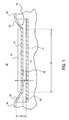
- Figure 1 is an elevational cross-section view of the inventive variable capacitor that is designated by the reference numeral 10.
- Figure 1 illustrates a substrate 12 in which a fixed charge plate 14 is disposed.
- a movable charge plate 16 is disposed above fixed charge plate 14.
- Movable charge plate 16 may be characterized by a planar portion 18, a suspension portion 20, and a terminal portion 40.
- Affixed to planar portion 18 of movable charge plate 16 is a stiffener 22. Stiffener 22 may occupy the same footprint as planar portion 18 of movable charge plate 16.
- a first separation distance 24 is observed as the original separation distance between fixed charge plate 14 and planar portion 18 before an actuation force is applied.
- a second separation distance 26 is observed between planar portion 18 of movable charge plate 16 and fixed charge plate 14 as the tunable capacitor separation distance at a given applied actuation force.
- Stiffener 22 may be made of any material that causes planar portion 18 of movable charge plate 16 to resist bending.
- stiffener 22 is made of silicon nitride, Si x N y , where x and y have values that make up both stoichiometric and solid solution combinations.
- Stiffener 22 may also be made of oxides such as silica, titania, alumina, ceria, thoria, and other oxides that make up both stoichiometric and solid solution combinations.
- stiffener 22 may be made of any material, preferably dielectric, that allows the inventive structure to achieve a tunable range greater than about 30%, preferably greater than about 50%, and more preferably greater than about 100%.
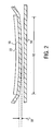
- Second separation distance 26 is observed to be substantially constant.
- substantially constant it is meant that warping of planar portion 18 of movable charge plate 16 is minimized.
- Relative warping is defined as a relative measure of deflection of any point along the charge surface 28 of planar portion 18 in vertical relation to any other point thereon, divided by the length 30 of planar portion.
- Figure 2 is an exaggerated detail illustration of relative warping wherein the deflection difference 32, can be relatively quantified by dividing by length 30.
- Relative warping in the present invention may be in a range from about 30% to about 0.1%, preferably from about 10% to about 0.5% and most preferably from about 2% to about 1%.
- first separation distance 24 is the measurement from terminal portion 40 of movable charge plate 16 to down to fixed charge plate 14.
- Suspension portion 20 of movable charge plate 16 is separated from fixed charge plate 14 over a variable distance that is at a maximum at first separation distance 24 and at a minimum at second separation distance. Consequently, removing material in this portion preferably reduces capacitance for suspension portion 20.
- FIG. 3 is a top view of variable capacitor 10 that further illustrates the present invention.
- Stiffener 22 has been removed to further illustrate movable charge plate 16.
- Movable charge plate 16 is seen as comprising planar portion 18 and suspension portion 20 that meet an angle at a bend depicted by the dashed line 36, and terminal portion 40. Terminal portion 40 and suspension portion 20 also meet at an angle at a bend depicted by the dashed line 58.
- FIG. 3 illustrates that suspension portion 20 may contain through holes 34 to form a broken surface suspension of planar portion 18.
- the broken surface of suspension portion 20 of movable charge plate 16 reduces capacitance surface area for that section of movable charge plate 16 by reducing the amount of charge surface area that is present at the variable first separation distance 24. Thereby the broken surface of suspension portion 20 allows for better control of the variable capacitor quality of the present invention. Additionally, because there is less material that must bend in suspension portion 20 when it has a broken surface suspension, movable charge plate 16 is more pliable and therefore more easily tunable. It is understood that suspension portion 20 may also be solid. Where suspension portion 20 has a broken surface, fixed charge plate 14 has a first surface area and movable charge plate 16 has a second surface area that is smaller than the first surface area.
- the capacitor according to the present invention has a movable charge plate that is divided into a solid surface charge plate portion and a broken surface suspension.
- Figure 4 is an elevational cross-section view of another variable capacitor 400 that illustrates another embodiment of the present invention.
- Figure 4 illustrates a flexible dielectric material 438 that has a movable charge plate 416 disposed thereon and that is suspended above a fixed charge plate 414. It is noted that movable charge plate 416 cannot make electrical contact with fixed charge plate 414 because flexible dielectric material 438 is interposed therebetween.
- flexible dielectric material 438 is divided into a planar subsection 418, a suspension subsection 420, and a terminal subsection 440.
- a stiffener 22 is disposed upon flexible dielectric material 438.
- Stiffener 22 has a footprint that may be substantially the same as movable charge plate 416 as well as planar subsection 418.
- Movable charge plate 416 is interposed between stiffener 22 and planar subsection 418.
- stiffener 22 is illustrated as entirely cloaking movable charge plate 416 from a top-down view in Figure 4 , it is understood that stiffener 22 may have a footprint that is larger, the same as, or smaller than movable charge plate 416. Where stiffener 22 is larger, it may be larger by a factor range from about 1.01 to about 2, preferably from about 1.1 to about 1.5.
- the at least one through hole 34 has an area, relative to the total area of flexible dielectric 438, in a range from about 1% to about 50%, preferably from about 10% to about 40%.
- Figure 5 is another embodiment of the present invention.
- a stiffener 22 is superimposed over a movable charge plate 516.
- stiffener 22 obscures the planar portion 518 of movable charge plate 516.
- the suspension portion 520 of movable charge plate 516 forms a spring in the shape of an undulating suspension between planar portion 518 and the terminal portion 540 of movable charge plate 516.
- greater flexibility may be achieved for the actuation of planar portion 518 of movable charge plate 516.
- Figure 5 illustrates suspension portion 520 with "W" and "M" shapes.
- suspension 620 has both "U” shaped and an inverted horseshoe shaped undulating connections between planar portion 618 and the terminal portion 640 of movable charge plate 616.
- suspension portion 720 has both "S" and backward “S” shapes that undulate between planar portion 718 and the terminal portion 740 of movable charge plate 716.
- the undulating suspensions 520, 620, and 720 depicted in Figures 5, 6 , and 7 are presented as portions of movable charge plates 516, 716, and 716, respectively, it is understood that the undulating suspensions 520, 620, and 720 may also be integral portions of flexible dielectric materials.
- the integral portions of flexible dielectric materials may be for structures depicted in Figure 4 .
- the undulating configuration that constitutes the suspension portion of the flexible dielectric may be a continuous undulating structure that extends across the planar portion of the movable charge plate to create a multiple channel open configuration. Accordingly, where Figure 4 may illustrate a continuous undulating structure, it may begin at one terminal portion 440, continue as one suspension portion 420, continue as planar portion 418, and finish as the other suspension portion 420 and terminal portion 440, respectively.
- suspension portion 520 of movable charge plate 516 has a thickness 542 and amplitude 544 that may be related to the length 530 and/or the width 546 of movable charge plate 516.
- suspension portion 620 of movable charge plate 616 has a thickness 642 and amplitude 644 that may be related to the length 630 and/or the width 646 of movable charge plate 616.
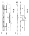
- Figure 8 illustrates another embodiment of the present invention in which the functions of capacitance and electrostatic actuation are separated.
- Fixed charge plates 814 may be elevated upon the substrate 812 above an actuator plate 848.
- Actuator plate 848 is disposed upon a lower substrate 850.
- the elevation of fixed charge plates 814 may be negligible or omitted to achieve a structure where fixed charge plates 814 and fixed actuator plate 848 are at substantially the same level.
- substrates 812 and 850 may be the same level and fashioned from the same material layer in a single process step.
- the movable charge plate 816 is affixed to a stiffener 822. Together, movable charge plate 816 and stiffener 822 are actuated by actuator plate 848 to establish a preferred separation distance 826 for a desired capacitance. Actuator plate 848 uses electromotive force to reposition movable charge plate 816 to a desired separation distance 826.
- Figure 9 illustrates another embodiment of the present invention similar to the embodiment depicted in Figure 8 , with the addition that there is a plurality of movable charge plates 916 that are isolated from a movable actuator plate 952.
- the establishment of a preferred capacitance may be carried out where the electromotive force applied between the fixed actuator plate 948 and the movable actuator plates 952.
- This actuation scheme has a diminished effect, if any, upon the capacitance that is established between the fixed charge plates 914 and movable charge plates 916. Accordingly, the desired capacitance established may be more directly related to the separation distance 926.
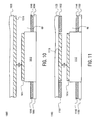
- Figure 10 illustrates yet another embodiment of the present invention in which the functions of capacitance and electrostatic actuation are separated.
- a fixed charge plate 1014 may be elevated upon the substrate 1012 above an actuator plate 1048.
- Actuator plate 1048 is disposed upon a lower substrate 1050.
- the elevation of fixed charge plate 1014 may be negligible or omitted to achieve a structure where fixed charge plate 1014 and fixed actuator plate 1048 are at substantially the same level.
- substrates 1012 and 1050 may be the same level and fashioned from the same material layer in a single process step.
- the movable charge plate 1016 is affixed to a stiffener 1022. Together, movable charge plate 1016 and stiffener 1022 are actuated by actuator plate 1048 to establish a preferred separation distance 1026 for a desired capacitance. Actuator plate 1048 uses electromotive force to reposition movable charge plate 1016 to a desired separation distance 1026.
- Figure 11 illustrates another embodiment of the present invention similar to the embodiment depicted in Figure 10 , with the addition that the movable charge plate 1116 is isolated from movable actuator plates 1152.
- the establishment of a preferred capacitance may be carried out where the electromotive force applied between the fixed actuator plate 1148 and the movable actuator plate 1152.
- This actuation scheme has a diminished effect, if any, upon the capacitance that is established between the fixed charge plate 1114 and movable charge plate 1116. Accordingly, the desired capacitance established may be more directly related to the separation distance 1126.
- suspension of the movable charge plate may be carried out by the suspension portion embodiments as set forth in this disclosure. Additionally, other suspension schemes may be used for this embodiment of the invention.
- the suspension sections 20, 420, 520, 620, and 720 are examples of a means for suspending the movable charge plate.
- the fixed charge plates 14, 414, 848, 948, 1048, and 1148 are examples of a means for moving the movable charge plate.
- variable capacitor is made according to an inventive method 1200 that is illustrated in Figure 12 .
- a recess 60 is formed in substrate 12 as depicted in Figure 1 .
- Recess 60 may be formed of a single etch, or it may be part of a damascene structure.
- Fixed charge plate 14 is formed in recess 60 by deposition such as chemical vapor deposition (CVD) or physical vapor deposition (PVD).
- CVD chemical vapor deposition
- PVD physical vapor deposition
- the method illustrated in Figure 12 demonstrates that formation of the recess and the fixed charge plate may be contemporaneous as depicted in flow block 1210.
- Movable charge plate 16 is formed above fixed charge plate 14 as depicted in process flow block 1230.
- Movable charge plate 16 is formed by a method such as filling recess 60 with a temporary material, depositing movable charge plate 16, and wet etching the temporary filler material that filled recess 60.
- Stiffener 22 is formed upon a portion of movable charge plate 16 as depicted in flow block 1240. Where patterning of at least a portion of movable charge plate 16 precedes removal of filler material in recess 60, patterning of multiple through-holes 34 or any one of the undulating suspension sections as disclosed herein, will facilitate removal of the filler material.
- variable capacitor 400 illustrated in Figure 4 is formed in a manner similar to variable capacitor 10.
- flexible dielectric layer 438 Prior to formation of movable charge plate 16, flexible dielectric layer 438 is formed upon a filler material that is to be removed to form recess 60 as depicted in process flow block 1220. After flexible dielectric layer 438 is formed, patterning may precede or follow removal of the filler material disposed in recess 60. Where patterning of flexible dielectric layer 438 precedes removal of the filler material in recess 60, patterning of any one of the undulating suspension sections as disclosed herein, will facilitate removal of the filler material.
- variable capacitor 800 depicted in Figure 8 is formed by forming lower substrate 850 in recess 60 and forming fixed actuator plate 848 upon lower substrate 850.
- Elevated substrate 812 is formed either by depositing or etching into a portion of recess 60.
- Fixed charge plate 814 is formed upon elevated substrate 812 and a filler material to be removed fills recess 60 during the formation of flexible dielectric layer (not pictured) according to embodiments set forth herein. Where fixed charge plate 814 and fixed actuator plate 848 are at the same height, they may be patterned from the same metal layer.
- Variable capacitor 900 is formed by a similar method with the added limitation that movable charge plates 916 are patterned to form movable actuator plate 952.
- variable capacitor 1000 depicted in Figure 10 is formed by forming lower substrate 1050 in recess 60 and forming fixed actuator plate 1048 upon lower substrate 1050. Elevated substrate 1012 is formed either by depositing or etching into a portion of recess 60. Fixed charge plate 1014 is formed upon elevated substrate 1012 and a filler material to be removed fills recess 60 during the formation of flexible dielectric layer (not pictured) according to embodiments set forth herein. Where fixed charge plate 1014 and fixed actuator plate 1048 are at the same height, they may be patterned from the same metal layer.
- Variable capacitor 1100 is formed by a similar method with the added limitation that movable charge plate 1116 is patterned to form movable actuator plate 1152.
- variable capacitor of the present invention may enable a wireless device to operate at multiple bands such as 900 MHz, 1.9 GHz, and 2.4 GHz.
- transceiver design may be changed to enable the same variable capacitor to be used for the various frequencies.
- Another advantage is that the establishment and control over a preferred capacitance is more predictable and therefore more reliable.
- the presence of the stiffener and the broken surface suspension significantly reduces the capacitance that does not change near the terminal ends of variable capacitors of the prior art. Further, the separation of actuation and capacitance as disclosed herein allows for greater control
Abstract
Description
- The present invention relates generally to microelectromechanical structure (MEMS) fabrication, and, more specifically, the present invention relates to the fabrication of a variable capacitor that is tunable over a wide range.
- As microelectronic technology continues to experience miniaturization and, greater device flexibility, the need has arisen for variable capacitors that can have greater capability and reliability. Prior art on-chip variable capacitors are based on varactor diode technology that have a tuning range of less than about 25%. The varactor diode technology also has a low pull-in effect.
- Additionally, prior art membrane capacitors have a capacitance tunable range that is limited due to the voltage exceeding the critical voltage (Vc) thereof. At Vc, the membrane collapses and the capacitor shorts out. Additionally, due to the suspension nature of the prior art capacitors, the center portion of the flexible membrane draws closer to the fixed electrode than the edge portions. This phenomenon creates a greater local capacitance at the center of the flexible membrane than at the edge portions of the flexible membrane where it is anchored.
- Between capacitors, it is difficult to control capacitance change in any predictable way such as a linear or even a nonlinear functional correlation between the amount of applied direct current (DC) voltage and the resulting capacitance. Where the edge portions of the flexible membrane occupies a substantial capacitance surface area in relation to the center portion, it becomes difficult to achieve an appreciable range of tunable capacitance.
What is needed is a variable capacitor that overcomes the problems in the prior art. - In order that the manner in which the above-recited and other advantages of the invention are obtained, a more particular description of the invention briefly described above will be rendered by reference to specific embodiments thereof which are illustrated in the appended drawings. In the drawings, like structures will be provided with like reference designations. In order to show the structures of the present invention most clearly, the drawings included herein are diagrammatic representations of integrated circuit structures. Thus, the actual appearance of the fabricated structures, for example in a photomicrograph, may appear different while still incorporating the essential structures of the present invention. Moreover, the drawings show only the structures necessary to understand the present invention. Additional structures known in the art have not been included to maintain the clarity of the drawings. Understanding that these drawings depict only typical embodiments of the invention that are not necessarily drawn to scale and are not therefore to be considered to be limiting of its scope, the invention will be described and explained with additional specificity and detail through the use of the accompanying drawings in which:
-
Figure 1 is an elevational cross-section view of a variable capacitor according to the present invention; -
Figure 2 is an exaggerated elevational cross-section view the variable capacitor to illustrate relative warping of a MEMS device; -
Figure 3 is a top cut-away view of the variable capacitor depicted inFigure 1 ; -
Figure 4 is an elevational cross-section view of another embodiment of the variable capacitor; -
Figure 5 is a top view of an alternative embodiment of the variable capacitor depicted inFigure 1 ; -
Figure 6 is a top view of an alternative embodiment of the variable capacitor depicted inFigure 1 ; -
Figure 7 is a top view of an alternative embodiment of the variable capacitor depicted inFigure 1 ; -
Figure 8 is an elevational cross-section view of another embodiment of the variable capacitor; -
Figure 9 is an elevational cross-section view of an alternative embodiment of the variable capacitor depicted inFigure 8 ; -
Figure 10 is an elevational cross-section view of another embodiment of the variable capacitor; -
Figure 11 is an elevational cross-section view of an alternative embodiment of the variable capacitor depicted inFigure 10 ; and
Figure 12 is a process flow diagram that illustrates the inventive method. - The present invention relates to a variable capacitor that is a micro-electromechanical system (MEMS). The variable capacitor overcomes problems inherent in the prior art by stiffening a movable charge plate and by making variable capacitance a more linear function of the actuation force applied, and by accomplishing a much larger tuning range.
- A first aspect of the present invention relates to the prevention of collapse of the capacitor. Thereby, the tunable range is increased over the prior art by a factor of at least two, and preferably by a factor of at least four and higher.
-
Figure 1 is an elevational cross-section view of the inventive variable capacitor that is designated by thereference numeral 10.Figure 1 illustrates asubstrate 12 in which afixed charge plate 14 is disposed. Amovable charge plate 16 is disposed above fixedcharge plate 14.Movable charge plate 16 may be characterized by aplanar portion 18, asuspension portion 20, and aterminal portion 40. Affixed toplanar portion 18 ofmovable charge plate 16 is astiffener 22. Stiffener 22 may occupy the same footprint asplanar portion 18 ofmovable charge plate 16. - A
first separation distance 24 is observed as the original separation distance betweenfixed charge plate 14 andplanar portion 18 before an actuation force is applied. Similarly, asecond separation distance 26 is observed betweenplanar portion 18 ofmovable charge plate 16 andfixed charge plate 14 as the tunable capacitor separation distance at a given applied actuation force. -
Stiffener 22 may be made of any material that causesplanar portion 18 ofmovable charge plate 16 to resist bending. Preferably,stiffener 22 is made of silicon nitride, SixNy, where x and y have values that make up both stoichiometric and solid solution combinations. Stiffener 22 may also be made of oxides such as silica, titania, alumina, ceria, thoria, and other oxides that make up both stoichiometric and solid solution combinations. Additionally,stiffener 22 may be made of any material, preferably dielectric, that allows the inventive structure to achieve a tunable range greater than about 30%, preferably greater than about 50%, and more preferably greater than about 100%. -
Second separation distance 26 is observed to be substantially constant. By "substantially constant," it is meant that warping ofplanar portion 18 ofmovable charge plate 16 is minimized. Relative warping is defined as a relative measure of deflection of any point along thecharge surface 28 ofplanar portion 18 in vertical relation to any other point thereon, divided by thelength 30 of planar portion.Figure 2 is an exaggerated detail illustration of relative warping wherein thedeflection difference 32, can be relatively quantified by dividing bylength 30. Relative warping in the present invention may be in a range from about 30% to about 0.1%, preferably from about 10% to about 0.5% and most preferably from about 2% to about 1%. - Referring again to
Figure 1 ,first separation distance 24 is the measurement fromterminal portion 40 ofmovable charge plate 16 to down tofixed charge plate 14.Suspension portion 20 ofmovable charge plate 16 is separated fromfixed charge plate 14 over a variable distance that is at a maximum atfirst separation distance 24 and at a minimum at second separation distance. Consequently, removing material in this portion preferably reduces capacitance forsuspension portion 20. -
Figure 3 is a top view ofvariable capacitor 10 that further illustrates the present invention.Stiffener 22 has been removed to further illustratemovable charge plate 16.Movable charge plate 16 is seen as comprisingplanar portion 18 andsuspension portion 20 that meet an angle at a bend depicted by thedashed line 36, andterminal portion 40.Terminal portion 40 andsuspension portion 20 also meet at an angle at a bend depicted by thedashed line 58. -
Figure 3 illustrates thatsuspension portion 20 may contain throughholes 34 to form a broken surface suspension ofplanar portion 18. The broken surface ofsuspension portion 20 ofmovable charge plate 16 reduces capacitance surface area for that section ofmovable charge plate 16 by reducing the amount of charge surface area that is present at the variablefirst separation distance 24. Thereby the broken surface ofsuspension portion 20 allows for better control of the variable capacitor quality of the present invention. Additionally, because there is less material that must bend insuspension portion 20 when it has a broken surface suspension,movable charge plate 16 is more pliable and therefore more easily tunable. It is understood thatsuspension portion 20 may also be solid. Wheresuspension portion 20 has a broken surface, fixedcharge plate 14 has a first surface area andmovable charge plate 16 has a second surface area that is smaller than the first surface area. - In a preferred embodiment, the capacitor according to the present invention has a movable charge plate that is divided into a solid surface charge plate portion and a broken surface suspension.
-
Figure 4 is an elevational cross-section view of anothervariable capacitor 400 that illustrates another embodiment of the present invention.Figure 4 illustrates a flexibledielectric material 438 that has amovable charge plate 416 disposed thereon and that is suspended above a fixedcharge plate 414. It is noted thatmovable charge plate 416 cannot make electrical contact with fixedcharge plate 414 because flexibledielectric material 438 is interposed therebetween. - In this embodiment, flexible
dielectric material 438 is divided into aplanar subsection 418, asuspension subsection 420, and aterminal subsection 440. Astiffener 22 is disposed upon flexibledielectric material 438.Stiffener 22 has a footprint that may be substantially the same asmovable charge plate 416 as well asplanar subsection 418.Movable charge plate 416 is interposed betweenstiffener 22 andplanar subsection 418. Althoughstiffener 22 is illustrated as entirely cloakingmovable charge plate 416 from a top-down view inFigure 4 , it is understood thatstiffener 22 may have a footprint that is larger, the same as, or smaller thanmovable charge plate 416. Wherestiffener 22 is larger, it may be larger by a factor range from about 1.01 to about 2, preferably from about 1.1 to about 1.5. - In the process of forming at least one through hole 34 (not pictured in
Figure 4 ) in the flexible dielectric below the movable charge plate, the at least one throughhole 34 has an area, relative to the total area offlexible dielectric 438, in a range from about 1% to about 50%, preferably from about 10% to about 40%. -
Figure 5 is another embodiment of the present invention. In this embodiment, astiffener 22 is superimposed over amovable charge plate 516. In this embodiment,stiffener 22 obscures theplanar portion 518 ofmovable charge plate 516. In this embodiment, thesuspension portion 520 ofmovable charge plate 516 forms a spring in the shape of an undulating suspension betweenplanar portion 518 and theterminal portion 540 ofmovable charge plate 516. By this embodiment, greater flexibility may be achieved for the actuation ofplanar portion 518 ofmovable charge plate 516.Figure 5 illustratessuspension portion 520 with "W" and "M" shapes. - Although these shapes are one preferred embodiment, simpler or more complex shapes may be achieved. One example of a simpler shape is illustrated in
Figure 6 . InFigure 6 ,suspension 620 has both "U" shaped and an inverted horseshoe shaped undulating connections betweenplanar portion 618 and theterminal portion 640 ofmovable charge plate 616. Another example of a simpler shape is illustrated inFigure 7 . InFigure 7 ,suspension portion 720 has both "S" and backward "S" shapes that undulate betweenplanar portion 718 and theterminal portion 740 ofmovable charge plate 716. - Although the undulating
suspensions Figures 5, 6 , and7 are presented as portions ofmovable charge plates suspensions Figure 4 . - In an alternative embodiment, the undulating configuration that constitutes the suspension portion of the flexible dielectric, may be a continuous undulating structure that extends across the planar portion of the movable charge plate to create a multiple channel open configuration. Accordingly, where
Figure 4 may illustrate a continuous undulating structure, it may begin at oneterminal portion 440, continue as onesuspension portion 420, continue asplanar portion 418, and finish as theother suspension portion 420 andterminal portion 440, respectively. - Different degrees of flexibility are achieved by the particular material used, whether charge plate material or flexible dielectric material, and by the dimensions of the undulating structures. For example,
suspension portion 520 ofmovable charge plate 516 has athickness 542 andamplitude 544 that may be related to thelength 530 and/or thewidth 546 ofmovable charge plate 516. Similarly, thesuspension portion 620 ofmovable charge plate 616 has a thickness 642 andamplitude 644 that may be related to thelength 630 and/or thewidth 646 ofmovable charge plate 616. -
Figure 8 illustrates another embodiment of the present invention in which the functions of capacitance and electrostatic actuation are separated. Fixedcharge plates 814 may be elevated upon thesubstrate 812 above anactuator plate 848.Actuator plate 848 is disposed upon alower substrate 850. The elevation of fixedcharge plates 814 may be negligible or omitted to achieve a structure where fixedcharge plates 814 and fixedactuator plate 848 are at substantially the same level. For this alternative embodiment,substrates - The movable charge plate 816 is affixed to a
stiffener 822. Together, movable charge plate 816 andstiffener 822 are actuated byactuator plate 848 to establish apreferred separation distance 826 for a desired capacitance.Actuator plate 848 uses electromotive force to reposition movable charge plate 816 to a desiredseparation distance 826. -
Figure 9 illustrates another embodiment of the present invention similar to the embodiment depicted inFigure 8 , with the addition that there is a plurality ofmovable charge plates 916 that are isolated from amovable actuator plate 952. According to this embodiment, the establishment of a preferred capacitance may be carried out where the electromotive force applied between the fixedactuator plate 948 and themovable actuator plates 952. This actuation scheme has a diminished effect, if any, upon the capacitance that is established between the fixedcharge plates 914 andmovable charge plates 916. Accordingly, the desired capacitance established may be more directly related to the separation distance 926. -
Figure 10 illustrates yet another embodiment of the present invention in which the functions of capacitance and electrostatic actuation are separated. A fixedcharge plate 1014 may be elevated upon thesubstrate 1012 above anactuator plate 1048.Actuator plate 1048 is disposed upon alower substrate 1050. The elevation of fixedcharge plate 1014 may be negligible or omitted to achieve a structure where fixedcharge plate 1014 and fixedactuator plate 1048 are at substantially the same level. For this alternative embodiment,substrates - The
movable charge plate 1016 is affixed to astiffener 1022. Together,movable charge plate 1016 andstiffener 1022 are actuated byactuator plate 1048 to establish apreferred separation distance 1026 for a desired capacitance.Actuator plate 1048 uses electromotive force to repositionmovable charge plate 1016 to a desiredseparation distance 1026. -
Figure 11 illustrates another embodiment of the present invention similar to the embodiment depicted inFigure 10 , with the addition that themovable charge plate 1116 is isolated frommovable actuator plates 1152. According to this embodiment, the establishment of a preferred capacitance may be carried out where the electromotive force applied between the fixedactuator plate 1148 and themovable actuator plate 1152. This actuation scheme has a diminished effect, if any, upon the capacitance that is established between the fixedcharge plate 1114 andmovable charge plate 1116. Accordingly, the desired capacitance established may be more directly related to theseparation distance 1126. - In the embodiments set forth in
Figures 8, 9 ,10 and 11 , it is understood that suspension of the movable charge plate may be carried out by the suspension portion embodiments as set forth in this disclosure. Additionally, other suspension schemes may be used for this embodiment of the invention. - In the forgoing embodiments, the
suspension sections charge plates - The variable capacitor is made according to an
inventive method 1200 that is illustrated inFigure 12 . Arecess 60 is formed insubstrate 12 as depicted inFigure 1 .Recess 60 may be formed of a single etch, or it may be part of a damascene structure. Fixedcharge plate 14 is formed inrecess 60 by deposition such as chemical vapor deposition (CVD) or physical vapor deposition (PVD). The method illustrated inFigure 12 demonstrates that formation of the recess and the fixed charge plate may be contemporaneous as depicted inflow block 1210.Movable charge plate 16 is formed above fixedcharge plate 14 as depicted inprocess flow block 1230.Movable charge plate 16 is formed by a method such as fillingrecess 60 with a temporary material, depositingmovable charge plate 16, and wet etching the temporary filler material that filledrecess 60.Stiffener 22 is formed upon a portion ofmovable charge plate 16 as depicted inflow block 1240. Where patterning of at least a portion ofmovable charge plate 16 precedes removal of filler material inrecess 60, patterning of multiple through-holes 34 or any one of the undulating suspension sections as disclosed herein, will facilitate removal of the filler material. - The
variable capacitor 400 illustrated inFigure 4 is formed in a manner similar tovariable capacitor 10. Prior to formation ofmovable charge plate 16,flexible dielectric layer 438 is formed upon a filler material that is to be removed to formrecess 60 as depicted inprocess flow block 1220. Afterflexible dielectric layer 438 is formed, patterning may precede or follow removal of the filler material disposed inrecess 60. Where patterning of flexibledielectric layer 438 precedes removal of the filler material inrecess 60, patterning of any one of the undulating suspension sections as disclosed herein, will facilitate removal of the filler material. - The
variable capacitor 800 depicted inFigure 8 is formed by forminglower substrate 850 inrecess 60 and forming fixedactuator plate 848 uponlower substrate 850.Elevated substrate 812 is formed either by depositing or etching into a portion ofrecess 60. Fixedcharge plate 814 is formed uponelevated substrate 812 and a filler material to be removed fillsrecess 60 during the formation of flexible dielectric layer (not pictured) according to embodiments set forth herein. Where fixedcharge plate 814 and fixedactuator plate 848 are at the same height, they may be patterned from the same metal layer.Variable capacitor 900 is formed by a similar method with the added limitation thatmovable charge plates 916 are patterned to formmovable actuator plate 952. - The
variable capacitor 1000 depicted inFigure 10 is formed by forminglower substrate 1050 inrecess 60 and forming fixedactuator plate 1048 uponlower substrate 1050.Elevated substrate 1012 is formed either by depositing or etching into a portion ofrecess 60. Fixedcharge plate 1014 is formed uponelevated substrate 1012 and a filler material to be removed fillsrecess 60 during the formation of flexible dielectric layer (not pictured) according to embodiments set forth herein. Where fixedcharge plate 1014 and fixedactuator plate 1048 are at the same height, they may be patterned from the same metal layer.Variable capacitor 1100 is formed by a similar method with the added limitation thatmovable charge plate 1116 is patterned to formmovable actuator plate 1152. - Distinct advantages exist for the present invention. One advantage is that a tunable range is achieved that was not achievable in the prior art. Because of the presence of a stiffener as disclosed herein, the critical gap between the movable charge plate and the fixed charge plate can be smaller than what was allowable in the prior art. Consequently, the tunable range of the variable capacitor may be more than 100%. As applied to wireless technology, by way of non-limiting example, the variable capacitor of the present invention may enable a wireless device to operate at multiple bands such as 900 MHz, 1.9 GHz, and 2.4 GHz. Thus, transceiver design may be changed to enable the same variable capacitor to be used for the various frequencies.
- Another advantage is that the establishment and control over a preferred capacitance is more predictable and therefore more reliable. The presence of the stiffener and the broken surface suspension significantly reduces the capacitance that does not change near the terminal ends of variable capacitors of the prior art. Further, the separation of actuation and capacitance as disclosed herein allows for greater control
- It will be readily understood to those skilled in the art that various other changes in the details, material, and arrangements of the parts and method stages which have been described and illustrated in order to explain the nature of this invention may be made without departing from the principles and scope of the invention as expressed in the subjoined claims.
Claims (21)
- A variable capacitor comprising:a fixed charge plate (14) disposed in a substrate;a movable charge plate (16) disposed above the fixed charge plate (14) wherein the movable charge plate (16) comprises a solid surface plate (18) and a broken surface suspension (20); anda stiffener (22) affixed to the movable charge plate (16).
- The capacitor according to claim 1, the movable charge plate (16) further comprising:a first separation distance between the fixed charge plate (14) and the stiffener (22), wherein the first separation distance is constant.
- The capacitor according to claim 1, further comprising:a first separation distance between the fixed charge plate (14) and the stiffener (22), wherein the first separation distance is constant; anda second separation distance between the fixed charge plate (14) and portions of the movable charge plate (16),wherein the second separation distance is tunable.
- The capacitor according to claim 1, wherein the fixed charge plate (14) has a first surface area and the movable charge plate (16) has a second surface area that is smaller than the first surface area.
- The capacitor according to claim 1, wherein the broken surface suspension has an undulating configuration.
- The capacitor according to claim 1, wherein the fixed charge plate (14) has a first surface area and the movable charge plate (16) has a second surface area that is smaller than the first surface area, wherein the movable charge plate (16) comprises a solid surface plate and a broken surface suspension, and wherein the broken surface suspension has an undulating configuration.
- The capacitor according to claim 1, implemented in a semiconductor device.
- The capacitor according to claim 1, wherein the broken surface suspension (20) comprises a flexible dielectric layer.
- The capacitor according to claim 1, wherein the broken surface suspension (20) comprises a flexible section of the movable charge plate (16).
- A microelectromechanical structure comprising a capacitor according to one of the preceding claims.
- A method of forming a variable capacitor comprising:forming a recess in a substrate;forming a fixed charge plate (14) in the recess;forming a movable charge plate (16) above the fixed charge plate (14), wherein the movable charge plate (16) comprises a solid surface plate (18) and a broken surface suspension (20); andforming a stiffener (22) upon a portion of the movable charge plate (16).
- The method according to claim 11, further comprising:forming a dielectric layer upon the fixed charge plate (14);forming the movable charge plate (16) upon the dielectric layer; andremoving the dielectric layer between the fixed charge plate (14) and the movable charge plate (16).
- The method according to claim 11, further comprising, prior to forming a movable charge plate (16):forming a flexible dielectric above the fixed charge plate (14).
- The method according to claim 11, further comprising, prior to forming a movable charge plate (16):forming a flexible dielectric above the fixed charge plate (14); andforming multiple through holes in the flexible dielectric.
- The method according to claim 11, further comprising, prior to forming a movable charge plate (16):forming a flexible dielectric above the fixed charge plate (14); andforming multiple through holes in the flexible dielectric, wherein the multiple through holes have a relative area in a range from about 1% to about 50%.
- The method according to claim 11, further comprising, prior to forming a movable charge plate (16):forming a flexible dielectric above the fixed charge plate (14); andforming at least one through hole in the flexible dielectric.
- The method according to claim 11, further comprising, prior to forming a movable charge plate (16):forming a flexible dielectric above the fixed charge plate (14); andforming at least one through hole in the flexible dielectric below the movable charge plate (16),wherein the at least one through hole has a relative area in a range from about 10% to about 40%.
- The method according to claim 11, further comprising, prior to forming a movable charge plate (16):forming a flexible dielectric above the fixed charge plate (14); andpatterning an undulating suspension section in at least a portion of the flexible dielectric.
- The method according to claim 11, wherein prior to forming a stiffener (22), forming a movable charge plate (16) further comprises: patterning an undulating suspension section in at least a portion of the movable charge plate (16).
- The method according to claim 11, wherein forming a recess in the substrate further comprises:forming a lower substrate portion in the recess;forming a fixed actuator plate upon the lower substrate portion;forming an elevated substrate portion in the recess; andforming the fixed charge plate (14) upon the elevated substrate.
- The method according to claim 11, wherein forming a movable charge plate (16) further comprises:patterning the movable charge plate (16) to form movable actuator plate.
Applications Claiming Priority (2)
| Application Number | Priority Date | Filing Date | Title |
|---|---|---|---|
| US09/491,560 US6355534B1 (en) | 2000-01-26 | 2000-01-26 | Variable tunable range MEMS capacitor |
| EP01908665A EP1250707B1 (en) | 2000-01-26 | 2001-01-22 | Variable capacitor and method of forming it |
Related Parent Applications (2)
| Application Number | Title | Priority Date | Filing Date |
|---|---|---|---|
| EP01908665A Division EP1250707B1 (en) | 2000-01-26 | 2001-01-22 | Variable capacitor and method of forming it |
| EP01908665.1 Division | 2001-01-22 |
Publications (2)
| Publication Number | Publication Date |
|---|---|
| EP1942509A1 true EP1942509A1 (en) | 2008-07-09 |
| EP1942509B1 EP1942509B1 (en) | 2013-06-19 |
Family
ID=23952734
Family Applications (2)
| Application Number | Title | Priority Date | Filing Date |
|---|---|---|---|
| EP01908665A Expired - Lifetime EP1250707B1 (en) | 2000-01-26 | 2001-01-22 | Variable capacitor and method of forming it |
| EP08004942.2A Expired - Lifetime EP1942509B1 (en) | 2000-01-26 | 2001-01-22 | Variable tunable range mems capacitor |
Family Applications Before (1)
| Application Number | Title | Priority Date | Filing Date |
|---|---|---|---|
| EP01908665A Expired - Lifetime EP1250707B1 (en) | 2000-01-26 | 2001-01-22 | Variable capacitor and method of forming it |
Country Status (7)
| Country | Link |
|---|---|
| US (2) | US6355534B1 (en) |
| EP (2) | EP1250707B1 (en) |
| AT (1) | ATE467221T1 (en) |
| AU (1) | AU2001236510A1 (en) |
| DE (1) | DE60142024D1 (en) |
| TW (1) | TW477991B (en) |
| WO (1) | WO2001056046A2 (en) |
Families Citing this family (52)
| Publication number | Priority date | Publication date | Assignee | Title |
|---|---|---|---|---|
| US6559024B1 (en) * | 2000-03-29 | 2003-05-06 | Tyco Electronics Corporation | Method of fabricating a variable capacity diode having a hyperabrupt junction profile |
| FR2808919B1 (en) * | 2000-05-15 | 2002-07-19 | Memscap | ELECTRONIC MICROCOMPONENT OF THE VARIABLE CAPACITY OR MICROSWITCH TYPE, OR METHOD FOR MANUFACTURING SUCH A COMPONENT |
| US6635919B1 (en) * | 2000-08-17 | 2003-10-21 | Texas Instruments Incorporated | High Q-large tuning range micro-electro mechanical system (MEMS) varactor for broadband applications |
| FR2818795B1 (en) * | 2000-12-27 | 2003-12-05 | Commissariat Energie Atomique | MICRO-DEVICE WITH THERMAL ACTUATOR |
| US6541892B2 (en) * | 2001-01-16 | 2003-04-01 | Agilent Technologies, Inc. | Actuator with a flexure arrangement to accommodate a long range of motion |
| EP1251577B1 (en) * | 2001-04-19 | 2007-04-25 | Interuniversitair Microelektronica Centrum Vzw | Fabrication of integrated tunable/switchable passive microwave and millimeter wave modules |
| EP1407464B1 (en) * | 2001-07-17 | 2011-03-09 | SMC Kabushiki Kaisha | Micro-electromechanical sensor |
| CN100470697C (en) * | 2001-08-20 | 2009-03-18 | 霍尼韦尔国际公司 | Snap action thermal switch |
| JP2003062798A (en) * | 2001-08-21 | 2003-03-05 | Advantest Corp | Actuator and switch |
| US20040212026A1 (en) * | 2002-05-07 | 2004-10-28 | Hewlett-Packard Company | MEMS device having time-varying control |
| US6657525B1 (en) * | 2002-05-31 | 2003-12-02 | Northrop Grumman Corporation | Microelectromechanical RF switch |
| US6661069B1 (en) * | 2002-10-22 | 2003-12-09 | International Business Machines Corporation | Micro-electromechanical varactor with enhanced tuning range |
| KR100450824B1 (en) * | 2002-11-06 | 2004-10-01 | 삼성전자주식회사 | Structure of radio frequency variable capacitor and method of manufacturing the same |
| FR2851368B1 (en) * | 2003-02-18 | 2008-03-07 | Agence Spatiale Europeenne | ELECTRONIC COMPONENTS COMPRISING MICRO ELECTROMECHANICAL CAPACITORS WITH ADJUSTABLE CAPABILITY |
| US6806563B2 (en) * | 2003-03-20 | 2004-10-19 | International Business Machines Corporation | Composite capacitor and stiffener for chip carrier |
| US6987432B2 (en) * | 2003-04-16 | 2006-01-17 | Robert Bosch Gmbh | Temperature compensation for silicon MEMS resonator |
| US6853476B2 (en) * | 2003-04-30 | 2005-02-08 | Hewlett-Packard Development Company, L.P. | Charge control circuit for a micro-electromechanical device |
| US6829132B2 (en) * | 2003-04-30 | 2004-12-07 | Hewlett-Packard Development Company, L.P. | Charge control of micro-electromechanical device |
| US7167135B2 (en) * | 2003-09-11 | 2007-01-23 | Intel Corporation | MEMS based tunable antenna for wireless reception and transmission |
| US6954348B1 (en) | 2003-11-21 | 2005-10-11 | Memx, Inc. | Tunable MEMS capacitor |
| KR100549003B1 (en) * | 2004-02-04 | 2006-02-02 | 삼성전자주식회사 | MEMS tunable capacitor having wide tuning range and method of fabricating the same |
| EP1761998A4 (en) | 2004-02-27 | 2011-05-11 | Georgia Tech Res Inst | Harmonic cmut devices and fabrication methods |
| US7646133B2 (en) * | 2004-02-27 | 2010-01-12 | Georgia Tech Research Corporation | Asymmetric membrane cMUT devices and fabrication methods |
| EP1769573A4 (en) * | 2004-02-27 | 2010-08-18 | Georgia Tech Res Inst | Multiple element electrode cmut devices and fabrication methods |
| US7068125B2 (en) * | 2004-03-04 | 2006-06-27 | Robert Bosch Gmbh | Temperature controlled MEMS resonator and method for controlling resonator frequency |
| US7112951B2 (en) * | 2004-06-07 | 2006-09-26 | General Electric Company | MEMS based current sensor using magnetic-to-mechanical conversion and reference components |
| US7265019B2 (en) * | 2004-06-30 | 2007-09-04 | International Business Machines Corporation | Elastomeric CMOS based micro electromechanical varactor |
| US7623142B2 (en) | 2004-09-14 | 2009-11-24 | Hewlett-Packard Development Company, L.P. | Flexure |
| EP1645847B1 (en) * | 2004-10-08 | 2014-07-02 | STMicroelectronics Srl | Temperature compensated micro-electromechanical device and method of temperature compensation in a micro-electromechanical device |
| US7348928B2 (en) | 2004-12-14 | 2008-03-25 | Intel Corporation | Slot antenna having a MEMS varactor for resonance frequency tuning |
| US7957277B2 (en) * | 2005-02-25 | 2011-06-07 | Interdigital Technology Corporation | Wireless communication method and system for routing packets via intra-mesh and extra-mesh routes |
| US7786820B2 (en) * | 2005-03-21 | 2010-08-31 | Ngimat Co. | Tunable dielectric radio frequency microelectromechanical system capacitive switch |
| JP2006294866A (en) * | 2005-04-11 | 2006-10-26 | Toshiba Corp | Semiconductor device |
| US7345866B1 (en) * | 2005-05-13 | 2008-03-18 | Hrl Laboratories, Llc | Continuously tunable RF MEMS capacitor with ultra-wide tuning range |
| US7457033B2 (en) * | 2005-05-27 | 2008-11-25 | The Regents Of The University Of California | MEMS tunable vertical-cavity semiconductor optical amplifier |
| US7141989B1 (en) | 2006-04-10 | 2006-11-28 | Freescale Semiconductor, Inc. | Methods and apparatus for a MEMS varactor |
| DE102006040345B4 (en) * | 2006-08-29 | 2016-08-11 | Robert Bosch Gmbh | Micromechanical component and method for its production |
| JP4594340B2 (en) * | 2007-02-26 | 2010-12-08 | 富士通株式会社 | Micro movable device |
| JP2008211420A (en) * | 2007-02-26 | 2008-09-11 | Seiko Instruments Inc | Oscillator |
| WO2008152559A2 (en) | 2007-06-13 | 2008-12-18 | Nxp B.V. | Controller for tunable mems capacitor |
| US9099248B2 (en) | 2007-06-29 | 2015-08-04 | Corporation for National Research Iniatives | Variable capacitor tuned using laser micromachining |
| US8363380B2 (en) | 2009-05-28 | 2013-01-29 | Qualcomm Incorporated | MEMS varactors |
| US8218228B2 (en) * | 2009-12-18 | 2012-07-10 | Qualcomm Mems Technologies, Inc. | Two-terminal variable capacitance MEMS device |
| US20110148837A1 (en) * | 2009-12-18 | 2011-06-23 | Qualcomm Mems Technologies, Inc. | Charge control techniques for selectively activating an array of devices |
| JP5252016B2 (en) * | 2011-03-18 | 2013-07-31 | 横河電機株式会社 | Vibrating transducer |
| US9349786B2 (en) * | 2011-08-25 | 2016-05-24 | King Abdullah University Of Science And Technology | Fractal structures for fixed MEMS capacitors |
| CN104798154B (en) * | 2012-09-20 | 2018-04-03 | 维斯普瑞公司 | MEMS (MEMS) variable capacitor device and correlation technique |
| TWI571427B (en) * | 2013-03-08 | 2017-02-21 | 先技股份有限公司 | Boosted signal apparatus and method of boosted signal |
| US9506777B2 (en) | 2013-03-08 | 2016-11-29 | Sagatek Co., Ltd. | Micro-electromechanical apparatus having signal attenuation-proof function, and manufacturing method and signal attenuation-proof method thereof |
| US9443657B1 (en) | 2013-12-10 | 2016-09-13 | Tdk Corporation | Piezo controlled variable capacitor |
| US9474150B2 (en) | 2013-12-10 | 2016-10-18 | Tdk Corporation | Transmission line filter with tunable capacitor |
| US9424994B2 (en) | 2013-12-10 | 2016-08-23 | Tdk Corporation | Tunable interdigitated capacitor |
Citations (3)
| Publication number | Priority date | Publication date | Assignee | Title |
|---|---|---|---|---|
| US3341794A (en) * | 1965-07-26 | 1967-09-12 | Statham Instrument Inc | Transducers with substantially linear response characteristics |
| US5644349A (en) * | 1994-09-07 | 1997-07-01 | Xerox Corporation | Mechanical capacitor |
| EP1024508A2 (en) * | 1999-01-29 | 2000-08-02 | Fraunhofer-Gesellschaft Zur Förderung Der Angewandten Forschung E.V. | Electrostatically controllable capacity |
Family Cites Families (17)
| Publication number | Priority date | Publication date | Assignee | Title |
|---|---|---|---|---|
| NL301882A (en) * | 1962-12-17 | |||
| US3648340A (en) * | 1969-08-11 | 1972-03-14 | Gen Motors Corp | Hybrid solid-state voltage-variable tuning capacitor |
| US3993939A (en) * | 1975-01-07 | 1976-11-23 | The Bendix Corporation | Pressure variable capacitor |
| US4095263A (en) * | 1976-08-31 | 1978-06-13 | Johanson Manufacturing Corporation | Adjustable capacitors |
| US4198670A (en) * | 1978-11-20 | 1980-04-15 | General Motors Corporation | Capacitive pressure transducer |
| US4236137A (en) | 1979-03-19 | 1980-11-25 | Kulite Semiconductor Products, Inc. | Semiconductor transducers employing flexure frames |
| US4697159A (en) * | 1984-10-31 | 1987-09-29 | Rca Corporation | Tuning capacitors with selectable capacitance configurations for coupling between microwave circuits |
| US4674319A (en) * | 1985-03-20 | 1987-06-23 | The Regents Of The University Of California | Integrated circuit sensor |
| JPH0383314A (en) * | 1989-08-28 | 1991-04-09 | Murata Mfg Co Ltd | Variable capacitor |
| US5185690A (en) * | 1991-10-16 | 1993-02-09 | Miller Mark L | High dielectric constant sheet material |
| US5619061A (en) | 1993-07-27 | 1997-04-08 | Texas Instruments Incorporated | Micromechanical microwave switching |
| US5526172A (en) * | 1993-07-27 | 1996-06-11 | Texas Instruments Incorporated | Microminiature, monolithic, variable electrical signal processor and apparatus including same |
| JP2976842B2 (en) * | 1995-04-20 | 1999-11-10 | 日本電気株式会社 | Method for manufacturing semiconductor memory device |
| US5963788A (en) * | 1995-09-06 | 1999-10-05 | Sandia Corporation | Method for integrating microelectromechanical devices with electronic circuitry |
| US5766022A (en) * | 1996-05-21 | 1998-06-16 | International Business Machines Corporation | Electrical assembly |
| US5982608A (en) * | 1998-01-13 | 1999-11-09 | Stmicroelectronics, Inc. | Semiconductor variable capacitor |
| US6215644B1 (en) * | 1999-09-09 | 2001-04-10 | Jds Uniphase Inc. | High frequency tunable capacitors |
-
2000
- 2000-01-26 US US09/491,560 patent/US6355534B1/en not_active Expired - Lifetime
-
2001
- 2001-01-22 EP EP01908665A patent/EP1250707B1/en not_active Expired - Lifetime
- 2001-01-22 WO PCT/US2001/002202 patent/WO2001056046A2/en active Application Filing
- 2001-01-22 DE DE60142024T patent/DE60142024D1/en not_active Expired - Lifetime
- 2001-01-22 EP EP08004942.2A patent/EP1942509B1/en not_active Expired - Lifetime
- 2001-01-22 AU AU2001236510A patent/AU2001236510A1/en not_active Abandoned
- 2001-01-22 AT AT01908665T patent/ATE467221T1/en not_active IP Right Cessation
- 2001-02-16 TW TW090101646A patent/TW477991B/en not_active IP Right Cessation
- 2001-11-05 US US09/992,796 patent/US6980412B2/en not_active Expired - Fee Related
Patent Citations (3)
| Publication number | Priority date | Publication date | Assignee | Title |
|---|---|---|---|---|
| US3341794A (en) * | 1965-07-26 | 1967-09-12 | Statham Instrument Inc | Transducers with substantially linear response characteristics |
| US5644349A (en) * | 1994-09-07 | 1997-07-01 | Xerox Corporation | Mechanical capacitor |
| EP1024508A2 (en) * | 1999-01-29 | 2000-08-02 | Fraunhofer-Gesellschaft Zur Förderung Der Angewandten Forschung E.V. | Electrostatically controllable capacity |
Non-Patent Citations (1)
| Title |
|---|
| HARSH K F ET AL: "The realization and design considerations of a flip-chip integrated MEMS tunable capacitor", PROCEEDINGS OF 12TH INTERNATIONAL WORKSHOP ON MICRO ELECTRO MECHANICAL SYSTEMS - MEMS, ORLANDO, FL, USA, 17-21 JAN. 1999, vol. A80, no. 2, 21 January 1999 (1999-01-21), Sensors and Actuators A (Physical), 10 March 2000, Elsevier, Switzerland, pages 108 - 118, XP004192096, ISSN: 0924-4247 * |
Also Published As
| Publication number | Publication date |
|---|---|
| ATE467221T1 (en) | 2010-05-15 |
| EP1942509B1 (en) | 2013-06-19 |
| US20020074621A1 (en) | 2002-06-20 |
| EP1250707A2 (en) | 2002-10-23 |
| AU2001236510A1 (en) | 2001-08-07 |
| EP1250707B1 (en) | 2010-05-05 |
| TW477991B (en) | 2002-03-01 |
| US6355534B1 (en) | 2002-03-12 |
| WO2001056046A9 (en) | 2002-10-31 |
| WO2001056046A3 (en) | 2002-03-07 |
| US6980412B2 (en) | 2005-12-27 |
| DE60142024D1 (en) | 2010-06-17 |
| WO2001056046A2 (en) | 2001-08-02 |
Similar Documents
| Publication | Publication Date | Title |
|---|---|---|
| EP1942509B1 (en) | Variable tunable range mems capacitor | |
| EP1346382B1 (en) | Mems-switched stepped variable capacitor and method of making same | |
| US6744335B2 (en) | Micromechanical tunable capacitor and an integrated tunable resonator | |
| US6074890A (en) | Method of fabricating suspended single crystal silicon micro electro mechanical system (MEMS) devices | |
| US9133016B2 (en) | MEMS microphone and method for manufacture | |
| US7489004B2 (en) | Micro-electro-mechanical variable capacitor for radio frequency applications with reduced influence of a surface roughness | |
| US7400488B2 (en) | Variable capacitance membrane actuator for wide band tuning of microstrip resonators and filters | |
| US6621137B1 (en) | MEMS device integrated chip package, and method of making same | |
| US8203402B2 (en) | Electronic device | |
| US7439117B2 (en) | Method for designing a micro electromechanical device with reduced self-actuation | |
| US20020125030A1 (en) | High-Q micromechanical device and method of tuning same | |
| WO2001061847A1 (en) | Electronic device | |
| US7006342B2 (en) | Variable capacitor having a rigidity-increasing feature | |
| JP2007521612A (en) | Microelectromechanical device and module, and manufacturing method thereof | |
| US20160036406A1 (en) | Integrated microelectromechanical system devices and methods for making the same | |
| JP2002052500A (en) | Variable capacitor or micro switch type electronic micro component and manufacturing method therefor | |
| US8059385B2 (en) | Substrates with slotted metals and related methods | |
| EP1675148A1 (en) | Method for designing a micro electromechanical device with reduced self-actuation | |
| KR100393768B1 (en) | Radio frequency switch and fabricating method thereof |
Legal Events
| Date | Code | Title | Description |
|---|---|---|---|
| PUAI | Public reference made under article 153(3) epc to a published international application that has entered the european phase |
Free format text: ORIGINAL CODE: 0009012 |
|
| AC | Divisional application: reference to earlier application |
Ref document number: 1250707 Country of ref document: EP Kind code of ref document: P |
|
| AK | Designated contracting states |
Kind code of ref document: A1 Designated state(s): AT BE CH CY DE DK ES FI FR GB GR IE IT LI LU MC NL PT SE TR |
|
| 17P | Request for examination filed |
Effective date: 20090108 |
|
| AKX | Designation fees paid |
Designated state(s): AT BE CH CY DE DK ES FI FR GB GR IE IT LI LU MC NL PT SE TR |
|
| GRAP | Despatch of communication of intention to grant a patent |
Free format text: ORIGINAL CODE: EPIDOSNIGR1 |
|
| RIN1 | Information on inventor provided before grant (corrected) |
Inventor name: MA, QING Inventor name: CHENG, PENG |
|
| GRAS | Grant fee paid |
Free format text: ORIGINAL CODE: EPIDOSNIGR3 |
|
| GRAA | (expected) grant |
Free format text: ORIGINAL CODE: 0009210 |
|
| AC | Divisional application: reference to earlier application |
Ref document number: 1250707 Country of ref document: EP Kind code of ref document: P |
|
| AK | Designated contracting states |
Kind code of ref document: B1 Designated state(s): AT BE CH CY DE DK ES FI FR GB GR IE IT LI LU MC NL PT SE TR |
|
| REG | Reference to a national code |
Ref country code: GB Ref legal event code: FG4D |
|
| REG | Reference to a national code |
Ref country code: CH Ref legal event code: EP |
|
| REG | Reference to a national code |
Ref country code: AT Ref legal event code: REF Ref document number: 618062 Country of ref document: AT Kind code of ref document: T Effective date: 20130715 |
|
| REG | Reference to a national code |
Ref country code: IE Ref legal event code: FG4D |
|
| REG | Reference to a national code |
Ref country code: DE Ref legal event code: R096 Ref document number: 60148100 Country of ref document: DE Effective date: 20130814 |
|
| PG25 | Lapsed in a contracting state [announced via postgrant information from national office to epo] |
Ref country code: GR Free format text: LAPSE BECAUSE OF FAILURE TO SUBMIT A TRANSLATION OF THE DESCRIPTION OR TO PAY THE FEE WITHIN THE PRESCRIBED TIME-LIMIT Effective date: 20130920 Ref country code: FI Free format text: LAPSE BECAUSE OF FAILURE TO SUBMIT A TRANSLATION OF THE DESCRIPTION OR TO PAY THE FEE WITHIN THE PRESCRIBED TIME-LIMIT Effective date: 20130619 Ref country code: SE Free format text: LAPSE BECAUSE OF FAILURE TO SUBMIT A TRANSLATION OF THE DESCRIPTION OR TO PAY THE FEE WITHIN THE PRESCRIBED TIME-LIMIT Effective date: 20130619 Ref country code: ES Free format text: LAPSE BECAUSE OF FAILURE TO SUBMIT A TRANSLATION OF THE DESCRIPTION OR TO PAY THE FEE WITHIN THE PRESCRIBED TIME-LIMIT Effective date: 20130930 |
|
| REG | Reference to a national code |
Ref country code: AT Ref legal event code: MK05 Ref document number: 618062 Country of ref document: AT Kind code of ref document: T Effective date: 20130619 |
|
| REG | Reference to a national code |
Ref country code: NL Ref legal event code: VDEP Effective date: 20130619 |
|
| PG25 | Lapsed in a contracting state [announced via postgrant information from national office to epo] |
Ref country code: BE Free format text: LAPSE BECAUSE OF FAILURE TO SUBMIT A TRANSLATION OF THE DESCRIPTION OR TO PAY THE FEE WITHIN THE PRESCRIBED TIME-LIMIT Effective date: 20130619 Ref country code: PT Free format text: LAPSE BECAUSE OF FAILURE TO SUBMIT A TRANSLATION OF THE DESCRIPTION OR TO PAY THE FEE WITHIN THE PRESCRIBED TIME-LIMIT Effective date: 20131021 Ref country code: AT Free format text: LAPSE BECAUSE OF FAILURE TO SUBMIT A TRANSLATION OF THE DESCRIPTION OR TO PAY THE FEE WITHIN THE PRESCRIBED TIME-LIMIT Effective date: 20130619 Ref country code: CY Free format text: LAPSE BECAUSE OF FAILURE TO SUBMIT A TRANSLATION OF THE DESCRIPTION OR TO PAY THE FEE WITHIN THE PRESCRIBED TIME-LIMIT Effective date: 20130626 |
|
| PG25 | Lapsed in a contracting state [announced via postgrant information from national office to epo] |
Ref country code: NL Free format text: LAPSE BECAUSE OF FAILURE TO SUBMIT A TRANSLATION OF THE DESCRIPTION OR TO PAY THE FEE WITHIN THE PRESCRIBED TIME-LIMIT Effective date: 20130619 |
|
| PG25 | Lapsed in a contracting state [announced via postgrant information from national office to epo] |
Ref country code: CY Free format text: LAPSE BECAUSE OF FAILURE TO SUBMIT A TRANSLATION OF THE DESCRIPTION OR TO PAY THE FEE WITHIN THE PRESCRIBED TIME-LIMIT Effective date: 20130619 |
|
| PLBE | No opposition filed within time limit |
Free format text: ORIGINAL CODE: 0009261 |
|
| STAA | Information on the status of an ep patent application or granted ep patent |
Free format text: STATUS: NO OPPOSITION FILED WITHIN TIME LIMIT |
|
| PG25 | Lapsed in a contracting state [announced via postgrant information from national office to epo] |
Ref country code: DK Free format text: LAPSE BECAUSE OF FAILURE TO SUBMIT A TRANSLATION OF THE DESCRIPTION OR TO PAY THE FEE WITHIN THE PRESCRIBED TIME-LIMIT Effective date: 20130619 |
|
| 26N | No opposition filed |
Effective date: 20140320 |
|
| PG25 | Lapsed in a contracting state [announced via postgrant information from national office to epo] |
Ref country code: IT Free format text: LAPSE BECAUSE OF FAILURE TO SUBMIT A TRANSLATION OF THE DESCRIPTION OR TO PAY THE FEE WITHIN THE PRESCRIBED TIME-LIMIT Effective date: 20130619 |
|
| REG | Reference to a national code |
Ref country code: DE Ref legal event code: R097 Ref document number: 60148100 Country of ref document: DE Effective date: 20140320 |
|
| PG25 | Lapsed in a contracting state [announced via postgrant information from national office to epo] |
Ref country code: MC Free format text: LAPSE BECAUSE OF FAILURE TO SUBMIT A TRANSLATION OF THE DESCRIPTION OR TO PAY THE FEE WITHIN THE PRESCRIBED TIME-LIMIT Effective date: 20130619 Ref country code: LU Free format text: LAPSE BECAUSE OF FAILURE TO SUBMIT A TRANSLATION OF THE DESCRIPTION OR TO PAY THE FEE WITHIN THE PRESCRIBED TIME-LIMIT Effective date: 20140122 |
|
| REG | Reference to a national code |
Ref country code: CH Ref legal event code: PL |
|
| GBPC | Gb: european patent ceased through non-payment of renewal fee |
Effective date: 20140122 |
|
| PG25 | Lapsed in a contracting state [announced via postgrant information from national office to epo] |
Ref country code: LI Free format text: LAPSE BECAUSE OF NON-PAYMENT OF DUE FEES Effective date: 20140131 Ref country code: CH Free format text: LAPSE BECAUSE OF NON-PAYMENT OF DUE FEES Effective date: 20140131 |
|
| REG | Reference to a national code |
Ref country code: FR Ref legal event code: ST Effective date: 20140930 |
|
| REG | Reference to a national code |
Ref country code: IE Ref legal event code: MM4A |
|
| PG25 | Lapsed in a contracting state [announced via postgrant information from national office to epo] |
Ref country code: GB Free format text: LAPSE BECAUSE OF NON-PAYMENT OF DUE FEES Effective date: 20140122 Ref country code: FR Free format text: LAPSE BECAUSE OF NON-PAYMENT OF DUE FEES Effective date: 20140131 |
|
| PG25 | Lapsed in a contracting state [announced via postgrant information from national office to epo] |
Ref country code: IE Free format text: LAPSE BECAUSE OF NON-PAYMENT OF DUE FEES Effective date: 20140122 |
|
| PG25 | Lapsed in a contracting state [announced via postgrant information from national office to epo] |
Ref country code: TR Free format text: LAPSE BECAUSE OF FAILURE TO SUBMIT A TRANSLATION OF THE DESCRIPTION OR TO PAY THE FEE WITHIN THE PRESCRIBED TIME-LIMIT Effective date: 20130619 |
|
| PGFP | Annual fee paid to national office [announced via postgrant information from national office to epo] |
Ref country code: DE Payment date: 20170117 Year of fee payment: 17 |
|
| REG | Reference to a national code |
Ref country code: DE Ref legal event code: R119 Ref document number: 60148100 Country of ref document: DE |
|
| PG25 | Lapsed in a contracting state [announced via postgrant information from national office to epo] |
Ref country code: DE Free format text: LAPSE BECAUSE OF NON-PAYMENT OF DUE FEES Effective date: 20180801 |