EP1939353A2 - Method and apparatus for transporting a sheet from a dryer to a reel - Google Patents
Method and apparatus for transporting a sheet from a dryer to a reel Download PDFInfo
- Publication number
- EP1939353A2 EP1939353A2 EP08000215A EP08000215A EP1939353A2 EP 1939353 A2 EP1939353 A2 EP 1939353A2 EP 08000215 A EP08000215 A EP 08000215A EP 08000215 A EP08000215 A EP 08000215A EP 1939353 A2 EP1939353 A2 EP 1939353A2
- Authority
- EP
- European Patent Office
- Prior art keywords
- web
- conveyor
- dryer
- fabric
- reel
- Prior art date
- Legal status (The legal status is an assumption and is not a legal conclusion. Google has not performed a legal analysis and makes no representation as to the accuracy of the status listed.)
- Granted
Links
Images


Classifications
-
- B—PERFORMING OPERATIONS; TRANSPORTING
- B65—CONVEYING; PACKING; STORING; HANDLING THIN OR FILAMENTARY MATERIAL
- B65H—HANDLING THIN OR FILAMENTARY MATERIAL, e.g. SHEETS, WEBS, CABLES
- B65H20/00—Advancing webs
- B65H20/12—Advancing webs by suction roller
-
- B—PERFORMING OPERATIONS; TRANSPORTING
- B65—CONVEYING; PACKING; STORING; HANDLING THIN OR FILAMENTARY MATERIAL
- B65H—HANDLING THIN OR FILAMENTARY MATERIAL, e.g. SHEETS, WEBS, CABLES
- B65H20/00—Advancing webs
- B65H20/06—Advancing webs by friction band
-
- D—TEXTILES; PAPER
- D21—PAPER-MAKING; PRODUCTION OF CELLULOSE
- D21G—CALENDERS; ACCESSORIES FOR PAPER-MAKING MACHINES
- D21G9/00—Other accessories for paper-making machines
-
- D—TEXTILES; PAPER
- D21—PAPER-MAKING; PRODUCTION OF CELLULOSE
- D21G—CALENDERS; ACCESSORIES FOR PAPER-MAKING MACHINES
- D21G9/00—Other accessories for paper-making machines
- D21G9/0063—Devices for threading a web tail through a paper-making machine
-
- B—PERFORMING OPERATIONS; TRANSPORTING
- B65—CONVEYING; PACKING; STORING; HANDLING THIN OR FILAMENTARY MATERIAL
- B65H—HANDLING THIN OR FILAMENTARY MATERIAL, e.g. SHEETS, WEBS, CABLES
- B65H2301/00—Handling processes for sheets or webs
- B65H2301/50—Auxiliary process performed during handling process
- B65H2301/51—Modifying a characteristic of handled material
- B65H2301/511—Processing surface of handled material upon transport or guiding thereof, e.g. cleaning
-
- B—PERFORMING OPERATIONS; TRANSPORTING
- B65—CONVEYING; PACKING; STORING; HANDLING THIN OR FILAMENTARY MATERIAL
- B65H—HANDLING THIN OR FILAMENTARY MATERIAL, e.g. SHEETS, WEBS, CABLES
- B65H2301/00—Handling processes for sheets or webs
- B65H2301/50—Auxiliary process performed during handling process
- B65H2301/51—Modifying a characteristic of handled material
- B65H2301/517—Drying material
-
- B—PERFORMING OPERATIONS; TRANSPORTING
- B65—CONVEYING; PACKING; STORING; HANDLING THIN OR FILAMENTARY MATERIAL
- B65H—HANDLING THIN OR FILAMENTARY MATERIAL, e.g. SHEETS, WEBS, CABLES
- B65H2301/00—Handling processes for sheets or webs
- B65H2301/50—Auxiliary process performed during handling process
- B65H2301/52—Auxiliary process performed during handling process for starting
- B65H2301/522—Threading web into machine
-
- B—PERFORMING OPERATIONS; TRANSPORTING
- B65—CONVEYING; PACKING; STORING; HANDLING THIN OR FILAMENTARY MATERIAL
- B65H—HANDLING THIN OR FILAMENTARY MATERIAL, e.g. SHEETS, WEBS, CABLES
- B65H2406/00—Means using fluid
- B65H2406/30—Suction means
- B65H2406/32—Suction belts
- B65H2406/323—Overhead suction belt, i.e. holding material against gravity
-
- B—PERFORMING OPERATIONS; TRANSPORTING
- B65—CONVEYING; PACKING; STORING; HANDLING THIN OR FILAMENTARY MATERIAL
- B65H—HANDLING THIN OR FILAMENTARY MATERIAL, e.g. SHEETS, WEBS, CABLES
- B65H2801/00—Application field
- B65H2801/84—Paper-making machines
Definitions
- the base sheets are generally produced by depositing an aqueous suspension of paper making fibers onto a forming fabric, dewatering the suspension to form a web, drying the web and winding the dried web into a roll for subsequent conversion into a particular product.
- aqueous suspension of paper making fibers onto a forming fabric
- dewatering the suspension to form a web
- drying the web and winding the dried web into a roll for subsequent conversion into a particular product.
- most webs are adhered to a steam heated Yankee dryer and thereafter dislodged from the surface of the Yankee dryer by contact with a doctor blade (creping) prior to winding to improve the softness and stretch of the sheet.
- the final sheet traverses an "open draw" before being wound into rolls. Accordingly, the dried sheet is momentarily unsupported before being wound.
- the sheet is dislodged from the creping cylinder and passed unsupported from the creping cylinder to a reel. This is true for both creped conventional (wet pressed) or creped through air dried (TAD) sheets.
- TAD creped through air dried
- this process could be utilized on a sheet that is not creped, similar to machine glazed (MG) grades.
- MG machine glazed
- these unsupported runs or open draws are a source of sheet breaks and production delay time.
- the tissue paper sheets are designed to have high strengths, particularly in the machine direction, in order to remain intact during manufacturing. However, high tissue strengths may negatively impact tissue softness, which is not desirable to the consumer.
- the present invention provides a method and apparatus for transporting a sheet from a Yankee dryer, for example, to a reel, which advantageously leverages the open draw between the dryer and the reel.
- tissue sheets having lower machine direction strength can be made such that the tissue sheets are softer and more substantially square shaped in terms of the machine direction and cross machine direction tensile strengths.
- a system for transferring a continuously advancing paper web from a dryer to a reel section has a first felt or fabric, which defines a first moving conveyor (herein, first fabric) and a second felt or fabric defining a second moving conveyor (herein, second fabric).
- the first fabric is positioned downstream from the dryer and may overlap the second fabric for a predetermined distance to receive the paper web between the fabrics.
- the fabrics are permeable fabrics, which may have the same - but more typically - disparate levels of permeability.
- Permeable fabrics contemplated by the invention generally exhibit air flow in the range of 50-700 cubic feet per minute (cfm) at 125 pascals pressure drop when the fabrics are new.
- the system for transferring the web may also include a vacuum device rotatably disposed against the first fabric.
- the vacuum device and the dryer may be arranged to form an open draw relative to each other.
- the vacuum device is configured to produce a suction to attract the web to the first fabric for transferring the advancing web into the predetermined distance where the first and second fabric overlap.
- a reel may be rotatably disposed against the second fabric. If desired, the reel and the second fabric can cooperate to advance the web to a reel spool for winding.
- a vacuum box may be provided for holding the web against the second fabric. If provided, the vacuum box is disposed adjacent the second fabric. Alternatively, a blow box for holding the web can be substituted for or supplement the vacuum box. Likewise, a static induction device can be used for holding the web in place on the fabrics.
- a system for transferring the advancing web from the dryer to the reel section can comprise a first felt conveyor or pick-up fabric conveyor configured to receive the web from the dryer at a pick-up point on the first felt.
- a delivery or second felt conveyor ideally overlaps the first felt conveyor at an overlap area disposed apart from the pick-up point.
- the first and second felt conveyors receive the web between the conveyors in the overlap area.
- a lead-in roll is rotatably disposed against the first felt conveyor at a predetermined distance from the dryer such that a draw similar to that described above is formed between the dryer and the lead-in roll.
- the lead-in roll cooperates with the first felt conveyor to transfer the advancing web from the dryer in a direction toward the overlap area.
- a reel is rotatably disposed against the second felt conveyor. The reel and the second felt conveyor cooperate to advance the web to a reel spool for winding the web.
- the system may include a lead-in vacuum box located near the lead-in roll.
- the lead-in roll is disposed substantially between the dryer and the lead-in vacuum box, and the lead-in vacuum box suctions the web to the first felt conveyor as the first felt conveyor passes over the lead-in roll.
- an air scoop may be disposed substantially between the dryer and the lead-in roll to deflect an air mass from the dryer in a direction substantially toward the first felt conveyor.
- a second vacuum box can be provided adjacent the second felt conveyor in the vicinity of the reel in a direction away from the lead-in roll.
- a method for transporting the web from the dryer to the reel section.
- the method may include the steps of continuously advancing the web from the dryer to a first fabric belt.
- the first fabric belt may be arranged to run across a device located near the dryer for picking up the web.
- the method may include the substeps of receiving the web on the first fabric belt by the pick-up device, advancing the web on the first fabric belt in the direction of a reel drum, guiding the web between the first fabric belt and a second fabric belt, threading a continuously advancing leading end portion of the web from the second fabric belt onto a reel spool adjacent the reel drum and continuously winding the threaded web into a parent roll from the reel spool.
- the method may also include the steps of guiding the first fabric belt and the second fabric belt around at least one shear-inducing element while the web is positioned between the belts.
- the first and second belts should be sufficiently wrapped around the at least one shear-inducing element to create shear forces to act upon the web and increase the softness of the web.
- a system for transferring a continuously advancing paper web from a dryer to a reel section is provided.
- a transfer system 10 is shown with a dryer, for example, a Yankee dryer 12, a creping station or doctor 14, a first fabric 20 (alternatively a first felt conveyor, first fabric belt or pick-up fabric conveyor), a second fabric 30 (alternatively second felt conveyor, delivery conveyor, second fabric felt) and a reel 36 or drum 36.
- Figures 1 and 2 illustrate system 10 having a plurality of conveyor rolls 28, vacuum boxes 34a, 34b and at least two belts 20, 30, it should be understood that the following descriptions of the example embodiments are not intended to limit the present invention to use only in such pre-assembled arrangements nor are all of the foregoing elements required and other elements may be added as required. Accordingly, the present invention is suitable for use with various types of systems for transferring a paper web from a web drying system (e.g., through-air dried, flat or Yankee dryer) to various types of reel sections.
- a web drying system e.g., through-air dried, flat or Yankee dryer
- first fabric 20 and second fabric 30 may be permeable fabrics having the same permeability; more likely, however, first fabric 20 and second fabric 30 have different permeabilities. Also, the permeabilities of the fabrics 20, 30 may change during operation of system 10 due to repeated web W contact with fabrics 20, 30, which deposits and imbeds dust and debris on the fabrics 20,30.
- the Yankee dryer 12 is shown in Fig. 1 delivering the web 18 to the creping station 14 and across a draw D to a vacuum roll 24.
- the first fabric belt 20 is located adjacent the second fabric belt 30 such that the first fabric belt 20 picks up the web 18 at a pick-up point 22 and delivers the web 18 in the direction of the second fabric belt 30.
- the web 18 continues in a direction of the reel 36 first through an overlap area 32 disposed between first fabric 20 and second fabric 30, both of which may be a screen, a fabric or the like.
- the web 18 continues in the direction of the optional vacuum box(es) 34a, 34b and across reel 36 until it is wound onto a reel spool 37.
- Reel spool 37 may be a spool, a spool with a core, or a coreless system around which a web 18 winds. It is also contemplated that reel spool 37 may be arranged elsewhere on system 10, such as in a position of reel spool 37', as required.
- Fig. 1 further shows an aspect of the invention in which first fabric 20 defines a first moving conveyor.
- the first fabric 20 is positioned downstream from the dryer 12 and is configured to pick-up and move the web 18 towards the second fabric 30 as the web 18 leaves the creping station 14.
- the optional creping station or doctor 14 separates and deflects the web 18 from the dryer 12 to the first fabric 20.
- Fig. 1 and 2 illustrate that a transfer plenum 16 may doctor off the web 18 from a surface of the dryer 12 by the transfer plenum 16 riding close to a dryer surface 12a.
- the doctor 14/transfer plenum 16 are optimally designed to divert and control boundary layer air to promote a smooth tissue or web 18 transition to the first fabric 20.
- the second fabric 30 defines a second moving conveyor.
- the second moving conveyor 30 is overlapped by the first moving conveyor 20 as shown in Fig. 1 for a predetermined distance 32.
- the overlap area 32 ideally extends partially along both conveyors 20, 30 as shown in Figs. 1 and 2 but theoretically could run from substantially near the pick-up point 22 to the reel 36.
- distance 32 need only be of sufficient length to ensure web 18 is securely positioned on second moving conveyor 30.
- the first and second moving conveyors 20, 30 in Fig. 1 receive the paper web 18 between the conveyors 20, 30 which extend together toward reel 36 to hold the web 18 in place for transfer to reel 36.
- vacuum device 24 may again be rotatably disposed against the first moving conveyor 20.
- the dryer 12 and the vacuum device 24 are then disposed relative to each other to form open draw D.
- the vacuum device 24 is configured to produce a suction force or vacuum, indicated by arrow 24', to attract the web 18 to the first fabric 20 for transferring the advancing web 18 into the predetermined distance 32 where the first and second conveyors 20, 30 overlap.
- a roll 28a and vacuum device 24 may be arranged to form a nip N into which the web 18 is received after the draw D.
- the draw D of system 10 may have a length of between 4 inches to about 48 inches. Optimally, the open draw D defines a distance of between 10 inches to about 30 inches. The inventors have found that a draw D of approximately one foot advantageously accommodates various elements of system 10 while optimizing web 18 transfer from the creping station 14 to the first fabric 20 with fewer web 18 breaks.
- vacuum boxes 34a, 34b which operate to maintain a suction, indicated by arrow 34', on the lightweight web 18 to hold it securely against the conveyor 30 until it is wound onto the reel spool.
- vacuum boxes 34a, 34b may be configured to operate at a modest vacuum level of between 0.1" H 2 O to about 3.0" H 2 O.
- a blow box 134 or a static induction device 234 discussed in Fig.
- web 18 may be a tissue product having a basis weight of about 2 grams per square meter (gsm) to about 65 gsm, or about 25 pounds per ream.
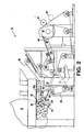
- Fig. 2 illustrates another aspect of the invention in which a lead-in roll 124 is rotatably disposed against the first felt conveyor 20 a predetermined distance from the dryer 12 such that draw D is formed between the dryer 12 and the lead-in roll 124.
- the lead-in roll 124 cooperates with the first felt conveyor 20 to transfer the advancing web 18 from the dryer 12 in a direction toward the overlap area 32.
- the lead-in roll 124 may have at least one circumferential groove 25 as shown in Fig. 3 to help control boundary layer air in order to assist in the pick-up of web 18 and to hold web 18 on first felt conveyor 20 until web 18 reaches overlap area 32.
- roll 124 with circumferential grooves 25 cooperates with the conveyor 20 to thread web 18 from the dryer 12 across draw D to first conveyor 20.
- tissue or web 18 can be doctored off dryer 12 and drawn by gravity at known web speeds or blown onto conveyor 20, which supports and carries the web 18 to the overlap area 32.
- an air plenum. 33 may be provided to blow air A in the direction of the felt conveyors 20 and 30 to help to ensure the transfer of web 18 across the draw D to conveyor 20 and towards conveyor 30.
- a lead-in vacuum box 26 may be disposed adjacent the lead-in roll 124 as seen in Fig. 2 .
- the lead-in roll 124 is thus disposed substantially between the dryer 12 and the lead-in vacuum, box 26.
- the lead-in vacuum box 26 may be configured to attract the web 18 by suction force to the first felt conveyor 20 as the first felt conveyor 20 passes over the lead-in roll 124.
- box 26 may also be a static induction device or any combination of web attraction devices to attract web 18 to lead-in roll 124 toward overlap area 32.
- the exemplary embodiment of Fig. 2 can include one or more web attraction devices, such as vacuum box 34, blow box 134, or static induction device 234, as alluded to in the foregoing embodiment.
- the vacuum box 34 is configured to help to maintain the lightweight web 18 against second conveyor 30 until web 18 reaches the reel spool 37 for wind-up.
- vacuum box 34 may include blow box edges (not shown) or be otherwise configured to blow air substantially perpendicular to a direction of movement of the conveyor 30 to create venturi effects (to cause a drop in pressure) in the vicinity of conveyor 30 and assist in holding web 18 against the conveyor 30.
- web 18 may be held in place by a static induction device 234 in lieu of or in addition to vacuum box 34.
- the vacuum box 34 may also have replaceable plastic wear edges (not shown) to reduce wear on the fabric 20. With this option, plastic (or other suitable material) wear edges can be easily replaced instead of necessitating replacement of conveyor belts 20 due to frequent, rapid contact with edges of the boxes 34.
- boxes 34, 134, 234 are not limited to the examples delineated above nor as shown in the Figures.
- the web attraction devices can be placed at any point along the pick-up conveyor 20 and/or delivery conveyor 30.
- System 10 may further includes an air scoop 38 disposed substantially between the dryer 12 and the lead-in roll 124.
- the air scoop 38 is configured to deflect an air mass (not shown) from a rotation of the dryer 12 in a direction substantially toward the first felt conveyor 20 to further assist in controlled transfer of web 18 to conveyor 20.
- At least one shear-inducing element 128 may be disposed as seen for example in Fig 2 .
- at least one of the first and second felt conveyors 20, 30 is sufficiently wrapped around the at least one shear-inducing element 128 to create shear forces that act upon the web 18 and increase the softness of the web 18.
- This S-wrap configuration may be located at any desired point along conveyors 20, 30 and may include a plurality of such configurations if required.
- Fig. 2 also illustrates another aspect of system 10, which may include at least one device, such as exemplary devices 40 a, b, to apply topical agents to the conveyors 20, 30 to coat the web 18.
- exemplary devices 40 a, b to apply topical agents to the conveyors 20, 30 to coat the web 18.
- two devices 40 a, b are shown, a plurality of such devices may be disposed at various other locations in system 20. Further, additional devices as well as devices 40 a, b may be configured to each apply distinct topical agents as desired.
- Fig. 4 illustrates a further aspect of the present invention in which a system 110 for transferring and reeling a continuously advancing tissue web 18 from dryer 12 to a reel drum 36a until it is wound onto a reel spool 37a.
- a second reel drum 36b may be used in combination with reel drum 36a to assist in winding a parent roll 48.
- the system 110 may have only one conveyor 20, which is positioned downstream from the dryer 12 such that draw D is formed between the conveyor 20 and the dryer 12 in an arrangement similar to the foregoing embodiments. Accordingly, the conveyor 20 is configured to continuously receive the web 18 across the draw D and continuously advance the web 18, in contact with a bottom side 20a of conveyor 20 in the direction of the reel drum 36a located within a conveyor loop formed by conveyor 20.
- a method for transporting the web 18 from the dryer 12 to the reel section 36 comprising the step of continuously advancing the web 18 from the dryer 12 to the first fabric belt 20.
- the first fabric belt 20 may be permeable and is optimally arranged proximate the dryer 12 for picking up the web 18 as described above.
- Further steps may include receiving the web 18 on the first fabric belt 20 by the pick-up point 22, advancing the web 18 on the first fabric belt 20 in the direction of a reel drum 36, guiding the web 18 between the first fabric belt 20 and a permeable second fabric belt 30, threading a continuously advancing leading end portion (not shown) of the web 18 from the second fabric belt 30 onto a reel spool 37 adjacent the reel drum 36, and continuously winding the threaded web 18 into a parent roll (not shown) from the reel spool 37.
- the method may also include the steps of guiding the first fabric belt 20 and the second fabric belt 30 around the at least one shear-inducing element 128 while the web 18 is positioned between the belts 20, 30.
- the first and second belts 20, 30 should be sufficiently wrapped around the at least one shear-inducing element 128 so as to create shear forces that act upon the web 18 to increase the softness of the web 18 as desired by the consumer.
Abstract
Description
- In the manufacture of paper or tissue products such as facial tissues, bath tissues and paper towels, the base sheets are generally produced by depositing an aqueous suspension of paper making fibers onto a forming fabric, dewatering the suspension to form a web, drying the web and winding the dried web into a roll for subsequent conversion into a particular product. During manufacturing, most webs are adhered to a steam heated Yankee dryer and thereafter dislodged from the surface of the Yankee dryer by contact with a doctor blade (creping) prior to winding to improve the softness and stretch of the sheet.
- In some existing processes, the final sheet traverses an "open draw" before being wound into rolls. Accordingly, the dried sheet is momentarily unsupported before being wound. In the case of creped tissue sheets, the sheet is dislodged from the creping cylinder and passed unsupported from the creping cylinder to a reel. This is true for both creped conventional (wet pressed) or creped through air dried (TAD) sheets. In addition, it is envisioned that this process could be utilized on a sheet that is not creped, similar to machine glazed (MG) grades. As known in the tissue manufacturing business, these unsupported runs or open draws are a source of sheet breaks and production delay time. To compensate, the tissue paper sheets are designed to have high strengths, particularly in the machine direction, in order to remain intact during manufacturing. However, high tissue strengths may negatively impact tissue softness, which is not desirable to the consumer.
- The present invention provides a method and apparatus for transporting a sheet from a Yankee dryer, for example, to a reel, which advantageously leverages the open draw between the dryer and the reel. In so doing, tissue sheets having lower machine direction strength can be made such that the tissue sheets are softer and more substantially square shaped in terms of the machine direction and cross machine direction tensile strengths.
- According to an aspect of the invention, a system for transferring a continuously advancing paper web from a dryer to a reel section is disclosed. The system has a first felt or fabric, which defines a first moving conveyor (herein, first fabric) and a second felt or fabric defining a second moving conveyor (herein, second fabric). The first fabric is positioned downstream from the dryer and may overlap the second fabric for a predetermined distance to receive the paper web between the fabrics. Ideally, the fabrics are permeable fabrics, which may have the same - but more typically - disparate levels of permeability. Permeable fabrics contemplated by the invention generally exhibit air flow in the range of 50-700 cubic feet per minute (cfm) at 125 pascals pressure drop when the fabrics are new.
- The system for transferring the web may also include a vacuum device rotatably disposed against the first fabric. The vacuum device and the dryer may be arranged to form an open draw relative to each other. Optimally, the vacuum device is configured to produce a suction to attract the web to the first fabric for transferring the advancing web into the predetermined distance where the first and second fabric overlap. Further, a reel may be rotatably disposed against the second fabric. If desired, the reel and the second fabric can cooperate to advance the web to a reel spool for winding.
- Optimally, a vacuum box may be provided for holding the web against the second fabric. If provided, the vacuum box is disposed adjacent the second fabric. Alternatively, a blow box for holding the web can be substituted for or supplement the vacuum box. Likewise, a static induction device can be used for holding the web in place on the fabrics.
- According to another aspect of the invention, a system for transferring the advancing web from the dryer to the reel section can comprise a first felt conveyor or pick-up fabric conveyor configured to receive the web from the dryer at a pick-up point on the first felt. A delivery or second felt conveyor ideally overlaps the first felt conveyor at an overlap area disposed apart from the pick-up point. The first and second felt conveyors receive the web between the conveyors in the overlap area.
- In this aspect, a lead-in roll is rotatably disposed against the first felt conveyor at a predetermined distance from the dryer such that a draw similar to that described above is formed between the dryer and the lead-in roll. The lead-in roll cooperates with the first felt conveyor to transfer the advancing web from the dryer in a direction toward the overlap area. Also, a reel is rotatably disposed against the second felt conveyor. The reel and the second felt conveyor cooperate to advance the web to a reel spool for winding the web.
- The system may include a lead-in vacuum box located near the lead-in roll. In this case, the lead-in roll is disposed substantially between the dryer and the lead-in vacuum box, and the lead-in vacuum box suctions the web to the first felt conveyor as the first felt conveyor passes over the lead-in roll. If desired, an air scoop may be disposed substantially between the dryer and the lead-in roll to deflect an air mass from the dryer in a direction substantially toward the first felt conveyor. Additionally, a second vacuum box can be provided adjacent the second felt conveyor in the vicinity of the reel in a direction away from the lead-in roll.
- According to another aspect of the invention, a method is disclosed for transporting the web from the dryer to the reel section. The method may include the steps of continuously advancing the web from the dryer to a first fabric belt. The first fabric belt may be arranged to run across a device located near the dryer for picking up the web. The method may include the substeps of receiving the web on the first fabric belt by the pick-up device, advancing the web on the first fabric belt in the direction of a reel drum, guiding the web between the first fabric belt and a second fabric belt, threading a continuously advancing leading end portion of the web from the second fabric belt onto a reel spool adjacent the reel drum and continuously winding the threaded web into a parent roll from the reel spool. If desired the method may also include the steps of guiding the first fabric belt and the second fabric belt around at least one shear-inducing element while the web is positioned between the belts. Ideally, the first and second belts should be sufficiently wrapped around the at least one shear-inducing element to create shear forces to act upon the web and increase the softness of the web.
- The above and other aspects and advantages of the present invention are apparent from the detailed description below in combination with the drawings in which:
-
Fig. 1 is a schematic diagram of an aspect of the invention illustrating an open draw between a dryer and a lead-in roll; -
Fig. 2 is a schematic diagram of an alternative aspect of the invention; -
Fig. 3 is a front view of an optional grooved lead-in roll taken along line III-III inFig. 2 ; and -
Fig. 4 is a schematic diagram of another alternative aspect of the invention. - Repeat use of reference characters in the present specification and drawings is intended to represent the same or analogous features or elements of the present invention.
- Detailed reference will now be made to the drawings in which examples embodying the present invention are shown. The drawings and detailed description provide a full and detailed written description of the invention, and of the manner and process of making and using it, so as to enable one skilled in the pertinent art to make and use it, as well as the best mode of carrying out the invention. However, the examples set forth in the drawings and detailed description are provided by way of explanation of the invention and are not meant as limitations of the invention. The present invention thus includes any modifications and variations of the following examples as come within the scope of the appended claims and their equivalents.
- As broadly embodied in the Figures, a system for transferring a continuously advancing paper web from a dryer to a reel section is provided. In general, a
transfer system 10 is shown with a dryer, for example, a Yankeedryer 12, a creping station ordoctor 14, a first fabric 20 (alternatively a first felt conveyor, first fabric belt or pick-up fabric conveyor), a second fabric 30 (alternatively second felt conveyor, delivery conveyor, second fabric felt) and areel 36 ordrum 36. - While
Figures 1 and2 illustrate system 10 having a plurality ofconveyor rolls 28,vacuum boxes belts - Further, it is to be noted that
first fabric 20 andsecond fabric 30 may be permeable fabrics having the same permeability; more likely, however,first fabric 20 andsecond fabric 30 have different permeabilities. Also, the permeabilities of thefabrics system 10 due to repeated web W contact withfabrics fabrics - With more particular reference to the Figures, the Yankee
dryer 12 is shown inFig. 1 delivering theweb 18 to thecreping station 14 and across a draw D to avacuum roll 24. In an optimal arrangement, thefirst fabric belt 20 is located adjacent thesecond fabric belt 30 such that thefirst fabric belt 20 picks up theweb 18 at a pick-up point 22 and delivers theweb 18 in the direction of thesecond fabric belt 30. Theweb 18 continues in a direction of thereel 36 first through anoverlap area 32 disposed betweenfirst fabric 20 andsecond fabric 30, both of which may be a screen, a fabric or the like. Theweb 18 continues in the direction of the optional vacuum box(es) 34a, 34b and acrossreel 36 until it is wound onto areel spool 37.Reel spool 37 may be a spool, a spool with a core, or a coreless system around which aweb 18 winds. It is also contemplated thatreel spool 37 may be arranged elsewhere onsystem 10, such as in a position of reel spool 37', as required. -
Fig. 1 further shows an aspect of the invention in whichfirst fabric 20 defines a first moving conveyor. Thefirst fabric 20 is positioned downstream from thedryer 12 and is configured to pick-up and move theweb 18 towards thesecond fabric 30 as theweb 18 leaves thecreping station 14. The optional creping station ordoctor 14 separates and deflects theweb 18 from thedryer 12 to thefirst fabric 20. For instance,Fig. 1 and2 illustrate that atransfer plenum 16 may doctor off theweb 18 from a surface of thedryer 12 by thetransfer plenum 16 riding close to adryer surface 12a. Thedoctor 14/transfer plenum 16 are optimally designed to divert and control boundary layer air to promote a smooth tissue orweb 18 transition to thefirst fabric 20. - The
second fabric 30 defines a second moving conveyor. The second movingconveyor 30 is overlapped by the first movingconveyor 20 as shown inFig. 1 for apredetermined distance 32. Theoverlap area 32 ideally extends partially along bothconveyors Figs. 1 and2 but theoretically could run from substantially near the pick-uppoint 22 to thereel 36. Optimally, distance 32 need only be of sufficient length to ensureweb 18 is securely positioned on second movingconveyor 30. Accordingly, the first and second movingconveyors Fig. 1 receive thepaper web 18 between theconveyors reel 36 to hold theweb 18 in place for transfer to reel 36. - In the foregoing example,
vacuum device 24 may again be rotatably disposed against the first movingconveyor 20. Thedryer 12 and thevacuum device 24 are then disposed relative to each other to form open draw D. Thevacuum device 24 is configured to produce a suction force or vacuum, indicated by arrow 24', to attract theweb 18 to thefirst fabric 20 for transferring the advancingweb 18 into thepredetermined distance 32 where the first andsecond conveyors vacuum device 24 may be arranged to form a nip N into which theweb 18 is received after the draw D. - The draw D of
system 10 may have a length of between 4 inches to about 48 inches. Optimally, the open draw D defines a distance of between 10 inches to about 30 inches. The inventors have found that a draw D of approximately one foot advantageously accommodates various elements ofsystem 10 while optimizingweb 18 transfer from thecreping station 14 to thefirst fabric 20 withfewer web 18 breaks. - As shown in
Figure 1 , once theweb 18 reaches the vicinity ofreel 36,web 18 can be held against the second movingconveyor 30 byvacuum boxes lightweight web 18 to hold it securely against theconveyor 30 until it is wound onto the reel spool. By way of example,vacuum boxes blow box 134 or a static induction device 234 (discussed inFig. 2 below) may be provided in lieu of or in addition tovacuum box 34 to reduce or prevent fly-up of outside edges ofweb 18, sinceweb 18 may be a tissue product having a basis weight of about 2 grams per square meter (gsm) to about 65 gsm, or about 25 pounds per ream. -
Fig. 2 illustrates another aspect of the invention in which a lead-inroll 124 is rotatably disposed against the first felt conveyor 20 a predetermined distance from thedryer 12 such that draw D is formed between thedryer 12 and the lead-inroll 124. The lead-inroll 124 cooperates with thefirst felt conveyor 20 to transfer the advancingweb 18 from thedryer 12 in a direction toward theoverlap area 32. If desired, the lead-inroll 124 may have at least onecircumferential groove 25 as shown inFig. 3 to help control boundary layer air in order to assist in the pick-up ofweb 18 and to holdweb 18 onfirst felt conveyor 20 untilweb 18 reaches overlaparea 32. - With more specific reference to the foregoing aspect, roll 124 with circumferential grooves 25 (
Fig. 3 ) cooperates with theconveyor 20 tothread web 18 from thedryer 12 across draw D tofirst conveyor 20. In this aspect, tissue orweb 18 can be doctored offdryer 12 and drawn by gravity at known web speeds or blown ontoconveyor 20, which supports and carries theweb 18 to theoverlap area 32. Optionally, an air plenum. 33 (Fig. 1 ) may be provided to blow air A in the direction of the feltconveyors web 18 across the draw D toconveyor 20 and towardsconveyor 30. - If desired, a lead-in
vacuum box 26 may be disposed adjacent the lead-inroll 124 as seen inFig. 2 . In this example, the lead-inroll 124 is thus disposed substantially between thedryer 12 and the lead-in vacuum,box 26. The lead-invacuum box 26 may be configured to attract theweb 18 by suction force to thefirst felt conveyor 20 as thefirst felt conveyor 20 passes over the lead-inroll 124. As suggested,box 26 may also be a static induction device or any combination of web attraction devices to attractweb 18 to lead-inroll 124 towardoverlap area 32. - The exemplary embodiment of
Fig. 2 can include one or more web attraction devices, such asvacuum box 34,blow box 134, orstatic induction device 234, as alluded to in the foregoing embodiment. By way of specific example, thevacuum box 34 is configured to help to maintain thelightweight web 18 againstsecond conveyor 30 untilweb 18 reaches thereel spool 37 for wind-up. - If desired,
vacuum box 34 may include blow box edges (not shown) or be otherwise configured to blow air substantially perpendicular to a direction of movement of theconveyor 30 to create venturi effects (to cause a drop in pressure) in the vicinity ofconveyor 30 and assist in holdingweb 18 against theconveyor 30. Alternatively,web 18 may be held in place by astatic induction device 234 in lieu of or in addition tovacuum box 34. Thevacuum box 34 may also have replaceable plastic wear edges (not shown) to reduce wear on thefabric 20. With this option, plastic (or other suitable material) wear edges can be easily replaced instead of necessitating replacement ofconveyor belts 20 due to frequent, rapid contact with edges of theboxes 34. - It should be understood that the number and placement of
boxes conveyor 20 and/ordelivery conveyor 30. -
System 10 may further includes anair scoop 38 disposed substantially between thedryer 12 and the lead-inroll 124. Theair scoop 38 is configured to deflect an air mass (not shown) from a rotation of thedryer 12 in a direction substantially toward thefirst felt conveyor 20 to further assist in controlled transfer ofweb 18 toconveyor 20. - In another aspect of the invention, at least one shear-inducing
element 128 may be disposed as seen for example inFig 2 . In this illustration, at least one of the first and second feltconveyors element 128 to create shear forces that act upon theweb 18 and increase the softness of theweb 18. This S-wrap configuration may be located at any desired point alongconveyors -
Fig. 2 also illustrates another aspect ofsystem 10, which may include at least one device, such asexemplary devices 40 a, b, to apply topical agents to theconveyors web 18. Although twodevices 40 a, b are shown, a plurality of such devices may be disposed at various other locations insystem 20. Further, additional devices as well asdevices 40 a, b may be configured to each apply distinct topical agents as desired. -
Fig. 4 illustrates a further aspect of the present invention in which asystem 110 for transferring and reeling a continuously advancingtissue web 18 fromdryer 12 to a reel drum 36a until it is wound onto a reel spool 37a. A second reel drum 36b may be used in combination with reel drum 36a to assist in winding aparent roll 48. Thesystem 110 may have only oneconveyor 20, which is positioned downstream from thedryer 12 such that draw D is formed between theconveyor 20 and thedryer 12 in an arrangement similar to the foregoing embodiments. Accordingly, theconveyor 20 is configured to continuously receive theweb 18 across the draw D and continuously advance theweb 18, in contact with a bottom side 20a ofconveyor 20 in the direction of the reel drum 36a located within a conveyor loop formed byconveyor 20. - According to another aspect of the invention, a method is disclosed for transporting the
web 18 from thedryer 12 to thereel section 36 comprising the step of continuously advancing theweb 18 from thedryer 12 to thefirst fabric belt 20. Thefirst fabric belt 20 may be permeable and is optimally arranged proximate thedryer 12 for picking up theweb 18 as described above. Further steps may include receiving theweb 18 on thefirst fabric belt 20 by the pick-uppoint 22, advancing theweb 18 on thefirst fabric belt 20 in the direction of areel drum 36, guiding theweb 18 between thefirst fabric belt 20 and a permeablesecond fabric belt 30, threading a continuously advancing leading end portion (not shown) of theweb 18 from thesecond fabric belt 30 onto areel spool 37 adjacent thereel drum 36, and continuously winding the threadedweb 18 into a parent roll (not shown) from thereel spool 37. - The method may also include the steps of guiding the
first fabric belt 20 and thesecond fabric belt 30 around the at least one shear-inducingelement 128 while theweb 18 is positioned between thebelts second belts element 128 so as to create shear forces that act upon theweb 18 to increase the softness of theweb 18 as desired by the consumer. - It will be apparent to those skilled in the art that various modifications and variations can be made in the present invention without departing from the scope and spirit of the invention. For example, specific shapes, quantities, and arrangements of various elements of the illustrated embodiments may be altered to suit particular applications. It is intended that the present invention include such modifications and variations as come within the scope of the appended claims and their equivalents.
Claims (14)
- A system (10) for transferring an advancing web (18) from a dryer (12) to a reel section (37) comprising:a first felt conveyor (20) configured to receive the web (18) from the dryer (12) at a pick-up point (22) on the first felt conveyor (20);a second felt conveyor (30) overlapping the first felt conveyor (20) at an overlap area (32) disposed apart from the pick-up point (22), the first and second felt conveyors (20,30) being configured to receive the web (18) between the conveyors proximate the overlap area (32); anda lead-in roll (124) rotatably disposed against the first felt conveyor (20) a predetermined distance from the dryer (12) such that a draw (D) is formed between the dryer (12) and the lead-in roll (124), the lead-in roll (124) cooperative with the first felt conveyor (20) such that the advancing web (18) is transferred from the dryer (12) in a direction toward the overlap area (32).
- The system of Claim 1, where in the lead-in roll (124) has at least one groove (25).
- The system as in Claim 1, further comprising a lead-in vacuum box (26) disposed adjacent the lead-in roll (124), the lead-in roll (124) disposed substantially between the dryer (12) and the lead-in vacuum box (26), the lead-in vacuum box (26) configured to suctionally attract the web (18) to the first felt conveyor (20) as the first felt conveyor (20) passes over the lead-in roll (124).
- The system as in Claim 1, further comprising an air scoop (38) disposed substantially between the dryer (12) and the lead-in roll (124), the air scoop (38) configured to deflect an air mass from the dryer (12) in a direction substantially toward the first felt conveyor (20).
- The system as in Claim 1, further comprising a second vacuum box (34) disposed adjacent the second felt conveyor (30) proximate a reel (36) in a direction away from the lead-in roll (124), the reel (36) rotatably disposed against the second felt conveyor (30), the reel (36) and the second felt conveyor (30) cooperating to advance the web (18) to a reel spool (37) for winding the web (18).
- A system for transferring a continuously advancing tissue web from a dryer to a reel section comprising:a first permeable conveyor positioned downstream from the dryer, the first permeable conveyor configured to continuously move the web;a second permeable conveyor configured to continuously move the web, the first permeable conveyor overlapping the second permeable conveyor for a predetermined distance, the first and second permeable conveyors being configured to receive the tissue web between the conveyors; anda web attraction device disposed proximate the first permeable conveyor and further disposed relative to the dryer to form an open draw therebetween, the web attraction device configured to attract the web to the first permeable conveyor for transferring the advancing web into the predetermined distance where the first and second permeable conveyors overlap.
- The system of Claim 6, further comprising means for coating the web.
- The system of Claim 7, wherein the means for coating is at least one of the first and second permeable conveyors, the at least one of the first and second permeable conveyors configured to add a topical agent to the web.
- A system for transporting an advancing paper web comprising:a pick-up fabric conveyor configured to receive and transport the web across an open draw between a dryer and the pick-up fabric conveyor;a delivery conveyor disposed in partial moving engagement with the pick-up fabric conveyor along a length of each of the delivery and pick-up fabric conveyors, the delivery and pick-up fabric conveyors being configured to receive the web between the conveyors; andtransferring means for transferring the web from the draw to the pick-up fabric conveyor, the transferring means disposed against the pick-up fabric conveyor and at least partially between the dryer and the delivery conveyor, the transferring means cooperative with the pick-up fabric conveyor for transferring the advancing web from the pick-up fabric conveyor to between the conveyors in the direction of a reel assembly.
- A method for transporting a web from a dryer to a reel section comprising the steps of:continuously advancing the web from the dryer to a first fabric belt, the first fabric belt arranged to run across pick-up means disposed proximate the dryer for picking up the web;receiving the web on the first fabric belt by the pick-up means;advancing the web on the first fabric belt in a direction of a downstream reel spool;guiding the web between the first fabric belt and a second fabric belt;threading a continuously advancing leading end portion of the web from the second fabric belt onto the reel spool adjacent a reel drum; andcontinuously winding the threaded web into a parent roll on the reel spool.
- The method of Claim 10, further comprising the step of continuously creping the web as the web advances from the dryer to the first fabric belt.
- The method of Claim 10, wherein the web is a tissue product having a basis weight of between about 2 grams per square meter (gsm) to about 65 gsm.
- A system for transferring and reeling a continuously advancing tissue web from a dryer to a reel section comprising a conveyor positioned downstream from the dryer such that an open draw is formed between the conveyor and the dryer, the conveyor configured to continuously receive the web across the draw and continuously advance the web along a bottom side of the conveyor in a direction of a reel drum located within a conveyor loop.
- The system of claim 13, further comprising a pick-up device disposed proximate the draw and the conveyor, the pick-up device configured to attract the web to the conveyor for transferring the advancing web to the reel section.
Applications Claiming Priority (2)
| Application Number | Priority Date | Filing Date | Title |
|---|---|---|---|
| US10/025,205 US7001487B2 (en) | 2001-12-19 | 2001-12-19 | Method and apparatus for transporting a sheet from a dryer to a reel |
| EP02782366A EP1456466B1 (en) | 2001-12-19 | 2002-11-21 | Method and apparatus for transporting a sheet from a dryer to a reel |
Related Parent Applications (2)
| Application Number | Title | Priority Date | Filing Date |
|---|---|---|---|
| EP02782366.5 Division | 2002-11-21 | ||
| EP02782366A Division EP1456466B1 (en) | 2001-12-19 | 2002-11-21 | Method and apparatus for transporting a sheet from a dryer to a reel |
Publications (3)
| Publication Number | Publication Date |
|---|---|
| EP1939353A2 true EP1939353A2 (en) | 2008-07-02 |
| EP1939353A3 EP1939353A3 (en) | 2008-10-29 |
| EP1939353B1 EP1939353B1 (en) | 2011-11-16 |
Family
ID=21824647
Family Applications (2)
| Application Number | Title | Priority Date | Filing Date |
|---|---|---|---|
| EP08000215A Expired - Lifetime EP1939353B1 (en) | 2001-12-19 | 2002-11-21 | Method and apparatus for transporting a sheet from a dryer to a reel |
| EP02782366A Expired - Lifetime EP1456466B1 (en) | 2001-12-19 | 2002-11-21 | Method and apparatus for transporting a sheet from a dryer to a reel |
Family Applications After (1)
| Application Number | Title | Priority Date | Filing Date |
|---|---|---|---|
| EP02782366A Expired - Lifetime EP1456466B1 (en) | 2001-12-19 | 2002-11-21 | Method and apparatus for transporting a sheet from a dryer to a reel |
Country Status (12)
| Country | Link |
|---|---|
| US (3) | US7001487B2 (en) |
| EP (2) | EP1939353B1 (en) |
| JP (1) | JP4356981B2 (en) |
| KR (1) | KR100954009B1 (en) |
| AT (2) | ATE533892T1 (en) |
| AU (1) | AU2002348237B2 (en) |
| BR (1) | BR0214711A (en) |
| CA (1) | CA2469122C (en) |
| DE (1) | DE60226897D1 (en) |
| MX (1) | MXPA04005243A (en) |
| TW (1) | TW593102B (en) |
| WO (1) | WO2003054296A1 (en) |
Families Citing this family (15)
| Publication number | Priority date | Publication date | Assignee | Title |
|---|---|---|---|---|
| US7001487B2 (en) * | 2001-12-19 | 2006-02-21 | Kimberly-Clark Worldwide, Inc. | Method and apparatus for transporting a sheet from a dryer to a reel |
| FI112677B (en) * | 2002-02-25 | 2003-12-31 | Metso Paper Inc | Method and apparatus for feeding a feeding tip, especially in a paper machine |
| US6797115B2 (en) * | 2002-03-29 | 2004-09-28 | Metso Paper Karlstad Ab | Method and apparatus for making a creped tissue with improved tactile qualities while improving handling of the web |
| US20040259750A1 (en) * | 2002-04-22 | 2004-12-23 | The Procter & Gamble Company | Processes and apparatuses for applying a benefit composition to one or more fabric articles during a fabric enhancement operation |
| US6743334B2 (en) * | 2002-06-11 | 2004-06-01 | Metso Paper Karlstad Aktiebolag (Ab) | Method and apparatus for making a tissue paper with improved tactile qualities while improving the reel-up process for a high bulk web |
| DE10326304A1 (en) * | 2003-06-11 | 2005-02-03 | Voith Fabrics Patent Gmbh | Method and device for producing a tissue web |
| AT413709B (en) * | 2004-06-28 | 2006-05-15 | Andritz Ag Maschf | DEVICE FOR CONTINUOUS DRYING OF A FIBROUS WEB |
| US7398943B2 (en) * | 2005-06-24 | 2008-07-15 | Kimberly-Clark Worldwide, Inc. | Apparatus for winding paper with static control |
| US7661622B2 (en) | 2005-09-30 | 2010-02-16 | Kimberly-Clark Worldwide, Inc. | Apparatus and method for winding and transporting paper |
| US20080179775A1 (en) * | 2007-01-31 | 2008-07-31 | Usg Interiors, Inc. | Transfer Plate Useful in the Manufacture of Panel and Board Products |
| SE537959C2 (en) | 2013-03-27 | 2015-12-08 | Valmet Aktiebolag | Wheelchair and method for rolling up a paper web from the edge of a paper machine |
| US8939445B2 (en) * | 2013-05-30 | 2015-01-27 | Kimberly-Clark Worldwide, Inc. | Vacuum roll with internal rotary valve |
| DE102015001008A1 (en) * | 2015-01-28 | 2016-07-28 | Andritz Küsters Gmbh | Process and apparatus for the production of wetlaid nonwovens |
| WO2018044814A1 (en) | 2016-08-31 | 2018-03-08 | Kimberly-Clark Worldwide, Inc. | Web winding device |
| CN111713721A (en) * | 2020-05-19 | 2020-09-29 | 安徽维斯达食品机械有限公司 | Food paper padding machine |
Citations (7)
| Publication number | Priority date | Publication date | Assignee | Title |
|---|---|---|---|---|
| US1842889A (en) * | 1928-09-01 | 1932-01-26 | Harrison R Williams | Paper machinery |
| US4087319A (en) * | 1976-12-27 | 1978-05-02 | Beloit Corporation | Method of and means for sheet transfer to and embossing at a reeling station |
| US4728396A (en) * | 1986-12-02 | 1988-03-01 | Beloit Corp. | Method of operating and threading a coater |
| DE3924897A1 (en) * | 1989-07-27 | 1991-02-07 | Escher Wyss Gmbh | Leader transfer - has swing jet mechanism to separate leader from roller and transfer it to onwards cable conveyor |
| US5037509A (en) * | 1990-10-29 | 1991-08-06 | Beloit Corporation | Apparatus for transferring a threading tail of a web |
| US5241760A (en) * | 1987-02-13 | 1993-09-07 | Beloit Technologies, Inc. | Dryer apparatus |
| DE19747835A1 (en) * | 1997-10-22 | 1999-04-29 | Joerg Parzsch | Device is for guiding and severing pointed paper end |
Family Cites Families (54)
| Publication number | Priority date | Publication date | Assignee | Title |
|---|---|---|---|---|
| GB717251A (en) * | 1952-01-12 | 1954-10-27 | Ralph Chalinor Heys | Improvements in or relating to the manufacture of paper and to paper-making machines |
| US2857222A (en) * | 1956-01-24 | 1958-10-21 | Jean Rea | Table and room divider |
| US3072522A (en) * | 1958-10-27 | 1963-01-08 | Beloit Iron Works | Reconstituted creped paper and method and apparatus for making same |
| US3432936A (en) * | 1967-05-31 | 1969-03-18 | Scott Paper Co | Transpiration drying and embossing of wet paper webs |
| US3855057A (en) * | 1967-11-02 | 1974-12-17 | Beloit Corp | Paper formation utilizing a large diameter suction roll |
| FI284474A (en) * | 1974-09-27 | 1976-03-28 | Valmet Oy | |
| US4036684A (en) * | 1975-08-04 | 1977-07-19 | Beloit Corporation | High bulk tissue forming and drying apparatus |
| AT355417B (en) | 1977-04-26 | 1980-03-10 | Escher Wyss Gmbh | WINDING DEVICE FOR PAPER MACHINES |
| AT363321B (en) | 1978-03-22 | 1981-07-27 | Escher Wyss Gmbh | WINDING DEVICE FOR PAPER MACHINES |
| US4175714A (en) | 1978-05-18 | 1979-11-27 | Beloit Corporation | Method and apparatus for reeling a plurality of ribbons |
| US4726502A (en) | 1986-07-07 | 1988-02-23 | Cryderman Gary G | Apparatus for entraining and directing a wet paper web |
| US4943351A (en) * | 1988-05-23 | 1990-07-24 | Beloit Corporation | Transfer apparatus and method |
| US5127168A (en) * | 1989-07-20 | 1992-07-07 | Pulp And Paper Research Institute Of Canada | Method for manufacture of smooth and glossy papers and apparatus |
| US5545295A (en) * | 1991-09-04 | 1996-08-13 | Mitsubishi Jukogyo Kabushiki Kaisha | Web transfer device |
| DK0656970T3 (en) | 1992-08-27 | 1997-11-03 | Procter & Gamble | Tissuepair treated with non-ionic plasticizers that are biodegradable |
| US5336373A (en) * | 1992-12-29 | 1994-08-09 | Scott Paper Company | Method for making a strong, bulky, absorbent paper sheet using restrained can drying |
| US5667636A (en) * | 1993-03-24 | 1997-09-16 | Kimberly-Clark Worldwide, Inc. | Method for making smooth uncreped throughdried sheets |
| US5607551A (en) | 1993-06-24 | 1997-03-04 | Kimberly-Clark Corporation | Soft tissue |
| JP3320852B2 (en) * | 1993-08-02 | 2002-09-03 | 株式会社名南製作所 | Sheet-like article sorting device |
| JPH07113196A (en) * | 1993-10-13 | 1995-05-02 | Nippon Steel Corp | Method for preventing wire flaw in plated metallic body |
| FI94231C (en) | 1993-12-16 | 1995-08-10 | Valmet Paper Machinery Inc | Method and apparatus for winding a web of paper or paperboard in a pope winder or the like |
| US5695607A (en) * | 1994-04-01 | 1997-12-09 | James River Corporation Of Virginia | Soft-single ply tissue having very low sidedness |
| US5591309A (en) | 1995-02-06 | 1997-01-07 | Kimberly-Clark Corporation | Papermaking machine for making uncreped throughdried tissue sheets |
| US5593545A (en) | 1995-02-06 | 1997-01-14 | Kimberly-Clark Corporation | Method for making uncreped throughdried tissue products without an open draw |
| WO1997001671A1 (en) | 1995-06-28 | 1997-01-16 | The Procter & Gamble Company | Creped tissue paper exhibiting unique combination of physical attributes |
| US5891308A (en) * | 1996-02-02 | 1999-04-06 | Beloit Technologies, Inc. | Method of pressing a paper web of tropical hardwood fibers |
| US5853547A (en) * | 1996-02-29 | 1998-12-29 | Asten, Inc. | Papermaking fabric, process for producing high bulk products and the products produced thereby |
| US5944954A (en) * | 1996-05-22 | 1999-08-31 | The Procter & Gamble Company | Process for creping tissue paper |
| SE507509C2 (en) | 1996-10-21 | 1998-06-15 | Valmet Karlstad Ab | Wheelchair with double secondary units for rolling up a running track in a paper machine |
| US5875990A (en) | 1996-12-16 | 1999-03-02 | Valmet-Karlstad Ab | Reel-up |
| US5762759A (en) * | 1997-01-27 | 1998-06-09 | Beloit Technologies, Inc. | Tail threading system for a papermaking machine |
| FI106248B (en) | 1997-02-13 | 2000-12-29 | Valmet Corp | Rolling machine and method of rolling up paper web or equivalent |
| US5851353A (en) * | 1997-04-14 | 1998-12-22 | Kimberly-Clark Worldwide, Inc. | Method for wet web molding and drying |
| SE509107C2 (en) | 1997-04-21 | 1998-12-07 | Valmet Karlstad Ab | Wheelchair with double secondary units |
| AU3256197A (en) | 1997-06-02 | 1998-12-21 | Beloit Technologies, Inc. | Method and apparatus for reeling a traveling paper web |
| CA2208381A1 (en) | 1997-06-20 | 1998-12-20 | Roman C. Caspar | Apparatus for cutting and threading a tail of a travelling web in a papermaking machine |
| US5901918A (en) | 1997-07-03 | 1999-05-11 | Valmet-Karlstad Ab | Apparatus and method for winding paper |
| US5944273A (en) | 1997-07-03 | 1999-08-31 | Kimberly-Clark Worldwide, Inc. | Parent roll for tissue paper |
| US5988030A (en) | 1997-09-19 | 1999-11-23 | Kimberly-Clark Worldwide, Inc. | Apparatus for penetrating a sheet material web carried on a fabric |
| US6131784A (en) * | 1997-12-22 | 2000-10-17 | Valmet-Karlstad Ab | Threading device |
| US6187140B1 (en) * | 1997-12-31 | 2001-02-13 | Kimberly-Clark Worldwide, Inc. | Creping process utilizing low temperature-curing adhesive |
| DE19848816A1 (en) | 1998-10-22 | 2000-04-27 | Voith Sulzer Papiertech Patent | Winding machine |
| US6183601B1 (en) | 1999-02-03 | 2001-02-06 | Kimberly-Clark Worldwide, Inc. | Method of calendering a sheet material web carried by a fabric |
| FI990956A0 (en) | 1999-04-28 | 1999-04-28 | Valmet Corp | Procedure for continuous rewinding of a paper web and wheelchair |
| KR20010055660A (en) * | 1999-12-11 | 2001-07-04 | 이구택 | Device for supplying paper of sheet shear |
| US6669818B2 (en) * | 2000-06-28 | 2003-12-30 | Metso Paper Karlstad Ab | Shortened layout from dryer to reel in tissue machine |
| US6749723B2 (en) * | 2000-06-28 | 2004-06-15 | Metso Paper Karlstad Ab | Measuring arrangements in a shortened dry end of a tissue machine |
| US6558514B2 (en) * | 2001-01-12 | 2003-05-06 | Valmet, Inc. | Web support and transferring a paper web between papermachine components |
| US20030183353A1 (en) * | 2001-12-10 | 2003-10-02 | Metso Paper Karlstad Ab | Press section tail threading |
| US7001487B2 (en) * | 2001-12-19 | 2006-02-21 | Kimberly-Clark Worldwide, Inc. | Method and apparatus for transporting a sheet from a dryer to a reel |
| US6626428B2 (en) * | 2001-12-28 | 2003-09-30 | Kabushiki Kaisha Toshiba | Sheet ejection mechanism |
| FI112677B (en) * | 2002-02-25 | 2003-12-31 | Metso Paper Inc | Method and apparatus for feeding a feeding tip, especially in a paper machine |
| US6797115B2 (en) * | 2002-03-29 | 2004-09-28 | Metso Paper Karlstad Ab | Method and apparatus for making a creped tissue with improved tactile qualities while improving handling of the web |
| US7888128B2 (en) * | 2003-08-13 | 2011-02-15 | Chem Treat, Inc. | Method for determining surfactant concentration in aqueous solutions |
-
2001
- 2001-12-19 US US10/025,205 patent/US7001487B2/en not_active Expired - Lifetime
-
2002
- 2002-11-21 AU AU2002348237A patent/AU2002348237B2/en not_active Ceased
- 2002-11-21 EP EP08000215A patent/EP1939353B1/en not_active Expired - Lifetime
- 2002-11-21 DE DE60226897T patent/DE60226897D1/en not_active Expired - Lifetime
- 2002-11-21 CA CA2469122A patent/CA2469122C/en not_active Expired - Fee Related
- 2002-11-21 KR KR1020047008464A patent/KR100954009B1/en not_active IP Right Cessation
- 2002-11-21 JP JP2003554989A patent/JP4356981B2/en not_active Expired - Fee Related
- 2002-11-21 WO PCT/US2002/037661 patent/WO2003054296A1/en active Application Filing
- 2002-11-21 BR BRPI0214711-4A patent/BR0214711A/en not_active IP Right Cessation
- 2002-11-21 EP EP02782366A patent/EP1456466B1/en not_active Expired - Lifetime
- 2002-11-21 AT AT08000215T patent/ATE533892T1/en active
- 2002-11-21 MX MXPA04005243A patent/MXPA04005243A/en active IP Right Grant
- 2002-11-21 AT AT02782366T patent/ATE397124T1/en not_active IP Right Cessation
- 2002-12-05 TW TW091135249A patent/TW593102B/en not_active IP Right Cessation
-
2005
- 2005-02-09 US US11/054,026 patent/US7311805B2/en not_active Expired - Fee Related
-
2006
- 2006-05-04 US US11/417,848 patent/US7807024B2/en not_active Expired - Fee Related
Patent Citations (7)
| Publication number | Priority date | Publication date | Assignee | Title |
|---|---|---|---|---|
| US1842889A (en) * | 1928-09-01 | 1932-01-26 | Harrison R Williams | Paper machinery |
| US4087319A (en) * | 1976-12-27 | 1978-05-02 | Beloit Corporation | Method of and means for sheet transfer to and embossing at a reeling station |
| US4728396A (en) * | 1986-12-02 | 1988-03-01 | Beloit Corp. | Method of operating and threading a coater |
| US5241760A (en) * | 1987-02-13 | 1993-09-07 | Beloit Technologies, Inc. | Dryer apparatus |
| DE3924897A1 (en) * | 1989-07-27 | 1991-02-07 | Escher Wyss Gmbh | Leader transfer - has swing jet mechanism to separate leader from roller and transfer it to onwards cable conveyor |
| US5037509A (en) * | 1990-10-29 | 1991-08-06 | Beloit Corporation | Apparatus for transferring a threading tail of a web |
| DE19747835A1 (en) * | 1997-10-22 | 1999-04-29 | Joerg Parzsch | Device is for guiding and severing pointed paper end |
Also Published As
| Publication number | Publication date |
|---|---|
| CA2469122A1 (en) | 2003-07-03 |
| KR100954009B1 (en) | 2010-04-20 |
| TW593102B (en) | 2004-06-21 |
| US7001487B2 (en) | 2006-02-21 |
| KR20040061020A (en) | 2004-07-06 |
| DE60226897D1 (en) | 2008-07-10 |
| EP1939353A3 (en) | 2008-10-29 |
| AU2002348237A1 (en) | 2003-07-09 |
| EP1939353B1 (en) | 2011-11-16 |
| TW200302199A (en) | 2003-08-01 |
| AU2002348237B2 (en) | 2007-11-29 |
| US7311805B2 (en) | 2007-12-25 |
| JP2005535791A (en) | 2005-11-24 |
| EP1456466A1 (en) | 2004-09-15 |
| WO2003054296A1 (en) | 2003-07-03 |
| CA2469122C (en) | 2011-09-20 |
| ATE397124T1 (en) | 2008-06-15 |
| US20060201648A1 (en) | 2006-09-14 |
| MXPA04005243A (en) | 2004-10-11 |
| ATE533892T1 (en) | 2011-12-15 |
| JP4356981B2 (en) | 2009-11-04 |
| BR0214711A (en) | 2006-11-14 |
| EP1456466B1 (en) | 2008-05-28 |
| US7807024B2 (en) | 2010-10-05 |
| US20030111199A1 (en) | 2003-06-19 |
| US20050145743A1 (en) | 2005-07-07 |
Similar Documents
| Publication | Publication Date | Title |
|---|---|---|
| US7311805B2 (en) | System for transferring an advancing web from a dryer across a draw to a reel section | |
| EP1975315B1 (en) | System for manufacturing a web product | |
| US6698681B1 (en) | Apparatus and method for winding paper | |
| EP1919809B1 (en) | Apparatus for winding paper with static control | |
| PL112486B1 (en) | Paper-making machine | |
| CN101374998B (en) | Method and device in a dryer section of a fibre-web machine, such as a paper or board machine | |
| JPH09505518A (en) | Assembly for paper web coating line | |
| EP1341963B1 (en) | Method for modifying an uncreped throughdried tissue sheet | |
| US6235156B1 (en) | Method for paper web transfer and transfer apparatus for paper web | |
| EP1544350A1 (en) | Paper making machine |
Legal Events
| Date | Code | Title | Description |
|---|---|---|---|
| PUAI | Public reference made under article 153(3) epc to a published international application that has entered the european phase |
Free format text: ORIGINAL CODE: 0009012 |
|
| AC | Divisional application: reference to earlier application |
Ref document number: 1456466 Country of ref document: EP Kind code of ref document: P |
|
| AK | Designated contracting states |
Kind code of ref document: A2 Designated state(s): AT BE BG CH CY CZ DE DK EE ES FI FR GB GR IE IT LI LU MC NL PT SE SK TR |
|
| PUAL | Search report despatched |
Free format text: ORIGINAL CODE: 0009013 |
|
| AK | Designated contracting states |
Kind code of ref document: A3 Designated state(s): AT BE BG CH CY CZ DE DK EE ES FI FR GB GR IE IT LI LU MC NL PT SE SK TR |
|
| 17P | Request for examination filed |
Effective date: 20081201 |
|
| 17Q | First examination report despatched |
Effective date: 20090304 |
|
| AKX | Designation fees paid |
Designated state(s): AT BE BG CH CY CZ DE DK EE ES FI FR GB GR IE IT LI LU MC NL PT SE SK TR |
|
| GRAP | Despatch of communication of intention to grant a patent |
Free format text: ORIGINAL CODE: EPIDOSNIGR1 |
|
| GRAS | Grant fee paid |
Free format text: ORIGINAL CODE: EPIDOSNIGR3 |
|
| GRAA | (expected) grant |
Free format text: ORIGINAL CODE: 0009210 |
|
| AC | Divisional application: reference to earlier application |
Ref document number: 1456466 Country of ref document: EP Kind code of ref document: P |
|
| AK | Designated contracting states |
Kind code of ref document: B1 Designated state(s): AT BE BG CH CY CZ DE DK EE ES FI FR GB GR IE IT LI LU MC NL PT SE SK TR |
|
| REG | Reference to a national code |
Ref country code: GB Ref legal event code: FG4D |
|
| REG | Reference to a national code |
Ref country code: CH Ref legal event code: EP |
|
| REG | Reference to a national code |
Ref country code: IE Ref legal event code: FG4D |
|
| REG | Reference to a national code |
Ref country code: SE Ref legal event code: TRGR |
|
| REG | Reference to a national code |
Ref country code: DE Ref legal event code: R096 Ref document number: 60241586 Country of ref document: DE Effective date: 20120126 |
|
| REG | Reference to a national code |
Ref country code: NL Ref legal event code: VDEP Effective date: 20111116 |
|
| PG25 | Lapsed in a contracting state [announced via postgrant information from national office to epo] |
Ref country code: GR Free format text: LAPSE BECAUSE OF FAILURE TO SUBMIT A TRANSLATION OF THE DESCRIPTION OR TO PAY THE FEE WITHIN THE PRESCRIBED TIME-LIMIT Effective date: 20120217 Ref country code: NL Free format text: LAPSE BECAUSE OF FAILURE TO SUBMIT A TRANSLATION OF THE DESCRIPTION OR TO PAY THE FEE WITHIN THE PRESCRIBED TIME-LIMIT Effective date: 20111116 Ref country code: PT Free format text: LAPSE BECAUSE OF FAILURE TO SUBMIT A TRANSLATION OF THE DESCRIPTION OR TO PAY THE FEE WITHIN THE PRESCRIBED TIME-LIMIT Effective date: 20120316 Ref country code: BE Free format text: LAPSE BECAUSE OF FAILURE TO SUBMIT A TRANSLATION OF THE DESCRIPTION OR TO PAY THE FEE WITHIN THE PRESCRIBED TIME-LIMIT Effective date: 20111116 |
|
| PG25 | Lapsed in a contracting state [announced via postgrant information from national office to epo] |
Ref country code: MC Free format text: LAPSE BECAUSE OF NON-PAYMENT OF DUE FEES Effective date: 20111130 Ref country code: CY Free format text: LAPSE BECAUSE OF FAILURE TO SUBMIT A TRANSLATION OF THE DESCRIPTION OR TO PAY THE FEE WITHIN THE PRESCRIBED TIME-LIMIT Effective date: 20111116 |
|
| REG | Reference to a national code |
Ref country code: CH Ref legal event code: PL |
|
| PG25 | Lapsed in a contracting state [announced via postgrant information from national office to epo] |
Ref country code: LI Free format text: LAPSE BECAUSE OF NON-PAYMENT OF DUE FEES Effective date: 20111130 Ref country code: CH Free format text: LAPSE BECAUSE OF NON-PAYMENT OF DUE FEES Effective date: 20111130 Ref country code: SK Free format text: LAPSE BECAUSE OF FAILURE TO SUBMIT A TRANSLATION OF THE DESCRIPTION OR TO PAY THE FEE WITHIN THE PRESCRIBED TIME-LIMIT Effective date: 20111116 Ref country code: DK Free format text: LAPSE BECAUSE OF FAILURE TO SUBMIT A TRANSLATION OF THE DESCRIPTION OR TO PAY THE FEE WITHIN THE PRESCRIBED TIME-LIMIT Effective date: 20111116 Ref country code: CZ Free format text: LAPSE BECAUSE OF FAILURE TO SUBMIT A TRANSLATION OF THE DESCRIPTION OR TO PAY THE FEE WITHIN THE PRESCRIBED TIME-LIMIT Effective date: 20111116 Ref country code: BG Free format text: LAPSE BECAUSE OF FAILURE TO SUBMIT A TRANSLATION OF THE DESCRIPTION OR TO PAY THE FEE WITHIN THE PRESCRIBED TIME-LIMIT Effective date: 20120216 Ref country code: EE Free format text: LAPSE BECAUSE OF FAILURE TO SUBMIT A TRANSLATION OF THE DESCRIPTION OR TO PAY THE FEE WITHIN THE PRESCRIBED TIME-LIMIT Effective date: 20111116 |
|
| REG | Reference to a national code |
Ref country code: IE Ref legal event code: MM4A |
|
| PLBE | No opposition filed within time limit |
Free format text: ORIGINAL CODE: 0009261 |
|
| STAA | Information on the status of an ep patent application or granted ep patent |
Free format text: STATUS: NO OPPOSITION FILED WITHIN TIME LIMIT |
|
| 26N | No opposition filed |
Effective date: 20120817 |
|
| GBPC | Gb: european patent ceased through non-payment of renewal fee |
Effective date: 20120216 |
|
| PG25 | Lapsed in a contracting state [announced via postgrant information from national office to epo] |
Ref country code: IE Free format text: LAPSE BECAUSE OF NON-PAYMENT OF DUE FEES Effective date: 20111121 |
|
| REG | Reference to a national code |
Ref country code: FR Ref legal event code: ST Effective date: 20121019 |
|
| REG | Reference to a national code |
Ref country code: DE Ref legal event code: R097 Ref document number: 60241586 Country of ref document: DE Effective date: 20120817 |
|
| PG25 | Lapsed in a contracting state [announced via postgrant information from national office to epo] |
Ref country code: FR Free format text: LAPSE BECAUSE OF NON-PAYMENT OF DUE FEES Effective date: 20120116 Ref country code: GB Free format text: LAPSE BECAUSE OF NON-PAYMENT OF DUE FEES Effective date: 20120216 |
|
| PG25 | Lapsed in a contracting state [announced via postgrant information from national office to epo] |
Ref country code: ES Free format text: LAPSE BECAUSE OF FAILURE TO SUBMIT A TRANSLATION OF THE DESCRIPTION OR TO PAY THE FEE WITHIN THE PRESCRIBED TIME-LIMIT Effective date: 20120227 |
|
| PG25 | Lapsed in a contracting state [announced via postgrant information from national office to epo] |
Ref country code: LU Free format text: LAPSE BECAUSE OF NON-PAYMENT OF DUE FEES Effective date: 20111121 |
|
| PG25 | Lapsed in a contracting state [announced via postgrant information from national office to epo] |
Ref country code: FI Free format text: LAPSE BECAUSE OF FAILURE TO SUBMIT A TRANSLATION OF THE DESCRIPTION OR TO PAY THE FEE WITHIN THE PRESCRIBED TIME-LIMIT Effective date: 20111116 |
|
| PG25 | Lapsed in a contracting state [announced via postgrant information from national office to epo] |
Ref country code: TR Free format text: LAPSE BECAUSE OF FAILURE TO SUBMIT A TRANSLATION OF THE DESCRIPTION OR TO PAY THE FEE WITHIN THE PRESCRIBED TIME-LIMIT Effective date: 20111116 |
|
| PGFP | Annual fee paid to national office [announced via postgrant information from national office to epo] |
Ref country code: DE Payment date: 20161123 Year of fee payment: 15 |
|
| PGFP | Annual fee paid to national office [announced via postgrant information from national office to epo] |
Ref country code: AT Payment date: 20161102 Year of fee payment: 15 |
|
| PGFP | Annual fee paid to national office [announced via postgrant information from national office to epo] |
Ref country code: IT Payment date: 20171123 Year of fee payment: 16 Ref country code: SE Payment date: 20171129 Year of fee payment: 16 |
|
| REG | Reference to a national code |
Ref country code: DE Ref legal event code: R119 Ref document number: 60241586 Country of ref document: DE |
|
| REG | Reference to a national code |
Ref country code: AT Ref legal event code: MM01 Ref document number: 533892 Country of ref document: AT Kind code of ref document: T Effective date: 20171121 |
|
| PG25 | Lapsed in a contracting state [announced via postgrant information from national office to epo] |
Ref country code: AT Free format text: LAPSE BECAUSE OF NON-PAYMENT OF DUE FEES Effective date: 20171121 |
|
| PG25 | Lapsed in a contracting state [announced via postgrant information from national office to epo] |
Ref country code: DE Free format text: LAPSE BECAUSE OF NON-PAYMENT OF DUE FEES Effective date: 20180602 |
|
| REG | Reference to a national code |
Ref country code: SE Ref legal event code: EUG |
|
| PG25 | Lapsed in a contracting state [announced via postgrant information from national office to epo] |
Ref country code: SE Free format text: LAPSE BECAUSE OF NON-PAYMENT OF DUE FEES Effective date: 20181122 |
|
| PG25 | Lapsed in a contracting state [announced via postgrant information from national office to epo] |
Ref country code: IT Free format text: LAPSE BECAUSE OF NON-PAYMENT OF DUE FEES Effective date: 20181121 |