EP1939059A2 - Mode changeover control device for a hybrid vehicle - Google Patents
Mode changeover control device for a hybrid vehicle Download PDFInfo
- Publication number
- EP1939059A2 EP1939059A2 EP07150202A EP07150202A EP1939059A2 EP 1939059 A2 EP1939059 A2 EP 1939059A2 EP 07150202 A EP07150202 A EP 07150202A EP 07150202 A EP07150202 A EP 07150202A EP 1939059 A2 EP1939059 A2 EP 1939059A2
- Authority
- EP
- European Patent Office
- Prior art keywords
- threshold level
- motor
- generator
- vehicle
- drive mode
- Prior art date
- Legal status (The legal status is an assumption and is not a legal conclusion. Google has not performed a legal analysis and makes no representation as to the accuracy of the status listed.)
- Granted
Links
- 230000005540 biological transmission Effects 0.000 claims description 61
- 230000008859 change Effects 0.000 claims description 26
- 230000007423 decrease Effects 0.000 claims description 14
- 230000000977 initiatory effect Effects 0.000 claims description 10
- 238000000034 method Methods 0.000 claims description 10
- 230000004044 response Effects 0.000 claims description 8
- 230000011664 signaling Effects 0.000 claims description 6
- 230000003247 decreasing effect Effects 0.000 claims description 4
- 239000002826 coolant Substances 0.000 description 11
- 238000010586 diagram Methods 0.000 description 5
- 230000006870 function Effects 0.000 description 5
- 239000000446 fuel Substances 0.000 description 4
- 230000006866 deterioration Effects 0.000 description 2
- 230000000694 effects Effects 0.000 description 2
- 238000012986 modification Methods 0.000 description 2
- 230000004048 modification Effects 0.000 description 2
- 230000035939 shock Effects 0.000 description 1
Images

Classifications
-
- B—PERFORMING OPERATIONS; TRANSPORTING
- B60—VEHICLES IN GENERAL
- B60L—PROPULSION OF ELECTRICALLY-PROPELLED VEHICLES; SUPPLYING ELECTRIC POWER FOR AUXILIARY EQUIPMENT OF ELECTRICALLY-PROPELLED VEHICLES; ELECTRODYNAMIC BRAKE SYSTEMS FOR VEHICLES IN GENERAL; MAGNETIC SUSPENSION OR LEVITATION FOR VEHICLES; MONITORING OPERATING VARIABLES OF ELECTRICALLY-PROPELLED VEHICLES; ELECTRIC SAFETY DEVICES FOR ELECTRICALLY-PROPELLED VEHICLES
- B60L58/00—Methods or circuit arrangements for monitoring or controlling batteries or fuel cells, specially adapted for electric vehicles
- B60L58/10—Methods or circuit arrangements for monitoring or controlling batteries or fuel cells, specially adapted for electric vehicles for monitoring or controlling batteries
- B60L58/12—Methods or circuit arrangements for monitoring or controlling batteries or fuel cells, specially adapted for electric vehicles for monitoring or controlling batteries responding to state of charge [SoC]
-
- B—PERFORMING OPERATIONS; TRANSPORTING
- B60—VEHICLES IN GENERAL
- B60K—ARRANGEMENT OR MOUNTING OF PROPULSION UNITS OR OF TRANSMISSIONS IN VEHICLES; ARRANGEMENT OR MOUNTING OF PLURAL DIVERSE PRIME-MOVERS IN VEHICLES; AUXILIARY DRIVES FOR VEHICLES; INSTRUMENTATION OR DASHBOARDS FOR VEHICLES; ARRANGEMENTS IN CONNECTION WITH COOLING, AIR INTAKE, GAS EXHAUST OR FUEL SUPPLY OF PROPULSION UNITS IN VEHICLES
- B60K6/00—Arrangement or mounting of plural diverse prime-movers for mutual or common propulsion, e.g. hybrid propulsion systems comprising electric motors and internal combustion engines ; Control systems therefor, i.e. systems controlling two or more prime movers, or controlling one of these prime movers and any of the transmission, drive or drive units Informative references: mechanical gearings with secondary electric drive F16H3/72; arrangements for handling mechanical energy structurally associated with the dynamo-electric machine H02K7/00; machines comprising structurally interrelated motor and generator parts H02K51/00; dynamo-electric machines not otherwise provided for in H02K see H02K99/00
- B60K6/20—Arrangement or mounting of plural diverse prime-movers for mutual or common propulsion, e.g. hybrid propulsion systems comprising electric motors and internal combustion engines ; Control systems therefor, i.e. systems controlling two or more prime movers, or controlling one of these prime movers and any of the transmission, drive or drive units Informative references: mechanical gearings with secondary electric drive F16H3/72; arrangements for handling mechanical energy structurally associated with the dynamo-electric machine H02K7/00; machines comprising structurally interrelated motor and generator parts H02K51/00; dynamo-electric machines not otherwise provided for in H02K see H02K99/00 the prime-movers consisting of electric motors and internal combustion engines, e.g. HEVs
- B60K6/42—Arrangement or mounting of plural diverse prime-movers for mutual or common propulsion, e.g. hybrid propulsion systems comprising electric motors and internal combustion engines ; Control systems therefor, i.e. systems controlling two or more prime movers, or controlling one of these prime movers and any of the transmission, drive or drive units Informative references: mechanical gearings with secondary electric drive F16H3/72; arrangements for handling mechanical energy structurally associated with the dynamo-electric machine H02K7/00; machines comprising structurally interrelated motor and generator parts H02K51/00; dynamo-electric machines not otherwise provided for in H02K see H02K99/00 the prime-movers consisting of electric motors and internal combustion engines, e.g. HEVs characterised by the architecture of the hybrid electric vehicle
- B60K6/48—Parallel type
-
- B—PERFORMING OPERATIONS; TRANSPORTING
- B60—VEHICLES IN GENERAL
- B60L—PROPULSION OF ELECTRICALLY-PROPELLED VEHICLES; SUPPLYING ELECTRIC POWER FOR AUXILIARY EQUIPMENT OF ELECTRICALLY-PROPELLED VEHICLES; ELECTRODYNAMIC BRAKE SYSTEMS FOR VEHICLES IN GENERAL; MAGNETIC SUSPENSION OR LEVITATION FOR VEHICLES; MONITORING OPERATING VARIABLES OF ELECTRICALLY-PROPELLED VEHICLES; ELECTRIC SAFETY DEVICES FOR ELECTRICALLY-PROPELLED VEHICLES
- B60L15/00—Methods, circuits, or devices for controlling the traction-motor speed of electrically-propelled vehicles
- B60L15/20—Methods, circuits, or devices for controlling the traction-motor speed of electrically-propelled vehicles for control of the vehicle or its driving motor to achieve a desired performance, e.g. speed, torque, programmed variation of speed
-
- B—PERFORMING OPERATIONS; TRANSPORTING
- B60—VEHICLES IN GENERAL
- B60L—PROPULSION OF ELECTRICALLY-PROPELLED VEHICLES; SUPPLYING ELECTRIC POWER FOR AUXILIARY EQUIPMENT OF ELECTRICALLY-PROPELLED VEHICLES; ELECTRODYNAMIC BRAKE SYSTEMS FOR VEHICLES IN GENERAL; MAGNETIC SUSPENSION OR LEVITATION FOR VEHICLES; MONITORING OPERATING VARIABLES OF ELECTRICALLY-PROPELLED VEHICLES; ELECTRIC SAFETY DEVICES FOR ELECTRICALLY-PROPELLED VEHICLES
- B60L50/00—Electric propulsion with power supplied within the vehicle
- B60L50/10—Electric propulsion with power supplied within the vehicle using propulsion power supplied by engine-driven generators, e.g. generators driven by combustion engines
- B60L50/16—Electric propulsion with power supplied within the vehicle using propulsion power supplied by engine-driven generators, e.g. generators driven by combustion engines with provision for separate direct mechanical propulsion
-
- B—PERFORMING OPERATIONS; TRANSPORTING
- B60—VEHICLES IN GENERAL
- B60W—CONJOINT CONTROL OF VEHICLE SUB-UNITS OF DIFFERENT TYPE OR DIFFERENT FUNCTION; CONTROL SYSTEMS SPECIALLY ADAPTED FOR HYBRID VEHICLES; ROAD VEHICLE DRIVE CONTROL SYSTEMS FOR PURPOSES NOT RELATED TO THE CONTROL OF A PARTICULAR SUB-UNIT
- B60W10/00—Conjoint control of vehicle sub-units of different type or different function
- B60W10/02—Conjoint control of vehicle sub-units of different type or different function including control of driveline clutches
-
- B—PERFORMING OPERATIONS; TRANSPORTING
- B60—VEHICLES IN GENERAL
- B60W—CONJOINT CONTROL OF VEHICLE SUB-UNITS OF DIFFERENT TYPE OR DIFFERENT FUNCTION; CONTROL SYSTEMS SPECIALLY ADAPTED FOR HYBRID VEHICLES; ROAD VEHICLE DRIVE CONTROL SYSTEMS FOR PURPOSES NOT RELATED TO THE CONTROL OF A PARTICULAR SUB-UNIT
- B60W10/00—Conjoint control of vehicle sub-units of different type or different function
- B60W10/04—Conjoint control of vehicle sub-units of different type or different function including control of propulsion units
- B60W10/06—Conjoint control of vehicle sub-units of different type or different function including control of propulsion units including control of combustion engines
-
- B—PERFORMING OPERATIONS; TRANSPORTING
- B60—VEHICLES IN GENERAL
- B60W—CONJOINT CONTROL OF VEHICLE SUB-UNITS OF DIFFERENT TYPE OR DIFFERENT FUNCTION; CONTROL SYSTEMS SPECIALLY ADAPTED FOR HYBRID VEHICLES; ROAD VEHICLE DRIVE CONTROL SYSTEMS FOR PURPOSES NOT RELATED TO THE CONTROL OF A PARTICULAR SUB-UNIT
- B60W10/00—Conjoint control of vehicle sub-units of different type or different function
- B60W10/04—Conjoint control of vehicle sub-units of different type or different function including control of propulsion units
- B60W10/08—Conjoint control of vehicle sub-units of different type or different function including control of propulsion units including control of electric propulsion units, e.g. motors or generators
-
- B—PERFORMING OPERATIONS; TRANSPORTING
- B60—VEHICLES IN GENERAL
- B60W—CONJOINT CONTROL OF VEHICLE SUB-UNITS OF DIFFERENT TYPE OR DIFFERENT FUNCTION; CONTROL SYSTEMS SPECIALLY ADAPTED FOR HYBRID VEHICLES; ROAD VEHICLE DRIVE CONTROL SYSTEMS FOR PURPOSES NOT RELATED TO THE CONTROL OF A PARTICULAR SUB-UNIT
- B60W20/00—Control systems specially adapted for hybrid vehicles
- B60W20/10—Controlling the power contribution of each of the prime movers to meet required power demand
-
- B—PERFORMING OPERATIONS; TRANSPORTING
- B60—VEHICLES IN GENERAL
- B60W—CONJOINT CONTROL OF VEHICLE SUB-UNITS OF DIFFERENT TYPE OR DIFFERENT FUNCTION; CONTROL SYSTEMS SPECIALLY ADAPTED FOR HYBRID VEHICLES; ROAD VEHICLE DRIVE CONTROL SYSTEMS FOR PURPOSES NOT RELATED TO THE CONTROL OF A PARTICULAR SUB-UNIT
- B60W20/00—Control systems specially adapted for hybrid vehicles
- B60W20/40—Controlling the engagement or disengagement of prime movers, e.g. for transition between prime movers
-
- B—PERFORMING OPERATIONS; TRANSPORTING
- B60—VEHICLES IN GENERAL
- B60W—CONJOINT CONTROL OF VEHICLE SUB-UNITS OF DIFFERENT TYPE OR DIFFERENT FUNCTION; CONTROL SYSTEMS SPECIALLY ADAPTED FOR HYBRID VEHICLES; ROAD VEHICLE DRIVE CONTROL SYSTEMS FOR PURPOSES NOT RELATED TO THE CONTROL OF A PARTICULAR SUB-UNIT
- B60W30/00—Purposes of road vehicle drive control systems not related to the control of a particular sub-unit, e.g. of systems using conjoint control of vehicle sub-units, or advanced driver assistance systems for ensuring comfort, stability and safety or drive control systems for propelling or retarding the vehicle
- B60W30/18—Propelling the vehicle
- B60W30/184—Preventing damage resulting from overload or excessive wear of the driveline
- B60W30/1843—Overheating of driveline components
-
- B—PERFORMING OPERATIONS; TRANSPORTING
- B60—VEHICLES IN GENERAL
- B60W—CONJOINT CONTROL OF VEHICLE SUB-UNITS OF DIFFERENT TYPE OR DIFFERENT FUNCTION; CONTROL SYSTEMS SPECIALLY ADAPTED FOR HYBRID VEHICLES; ROAD VEHICLE DRIVE CONTROL SYSTEMS FOR PURPOSES NOT RELATED TO THE CONTROL OF A PARTICULAR SUB-UNIT
- B60W30/00—Purposes of road vehicle drive control systems not related to the control of a particular sub-unit, e.g. of systems using conjoint control of vehicle sub-units, or advanced driver assistance systems for ensuring comfort, stability and safety or drive control systems for propelling or retarding the vehicle
- B60W30/18—Propelling the vehicle
- B60W30/184—Preventing damage resulting from overload or excessive wear of the driveline
- B60W30/186—Preventing damage resulting from overload or excessive wear of the driveline excessive wear or burn out of friction elements, e.g. clutches
-
- B—PERFORMING OPERATIONS; TRANSPORTING
- B60—VEHICLES IN GENERAL
- B60W—CONJOINT CONTROL OF VEHICLE SUB-UNITS OF DIFFERENT TYPE OR DIFFERENT FUNCTION; CONTROL SYSTEMS SPECIALLY ADAPTED FOR HYBRID VEHICLES; ROAD VEHICLE DRIVE CONTROL SYSTEMS FOR PURPOSES NOT RELATED TO THE CONTROL OF A PARTICULAR SUB-UNIT
- B60W30/00—Purposes of road vehicle drive control systems not related to the control of a particular sub-unit, e.g. of systems using conjoint control of vehicle sub-units, or advanced driver assistance systems for ensuring comfort, stability and safety or drive control systems for propelling or retarding the vehicle
- B60W30/18—Propelling the vehicle
- B60W30/192—Mitigating problems related to power-up or power-down of the driveline, e.g. start-up of a cold engine
-
- B—PERFORMING OPERATIONS; TRANSPORTING
- B60—VEHICLES IN GENERAL
- B60W—CONJOINT CONTROL OF VEHICLE SUB-UNITS OF DIFFERENT TYPE OR DIFFERENT FUNCTION; CONTROL SYSTEMS SPECIALLY ADAPTED FOR HYBRID VEHICLES; ROAD VEHICLE DRIVE CONTROL SYSTEMS FOR PURPOSES NOT RELATED TO THE CONTROL OF A PARTICULAR SUB-UNIT
- B60W40/00—Estimation or calculation of non-directly measurable driving parameters for road vehicle drive control systems not related to the control of a particular sub unit, e.g. by using mathematical models
- B60W40/10—Estimation or calculation of non-directly measurable driving parameters for road vehicle drive control systems not related to the control of a particular sub unit, e.g. by using mathematical models related to vehicle motion
-
- B—PERFORMING OPERATIONS; TRANSPORTING
- B60—VEHICLES IN GENERAL
- B60L—PROPULSION OF ELECTRICALLY-PROPELLED VEHICLES; SUPPLYING ELECTRIC POWER FOR AUXILIARY EQUIPMENT OF ELECTRICALLY-PROPELLED VEHICLES; ELECTRODYNAMIC BRAKE SYSTEMS FOR VEHICLES IN GENERAL; MAGNETIC SUSPENSION OR LEVITATION FOR VEHICLES; MONITORING OPERATING VARIABLES OF ELECTRICALLY-PROPELLED VEHICLES; ELECTRIC SAFETY DEVICES FOR ELECTRICALLY-PROPELLED VEHICLES
- B60L2200/00—Type of vehicles
- B60L2200/26—Rail vehicles
-
- B—PERFORMING OPERATIONS; TRANSPORTING
- B60—VEHICLES IN GENERAL
- B60L—PROPULSION OF ELECTRICALLY-PROPELLED VEHICLES; SUPPLYING ELECTRIC POWER FOR AUXILIARY EQUIPMENT OF ELECTRICALLY-PROPELLED VEHICLES; ELECTRODYNAMIC BRAKE SYSTEMS FOR VEHICLES IN GENERAL; MAGNETIC SUSPENSION OR LEVITATION FOR VEHICLES; MONITORING OPERATING VARIABLES OF ELECTRICALLY-PROPELLED VEHICLES; ELECTRIC SAFETY DEVICES FOR ELECTRICALLY-PROPELLED VEHICLES
- B60L2210/00—Converter types
- B60L2210/40—DC to AC converters
-
- B—PERFORMING OPERATIONS; TRANSPORTING
- B60—VEHICLES IN GENERAL
- B60L—PROPULSION OF ELECTRICALLY-PROPELLED VEHICLES; SUPPLYING ELECTRIC POWER FOR AUXILIARY EQUIPMENT OF ELECTRICALLY-PROPELLED VEHICLES; ELECTRODYNAMIC BRAKE SYSTEMS FOR VEHICLES IN GENERAL; MAGNETIC SUSPENSION OR LEVITATION FOR VEHICLES; MONITORING OPERATING VARIABLES OF ELECTRICALLY-PROPELLED VEHICLES; ELECTRIC SAFETY DEVICES FOR ELECTRICALLY-PROPELLED VEHICLES
- B60L2240/00—Control parameters of input or output; Target parameters
- B60L2240/10—Vehicle control parameters
- B60L2240/12—Speed
-
- B—PERFORMING OPERATIONS; TRANSPORTING
- B60—VEHICLES IN GENERAL
- B60L—PROPULSION OF ELECTRICALLY-PROPELLED VEHICLES; SUPPLYING ELECTRIC POWER FOR AUXILIARY EQUIPMENT OF ELECTRICALLY-PROPELLED VEHICLES; ELECTRODYNAMIC BRAKE SYSTEMS FOR VEHICLES IN GENERAL; MAGNETIC SUSPENSION OR LEVITATION FOR VEHICLES; MONITORING OPERATING VARIABLES OF ELECTRICALLY-PROPELLED VEHICLES; ELECTRIC SAFETY DEVICES FOR ELECTRICALLY-PROPELLED VEHICLES
- B60L2240/00—Control parameters of input or output; Target parameters
- B60L2240/40—Drive Train control parameters
- B60L2240/42—Drive Train control parameters related to electric machines
- B60L2240/421—Speed
-
- B—PERFORMING OPERATIONS; TRANSPORTING
- B60—VEHICLES IN GENERAL
- B60L—PROPULSION OF ELECTRICALLY-PROPELLED VEHICLES; SUPPLYING ELECTRIC POWER FOR AUXILIARY EQUIPMENT OF ELECTRICALLY-PROPELLED VEHICLES; ELECTRODYNAMIC BRAKE SYSTEMS FOR VEHICLES IN GENERAL; MAGNETIC SUSPENSION OR LEVITATION FOR VEHICLES; MONITORING OPERATING VARIABLES OF ELECTRICALLY-PROPELLED VEHICLES; ELECTRIC SAFETY DEVICES FOR ELECTRICALLY-PROPELLED VEHICLES
- B60L2240/00—Control parameters of input or output; Target parameters
- B60L2240/40—Drive Train control parameters
- B60L2240/42—Drive Train control parameters related to electric machines
- B60L2240/423—Torque
-
- B—PERFORMING OPERATIONS; TRANSPORTING
- B60—VEHICLES IN GENERAL
- B60L—PROPULSION OF ELECTRICALLY-PROPELLED VEHICLES; SUPPLYING ELECTRIC POWER FOR AUXILIARY EQUIPMENT OF ELECTRICALLY-PROPELLED VEHICLES; ELECTRODYNAMIC BRAKE SYSTEMS FOR VEHICLES IN GENERAL; MAGNETIC SUSPENSION OR LEVITATION FOR VEHICLES; MONITORING OPERATING VARIABLES OF ELECTRICALLY-PROPELLED VEHICLES; ELECTRIC SAFETY DEVICES FOR ELECTRICALLY-PROPELLED VEHICLES
- B60L2240/00—Control parameters of input or output; Target parameters
- B60L2240/40—Drive Train control parameters
- B60L2240/42—Drive Train control parameters related to electric machines
- B60L2240/425—Temperature
-
- B—PERFORMING OPERATIONS; TRANSPORTING
- B60—VEHICLES IN GENERAL
- B60L—PROPULSION OF ELECTRICALLY-PROPELLED VEHICLES; SUPPLYING ELECTRIC POWER FOR AUXILIARY EQUIPMENT OF ELECTRICALLY-PROPELLED VEHICLES; ELECTRODYNAMIC BRAKE SYSTEMS FOR VEHICLES IN GENERAL; MAGNETIC SUSPENSION OR LEVITATION FOR VEHICLES; MONITORING OPERATING VARIABLES OF ELECTRICALLY-PROPELLED VEHICLES; ELECTRIC SAFETY DEVICES FOR ELECTRICALLY-PROPELLED VEHICLES
- B60L2240/00—Control parameters of input or output; Target parameters
- B60L2240/40—Drive Train control parameters
- B60L2240/44—Drive Train control parameters related to combustion engines
- B60L2240/441—Speed
-
- B—PERFORMING OPERATIONS; TRANSPORTING
- B60—VEHICLES IN GENERAL
- B60L—PROPULSION OF ELECTRICALLY-PROPELLED VEHICLES; SUPPLYING ELECTRIC POWER FOR AUXILIARY EQUIPMENT OF ELECTRICALLY-PROPELLED VEHICLES; ELECTRODYNAMIC BRAKE SYSTEMS FOR VEHICLES IN GENERAL; MAGNETIC SUSPENSION OR LEVITATION FOR VEHICLES; MONITORING OPERATING VARIABLES OF ELECTRICALLY-PROPELLED VEHICLES; ELECTRIC SAFETY DEVICES FOR ELECTRICALLY-PROPELLED VEHICLES
- B60L2240/00—Control parameters of input or output; Target parameters
- B60L2240/40—Drive Train control parameters
- B60L2240/44—Drive Train control parameters related to combustion engines
- B60L2240/443—Torque
-
- B—PERFORMING OPERATIONS; TRANSPORTING
- B60—VEHICLES IN GENERAL
- B60L—PROPULSION OF ELECTRICALLY-PROPELLED VEHICLES; SUPPLYING ELECTRIC POWER FOR AUXILIARY EQUIPMENT OF ELECTRICALLY-PROPELLED VEHICLES; ELECTRODYNAMIC BRAKE SYSTEMS FOR VEHICLES IN GENERAL; MAGNETIC SUSPENSION OR LEVITATION FOR VEHICLES; MONITORING OPERATING VARIABLES OF ELECTRICALLY-PROPELLED VEHICLES; ELECTRIC SAFETY DEVICES FOR ELECTRICALLY-PROPELLED VEHICLES
- B60L2240/00—Control parameters of input or output; Target parameters
- B60L2240/40—Drive Train control parameters
- B60L2240/44—Drive Train control parameters related to combustion engines
- B60L2240/445—Temperature
-
- B—PERFORMING OPERATIONS; TRANSPORTING
- B60—VEHICLES IN GENERAL
- B60L—PROPULSION OF ELECTRICALLY-PROPELLED VEHICLES; SUPPLYING ELECTRIC POWER FOR AUXILIARY EQUIPMENT OF ELECTRICALLY-PROPELLED VEHICLES; ELECTRODYNAMIC BRAKE SYSTEMS FOR VEHICLES IN GENERAL; MAGNETIC SUSPENSION OR LEVITATION FOR VEHICLES; MONITORING OPERATING VARIABLES OF ELECTRICALLY-PROPELLED VEHICLES; ELECTRIC SAFETY DEVICES FOR ELECTRICALLY-PROPELLED VEHICLES
- B60L2240/00—Control parameters of input or output; Target parameters
- B60L2240/40—Drive Train control parameters
- B60L2240/50—Drive Train control parameters related to clutches
- B60L2240/507—Operating parameters
-
- B—PERFORMING OPERATIONS; TRANSPORTING
- B60—VEHICLES IN GENERAL
- B60L—PROPULSION OF ELECTRICALLY-PROPELLED VEHICLES; SUPPLYING ELECTRIC POWER FOR AUXILIARY EQUIPMENT OF ELECTRICALLY-PROPELLED VEHICLES; ELECTRODYNAMIC BRAKE SYSTEMS FOR VEHICLES IN GENERAL; MAGNETIC SUSPENSION OR LEVITATION FOR VEHICLES; MONITORING OPERATING VARIABLES OF ELECTRICALLY-PROPELLED VEHICLES; ELECTRIC SAFETY DEVICES FOR ELECTRICALLY-PROPELLED VEHICLES
- B60L2260/00—Operating Modes
- B60L2260/20—Drive modes; Transition between modes
- B60L2260/26—Transition between different drive modes
-
- B—PERFORMING OPERATIONS; TRANSPORTING
- B60—VEHICLES IN GENERAL
- B60L—PROPULSION OF ELECTRICALLY-PROPELLED VEHICLES; SUPPLYING ELECTRIC POWER FOR AUXILIARY EQUIPMENT OF ELECTRICALLY-PROPELLED VEHICLES; ELECTRODYNAMIC BRAKE SYSTEMS FOR VEHICLES IN GENERAL; MAGNETIC SUSPENSION OR LEVITATION FOR VEHICLES; MONITORING OPERATING VARIABLES OF ELECTRICALLY-PROPELLED VEHICLES; ELECTRIC SAFETY DEVICES FOR ELECTRICALLY-PROPELLED VEHICLES
- B60L2270/00—Problem solutions or means not otherwise provided for
- B60L2270/10—Emission reduction
- B60L2270/14—Emission reduction of noise
- B60L2270/145—Structure borne vibrations
-
- B—PERFORMING OPERATIONS; TRANSPORTING
- B60—VEHICLES IN GENERAL
- B60W—CONJOINT CONTROL OF VEHICLE SUB-UNITS OF DIFFERENT TYPE OR DIFFERENT FUNCTION; CONTROL SYSTEMS SPECIALLY ADAPTED FOR HYBRID VEHICLES; ROAD VEHICLE DRIVE CONTROL SYSTEMS FOR PURPOSES NOT RELATED TO THE CONTROL OF A PARTICULAR SUB-UNIT
- B60W50/00—Details of control systems for road vehicle drive control not related to the control of a particular sub-unit, e.g. process diagnostic or vehicle driver interfaces
- B60W2050/0062—Adapting control system settings
- B60W2050/0075—Automatic parameter input, automatic initialising or calibrating means
- B60W2050/0083—Setting, resetting, calibration
-
- B—PERFORMING OPERATIONS; TRANSPORTING
- B60—VEHICLES IN GENERAL
- B60W—CONJOINT CONTROL OF VEHICLE SUB-UNITS OF DIFFERENT TYPE OR DIFFERENT FUNCTION; CONTROL SYSTEMS SPECIALLY ADAPTED FOR HYBRID VEHICLES; ROAD VEHICLE DRIVE CONTROL SYSTEMS FOR PURPOSES NOT RELATED TO THE CONTROL OF A PARTICULAR SUB-UNIT
- B60W2510/00—Input parameters relating to a particular sub-units
- B60W2510/02—Clutches
- B60W2510/0291—Clutch temperature
-
- B—PERFORMING OPERATIONS; TRANSPORTING
- B60—VEHICLES IN GENERAL
- B60W—CONJOINT CONTROL OF VEHICLE SUB-UNITS OF DIFFERENT TYPE OR DIFFERENT FUNCTION; CONTROL SYSTEMS SPECIALLY ADAPTED FOR HYBRID VEHICLES; ROAD VEHICLE DRIVE CONTROL SYSTEMS FOR PURPOSES NOT RELATED TO THE CONTROL OF A PARTICULAR SUB-UNIT
- B60W2510/00—Input parameters relating to a particular sub-units
- B60W2510/08—Electric propulsion units
- B60W2510/081—Speed
-
- B—PERFORMING OPERATIONS; TRANSPORTING
- B60—VEHICLES IN GENERAL
- B60W—CONJOINT CONTROL OF VEHICLE SUB-UNITS OF DIFFERENT TYPE OR DIFFERENT FUNCTION; CONTROL SYSTEMS SPECIALLY ADAPTED FOR HYBRID VEHICLES; ROAD VEHICLE DRIVE CONTROL SYSTEMS FOR PURPOSES NOT RELATED TO THE CONTROL OF A PARTICULAR SUB-UNIT
- B60W2510/00—Input parameters relating to a particular sub-units
- B60W2510/08—Electric propulsion units
- B60W2510/087—Temperature
-
- B—PERFORMING OPERATIONS; TRANSPORTING
- B60—VEHICLES IN GENERAL
- B60W—CONJOINT CONTROL OF VEHICLE SUB-UNITS OF DIFFERENT TYPE OR DIFFERENT FUNCTION; CONTROL SYSTEMS SPECIALLY ADAPTED FOR HYBRID VEHICLES; ROAD VEHICLE DRIVE CONTROL SYSTEMS FOR PURPOSES NOT RELATED TO THE CONTROL OF A PARTICULAR SUB-UNIT
- B60W2540/00—Input parameters relating to occupants
- B60W2540/10—Accelerator pedal position
-
- Y—GENERAL TAGGING OF NEW TECHNOLOGICAL DEVELOPMENTS; GENERAL TAGGING OF CROSS-SECTIONAL TECHNOLOGIES SPANNING OVER SEVERAL SECTIONS OF THE IPC; TECHNICAL SUBJECTS COVERED BY FORMER USPC CROSS-REFERENCE ART COLLECTIONS [XRACs] AND DIGESTS
- Y02—TECHNOLOGIES OR APPLICATIONS FOR MITIGATION OR ADAPTATION AGAINST CLIMATE CHANGE
- Y02T—CLIMATE CHANGE MITIGATION TECHNOLOGIES RELATED TO TRANSPORTATION
- Y02T10/00—Road transport of goods or passengers
- Y02T10/60—Other road transportation technologies with climate change mitigation effect
- Y02T10/62—Hybrid vehicles
-
- Y—GENERAL TAGGING OF NEW TECHNOLOGICAL DEVELOPMENTS; GENERAL TAGGING OF CROSS-SECTIONAL TECHNOLOGIES SPANNING OVER SEVERAL SECTIONS OF THE IPC; TECHNICAL SUBJECTS COVERED BY FORMER USPC CROSS-REFERENCE ART COLLECTIONS [XRACs] AND DIGESTS
- Y02—TECHNOLOGIES OR APPLICATIONS FOR MITIGATION OR ADAPTATION AGAINST CLIMATE CHANGE
- Y02T—CLIMATE CHANGE MITIGATION TECHNOLOGIES RELATED TO TRANSPORTATION
- Y02T10/00—Road transport of goods or passengers
- Y02T10/60—Other road transportation technologies with climate change mitigation effect
- Y02T10/64—Electric machine technologies in electromobility
-
- Y—GENERAL TAGGING OF NEW TECHNOLOGICAL DEVELOPMENTS; GENERAL TAGGING OF CROSS-SECTIONAL TECHNOLOGIES SPANNING OVER SEVERAL SECTIONS OF THE IPC; TECHNICAL SUBJECTS COVERED BY FORMER USPC CROSS-REFERENCE ART COLLECTIONS [XRACs] AND DIGESTS
- Y02—TECHNOLOGIES OR APPLICATIONS FOR MITIGATION OR ADAPTATION AGAINST CLIMATE CHANGE
- Y02T—CLIMATE CHANGE MITIGATION TECHNOLOGIES RELATED TO TRANSPORTATION
- Y02T10/00—Road transport of goods or passengers
- Y02T10/60—Other road transportation technologies with climate change mitigation effect
- Y02T10/70—Energy storage systems for electromobility, e.g. batteries
-
- Y—GENERAL TAGGING OF NEW TECHNOLOGICAL DEVELOPMENTS; GENERAL TAGGING OF CROSS-SECTIONAL TECHNOLOGIES SPANNING OVER SEVERAL SECTIONS OF THE IPC; TECHNICAL SUBJECTS COVERED BY FORMER USPC CROSS-REFERENCE ART COLLECTIONS [XRACs] AND DIGESTS
- Y02—TECHNOLOGIES OR APPLICATIONS FOR MITIGATION OR ADAPTATION AGAINST CLIMATE CHANGE
- Y02T—CLIMATE CHANGE MITIGATION TECHNOLOGIES RELATED TO TRANSPORTATION
- Y02T10/00—Road transport of goods or passengers
- Y02T10/60—Other road transportation technologies with climate change mitigation effect
- Y02T10/7072—Electromobility specific charging systems or methods for batteries, ultracapacitors, supercapacitors or double-layer capacitors
-
- Y—GENERAL TAGGING OF NEW TECHNOLOGICAL DEVELOPMENTS; GENERAL TAGGING OF CROSS-SECTIONAL TECHNOLOGIES SPANNING OVER SEVERAL SECTIONS OF THE IPC; TECHNICAL SUBJECTS COVERED BY FORMER USPC CROSS-REFERENCE ART COLLECTIONS [XRACs] AND DIGESTS
- Y02—TECHNOLOGIES OR APPLICATIONS FOR MITIGATION OR ADAPTATION AGAINST CLIMATE CHANGE
- Y02T—CLIMATE CHANGE MITIGATION TECHNOLOGIES RELATED TO TRANSPORTATION
- Y02T10/00—Road transport of goods or passengers
- Y02T10/60—Other road transportation technologies with climate change mitigation effect
- Y02T10/72—Electric energy management in electromobility
Definitions
- the invention relates to the field of hybrid vehicles and particularly, but not exclusively, to a mode changeover control device for a hybrid vehicle. Aspects of the invention relate to a device, to an apparatus, to a method and to a vehicle.
- Typical hybrid vehicles are equipped with an engine and a electric motor as propulsion sources so as to allow a changeover between an electric drive mode (EV mode, motor drive mode) in which the vehicle is propelled only by the electric motor and a hybrid drive mode (HEV mode, combination drive mode) in which the vehicle is propelled by both the engine and the electric motor.
- EV mode electric drive mode
- HEV mode hybrid drive mode
- various hybrid vehicle mode changeover control devices have been proposed.
- Japanese Laid-Open Patent Publication No. 6-48190 discloses a mode changeover control device that causes a changeover to the HEV mode from the EV mode when the accelerator opening exceeds an EV-to-HEV mode changeover judgment threshold level.
- the mode changeover control device causes a changeover to the EV mode when the accelerator opening decreases below an HEV-to-EV mode changeover judgment threshold level.
- the EV-to-HEV mode changeover judgment level is set higher than HEV-to-HV mode changeover judgment level so as to provide hysteresis between these judgment threshold levels.
- a control device for a hybrid vehicle including an engine, a motor/generator, and at least one driving wheel, the hybrid vehicle operable in an electric drive mode in which the vehicle is powered only by the motor/generator and a hybrid drive mode in which the vehicle is powered by both the engine and the motor/generator
- the control device comprising a controller configured to set a first threshold level of an accelerator opening, set a second threshold level of the accelerator opening, wherein a hysteresis value is defined between the first threshold level and the second threshold level, change the hysteresis value based on at least one of a vehicle operating state and a driving environment, receive a signal corresponding to the accelerator opening, initiate a changeover from the hybrid drive mode to the electric drive mode if the accelerator opening is less than the first threshold level and initiate a changeover from the electric drive mode to the hybrid drive mode if the accelerator opening is greater than the second threshold value.
- the at least one of the vehicle operating state and the driving environment includes a vehicle speed; and wherein the controller is further configured to change the hysteresis value by increasing the hysteresis value as the vehicle speed decreases.
- the controller is further configured to change the hysteresis value by adjusting the first threshold level based on the at least one of the vehicle operating state and the driving environment.
- the second threshold level remains unchanged in response to a change in the hysteresis value.
- the controller is further configured to change the hysteresis value by decreasing the first threshold level with vehicle speed and maintaining the second threshold level at a constant value regardless of the vehicle speed.
- the hybrid vehicle further comprises a first clutch disposed between the engine and the motor/generator to change a torque transmission capacity between the engine and the motor/generator and a second clutch disposed between the motor/generator and the at least one driving wheel to change a torque transmission capacity between the motor/generator and the at least one driving wheel; and wherein the control system further comprises the controller configured to initiate the changeover to the electric drive mode by signaling disengagement the first clutch and engagement of the second clutch and to initiate the changeover to the hybrid drive mode by signaling engagement of the first clutch and the second clutch and wherein the controller configured to change the hysteresis value by increasing the hysteresis value as the temperature of the second clutch increases.
- the controller is configured to change the hysteresis value by increasing the hysteresis value as the temperature of an electric drive control system including the motor/generator increases.
- a control device of a hybrid vehicle including an engine, a motor/generator, and at least one driving wheel, the hybrid vehicle operable in an electric drive mode in which the vehicle is powered only by the motor/generator and a hybrid drive mode in which the vehicle is powered by both the engine and the motor/generator, the control system comprising means for setting a first threshold level of an accelerator opening, means for setting a second threshold level of the accelerator opening, wherein a hysteresis value is defined between the first threshold level and the second threshold level, means for changing the hysteresis value based on at least one of a vehicle operating state and a driving environment, means for receiving a signal corresponding to the accelerator opening, means for initiating a changeover from the hybrid drive mode to the electric drive mode if the accelerator opening is less than the first threshold level and means for initiating a changeover from the electric drive mode to the hybrid drive mode if the accelerator opening is greater than the second threshold value.
- a method for controlling a hybrid vehicle including an engine, a motor/generator, and at least one driving wheel, the hybrid vehicle operable in an electric drive mode in which the vehicle is powered only by the motor/generator and a hybrid drive mode in which the vehicle is powered by both the engine and the motor/generator, the method comprising setting a first threshold level of an accelerator opening, setting a second threshold level of the accelerator opening, wherein a hysteresis value is defined between the first threshold level and the second threshold level, changing the hysteresis value based on at least one of a vehicle operating state and a driving environment, receiving a signal corresponding to the accelerator opening, initiating a changeover from the hybrid drive mode to the electric drive mode if the accelerator opening is less than the first threshold level and initiating a changeover from the electric drive mode to the hybrid drive mode if the accelerator opening is greater than the second threshold value.
- the at least one of the vehicle operating state and the driving environment includes a vehicle speed; and wherein changing the hysteresis value further comprises increasing the hysteresis value as the vehicle speed decreases.
- changing the hysteresis value further comprises adjusting the first threshold level based on the at least one of the vehicle operating state and the driving environment.
- changing the hysteresis value further comprises increasing the hysteresis value as the temperature of an electric drive control system including the motor/generator increases.
- changing the hysteresis value further comprises decreasing the first threshold level with vehicle speed based on a total amount of a change to the hysteresis value and maintaining the second threshold level unchanged in response to the change to the hysteresis value.
- the hybrid vehicle further comprises a first clutch disposed between the engine and the motor/generator to change a torque transmission capacity between the engine and the motor/generator and a second clutch disposed between the motor/generator and the at least one driving wheel to change a torque transmission capacity between the motor/generator and the at least one driving wheel, the method further comprising initiating the changeover to the electric drive mode by signaling disengagement the first clutch and engagement of the second clutch and initiating the changeover to the hybrid drive mode by signaling engagement of the first clutch and the second clutch; and wherein changing the hysteresis value by increasing the hysteresis value as the temperature of the second clutch increases.
- the hybrid vehicle may be operable in an electric drive mode in which the vehicle is powered only by the motor/generator and a hybrid drive mode in which the vehicle is powered by both the engine and the motor/generator.
- One example of a control system taught herein comprises a controller configured to set a first threshold level of an accelerator opening, set a second threshold level of the accelerator opening, wherein a hysteresis value is defined between the first threshold level and the second threshold level, change the hysteresis value based on at least one of a vehicle operating state and a driving environment, receive a signal corresponding to the accelerator opening, initiate a changeover from the hybrid drive mode to the electric drive mode if the accelerator opening is less than the first threshold level and initiate a changeover from the electric drive mode to the hybrid drive mode if the accelerator opening is greater than the second threshold value.
- FIG. 1 is a first power train for use in a front-engine, rear-wheel-drive hybrid vehicle with a hybrid drive system in which a mode changeover control device according to embodiments of the invention can be incorporated.
- This power train includes an engine 1, an automatic transmission 3 arranged in tandem on the vehicle rear side of engine 1 and connected to a pair of driving wheels, namely left and right rear wheels 2 of the vehicle, as in the case of an ordinary rear-wheel drive vehicle, a shaft 4 disposed between engine 1 and automatic transmission 3 to transmit the torque of engine 1 (crankshaft 1a) to an input shaft 3a of automatic transmission 3 and electric motor 5 connected to shaft 4.
- electric motor 5 functions both as a motor and a generator as is referred to as motor/generator 5.
- the power train shown in FIG. 1 also includes a first clutch 6 disposed between engine 1 and motor/generator 5, and more specifically between engine crankshaft 1 a and shaft 4, to selectively engage and disengage engine 1 and motor/generator 5.
- First clutch 6 is designed to change a transmission torque capacity and, for example, can be a wet-type multiple disc clutch capable of changing the transmission torque capacity by controlling its hydraulic operating oil flow amount and pressure continuously using a proportional solenoid.
- the power train further includes a second clutch 7 disposed between motor/generator 5, and more specifically between shaft 4 and transmission input shaft 3a, to establish connection or disconnection between motor/generator 5 and automatic transmission 3.
- Second clutch 7 is also designed to change a transmission torque capacity and, for example, can be a wet-type multiple disc clutch capable of changing the transmission torque capacity by controlling its hydraulic operating oil flow amount and pressure continuously using a proportional solenoid.
- Automatic transmission 3 has a plurality of friction elements, such as clutches and brakes, to define a transmission path (i.e., select a gear stage) by selective engagement and disengagement of these friction elements.
- automatic transmission 3 changes the torque of input shaft 3a at a gear ratio in accordance with the selected gear stage and outputs the resulting torque to output shaft 3b so that the output torque is distributed to left and right rear wheels 2 by a differential gear unit 8 for vehicle driving.
- automatic transmission 3 is not limited to the above-mentioned multi-speed transmission.
- automatic transmission 3 may be a continuously variable transmission.
- the power train In response to the demand for an electric drive (EV) mode at low-load, low-speed vehicle driving, e.g., where the vehicle starts from a standstill, the power train disengages first clutch 6, engages second clutch 7 and places automatic transmission 3 into a power transmission state.
- motor/generator 5 When motor/generator 5 is driven in this state, only the output torque of motor/generator 5 is input to transmission input shaft 3a.
- Automatic transmission 3 changes the torque of input shaft 3a at a gear ratio in accordance with the selected gear stage and outputs the resulting torque to transmission output shaft 3b.
- the torque of transmission output shaft 3b is transmitted to rear wheels 2 through differential gear unit 8. The vehicle is thus powered only by motor/generator 5 during electric driving (EV driving).
- the power train engages both first clutch 6 and second clutch 7 and places automatic transmission 3 into the power transmission state.
- the rotation of engine 1 increases with the torque of motor/generator 5 by engagement of first clutch 6 so that engine makes a start for changeover from the EV mode to the HEV mode.
- both the output torque of engine 1 and the output torque of motor/generator 5 are input to input shaft 3a of automatic transmission 3.
- Automatic transmission 3 changes the torque of input shaft 3a at a gear ratio in accordance with the selected gear stage and outputs the resulting torque to output shaft 3b of automatic transmission 3.
- the torque of output shaft 3b of automatic transmission 3 is transmitted to rear wheels 2 through differential gear unit 8. The vehicle is thus powered by both engine 1 and motor/generator 5 when the vehicle is operated in HEV mode.
- motor/generator 5 When the vehicle is operated in HEV mode, there may be excess energy when engine 1 is operated at optimum fuel consumption. In such a case, motor/generator 5 performs its generator function to convert the excess energy into electrical power, which is stored for subsequent use by the motor/generator 5 to improve the fuel consumption of engine 1.
- second clutch 7 is disposed between motor/generator 5 and automatic transmission 3 to selectively engage and disengage motor/generator 5 and vehicle driving wheels 2 as shown in the first power train in FIG. 1 , in a second power train, the second clutch 7 may alternatively be disposed between automatic transmission 3 and differential gear unit 8 as shown in FIG. 2 .
- second clutch 7 is disposed on the front or rear side of automatic transmission 3 in the first and second power trains of FIGS. 1 and 2 , respectively, in a third power train one of the friction elements of automatic transmission 3 may be used as second clutch 7 as shown in FIG. 3 .
- second clutch 7 is engaged to perform its mode changeover function and to place automatic transmission 3 in the power transmission state. It is thus possible to eliminate second clutch 7 and thereby reduce the cost of the power train.
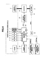
- any of the first, second and third power trains shown in FIGS. 1-3 may be controlled by a control system as shown in FIG. 4 .
- the control system is applicable to all of these power trains, as well as other power trains not shown, the following explanation is made with particular regard to the third power train shown in FIG. 3 wherein one of the friction elements of automatic transmission 3 is used as second clutch 7.
- the control system of FIG. 4 has an integrated controller 20 to control the operation points of the power train.
- the power train operation points are herein defined by a target torque tTe of engine 1, a target torque tTm of motor/generator 5, a target transmission torque capacity tTc1 of first clutch 6 and a target transmission torque capacity tTc2 of second clutch 7.
- Integrated controller 20 is, for example, a microcomputer including a random access memory (RAM), a read-only memory (ROM) and a central processing unit (CPU) in addition to various input and output connections.
- RAM random access memory
- ROM read-only memory
- CPU central processing unit
- the control functions described herein are performed by execution by the CPU of one or more software programs stored in ROM.
- some or all of the functions of integrated controller 20 can be implemented by hardware components.
- integrated controller 20 receives a signal from an engine rotation sensor 11 for detecting a rotational speed Ne of engine 1, a signal from motor/generator rotation sensor 12 for detecting a rotational speed Nm of motor/generator 5, a signal from a transmission input rotation sensor 13 for detecting a rotational speed Ni of transmission input shaft 3a, a signal from a transmission output rotation sensor 14 for detecting a rotational speed No of transmission output shaft 3b, a signal from an accelerator opening sensor 15 for detecting an accelerator pedal depression amount (accelerator opening APO) corresponding to a requested load of engine 1, a signal from a storage state sensor 16 for detecting a stage of charge SOC of a battery 9 (or an amount of electrical power that can be taken out of battery 9), a signal from a transmission oil temperature sensor 17 for detecting an operating oil temperature TEMPat of automatic transmission 3 corresponding to a temperature of second clutch 7 and a signal from an electric drive control coolant temperature sensor 18 for detecting a coolant temperature
- integrated controller 20 Based on the accelerator opening APO, the battery charge state SOC and the transmission output rotational speed No (vehicle speed VSP), integrated controller 20 carries out vehicle drive control operation by selecting either the EV mode or the HEV mode to achieve a vehicle driving force according to a driver's request and calculating the target engine torque tTe, the target motor/generator torque tTm, the target first clutch transmission torque capacity tTc1 and the target second clutch transmission torque capacity tTc2.
- the target engine torque tTe is output by integrated controller 20 to engine controller 21 so that engine controller 21 controls engine 1 to adjust the actual engine torque Te to the target engine torque tTe.
- the target motor/generator torque tTm is output from integrated controller 20 to motor/generator controller 22 so that motor/generator controller 22 controls motor/generator 5 using battery 9 and inverter 10 to adjust the actual motor/generator torque Tm to the target motor/generator torque tTm.
- Integrated controller 20 further supplies solenoid control currents to first and second clutches 6 and 7 in order to adjust the actual torque transmission capacities Tc1 and Tc2 to the target torque transmission capacities tTc1 and tTc2, respectively, for individual clutch engagement control.
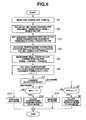
- Integrated controller 20 is configured to control mode changeover (mode selection) between the EV mode and the HEV mode by executing a control program such as that shown in the flowchart of FIG. 5 .
- step S1 integrated controller 20 reads vehicle speed VSP, transmission oil temperature TEMPat and electric drive control coolant temperature TEMPmg.
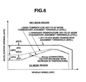
- step S2 integrated controller 20 sets an EV-to-HEV mode changeover judgment accelerator opening threshold level ⁇ based on an EV-to-HEV mode changeover judgment accelerator opening threshold line as indicated by a solid line in FIG. 6 .
- the EV-to-HEV mode changeover judgment threshold line (level ⁇ ) is used to judge whether to allow a changeover from the EV mode to the HEV mode when the accelerator opening APO becomes greater than or equal to the judgment threshold level ⁇ at a respective vehicle speed VSP.
- the EV-to-HEV mode changeover judgment threshold level ⁇ is set constant irrespective of the vehicle speed VSP within a given vehicle speed range.
- the EV-to-HEV mode changeover judgment threshold level ⁇ corresponds to an upper limit of the accelerator opening APO, with respect to each vehicle speed VSP, at which motor/generator 5 can be operated for EV driving so as to preserve a sufficient motor torque for engine start at the time of changeover from the EV mode to the HEV mode, and can be predetermined, for example, by experimentation. If the accelerator opening APO is greater than the EV-to-HEV mode changeover judgment threshold line (level ⁇ ) during the EV mode, motor/generator 5 uses a large torque to rotate driving wheels 2 and cannot produce a sufficient torque to start engine 1 at the changeover from the EV mode to the HEV mode. This results in a failure of the changeover from the EV mode to the HEV mode.
- step S3 integrated controller 20 sets an ordinary-temperature HEV-to-EV mode changeover judgment accelerator opening threshold level ⁇ based on an ordinary-temperature HEV-to-EV mode changeover judgment accelerator opening threshold line as indicated by a broken line in FIG. 6 .
- the ordinary-temperature HEV-to-EV mode changeover judgment threshold line (level ⁇ ) is used to judge whether to allow a changeover from the HEV mode to the EV mode with engine stop when the accelerator opening APO becomes smaller than the judgment threshold level ⁇ with respect to each vehicle speed VSP under ordinary temperature conditions after warm-up.
- the ordinary-temperature HEV-to-EV mode changeover judgment threshold level ⁇ is set lower than the HEV-to-EV mode changeover judgment threshold level ⁇ , so that there is hysteresis ⁇ APO between these judgment threshold levels ⁇ and ⁇ .
- the ordinary-temperature HEV-to-EV mode changeover judgment threshold line (level ⁇ ) is lowered with respect to the HEV-to-EV mode changeover judgment threshold line (level ⁇ ) in such a manner that the amount (width) of hysteresis ⁇ APO increases as the vehicle speed decreases, as explained hereinafter.
- the ordinary-temperature HEV-to-EV mode changeover judgment threshold level ⁇ decreases at a constant gradient with respect to the vehicle speed in FIG. 6 , but may alternatively decrease in a non-constant manner, for example, in steps.
- integrated controller 20 retrieves an oil temperature correction factor Ktempat (0 ⁇ Ktempat ⁇ 1), relative to the ordinary-temperature HEV-to-EV mode changeover judgment threshold line (level ⁇ ), based on the vehicle speed VSP and the transmission oil temperature TEMPat (i.e., the temperature of second clutch 7). Also at step S4, integrated controller 20 retrieves a coolant temperature correction factor Ktempmg (0 ⁇ Ktempmg ⁇ 1), relative to the ordinary-temperature HEV-to-EV mode changeover judgment threshold line (level ⁇ ), based on the vehicle speed VSP and electric drive control coolant temperature TEMPmg (i.e., the temperature of electric drive control system including motor/generator 5 and inverter 10). Both of the oil temperature correction factor Ktempat and the coolant temperature correction factor Ktempmg decrease with increase in temperature and decrease with vehicle speed.
- both the oil temperature correction factor Ktempat (0 ⁇ Ktempat ⁇ 1) and the coolant temperature correction factor Ktempmg (0 ⁇ Ktempmg ⁇ 1) decrease with increases in temperature and decrease with vehicle speed.
- the final temperature correction factor Ktemp (0 ⁇ Ktemp ⁇ 1) which is obtained by multiplying Ktempat by Ktempmg, also decreases with increases in temperature and decreases with vehicle speed.
- the amount of hysteresis ⁇ APO between the EV-to-HEV mode changeover judgment threshold line (level ⁇ ) and the high-temperature HEV-to-EV mode changeover judgment threshold line (level ⁇ ) is made larger than that between the EV-to-HEV mode changeover judgment threshold line (level ⁇ ) and the ordinary-temperature HEV-to-EV mode changeover judgment threshold line (level ⁇ ).
- This hysteresis ⁇ APO increases with the transmission oil temperature TEMPat (the temperature of second clutch 7) and the electric drive control coolant temperature TEMPmg (the temperature of the electric drive control system including motor/generator 5 and inverter 10) and increases with decrease in the vehicle speed VSP.
- the high-temperature HEV-to-EV mode changeover judgment threshold line (level ⁇ ) coincides with the ordinary-temperature HEV-to-EV mode changeover judgment threshold line (level ⁇ ) when the correction factor Ktemp is set to 1 at ordinary temperature.
- step S7 integrated controller 20 judges whether the current selection mode is in either the EV mode or the HEV mode.
- step S7 If it is judged at step S7 that the EV mode is selected, integrated controller 20 checks at step S8 whether the accelerator opening APO is greater than or equal to the EV-to-HEV mode changeover judgment threshold level ⁇ .
- integrated controller 20 allows a changeover from the EV mode to the HEV mode at step S9. If APO ⁇ ⁇ , integrated controller 20 maintains the currently selected EV mode at step S10.
- integrated controller 20 checks at step S11 whether the accelerator opening APO is smaller than the high-temperature HEV-to-EV mode changeover judgment threshold level ⁇ (which coincides with the ordinary-temperature HEV-to-EV mode changeover judgment threshold level ⁇ at ordinary temperature).
- integrated controller 20 allows a changeover from the HEV mode to the EV mode at step S12. If APO ⁇ ⁇ , integrated controller 20 maintains the currently selected HEV mode at step S13.
- VSP vehicle speed
- TEMPat and TEMPmg driving environment
- This prevents frequent changeovers from the EV mode to the HEV mode accompanied by starting of the engine and from the HEV mode to the EV mode accompanied by stopping of the engine in response to large accelerator opening changes.
- it is possible to reduce deteriorations in vehicle fuel efficiency and driving performance that would be caused by frequent mode changeovers.
- VSP high vehicle speed
- SOC dischargeable battery power
- the accelerator opening hysteresis ⁇ APO is changed depending on not only the vehicle speed conditions (vehicle operating state) but also the vehicle driving environment (temperatures TEMPat and TEMPmg) so that the hysteresis ⁇ APO increases as the transmission oil temperature TEMPat (the temperature of second clutch 7) becomes higher than the ordinary temperature and increases as the electric drive control coolant temperature TEMPmg (the temperature of electric drive control system including motor/generator 5 and inverter 10) becomes higher than the ordinary temperature.
- ⁇ APO ⁇ - ⁇
- VSP vehicle speed
- TEMPat and TEMPmg driving environment
- the EV-to-HEV mode changeover judgment threshold level ⁇ generally corresponds to the upper limit of the accelerator opening APO at which motor/generator 5 can be operated for EV driving so as to preserve a sufficient motor torque for engine start at the time of changeover from the EV mode to the HEV mode. If the accelerator opening APO is greater than the EV-to-HEV mode changeover judgment threshold level ⁇ under the EV mode, motor/generator 5 uses a large torque to rotate driving wheels 2 and cannot produce a sufficient torque to start engine 1 at the changeover from the EV mode to the HEV mode. This results in a failure of the changeover from the EV mode to the HEV mode.
Abstract
Description
- The invention relates to the field of hybrid vehicles and particularly, but not exclusively, to a mode changeover control device for a hybrid vehicle. Aspects of the invention relate to a device, to an apparatus, to a method and to a vehicle.
- Typical hybrid vehicles are equipped with an engine and a electric motor as propulsion sources so as to allow a changeover between an electric drive mode (EV mode, motor drive mode) in which the vehicle is propelled only by the electric motor and a hybrid drive mode (HEV mode, combination drive mode) in which the vehicle is propelled by both the engine and the electric motor. In order to switch between the electric drive mode and the hybrid drive mode, various hybrid vehicle mode changeover control devices have been proposed.
- For example,
Japanese Laid-Open Patent Publication No. 6-48190 - It is an aim of the present invention to improve upon such known technology. Other aims and advantages of the invention will become apparent from the following description, claims and drawings.
- Aspects of the invention therefore provide an apparatus, a method and a vehicle as claimed in the appended claims.
- According to another aspect of the invention for which protection is sought there is provided a control device for a hybrid vehicle including an engine, a motor/generator, and at least one driving wheel, the hybrid vehicle operable in an electric drive mode in which the vehicle is powered only by the motor/generator and a hybrid drive mode in which the vehicle is powered by both the engine and the motor/generator, the control device comprising a controller configured to set a first threshold level of an accelerator opening, set a second threshold level of the accelerator opening, wherein a hysteresis value is defined between the first threshold level and the second threshold level, change the hysteresis value based on at least one of a vehicle operating state and a driving environment, receive a signal corresponding to the accelerator opening, initiate a changeover from the hybrid drive mode to the electric drive mode if the accelerator opening is less than the first threshold level and initiate a changeover from the electric drive mode to the hybrid drive mode if the accelerator opening is greater than the second threshold value.
- In an embodiment, the at least one of the vehicle operating state and the driving environment includes a vehicle speed; and wherein the controller is further configured to change the hysteresis value by increasing the hysteresis value as the vehicle speed decreases.
- In an embodiment, the controller is further configured to change the hysteresis value by adjusting the first threshold level based on the at least one of the vehicle operating state and the driving environment.
- In an embodiment, the second threshold level remains unchanged in response to a change in the hysteresis value.
- In an embodiment, the controller is further configured to change the hysteresis value by decreasing the first threshold level with vehicle speed and maintaining the second threshold level at a constant value regardless of the vehicle speed.
- In an embodiment, the hybrid vehicle further comprises a first clutch disposed between the engine and the motor/generator to change a torque transmission capacity between the engine and the motor/generator and a second clutch disposed between the motor/generator and the at least one driving wheel to change a torque transmission capacity between the motor/generator and the at least one driving wheel; and wherein the control system further comprises the controller configured to initiate the changeover to the electric drive mode by signaling disengagement the first clutch and engagement of the second clutch and to initiate the changeover to the hybrid drive mode by signaling engagement of the first clutch and the second clutch and wherein the controller configured to change the hysteresis value by increasing the hysteresis value as the temperature of the second clutch increases.
- In an embodiment, the controller is configured to change the hysteresis value by increasing the hysteresis value as the temperature of an electric drive control system including the motor/generator increases.
- According to a further aspect of the invention for which protection is sought there is provided a control device of a hybrid vehicle including an engine, a motor/generator, and at least one driving wheel, the hybrid vehicle operable in an electric drive mode in which the vehicle is powered only by the motor/generator and a hybrid drive mode in which the vehicle is powered by both the engine and the motor/generator, the control system comprising means for setting a first threshold level of an accelerator opening, means for setting a second threshold level of the accelerator opening, wherein a hysteresis value is defined between the first threshold level and the second threshold level, means for changing the hysteresis value based on at least one of a vehicle operating state and a driving environment, means for receiving a signal corresponding to the accelerator opening, means for initiating a changeover from the hybrid drive mode to the electric drive mode if the accelerator opening is less than the first threshold level and means for initiating a changeover from the electric drive mode to the hybrid drive mode if the accelerator opening is greater than the second threshold value.
- According to a still further aspect of the invention for which protection is sought there is provided a method for controlling a hybrid vehicle including an engine, a motor/generator, and at least one driving wheel, the hybrid vehicle operable in an electric drive mode in which the vehicle is powered only by the motor/generator and a hybrid drive mode in which the vehicle is powered by both the engine and the motor/generator, the method comprising setting a first threshold level of an accelerator opening, setting a second threshold level of the accelerator opening, wherein a hysteresis value is defined between the first threshold level and the second threshold level, changing the hysteresis value based on at least one of a vehicle operating state and a driving environment, receiving a signal corresponding to the accelerator opening, initiating a changeover from the hybrid drive mode to the electric drive mode if the accelerator opening is less than the first threshold level and initiating a changeover from the electric drive mode to the hybrid drive mode if the accelerator opening is greater than the second threshold value.
- In an embodiment, the at least one of the vehicle operating state and the driving environment includes a vehicle speed; and wherein changing the hysteresis value further comprises increasing the hysteresis value as the vehicle speed decreases.
- In an embodiment, changing the hysteresis value further comprises adjusting the first threshold level based on the at least one of the vehicle operating state and the driving environment.
- In an embodiment, changing the hysteresis value further comprises increasing the hysteresis value as the temperature of an electric drive control system including the motor/generator increases.
- In an embodiment, changing the hysteresis value further comprises decreasing the first threshold level with vehicle speed based on a total amount of a change to the hysteresis value and maintaining the second threshold level unchanged in response to the change to the hysteresis value.
- In an embodiment, the hybrid vehicle further comprises a first clutch disposed between the engine and the motor/generator to change a torque transmission capacity between the engine and the motor/generator and a second clutch disposed between the motor/generator and the at least one driving wheel to change a torque transmission capacity between the motor/generator and the at least one driving wheel, the method further comprising initiating the changeover to the electric drive mode by signaling disengagement the first clutch and engagement of the second clutch and initiating the changeover to the hybrid drive mode by signaling engagement of the first clutch and the second clutch; and wherein changing the hysteresis value by increasing the hysteresis value as the temperature of the second clutch increases.
- Control devices and methods for a hybrid vehicle including an engine, a motor/generator and at least one driving wheel are taught herein. The hybrid vehicle may be operable in an electric drive mode in which the vehicle is powered only by the motor/generator and a hybrid drive mode in which the vehicle is powered by both the engine and the motor/generator. One example of a control system taught herein comprises a controller configured to set a first threshold level of an accelerator opening, set a second threshold level of the accelerator opening, wherein a hysteresis value is defined between the first threshold level and the second threshold level, change the hysteresis value based on at least one of a vehicle operating state and a driving environment, receive a signal corresponding to the accelerator opening, initiate a changeover from the hybrid drive mode to the electric drive mode if the accelerator opening is less than the first threshold level and initiate a changeover from the electric drive mode to the hybrid drive mode if the accelerator opening is greater than the second threshold value.
- Within the scope of this application it is envisaged that the various aspects, embodiments, examples, features and alternatives set out in the preceding paragraphs, in the claims and/or in the following description and drawings may be taken individually or in any combination thereof.
- The present invention will now be described, by way of example only, with reference to the accompanying drawings in which:
-
FIG. 1 is a block diagram showing the power train of a first hybrid vehicle in which embodiments of the invention can be incorporated; -
FIG. 2 is a block diagram showing the power train of a second hybrid vehicle in which embodiments of the invention can be incorporated; -
FIG. 3 is a block diagram showing the power train of a third hybrid vehicle in which embodiments of the invention can be incorporated; -
FIG. 4 is a block diagram showing a control system according to an embodiment of the invention; -
FIG. 5 is a flow chart showing a mode changeover control program according to an embodiment of the invention; and -
FIG. 6 is a diagram showing a control characteristic with an EV mode region and a HEV mode region for the mode changeover control program according toFIG. 5 . -
FIG. 1 is a first power train for use in a front-engine, rear-wheel-drive hybrid vehicle with a hybrid drive system in which a mode changeover control device according to embodiments of the invention can be incorporated. This power train includes an engine 1, anautomatic transmission 3 arranged in tandem on the vehicle rear side of engine 1 and connected to a pair of driving wheels, namely left and rightrear wheels 2 of the vehicle, as in the case of an ordinary rear-wheel drive vehicle, ashaft 4 disposed between engine 1 andautomatic transmission 3 to transmit the torque of engine 1 (crankshaft 1a) to aninput shaft 3a ofautomatic transmission 3 andelectric motor 5 connected toshaft 4. Herein,electric motor 5 functions both as a motor and a generator as is referred to as motor/generator 5. - The power train shown in
FIG. 1 also includes afirst clutch 6 disposed between engine 1 and motor/generator 5, and more specifically betweenengine crankshaft 1 a andshaft 4, to selectively engage and disengage engine 1 and motor/generator 5.First clutch 6 is designed to change a transmission torque capacity and, for example, can be a wet-type multiple disc clutch capable of changing the transmission torque capacity by controlling its hydraulic operating oil flow amount and pressure continuously using a proportional solenoid. - The power train further includes a
second clutch 7 disposed between motor/generator 5, and more specifically betweenshaft 4 andtransmission input shaft 3a, to establish connection or disconnection between motor/generator 5 andautomatic transmission 3.Second clutch 7 is also designed to change a transmission torque capacity and, for example, can be a wet-type multiple disc clutch capable of changing the transmission torque capacity by controlling its hydraulic operating oil flow amount and pressure continuously using a proportional solenoid. -
Automatic transmission 3 has a plurality of friction elements, such as clutches and brakes, to define a transmission path (i.e., select a gear stage) by selective engagement and disengagement of these friction elements. In particular,automatic transmission 3 changes the torque ofinput shaft 3a at a gear ratio in accordance with the selected gear stage and outputs the resulting torque tooutput shaft 3b so that the output torque is distributed to left and rightrear wheels 2 by adifferential gear unit 8 for vehicle driving. It should be understood, however, thatautomatic transmission 3 is not limited to the above-mentioned multi-speed transmission. For example,automatic transmission 3 may be a continuously variable transmission. - In response to the demand for an electric drive (EV) mode at low-load, low-speed vehicle driving, e.g., where the vehicle starts from a standstill, the power train disengages
first clutch 6, engagessecond clutch 7 and placesautomatic transmission 3 into a power transmission state. When motor/generator 5 is driven in this state, only the output torque of motor/generator 5 is input totransmission input shaft 3a.Automatic transmission 3 changes the torque ofinput shaft 3a at a gear ratio in accordance with the selected gear stage and outputs the resulting torque totransmission output shaft 3b. The torque oftransmission output shaft 3b is transmitted torear wheels 2 throughdifferential gear unit 8. The vehicle is thus powered only by motor/generator 5 during electric driving (EV driving). - On the other hand, in response to the demand for a hybrid drive, or HEV mode, during high-load, high-speed vehicle driving, the power train engages both
first clutch 6 andsecond clutch 7 and placesautomatic transmission 3 into the power transmission state. The rotation of engine 1 increases with the torque of motor/generator 5 by engagement offirst clutch 6 so that engine makes a start for changeover from the EV mode to the HEV mode. In this state, both the output torque of engine 1 and the output torque of motor/generator 5 are input toinput shaft 3a ofautomatic transmission 3.Automatic transmission 3 changes the torque ofinput shaft 3a at a gear ratio in accordance with the selected gear stage and outputs the resulting torque tooutput shaft 3b ofautomatic transmission 3. The torque ofoutput shaft 3b ofautomatic transmission 3 is transmitted torear wheels 2 throughdifferential gear unit 8. The vehicle is thus powered by both engine 1 and motor/generator 5 when the vehicle is operated in HEV mode. - When the vehicle is operated in HEV mode, there may be excess energy when engine 1 is operated at optimum fuel consumption. In such a case, motor/
generator 5 performs its generator function to convert the excess energy into electrical power, which is stored for subsequent use by the motor/generator 5 to improve the fuel consumption of engine 1. - Although
second clutch 7 is disposed between motor/generator 5 andautomatic transmission 3 to selectively engage and disengage motor/generator 5 andvehicle driving wheels 2 as shown in the first power train inFIG. 1 , in a second power train, thesecond clutch 7 may alternatively be disposed betweenautomatic transmission 3 anddifferential gear unit 8 as shown inFIG. 2 . - Further, although the dedicated
second clutch 7 is disposed on the front or rear side ofautomatic transmission 3 in the first and second power trains ofFIGS. 1 and 2 , respectively, in a third power train one of the friction elements ofautomatic transmission 3 may be used assecond clutch 7 as shown inFIG. 3 . In this case,second clutch 7 is engaged to perform its mode changeover function and to placeautomatic transmission 3 in the power transmission state. It is thus possible to eliminatesecond clutch 7 and thereby reduce the cost of the power train. - Any of the first, second and third power trains shown in
FIGS. 1-3 , may be controlled by a control system as shown inFIG. 4 . Although the control system is applicable to all of these power trains, as well as other power trains not shown, the following explanation is made with particular regard to the third power train shown inFIG. 3 wherein one of the friction elements ofautomatic transmission 3 is used assecond clutch 7. - The control system of
FIG. 4 has an integratedcontroller 20 to control the operation points of the power train. The power train operation points are herein defined by a target torque tTe of engine 1, a target torque tTm of motor/generator 5, a target transmission torque capacity tTc1 offirst clutch 6 and a target transmission torque capacity tTc2 ofsecond clutch 7.Integrated controller 20 is, for example, a microcomputer including a random access memory (RAM), a read-only memory (ROM) and a central processing unit (CPU) in addition to various input and output connections. Generally, the control functions described herein are performed by execution by the CPU of one or more software programs stored in ROM. Of course, some or all of the functions ofintegrated controller 20 can be implemented by hardware components. - In order to determine the power train operation points,
integrated controller 20 receives a signal from anengine rotation sensor 11 for detecting a rotational speed Ne of engine 1, a signal from motor/generator rotation sensor 12 for detecting a rotational speed Nm of motor/generator 5, a signal from a transmissioninput rotation sensor 13 for detecting a rotational speed Ni oftransmission input shaft 3a, a signal from a transmissionoutput rotation sensor 14 for detecting a rotational speed No oftransmission output shaft 3b, a signal from anaccelerator opening sensor 15 for detecting an accelerator pedal depression amount (accelerator opening APO) corresponding to a requested load of engine 1, a signal from astorage state sensor 16 for detecting a stage of charge SOC of a battery 9 (or an amount of electrical power that can be taken out of battery 9), a signal from a transmissionoil temperature sensor 17 for detecting an operating oil temperature TEMPat ofautomatic transmission 3 corresponding to a temperature ofsecond clutch 7 and a signal from an electric drive controlcoolant temperature sensor 18 for detecting a coolant temperature TEMPmg of an electric drive control system, namely motor/generator 5 in combination with aninverter 10. Herein,engine rotation sensor 11, motor/generator rotation sensor 12, transmissioninput rotation sensor 13 and transmissionoutput rotation sensor 14 can be arranged as shown inFIGS. 1 to 3 . - Based on the accelerator opening APO, the battery charge state SOC and the transmission output rotational speed No (vehicle speed VSP), integrated
controller 20 carries out vehicle drive control operation by selecting either the EV mode or the HEV mode to achieve a vehicle driving force according to a driver's request and calculating the target engine torque tTe, the target motor/generator torque tTm, the target first clutch transmission torque capacity tTc1 and the target second clutch transmission torque capacity tTc2. In particular, the target engine torque tTe is output byintegrated controller 20 toengine controller 21 so thatengine controller 21 controls engine 1 to adjust the actual engine torque Te to the target engine torque tTe. The target motor/generator torque tTm is output fromintegrated controller 20 to motor/generator controller 22 so that motor/generator controller 22 controls motor/generator 5 usingbattery 9 andinverter 10 to adjust the actual motor/generator torque Tm to the target motor/generator torque tTm.Integrated controller 20 further supplies solenoid control currents to first andsecond clutches -
Integrated controller 20 is configured to control mode changeover (mode selection) between the EV mode and the HEV mode by executing a control program such as that shown in the flowchart ofFIG. 5 . - At step S1 integrated
controller 20 reads vehicle speed VSP, transmission oil temperature TEMPat and electric drive control coolant temperature TEMPmg. - At step S2 integrated
controller 20 sets an EV-to-HEV mode changeover judgment accelerator opening threshold level α based on an EV-to-HEV mode changeover judgment accelerator opening threshold line as indicated by a solid line inFIG. 6 . - The EV-to-HEV mode changeover judgment threshold line (level α) is used to judge whether to allow a changeover from the EV mode to the HEV mode when the accelerator opening APO becomes greater than or equal to the judgment threshold level α at a respective vehicle speed VSP. As shown in
FIG. 6 , the EV-to-HEV mode changeover judgment threshold level α is set constant irrespective of the vehicle speed VSP within a given vehicle speed range. Herein, the EV-to-HEV mode changeover judgment threshold level α corresponds to an upper limit of the accelerator opening APO, with respect to each vehicle speed VSP, at which motor/generator 5 can be operated for EV driving so as to preserve a sufficient motor torque for engine start at the time of changeover from the EV mode to the HEV mode, and can be predetermined, for example, by experimentation. If the accelerator opening APO is greater than the EV-to-HEV mode changeover judgment threshold line (level α) during the EV mode, motor/generator 5 uses a large torque to rotate drivingwheels 2 and cannot produce a sufficient torque to start engine 1 at the changeover from the EV mode to the HEV mode. This results in a failure of the changeover from the EV mode to the HEV mode. - At step S3 integrated
controller 20 sets an ordinary-temperature HEV-to-EV mode changeover judgment accelerator opening threshold level β based on an ordinary-temperature HEV-to-EV mode changeover judgment accelerator opening threshold line as indicated by a broken line inFIG. 6 . - The ordinary-temperature HEV-to-EV mode changeover judgment threshold line (level β) is used to judge whether to allow a changeover from the HEV mode to the EV mode with engine stop when the accelerator opening APO becomes smaller than the judgment threshold level β with respect to each vehicle speed VSP under ordinary temperature conditions after warm-up. The ordinary-temperature HEV-to-EV mode changeover judgment threshold level β is set lower than the HEV-to-EV mode changeover judgment threshold level α, so that there is hysteresis ΔAPO between these judgment threshold levels α and β. In this embodiment, the ordinary-temperature HEV-to-EV mode changeover judgment threshold line (level β) is lowered with respect to the HEV-to-EV mode changeover judgment threshold line (level α) in such a manner that the amount (width) of hysteresis ΔAPO increases as the vehicle speed decreases, as explained hereinafter. The ordinary-temperature HEV-to-EV mode changeover judgment threshold level β decreases at a constant gradient with respect to the vehicle speed in
FIG. 6 , but may alternatively decrease in a non-constant manner, for example, in steps. - At step S4 integrated
controller 20 retrieves an oil temperature correction factor Ktempat (0 < Ktempat ≤ 1), relative to the ordinary-temperature HEV-to-EV mode changeover judgment threshold line (level β), based on the vehicle speed VSP and the transmission oil temperature TEMPat (i.e., the temperature of second clutch 7). Also at step S4, integratedcontroller 20 retrieves a coolant temperature correction factor Ktempmg (0 < Ktempmg ≤ 1), relative to the ordinary-temperature HEV-to-EV mode changeover judgment threshold line (level β), based on the vehicle speed VSP and electric drive control coolant temperature TEMPmg (i.e., the temperature of electric drive control system including motor/generator 5 and inverter 10). Both of the oil temperature correction factor Ktempat and the coolant temperature correction factor Ktempmg decrease with increase in temperature and decrease with vehicle speed. - At step S5 integrated
controller 20 multiplies the oil temperature correction factor Ktempat by the coolant temperature correction factor Ktempmg to determine a final temperature correction factor Ktemp (wherein Ktemp = Ktempat × Ktempmg) relative to the ordinary-temperature HEV-to-EV mode changeover judgment threshold line (level β). - At step S6 integrated
controller 20 multiplies the ordinary-temperature HEV-to-EV mode changeover judgment threshold line (level β) by the final temperature correction factor Ktemp to set a high-temperature HEV-to-EV mode changeover judgment threshold level γ (wherein γ = β × Ktemp). - As mentioned above, both the oil temperature correction factor Ktempat (0 < Ktempat ≤ 1) and the coolant temperature correction factor Ktempmg (0 < Ktempmg ≤ 1) decrease with increases in temperature and decrease with vehicle speed. The final temperature correction factor Ktemp (0 < Ktemp ≤ 1), which is obtained by multiplying Ktempat by Ktempmg, also decreases with increases in temperature and decreases with vehicle speed. As a result, the high-temperature HEV-to-EV mode changeover judgment threshold level γ, which is given by correction of the ordinary-temperature HEV-to-EV mode changeover judgment level β with the correction factor Ktemp (that is, γ = β × Ktemp), shows such a characteristic as indicated by a chain line in
FIG. 6 at a certain combination of the transmission oil temperature TEMPat (the temperature of second clutch 7) and the electric drive control coolant temperature TEMPmg (the temperature of electric drive control system including motor/generator 5 and inverter 10). - From the foregoing, it is seen that the amount of hysteresis ΔAPO between the EV-to-HEV mode changeover judgment threshold line (level α) and the high-temperature HEV-to-EV mode changeover judgment threshold line (level γ) is made larger than that between the EV-to-HEV mode changeover judgment threshold line (level α) and the ordinary-temperature HEV-to-EV mode changeover judgment threshold line (level β). This hysteresis ΔAPO increases with the transmission oil temperature TEMPat (the temperature of second clutch 7) and the electric drive control coolant temperature TEMPmg (the temperature of the electric drive control system including motor/
generator 5 and inverter 10) and increases with decrease in the vehicle speed VSP. Needless to say, the high-temperature HEV-to-EV mode changeover judgment threshold line (level γ) coincides with the ordinary-temperature HEV-to-EV mode changeover judgment threshold line (level β) when the correction factor Ktemp is set to 1 at ordinary temperature. - At step S7 integrated
controller 20 judges whether the current selection mode is in either the EV mode or the HEV mode. - If it is judged at step S7 that the EV mode is selected, integrated
controller 20 checks at step S8 whether the accelerator opening APO is greater than or equal to the EV-to-HEV mode changeover judgment threshold level α. - If APO ≥ α, integrated
controller 20 allows a changeover from the EV mode to the HEV mode at step S9. If APO < α, integratedcontroller 20 maintains the currently selected EV mode at step S10. - If it is judged at step S7 that the HEV mode is selected, integrated
controller 20 checks at step S11 whether the accelerator opening APO is smaller than the high-temperature HEV-to-EV mode changeover judgment threshold level γ (which coincides with the ordinary-temperature HEV-to-EV mode changeover judgment threshold level β at ordinary temperature). - If APO < γ, integrated
controller 20 allows a changeover from the HEV mode to the EV mode at step S12. If APO ≥ γ, integratedcontroller 20 maintains the currently selected HEV mode at step S13. - As explained above, the mode changeover control device of this embodiment is configured to allow a changeover from the EV mode to the HEV mode when the EV-to-HEV mode changeover condition of APO ≥ α is satisfied and allows a changeover from the HEV mode to the EV mode when the HEV-to-EV mode changeover condition of APO < γ is satisfied, while changing the amount of accelerator opening hysteresis ΔAPO (wherein ΔAPO = α - γ) between the EV-to-HEV mode changeover condition and the HEV-to-EV mode changeover condition depending on the vehicle operating state (vehicle speed VSP) and driving environment (temperatures TEMPat and TEMPmg). The following effects can be obtained by such a configuration.
- Where there is a tendency that the accelerator opening APO changes by a large degree, such as is experienced during low-speed, city driving, the hysteresis ΔAPO (wherein ΔAPO = α - γ) is set to a large amount with respect to the low vehicle speed VSP as shown in
FIG. 6 . This prevents frequent changeovers from the EV mode to the HEV mode accompanied by starting of the engine and from the HEV mode to the EV mode accompanied by stopping of the engine in response to large accelerator opening changes. Thus, it is possible to reduce deteriorations in vehicle fuel efficiency and driving performance that would be caused by frequent mode changeovers. - During high-speed driving, where there is a tendency that the accelerator opening changes slightly, such as is experienced during suburban or highway driving, the hysteresis ΔAPO (wherein ΔAPO = α - γ) is set to a small amount with respect to the high vehicle speed VSP as shown in
FIG. 6 so as to readily allow mode changeovers in response to small accelerator opening changes. This makes it possible to ensure changeover to the EV mode when the motor/generator torque and the battery charge state SOC (dischargeable battery power) are sufficient for EV driving. Thus, improved fuel efficiency and performance of the hybrid vehicle can be obtained. - The accelerator opening hysteresis ΔAPO is changed depending on not only the vehicle speed conditions (vehicle operating state) but also the vehicle driving environment (temperatures TEMPat and TEMPmg) so that the hysteresis ΔAPO increases as the transmission oil temperature TEMPat (the temperature of second clutch 7) becomes higher than the ordinary temperature and increases as the electric drive control coolant temperature TEMPmg (the temperature of electric drive control system including motor/
generator 5 and inverter 10) becomes higher than the ordinary temperature. This reduces the tendency to select the EV mode in which the electric drive control system including motor/generator 5 andinverter 10 is put under high load when the temperature of the electric drive control system is elevated, as well as reducing the frequency of changeovers between the HEV mode and the EV mode when the temperature ofsecond clutch 7 is elevated due to clutch slip control against engine start shock. The temperature increases of the electric drive system andsecond clutch 7 can be thus limited to prevent damage to the electric drive system and early deterioration ofsecond clutch 7 and its operating oil. - Further, the hysteresis ΔAPO (wherein ΔAPO = α - γ) is changed depending on the vehicle operating state (vehicle speed VSP) and driving environment (temperatures TEMPat and TEMPmg) as shown in
FIG. 6 by adjusting the HEV-to-EV mode changeover judgment threshold level β, γ while the EV-to-HEV mode changeover judgment level α remains constant. This produces the following effect. - The EV-to-HEV mode changeover judgment threshold level α generally corresponds to the upper limit of the accelerator opening APO at which motor/
generator 5 can be operated for EV driving so as to preserve a sufficient motor torque for engine start at the time of changeover from the EV mode to the HEV mode. If the accelerator opening APO is greater than the EV-to-HEV mode changeover judgment threshold level α under the EV mode, motor/generator 5 uses a large torque to rotate drivingwheels 2 and cannot produce a sufficient torque to start engine 1 at the changeover from the EV mode to the HEV mode. This results in a failure of the changeover from the EV mode to the HEV mode. Namely, motor/generator 5 cannot start engine 1 and cannot allow changeover from the EV mode to the HEV mode if the hysteresis ΔAPO (wherein ΔAPO = α - γ) is increased by shifting the EV-to-HEV mode changeover judgment threshold level α in a greater accelerator opening direction. - In this embodiment, however, the hysteresis ΔAPO (wherein ΔAPO = α - γ) is changed by adjusting the HEV-to-EV mode changeover judgment threshold level β, γ rather than the EV-to-HEV mode changeover judgment threshold level α. The above detriment can be thus avoided.
- The above-described embodiments have been described in order to allow easy understanding of the invention and do not limit the invention. On the contrary, the invention is intended to cover various modifications and equivalent arrangements included within the scope of the appended claims, which scope is to be accorded the broadest interpretation so as to encompass all such modifications and equivalent structure as is permitted under the law.
- This application claims priority from
Japanese Patent Application Nos. 2006-349851, filed 26th December 2006 2007-240878, filed 18th September 2007
Claims (10)
- A apparatus for controlling a hybrid vehicle having an engine, a motor/generator and at least one driving wheel and operable in an electric drive mode in which the vehicle is powered only by the motor/generator and a hybrid drive mode in which the vehicle is powered by both the engine and the motor/generator, the apparatus comprising control means for:setting a first threshold level of an accelerator opening;setting a second threshold level of the accelerator opening, wherein a hysteresis value is defined between the first threshold level and the second threshold level;changing the hysteresis value based on at least one of a vehicle operating state and a driving environment;receiving a signal corresponding to the accelerator opening;initiating a changeover from the hybrid drive mode to the electric drive mode if the accelerator opening is less than the first threshold level; andinitiating a changeover from the electric drive mode to the hybrid drive mode if the accelerator opening is greater than the second threshold value.
- An apparatus as claimed in claim 1, wherein:the at least one of the vehicle operating state and the driving environment includes a vehicle speed; andthe control means is arranged to change the hysteresis value by increasing the hysteresis value as the vehicle speed decreases.
- An apparatus as claimed in claim 1 or claim 2, wherein the control means is arranged to change the hysteresis value by adjusting the first threshold level based on the at least one of the vehicle operating state and the driving environment.
- An apparatus as claimed in any preceding claim, wherein the second threshold level remains unchanged in response to a change in the hysteresis value.
- An apparatus as claimed in any preceding claim, wherein the control means is arranged to change the hysteresis value by decreasing the first threshold level with vehicle speed and maintaining the second threshold level at a constant value regardless of the vehicle speed.
- An apparatus as claimed in claim 5, wherein the hybrid vehicle comprises a first clutch disposed between the engine and the motor/generator to change a torque transmission capacity between the engine and the motor/generator and a second clutch disposed between the motor/generator and the at least one driving wheel to change a torque transmission capacity between the motor/generator and the at least one driving wheel; and wherein the control means is arranged to:initiate the changeover to the electric drive mode by signaling disengagement the first clutch and engagement of the second clutch and to initiate the changeover to the hybrid drive mode by signaling engagement of the first clutch and the second clutch; andchange the hysteresis value by increasing the hysteresis value as the temperature of the second clutch increases.
- An apparatus as claimed in any preceding claim, wherein the control means is arranged to change the hysteresis value by increasing the hysteresis value as the temperature of an electric drive control system including the motor/generator increases.
- A method for controlling a hybrid vehicle comprising an engine, a motor/generator and at least one driving wheel and operable in an electric drive mode in which the vehicle is powered only by the motor/generator and a hybrid drive mode in which the vehicle is powered by both the engine and the motor/generator, the method comprising:setting a first threshold level of an accelerator opening;setting a second threshold level of the accelerator opening, wherein a hysteresis value is defined between the first threshold level and the second threshold level;changing the hysteresis value based on at least one of a vehicle operating state and a driving environment;receiving a signal corresponding to the accelerator opening;initiating a changeover from the hybrid drive mode to the electric drive mode if the accelerator opening is less than the first threshold level; andinitiating a changeover from the electric drive mode to the hybrid drive mode if the accelerator opening is greater than the second threshold value.
- A method as claimed in claim 8, wherein changing the hysteresis value comprises:decreasing the first threshold level with vehicle speed based on a total amount of a change to the hysteresis value; andmaintaining the second threshold level unchanged in response to the change to the hysteresis value.
- A vehicle having an apparatus or adapted to use a method as claimed in any preceding claim.
Applications Claiming Priority (2)
| Application Number | Priority Date | Filing Date | Title |
|---|---|---|---|
| JP2006349851 | 2006-12-26 | ||
| JP2007240878A JP5088058B2 (en) | 2006-12-26 | 2007-09-18 | Hybrid vehicle mode switching control device |
Publications (3)
| Publication Number | Publication Date |
|---|---|
| EP1939059A2 true EP1939059A2 (en) | 2008-07-02 |
| EP1939059A3 EP1939059A3 (en) | 2008-09-03 |
| EP1939059B1 EP1939059B1 (en) | 2010-07-14 |
Family
ID=39148751
Family Applications (1)
| Application Number | Title | Priority Date | Filing Date |
|---|---|---|---|
| EP07150202A Active EP1939059B1 (en) | 2006-12-26 | 2007-12-20 | Mode changeover control device for a hybrid vehicle |
Country Status (2)
| Country | Link |
|---|---|
| US (1) | US8060266B2 (en) |
| EP (1) | EP1939059B1 (en) |
Cited By (9)
| Publication number | Priority date | Publication date | Assignee | Title |
|---|---|---|---|---|
| EP2236374A1 (en) * | 2009-03-30 | 2010-10-06 | JATCO Ltd | Control apparatus for hybrid vehicle |
| WO2012130845A3 (en) * | 2011-03-29 | 2012-11-22 | Getrag Getriebe- Und Zahnradfabrik Hermann Hagenmeyer Gmbh & Cie Kg | Method for operating a hybrid drive train |
| WO2015036823A1 (en) * | 2013-09-12 | 2015-03-19 | Toyota Jidosha Kabushiki Kaisha | Control apparatus for hybrid vehicle |
| US9162664B2 (en) | 2010-05-05 | 2015-10-20 | Ford Global Technologies, Inc. | Vehicle and method for controlling an electric machine and/or engine therein |
| EP2792562A4 (en) * | 2011-12-15 | 2016-01-27 | Toyota Motor Co Ltd | Hybrid vehicle |
| EP2985171A1 (en) * | 2014-08-12 | 2016-02-17 | Hyundai Motor Company | Forced charging method for phev vehicles using motor and hsg |
| EP2631133A4 (en) * | 2010-10-21 | 2016-12-28 | Nissan Motor | Hybrid vehicle rapid deceleration control device |
| GB2553172A (en) * | 2017-04-13 | 2018-02-28 | Detroit Electric Ev Ltd | Electrical vehicle drive train and method of operation |
| US10024249B2 (en) | 2012-01-30 | 2018-07-17 | Jaguar Land Rover Limited | Motor vehicle controller and method of controlling a motor vehicle |
Families Citing this family (16)
| Publication number | Priority date | Publication date | Assignee | Title |
|---|---|---|---|---|
| US7846051B2 (en) * | 2007-05-11 | 2010-12-07 | Gm Global Technology Operations, Inc. | Hybrid powertrain with an engine input clutch and method of control |
| JP5680279B2 (en) * | 2008-03-06 | 2015-03-04 | 日産自動車株式会社 | Engine stop control device for hybrid vehicle |
| US8346421B2 (en) * | 2009-03-24 | 2013-01-01 | Ford Global Technologies, Llc | Method and system for initiating starting of an engine in a hybrid electric vehicle |
| US8087483B2 (en) * | 2009-05-26 | 2012-01-03 | GM Global Technology Operations LLC | Hybrid powertrain with torque-multiplying engine starting mechanism and method of controlling a hybrid powertrain |
| CN102114766B (en) * | 2009-12-31 | 2014-03-19 | 比亚迪股份有限公司 | Hybrid drive system and driving method thereof |
| JP5742124B2 (en) * | 2010-07-21 | 2015-07-01 | 日産自動車株式会社 | Control device for hybrid vehicle |
| CN103917425B (en) * | 2011-11-11 | 2016-09-14 | 丰田自动车株式会社 | Hybrid electric drive system |
| JP5962463B2 (en) * | 2012-11-27 | 2016-08-03 | 三菱自動車工業株式会社 | Engine start determination device |
| KR101405198B1 (en) * | 2012-12-07 | 2014-06-27 | 기아자동차 주식회사 | Method and system for controlling anti jerk of hybrid electric vehicle |
| US9031722B2 (en) * | 2012-12-10 | 2015-05-12 | Ford Global Technologies, Llc | Method and system for improving hybrid vehicle shifting |
| JP5967110B2 (en) * | 2013-01-08 | 2016-08-10 | トヨタ自動車株式会社 | Control device for hybrid vehicle |
| US10427543B2 (en) * | 2014-07-23 | 2019-10-01 | Nissan Motor Co., Ltd. | Motor control apparatus and motor control method |
| US10112597B2 (en) | 2016-08-23 | 2018-10-30 | Ford Global Technologies, Llc | Automatic drive mode selection |
| KR101813542B1 (en) * | 2016-10-06 | 2018-01-30 | 현대자동차주식회사 | A hybrid vehicle and controlling method for the same |
| CN111746259A (en) * | 2019-03-29 | 2020-10-09 | 乾碳国际公司 | Heavy truck oil-saving robot device and control method |
| JP7023906B2 (en) * | 2019-09-06 | 2022-02-22 | 本田技研工業株式会社 | Vehicle control device |
Citations (4)
| Publication number | Priority date | Publication date | Assignee | Title |
|---|---|---|---|---|
| JPH0648190A (en) | 1992-07-27 | 1994-02-22 | Aqueous Res:Kk | Hybrid type automobile |
| US5846155A (en) | 1995-07-19 | 1998-12-08 | Aisin Aw Co., Ltd. | Vehicular drive unit |
| US6428444B1 (en) | 1999-09-06 | 2002-08-06 | Toyota Jidosha Kabushiki Kaisha | Apparatus for controlling a vehicle and a method of controlling the vehicle |
| EP1375237A2 (en) | 1997-09-15 | 2004-01-02 | Honda Giken Kogyo Kabushiki Kaisha | Controlling apparatus for a hybrid car |
Family Cites Families (17)
| Publication number | Priority date | Publication date | Assignee | Title |
|---|---|---|---|---|
| DE2943554A1 (en) * | 1979-10-27 | 1981-05-07 | Volkswagenwerk Ag | HYBRID DRIVE FOR A VEHICLE, IN PARTICULAR MOTOR VEHICLE |
| US4405029A (en) * | 1980-01-02 | 1983-09-20 | Hunt Hugh S | Hybrid vehicles |
| US4470476A (en) * | 1981-11-16 | 1984-09-11 | Hunt Hugh S | Hybrid vehicles |
| KR0139981B1 (en) * | 1995-06-12 | 1998-07-15 | 김광호 | Hysteresis system having the uniform threshold voltage |
| JP3870505B2 (en) | 1997-08-29 | 2007-01-17 | アイシン・エィ・ダブリュ株式会社 | Hybrid drive device for vehicle |
| DE69824997T2 (en) * | 1997-09-15 | 2004-12-16 | Honda Giken Kogyo K.K. | Device for controlling a hybrid vehicle |
| JP3172490B2 (en) | 1998-05-18 | 2001-06-04 | 株式会社日立製作所 | Hybrid car |
| JP3369484B2 (en) * | 1998-09-02 | 2003-01-20 | 本田技研工業株式会社 | Control device for hybrid drive vehicle |
| US6554088B2 (en) * | 1998-09-14 | 2003-04-29 | Paice Corporation | Hybrid vehicles |
| DE10204982A1 (en) | 2002-02-06 | 2003-08-14 | Daimler Chrysler Ag | Hybrid drive for motor vehicles has an internal combustion engine linked to a gearbox via a clutch and first/second electric motors acting as drives/generators linked to the engine and gearbox |
| JP3906717B2 (en) * | 2002-03-19 | 2007-04-18 | トヨタ自動車株式会社 | Accelerator opening setting device and vehicle equipped with the same |
| DE10260435A1 (en) * | 2002-12-21 | 2004-07-01 | Volkswagen Ag | Controlling motor vehicle hybrid drive involves accelerating with electrical machine, starting engine, accelerating with electrical machine and engine with suitable operation of two clutches |
| DE102004006730A1 (en) | 2003-02-12 | 2004-08-26 | Luk Lamellen Und Kupplungsbau Beteiligungs Kg | Safety method for carrying out a clutch safety strategy for a motor vehicle's automatic gearbox during an activated crawl function reduces thermal load on the clutch through activation criteria |
| JP2004364453A (en) | 2003-06-06 | 2004-12-24 | Aisin Aw Co Ltd | Drive control device and method for motor vehicle, and its program |
| JP3701660B2 (en) * | 2003-07-04 | 2005-10-05 | 本田技研工業株式会社 | Control device for hybrid vehicle |
| DE102004002061A1 (en) | 2004-01-15 | 2005-08-04 | Zf Friedrichshafen Ag | Method for controlling and regulating a drive train of a hybrid vehicle and drive train of a hybrid vehicle |
| DE102004040315A1 (en) | 2004-08-20 | 2006-03-02 | Volkswagen Ag | Method for operating a hybrid motor-vehicle, involves division of drive torque into electric machine torque and combustion engine torque |
-
2007
- 2007-12-18 US US11/958,622 patent/US8060266B2/en active Active
- 2007-12-20 EP EP07150202A patent/EP1939059B1/en active Active
Patent Citations (4)
| Publication number | Priority date | Publication date | Assignee | Title |
|---|---|---|---|---|
| JPH0648190A (en) | 1992-07-27 | 1994-02-22 | Aqueous Res:Kk | Hybrid type automobile |
| US5846155A (en) | 1995-07-19 | 1998-12-08 | Aisin Aw Co., Ltd. | Vehicular drive unit |
| EP1375237A2 (en) | 1997-09-15 | 2004-01-02 | Honda Giken Kogyo Kabushiki Kaisha | Controlling apparatus for a hybrid car |
| US6428444B1 (en) | 1999-09-06 | 2002-08-06 | Toyota Jidosha Kabushiki Kaisha | Apparatus for controlling a vehicle and a method of controlling the vehicle |
Cited By (14)
| Publication number | Priority date | Publication date | Assignee | Title |
|---|---|---|---|---|
| EP2236374A1 (en) * | 2009-03-30 | 2010-10-06 | JATCO Ltd | Control apparatus for hybrid vehicle |
| US8512201B2 (en) | 2009-03-30 | 2013-08-20 | Jatco Ltd | Control apparatus for hybrid vehicle |
| US9162664B2 (en) | 2010-05-05 | 2015-10-20 | Ford Global Technologies, Inc. | Vehicle and method for controlling an electric machine and/or engine therein |
| EP2631133A4 (en) * | 2010-10-21 | 2016-12-28 | Nissan Motor | Hybrid vehicle rapid deceleration control device |
| WO2012130845A3 (en) * | 2011-03-29 | 2012-11-22 | Getrag Getriebe- Und Zahnradfabrik Hermann Hagenmeyer Gmbh & Cie Kg | Method for operating a hybrid drive train |
| US8831812B2 (en) | 2011-03-29 | 2014-09-09 | Getrag Getriebe- Und Zahnradfabrik Hermann Hagenmeyer Gmbh & Cie Kg | Method for operating a hybrid drivetrain |
| EP2792562A4 (en) * | 2011-12-15 | 2016-01-27 | Toyota Motor Co Ltd | Hybrid vehicle |
| US10024249B2 (en) | 2012-01-30 | 2018-07-17 | Jaguar Land Rover Limited | Motor vehicle controller and method of controlling a motor vehicle |
| WO2015036823A1 (en) * | 2013-09-12 | 2015-03-19 | Toyota Jidosha Kabushiki Kaisha | Control apparatus for hybrid vehicle |
| EP2985171A1 (en) * | 2014-08-12 | 2016-02-17 | Hyundai Motor Company | Forced charging method for phev vehicles using motor and hsg |
| CN105365809A (en) * | 2014-08-12 | 2016-03-02 | 现代自动车株式会社 | Forced charging method for phev vehicles using motor and hsg |
| US9428174B2 (en) | 2014-08-12 | 2016-08-30 | Hyundai Motor Company | Forced charging method for PHEV vehicles using motor and HSG |
| CN105365809B (en) * | 2014-08-12 | 2019-05-28 | 现代自动车株式会社 | Using motor and HSG to the forced charge method of PHEV vehicle |
| GB2553172A (en) * | 2017-04-13 | 2018-02-28 | Detroit Electric Ev Ltd | Electrical vehicle drive train and method of operation |
Also Published As
| Publication number | Publication date |
|---|---|
| US8060266B2 (en) | 2011-11-15 |
| EP1939059A3 (en) | 2008-09-03 |
| US20080154455A1 (en) | 2008-06-26 |
| EP1939059B1 (en) | 2010-07-14 |
Similar Documents
| Publication | Publication Date | Title |
|---|---|---|
| EP1939059B1 (en) | Mode changeover control device for a hybrid vehicle | |
| US7686112B2 (en) | Apparatus and method for controlling hybrid vehicle | |
| US8132635B2 (en) | Motor lock prevention control for hybrid electric vehicle | |
| CN101209711B (en) | Mode changeover control device for a hybrid vehicle | |
| EP1862364B1 (en) | Vehicle Control | |
| US9186975B2 (en) | Control apparatus for hybrid vehicle | |
| EP2631133B1 (en) | Hybrid vehicle rapid deceleration control device | |
| US8204659B2 (en) | Engine start control system for hybrid vehicle | |
| KR101423007B1 (en) | Apparatus and method for controlling hybrid vehicle | |
| JP5832736B2 (en) | Engine start control device for hybrid vehicle | |
| US8738209B2 (en) | Control device of vehicle drive apparatus | |
| JP5262197B2 (en) | Control device for hybrid vehicle | |
| EP2826655A2 (en) | Control device for a hybrid electric vehicle | |
| JP5125727B2 (en) | Hybrid vehicle start control device | |
| US9216734B2 (en) | Control device | |
| US8983703B2 (en) | Device for controlling hybrid vehicle | |
| JP5217396B2 (en) | Control device for hybrid vehicle | |
| JP2012116272A (en) | Regenerative control device for hybrid electric vehicle | |
| US9321456B2 (en) | Hybrid vehicle control device | |
| JP2008290492A (en) | Coast traveling control device for hybrid vehicle | |
| JP5287825B2 (en) | Idle control device for hybrid vehicle |
Legal Events
| Date | Code | Title | Description |
|---|---|---|---|
| PUAI | Public reference made under article 153(3) epc to a published international application that has entered the european phase |
Free format text: ORIGINAL CODE: 0009012 |
|
| AK | Designated contracting states |
Kind code of ref document: A2 Designated state(s): AT BE BG CH CY CZ DE DK EE ES FI FR GB GR HU IE IS IT LI LT LU LV MC MT NL PL PT RO SE SI SK TR |
|
| AX | Request for extension of the european patent |
Extension state: AL BA HR MK RS |
|
| PUAL | Search report despatched |
Free format text: ORIGINAL CODE: 0009013 |
|
| AK | Designated contracting states |
Kind code of ref document: A3 Designated state(s): AT BE BG CH CY CZ DE DK EE ES FI FR GB GR HU IE IS IT LI LT LU LV MC MT NL PL PT RO SE SI SK TR |
|
| AX | Request for extension of the european patent |
Extension state: AL BA HR MK RS |
|
| 17P | Request for examination filed |
Effective date: 20090303 |
|
| 17Q | First examination report despatched |
Effective date: 20090407 |
|
| AKX | Designation fees paid |
Designated state(s): DE FR GB |
|
| GRAP | Despatch of communication of intention to grant a patent |
Free format text: ORIGINAL CODE: EPIDOSNIGR1 |
|
| GRAS | Grant fee paid |
Free format text: ORIGINAL CODE: EPIDOSNIGR3 |
|
| GRAA | (expected) grant |
Free format text: ORIGINAL CODE: 0009210 |
|
| AK | Designated contracting states |
Kind code of ref document: B1 Designated state(s): DE FR GB |
|
| REG | Reference to a national code |
Ref country code: GB Ref legal event code: FG4D |
|
| REF | Corresponds to: |
Ref document number: 602007007719 Country of ref document: DE Date of ref document: 20100826 Kind code of ref document: P |
|
| PLBE | No opposition filed within time limit |
Free format text: ORIGINAL CODE: 0009261 |
|
| STAA | Information on the status of an ep patent application or granted ep patent |
Free format text: STATUS: NO OPPOSITION FILED WITHIN TIME LIMIT |
|
| 26N | No opposition filed |
Effective date: 20110415 |
|
| REG | Reference to a national code |
Ref country code: DE Ref legal event code: R097 Ref document number: 602007007719 Country of ref document: DE Effective date: 20110415 |
|
| REG | Reference to a national code |
Ref country code: FR Ref legal event code: PLFP Year of fee payment: 9 |
|
| REG | Reference to a national code |
Ref country code: FR Ref legal event code: PLFP Year of fee payment: 10 |
|
| REG | Reference to a national code |
Ref country code: FR Ref legal event code: PLFP Year of fee payment: 11 |
|
| PGFP | Annual fee paid to national office [announced via postgrant information from national office to epo] |
Ref country code: GB Payment date: 20231124 Year of fee payment: 17 |
|
| PGFP | Annual fee paid to national office [announced via postgrant information from national office to epo] |
Ref country code: FR Payment date: 20231122 Year of fee payment: 17 Ref country code: DE Payment date: 20231121 Year of fee payment: 17 |