EP1933461A1 - Compressible capacitance sensor for determining the presence of an object - Google Patents
Compressible capacitance sensor for determining the presence of an object Download PDFInfo
- Publication number
- EP1933461A1 EP1933461A1 EP08003107A EP08003107A EP1933461A1 EP 1933461 A1 EP1933461 A1 EP 1933461A1 EP 08003107 A EP08003107 A EP 08003107A EP 08003107 A EP08003107 A EP 08003107A EP 1933461 A1 EP1933461 A1 EP 1933461A1
- Authority
- EP
- European Patent Office
- Prior art keywords
- seat
- sensor
- seat occupant
- flexible conductor
- capacitance
- Prior art date
- Legal status (The legal status is an assumption and is not a legal conclusion. Google has not performed a legal analysis and makes no representation as to the accuracy of the status listed.)
- Withdrawn
Links
- 239000004020 conductor Substances 0.000 claims abstract description 80
- 238000000926 separation method Methods 0.000 claims abstract description 25
- 230000004044 response Effects 0.000 claims abstract description 19
- 230000001419 dependent effect Effects 0.000 claims abstract description 7
- 230000003247 decreasing effect Effects 0.000 claims abstract description 6
- 230000007423 decrease Effects 0.000 claims abstract description 5
- 238000000034 method Methods 0.000 description 11
- 230000008569 process Effects 0.000 description 10
- 230000008859 change Effects 0.000 description 4
- 239000006260 foam Substances 0.000 description 4
- 229920002943 EPDM rubber Polymers 0.000 description 2
- 230000003044 adaptive effect Effects 0.000 description 2
- 238000001514 detection method Methods 0.000 description 2
- 229920001971 elastomer Polymers 0.000 description 2
- 230000007613 environmental effect Effects 0.000 description 2
- 238000003475 lamination Methods 0.000 description 2
- 238000012544 monitoring process Methods 0.000 description 2
- 229920002799 BoPET Polymers 0.000 description 1
- RYGMFSIKBFXOCR-UHFFFAOYSA-N Copper Chemical compound [Cu] RYGMFSIKBFXOCR-UHFFFAOYSA-N 0.000 description 1
- 241001465754 Metazoa Species 0.000 description 1
- 239000005041 Mylar™ Substances 0.000 description 1
- 239000004820 Pressure-sensitive adhesive Substances 0.000 description 1
- 230000004913 activation Effects 0.000 description 1
- XAGFODPZIPBFFR-UHFFFAOYSA-N aluminium Chemical compound [Al] XAGFODPZIPBFFR-UHFFFAOYSA-N 0.000 description 1
- 229910052782 aluminium Inorganic materials 0.000 description 1
- 230000003321 amplification Effects 0.000 description 1
- 230000006835 compression Effects 0.000 description 1
- 238000007906 compression Methods 0.000 description 1
- 229910052802 copper Inorganic materials 0.000 description 1
- 239000010949 copper Substances 0.000 description 1
- 239000000806 elastomer Substances 0.000 description 1
- 238000001125 extrusion Methods 0.000 description 1
- 238000001914 filtration Methods 0.000 description 1
- 230000004927 fusion Effects 0.000 description 1
- 239000000463 material Substances 0.000 description 1
- 230000013011 mating Effects 0.000 description 1
- 239000011159 matrix material Substances 0.000 description 1
- 238000012986 modification Methods 0.000 description 1
- 230000004048 modification Effects 0.000 description 1
- 238000003199 nucleic acid amplification method Methods 0.000 description 1
- 238000007789 sealing Methods 0.000 description 1
- 125000000391 vinyl group Chemical group [H]C([*])=C([H])[H] 0.000 description 1
- 229920002554 vinyl polymer Polymers 0.000 description 1
Images

Classifications
-
- B—PERFORMING OPERATIONS; TRANSPORTING
- B60—VEHICLES IN GENERAL
- B60R—VEHICLES, VEHICLE FITTINGS, OR VEHICLE PARTS, NOT OTHERWISE PROVIDED FOR
- B60R21/00—Arrangements or fittings on vehicles for protecting or preventing injuries to occupants or pedestrians in case of accidents or other traffic risks
- B60R21/01—Electrical circuits for triggering passive safety arrangements, e.g. airbags, safety belt tighteners, in case of vehicle accidents or impending vehicle accidents
- B60R21/015—Electrical circuits for triggering passive safety arrangements, e.g. airbags, safety belt tighteners, in case of vehicle accidents or impending vehicle accidents including means for detecting the presence or position of passengers, passenger seats or child seats, and the related safety parameters therefor, e.g. speed or timing of airbag inflation in relation to occupant position or seat belt use
- B60R21/01512—Passenger detection systems
- B60R21/01516—Passenger detection systems using force or pressure sensing means
-
- B—PERFORMING OPERATIONS; TRANSPORTING
- B60—VEHICLES IN GENERAL
- B60N—SEATS SPECIALLY ADAPTED FOR VEHICLES; VEHICLE PASSENGER ACCOMMODATION NOT OTHERWISE PROVIDED FOR
- B60N2/00—Seats specially adapted for vehicles; Arrangement or mounting of seats in vehicles
- B60N2/002—Seats provided with an occupancy detection means mounted therein or thereon
-
- B—PERFORMING OPERATIONS; TRANSPORTING
- B60—VEHICLES IN GENERAL
- B60R—VEHICLES, VEHICLE FITTINGS, OR VEHICLE PARTS, NOT OTHERWISE PROVIDED FOR
- B60R21/00—Arrangements or fittings on vehicles for protecting or preventing injuries to occupants or pedestrians in case of accidents or other traffic risks
- B60R21/01—Electrical circuits for triggering passive safety arrangements, e.g. airbags, safety belt tighteners, in case of vehicle accidents or impending vehicle accidents
- B60R21/015—Electrical circuits for triggering passive safety arrangements, e.g. airbags, safety belt tighteners, in case of vehicle accidents or impending vehicle accidents including means for detecting the presence or position of passengers, passenger seats or child seats, and the related safety parameters therefor, e.g. speed or timing of airbag inflation in relation to occupant position or seat belt use
- B60R21/01512—Passenger detection systems
- B60R21/01516—Passenger detection systems using force or pressure sensing means
- B60R21/01526—Passenger detection systems using force or pressure sensing means using piezoelectric elements
-
- B—PERFORMING OPERATIONS; TRANSPORTING
- B60—VEHICLES IN GENERAL
- B60R—VEHICLES, VEHICLE FITTINGS, OR VEHICLE PARTS, NOT OTHERWISE PROVIDED FOR
- B60R21/00—Arrangements or fittings on vehicles for protecting or preventing injuries to occupants or pedestrians in case of accidents or other traffic risks
- B60R21/01—Electrical circuits for triggering passive safety arrangements, e.g. airbags, safety belt tighteners, in case of vehicle accidents or impending vehicle accidents
- B60R21/015—Electrical circuits for triggering passive safety arrangements, e.g. airbags, safety belt tighteners, in case of vehicle accidents or impending vehicle accidents including means for detecting the presence or position of passengers, passenger seats or child seats, and the related safety parameters therefor, e.g. speed or timing of airbag inflation in relation to occupant position or seat belt use
- B60R21/01512—Passenger detection systems
- B60R21/0153—Passenger detection systems using field detection presence sensors
- B60R21/01532—Passenger detection systems using field detection presence sensors using electric or capacitive field sensors
-
- G—PHYSICS
- G01—MEASURING; TESTING
- G01D—MEASURING NOT SPECIALLY ADAPTED FOR A SPECIFIC VARIABLE; ARRANGEMENTS FOR MEASURING TWO OR MORE VARIABLES NOT COVERED IN A SINGLE OTHER SUBCLASS; TARIFF METERING APPARATUS; MEASURING OR TESTING NOT OTHERWISE PROVIDED FOR
- G01D5/00—Mechanical means for transferring the output of a sensing member; Means for converting the output of a sensing member to another variable where the form or nature of the sensing member does not constrain the means for converting; Transducers not specially adapted for a specific variable
- G01D5/12—Mechanical means for transferring the output of a sensing member; Means for converting the output of a sensing member to another variable where the form or nature of the sensing member does not constrain the means for converting; Transducers not specially adapted for a specific variable using electric or magnetic means
- G01D5/14—Mechanical means for transferring the output of a sensing member; Means for converting the output of a sensing member to another variable where the form or nature of the sensing member does not constrain the means for converting; Transducers not specially adapted for a specific variable using electric or magnetic means influencing the magnitude of a current or voltage
- G01D5/24—Mechanical means for transferring the output of a sensing member; Means for converting the output of a sensing member to another variable where the form or nature of the sensing member does not constrain the means for converting; Transducers not specially adapted for a specific variable using electric or magnetic means influencing the magnitude of a current or voltage by varying capacitance
- G01D5/241—Mechanical means for transferring the output of a sensing member; Means for converting the output of a sensing member to another variable where the form or nature of the sensing member does not constrain the means for converting; Transducers not specially adapted for a specific variable using electric or magnetic means influencing the magnitude of a current or voltage by varying capacitance by relative movement of capacitor electrodes
- G01D5/2417—Mechanical means for transferring the output of a sensing member; Means for converting the output of a sensing member to another variable where the form or nature of the sensing member does not constrain the means for converting; Transducers not specially adapted for a specific variable using electric or magnetic means influencing the magnitude of a current or voltage by varying capacitance by relative movement of capacitor electrodes by varying separation
-
- E—FIXED CONSTRUCTIONS
- E05—LOCKS; KEYS; WINDOW OR DOOR FITTINGS; SAFES
- E05Y—INDEXING SCHEME RELATING TO HINGES OR OTHER SUSPENSION DEVICES FOR DOORS, WINDOWS OR WINGS AND DEVICES FOR MOVING WINGS INTO OPEN OR CLOSED POSITION, CHECKS FOR WINGS AND WING FITTINGS NOT OTHERWISE PROVIDED FOR, CONCERNED WITH THE FUNCTIONING OF THE WING
- E05Y2900/00—Application of doors, windows, wings or fittings thereof
- E05Y2900/50—Application of doors, windows, wings or fittings thereof for vehicles
- E05Y2900/53—Application of doors, windows, wings or fittings thereof for vehicles characterised by the type of wing
- E05Y2900/548—Trunk lids
-
- H—ELECTRICITY
- H03—ELECTRONIC CIRCUITRY
- H03K—PULSE TECHNIQUE
- H03K17/00—Electronic switching or gating, i.e. not by contact-making and –breaking
- H03K17/94—Electronic switching or gating, i.e. not by contact-making and –breaking characterised by the way in which the control signals are generated
- H03K17/96—Touch switches
- H03K17/962—Capacitive touch switches
Definitions
- the present invention is generally related to capacitance sensors for determining the presence of an object and, more particularly, to a capacitance sensor having a non-conductive compressible element between flexible conductors for determining the presence of an object.
- sensors are used to determine the presence, size, and/or position of an object such as a human body part.
- sensors are used for pinch sensing at electrically operated doors, windows, hatches, decks, hoods, lids, and the like and for seat occupant sensing.
- a pinch sensor detects the presence of an object such as a finger, hand, and the like being pinched by a closed opening such as a window.
- the pinch sensor generates a pinch signal in response to an object being pinched by the window.
- a controller controls the window to reverse direction to prevent further pinching and allow the object to be removed from the opening.
- a seat occupant sensor generates an occupant signal indicative of characteristics of an object such as a human occupant sitting on a seat.
- a controller uses the occupant signal to control various systems such as an air bag system as a function of the occupant's characteristics (adult or child) sitting on the seat.
- Motor current sensors, infrared beam sensors, and continuous switch sensors have been used for pinch sensing.
- a problem with motor current sensors and infrared beam sensors is that they can be fooled into causing an electrically closed opening to remain open due to changing mechanical and environmental conditions.
- a problem with continuous switch sensors is that they do not provide any lag time between switch activation and a pinch of an object. Thus, what is needed is a pinch sensor that is reliable in view of changing mechanical and environmental conditions and that provides a lag time to prevent a pinch of the object.
- Fiber-optic sensors, ultrasonic sensors, electromagnetic sensors, piezoimetric sensors, and switch matrix sensors have been used for seat occupant sensing.
- a problem with these types of seat occupant sensors is that they are complex and costly.
- a seat occupant sensor that is simple and cost efficient.
- the present invention provides a sensor for determining the presence of an object.
- the sensor includes first and second flexible conductor elements separated by a separation distance and having a capacitance dependent on the separation distance.
- a non-conductive compressible element is interposed between the first and second flexible conductor elements.
- the non-conductive compressible element compresses in response to an object applying a force to at least one of the first and second flexible conductor elements such that the separation distance between the first and second flexible conductor elements decreases.
- the capacitance of the first and second flexible conductor elements changes in response to the separation distance between the first and second flexible conductor elements decreasing.
- the sensor may include a controller for monitoring the capacitance of the first and second flexible conductor elements.
- the controller determines the presence of an object applying a force to at least one of the first and second flexible conductor elements in response to the capacitance of the first and second flexible conductor elements changing.
- the controller which may include a microprocessor, may be operable for generating an offset signal to bias the capacitance between the first and second flexible conductor elements.
- the controller may be operable for executing filtering software to monitor the capacitance between the first and second flexible conductor elements.
- the controller may be operable for executing an adaptive threshold detection algorithm to monitor the capacitance between the first and second flexible conductor elements.
- the first flexible conductor element may be a center core with the second flexible conductor element coaxially surrounding the non-conductive compressible element and the first flexible conductor element.
- the second flexible conductor element is preferably electrically grounded.
- An elastomeric overcoat may coaxially surround the second flexible conductor element.
- the sensor may further include a non-conductive compressible core.
- the first flexible conductor element coaxially surrounds the non conductive compressible core
- the non-conductive compressible element coaxially surrounds the first flexible conductor element
- the second flexible conductor element coaxially surrounds the non-conductive compressible element.
- the sensor may further include a third flexible conductor element.
- the second and third flexible conductor elements are electrically grounded and surround at least a portion of the first flexible conductor element.
- the non-conductive compressible element is interposed between the first, second, and third flexible conductor elements such that the first and second flexible conductor elements are separated by a first separation distance and have a first capacitance dependent on the first separation distance, and the first and third flexible conductor elements are separated by a second separation distance and have a second capacitance dependent on the second separation distance.
- the first and second capacitances change in response to the first and second separation distances decreasing when an object applies a force to at least one of the second and third flexible conductor elements.
- the non-conductive compressible element may include a cell foam, at least one of the first and second flexible conductors elements may include a braided electrically conductive wire or an electrically conductive plate.
- the present invention provides a pinch sensor system for determining the presence of an object within an opening defined by a closed opening device.
- the pinch sensor system includes a compressible capacitance pinch sensor fixedly positioned adjacent a closed opening device.
- the compressible capacitance pinch sensor has first and second flexible conductor elements separated by a separation distance.
- the first and second flexible conductor elements have a capacitance dependent on the separation distance.
- the compressible capacitance pinch sensor further has a non-conductive compressible element interposed between the first and second flexible conductor elements.
- the non-conductive compressible element compresses in response to an object within the opening touching the compressible capacitance pinch sensor such that the separation distance between the first and second flexible conductor elements decreases.
- the capacitance of the first and second flexible conductor elements changes in response to the separation distance between the first and second flexible conductor elements decreasing.
- the pinch sensor system further includes a controller for monitoring the capacitance of the first and second flexible conductor elements.
- the controller determines the presence of the object within the opening in response to the capacitance of the first and second flexible conductor elements changing.
- the controller controls the closed opening device as a function of the change in capacitance.
- the present invention provides a seat occupant sensor system.
- the seat occupant sensor system includes at least one seat occupant sensor disposed within a seat.
- the at least one seat occupant sensor includes first, second, and third flexible conductor plates.
- the first flexible conductor plate is interposed between the second and third flexible conductor plates such that the first and third flexible conductor plates are separated by a separation distance.
- the second and third flexible conductor plates are electrically grounded and the first, second, and third flexible conductor plates have a capacitance dependent on the separation distance.
- the at least one seat occupant sensor further includes a first non-conductive compressible element interposed between the first and second flexible conductor plates and a second non-conductive compressible element interposed between the first and third flexible conductor plates.
- the first and second non-conductive compressible elements compress in response to a seat occupant applying force to the at least one seat occupant sensor such that the separation distance between the second and third flexible conductor plates decreases.
- the capacitance changes in response to the separation distance decreasing.
- the seat occupant sensor system further includes a controller for determining characteristics of the seat occupant as a function of the capacitance of the at least one seat occupant sensor.
- the at least one seat occupant sensor may include a seat back sensor disposed within a seat back of the seat.
- the controller determines whether the seat occupant is sitting back on the seat back as a function of the capacitance of the seat back sensor.
- the at least one seat occupant sensor may include a seat bottom front sensor disposed within a front portion of a seat bottom of the seat.
- the controller determines whether the seat occupant is sitting short or forward on the seat bottom as a function of the capacitance of the seat bottom front sensor.
- the at least one seat occupant sensor may include a seat bottom left sensor disposed within a left portion of a seat bottom of the seat and a seat bottom right sensor disposed within a right portion of the seat bottom.
- the controller determines whether the seat occupant is sitting left or right on the seat bottom as a function of the capacitances of the seat bottom left and right sensors.
- the at least one seat occupant sensor may include at least one seat bottom sensor disposed within a seat bottom of the seat.
- the controller determines the weight of the seat occupant as a function of the capacitance of the at least one seat bottom sensor.
- the controller may be operable to reverse the polarity between the first, second, and third flexible conductor plates such that the first conductor plate is electrically grounded.
- the controller monitors the capacitance of the at least one seat occupant sensor after reversing the polarity to determine whether the seat occupant is an animate or inanimate object.
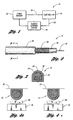
- Pinch sensor system 10 includes a capacitance pinch sensor 12 and a controller 14, Pinch sensor 12 monitors a closed opening device 16 such as an electrically operated window or door to determine whether an object such as a human body part is about to be pinched by the device or is being pinched by the device. In response to an object starting to be pinched by device 16 while the device is closing pinch sensor 12 generates a pinch sensor signal 18. Pinch sensor 12 then provides pinch sensor signal 18 to controller 14. In response to receiving pinch sensor signal 18, controller 14 transmits an open device control signal 20 to device 16. In response to receiving open device control signal 20, device 16 terminates closing and reverses its direction to open and allow the object to be removed from the closed opening thereby preventing any pinching of the object.
- a closed opening device 16 such as an electrically operated window or door
- Pinch sensor 12 monitors a closed opening device 16 such as an electrically operated window or door to determine whether an object such as a human body part is about to be pinched by the device or is being pinched by the device.
- a pinch sensor signal 18
- Pinch sensor 12 includes a flexible center conductive element or core 22 coaxially surrounded by a non-conductive compressible element or layer 26 that is in turn coaxially surrounded by a flexible outer conductive element or layer 24.
- Non-conductive compressible layer 26 separates conductive core 22 and conductive layer 24.
- Conductive layer 24 is electrically grounded and fully shields conductive core 22.
- An elastomeric overcoat 28 covers conductive layer 24.
- Conductive core 22 and conductive layer 24 are made from conductive materials such as aluminum, copper, and the like. Conductive core 22 and conductive layer 24 may each be a braided mesh which gives the conductive core and the conductive layer their flexibility.
- Non-conductive compressible layer 26 may be an EPDM closed cell foam having a high dielectric constant and a low compressible force. The dielectric constant and/or compressibility of non-conductive layer 26 may be changed by using different types of materials.
- Elastomeric overcoat 28 may be made from elastomer, rubber, vinyl, and the like. Elastomeric overcoat 28 may be flexible and/or compressible and may incorporate sealing elements.
- pinch sensor 12 is mounted to a fixed assembly such as an automobile window body panel 32.
- an object 30 such as a human body part is placed in an opening between pinch sensor 12 and closed opening device 16 such as an automobile window.
- the opening between pinch sensor 12 and window 16 is sufficiently large enough such that object 30 can move freely in the opening without being pinched by the window.
- window 16 starts to close in the direction of the arrow towards window body panel 32 and the opening becomes smaller such that object 30 is adjacent to pinch sensor 12 and window 16 and touches the pinch sensor.
- the pinch sensor compresses such that the distance between conductive core 22 and conductive layer 24 becomes smaller. As a result of this distance becoming smaller, the capacitance of pinch sensor 12 changes.
- Pinch sensor 12 then generates a pinch sensor signal 18 indicative of this change in capacitance to controller 14.
- Controller 14 processes pinch sensor signal 18 to determine that the capacitance of pinch sensor 12 has changed as a result of object 30 touching the pinch sensor and is about to be pinched by window 16.
- Controller 14 then transmits an open device control signal 20 to device 16 to reverse the direction of the device away from window body panel 32 thereby increasing the opening and allowing the object to be removed from the opening without any pinching of the object.
- controller 14 is an electronic controller such as a microprocessor based controller that includes a digital to analog (DAC) converter.
- the DAC converter allows for the subtraction (or an addition) of an offset voltage to allow for greater amplification of pinch sensor signal 18.
- Alternative embodiments could include analog waveform generation, such as a triangle wave, to accomplish the determination of the magnitude of the offset voltage for subsequent subtraction (or addition) thereof.
- the microprocessor of controller 14 may execute software for filtering and may use algorithms for adaptive threshold detection enabling determination of compression of pinch sensor 12.
- the microprocessor of controller 14 may be substituted with discrete electronic or a custom application specific integrated circuit that may include microprocessor core analog and digital circuitry.
- pinch sensor 34 in accordance with a second embodiment of the pinch sensor is shown.
- Pinch sensor 34 is similar to pinch sensor 12 but in place of conductive core 22, pinch sensor 34 includes a non-conductive compressible core 36 coaxially surrounded by a flexible conductor element or layer 38.
- Non-conductive compressible core and layer 36 and 26 may be made from the same closed cell foam.
- conductive layer 38 may also be a braided wire mesh made from a conductive material.
- pinch sensor 40 is similar to pinch sensor 12 but in place of the all encompassing conductive layer 24, pinch sensor 40 includes first and second flexible conductor shielding plates 42 and 44. Conductive core 22 is interposed between first and second conductor shielding plates 42 and 44. First and second conductor shielding plates 42 and 44 are electrically interconnected (not specifically shown).
- Pinch sensor 46 includes two flexible conductor core plates 48 and 50 and three flexible conductor shielding plates 52, 54, and 56. Conductor core plates 48 and 50 are alternatively disposed between conductor shielding plates 52, 54, and 56. Both pinch sensor 46 and pinch sensor 40 have the same width but pinch sensor 46 has a higher height than pinch sensor 40 as a result of the additional plates. As a result, pinch sensor 46 has a higher capacitance than pinch sensor 40.
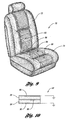
- Seat occupant sensor system 60 includes four seat capacitance sensors 62, 64, 66, and 68, and a controller 14.
- Seat sensors include a seat back sensor 62, a seat bottom left sensor 64, a seat bottom right sensor 66, and a seat bottom front sensor 68.
- Seat sensor 62, 64, 66, and 68 monitor a seat 70 to determine the characteristics such as presence, size, position, and type of an occupant of the seat.
- FIG. 9 illustrates the placement seat sensors 62, 64, 66, and 68 within seat 70.
- seat back sensor 62 is placed within a seat back 72 of seat 70.
- Seat bottom left and right sensors 64 and 66 are placed within the main sitting portion of a seat bottom 74 of seat 70.
- Seat bottom front sensor 68 is placed within the front sitting portion of seat bottom 74.
- Each seat sensor 62, 64, 66, and 68 monitors seat 70 and generates a respective seat sensor signal 76, 78, 80, and 82.
- Controller 14 receives seat sensor signals 76, 78, 80, and 82 and processes them to determine the characteristics of an occupant of seat 70.
- Controller 14 processes seat sensor signal 76 from seat back sensor 62 to determine if the occupant is sitting back on seat back 72.
- Controller 14 processes seat sensor signals 78, 80, and 82 from seat bottom left sensor 64, seat bottom right sensor 66, and seat bottom front sensor 68 to determine the weight of the occupant of seat 70.
- Controller 14 processes seat sensor signals 78 and 80 from seat bottom left and right sensors 64 and 66 to determine whether the seat occupant is sitting left or right in seat 70.
- Controller 14 processes seat sensor signal 82 from seat bottom front sensor 68 to determine whether the occupant of seat 70 is sitting short of forward in the seat. Controller 14 also processes seat sensor signal 76, 78, 80, and 82 to determine the size of the occupant of seat 70 as a short occupant puts relatively more weight on seat bottom front sensor 68. than a taller occupant.
- Controller 14 generates a seat control signal 84 as a function of the characteristics of the seat occupant as a result of processing seat sensor signals 62, 64, 66, and 68. Controller 14 then provides seat control signal 84 to seat 70 to control various systems associated with the seat. For instance, controller 14 may generate a seat control signal 84 causing an air bag system to deploy with a minimal force if the controller determines that the seat occupant is a child as a result of processing seat sensor signals 62, 64, 66, and 68.
- Seat occupant sensor 62 includes a flexible conductor center plate 86 and two flexible conductor shielding plates 88 and 90.
- a non-conductive compressible element or layer 92 separates conductor core plate 86 and shielding plate 88.
- a non-conductive compressible element or layer 94 separates conductor center plate 86 and shielding plate 90.
- Plates 88 and 90 are electrically interconnected by fusion or electrically conductive tape and are both electrically grounded.
- Non-conductive compressible layers 92 and 94 may be an EPDM closed cell foam like non-conductive compressible layer 26.
- Each of seat occupant sensors 62, 64, 66, and 68 is able to be configured into different shapes for placement into seat 70 as conductor plates 86, 88, and 90 are flexible and non-conductive layers 92 and 94 are compressible.
- Each of plates 86, 88, and 90 may be made from a lamination process although extrusion techniques may be used. For instance, plates 86, 88, and 90 may be super flex conductive wire weaved together or a mylar film with etched conductive devices.
- pressure sensitive adhesive is applied to the mating surfaces of non-conductive compressible layers 92 and 94.
- a release tape is applied to one edge of one of non-conductive compressible layers 92 or 94 to provide access to conductor core plate 86 for attachment of an electrical wire. The release tape is removed after the wire is attached to conductor core plate 86 and then the edge is bonded.
- Each of seat occupant sensors 62, 64, 66, and 68 operate like pinch sensor 12. That is, when a force is applied to a seat occupant sensor, the distance between shielding plates 88 and 90 with respect to center plate 86 changes as a function of the force applied to the seat occupant sensor. The capacitance of the seat occupant sensor likewise changes as a result of the distance between shielding plates 88 and 90 with respect to center plate 86 changing. Seat occupant sensor then provides a respective seat occupant sensor signal to controller 14 indicative of the change in capacitance as a result of the force applied to the seat occupant sensor. As described above, controller 14 processes the respective seat occupant sensor signals to determine the characteristics of the seat occupant such as weight, position, size, and the like.
- seat occupant system 60 may determine whether the occupant is a biological occupant such as a human or an animal occupant or an inanimate object. To do this, controller 14 reverses the polarity between center plate 86 and shielding plates 88 and 90 in order to monitor the capacitance characteristics of the occupant. A very high monitored capacitance of the occupant is indicative of a metallic object, a lower monitored capacitance is indicative of a biological occupant, and no monitored capacitance is indicative of an inanimate object.
Abstract

Description
- The present invention is generally related to capacitance sensors for determining the presence of an object and, more particularly, to a capacitance sensor having a non-conductive compressible element between flexible conductors for determining the presence of an object.
- Various types of sensors are used to determine the presence, size, and/or position of an object such as a human body part. For example, in the automotive industry, sensors are used for pinch sensing at electrically operated doors, windows, hatches, decks, hoods, lids, and the like and for seat occupant sensing.
- A pinch sensor detects the presence of an object such as a finger, hand, and the like being pinched by a closed opening such as a window. In operation, the pinch sensor generates a pinch signal in response to an object being pinched by the window. In response to the pinch signal, a controller controls the window to reverse direction to prevent further pinching and allow the object to be removed from the opening. A seat occupant sensor generates an occupant signal indicative of characteristics of an object such as a human occupant sitting on a seat. A controller uses the occupant signal to control various systems such as an air bag system as a function of the occupant's characteristics (adult or child) sitting on the seat.
- Motor current sensors, infrared beam sensors, and continuous switch sensors have been used for pinch sensing. A problem with motor current sensors and infrared beam sensors is that they can be fooled into causing an electrically closed opening to remain open due to changing mechanical and environmental conditions. A problem with continuous switch sensors is that they do not provide any lag time between switch activation and a pinch of an object. Thus, what is needed is a pinch sensor that is reliable in view of changing mechanical and environmental conditions and that provides a lag time to prevent a pinch of the object.
- Fiber-optic sensors, ultrasonic sensors, electromagnetic sensors, piezoimetric sensors, and switch matrix sensors have been used for seat occupant sensing. A problem with these types of seat occupant sensors is that they are complex and costly. Thus, what is needed is a seat occupant sensor that is simple and cost efficient.
- Accordingly, it is an object of the present invention to provide a capacitance sensor having a non-conductive compressible element between flexible conductors for determining the presence of an object.
- It is another object of the present invention to provide a pinch capacitance sensor having a non-conductive compressible element between flexible conductors for determining the presence of an object about to be pinched by a closed opening.
- It is a further object of the present invention to provide a seat occupant capacitance sensor having a non-conductive compressible element between flexible conductors for determining seat occupant characteristics such as presence, size, position, and type of the seat occupant.
- It is still another object of the present invention to provide a seat occupant capacitance sensor having a non-conductive compressible element between flexible conductors for determining whether a seat object is an animate or inanimate object.
- In carrying out the above objects and other objects, the present invention provides a sensor for determining the presence of an object. The sensor includes first and second flexible conductor elements separated by a separation distance and having a capacitance dependent on the separation distance. A non-conductive compressible element is interposed between the first and second flexible conductor elements. The non-conductive compressible element compresses in response to an object applying a force to at least one of the first and second flexible conductor elements such that the separation distance between the first and second flexible conductor elements decreases. The capacitance of the first and second flexible conductor elements changes in response to the separation distance between the first and second flexible conductor elements decreasing.
- The sensor may include a controller for monitoring the capacitance of the first and second flexible conductor elements. The controller determines the presence of an object applying a force to at least one of the first and second flexible conductor elements in response to the capacitance of the first and second flexible conductor elements changing.
- The controller, which may include a microprocessor, may be operable for generating an offset signal to bias the capacitance between the first and second flexible conductor elements. The controller may be operable for executing filtering software to monitor the capacitance between the first and second flexible conductor elements. The controller may be operable for executing an adaptive threshold detection algorithm to monitor the capacitance between the first and second flexible conductor elements.
- The first flexible conductor element may be a center core with the second flexible conductor element coaxially surrounding the non-conductive compressible element and the first flexible conductor element. The second flexible conductor element is preferably electrically grounded. An elastomeric overcoat may coaxially surround the second flexible conductor element.
- The sensor may further include a non-conductive compressible core. In this case, the first flexible conductor element coaxially surrounds the non conductive compressible core, the non-conductive compressible element coaxially surrounds the first flexible conductor element, and the second flexible conductor element coaxially surrounds the non-conductive compressible element.
- The sensor may further include a third flexible conductor element. In this case, the second and third flexible conductor elements are electrically grounded and surround at least a portion of the first flexible conductor element. The non-conductive compressible element is interposed between the first, second, and third flexible conductor elements such that the first and second flexible conductor elements are separated by a first separation distance and have a first capacitance dependent on the first separation distance, and the first and third flexible conductor elements are separated by a second separation distance and have a second capacitance dependent on the second separation distance. The first and second capacitances change in response to the first and second separation distances decreasing when an object applies a force to at least one of the second and third flexible conductor elements.
- The non-conductive compressible element may include a cell foam, at least one of the first and second flexible conductors elements may include a braided electrically conductive wire or an electrically conductive plate.
- Further, in carrying out the above objects and other objects, the present invention provides a pinch sensor system for determining the presence of an object within an opening defined by a closed opening device. The pinch sensor system includes a compressible capacitance pinch sensor fixedly positioned adjacent a closed opening device. The compressible capacitance pinch sensor has first and second flexible conductor elements separated by a separation distance. The first and second flexible conductor elements have a capacitance dependent on the separation distance. The compressible capacitance pinch sensor further has a non-conductive compressible element interposed between the first and second flexible conductor elements. The non-conductive compressible element compresses in response to an object within the opening touching the compressible capacitance pinch sensor such that the separation distance between the first and second flexible conductor elements decreases. The capacitance of the first and second flexible conductor elements changes in response to the separation distance between the first and second flexible conductor elements decreasing.
- The pinch sensor system further includes a controller for monitoring the capacitance of the first and second flexible conductor elements. The controller determines the presence of the object within the opening in response to the capacitance of the first and second flexible conductor elements changing. The controller controls the closed opening device as a function of the change in capacitance.
- Also, in carrying out the above objects and other objects, the present invention provides a seat occupant sensor system. The seat occupant sensor system includes at least one seat occupant sensor disposed within a seat. The at least one seat occupant sensor includes first, second, and third flexible conductor plates. The first flexible conductor plate is interposed between the second and third flexible conductor plates such that the first and third flexible conductor plates are separated by a separation distance. The second and third flexible conductor plates are electrically grounded and the first, second, and third flexible conductor plates have a capacitance dependent on the separation distance. The at least one seat occupant sensor further includes a first non-conductive compressible element interposed between the first and second flexible conductor plates and a second non-conductive compressible element interposed between the first and third flexible conductor plates. The first and second non-conductive compressible elements compress in response to a seat occupant applying force to the at least one seat occupant sensor such that the separation distance between the second and third flexible conductor plates decreases. The capacitance changes in response to the separation distance decreasing.
- The seat occupant sensor system further includes a controller for determining characteristics of the seat occupant as a function of the capacitance of the at least one seat occupant sensor.
- The at least one seat occupant sensor may include a seat back sensor disposed within a seat back of the seat. The controller determines whether the seat occupant is sitting back on the seat back as a function of the capacitance of the seat back sensor.
- The at least one seat occupant sensor may include a seat bottom front sensor disposed within a front portion of a seat bottom of the seat. The controller determines whether the seat occupant is sitting short or forward on the seat bottom as a function of the capacitance of the seat bottom front sensor.
- The at least one seat occupant sensor may include a seat bottom left sensor disposed within a left portion of a seat bottom of the seat and a seat bottom right sensor disposed within a right portion of the seat bottom. The controller determines whether the seat occupant is sitting left or right on the seat bottom as a function of the capacitances of the seat bottom left and right sensors.
- The at least one seat occupant sensor may include at least one seat bottom sensor disposed within a seat bottom of the seat. The controller determines the weight of the seat occupant as a function of the capacitance of the at least one seat bottom sensor.
- The controller may be operable to reverse the polarity between the first, second, and third flexible conductor plates such that the first conductor plate is electrically grounded. The controller monitors the capacitance of the at least one seat occupant sensor after reversing the polarity to determine whether the seat occupant is an animate or inanimate object.
- The above objects and other objects, features, and advantages of the present invention are readily apparent from the following detailed description of the best mode for carrying out the present invention when taken in connection with the accompanying drawings.
-
-
FIG. 1 illustrates a pinch sensor system in accordance with a first embodiment of the present invention; -
FIG. 2 illustrates a first embodiment of the pinch sensor of the pinch sensor system shown inFIG. 1 ; -
FIG. 3 illustrates a cross-sectional view of the pinch sensor shown inFIG. 2 taken along the line 3-3; -
FIGS. 4a and 4b illustrate the operation of the pinch sensor of the pinch sensor system shown inFIG. 1 ; -
FIG. 5 illustrates a second embodiment of the pinch sensor of the pinch sensor system shown inFIG. 1 ; -
FIG. 6 illustrates a third embodiment of the pinch sensor of the pinch sensor system shown inFIG. 1 ; -
FIG. 7 illustrates a fourth embodiment of the pinch sensor of the pinch sensor system shown inFIG. 1 ; -
FIG. 8 illustrates a seat occupant sensor system in accordance with a second embodiment of the present invention; -
FIG. 9 illustrates the position of the seat sensors of the seat occupant system shown inFIG. 8 within a seat; and -
FIG. 10 illustrates a seat occupant sensor of the seat occupant sensor system shown inFIG. 8 . - Referring now to
FIG. 1 , apinch sensor system 10 in accordance with a first embodiment of the present invention is shown.Pinch sensor system 10 includes acapacitance pinch sensor 12 and acontroller 14,Pinch sensor 12 monitors aclosed opening device 16 such as an electrically operated window or door to determine whether an object such as a human body part is about to be pinched by the device or is being pinched by the device. In response to an object starting to be pinched bydevice 16 while the device is closingpinch sensor 12 generates apinch sensor signal 18.Pinch sensor 12 then providespinch sensor signal 18 tocontroller 14. In response to receivingpinch sensor signal 18,controller 14 transmits an opendevice control signal 20 todevice 16. In response to receiving opendevice control signal 20,device 16 terminates closing and reverses its direction to open and allow the object to be removed from the closed opening thereby preventing any pinching of the object. - Referring now to
FIGS. 2 and 3 , a first embodiment ofpinch sensor 12 is shown.Pinch sensor 12 includes a flexible center conductive element orcore 22 coaxially surrounded by a non-conductive compressible element orlayer 26 that is in turn coaxially surrounded by a flexible outer conductive element orlayer 24. Non-conductivecompressible layer 26 separatesconductive core 22 andconductive layer 24.Conductive layer 24 is electrically grounded and fully shieldsconductive core 22. Anelastomeric overcoat 28 coversconductive layer 24. -
Conductive core 22 andconductive layer 24 are made from conductive materials such as aluminum, copper, and the like.Conductive core 22 andconductive layer 24 may each be a braided mesh which gives the conductive core and the conductive layer their flexibility. Non-conductivecompressible layer 26 may be an EPDM closed cell foam having a high dielectric constant and a low compressible force. The dielectric constant and/or compressibility ofnon-conductive layer 26 may be changed by using different types of materials.Elastomeric overcoat 28 may be made from elastomer, rubber, vinyl, and the like.Elastomeric overcoat 28 may be flexible and/or compressible and may incorporate sealing elements. - Referring now to
FIGS. 4a and 4b , with continual reference toFIG. 1 , the operation ofpinch sensor 12 andpinch sensor system 10 will now be described. In operation,pinch sensor 12 is mounted to a fixed assembly such as an automobilewindow body panel 32. InFIG. 4A , anobject 30 such as a human body part is placed in an opening betweenpinch sensor 12 and closed openingdevice 16 such as an automobile window. As shown, the opening betweenpinch sensor 12 andwindow 16 is sufficiently large enough such that object 30 can move freely in the opening without being pinched by the window. InFIG. 4B ,window 16 starts to close in the direction of the arrow towardswindow body panel 32 and the opening becomes smaller such thatobject 30 is adjacent to pinchsensor 12 andwindow 16 and touches the pinch sensor. In response to object 30 touchingpinch sensor 12, the pinch sensor compresses such that the distance betweenconductive core 22 andconductive layer 24 becomes smaller. As a result of this distance becoming smaller, the capacitance ofpinch sensor 12 changes. -
Pinch sensor 12 then generates apinch sensor signal 18 indicative of this change in capacitance tocontroller 14.Controller 14 processes pinchsensor signal 18 to determine that the capacitance ofpinch sensor 12 has changed as a result ofobject 30 touching the pinch sensor and is about to be pinched bywindow 16.Controller 14 then transmits an opendevice control signal 20 todevice 16 to reverse the direction of the device away fromwindow body panel 32 thereby increasing the opening and allowing the object to be removed from the opening without any pinching of the object. - In a preferred embodiment,
controller 14 is an electronic controller such as a microprocessor based controller that includes a digital to analog (DAC) converter. The DAC converter allows for the subtraction (or an addition) of an offset voltage to allow for greater amplification ofpinch sensor signal 18. Alternative embodiments could include analog waveform generation, such as a triangle wave, to accomplish the determination of the magnitude of the offset voltage for subsequent subtraction (or addition) thereof. The microprocessor ofcontroller 14 may execute software for filtering and may use algorithms for adaptive threshold detection enabling determination of compression ofpinch sensor 12. In further alternative embodiments, the microprocessor ofcontroller 14 may be substituted with discrete electronic or a custom application specific integrated circuit that may include microprocessor core analog and digital circuitry. - Referring now to
FIG. 5 , apinch sensor 34 in accordance with a second embodiment of the pinch sensor is shown.Pinch sensor 34 is similar to pinchsensor 12 but in place ofconductive core 22,pinch sensor 34 includes a non-conductivecompressible core 36 coaxially surrounded by a flexible conductor element orlayer 38. Non-conductive compressible core andlayer conductive layer 24,conductive layer 38 may also be a braided wire mesh made from a conductive material. - Referring now to
FIG. 6 , a cross-sectional view of apinch sensor 40 in accordance with a third embodiment of the pinch sensor is shown.Pinch sensor 40 is similar to pinchsensor 12 but in place of the all encompassingconductive layer 24,pinch sensor 40 includes first and second flexibleconductor shielding plates Conductive core 22 is interposed between first and secondconductor shielding plates conductor shielding plates - Referring now to
FIG. 7 , a cross-sectional view of apinch sensor 46 in accordance with a fourth embodiment of the pinch sensor is shown.Pinch sensor 46 includes two flexibleconductor core plates conductor shielding plates Conductor core plates conductor shielding plates sensor 46 andpinch sensor 40 have the same width butpinch sensor 46 has a higher height thanpinch sensor 40 as a result of the additional plates. As a result,pinch sensor 46 has a higher capacitance thanpinch sensor 40. - Referring now to
FIG. 8 , a seatoccupant sensor system 60 in accordance with a second embodiment of the present invention is shown. Seatoccupant sensor system 60 includes fourseat capacitance sensors controller 14. Seat sensors include a seat backsensor 62, a seat bottom leftsensor 64, a seat bottomright sensor 66, and a seatbottom front sensor 68.Seat sensor seat 70 to determine the characteristics such as presence, size, position, and type of an occupant of the seat. -
FIG. 9 illustrates theplacement seat sensors seat 70. As shown, seat backsensor 62 is placed within a seat back 72 ofseat 70. Seat bottom left andright sensors seat bottom 74 ofseat 70. Seat bottomfront sensor 68 is placed within the front sitting portion of seat bottom 74. - Each
seat sensor monitors seat 70 and generates a respectiveseat sensor signal Controller 14 receives seat sensor signals 76, 78, 80, and 82 and processes them to determine the characteristics of an occupant ofseat 70.Controller 14 processesseat sensor signal 76 from seat backsensor 62 to determine if the occupant is sitting back on seat back 72.Controller 14 processes seat sensor signals 78, 80, and 82 from seat bottom leftsensor 64, seat bottomright sensor 66, and seatbottom front sensor 68 to determine the weight of the occupant ofseat 70.Controller 14 processes seat sensor signals 78 and 80 from seat bottom left andright sensors seat 70.Controller 14 processesseat sensor signal 82 from seatbottom front sensor 68 to determine whether the occupant ofseat 70 is sitting short of forward in the seat.Controller 14 also processesseat sensor signal seat 70 as a short occupant puts relatively more weight on seatbottom front sensor 68. than a taller occupant. -
Controller 14 generates aseat control signal 84 as a function of the characteristics of the seat occupant as a result of processing seat sensor signals 62, 64, 66, and 68.Controller 14 then providesseat control signal 84 toseat 70 to control various systems associated with the seat. For instance,controller 14 may generate aseat control signal 84 causing an air bag system to deploy with a minimal force if the controller determines that the seat occupant is a child as a result of processing seat sensor signals 62, 64, 66, and 68. - Referring now to
FIG. 10 , a seat occupant sensor such as seat backsensor 62 ofseat occupant system 60 is shown in greater detail.Seat occupant sensor 62 includes a flexibleconductor center plate 86 and two flexibleconductor shielding plates layer 92 separatesconductor core plate 86 and shieldingplate 88. A non-conductive compressible element orlayer 94 separatesconductor center plate 86 and shieldingplate 90.Plates compressible layers compressible layer 26. Each ofseat occupant sensors seat 70 asconductor plates non-conductive layers - Each of
plates plates compressible layers compressible layers conductor core plate 86 for attachment of an electrical wire. The release tape is removed after the wire is attached toconductor core plate 86 and then the edge is bonded. - Each of
seat occupant sensors pinch sensor 12. That is, when a force is applied to a seat occupant sensor, the distance between shieldingplates center plate 86 changes as a function of the force applied to the seat occupant sensor. The capacitance of the seat occupant sensor likewise changes as a result of the distance between shieldingplates center plate 86 changing. Seat occupant sensor then provides a respective seat occupant sensor signal tocontroller 14 indicative of the change in capacitance as a result of the force applied to the seat occupant sensor. As described above,controller 14 processes the respective seat occupant sensor signals to determine the characteristics of the seat occupant such as weight, position, size, and the like. - In addition to determining the above noted characteristics of the seat occupant,
seat occupant system 60 may determine whether the occupant is a biological occupant such as a human or an animal occupant or an inanimate object. To do this,controller 14 reverses the polarity betweencenter plate 86 and shieldingplates - Thus it is apparent that there has been provided, in accordance with the present invention, a capacitance sensor having a non-conductive compressible element between flexible conductors for determining the presence of an object that fully satisfies the objects, aims, and advantages set forth above. While the present invention has been described in conjunction with specific embodiments thereof, it is evident that many alternatives, modifications, and variations will be apparent to those skilled in the art in light of the foregoing description. Accordingly, it is intended to embrace all such alternatives.
Claims (6)
- A seat occupant sensor system (60) comprising:at least one seat occupant sensor (62, 64, 66, 68) disposed within a seat (70), the at least one seat occupant sensor (62, 64, 66, 68) including first, second, and third flexible conductor plates (86, 88, 90), wherein the first flexible conductor plate (86) is interposed between the second and third flexible conductor plates (88, 90) such that the first and third flexible conductor plates (86, 90) are separated by a separation distance, wherein the second and third flexible conductor plates (88, 90) are electrically grounded and the first, second, and third flexible conductor plates (86, 88, 90) have a capacitance dependent on the separation distance, the at least one seat occupant sensor 62, 64, 66, 68) further including a non-conductive compressible element (92) interposed between the first and second flexible conductor plates (86, 88) and a second non-conductive compressible element (94) interposed between the first and third flexible conductor plates (86, 90), wherein the first and second non-conductive compressible elements (92, 94) compresses in response to a seat occupant applying force to the at least one seat occupant sensor (62, 64, 66, 68) such that the separation distance between the second and third flexible conductor plates decreases (88, 90), wherein the capacitance changes in response to the separation distance decreasing; anda controller (14) for determining characteristics of the seat occupant as a function of the capacitance of the at least one seat occupant sensor (62, 64, 66, 68).
- The seat occupant sensor system (60) of claim 1 wherein:the at least one seat occupant sensor (62, 64, 66, 68) includes a seat back sensor (62) disposed within a seat back (72) of the seat (70), wherein the controller (14) determines whether the seat occupant is sitting back on the seat back (72) as a function of the capacitance of the seat back sensor (62).
- The seat sensor system (60) of claim 1 wherein:the at least one seat occupant sensor (62, 64, 66, 68) includes a seat bottom front sensor (68) disposed within a front portion of a seat bottom (74) of the seat (70),wherein the controller (14) determines whether the seat occupant is sitting short or forward on the seat bottom (74) as a function of the capacitance of the seat bottom front sensor (68).
- The seat occupant sensor system (60) of claim 1 wherein:the at least one seat occupant sensor (62, 64, 66, 68) includes a seat bottom left sensor (64) disposed within a left portion of a seat bottom (74) of the seat (70) and a seat bottom right sensor (66) disposed within a right portion of the seat bottom (74), wherein the controller (14) determines whether the seat occupant is sitting left or right on the seat bottom (74) as a seat function of the capacitances of the seat bottom left and right sensors (64, 66).
- The seat occupant sensor system (60) of claim 1 wherein:the at least one seat occupant sensor (62, 64, 66, 68) includes at least one seat bottom sensor (64, 66, 68) disposed within a seat bottom (74) of the seat (70), wherein the controller (14) determines the weight of the seat occupant as a function of the capacitance of the at least one seat bottom sensor.
- The seat occupant sensor system (60) of claim 1 wherein:the controller (14) is operable to reverse the polarity between the first, second, and third flexible conductor plates (86, 88, 90) such that the first conductor (86) is electrically grounded wherein the controller (14) monitors the capacitance of the at least one seat occupant sensor (62, 64, 66, 68) after reversing the polarity to determine whether the seat occupant is an animate or inanimate object.
Applications Claiming Priority (2)
| Application Number | Priority Date | Filing Date | Title |
|---|---|---|---|
| US09/901,883 US6499359B1 (en) | 2001-07-09 | 2001-07-09 | Compressible capacitance sensor for determining the presence of an object |
| EP02746933A EP1552613B1 (en) | 2001-07-09 | 2002-07-09 | Compressible capacitance sensor for determining the presence of an object |
Related Parent Applications (1)
| Application Number | Title | Priority Date | Filing Date |
|---|---|---|---|
| EP02746933A Division EP1552613B1 (en) | 2001-07-09 | 2002-07-09 | Compressible capacitance sensor for determining the presence of an object |
Publications (1)
| Publication Number | Publication Date |
|---|---|
| EP1933461A1 true EP1933461A1 (en) | 2008-06-18 |
Family
ID=25414980
Family Applications (2)
| Application Number | Title | Priority Date | Filing Date |
|---|---|---|---|
| EP02746933A Expired - Fee Related EP1552613B1 (en) | 2001-07-09 | 2002-07-09 | Compressible capacitance sensor for determining the presence of an object |
| EP08003107A Withdrawn EP1933461A1 (en) | 2001-07-09 | 2002-07-09 | Compressible capacitance sensor for determining the presence of an object |
Family Applications Before (1)
| Application Number | Title | Priority Date | Filing Date |
|---|---|---|---|
| EP02746933A Expired - Fee Related EP1552613B1 (en) | 2001-07-09 | 2002-07-09 | Compressible capacitance sensor for determining the presence of an object |
Country Status (5)
| Country | Link |
|---|---|
| US (1) | US6499359B1 (en) |
| EP (2) | EP1552613B1 (en) |
| JP (1) | JP4309259B2 (en) |
| DE (1) | DE60226907D1 (en) |
| WO (1) | WO2003007476A2 (en) |
Cited By (4)
| Publication number | Priority date | Publication date | Assignee | Title |
|---|---|---|---|---|
| WO2008141205A3 (en) * | 2007-05-10 | 2009-04-16 | Tk Holdings Inc | Vehicle seat including sensor |
| WO2010097459A1 (en) * | 2009-02-27 | 2010-09-02 | Commissariat A L`Energie Atomique | Protective skin for robots |
| WO2011080323A1 (en) * | 2009-12-30 | 2011-07-07 | Takata-Petri Ag | Capacitive sensor assembly comprising a heating element |
| CN102484474A (en) * | 2009-12-30 | 2012-05-30 | 高田-彼得里公开股份有限公司 | Capacitive sensor assembly |
Families Citing this family (138)
| Publication number | Priority date | Publication date | Assignee | Title |
|---|---|---|---|---|
| US6703845B2 (en) * | 2000-05-26 | 2004-03-09 | Automotive Systems Laboratory, Inc. | Occupant sensor |
| US8103496B1 (en) | 2000-10-26 | 2012-01-24 | Cypress Semicondutor Corporation | Breakpoint control in an in-circuit emulation system |
| US8176296B2 (en) | 2000-10-26 | 2012-05-08 | Cypress Semiconductor Corporation | Programmable microcontroller architecture |
| US7765095B1 (en) | 2000-10-26 | 2010-07-27 | Cypress Semiconductor Corporation | Conditional branching in an in-circuit emulation system |
| US8160864B1 (en) | 2000-10-26 | 2012-04-17 | Cypress Semiconductor Corporation | In-circuit emulator and pod synchronized boot |
| US6724220B1 (en) | 2000-10-26 | 2004-04-20 | Cyress Semiconductor Corporation | Programmable microcontroller architecture (mixed analog/digital) |
| US8149048B1 (en) | 2000-10-26 | 2012-04-03 | Cypress Semiconductor Corporation | Apparatus and method for programmable power management in a programmable analog circuit block |
| US7436299B2 (en) * | 2001-03-02 | 2008-10-14 | Elesys North America Inc. | Vehicle occupant detection using relative impedance measurements |
| US7162928B2 (en) * | 2004-12-06 | 2007-01-16 | Nartron Corporation | Anti-entrapment system |
| US7293467B2 (en) | 2001-07-09 | 2007-11-13 | Nartron Corporation | Anti-entrapment system |
| US6782759B2 (en) * | 2001-07-09 | 2004-08-31 | Nartron Corporation | Anti-entrapment system |
| US7132642B2 (en) * | 2001-07-09 | 2006-11-07 | Nartron Corporation | Anti-entrapment systems for preventing objects from being entrapped by translating devices |
| US6723933B2 (en) | 2001-10-17 | 2004-04-20 | Ronald Helmut Haag | Flexible capacitive strip for use in a non-contact obstacle detection system |
| US6777958B2 (en) | 2001-10-17 | 2004-08-17 | Delphi Technologies, Inc. | Method and apparatus for detecting a change in capacitance of a capacitive proximity sensor |
| US6750624B2 (en) | 2001-10-17 | 2004-06-15 | Delphi Technologies, Inc. | Non-contact obstacle detection system utilizing ultra sensitive capacitive sensing |
| US6700393B2 (en) * | 2001-10-17 | 2004-03-02 | Delphi Technologies, Inc. | Capacitive sensor assembly for use in a non-contact obstacle detection system |
| US7406674B1 (en) | 2001-10-24 | 2008-07-29 | Cypress Semiconductor Corporation | Method and apparatus for generating microcontroller configuration information |
| JP2005510394A (en) * | 2001-10-31 | 2005-04-21 | オートモーティブ システムズ ラボラトリー インコーポレーテッド | Occupant detection system |
| US8078970B1 (en) | 2001-11-09 | 2011-12-13 | Cypress Semiconductor Corporation | Graphical user interface with user-selectable list-box |
| US8042093B1 (en) | 2001-11-15 | 2011-10-18 | Cypress Semiconductor Corporation | System providing automatic source code generation for personalization and parameterization of user modules |
| US7774190B1 (en) | 2001-11-19 | 2010-08-10 | Cypress Semiconductor Corporation | Sleep and stall in an in-circuit emulation system |
| US7770113B1 (en) | 2001-11-19 | 2010-08-03 | Cypress Semiconductor Corporation | System and method for dynamically generating a configuration datasheet |
| US8069405B1 (en) | 2001-11-19 | 2011-11-29 | Cypress Semiconductor Corporation | User interface for efficiently browsing an electronic document using data-driven tabs |
| US6971004B1 (en) | 2001-11-19 | 2005-11-29 | Cypress Semiconductor Corp. | System and method of dynamically reconfiguring a programmable integrated circuit |
| US7844437B1 (en) | 2001-11-19 | 2010-11-30 | Cypress Semiconductor Corporation | System and method for performing next placements and pruning of disallowed placements for programming an integrated circuit |
| EP1467461A1 (en) * | 2001-12-27 | 2004-10-13 | Lear Automotive (EEDS) Spain, S.L. | Method of detecting obstructions caused by motor-driven power windows and similar devices using fuzzy logic algorithms |
| US8103497B1 (en) | 2002-03-28 | 2012-01-24 | Cypress Semiconductor Corporation | External interface for event architecture |
| US7308608B1 (en) | 2002-05-01 | 2007-12-11 | Cypress Semiconductor Corporation | Reconfigurable testing system and method |
| US7761845B1 (en) | 2002-09-09 | 2010-07-20 | Cypress Semiconductor Corporation | Method for parameterizing a user module |
| DE10308878B3 (en) * | 2003-02-28 | 2004-09-02 | Siemens Ag | Method for recognizing an object in a door opening of a vehicle |
| US7047818B2 (en) * | 2003-04-09 | 2006-05-23 | Loadstar Sensors, Inc. | Capacitive force sensing device |
| US7132953B2 (en) * | 2003-06-26 | 2006-11-07 | Lear Corporation | Spring sensor assembly for a vehicle seat cushion |
| US6927678B2 (en) * | 2003-08-18 | 2005-08-09 | Delphi Technologies, Inc. | Fluid filled seat bladder with capacitive sensors for occupant classification and weight estimation |
| US7190277B2 (en) * | 2003-08-18 | 2007-03-13 | Delphi Technologies, Inc. | Capacitive occupant presence detection apparatus for a vehicle seat |
| US7215529B2 (en) * | 2003-08-19 | 2007-05-08 | Schlegel Corporation | Capacitive sensor having flexible polymeric conductors |
| US7295049B1 (en) | 2004-03-25 | 2007-11-13 | Cypress Semiconductor Corporation | Method and circuit for rapid alignment of signals |
| DE102004022373B4 (en) * | 2004-05-06 | 2006-03-16 | W.E.T. Automotive Systems Ag | Multilayer sewn system |
| US7405597B1 (en) * | 2005-06-30 | 2008-07-29 | Transmeta Corporation | Advanced repeater with duty cycle adjustment |
| US7336103B1 (en) * | 2004-06-08 | 2008-02-26 | Transmeta Corporation | Stacked inverter delay chain |
| US7304503B2 (en) * | 2004-06-08 | 2007-12-04 | Transmeta Corporation | Repeater circuit with high performance repeater mode and normal repeater mode, wherein high performance repeater mode has fast reset capability |
| US7142018B2 (en) * | 2004-06-08 | 2006-11-28 | Transmeta Corporation | Circuits and methods for detecting and assisting wire transitions |
| US7498846B1 (en) | 2004-06-08 | 2009-03-03 | Transmeta Corporation | Power efficient multiplexer |
| US7071747B1 (en) | 2004-06-15 | 2006-07-04 | Transmeta Corporation | Inverting zipper repeater circuit |
| US8286125B2 (en) | 2004-08-13 | 2012-10-09 | Cypress Semiconductor Corporation | Model for a hardware device-independent method of defining embedded firmware for programmable systems |
| US8069436B2 (en) | 2004-08-13 | 2011-11-29 | Cypress Semiconductor Corporation | Providing hardware independence to automate code generation of processing device firmware |
| US7119705B2 (en) | 2004-10-30 | 2006-10-10 | Delphi Technologies, Inc. | Shielded capacitive load cell apparatus responsive to weight applied to a vehicle seat |
| US7362225B2 (en) * | 2004-11-24 | 2008-04-22 | Elesys North America Inc. | Flexible occupant sensor and method of use |
| US7332976B1 (en) | 2005-02-04 | 2008-02-19 | Cypress Semiconductor Corporation | Poly-phase frequency synthesis oscillator |
| US6999301B1 (en) | 2005-02-08 | 2006-02-14 | Delphi Technologies, Inc. | Capacitive load cell apparatus having an annealed synthetic woven spring dielectric |
| US7176390B2 (en) * | 2005-03-02 | 2007-02-13 | Delphi Technologies, Inc. | Capacitive load cell with multi-layer dielectric for extended range |
| US20060196281A1 (en) * | 2005-03-02 | 2006-09-07 | Delphi Technologies, Inc. | Capacitive load cell apparatus having a non-planar nonconductive elastomeric dielectric |
| US7159471B2 (en) | 2005-03-02 | 2007-01-09 | Delphi Technologies, Inc. | Capacitive load cell apparatus having silicone-impregnated foam dielectric pads |
| US7312591B2 (en) | 2005-03-11 | 2007-12-25 | Npc Corporation | Powered panel moving system |
| WO2006116667A2 (en) * | 2005-04-27 | 2006-11-02 | Roho, Inc. | Proximity sensor |
| US7400183B1 (en) | 2005-05-05 | 2008-07-15 | Cypress Semiconductor Corporation | Voltage controlled oscillator delay cell and method |
| US8089461B2 (en) | 2005-06-23 | 2012-01-03 | Cypress Semiconductor Corporation | Touch wake for electronic devices |
| JP4571569B2 (en) * | 2005-10-13 | 2010-10-27 | シロキ工業株式会社 | Contact detection device and anti-pinch device |
| JP4504904B2 (en) * | 2005-10-31 | 2010-07-14 | アスモ株式会社 | Code switch and detection device using the same |
| US20070095595A1 (en) * | 2005-11-02 | 2007-05-03 | Arvinmeritor Light Vehicle Systems-France | Anti-squeeze method utilizing airbag information |
| US8085067B1 (en) | 2005-12-21 | 2011-12-27 | Cypress Semiconductor Corporation | Differential-to-single ended signal converter circuit and method |
| US7342373B2 (en) * | 2006-01-04 | 2008-03-11 | Nartron Corporation | Vehicle panel control system |
| US7312616B2 (en) | 2006-01-20 | 2007-12-25 | Cypress Semiconductor Corporation | Successive approximate capacitance measurement circuit |
| US8067948B2 (en) | 2006-03-27 | 2011-11-29 | Cypress Semiconductor Corporation | Input/output multiplexer bus |
| US8144125B2 (en) | 2006-03-30 | 2012-03-27 | Cypress Semiconductor Corporation | Apparatus and method for reducing average scan rate to detect a conductive object on a sensing device |
| US8040142B1 (en) | 2006-03-31 | 2011-10-18 | Cypress Semiconductor Corporation | Touch detection techniques for capacitive touch sense systems |
| US7721609B2 (en) | 2006-03-31 | 2010-05-25 | Cypress Semiconductor Corporation | Method and apparatus for sensing the force with which a button is pressed |
| US20070241895A1 (en) * | 2006-04-13 | 2007-10-18 | Morgan Kelvin L | Noise reduction for flexible sensor material in occupant detection |
| US8537121B2 (en) | 2006-05-26 | 2013-09-17 | Cypress Semiconductor Corporation | Multi-function slider in touchpad |
| US8089472B2 (en) | 2006-05-26 | 2012-01-03 | Cypress Semiconductor Corporation | Bidirectional slider with delete function |
| US7521665B2 (en) | 2006-07-07 | 2009-04-21 | Leoni Ag | Sensor system, sensor element, and method with a light sensor and an electrical sensor for monitoring a closing mechanism |
| US8040321B2 (en) | 2006-07-10 | 2011-10-18 | Cypress Semiconductor Corporation | Touch-sensor with shared capacitive sensors |
| US9507465B2 (en) | 2006-07-25 | 2016-11-29 | Cypress Semiconductor Corporation | Technique for increasing the sensitivity of capacitive sensor arrays |
| US9766738B1 (en) | 2006-08-23 | 2017-09-19 | Cypress Semiconductor Corporation | Position and usage based prioritization for capacitance sense interface |
| US7775130B2 (en) * | 2006-10-26 | 2010-08-17 | Load Star Sensors, Inc | Capacitive sensor based inventory control |
| US8547114B2 (en) | 2006-11-14 | 2013-10-01 | Cypress Semiconductor Corporation | Capacitance to code converter with sigma-delta modulator |
| US8089288B1 (en) | 2006-11-16 | 2012-01-03 | Cypress Semiconductor Corporation | Charge accumulation capacitance sensor with linear transfer characteristic |
| US8058937B2 (en) | 2007-01-30 | 2011-11-15 | Cypress Semiconductor Corporation | Setting a discharge rate and a charge rate of a relaxation oscillator circuit |
| US7616011B2 (en) * | 2007-04-05 | 2009-11-10 | Delphi Technologies, Inc. | Detection apparatus for a capacitive proximity sensor |
| US7737724B2 (en) | 2007-04-17 | 2010-06-15 | Cypress Semiconductor Corporation | Universal digital block interconnection and channel routing |
| US8130025B2 (en) | 2007-04-17 | 2012-03-06 | Cypress Semiconductor Corporation | Numerical band gap |
| US8040266B2 (en) | 2007-04-17 | 2011-10-18 | Cypress Semiconductor Corporation | Programmable sigma-delta analog-to-digital converter |
| US9564902B2 (en) | 2007-04-17 | 2017-02-07 | Cypress Semiconductor Corporation | Dynamically configurable and re-configurable data path |
| US8026739B2 (en) | 2007-04-17 | 2011-09-27 | Cypress Semiconductor Corporation | System level interconnect with programmable switching |
| US8516025B2 (en) | 2007-04-17 | 2013-08-20 | Cypress Semiconductor Corporation | Clock driven dynamic datapath chaining |
| US8092083B2 (en) | 2007-04-17 | 2012-01-10 | Cypress Semiconductor Corporation | Temperature sensor with digital bandgap |
| US8065653B1 (en) | 2007-04-25 | 2011-11-22 | Cypress Semiconductor Corporation | Configuration of programmable IC design elements |
| US9720805B1 (en) | 2007-04-25 | 2017-08-01 | Cypress Semiconductor Corporation | System and method for controlling a target device |
| US8266575B1 (en) | 2007-04-25 | 2012-09-11 | Cypress Semiconductor Corporation | Systems and methods for dynamically reconfiguring a programmable system on a chip |
| US8144126B2 (en) | 2007-05-07 | 2012-03-27 | Cypress Semiconductor Corporation | Reducing sleep current in a capacitance sensing system |
| US9500686B1 (en) | 2007-06-29 | 2016-11-22 | Cypress Semiconductor Corporation | Capacitance measurement system and methods |
| US8089289B1 (en) | 2007-07-03 | 2012-01-03 | Cypress Semiconductor Corporation | Capacitive field sensor with sigma-delta modulator |
| WO2009006556A1 (en) | 2007-07-03 | 2009-01-08 | Cypress Semiconductor Corporation | Normalizing capacitive sensor array signals |
| US8169238B1 (en) * | 2007-07-03 | 2012-05-01 | Cypress Semiconductor Corporation | Capacitance to frequency converter |
| US8570053B1 (en) | 2007-07-03 | 2013-10-29 | Cypress Semiconductor Corporation | Capacitive field sensor with sigma-delta modulator |
| US7679378B2 (en) * | 2007-08-03 | 2010-03-16 | Delphi Technologies, Inc. | Dual function capacitive sensor for seat occupant detection |
| US8049569B1 (en) | 2007-09-05 | 2011-11-01 | Cypress Semiconductor Corporation | Circuit and method for improving the accuracy of a crystal-less oscillator having dual-frequency modes |
| US7705615B2 (en) * | 2007-09-14 | 2010-04-27 | Strattec Power Access Llc | Extruded capacitive sensor assembly and detection method |
| US7880481B2 (en) * | 2007-12-19 | 2011-02-01 | Infineon Technologies Ag | Capacitive sensor and measurement system |
| US8525798B2 (en) | 2008-01-28 | 2013-09-03 | Cypress Semiconductor Corporation | Touch sensing |
| US8487912B1 (en) | 2008-02-01 | 2013-07-16 | Cypress Semiconductor Corporation | Capacitive sense touch device with hysteresis threshold |
| US8358142B2 (en) | 2008-02-27 | 2013-01-22 | Cypress Semiconductor Corporation | Methods and circuits for measuring mutual and self capacitance |
| US8319505B1 (en) | 2008-10-24 | 2012-11-27 | Cypress Semiconductor Corporation | Methods and circuits for measuring mutual and self capacitance |
| US9104273B1 (en) | 2008-02-29 | 2015-08-11 | Cypress Semiconductor Corporation | Multi-touch sensing method |
| US8321174B1 (en) | 2008-09-26 | 2012-11-27 | Cypress Semiconductor Corporation | System and method to measure capacitance of capacitive sensor array |
| US8487639B1 (en) | 2008-11-21 | 2013-07-16 | Cypress Semiconductor Corporation | Receive demodulator for capacitive sensing |
| US7891260B2 (en) * | 2009-02-05 | 2011-02-22 | Delphi Technologies, Inc. | Seat sensor apparatus for occupant presence detection |
| US8866500B2 (en) | 2009-03-26 | 2014-10-21 | Cypress Semiconductor Corporation | Multi-functional capacitance sensing circuit with a current conveyor |
| US9448964B2 (en) | 2009-05-04 | 2016-09-20 | Cypress Semiconductor Corporation | Autonomous control in a programmable system |
| US11216174B2 (en) | 2009-07-02 | 2022-01-04 | Uusi, Llc | User interface with proximity detection for object tracking |
| US9046967B2 (en) | 2009-07-02 | 2015-06-02 | Uusi, Llc | Vehicle accessory control interface having capactive touch switches |
| US10592092B2 (en) | 2009-07-02 | 2020-03-17 | Uusi, Llc. | User interface with proximity detection for object tracking |
| US11726651B2 (en) | 2009-07-02 | 2023-08-15 | Uusi, Llc | Vehicle occupant detection system |
| US8723827B2 (en) | 2009-07-28 | 2014-05-13 | Cypress Semiconductor Corporation | Predictive touch surface scanning |
| US11634937B2 (en) | 2009-08-21 | 2023-04-25 | Uusi, Llc | Vehicle assembly having a capacitive sensor |
| US10017977B2 (en) * | 2009-08-21 | 2018-07-10 | Uusi, Llc | Keyless entry assembly having capacitance sensor operative for detecting objects |
| US9705494B2 (en) * | 2009-08-21 | 2017-07-11 | Uusi, Llc | Vehicle assemblies having fascia panels with capacitance sensors operative for detecting proximal objects |
| US9199608B2 (en) * | 2009-08-21 | 2015-12-01 | Uusi, Llc | Keyless entry assembly having capacitance sensor operative for detecting objects |
| US9845629B2 (en) | 2009-08-21 | 2017-12-19 | Uusi, Llc | Vehicle keyless entry assembly having capacitance sensor operative for detecting objects |
| US10954709B2 (en) | 2009-08-21 | 2021-03-23 | Uusi, Llc | Vehicle assembly having a capacitive sensor |
| US9575481B2 (en) * | 2009-08-21 | 2017-02-21 | Uusi, Llc | Fascia panel assembly having capacitance sensor operative for detecting objects |
| US9051769B2 (en) | 2009-08-21 | 2015-06-09 | Uusi, Llc | Vehicle assembly having a capacitive sensor |
| JP5681200B2 (en) * | 2009-10-27 | 2015-03-04 | ペルセプトイベ ピクエル インコーポレイテッド | Projected capacitive touch detection |
| ES2663002T3 (en) | 2010-06-04 | 2018-04-10 | Pepsico, Inc. | Network distributor for the workplace or controlled environment |
| DE102010026366A1 (en) * | 2010-07-07 | 2012-01-12 | Brose Fahrzeugteile Gmbh & Co. Kommanditgesellschaft, Hallstadt | Control method for a power window of a convertible |
| US8630784B2 (en) | 2010-07-19 | 2014-01-14 | Honda Motor Co., Ltd. | Method and system for detecting and compensating weather condition effects on wireless signals |
| US9268441B2 (en) | 2011-04-05 | 2016-02-23 | Parade Technologies, Ltd. | Active integrator for a capacitive sense array |
| EP2745274B1 (en) * | 2011-08-17 | 2017-07-05 | Huf Hülsbeck & Fürst GmbH & Co. KG | Apparatus for operating a door or hatch on a vehicle |
| CN202417144U (en) | 2011-12-21 | 2012-09-05 | 北京奥特易电子科技有限责任公司 | Clamp-proof sensor of electric vehicle window |
| US8919211B1 (en) * | 2012-04-17 | 2014-12-30 | Alarm.Com Incorporated | Force-sensitive occupancy sensing technology |
| KR101401271B1 (en) * | 2012-05-02 | 2014-05-29 | 주식회사 켐트로닉스 | Display apparatus with touch pen |
| US9933469B1 (en) | 2012-11-19 | 2018-04-03 | Samuel Alden Ridenour | Non-contact, capacitive, portable presence sensing |
| CN107484265B (en) | 2013-05-15 | 2020-11-24 | 捷温加拿大有限公司 | Combined heater and sensor and method for heating and sensing |
| CN106061797B (en) | 2013-10-11 | 2018-09-25 | 捷温加拿大有限公司 | Occupy sensing and heating device |
| LU92732B1 (en) | 2015-06-05 | 2016-12-06 | Iee Int Electronics & Eng Sa | Capacitive detection device and system for use in vehicle interior |
| FR3040612A1 (en) * | 2015-09-09 | 2017-03-10 | Bluebeep | SECURITY SEAT, IN PARTICULAR FOR CHILDREN |
| KR102553036B1 (en) * | 2016-06-29 | 2023-07-07 | 엘지이노텍 주식회사 | Sensor for detecting pressure |
| CN107226402B (en) * | 2017-07-10 | 2023-03-31 | 中山市图睿信息科技有限公司 | Elevator sensing device and elevator |
| KR20220059290A (en) * | 2020-11-02 | 2022-05-10 | 현대자동차주식회사 | Apparatus and method for anti-pinch detection control of power seat for vehilce |
Citations (6)
| Publication number | Priority date | Publication date | Assignee | Title |
|---|---|---|---|---|
| FR2744548A1 (en) * | 1996-02-07 | 1997-08-08 | Leteurtre Jean | SYSTEM AND METHOD FOR DETECTING THE PRESENCE OF A PERSON SITUATED IN A HABITACLE, IN PARTICULAR A PASSENGER OF A MOTOR VEHICLE |
| WO1997029391A1 (en) * | 1996-02-09 | 1997-08-14 | Scandmec Ab | Device for sensing presence of an electrically conducting object |
| WO1998022836A1 (en) * | 1996-11-01 | 1998-05-28 | Scandmec Ab | Device for presence detection |
| WO1998058821A1 (en) * | 1997-06-23 | 1998-12-30 | Semap S.A.R.L. | Method and apparatus for controlling an airbag |
| WO2001014171A1 (en) * | 1999-08-24 | 2001-03-01 | Harald Philipp | Occupancy sensor |
| DE10043909A1 (en) * | 1999-09-07 | 2001-03-15 | Takata Corp | Defining human body on a car seat and determining manner of operating airbag, verifying output value in sensor for picking up proximity of living body to threshold weight value |
Family Cites Families (43)
| Publication number | Priority date | Publication date | Assignee | Title |
|---|---|---|---|---|
| US3710209A (en) | 1971-08-13 | 1973-01-09 | Colorado Instr Inc | Variable capacitor |
| FR2163814A5 (en) * | 1971-12-02 | 1973-07-27 | Luton Michel | |
| IT975915B (en) | 1972-12-01 | 1974-08-10 | Olivetti & Co Spa | KEYBOARD IN ELASTIC MATERIAL FOR OFFICE MACHINES |
| GB1443174A (en) | 1973-04-06 | 1976-07-21 | Alphameric Keyboards Ltd | Keyboards for electronic circuits |
| US3875481A (en) * | 1973-10-10 | 1975-04-01 | Uniroyal Inc | Capacitive weighing mat |
| US3965399A (en) | 1974-03-22 | 1976-06-22 | Walker Jr Frank A | Pushbutton capacitive transducer |
| CH609774A5 (en) | 1977-01-21 | 1979-03-15 | Semperit Ag | |
| US4132487A (en) | 1977-05-16 | 1979-01-02 | Maxi-Switch Company | Keyboard switch |
| IT1129409B (en) * | 1980-03-07 | 1986-06-04 | Fiat Ricerche | SIX DEGREE TRANSDUCER OF FREEDOM TO CONVERT INTO ELECTRIC SIGNALS THE FORCES AND MOMENTS APPLIED TO A MOBILE BODY PARTICULARLY TO THE MOBILE ARM OF A ROBOT |
| DE3025362C2 (en) * | 1980-07-04 | 1982-11-04 | Ewald Max Christian Dipl.-Phys. 6000 Frankfurt Hennig | Force transducers |
| US4373124A (en) | 1981-01-26 | 1983-02-08 | W. H. Brady Co. | Capacitance switch |
| US4373122A (en) | 1981-01-26 | 1983-02-08 | W. H. Brady Co. | Capacitance switch |
| US4521685A (en) | 1982-03-01 | 1985-06-04 | Lord Corporation | Tactile sensor for an industrial robot or the like |
| US4526043A (en) | 1983-05-23 | 1985-07-02 | At&T Bell Laboratories | Conformable tactile sensor |
| US4584625A (en) | 1984-09-11 | 1986-04-22 | Kellogg Nelson R | Capacitive tactile sensor |
| US4758735A (en) | 1986-09-29 | 1988-07-19 | Nartron Corporation | DC touch control switch circuit |
| US4831279A (en) | 1986-09-29 | 1989-05-16 | Nartron Corporation | Capacity responsive control circuit |
| US4731548A (en) | 1986-09-29 | 1988-03-15 | Nartron Corporation | Touch control switch circuit |
| DE3642088A1 (en) * | 1986-12-10 | 1988-06-23 | Wolfgang Brunner | ARRANGEMENT FOR MEASURING POWER DISTRIBUTION |
| US4839512A (en) * | 1987-01-27 | 1989-06-13 | Tactilitics, Inc. | Tactile sensing method and apparatus having grids as a means to detect a physical parameter |
| DE3734023A1 (en) * | 1987-10-08 | 1989-04-27 | Brunner Wolfgang | Measuring mat for determining pressure distributions |
| US5216364A (en) | 1989-01-11 | 1993-06-01 | Nartron Corporation | Variable transformer position sensor |
| US5210490A (en) | 1989-01-11 | 1993-05-11 | Nartron Corporation | Linear position sensor having coaxial or parallel primary and secondary windings |
| US5036275A (en) | 1989-01-11 | 1991-07-30 | Nartron Corporation | Inductive coupling position sensor method and apparatus having primary and secondary windings parallel to each other |
| US5789915A (en) | 1989-02-17 | 1998-08-04 | Nartron Corporation | Magnetic field energy responsive position sensing apparatus and method |
| US5217280A (en) | 1989-07-06 | 1993-06-08 | Nartron Corporation | Pressure sensitive signal device for vehicle brake pedal |
| US5087825A (en) | 1990-02-15 | 1992-02-11 | Nartron Corporation | Capacity responsive keyboard |
| US5159316A (en) * | 1990-08-03 | 1992-10-27 | Lazzara Electronics, Inc. | Capacitance change article removal alarm |
| DE4027753C2 (en) | 1990-09-01 | 1994-06-09 | Karlheinz Dr Ziegler | Capacitive force sensor |
| US5131401A (en) * | 1990-09-10 | 1992-07-21 | Axon Medical Inc. | Method and apparatus for monitoring neuromuscular blockage |
| US6064165A (en) | 1992-04-22 | 2000-05-16 | Nartron Corporation | Power window or panel controller |
| US5952801A (en) | 1992-04-22 | 1999-09-14 | Nartron Corporation | Power window or panel controller |
| US5334876A (en) | 1992-04-22 | 1994-08-02 | Nartron Corporation | Power window or panel controller |
| US5449002A (en) | 1992-07-01 | 1995-09-12 | Goldman; Robert J. | Capacitive biofeedback sensor with resilient polyurethane dielectric for rehabilitation |
| US5851026A (en) | 1994-10-17 | 1998-12-22 | I.E.E. International Electronics & Engineering | Method and installation for detecting certain parameters concerning an auxiliary child seat with a view to controlling the operation of the airbags of a vehicle |
| LU88647A1 (en) | 1995-08-17 | 1997-02-17 | Iee Sarl | Method for controlling the operation of an airbag in a motor vehicle |
| CA2163045C (en) * | 1995-11-16 | 2003-08-05 | Udo Horst Mohaupt | Capacitance transducer |
| US5796183A (en) | 1996-01-31 | 1998-08-18 | Nartron Corporation | Capacitive responsive electronic switching circuit |
| US5878620A (en) * | 1997-01-23 | 1999-03-09 | Schlege Systems, Inc. | Conductive fabric sensor for vehicle seats |
| LU90046B1 (en) | 1997-04-04 | 1998-10-05 | Iee Sarl | Device for pinching detection in a power-operated closing element |
| DE19732027A1 (en) * | 1997-07-25 | 1999-01-28 | Alphasat Communication Gmbh | Capacitive pressure sensor for measuring periodic or transient pressures or forces |
| DE19803305A1 (en) * | 1998-01-29 | 1999-08-12 | Reinhard Wiesemann | Closure sensor for detecting open-closed state of door or window |
| DE19818650B4 (en) * | 1998-04-25 | 2004-02-05 | Leoni Bordnetz-Systeme Gmbh & Co Kg | Clamping protection device |
-
2001
- 2001-07-09 US US09/901,883 patent/US6499359B1/en not_active Expired - Lifetime
-
2002
- 2002-07-09 EP EP02746933A patent/EP1552613B1/en not_active Expired - Fee Related
- 2002-07-09 DE DE60226907T patent/DE60226907D1/en not_active Expired - Lifetime
- 2002-07-09 EP EP08003107A patent/EP1933461A1/en not_active Withdrawn
- 2002-07-09 WO PCT/US2002/021612 patent/WO2003007476A2/en active Application Filing
- 2002-07-09 JP JP2003513127A patent/JP4309259B2/en not_active Expired - Fee Related
Patent Citations (6)
| Publication number | Priority date | Publication date | Assignee | Title |
|---|---|---|---|---|
| FR2744548A1 (en) * | 1996-02-07 | 1997-08-08 | Leteurtre Jean | SYSTEM AND METHOD FOR DETECTING THE PRESENCE OF A PERSON SITUATED IN A HABITACLE, IN PARTICULAR A PASSENGER OF A MOTOR VEHICLE |
| WO1997029391A1 (en) * | 1996-02-09 | 1997-08-14 | Scandmec Ab | Device for sensing presence of an electrically conducting object |
| WO1998022836A1 (en) * | 1996-11-01 | 1998-05-28 | Scandmec Ab | Device for presence detection |
| WO1998058821A1 (en) * | 1997-06-23 | 1998-12-30 | Semap S.A.R.L. | Method and apparatus for controlling an airbag |
| WO2001014171A1 (en) * | 1999-08-24 | 2001-03-01 | Harald Philipp | Occupancy sensor |
| DE10043909A1 (en) * | 1999-09-07 | 2001-03-15 | Takata Corp | Defining human body on a car seat and determining manner of operating airbag, verifying output value in sensor for picking up proximity of living body to threshold weight value |
Cited By (11)
| Publication number | Priority date | Publication date | Assignee | Title |
|---|---|---|---|---|
| WO2008141205A3 (en) * | 2007-05-10 | 2009-04-16 | Tk Holdings Inc | Vehicle seat including sensor |
| WO2010097459A1 (en) * | 2009-02-27 | 2010-09-02 | Commissariat A L`Energie Atomique | Protective skin for robots |
| FR2942658A1 (en) * | 2009-02-27 | 2010-09-03 | Commissariat Energie Atomique | PROTECTIVE SKIN FOR ROBOTS |
| US9134140B2 (en) | 2009-02-27 | 2015-09-15 | Commissariat A L'energie Atomique Et Aux Energies Alternatives | Protective skin for robots |
| WO2011080323A1 (en) * | 2009-12-30 | 2011-07-07 | Takata-Petri Ag | Capacitive sensor assembly comprising a heating element |
| CN102481886A (en) * | 2009-12-30 | 2012-05-30 | 高田-彼得里公开股份有限公司 | Capacitive sensor assembly comprising a heating element |
| CN102484474A (en) * | 2009-12-30 | 2012-05-30 | 高田-彼得里公开股份有限公司 | Capacitive sensor assembly |
| US8970231B2 (en) | 2009-12-30 | 2015-03-03 | Takata AG | Capacitive sensor assembly |
| US8970232B2 (en) | 2009-12-30 | 2015-03-03 | Takata AG | Capacitive sensor assembly |
| CN102484474B (en) * | 2009-12-30 | 2015-03-25 | 高田-彼得里公开股份有限公司 | Capacitive sensor assembly |
| CN102481886B (en) * | 2009-12-30 | 2015-04-01 | 高田-彼得里公开股份有限公司 | Steering wheel for motor vehicle |
Also Published As
| Publication number | Publication date |
|---|---|
| DE60226907D1 (en) | 2008-07-10 |
| US20030005775A1 (en) | 2003-01-09 |
| JP2005502859A (en) | 2005-01-27 |
| WO2003007476A2 (en) | 2003-01-23 |
| US6499359B1 (en) | 2002-12-31 |
| EP1552613A2 (en) | 2005-07-13 |
| WO2003007476A3 (en) | 2005-05-19 |
| EP1552613B1 (en) | 2008-05-28 |
| JP4309259B2 (en) | 2009-08-05 |
Similar Documents
| Publication | Publication Date | Title |
|---|---|---|
| US6499359B1 (en) | Compressible capacitance sensor for determining the presence of an object | |
| EP1546501B1 (en) | Anti-entrapment system | |
| US20080211519A1 (en) | Capacitance sensor | |
| CA2563412C (en) | Capacitance activated switch device | |
| US7132642B2 (en) | Anti-entrapment systems for preventing objects from being entrapped by translating devices | |
| US7046129B2 (en) | Device for detecting an obstacle in the opening range of a movable closure element | |
| KR20050086679A (en) | Support structure for a pressure sensitive sensor | |
| US20080277910A1 (en) | Vehicle seat including sensor | |
| JP3680700B2 (en) | Pressure sensor, object detection device, and opening / closing device | |
| JP3384003B2 (en) | Electric switchgear | |
| JP2001324393A5 (en) | ||
| KR20190033959A (en) | Weatherstrip for object approach sensing and sensing apparatus for approach of object using the same | |
| JP2023551100A (en) | Non-contact pinch prevention device | |
| JP3077751U (en) | Flexible linear sensor | |
| JP2006161552A (en) | Pinch preventive device | |
| JP2004210124A (en) | Mounting structure of pressure sensitive sensor and open/close device | |
| JP2004239897A (en) | Pressure sensor and object detector | |
| JP3755209B2 (en) | Powered window opening and closing device for vehicles | |
| JP2001059381A (en) | Catching detector and opening/closing device | |
| JP2004245578A (en) | Pressure sensor, object detection device, and opening/closing device | |
| JP2006118351A (en) | Anti-pinching device | |
| KR20190036130A (en) | Weatherstrip for object approach sensing and sensing apparatus for approach of object using the same | |
| JP2004301846A (en) | Object detector |
Legal Events
| Date | Code | Title | Description |
|---|---|---|---|
| PUAI | Public reference made under article 153(3) epc to a published international application that has entered the european phase |
Free format text: ORIGINAL CODE: 0009012 |
|
| AC | Divisional application: reference to earlier application |
Ref document number: 1552613 Country of ref document: EP Kind code of ref document: P |
|
| AK | Designated contracting states |
Kind code of ref document: A1 Designated state(s): DE FR |
|
| 17P | Request for examination filed |
Effective date: 20080715 |
|
| RTI1 | Title (correction) |
Free format text: SEAT OCCUPANT SENSOR SYSTEM |
|
| GRAP | Despatch of communication of intention to grant a patent |
Free format text: ORIGINAL CODE: EPIDOSNIGR1 |
|
| AKX | Designation fees paid |
Designated state(s): DE FR |
|
| STAA | Information on the status of an ep patent application or granted ep patent |
Free format text: STATUS: THE APPLICATION IS DEEMED TO BE WITHDRAWN |
|
| 18D | Application deemed to be withdrawn |
Effective date: 20090203 |