EP1925336A1 - Rod type iontophoresis device - Google Patents
Rod type iontophoresis device Download PDFInfo
- Publication number
- EP1925336A1 EP1925336A1 EP06798007A EP06798007A EP1925336A1 EP 1925336 A1 EP1925336 A1 EP 1925336A1 EP 06798007 A EP06798007 A EP 06798007A EP 06798007 A EP06798007 A EP 06798007A EP 1925336 A1 EP1925336 A1 EP 1925336A1
- Authority
- EP
- European Patent Office
- Prior art keywords
- side electrode
- working side
- electrode assembly
- holding portion
- working
- Prior art date
- Legal status (The legal status is an assumption and is not a legal conclusion. Google has not performed a legal analysis and makes no representation as to the accuracy of the status listed.)
- Withdrawn
Links
Images


Classifications
-
- A—HUMAN NECESSITIES
- A61—MEDICAL OR VETERINARY SCIENCE; HYGIENE
- A61N—ELECTROTHERAPY; MAGNETOTHERAPY; RADIATION THERAPY; ULTRASOUND THERAPY
- A61N1/00—Electrotherapy; Circuits therefor
- A61N1/18—Applying electric currents by contact electrodes
- A61N1/20—Applying electric currents by contact electrodes continuous direct currents
- A61N1/30—Apparatus for iontophoresis, i.e. transfer of media in ionic state by an electromotoric force into the body, or cataphoresis
- A61N1/303—Constructional details
-
- A—HUMAN NECESSITIES
- A61—MEDICAL OR VETERINARY SCIENCE; HYGIENE
- A61N—ELECTROTHERAPY; MAGNETOTHERAPY; RADIATION THERAPY; ULTRASOUND THERAPY
- A61N5/00—Radiation therapy
- A61N5/06—Radiation therapy using light
- A61N5/0601—Apparatus for use inside the body
- A61N5/0603—Apparatus for use inside the body for treatment of body cavities
- A61N2005/0606—Mouth
-
- A—HUMAN NECESSITIES
- A61—MEDICAL OR VETERINARY SCIENCE; HYGIENE
- A61N—ELECTROTHERAPY; MAGNETOTHERAPY; RADIATION THERAPY; ULTRASOUND THERAPY
- A61N5/00—Radiation therapy
- A61N5/06—Radiation therapy using light
- A61N2005/063—Radiation therapy using light comprising light transmitting means, e.g. optical fibres
-
- A—HUMAN NECESSITIES
- A61—MEDICAL OR VETERINARY SCIENCE; HYGIENE
- A61N—ELECTROTHERAPY; MAGNETOTHERAPY; RADIATION THERAPY; ULTRASOUND THERAPY
- A61N5/00—Radiation therapy
- A61N5/06—Radiation therapy using light
- A61N2005/0635—Radiation therapy using light characterised by the body area to be irradiated
- A61N2005/0643—Applicators, probes irradiating specific body areas in close proximity
- A61N2005/0644—Handheld applicators
-
- A—HUMAN NECESSITIES
- A61—MEDICAL OR VETERINARY SCIENCE; HYGIENE
- A61N—ELECTROTHERAPY; MAGNETOTHERAPY; RADIATION THERAPY; ULTRASOUND THERAPY
- A61N5/00—Radiation therapy
- A61N5/06—Radiation therapy using light
- A61N2005/065—Light sources therefor
- A61N2005/0651—Diodes
-
- A—HUMAN NECESSITIES
- A61—MEDICAL OR VETERINARY SCIENCE; HYGIENE
- A61N—ELECTROTHERAPY; MAGNETOTHERAPY; RADIATION THERAPY; ULTRASOUND THERAPY
- A61N5/00—Radiation therapy
- A61N5/06—Radiation therapy using light
- A61N5/0601—Apparatus for use inside the body
-
- A—HUMAN NECESSITIES
- A61—MEDICAL OR VETERINARY SCIENCE; HYGIENE
- A61N—ELECTROTHERAPY; MAGNETOTHERAPY; RADIATION THERAPY; ULTRASOUND THERAPY
- A61N5/00—Radiation therapy
- A61N5/06—Radiation therapy using light
- A61N5/0613—Apparatus adapted for a specific treatment
- A61N5/062—Photodynamic therapy, i.e. excitation of an agent
Definitions
- the present invention relates to a rod-type iontophoresis device for administering a drug ion to an organism.
- Such iontophoresis device as described above is intended for permeating a drug solution into a skin or a mucous membrane, and has been conventionally used for a skin or mucous membrane having a relatively wide area of at least about 20 mm in diameter.
- the direct injection of a drug solution into an affected area as a part (pinpoint) of an organism may increase a therapeutic effect.
- iontophoresis to injection for permeating a drug solution because the iontophoresis is non-invasive.
- PDT photodynamic therapy
- a photosensitized reactive material is administered and irradiated with light, and an anticancer action is expected from the irradiation.
- a patient must be prevented from being irradiated with sunlight because the sensitizer circulates inhis or herbody.
- the sensitizer may circulate in a portion except an affected area to provide a side effect. Therefore, PDT has demanded the administration of a sensitizer only to an affected area.
- An object of the present invention is to provide an iontophoresis device suitably used for permeating a drug solution into a part of an organism that can be observed by a doctor from the outside in, for example, local anesthesia in an oral cavity or the therapy of melanoma.
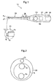
- a rod-type iontophoresis device 10 As shown in Figs. 1 and 2 , a rod-type iontophoresis device 10 according to the best mode is constituted by a working side electrode assembly 12 and a non-working side electrode assembly 14 each used for administering an ionic drug, a rod-like member 16 for integrally supporting them, and a DC electric power source 18 connected to the working side electrode assembly 12 and the non-working side electrode assembly 14 with opposite polarities.
- the working side electrode assembly 12 and the non-working side electrode assembly 14 are attached to the tip of the rod-like member 16, and the rod-like member 16 is detachably supported by the tip of a bar-like holding portion 20.
- the working side electrode assembly 12 and the non-working side electrode assembly 14 are exchangeable integrally with the rod-like member 16.
- a proximal end portion of the holding portion 20 opposite to the rod-like member 16 serves as a gripping portion 21 having a diameter large enough to be gripped by a human hand.
- the holding portion 20 has an irradiation optical system 26 including: an irradiation light source 22 composed of a light-emitting diode (LED) or a laser diode present inside the system; and an optical fiber 24 for irradiation for introducing light emitted from the irradiation light source 22 to a neighborhood of the rod-like member 16.
- the optical fiber 24 for irradiation is placed such that a tip thereof is adjacent to the rod-like member 16, and is adapted to emit, from the tip, irradiation light with which an affected area or the like of an organism at a position with which the working side electrode assembly 12 can contact is irradiated.
- the working side electrode assembly 12 and the non-working side electrode assembly 14 are connected to different polarities of the DC electric power source 18 through an electric power source circuit 28.
- the irradiation light source 22 is also connected to the DC electric power source 18 through a switch 23.
- An end portion of the rod-like member 16 on the side of the holding portion 20 is provided with a working side electrode terminal 32 to be connected to the working side electrode assembly 12 and a non-working side electrode terminal 34 to be connected to the non-working side electrode assembly 14.
- the working electrode terminal 32 and the non-working electrode terminal 34 are adapted to be connected to an electric power source side working electrode terminal 33 and an electric power source side non-working electrode terminal 35 on the side of the holding portion 20, respectively, when the rod-like member 16 is attached to the holding portion 20.
- the electric power source side working electrode terminal 33 and the electric power source side non-working electrode terminal 35 are further connected to the DC electric power source 30 placed outside through the electric power source circuit 28.
- the rod-like member 16 is a cylindrical member having a diameter smaller than that of the tip of the holding portion 20, and is adapted to be capable of: being attached by being threaded with a male screw portion 16A into a female screw portion 20A at the tip of the holding portion 20; and being detached by being rotated in the opposite direction.
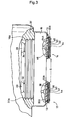
- Fig. 3 is an enlarged view showing that the working side electrode assembly 12 and the non-working side electrode assembly 14 are placed such that central axes thereof are in parallel with each other.
- the working side electrode assembly 12 is constituted by laminating a working side electrode 36, an electrolyte solution holding portion 38, a second ion exchange membrane 40, a drug solution holding portion 42, and a first ion exchange membrane 44 in this order from the side of the rod-like member 16, and is formed into a disk shape of about 2 to 6 mm in diameter.
- the working side electrode 36 is desirably constituted by a conductive paint applied to one surface of a base sheet 13 and blended with a nonmetal conductive filler such as a carbon paste.
- the working side electrode 36 can be constituted by a copper plate or a metal thin film, but a metal eluted from the plate or the thin film may transfer to an organism upon administration of a drug. Therefore, the working side electrode 36 is preferably nonmetallic.
- the electrolyte solution holding portion 38 is constituted by, for example, an electrolytic paint applied to the working side electrode 36.
- the electrolytic paint is a paint containing an electrolyte, and an electrolyte that is oxidized or reduced more easily than the electrolytic reaction of water (oxidation on a positive pole and reduction on a negative pole) is particularly preferably used.
- electrolyte include: medical agents such as ascorbic acid (vitamin C) and sodium ascorbate; and organic acids such as lactic acid, oxalic acid, malic acid, succinic acid, and fumaric acid and/or salts thereof.
- the use of such electrolyte can suppress the generation of an oxygen gas or a hydrogen gas.
- blending multiple kinds of electrolytes serving as a combination of buffer electrolyte solutions when dissolved in a solvent can suppress a change in pH during energization.
- the electrolytic paint is blended with a hydrophilic polymer such as polyvinyl alcohol, polyacrylic acid, polyacrylamide, or polyethylene glycol in order to improve the application property and film-forming property of the paint, and is blended with an appropriate amount of solvent such as water, ethanol, or propanol for adjusting the viscosity of the electrolytic paint.
- a hydrophilic polymer such as polyvinyl alcohol, polyacrylic acid, polyacrylamide, or polyethylene glycol
- solvent such as water, ethanol, or propanol
- the paint may be blended with an appropriate additional component such as a thickener, a thixotropic agent, a defoaming agent, a pigment, a flavor, or a coloring agent.
- the second ion exchange membrane 40 is formed by applying a second ion exchange paint to the electrolyte solution holding portion 38.
- the second ion exchange paint is a paint containing an ion exchange resin into which an ion exchange group using, as a counter ion, an ion having a conductivity type opposite to that of a drug ion in the drug solution holding portion 42 to be described later is introduced.
- the paint is blended with an anion exchange resin.
- the paint is blended with a cation exchange resin.
- the drug solution holding portion 42 is composed of a drug paint applied to the second ion exchange membrane 40.
- the paint is a paint containing a drug (including a precursor for the drug) whose drug component dissociates to plus or minus ions (drug ions) as a result of, for example, dissolution into a solvent such as water.
- a drug whose drug component dissociates to plus ions include lidocaine hydrochloride as an anesthetic drug and morphine hydrochloride as an anesthetic drug.
- Examples of a drug whose drug component dissociates to minus ions include ascorbic acid as a vitamin agent.
- the first ion exchange membrane 44 is formed of a first ion exchange paint applied to the drug solution holding portion 42.
- the first ion exchange paint is a paint containing an ion exchange resin into which an ion exchange group using, as a counter ion, an ion having the same conductivity type as that of the drug ion in the drug solution holding portion 42 is introduced.
- the paint is blended with an anion/cation exchange resin.
- a cation exchange group an exchange group using a cation as a counter ion
- An ion exchange resin obtained by introducing an anion exchange group such as a primary amino group, a secondary amino group, a tertiary amino group, a quaternary ammonium group, a pyridyl group, an imidazole group, a quaternary pyridinium group, or a quaternary imidazolium group into a polymer having a three-dimensional network structure similar to that in the case of the cation exchange resin can be used as the anion exchange resin without any limitation.
- an anion exchange group an exchange group using an anion as a counter ion
- the non-working side electrode assembly 14 is constituted by laminating a non-working side electrode 46, a second electrolyte solution holding portion 48, a third ion exchange membrane 50, a third electrolyte solution holding portion 52, and a fourth ion exchange membrane 54 in this order arranged on one surface side of a non-working base sheet 15, and is formed into a disk shape as in the case of the working side electrode assembly 12.
- the non-working side electrode 46 has the same constitution as that of the working side electrode 36 in the working electrode assembly 12, and the constitutions and components of the second electrolyte solution holding portion 48 and the third electrolyte solution holding portion 52 are the same as those of the electrolyte solution holding portion 38.
- the third ion exchange membrane 50 is formed of an ion exchange paint applied to the second electrolyte solution holding portion 48.
- the ion exchange paint is the same as the first ion exchange paint of which the first ion exchange membrane 44 is formed, and the third ion exchange membrane 50 functions as an ion exchange membrane similar to the first ion exchange membrane 44.
- the fourth ion exchange membrane 54 is formed of the same second ion exchange paint as that described above applied to the third electrolyte solution holding portion 52.
- the fourth ion exchange membrane 54 functions as an ion exchange membrane similar to the second ion exchange membrane 40.
- a working side electrode terminal plate 32A is arranged on the other surface of the base sheet 13, and conduction is established between the working side electrode terminal plate 32A and the working side electrode 36 of the working side electrode assembly 12 through a through-hole formed on the base sheet 13, and the working side electrode terminal plate 32A is connected to the working side electrode terminal 32 through the through-hole.
- a non-working side electrode terminal plate 34A is arranged on the other surface of the non-working side base sheet 15, and conduction is established between the non-working side electrode terminal plate 34A and the non-working side electrode 46 of the non-working side electrode assembly 14 through a through-hole formed on the non-working side base sheet 15, and the non-working side electrode terminal plate 34A is connected to the non-working side electrode terminal 34 through the through-hole.
- the first ion exchange membrane 44 and the fourth ion exchange membrane 54 at the tips of the working side electrode assembly 12 and the non-working side electrode assembly 14 are exposed so as to be capable of contacting with the side of an organism, respectively.
- the DC electric power source 18 is composed of, for example, an AC/DC converter, and the electric power source circuit 28 between the DC electric power source 18 and the electric power source side working electrode terminal 33 and between the DC electric power source 18 and the electric power source side non-working electrode terminal 35 is provided with a controller 56 for adjusting, out of a current value during energization and an energization time as administration time, at least the current value. As a result, each of the current value and the administration time can be adjusted in a certain range.
- a predetermined amount of spacing S is provided between the first ion exchange membrane 44 and the fourth ion exchange membrane 54 at each of the tips of the working side electrode assembly 12 and the non-working side electrode assembly 14 in order to prevent a current from directly flowing between the membranes upon energization.
- the spacing S has substantially the same size as that of the diameter of each of the first ion exchange membrane 44 and the fourth ion exchange membrane 54.
- the working side electrode assembly 12 and the non-working side electrode assembly 14 are attached such that central axes thereof are in parallel with each other.
- the present invention is not limited thereto.
- the working side electrode assembly 12 and the non-working side electrode assembly 14 may be placed such that central axes thereof intersect each other in a tip direction with an angle of 60° between the axes.
- the working side electrode assembly 12 and the non-working side electrode assembly 14 may be placed such that central axes thereof spread out to a tip direction.
- the working side electrode assembly 12 and the non-working side electrode assembly 14 are placed at the tip of the bar-like holding portion 20 with the spacing S between them. Therefore, when a drug solution is permeated into an affected area upon therapy or treatment outside a body (such as melanoma or skin cancer) or in a mouth (such as local anesthesia in odontotherapy, the therapy of stomatitis, or local anesthesia in an oral cavity), a doctor grips the gripping portion 21 to bring the first ion exchange membrane 44 at the tip of the working side electrode assembly 12 at the tip of the gripping portion 21 into close contact with the affected area and, at the same time, to bring the fourth ion exchange membrane 54 at the tip of the non-working side electrode assembly 14 into close contact with a mucous membrane or the like near the affected area for energization.
- a doctor grips the gripping portion 21 to bring the first ion exchange membrane 44 at the tip of the working side electrode assembly 12 at the tip of the gripping portion 21 into close contact with the affected area
- a target drug solution can be easily permeated into a target site in a pinpoint manner.
- the affected area When the affected area is placed in an oral cavity (that is, in the dark), the affected area in the dark can be illuminated by turning the switch 23 on to irradiate the area with light emitted from the tip of the optical fiber 24 for irradiation of the irradiation optical system 26.
- the working side electrode assembly 12 and the non-working side electrode assembly 14 can be detached together with the rod-like member 16 from the holding portion 20, so a drug solution can be easily exchanged.
- the rod-type iontophoresis device 10 can be used for, for example, therapy based on photodynamic therapy (PDT) as an anticancer remedy involving: applying a photosensitized reactive material to a cancer cell; and irradiating the material with light to cause the material to absorb the light.
- PDT photodynamic therapy
- the drug solution holding portion 42 in the working side electrode assembly 12 holds the photosensitized reactive material, and an affected area can be irradiated with light having a wavelength to be absorbed by the photosensitized reactive material and emitted from the irradiation light source 22 through the optical fiber 24 for irradiation.
- the working side electrode assembly 12 is shifted from the affected area after the photosensitized reactive material has been permeated into the affected area by iontophoresis. Then, light to be absorbed by the photosensitized reactive material is applied with the tip of the optical fiber 24 for irradiation as the position of the affected area.
- the affected area has a complicated shape (a two-dimensional convexoconcave figure)
- a picture is drawn by means of a lightproof insulating paint so that the shape remains on the surface of the first ion exchange membrane 44.
- Iontophoresis is performed in this state with the iontophoresis device pressed against a skin, whereby the photosensitized reactive material enters only the affected area and, at the same time, the lightproof insulating paint adheres to the periphery of the affected area. That is, the photosensitized reactive material does not enter a normal site and is not irradiated with light. In other words, double protection can be achieved.
- the tip of the holding portion 20 is provided with a ring-like light guide 62 to be connected to the optical fiber 24 for irradiation, and the working side electrode assembly 12 and the non-working side electrode assembly 14 are adapted to be capable of sliding back and forth to a cancer together with the rod-like member 16.
- the slide structure is identical to a knock structure in a ball-point pen for changing the position of the tip of the pen in two-stages: a projected position and a retracted position. Therefore, detailed description of the slide structure is omitted.
- the ring-like light guide 62 is constituted in such a manner that light to be emitted from the tip of the optical fiber 24 for irradiation connected to the light guide is introduced in a ring fashion and outputted from the inner peripheral surface of the guide.
- the tip of the light guide 62 at the projected position is adapted to coincide substantially with the tips of the working side electrode assembly 12 and the non-working side electrode assembly 14.
- the rod-like member 16 or the like is placed at the projected position upon administration of a drug solution, and the member or the like is placed at the retracted position after the administration of the drug solution.
- an affected area to which the drug solution has been administered is separated from the working side electrode assembly 12, and the gap between the area and the assembly is irradiated with light from the inner peripheral surface of the light guide 62.
- the holding portion 20 is provided with the optical fiber 24 for irradiation.
- the irradiation optical system 26 including the optical fiber 24 for irradiation is not needed when the device is not used for PDT or when there is no need to illuminate an affected area.
- the working side electrode assembly and the non-working side electrode assembly in the iontophoresis device are placed at the tip of the rod-like member, and the rod-like member is detachably supported by the tip of the bar-like holding portion.
- an anticancer agent is permeated by iontophoresis into a pinpoint such as the site of melanoma, whereby efficient therapy can be performed with little side effect.
- the drug solution can be exchanged by detaching the working side electrode assembly and the non-working side electrode assembly together with the rod-like member from the support member.
Abstract
Description
- The present invention relates to a rod-type iontophoresis device for administering a drug ion to an organism.
- Such iontophoresis device as described above is intended for permeating a drug solution into a skin or a mucous membrane, and has been conventionally used for a skin or mucous membrane having a relatively wide area of at least about 20 mm in diameter.
- On the other hand, in the case of, for example, the therapy/treatment in an oral cavity such as the therapy of stomatitis, local anesthesia in an oral cavity, or local anesthesia in odontotherapy, or the therapy of an integument such as melanoma or skin cancer, the direct injection of a drug solution into an affected area as a part (pinpoint) of an organism may increase a therapeutic effect.
- In such case, one prefers iontophoresis to injection for permeating a drug solution because the iontophoresis is non-invasive.
- Upon photodynamic therapy (PDT), a photosensitized reactive material is administered and irradiated with light, and an anticancer action is expected from the irradiation. However, a patient must be prevented from being irradiated with sunlight because the sensitizer circulates inhis or herbody. In addition, the sensitizer may circulate in a portion except an affected area to provide a side effect. Therefore, PDT has demanded the administration of a sensitizer only to an affected area.
- An object of the present invention is to provide an iontophoresis device suitably used for permeating a drug solution into a part of an organism that can be observed by a doctor from the outside in, for example, local anesthesia in an oral cavity or the therapy of melanoma.
- The above object can be achieved by the following various examples.
-
- (1) A rod-type iontophoresis device including: a working side electrode assembly and a non-working side electrode assembly each used for administering an ionic drug by iontophoresis; and a DC electric power source connected to the working electrode assembly and the non-working side electrode assembly with opposite polarities, characterized by including: a rod-like member for supporting the working side electrode assembly and the non-working side electrode assembly; and a bar-like holding portion for detachably supporting the rod-like member, the working side electrode assembly and the non-working side electrode assembly being placed at the tip of the rod-like member, and a predetermined amount of spacing being provided between the working electrode assembly and the non-working electrode assembly.
-
- (2) The rod-type iontophoresis device according to the above item (1), characterized in that the ionic drug is a photosensitized reactive material to be activated by absorbing light, and the holding portion has an irradiation optical system for applying light from the vicinity of the tip of the working side electrode assembly.
-
- (3) The rod-type iontophoresis device according to the above item (2), characterized in that the holding portion includes: a light source composed of a light-emitting diode or a laser diode for emitting light having a wavelength sensed by the photosensitized reactive material; and an optical fiber for irradiation for introducing light emitted from the light source to the rod-like member or a neighborhood thereof.
-
- (4) The rod-type iontophoresis device according to any one of the above items (1) to (3), characterized in that: the holding portion has an electric power source side working electrode terminal and an electric power source side non-working electrode terminal connected to the DC electric power source with opposite polarities through wiring from the DC electric power source, the wiring being housed in the holding portion; the rod-like member has on a proximal end of a side thereof detachable from the holding portion a working side electrode terminal and a non-working side electrode terminal which are connected to or are separated from the electric power source side working electrode terminal and the electric power source side non-working electrode terminal when attached to or detached from the holding portion; and the working side electrode teriminal and the non-working side electrode terminal are connected to a working side electrode and a non-working side electrode in the working side electrode assembly and the non-working side electrode assembly, respectively.
-
- (5) The rod-type iontophoresis device according to the above item (4), characterized in that a controller is provided in the holding portion, the controller being placed in an electric power source circuit between the electric power source side working electrode terminal and the electric power source side non-working electrode terminal and the DC electric power source for adjusting, out of a current value during energization and an energization time as administration time, at least the current value.
-
- (6) The rod-type iontophoresis device according to any one of the above items (1) to (5), characterized in that the working side electrode assembly and the non-working side electrode assembly are placed such that central axes thereof are in parallel with each other.
-
- (7) The rod-type iontophoresis device according to any one of the above items (1) to (5), characterized in that the working side electrode assembly and the non-working side electrode assembly are placed such that central axes thereof spread out to a tip direction.
-
- (8) The rod-type iontophoresis device according to any one of the above items (1) to (5), characterized in that the working side electrode assembly and the non-working side electrode assembly are placed such that central axes thereof intersect each other in a tip direction.
-
- (9) The rod-type iontophoresis device according to any one of the above items (1) to (8), characterized in that: the working side electrode assembly includes: the working side electrode connected to the DC electric power source having the same polarity as that of a charged ion of the ionic drug; an electrolyte solution holding portion holding an electrolyte solution, the electrolyte solution holding portion being placed on the front surface of the working side electrode; a second ion exchange membrane selecting an ion having a polarity opposite to that of the charged ion of the ionic drug, the second ion exchange membrane being placed on the front surface of the electrolyte solution holding portion; a drug solution holding portion holding the ionic drug, the drug solution holding portion being placed on the front surface of the second ion exchange membrane; and a first ion exchange membrane which is the ion exchange membrane selecting an ion having the same polarity as that of the charged ion of the ionic drug, the first ion exchange membrane being placed on the front surface of the drug solution holding portion; and the non-working side electrode assembly includes: the non-working side electrode connected to the DC electric power source having a polarity opposite to that of the charged ion of the ionic drug; a second electrolyte solution holding portion holding a second electrolyte solution, the second electrolyte solution holding portion being placed on the front surface of the non-working side electrode; a third ion exchange membrane selecting an ion having the same polarity as that of the charged ion of the ionic drug, the third ion exchange membrane being placed on the front surface of the second electrolyte solution holding portion; a third electrolyte solution holding portion holding a third electrolyte solution, the third electrolyte solution holding portion being placed on the front surface of the third ion exchange membrane; and a fourth ion exchange membrane which is the ion exchange membrane selecting an ion having a polarity opposite to that of the charged ion of the ionic drug, the fourth ion exchange membrane being placed on the front surface of the third electrolyte solution holding portion.
-
- [
Fig. 1 ] A plan view showing an iontophoresis device according to an embodiment of the present invention. - [
Fig. 2 ] An enlarged sectional view taken along the line II-II ofFig. 1 . - [
Fig. 3 ] An enlarged sectional view showing a main portion of each of a working side electrode assembly and a non-working side electrode assembly. - [
Fig. 4 ] A plan view showing another placement example of the working side electrode assembly and the non-working side electrode assembly. - [
Fig. 5 ] A plan view showing still another placement example of the working side electrode assembly and the non-working side electrode assembly. - [
Fig. 6 ] An enlarged front view showing a main portion of a rod-type iontophoresis device according to Example 2 of the present invention. - [
Fig. 7 ] A left side view of the rod-type iontophoresis device. - Hereinafter, the best mode for carrying out the present invention will be described in detail with reference to the drawings.
- As shown in
Figs. 1 and 2 , a rod-type iontophoresis device 10 according to the best mode is constituted by a workingside electrode assembly 12 and a non-workingside electrode assembly 14 each used for administering an ionic drug, a rod-like member 16 for integrally supporting them, and a DCelectric power source 18 connected to the workingside electrode assembly 12 and the non-workingside electrode assembly 14 with opposite polarities. - The working
side electrode assembly 12 and the non-workingside electrode assembly 14 are attached to the tip of the rod-like member 16, and the rod-like member 16 is detachably supported by the tip of a bar-like holding portion 20. As a result, the workingside electrode assembly 12 and the non-workingside electrode assembly 14 are exchangeable integrally with the rod-like member 16. A proximal end portion of theholding portion 20 opposite to the rod-like member 16 serves as a grippingportion 21 having a diameter large enough to be gripped by a human hand. - The
holding portion 20 has an irradiationoptical system 26 including: anirradiation light source 22 composed of a light-emitting diode (LED) or a laser diode present inside the system; and anoptical fiber 24 for irradiation for introducing light emitted from theirradiation light source 22 to a neighborhood of the rod-like member 16. As shown inFig. 2 , theoptical fiber 24 for irradiation is placed such that a tip thereof is adjacent to the rod-like member 16, and is adapted to emit, from the tip, irradiation light with which an affected area or the like of an organism at a position with which the workingside electrode assembly 12 can contact is irradiated. - The working
side electrode assembly 12 and the non-workingside electrode assembly 14 are connected to different polarities of the DCelectric power source 18 through an electricpower source circuit 28. Theirradiation light source 22 is also connected to the DCelectric power source 18 through aswitch 23. - An end portion of the rod-
like member 16 on the side of theholding portion 20 is provided with a workingside electrode terminal 32 to be connected to the workingside electrode assembly 12 and a non-workingside electrode terminal 34 to be connected to the non-workingside electrode assembly 14. - The working
electrode terminal 32 and thenon-working electrode terminal 34 are adapted to be connected to an electric power source side workingelectrode terminal 33 and an electric power source sidenon-working electrode terminal 35 on the side of theholding portion 20, respectively, when the rod-like member 16 is attached to theholding portion 20. - The electric power source side working
electrode terminal 33 and the electric power source sidenon-working electrode terminal 35 are further connected to the DC electric power source 30 placed outside through the electricpower source circuit 28. - The rod-
like member 16 is a cylindrical member having a diameter smaller than that of the tip of theholding portion 20, and is adapted to be capable of: being attached by being threaded with amale screw portion 16A into afemale screw portion 20A at the tip of theholding portion 20; and being detached by being rotated in the opposite direction. -
Fig. 3 is an enlarged view showing that the workingside electrode assembly 12 and the non-workingside electrode assembly 14 are placed such that central axes thereof are in parallel with each other. In addition, the workingside electrode assembly 12 is constituted by laminating a workingside electrode 36, an electrolytesolution holding portion 38, a secondion exchange membrane 40, a drugsolution holding portion 42, and a firstion exchange membrane 44 in this order from the side of the rod-like member 16, and is formed into a disk shape of about 2 to 6 mm in diameter. - The working
side electrode 36 is desirably constituted by a conductive paint applied to one surface of abase sheet 13 and blended with a nonmetal conductive filler such as a carbon paste. The workingside electrode 36 can be constituted by a copper plate or a metal thin film, but a metal eluted from the plate or the thin film may transfer to an organism upon administration of a drug. Therefore, the workingside electrode 36 is preferably nonmetallic. - The electrolyte
solution holding portion 38 is constituted by, for example, an electrolytic paint applied to the workingside electrode 36. The electrolytic paint is a paint containing an electrolyte, and an electrolyte that is oxidized or reduced more easily than the electrolytic reaction of water (oxidation on a positive pole and reduction on a negative pole) is particularly preferably used. Examples of such electrolyte include: medical agents such as ascorbic acid (vitamin C) and sodium ascorbate; and organic acids such as lactic acid, oxalic acid, malic acid, succinic acid, and fumaric acid and/or salts thereof. The use of such electrolyte can suppress the generation of an oxygen gas or a hydrogen gas. In addition, blending multiple kinds of electrolytes serving as a combination of buffer electrolyte solutions when dissolved in a solvent can suppress a change in pH during energization. - The electrolytic paint is blended with a hydrophilic polymer such as polyvinyl alcohol, polyacrylic acid, polyacrylamide, or polyethylene glycol in order to improve the application property and film-forming property of the paint, and is blended with an appropriate amount of solvent such as water, ethanol, or propanol for adjusting the viscosity of the electrolytic paint. The paint may be blended with an appropriate additional component such as a thickener, a thixotropic agent, a defoaming agent, a pigment, a flavor, or a coloring agent.
- The second
ion exchange membrane 40 is formed by applying a second ion exchange paint to the electrolytesolution holding portion 38. - The second ion exchange paint is a paint containing an ion exchange resin into which an ion exchange group using, as a counter ion, an ion having a conductivity type opposite to that of a drug ion in the drug
solution holding portion 42 to be described later is introduced. In the case where a drug whose drug component dissociates to plus drug ions is used in the drugsolution holding portion 42, the paint is blended with an anion exchange resin. On the other hand, in the case where a drug whose drug component dissociates to minus drug ions is used, the paint is blended with a cation exchange resin. - The drug
solution holding portion 42 is composed of a drug paint applied to the secondion exchange membrane 40. The paint is a paint containing a drug (including a precursor for the drug) whose drug component dissociates to plus or minus ions (drug ions) as a result of, for example, dissolution into a solvent such as water. Examples of a drug whose drug component dissociates to plus ions include lidocaine hydrochloride as an anesthetic drug and morphine hydrochloride as an anesthetic drug. Examples of a drug whose drug component dissociates to minus ions include ascorbic acid as a vitamin agent. - The first
ion exchange membrane 44 is formed of a first ion exchange paint applied to the drugsolution holding portion 42. The first ion exchange paint is a paint containing an ion exchange resin into which an ion exchange group using, as a counter ion, an ion having the same conductivity type as that of the drug ion in the drugsolution holding portion 42 is introduced. In the case where a drug whose drug component dissociates to plus/minus drug ions is used in the drugsolution holding portion 42, the paint is blended with an anion/cation exchange resin. - An ion exchange resin obtained by introducing a cation exchange group (an exchange group using a cation as a counter ion) such as a sulfonic group, a carboxylic group, or a phosphoric group into a polymer having a three-dimensional network structure such as a hydrocarbon-based resin (for example, a polystyrene resin or an acrylic resin) or a fluorine-based resin having a perfluorocarbon skeleton can be used as the cation exchange resin without any limitation.
- An ion exchange resin obtained by introducing an anion exchange group (an exchange group using an anion as a counter ion) such as a primary amino group, a secondary amino group, a tertiary amino group, a quaternary ammonium group, a pyridyl group, an imidazole group, a quaternary pyridinium group, or a quaternary imidazolium group into a polymer having a three-dimensional network structure similar to that in the case of the cation exchange resin can be used as the anion exchange resin without any limitation.
- The non-working
side electrode assembly 14 is constituted by laminating anon-working side electrode 46, a second electrolytesolution holding portion 48, a thirdion exchange membrane 50, a third electrolytesolution holding portion 52, and a fourthion exchange membrane 54 in this order arranged on one surface side of anon-working base sheet 15, and is formed into a disk shape as in the case of the workingside electrode assembly 12. - The
non-working side electrode 46 has the same constitution as that of the workingside electrode 36 in the workingelectrode assembly 12, and the constitutions and components of the second electrolytesolution holding portion 48 and the third electrolytesolution holding portion 52 are the same as those of the electrolytesolution holding portion 38. - Furthermore, the third
ion exchange membrane 50 is formed of an ion exchange paint applied to the second electrolytesolution holding portion 48. The ion exchange paint is the same as the first ion exchange paint of which the firstion exchange membrane 44 is formed, and the thirdion exchange membrane 50 functions as an ion exchange membrane similar to the firstion exchange membrane 44. - The fourth
ion exchange membrane 54 is formed of the same second ion exchange paint as that described above applied to the third electrolytesolution holding portion 52. The fourthion exchange membrane 54 functions as an ion exchange membrane similar to the secondion exchange membrane 40. - A working side
electrode terminal plate 32A is arranged on the other surface of thebase sheet 13, and conduction is established between the working sideelectrode terminal plate 32A and the workingside electrode 36 of the workingside electrode assembly 12 through a through-hole formed on thebase sheet 13, and the working sideelectrode terminal plate 32A is connected to the workingside electrode terminal 32 through the through-hole. - Similarly, a non-working side
electrode terminal plate 34A is arranged on the other surface of the non-workingside base sheet 15, and conduction is established between the non-working sideelectrode terminal plate 34A and thenon-working side electrode 46 of the non-workingside electrode assembly 14 through a through-hole formed on the non-workingside base sheet 15, and the non-working sideelectrode terminal plate 34A is connected to the non-workingside electrode terminal 34 through the through-hole. - The first
ion exchange membrane 44 and the fourthion exchange membrane 54 at the tips of the workingside electrode assembly 12 and the non-workingside electrode assembly 14 are exposed so as to be capable of contacting with the side of an organism, respectively. - The DC
electric power source 18 is composed of, for example, an AC/DC converter, and the electricpower source circuit 28 between the DCelectric power source 18 and the electric power source side workingelectrode terminal 33 and between the DCelectric power source 18 and the electric power source sidenon-working electrode terminal 35 is provided with acontroller 56 for adjusting, out of a current value during energization and an energization time as administration time, at least the current value. As a result, each of the current value and the administration time can be adjusted in a certain range. - A predetermined amount of spacing S is provided between the first
ion exchange membrane 44 and the fourthion exchange membrane 54 at each of the tips of the workingside electrode assembly 12 and the non-workingside electrode assembly 14 in order to prevent a current from directly flowing between the membranes upon energization. The spacing S has substantially the same size as that of the diameter of each of the firstion exchange membrane 44 and the fourthion exchange membrane 54. - In the embodiment, the working
side electrode assembly 12 and the non-workingside electrode assembly 14 are attached such that central axes thereof are in parallel with each other. However, the present invention is not limited thereto. For example, as shown inFig. 4 , the workingside electrode assembly 12 and the non-workingside electrode assembly 14 may be placed such that central axes thereof intersect each other in a tip direction with an angle of 60° between the axes. Alternatively, as shown inFig. 5 , the workingside electrode assembly 12 and the non-workingside electrode assembly 14 may be placed such that central axes thereof spread out to a tip direction. - In such embodiment, the working
side electrode assembly 12 and the non-workingside electrode assembly 14 are placed at the tip of the bar-like holding portion 20 with the spacing S between them. Therefore, when a drug solution is permeated into an affected area upon therapy or treatment outside a body (such as melanoma or skin cancer) or in a mouth (such as local anesthesia in odontotherapy, the therapy of stomatitis, or local anesthesia in an oral cavity), a doctor grips the grippingportion 21 to bring the firstion exchange membrane 44 at the tip of the workingside electrode assembly 12 at the tip of the grippingportion 21 into close contact with the affected area and, at the same time, to bring the fourthion exchange membrane 54 at the tip of the non-workingside electrode assembly 14 into close contact with a mucous membrane or the like near the affected area for energization. As a result, a target drug solution can be easily permeated into a target site in a pinpoint manner. When the affected area is placed in an oral cavity (that is, in the dark), the affected area in the dark can be illuminated by turning theswitch 23 on to irradiate the area with light emitted from the tip of theoptical fiber 24 for irradiation of the irradiationoptical system 26. - In addition, the working
side electrode assembly 12 and the non-workingside electrode assembly 14 can be detached together with the rod-like member 16 from the holdingportion 20, so a drug solution can be easily exchanged. - The rod-
type iontophoresis device 10 can be used for, for example, therapy based on photodynamic therapy (PDT) as an anticancer remedy involving: applying a photosensitized reactive material to a cancer cell; and irradiating the material with light to cause the material to absorb the light. - In this case, the following constitution is adopted. That is, the drug
solution holding portion 42 in the workingside electrode assembly 12 holds the photosensitized reactive material, and an affected area can be irradiated with light having a wavelength to be absorbed by the photosensitized reactive material and emitted from theirradiation light source 22 through theoptical fiber 24 for irradiation. In the case of PDT, the workingside electrode assembly 12 is shifted from the affected area after the photosensitized reactive material has been permeated into the affected area by iontophoresis. Then, light to be absorbed by the photosensitized reactive material is applied with the tip of theoptical fiber 24 for irradiation as the position of the affected area. - When the affected area has a complicated shape (a two-dimensional convexoconcave figure), a picture is drawn by means of a lightproof insulating paint so that the shape remains on the surface of the first
ion exchange membrane 44. Iontophoresis is performed in this state with the iontophoresis device pressed against a skin, whereby the photosensitized reactive material enters only the affected area and, at the same time, the lightproof insulating paint adheres to the periphery of the affected area. That is, the photosensitized reactive material does not enter a normal site and is not irradiated with light. In other words, double protection can be achieved. - Next, a rod-
type iontophoresis device 60 according to Example 2 shown inFigs. 6 and 7 will be described. - In the rod-
type iontophoresis device 60, the tip of the holdingportion 20 is provided with a ring-like light guide 62 to be connected to theoptical fiber 24 for irradiation, and the workingside electrode assembly 12 and the non-workingside electrode assembly 14 are adapted to be capable of sliding back and forth to a cancer together with the rod-like member 16. - The slide structure is identical to a knock structure in a ball-point pen for changing the position of the tip of the pen in two-stages: a projected position and a retracted position. Therefore, detailed description of the slide structure is omitted.
- The ring-like
light guide 62 is constituted in such a manner that light to be emitted from the tip of theoptical fiber 24 for irradiation connected to the light guide is introduced in a ring fashion and outputted from the inner peripheral surface of the guide. - The tip of the
light guide 62 at the projected position is adapted to coincide substantially with the tips of the workingside electrode assembly 12 and the non-workingside electrode assembly 14. - Accordingly, the rod-
like member 16 or the like is placed at the projected position upon administration of a drug solution, and the member or the like is placed at the retracted position after the administration of the drug solution. As a result, an affected area to which the drug solution has been administered is separated from the workingside electrode assembly 12, and the gap between the area and the assembly is irradiated with light from the inner peripheral surface of thelight guide 62. - In this example, the holding
portion 20 is provided with theoptical fiber 24 for irradiation. However, the irradiationoptical system 26 including theoptical fiber 24 for irradiation is not needed when the device is not used for PDT or when there is no need to illuminate an affected area. - In the present invention, the working side electrode assembly and the non-working side electrode assembly in the iontophoresis device are placed at the tip of the rod-like member, and the rod-like member is detachably supported by the tip of the bar-like holding portion. For example, an anticancer agent is permeated by iontophoresis into a pinpoint such as the site of melanoma, whereby efficient therapy can be performed with little side effect. In addition, the drug solution can be exchanged by detaching the working side electrode assembly and the non-working side electrode assembly together with the rod-like member from the support member.
Claims (9)
- A rod-type iontophoresis device comprising:a working side electrode assembly and a non-working side electrode assembly each used for administering an ionic drug by iontophoresis; anda DC electric power source connected to the working side electrode assembly and the non-working side electrode assembly with opposite polarities, characterized by comprising:a rod-like member for supporting the working side electrode assembly and the non-working side electrode assembly; anda bar-like holding portion for detachably supporting the rod-like member,the working side electrode assembly and the non-working side electrode assembly being disposed at a tip of the rod-like member, anda predetermined amount of spacing being provided between the working side electrode assembly and the non-working side electrode assembly.
- The rod-type iontophoresis device according to claim 1, characterized in that the ionic drug comprises a photosensitized reactive material to be activated by absorbing light, and the holding portion comprises an irradiation optical system for applying light from a vicinity of a tip of the working side electrode assembly.
- The rod-type iontophoresis device according to claim 2,
characterized in that the holding portion comprises:a light source comprising a light-emitting diode or a laser diode for emitting light having a wavelength sensed by the photosensitized reactive material; andan optical fiber for irradiation for introducing light emitted from the light source to the rod-like member or a neighborhood thereof. - The rod-type iontophoresis device according to any one of claims 1 to 3, characterized in that:the holding portion comprises an electric power source side working electrode terminal and an electric power source side non-working electrode terminal connected to the DC electric power source with opposite polarities through wiring from the DC electric power source, the wiring being housed in the holding portion;the rod-likemember comprises on a proximal endof a side thereof detachable from the holding portion a working side electrode terminal and a non-working side electrode terminal which are connected to or are separated from the electric power source side working electrode terminal and the electric power source side non-working electrode terminal when attached to or detached from the holding portion, andthe working side electrode teminal and the non-working side electrode terminal are connected to a working side electrode and a non-working side electrode in the working side electrode assembly and the non-working side electrode assembly, respectively.
- The rod-type iontophoresis device according to claim 4, characterized in that a controller is provided in the holdingportion, the controller being disposed in an electric power source circuit between the electric power source side working electrode terminal and the electric power source side non-working electrode terminal and the DC electric power source for adjusting, out of a current value during energization and an energization time as administration time, at least the current value.
- The rod-type iontophoresis device according to any one of claims 1 to 5, characterized in that the working side electrode assembly and the non-working side electrode assembly are disposed such that central axes thereof are in parallel with each other.
- The rod-type iontophoresis device according to any one of claims 1 to 5, characterized in that the working side electrode assembly and the non-working side electrode assembly are disposed such that central axes thereof spread out to a tip direction.
- The rod-type iontophoresis device according to any one of claims 1 to 5, characterized in that the working side electrode assembly and the non-working side electrode assembly are disposed such that central axes thereof intersect each other in a tip direction.
- The patch-type iontophoresis device according to any one of claims 1 to 8, characterized in that:the working side electrode assembly comprises:the working side electrode connected to the DC electric power source having the same polarity as that of a charged ion of the ionic drug;an electrolyte solution holding portion holding an electrolyte solution, the electrolyte solution holding portion being placed on a front surface of the working electrode;a second ion exchange membrane selecting an ion having a polarity opposite to that of the charged ion of the ionic drug, the second ion exchange membrane being placed on a front surface of the electrolyte solution holding portion;a drug solution holding portion holding the ionic drug, the drug solution holding portion being placed on a front surface of the second ion exchange membrane; anda first ion exchange membrane selecting an ion having the same polarity as that of the charged ion of the ionic drug, the first ion exchange membrane being placed on a front surface of the drug solution holding portion; andthe non-working side electrode assembly comprises:the non-working side electrode connected to the DC electric power source having a polarity opposite to that of the charged ion of the ionic drug;a second electrolyte solution holding portion holding a second electrolyte solution, the second electrolyte solution holding portion being placed on a front surface of the non-working electrode;a third ion exchange membrane selecting an ion having the same polarity as that of the charged ion of the ionic drug, the third ion exchange membrane being placed on a front surface of the second electrolyte solution holding portion;a third electrolyte solution holding portion holding a third electrolyte solution, the third electrolyte solution holding portion being placed on a front surface of the third ion exchange membrane; anda fourth ion exchange membrane which is the ion exchange membrane selecting an ion having a polarity opposite to that of the charged ion of the ionic drug, the fourth ion exchange membrane being placed on a front surface of the third electrolyte solution holding portion.
Applications Claiming Priority (2)
| Application Number | Priority Date | Filing Date | Title |
|---|---|---|---|
| JP2005268318 | 2005-09-15 | ||
| PCT/JP2006/318295 WO2007032446A1 (en) | 2005-09-15 | 2006-09-14 | Rod type iontophoresis device |
Publications (2)
| Publication Number | Publication Date |
|---|---|
| EP1925336A1 true EP1925336A1 (en) | 2008-05-28 |
| EP1925336A4 EP1925336A4 (en) | 2011-01-19 |
Family
ID=37865030
Family Applications (1)
| Application Number | Title | Priority Date | Filing Date |
|---|---|---|---|
| EP06798007A Withdrawn EP1925336A4 (en) | 2005-09-15 | 2006-09-14 | Rod type iontophoresis device |
Country Status (9)
| Country | Link |
|---|---|
| US (1) | US7890164B2 (en) |
| EP (1) | EP1925336A4 (en) |
| JP (1) | JPWO2007032446A1 (en) |
| KR (1) | KR20080047600A (en) |
| CN (1) | CN101252968A (en) |
| BR (1) | BRPI0616165A2 (en) |
| CA (1) | CA2619665A1 (en) |
| RU (1) | RU2008114490A (en) |
| WO (1) | WO2007032446A1 (en) |
Families Citing this family (40)
| Publication number | Priority date | Publication date | Assignee | Title |
|---|---|---|---|---|
| DE10205373B4 (en) * | 2002-02-09 | 2007-07-19 | Aloys Wobben | Fire protection |
| US20060095001A1 (en) * | 2004-10-29 | 2006-05-04 | Transcutaneous Technologies Inc. | Electrode and iontophoresis device |
| US20060135906A1 (en) * | 2004-11-16 | 2006-06-22 | Akihiko Matsumura | Iontophoretic device and method for administering immune response-enhancing agents and compositions |
| JP2006346368A (en) * | 2005-06-20 | 2006-12-28 | Transcutaneous Technologies Inc | Iontophoresis apparatus and manufacturing method |
| JP2007000342A (en) * | 2005-06-23 | 2007-01-11 | Transcutaneous Technologies Inc | Iontophoresis device for controlling quantity and time of dosing a plurality of medicaments |
| US8295922B2 (en) | 2005-08-08 | 2012-10-23 | Tti Ellebeau, Inc. | Iontophoresis device |
| US8386030B2 (en) * | 2005-08-08 | 2013-02-26 | Tti Ellebeau, Inc. | Iontophoresis device |
| US20070088332A1 (en) * | 2005-08-22 | 2007-04-19 | Transcutaneous Technologies Inc. | Iontophoresis device |
| WO2007023907A1 (en) * | 2005-08-24 | 2007-03-01 | Transcu Ltd. | Refrigeration-type electrode structure for iontophoresis |
| US20070048362A1 (en) * | 2005-08-29 | 2007-03-01 | Transcutaneous Technologies Inc. | General purpose electrolyte solution composition for iontophoresis |
| JPWO2007029611A1 (en) * | 2005-09-06 | 2009-03-19 | Tti・エルビュー株式会社 | Iontophoresis device |
| US20070112294A1 (en) * | 2005-09-14 | 2007-05-17 | Transcutaneous Technologies Inc. | Iontophoresis device |
| CA2619665A1 (en) | 2005-09-15 | 2007-03-22 | Tti Ellebeau, Inc. | Rod type iontophoresis device |
| WO2007032423A1 (en) * | 2005-09-16 | 2007-03-22 | Tti Ellebeau, Inc. | Catheter type iontophoresis apparatus |
| US20090299264A1 (en) * | 2005-09-28 | 2009-12-03 | Tti Ellebeau, Inc. | Electrode Assembly for Dry Type Iontophoresis |
| US20070232983A1 (en) * | 2005-09-30 | 2007-10-04 | Smith Gregory A | Handheld apparatus to deliver active agents to biological interfaces |
| JP4902543B2 (en) * | 2005-09-30 | 2012-03-21 | Tti・エルビュー株式会社 | Iontophoresis electrode structure having shape memory separator and iontophoresis device using the same |
| WO2007041115A1 (en) * | 2005-09-30 | 2007-04-12 | Tti Ellebeau Inc. | Method and system to detect malfunctions in an iontophoresis device that delivers active agents to biological interfaces |
| US20070078445A1 (en) * | 2005-09-30 | 2007-04-05 | Curt Malloy | Synchronization apparatus and method for iontophoresis device to deliver active agents to biological interfaces |
| EP1931417A2 (en) * | 2005-09-30 | 2008-06-18 | Transcutaneous Technologies Inc. | Transdermal drug delivery systems, devices, and methods employing novel pharmaceutical vehicles |
| US20070093787A1 (en) * | 2005-09-30 | 2007-04-26 | Transcutaneous Technologies Inc. | Iontophoresis device to deliver multiple active agents to biological interfaces |
| US20090187134A1 (en) * | 2005-09-30 | 2009-07-23 | Hidero Akiyama | Iontophoresis Device Controlling Amounts of a Sleep-Inducing Agent and a Stimulant to be Administered and Time at Which the Drugs are Administered |
| US20070078376A1 (en) * | 2005-09-30 | 2007-04-05 | Smith Gregory A | Functionalized microneedles transdermal drug delivery systems, devices, and methods |
| US20070135754A1 (en) * | 2005-09-30 | 2007-06-14 | Hidero Akiyama | Electrode assembly for iontophoresis for administering active agent enclosed in nanoparticle and iontophoresis device using the same |
| US20070197955A1 (en) * | 2005-10-12 | 2007-08-23 | Transcutaneous Technologies Inc. | Mucous membrane adhesion-type iontophoresis device |
| US20080033338A1 (en) * | 2005-12-28 | 2008-02-07 | Smith Gregory A | Electroosmotic pump apparatus and method to deliver active agents to biological interfaces |
| US20080033398A1 (en) * | 2005-12-29 | 2008-02-07 | Transcutaneous Technologies Inc. | Device and method for enhancing immune response by electrical stimulation |
| EP1965858A2 (en) * | 2005-12-30 | 2008-09-10 | Tti Ellebeau, Inc. | System and method for remote based control of an iontophoresis device |
| JP2010502293A (en) * | 2006-09-05 | 2010-01-28 | Tti・エルビュー株式会社 | Transdermal drug delivery system, apparatus and method using inductive power supply |
| JP5383497B2 (en) | 2006-12-01 | 2014-01-08 | Tti・エルビュー株式会社 | System and device for powering and / or controlling a device, for example a transdermal delivery device |
| WO2008144565A1 (en) * | 2007-05-18 | 2008-11-27 | Tti Ellebeau, Inc. | Transdermal delivery devices assuring an improved release of an active principle through a biological interface |
| JP2010187707A (en) * | 2007-06-12 | 2010-09-02 | Hokkaido Univ | Liposome preparation for iontophoresis comprising insulin encapsulated therein |
| WO2010099321A1 (en) * | 2009-02-26 | 2010-09-02 | The University Of North Carolina At Chapel Hill | Interventional drug delivery system and associated methods |
| US20100312168A1 (en) * | 2009-06-09 | 2010-12-09 | Yoshimasa Yoshida | Long life high capacity electrode, device, and method of manufacture |
| CN103338815A (en) * | 2011-08-01 | 2013-10-02 | 环爱心公司 | Optical treatment device for scalp and hair |
| CN103418080B (en) * | 2012-05-17 | 2014-10-22 | 纳米新能源(唐山)有限责任公司 | System using piezoelectric field for driving medicine iontophoresis |
| CN103418081B (en) * | 2012-05-24 | 2014-10-22 | 纳米新能源(唐山)有限责任公司 | System for drug iontophoresis driven by triboelectric field |
| CN106975150A (en) * | 2017-04-28 | 2017-07-25 | 河南长聚科技有限公司 | A kind of low frequency high efficiency mucous membrane of mouth disease therapeutic apparatus |
| JP6966115B1 (en) * | 2020-05-29 | 2021-11-10 | 義人 上田 | Iontophoresis periodontal ligament anesthesia machine |
| CN112516462B (en) * | 2020-11-24 | 2023-05-02 | 深圳霁因生物医药转化研究院 | Photoelectric combined instrument and photodynamic therapeutic apparatus |
Citations (5)
| Publication number | Priority date | Publication date | Assignee | Title |
|---|---|---|---|---|
| WO2003039620A2 (en) * | 2001-05-17 | 2003-05-15 | Transpharma Medical Ltd. | Integrated transdermal drug delivery system |
| FR2840533A1 (en) * | 2002-06-11 | 2003-12-12 | Guinot | Transcutaneous iontophoresis device, especially for activation of penetration into the skin of cosmetic preparations, has two moveable electrodes for application to the skin |
| WO2004028626A1 (en) * | 2002-09-24 | 2004-04-08 | Duret Francois | Bleaching device employing electro-optical and chemical means, which is intended, in particular, for use in the medical and dental field |
| US20040167458A1 (en) * | 2002-03-07 | 2004-08-26 | Ruxandra Draghia-Akli | Electrode assembly for constant-current electroporation and use |
| EP1566197A1 (en) * | 2002-11-27 | 2005-08-24 | Tokuyama Corporation | Iontophoresis apparatus |
Family Cites Families (262)
| Publication number | Priority date | Publication date | Assignee | Title |
|---|---|---|---|---|
| DE1003395B (en) | 1953-09-16 | 1957-02-28 | Sten Ingmar Wahlin | Dental care device to prevent the development of caries |
| US3520297A (en) | 1967-01-31 | 1970-07-14 | Chemway Corp | Iontophoretic toothbrush |
| DE2626294C3 (en) | 1976-06-11 | 1980-01-10 | Siemens Ag, 1000 Berlin Und 8000 Muenchen | Implantable dosing device |
| US4250878A (en) * | 1978-11-22 | 1981-02-17 | Motion Control, Inc. | Non-invasive chemical species delivery apparatus and method |
| US4352960A (en) | 1980-09-30 | 1982-10-05 | Baptist Medical Center Of Oklahoma, Inc. | Magnetic transcutaneous mount for external device of an associated implant |
| JPS5810066A (en) | 1981-07-10 | 1983-01-20 | 株式会社アドバンス | Plaster structure for ion tofuorese |
| CA1203286A (en) | 1982-06-16 | 1986-04-15 | Minnesota Mining And Manufacturing Company | Bioelectrode |
| US4856188A (en) | 1984-10-12 | 1989-08-15 | Drug Delivery Systems Inc. | Method for making disposable and/or replenishable transdermal drug applicators |
| US5224928A (en) | 1983-08-18 | 1993-07-06 | Drug Delivery Systems Inc. | Mounting system for transdermal drug applicator |
| US4640689A (en) * | 1983-08-18 | 1987-02-03 | Drug Delivery Systems Inc. | Transdermal drug applicator and electrodes therefor |
| US4708716A (en) | 1983-08-18 | 1987-11-24 | Drug Delivery Systems Inc. | Transdermal drug applicator |
| CA1262564A (en) | 1983-09-01 | 1989-10-31 | Minoru Sasaki | Iontophoresis device |
| US5135477A (en) | 1984-10-29 | 1992-08-04 | Medtronic, Inc. | Iontophoretic drug delivery |
| US4747819A (en) * | 1984-10-29 | 1988-05-31 | Medtronic, Inc. | Iontophoretic drug delivery |
| US4744787A (en) * | 1984-10-29 | 1988-05-17 | Medtronic, Inc. | Iontophoresis apparatus and methods of producing same |
| US4585652A (en) * | 1984-11-19 | 1986-04-29 | Regents Of The University Of Minnesota | Electrochemical controlled release drug delivery system |
| US4702732A (en) | 1984-12-24 | 1987-10-27 | Trustees Of Boston University | Electrodes, electrode assemblies, methods, and systems for tissue stimulation and transdermal delivery of pharmacologically active ligands |
| JPS622905A (en) | 1985-06-29 | 1987-01-08 | 株式会社 サンギ | Toothbrush |
| US4722726A (en) * | 1986-02-12 | 1988-02-02 | Key Pharmaceuticals, Inc. | Method and apparatus for iontophoretic drug delivery |
| US4752285B1 (en) | 1986-03-19 | 1995-08-22 | Univ Utah Res Found | Methods and apparatus for iontophoresis application of medicaments |
| IE60941B1 (en) | 1986-07-10 | 1994-09-07 | Elan Transdermal Ltd | Transdermal drug delivery device |
| US4725263A (en) * | 1986-07-31 | 1988-02-16 | Medtronic, Inc. | Programmable constant current source transdermal drug delivery system |
| US4786277A (en) | 1986-11-21 | 1988-11-22 | Trustees Of Boston University | Electrodes, electrode assemblies, methods, and systems for tissue stimulation |
| US4731049A (en) * | 1987-01-30 | 1988-03-15 | Ionics, Incorporated | Cell for electrically controlled transdermal drug delivery |
| AU609769B2 (en) | 1987-02-10 | 1991-05-09 | Drug Delivery Systems Inc. | Electrolytic transdermal delivery of proteins |
| US4940456A (en) | 1987-02-10 | 1990-07-10 | Dan Sibalis | Electrolytic transdermal delivery of proteins |
| CN87101867A (en) | 1987-03-09 | 1988-09-21 | 王龄 | Miniature ionic oral therapeutic device |
| US5080646A (en) | 1988-10-03 | 1992-01-14 | Alza Corporation | Membrane for electrotransport transdermal drug delivery |
| US4931046A (en) | 1987-05-15 | 1990-06-05 | Newman Martin H | Iontophoresis drug delivery system |
| US4944296A (en) | 1987-08-10 | 1990-07-31 | Hideo Suyama | Electronic toothbrush |
| US5496266A (en) | 1990-04-30 | 1996-03-05 | Alza Corporation | Device and method of iontophoretic drug delivery |
| US4927408A (en) | 1988-10-03 | 1990-05-22 | Alza Corporation | Electrotransport transdermal system |
| CA2001444C (en) * | 1988-10-28 | 2000-07-25 | Darrel F. Untereker | Iontophoresis electrode |
| US5006108A (en) * | 1988-11-16 | 1991-04-09 | Noven Pharmaceuticals, Inc. | Apparatus for iontophoretic drug delivery |
| US5240995A (en) | 1989-02-09 | 1993-08-31 | Alza Corporation | Electrotransport adhesive |
| US5374241A (en) | 1989-07-21 | 1994-12-20 | Iomed, Inc. | Electrodes for iontophoresis |
| EP0417963B1 (en) * | 1989-09-12 | 1994-08-03 | Hiroshi Hukuba | Toothbrush with voltage tester |
| US4950229A (en) * | 1989-09-25 | 1990-08-21 | Becton, Dickinson And Company | Apparatus for an electrode used for iontophoresis |
| US5320597A (en) | 1991-02-08 | 1994-06-14 | Becton, Dickinson And Company | Device and method for renewing electrodes during iontophoresis |
| US5167616A (en) | 1989-12-14 | 1992-12-01 | Alza Corporation | Iontophoretic delivery method |
| GB8928748D0 (en) * | 1989-12-20 | 1990-02-28 | Ici Plc | Solid state electrochromic devices |
| US5084008A (en) * | 1989-12-22 | 1992-01-28 | Medtronic, Inc. | Iontophoresis electrode |
| ES2082973T3 (en) | 1990-03-30 | 1996-04-01 | Alza Corp | DEVICE FOR PHARMACEUTICAL IONTOPHORETICAL ADMINISTRATION. |
| US6004309A (en) | 1990-03-30 | 1999-12-21 | Alza Corporation | Method and apparatus for controlled environment electrotransport |
| US5084006A (en) * | 1990-03-30 | 1992-01-28 | Alza Corporation | Iontopheretic delivery device |
| AU647103B2 (en) * | 1990-03-30 | 1994-03-17 | Alza Corporation | Iontophoretic delivery device |
| US5162043A (en) | 1990-03-30 | 1992-11-10 | Alza Corporation | Iontophoretic delivery device |
| DE9007277U1 (en) | 1990-04-04 | 1990-11-29 | Zimmermann, Silvia, 7981 Schlier, De | |
| US5236413B1 (en) | 1990-05-07 | 1996-06-18 | Andrew J Feiring | Method and apparatus for inducing the permeation of medication into internal tissue |
| DE4014913C2 (en) | 1990-05-10 | 1996-05-15 | Lohmann Therapie Syst Lts | Miniaturized transdermal therapeutic system for iontophoresis |
| FR2666805B1 (en) | 1990-09-14 | 1992-10-30 | Saint Gobain Vitrage Int | PROCESS FOR OBTAINING ELECTROCHROMIC WINDOWS. ELECTROCHROMIC WINDOWS. |
| JP3149950B2 (en) * | 1990-10-29 | 2001-03-26 | アルザ・コーポレーション | Dosing device by iontophoresis and method of hydrating the device |
| US5158537A (en) | 1990-10-29 | 1992-10-27 | Alza Corporation | Iontophoretic delivery device and method of hydrating same |
| US5443727A (en) | 1990-10-30 | 1995-08-22 | Minnesota Mining And Manufacturing Company | Articles having a polymeric shell and method for preparing same |
| US5224927A (en) | 1990-11-01 | 1993-07-06 | Robert Tapper | Iontophoretic treatment system |
| US5160790A (en) * | 1990-11-01 | 1992-11-03 | C. R. Bard, Inc. | Lubricious hydrogel coatings |
| WO1992015365A1 (en) | 1991-03-11 | 1992-09-17 | Alza Corporation | Iontophoretic delivery device and method of making same |
| US5218973A (en) | 1991-03-22 | 1993-06-15 | Staodyn, Inc. | Disposable wound treatment electrode |
| JP3040517B2 (en) | 1991-03-27 | 2000-05-15 | アール アンド アール ベンチャーズ株式会社 | Electrophoretic drug permeation device |
| US5405317A (en) * | 1991-05-03 | 1995-04-11 | Alza Corporation | Iontophoretic delivery device |
| US5203768A (en) * | 1991-07-24 | 1993-04-20 | Alza Corporation | Transdermal delivery device |
| US5464387A (en) | 1991-07-24 | 1995-11-07 | Alza Corporation | Transdermal delivery device |
| DE4238263A1 (en) | 1991-11-15 | 1993-05-19 | Minnesota Mining & Mfg | Adhesive comprising hydrogel and crosslinked polyvinyl:lactam - is used in electrodes for biomedical application providing low impedance and good mechanical properties when water and/or moisture is absorbed from skin |
| DE69213758T2 (en) | 1991-11-15 | 1997-05-07 | Minnesota Mining & Mfg | BIOMEDICAL ELECTRODE WITH TWO-PHASE CONSTRUCTIVE, SELF-ADHESIVE ADHESIVE |
| US5246417A (en) | 1991-12-11 | 1993-09-21 | Alza Corporation | Indicator for iontophoresis system |
| GB2265088B (en) | 1992-03-10 | 1996-02-07 | Kyosti Eero Antero Kontturi | Electrochemical device for drug delivery |
| US5310404A (en) | 1992-06-01 | 1994-05-10 | Alza Corporation | Iontophoretic delivery device and method of hydrating same |
| US5312326A (en) * | 1992-06-02 | 1994-05-17 | Alza Corporation | Iontophoretic drug delivery apparatus |
| DE69314634T2 (en) * | 1992-06-02 | 1998-05-20 | Alza Corp | DEVICE FOR IONTOPHORETIC ADMINISTRATION OF MEDICINES |
| US5380271A (en) * | 1992-09-24 | 1995-01-10 | Alza Corporation | Electrotransport agent delivery device and method |
| US5306235A (en) * | 1992-09-30 | 1994-04-26 | Becton Dickinson And Company | Failsafe iontophoresis drug delivery system |
| JP2542792B2 (en) | 1992-11-05 | 1996-10-09 | ベクトン・ディッキンソン・アンド・カンパニー | User-operated iontophoretic device |
| US5322520A (en) | 1992-11-12 | 1994-06-21 | Implemed, Inc. | Iontophoretic structure for medical devices |
| US5489624A (en) * | 1992-12-01 | 1996-02-06 | Minnesota Mining And Manufacturing Company | Hydrophilic pressure sensitive adhesives |
| JP3587537B2 (en) * | 1992-12-09 | 2004-11-10 | 株式会社半導体エネルギー研究所 | Semiconductor device |
| US5298017A (en) * | 1992-12-29 | 1994-03-29 | Alza Corporation | Layered electrotransport drug delivery system |
| ATE190233T1 (en) | 1992-12-31 | 2000-03-15 | Alza Corp | ELECTRIC TRANSPORT DEVICE |
| US5380272A (en) * | 1993-01-28 | 1995-01-10 | Scientific Innovations Ltd. | Transcutaneous drug delivery applicator |
| DE69426077T3 (en) * | 1993-05-25 | 2004-09-02 | Wyeth Holdings Corp. | ADJUVANTS FOR VACCINE AGAINST THE RESPIRATORY SYNCITIAL VIRUS |
| CA2126487C (en) * | 1993-06-23 | 2001-05-29 | Keiichiro Okabe | Iontophoresis device |
| US6377847B1 (en) * | 1993-09-30 | 2002-04-23 | Vyteris, Inc. | Iontophoretic drug delivery device and reservoir and method of making same |
| US5871460A (en) * | 1994-04-08 | 1999-02-16 | Alza Corporation | Electrotransport system with ion exchange material providing enhanced drug delivery |
| US5503632A (en) * | 1994-04-08 | 1996-04-02 | Alza Corporation | Electrotransport device having improved cathodic electrode assembly |
| DE69532503T2 (en) | 1994-06-17 | 2004-11-04 | Hisamitsu Pharmaceutical Co., Inc., Tosu | ELECTRODE FOR IONTOPHORESIS AND DEVICE THEREFOR |
| WO1996002232A1 (en) | 1994-07-13 | 1996-02-01 | Alza Corporation | Composition and method for enhancing transdermal electrotransport agent delivery |
| EP0783343A4 (en) * | 1994-08-22 | 1999-02-03 | Iomed Inc | Iontophoretic delivery device with integral hydrating means |
| US5645526A (en) | 1994-09-30 | 1997-07-08 | Becton Dickinson And Company | Apparatus and method for ensuring compatibility of a reusable iontophoretic controller with an iontophoretic patch |
| US5795321A (en) | 1994-09-30 | 1998-08-18 | Becton Dickinson And Company | Iontophoretic drug delivery system, including removable controller |
| US5551953A (en) | 1994-10-31 | 1996-09-03 | Alza Corporation | Electrotransport system with remote telemetry link |
| FR2729574B1 (en) | 1995-01-24 | 1997-07-04 | Sanofi Sa | IONOPHORESIS DEVICE FOR THE TRANSCUTANEOUS ADMINISTRATION OF AN ANIONIC OLIGOSACCHARIDE ACTIVE PRINCIPLE |
| EP0819016A1 (en) * | 1995-04-07 | 1998-01-21 | Novartis AG | Iontophoretic transdermal system for the administration of at least two substances |
| IE960312A1 (en) * | 1995-06-02 | 1996-12-11 | Alza Corp | An electrotransport delivery device with voltage boosting¹circuit |
| US6425892B2 (en) * | 1995-06-05 | 2002-07-30 | Alza Corporation | Device for transdermal electrotransport delivery of fentanyl and sufentanil |
| ATE248004T1 (en) | 1995-06-14 | 2003-09-15 | Hisamitsu Pharmaceutical Co | INTERFACE FOR IONTOPHORESIS |
| US5788666A (en) | 1995-06-15 | 1998-08-04 | Empi, Inc. | Iontophoresis electrode |
| US5840056A (en) | 1995-06-15 | 1998-11-24 | Empi, Inc. | Iontophoresis electrode |
| US6167301A (en) * | 1995-08-29 | 2000-12-26 | Flower; Ronald J. | Iontophoretic drug delivery device having high-efficiency DC-to-DC energy conversion circuit |
| CA2229872C (en) | 1995-08-31 | 2002-02-05 | Hisamitsu Pharmaceutical Co., Inc. | Iontophoresis system and its control process of current |
| JP3290864B2 (en) | 1995-08-31 | 2002-06-10 | 久光製薬株式会社 | Power supply for iontophoresis |
| US5814094A (en) | 1996-03-28 | 1998-09-29 | Becker; Robert O. | Iontopheretic system for stimulation of tissue healing and regeneration |
| EP0957979B1 (en) | 1995-09-29 | 2007-05-23 | Vyteris, Inc. | Low-cost electrodes for an iontophoretic device |
| US6678553B2 (en) | 1995-11-21 | 2004-01-13 | Intraabrain International Nv | Device for enhanced delivery of biologically active substances and compounds in an organism |
| JP3459724B2 (en) | 1996-03-17 | 2003-10-27 | 久光製薬株式会社 | Electrode device for iontophoresis |
| FR2747313B1 (en) | 1996-04-16 | 1998-06-05 | Lhd Lab Hygiene Dietetique | TRANSDERMAL MEDICINE DELIVERY DEVICE BY IONOPHORESIS |
| US6086572A (en) | 1996-05-31 | 2000-07-11 | Alza Corporation | Electrotransport device and method of setting output |
| WO1997047355A1 (en) | 1996-06-12 | 1997-12-18 | Alza Corporation | Reduction of skin sensitization in electrotransport drug delivery |
| EP0920345A4 (en) | 1996-06-19 | 2006-05-10 | Vyteris Inc | Iontophoretic delivery of cell adhesion inhibitors |
| US5941843A (en) | 1996-07-12 | 1999-08-24 | Empi, Inc. | Iontophoresis electrode |
| US6094594A (en) | 1996-08-14 | 2000-07-25 | Tapper; Robert | Hair removal system |
| US5738647A (en) | 1996-09-27 | 1998-04-14 | Becton Dickinson And Company | User activated iontophoretic device and method for activating same |
| US6350259B1 (en) * | 1996-09-30 | 2002-02-26 | Vyteris, Inc. | Selected drug delivery profiles using competing ions |
| US5800685A (en) | 1996-10-28 | 1998-09-01 | Cardiotronics Systems, Inc. | Electrically conductive adhesive hydrogels |
| FR2755372B1 (en) | 1996-11-07 | 1998-12-24 | Elf Aquitaine | IONOPHORESIS DEVICE COMPRISING AT LEAST ONE MEMBRANE ELECTRODE ASSEMBLY FOR THE TRANSCUTANEOUS ADMINISTRATION OF ACTIVE PRINCIPLES TO A SUBJECT |
| US6797276B1 (en) | 1996-11-14 | 2004-09-28 | The United States Of America As Represented By The Secretary Of The Army | Use of penetration enhancers and barrier disruption agents to enhance the transcutaneous immune response |
| US7033598B2 (en) * | 1996-11-19 | 2006-04-25 | Intrabrain International N.V. | Methods and apparatus for enhanced and controlled delivery of a biologically active agent into the central nervous system of a mammal |
| EP1008365A4 (en) | 1997-02-17 | 2004-11-17 | Kowa Co | Device for iontophoresis |
| US5991655A (en) | 1997-03-03 | 1999-11-23 | Drug Delivery Systems, Inc. | Iontophoretic drug delivery device and method of manufacturing the same |
| JP4079481B2 (en) | 1997-06-27 | 2008-04-23 | 久光製薬株式会社 | Device for transdermal or transmucosal drug delivery |
| US6228206B1 (en) | 1997-07-30 | 2001-05-08 | Drug Delivery Technologies, Inc. | Bonding agent composition containing conductive filler and method of bonding electrode to printed conductive trace with same |
| US6047208A (en) * | 1997-08-27 | 2000-04-04 | Becton, Dickinson And Company | Iontophoretic controller |
| JP3998765B2 (en) * | 1997-09-04 | 2007-10-31 | シャープ株式会社 | Method for manufacturing polycrystalline semiconductor layer and method for evaluating semiconductor device |
| US6918901B1 (en) | 1997-12-10 | 2005-07-19 | Felix Theeuwes | Device and method for enhancing transdermal agent flux |
| US6197324B1 (en) * | 1997-12-18 | 2001-03-06 | C. R. Bard, Inc. | System and methods for local delivery of an agent |
| JP4154017B2 (en) | 1997-12-30 | 2008-09-24 | 久光製薬株式会社 | Iontophoresis device and drug unit |
| ATE279232T1 (en) * | 1998-01-28 | 2004-10-15 | Alza Corp | IONTOPHORETIC ELECTRODE DEVICE WITH LOW INITIAL RESISTANCE |
| KR100550492B1 (en) * | 1998-01-28 | 2006-02-09 | 알자 코포레이션 | Electrochemically Reactive Cathodes for an Electrotransport Device |
| JPH11239621A (en) | 1998-02-25 | 1999-09-07 | Hisamitsu Pharmaceut Co Inc | Iontophoresis device |
| US6503231B1 (en) * | 1998-06-10 | 2003-01-07 | Georgia Tech Research Corporation | Microneedle device for transport of molecules across tissue |
| EP0970719A3 (en) * | 1998-07-08 | 2000-08-23 | Nitto Denko Corporation | Electrode structure |
| GB9815820D0 (en) | 1998-07-22 | 1998-09-16 | Secr Defence | Improvements relating to micro-machining |
| US6178353B1 (en) | 1998-07-27 | 2001-01-23 | Advanced Bionics Corporation | Laminated magnet keeper for implant device |
| DE69921489T2 (en) * | 1998-08-31 | 2005-10-27 | Johnson & Johnson Consumer Companies, Inc. | ELECTRIC TRANSPORT DEVICE WITH BLADE |
| JP3620703B2 (en) * | 1998-09-18 | 2005-02-16 | キヤノン株式会社 | Negative electrode material for secondary battery, electrode structure, secondary battery, and production method thereof |
| US6858018B1 (en) * | 1998-09-28 | 2005-02-22 | Vyteris, Inc. | Iontophoretic devices |
| TW429382B (en) * | 1998-11-06 | 2001-04-11 | Matsushita Electric Ind Co Ltd | Regulating resistor, semiconductor equipment and its production method |
| US6597946B2 (en) | 1998-11-09 | 2003-07-22 | Transpharma Ltd. | Electronic card for transdermal drug delivery and analyte extraction |
| US6611706B2 (en) | 1998-11-09 | 2003-08-26 | Transpharma Ltd. | Monopolar and bipolar current application for transdermal drug delivery and analyte extraction |
| US6596401B1 (en) | 1998-11-10 | 2003-07-22 | C. R. Bard Inc. | Silane copolymer compositions containing active agents |
| US6329488B1 (en) | 1998-11-10 | 2001-12-11 | C. R. Bard, Inc. | Silane copolymer coatings |
| FR2787729B1 (en) | 1998-12-29 | 2001-01-26 | Oreal | NANOCAPSULES BASED ON HYDRODISPERSIBLE ANIONIC POLYMERS, THEIR PREPARATION METHOD AND COSMETIC OR DERMATOLOGICAL COMPOSITIONS CONTAINING THEM |
| JP4499295B2 (en) * | 1999-01-28 | 2010-07-07 | サイト パルス サイエンシズ、インコーポレイテッド | Delivery of macromolecules into cells |
| US6317630B1 (en) | 1999-01-29 | 2001-11-13 | Yossi Gross | Drug delivery device |
| US6424862B1 (en) | 1999-02-10 | 2002-07-23 | Gmp Drug Delivery, Inc. | Iontophoresis electroporation and combination patches for local drug delivery to body tissues |
| JP4361153B2 (en) | 1999-02-10 | 2009-11-11 | Tti・エルビュー株式会社 | Iontophoresis device |
| JP2000229129A (en) | 1999-02-12 | 2000-08-22 | R & R Ventures Kk | Method for administering ionic drug by iontophoresis |
| JP2000237327A (en) | 1999-02-19 | 2000-09-05 | R & R Ventures Kk | Administration method of ionic medicine by iontophoresis |
| JP4361155B2 (en) | 1999-02-19 | 2009-11-11 | Tti・エルビュー株式会社 | Iontophoresis device |
| JP2000237328A (en) | 1999-02-22 | 2000-09-05 | R & R Ventures Kk | Iontophoresis apparatus |
| JP2000237329A (en) * | 1999-02-22 | 2000-09-05 | R & R Ventures Kk | Administration method of ionic medicine by iontophoresis |
| US6477410B1 (en) * | 2000-05-31 | 2002-11-05 | Biophoretic Therapeutic Systems, Llc | Electrokinetic delivery of medicaments |
| US7127285B2 (en) * | 1999-03-12 | 2006-10-24 | Transport Pharmaceuticals Inc. | Systems and methods for electrokinetic delivery of a substance |
| JP2000288097A (en) | 1999-04-06 | 2000-10-17 | R & R Ventures Kk | Iontophorese apparatus |
| JP2000288098A (en) | 1999-04-06 | 2000-10-17 | R & R Ventures Kk | Iontophorese apparatus |
| JP4410421B2 (en) | 1999-04-13 | 2010-02-03 | 久光製薬株式会社 | Iontophoresis device |
| US6855441B1 (en) * | 1999-04-14 | 2005-02-15 | Power Paper Ltd. | Functionally improved battery and method of making same |
| EP1171195B1 (en) * | 1999-04-16 | 2005-03-16 | Johnson & Johnson Consumer Companies, Inc. | Electrotransport delivery system comprising internal sensors |
| EP1171194A1 (en) | 1999-04-16 | 2002-01-16 | JOHNSON & JOHNSON CONSUMER COMPANIES, INC. | Drug delivery device comprising a dual chamber reservoir |
| JP2000316991A (en) | 1999-05-13 | 2000-11-21 | Hisamitsu Pharmaceut Co Inc | Electrode structural body for iontophoresis device and its manufacture |
| US6385488B1 (en) | 1999-05-20 | 2002-05-07 | Vyteris, Inc. | Circuits for increasing the reliability of an iontophoretic system |
| US6611707B1 (en) | 1999-06-04 | 2003-08-26 | Georgia Tech Research Corporation | Microneedle drug delivery device |
| DE60027720T2 (en) | 1999-06-08 | 2007-04-26 | Altea Therapeutics Corp. | APPARATUS FOR MICROPORING A BIOLOGICAL TISSUE THROUGH A FILM TISSUE INTERFACE DEVICE AND METHOD |
| US6312612B1 (en) | 1999-06-09 | 2001-11-06 | The Procter & Gamble Company | Apparatus and method for manufacturing an intracutaneous microneedle array |
| US6379324B1 (en) * | 1999-06-09 | 2002-04-30 | The Procter & Gamble Company | Intracutaneous microneedle array apparatus |
| US6256533B1 (en) | 1999-06-09 | 2001-07-03 | The Procter & Gamble Company | Apparatus and method for using an intracutaneous microneedle array |
| US6377848B1 (en) * | 1999-08-25 | 2002-04-23 | Vyteris, Inc. | Devices activating an iontophoretic delivery device |
| US6394994B1 (en) | 1999-08-27 | 2002-05-28 | Vyteris, Inc. | Method for testing the ability of an iontophoretic reservoir-electrode to deliver a medicament |
| JP4414517B2 (en) * | 1999-09-01 | 2010-02-10 | 久光製薬株式会社 | Device structure for iontophoresis |
| US6511463B1 (en) * | 1999-11-18 | 2003-01-28 | Jds Uniphase Corporation | Methods of fabricating microneedle arrays using sacrificial molds |
| US6358281B1 (en) | 1999-11-29 | 2002-03-19 | Epic Biosonics Inc. | Totally implantable cochlear prosthesis |
| US6421561B1 (en) | 1999-12-30 | 2002-07-16 | Birch Point Medical, Inc. | Rate adjustable drug delivery system |
| US7194801B2 (en) | 2000-03-24 | 2007-03-27 | Cymbet Corporation | Thin-film battery having ultra-thin electrolyte and associated method |
| WO2001093363A2 (en) | 2000-05-26 | 2001-12-06 | Covalent Associates, Inc. | Non-flammable electrolytes |
| US6565532B1 (en) | 2000-07-12 | 2003-05-20 | The Procter & Gamble Company | Microneedle apparatus used for marking skin and for dispensing semi-permanent subcutaneous makeup |
| US6496727B1 (en) | 2000-05-31 | 2002-12-17 | Becton, Dickinson And Company | Medicament-loaded transdermal reservoir and method for its formation |
| US6629968B1 (en) | 2000-06-30 | 2003-10-07 | Vyteris, Inc. | Shelf storage stable iontophoresis reservoir-electrode and iontophoretic system incorporating the reservoir-electrode |
| DE60142900D1 (en) | 2000-07-07 | 2010-10-07 | Corium Internat Inc | PREPARATION OF HYDROPHILIC PRESSURE-SENSITIVE ADHESIVES WITH OPTIMAL TONGUE CHARACTERISTICS |
| US6603987B2 (en) | 2000-07-11 | 2003-08-05 | Bayer Corporation | Hollow microneedle patch |
| US7914815B2 (en) | 2000-08-16 | 2011-03-29 | Encore Health, Llc | Method for delivery of pharmaceuticals for treating or preventing presbyopia |
| WO2002015960A2 (en) | 2000-08-21 | 2002-02-28 | The Cleveland Clinic Foundation | Microneedle array module and method of fabricating the same |
| US6533949B1 (en) * | 2000-08-28 | 2003-03-18 | Nanopass Ltd. | Microneedle structure and production method therefor |
| AU2001295032A1 (en) | 2000-09-08 | 2002-03-22 | Thomas J. Magnani | Iontophoretic apparatus |
| US6560483B1 (en) | 2000-10-18 | 2003-05-06 | Minnesota High-Tech Resources, Llc | Iontophoretic delivery patch |
| US6553255B1 (en) * | 2000-10-27 | 2003-04-22 | Aciont Inc. | Use of background electrolytes to minimize flux variability during iontophoresis |
| US6731977B2 (en) | 2001-01-22 | 2004-05-04 | Iomed, Inc. | Iontophoretic electrode with improved current distribution |
| US6663820B2 (en) | 2001-03-14 | 2003-12-16 | The Procter & Gamble Company | Method of manufacturing microneedle structures using soft lithography and photolithography |
| NZ528750A (en) | 2001-04-04 | 2005-10-28 | Alza Corp | Transdermal electrotransport delivery device including an antimicrobial compatible reservoir composition |
| US8206738B2 (en) | 2001-05-01 | 2012-06-26 | Corium International, Inc. | Hydrogel compositions with an erodible backing member |
| ES2587187T3 (en) | 2001-05-01 | 2016-10-21 | A. V. Topchiev Institute Of Petrochemical Synthesis | Biphasic water absorbent bioadhesive composition |
| US6767341B2 (en) | 2001-06-13 | 2004-07-27 | Abbott Laboratories | Microneedles for minimally invasive drug delivery |
| US20030065285A1 (en) * | 2001-07-23 | 2003-04-03 | Higuchi William I. | Method and apparatus for increasing flux during reverse iontophoresis |
| DE10140666C2 (en) * | 2001-08-24 | 2003-08-21 | Univ Braunschweig Tech | Process for producing a conductive structured polymer film and use of the process |
| US6881203B2 (en) * | 2001-09-05 | 2005-04-19 | 3M Innovative Properties Company | Microneedle arrays and methods of manufacturing the same |
| BR0213762A (en) * | 2001-10-31 | 2004-10-19 | R & R Ventures Inc | Iontophoresis device |
| DE60237554D1 (en) | 2001-12-19 | 2010-10-14 | Alza Corp | Container housing with integrated conductive area |
| US6908453B2 (en) | 2002-01-15 | 2005-06-21 | 3M Innovative Properties Company | Microneedle devices and methods of manufacture |
| US20050131336A1 (en) | 2002-01-24 | 2005-06-16 | Kenji Mori | Electrode structure |
| US6775570B2 (en) | 2002-02-04 | 2004-08-10 | Ceramatec, Inc. | Iontophoretic treatment device |
| US7047069B2 (en) | 2002-02-04 | 2006-05-16 | Ceramatec, Inc. | Iontophoretic fluid delivery device |
| US7392080B2 (en) | 2002-03-11 | 2008-06-24 | Altea Therapeutics Corporation | Transdermal drug delivery patch system, method of making same and method of using same |
| US6708050B2 (en) * | 2002-03-28 | 2004-03-16 | 3M Innovative Properties Company | Wireless electrode having activatable power cell |
| JP4033382B2 (en) | 2002-04-08 | 2008-01-16 | 久光製薬株式会社 | Insulin administration device |
| GB2390023A (en) | 2002-06-27 | 2003-12-31 | Kieron Loy | Iontophoretic hairbrush with handle return electrode |
| US6975902B2 (en) | 2002-06-28 | 2005-12-13 | Alza Corporation | Reservoir and a series of related reservoirs for use in an electrotransport drug delivery device and devices comprised thereof |
| US20060009730A2 (en) | 2002-07-29 | 2006-01-12 | Eemso, Inc. | Iontophoretic Transdermal Delivery of One or More Therapeutic Agents |
| US6994933B1 (en) * | 2002-09-16 | 2006-02-07 | Oak Ridge Micro-Energy, Inc. | Long life thin film battery and method therefor |
| GB2393860B (en) | 2002-09-27 | 2006-02-15 | Zap Wireless Technologies Ltd | Improvements relating to retention of rechargeable devices |
| JP2004188188A (en) | 2002-11-27 | 2004-07-08 | Tokuyama Corp | Device for iontophoresis |
| CA2729967C (en) | 2002-12-13 | 2018-01-16 | Schering-Plough Healthcare Products, Inc. | Use of a transdermal or transmucosal ingredient delivery device |
| AU2003289357A1 (en) | 2002-12-17 | 2004-07-09 | Asahi Kasei Chemicals Corporation | Electrode catalyst for oxygen reduction and gas diffusion electrode |
| JP2004202057A (en) | 2002-12-26 | 2004-07-22 | Tokuyama Corp | Ionic medicine encapsulation bag |
| DE10305831B4 (en) | 2003-02-12 | 2007-01-04 | Siemens Ag | diagnostic device |
| US6745071B1 (en) | 2003-02-21 | 2004-06-01 | Birch Point Medical, Inc. | Iontophoretic drug delivery system |
| US20040167459A1 (en) | 2003-02-21 | 2004-08-26 | Higuchi William I. | Methods and systems for controlling and/or increasing iontophoretic flux |
| US7551957B2 (en) | 2003-03-06 | 2009-06-23 | Bioelectronics Corp. | Electromagnetic therapy device and methods |
| MXPA05010497A (en) * | 2003-03-31 | 2005-11-16 | Alza Corp | Electrotransport device having a reservoir housing having a flexible conductive element. |
| WO2004091015A1 (en) | 2003-04-09 | 2004-10-21 | Graham Simpson Murray | Conductive polymer, conductive polymer compositions and their use |
| JP4241157B2 (en) | 2003-04-16 | 2009-03-18 | 株式会社アドバンテスト | Test equipment |
| US9278155B2 (en) | 2003-06-05 | 2016-03-08 | 3M Innovative Properties Company | Adhesive compositions, articles incorporating same and methods of manufacture |
| US8734421B2 (en) * | 2003-06-30 | 2014-05-27 | Johnson & Johnson Consumer Companies, Inc. | Methods of treating pores on the skin with electricity |
| US7477938B2 (en) | 2003-06-30 | 2009-01-13 | Johnson & Johnson Cosumer Companies, Inc. | Device for delivery of active agents to barrier membranes |
| US7507228B2 (en) | 2003-06-30 | 2009-03-24 | Johnson & Johnson Consumer Companies, Inc. | Device containing a light emitting diode for treatment of barrier membranes |
| US7480530B2 (en) | 2003-06-30 | 2009-01-20 | Johnson & Johnson Consumer Companies, Inc. | Device for treatment of barrier membranes |
| US20070139862A1 (en) | 2003-10-09 | 2007-06-21 | Kaneka Corporation | Electrode composite body, electrolyte, and redox capacitor |
| CA2546282A1 (en) * | 2003-11-13 | 2005-06-02 | Alza Corporation | System and method for transdermal delivery |
| JP2005222892A (en) | 2004-02-09 | 2005-08-18 | Toyota Motor Corp | Fuel cell system |
| AU2005327211A1 (en) | 2004-06-01 | 2006-08-17 | Microchips, Inc. | Devices and methods for measuring and enhancing drug or analyte transport to/from medical implant |
| AU2004320509A1 (en) | 2004-06-02 | 2005-12-22 | Darrel Dean Drinan | Use of electric fields to minimize rejection of implanted devices and materials |
| JP3979403B2 (en) | 2004-06-28 | 2007-09-19 | ソニー株式会社 | Image information processing apparatus and image information processing method |
| US20060095001A1 (en) | 2004-10-29 | 2006-05-04 | Transcutaneous Technologies Inc. | Electrode and iontophoresis device |
| US20060135906A1 (en) | 2004-11-16 | 2006-06-22 | Akihiko Matsumura | Iontophoretic device and method for administering immune response-enhancing agents and compositions |
| JP4297277B2 (en) | 2004-11-24 | 2009-07-15 | 日精樹脂工業株式会社 | Injection molding method |
| JP4728631B2 (en) | 2004-11-30 | 2011-07-20 | Tti・エルビュー株式会社 | Iontophoresis device |
| EP1820533B1 (en) | 2004-12-09 | 2011-11-02 | TTI ellebeau, Inc. | Ion-tophoretic apparatus |
| JP4731931B2 (en) | 2005-02-03 | 2011-07-27 | Tti・エルビュー株式会社 | Iontophoresis device |
| JP4793806B2 (en) | 2005-03-22 | 2011-10-12 | Tti・エルビュー株式会社 | Iontophoresis device |
| JP2006346368A (en) * | 2005-06-20 | 2006-12-28 | Transcutaneous Technologies Inc | Iontophoresis apparatus and manufacturing method |
| JP2007000342A (en) * | 2005-06-23 | 2007-01-11 | Transcutaneous Technologies Inc | Iontophoresis device for controlling quantity and time of dosing a plurality of medicaments |
| US8386030B2 (en) * | 2005-08-08 | 2013-02-26 | Tti Ellebeau, Inc. | Iontophoresis device |
| US8295922B2 (en) * | 2005-08-08 | 2012-10-23 | Tti Ellebeau, Inc. | Iontophoresis device |
| US20070060860A1 (en) * | 2005-08-18 | 2007-03-15 | Transcutaneous Technologies Inc. | Iontophoresis device |
| US20070088332A1 (en) * | 2005-08-22 | 2007-04-19 | Transcutaneous Technologies Inc. | Iontophoresis device |
| US20070048362A1 (en) * | 2005-08-29 | 2007-03-01 | Transcutaneous Technologies Inc. | General purpose electrolyte solution composition for iontophoresis |
| US20070112294A1 (en) | 2005-09-14 | 2007-05-17 | Transcutaneous Technologies Inc. | Iontophoresis device |
| JP4907135B2 (en) | 2005-09-14 | 2012-03-28 | Tti・エルビュー株式会社 | Iontophoresis device |
| CA2619665A1 (en) | 2005-09-15 | 2007-03-22 | Tti Ellebeau, Inc. | Rod type iontophoresis device |
| EP1931417A2 (en) * | 2005-09-30 | 2008-06-18 | Transcutaneous Technologies Inc. | Transdermal drug delivery systems, devices, and methods employing novel pharmaceutical vehicles |
| US20070078445A1 (en) * | 2005-09-30 | 2007-04-05 | Curt Malloy | Synchronization apparatus and method for iontophoresis device to deliver active agents to biological interfaces |
| WO2007041115A1 (en) * | 2005-09-30 | 2007-04-12 | Tti Ellebeau Inc. | Method and system to detect malfunctions in an iontophoresis device that delivers active agents to biological interfaces |
| US20070093787A1 (en) * | 2005-09-30 | 2007-04-26 | Transcutaneous Technologies Inc. | Iontophoresis device to deliver multiple active agents to biological interfaces |
| US20070083147A1 (en) * | 2005-09-30 | 2007-04-12 | Transcutaneous Technologies Inc. | Iontophoresis apparatus and method to deliver antibiotics to biological interfaces |
| WO2007041323A1 (en) * | 2005-09-30 | 2007-04-12 | Tti Ellebeau, Inc. | Iontophoretic delivery of vesicle-encapsulated active agents |
| US20070232983A1 (en) | 2005-09-30 | 2007-10-04 | Smith Gregory A | Handheld apparatus to deliver active agents to biological interfaces |
| JP2009509676A (en) * | 2005-09-30 | 2009-03-12 | Tti・エルビュー株式会社 | Iontophoretic delivery of active substances conjugated to nanoparticles |
| US20070135754A1 (en) | 2005-09-30 | 2007-06-14 | Hidero Akiyama | Electrode assembly for iontophoresis for administering active agent enclosed in nanoparticle and iontophoresis device using the same |
| US20070078376A1 (en) * | 2005-09-30 | 2007-04-05 | Smith Gregory A | Functionalized microneedles transdermal drug delivery systems, devices, and methods |
| US20070197955A1 (en) | 2005-10-12 | 2007-08-23 | Transcutaneous Technologies Inc. | Mucous membrane adhesion-type iontophoresis device |
| US20080033338A1 (en) * | 2005-12-28 | 2008-02-07 | Smith Gregory A | Electroosmotic pump apparatus and method to deliver active agents to biological interfaces |
| US20080033398A1 (en) * | 2005-12-29 | 2008-02-07 | Transcutaneous Technologies Inc. | Device and method for enhancing immune response by electrical stimulation |
| EP1965858A2 (en) | 2005-12-30 | 2008-09-10 | Tti Ellebeau, Inc. | System and method for remote based control of an iontophoresis device |
| JP2010502270A (en) | 2006-08-29 | 2010-01-28 | アルザ・コーポレーシヨン | Chemical electrotransport with hydration measurements in hydratable reservoirs |
| JP2010502293A (en) | 2006-09-05 | 2010-01-28 | Tti・エルビュー株式会社 | Transdermal drug delivery system, apparatus and method using inductive power supply |
| JP5383497B2 (en) | 2006-12-01 | 2014-01-08 | Tti・エルビュー株式会社 | System and device for powering and / or controlling a device, for example a transdermal delivery device |
-
2006
- 2006-09-14 CA CA002619665A patent/CA2619665A1/en not_active Abandoned
- 2006-09-14 CN CNA2006800314002A patent/CN101252968A/en active Pending
- 2006-09-14 BR BRPI0616165-0A patent/BRPI0616165A2/en not_active IP Right Cessation
- 2006-09-14 KR KR1020087008693A patent/KR20080047600A/en not_active Application Discontinuation
- 2006-09-14 WO PCT/JP2006/318295 patent/WO2007032446A1/en active Application Filing
- 2006-09-14 RU RU2008114490/14A patent/RU2008114490A/en not_active Application Discontinuation
- 2006-09-14 US US11/522,095 patent/US7890164B2/en not_active Expired - Fee Related
- 2006-09-14 JP JP2007535544A patent/JPWO2007032446A1/en active Pending
- 2006-09-14 EP EP06798007A patent/EP1925336A4/en not_active Withdrawn
Patent Citations (5)
| Publication number | Priority date | Publication date | Assignee | Title |
|---|---|---|---|---|
| WO2003039620A2 (en) * | 2001-05-17 | 2003-05-15 | Transpharma Medical Ltd. | Integrated transdermal drug delivery system |
| US20040167458A1 (en) * | 2002-03-07 | 2004-08-26 | Ruxandra Draghia-Akli | Electrode assembly for constant-current electroporation and use |
| FR2840533A1 (en) * | 2002-06-11 | 2003-12-12 | Guinot | Transcutaneous iontophoresis device, especially for activation of penetration into the skin of cosmetic preparations, has two moveable electrodes for application to the skin |
| WO2004028626A1 (en) * | 2002-09-24 | 2004-04-08 | Duret Francois | Bleaching device employing electro-optical and chemical means, which is intended, in particular, for use in the medical and dental field |
| EP1566197A1 (en) * | 2002-11-27 | 2005-08-24 | Tokuyama Corporation | Iontophoresis apparatus |
Non-Patent Citations (1)
| Title |
|---|
| See also references of WO2007032446A1 * |
Also Published As
| Publication number | Publication date |
|---|---|
| RU2008114490A (en) | 2009-10-20 |
| WO2007032446A1 (en) | 2007-03-22 |
| EP1925336A4 (en) | 2011-01-19 |
| BRPI0616165A2 (en) | 2011-06-07 |
| KR20080047600A (en) | 2008-05-29 |
| US7890164B2 (en) | 2011-02-15 |
| JPWO2007032446A1 (en) | 2009-03-19 |
| CA2619665A1 (en) | 2007-03-22 |
| US20070066932A1 (en) | 2007-03-22 |
| CN101252968A (en) | 2008-08-27 |
Similar Documents
| Publication | Publication Date | Title |
|---|---|---|
| EP1925336A1 (en) | Rod type iontophoresis device | |
| AU2006289888B2 (en) | Catheter type iontophoresis apparatus | |
| BG108737A (en) | Iontophoresis device | |
| KR100534512B1 (en) | Formulation for electrically assisted delivery of lidocaine and epinephrine | |
| JP2012501799A (en) | Systems, devices, and methods for driving and / or controlling devices such as transdermal delivery devices, for example | |
| CN111888641A (en) | Iontophoretic drug delivery device | |
| WO2013018974A1 (en) | Optical treatment device for scalp and hair | |
| JP2000288098A (en) | Iontophorese apparatus | |
| MX2008003387A (en) | Rod type iontophoresis device | |
| EP1925334A1 (en) | Iontophoresis device and power supply device for iontophoresis device | |
| MX2008003522A (en) | Catheter type iontophoresis apparatus | |
| KR101512513B1 (en) | Cosmetic container having iontophoresis introduction function | |
| JP2007135814A (en) | Dosing method of drug ion and pin type iontophoresis device | |
| CN211561091U (en) | Special acupuncture needle of traditional chinese medical science acupuncture and moxibustion | |
| JP2007089776A (en) | Low-frequency treating device | |
| JP4732881B2 (en) | Iontophoresis device | |
| JP2007044071A (en) | Iontophoresis device and miniaturized constant-current power supply device for iontophoresis device | |
| JP2000342697A (en) | Electrode structure for iontophoresis and current density measuring device | |
| JP2007075375A (en) | Iontophoresis device and power supply device for iontophoresis device | |
| AU2006280749A1 (en) | Method and device for managing use condition of medicine, and medicine injection device | |
| JP2007075374A (en) | Iontophoresis device and power supply device for iontophoresis device | |
| JP2007260275A (en) | Iontophoresis device and composition for iontophoresis administration | |
| MX2008003523A (en) | Iontophoresis device and power supply device for iontophoresis device | |
| JP2008110056A (en) | Electrode member and iontophoresis device including electrode member |
Legal Events
| Date | Code | Title | Description |
|---|---|---|---|
| PUAI | Public reference made under article 153(3) epc to a published international application that has entered the european phase |
Free format text: ORIGINAL CODE: 0009012 |
|
| 17P | Request for examination filed |
Effective date: 20080207 |
|
| AK | Designated contracting states |
Kind code of ref document: A1 Designated state(s): AT BE BG CH CY CZ DE DK EE ES FI FR GB GR HU IE IS IT LI LT LU LV MC NL PL PT RO SE SI SK TR |
|
| RAP1 | Party data changed (applicant data changed or rights of an application transferred) |
Owner name: TTI ELLEBEAU, INC. |
|
| RIN1 | Information on inventor provided before grant (corrected) |
Inventor name: NAKAYAMA, MIZUO,TTI ELLEBEAU, INC. Inventor name: MATSUMURA, AKIHIKO,TTI ELLEBEAU, INC. Inventor name: AKIYAMA, HIDERO,TTI ELLEBEAU, INC. Inventor name: MATSUMURA, TAKEHIKO,TTI ELLEBEAU, INC. |
|
| REG | Reference to a national code |
Ref country code: HK Ref legal event code: DE Ref document number: 1121080 Country of ref document: HK |
|
| A4 | Supplementary search report drawn up and despatched |
Effective date: 20101222 |
|
| STAA | Information on the status of an ep patent application or granted ep patent |
Free format text: STATUS: THE APPLICATION IS DEEMED TO BE WITHDRAWN |
|
| 18D | Application deemed to be withdrawn |
Effective date: 20110322 |