EP1916348A1 - A joining system for insulating panels - Google Patents
A joining system for insulating panels Download PDFInfo
- Publication number
- EP1916348A1 EP1916348A1 EP07118930A EP07118930A EP1916348A1 EP 1916348 A1 EP1916348 A1 EP 1916348A1 EP 07118930 A EP07118930 A EP 07118930A EP 07118930 A EP07118930 A EP 07118930A EP 1916348 A1 EP1916348 A1 EP 1916348A1
- Authority
- EP
- European Patent Office
- Prior art keywords
- connecting pin
- layer
- central portion
- insulating material
- joining system
- Prior art date
- Legal status (The legal status is an assumption and is not a legal conclusion. Google has not performed a legal analysis and makes no representation as to the accuracy of the status listed.)
- Granted
Links
- 238000005304 joining Methods 0.000 title claims abstract description 28
- 239000011810 insulating material Substances 0.000 claims abstract description 43
- 239000004567 concrete Substances 0.000 claims abstract description 41
- 238000004873 anchoring Methods 0.000 claims abstract description 7
- 230000035515 penetration Effects 0.000 claims description 7
- 239000000463 material Substances 0.000 claims description 2
- 238000009413 insulation Methods 0.000 description 5
- 238000003780 insertion Methods 0.000 description 4
- 230000037431 insertion Effects 0.000 description 4
- 238000000034 method Methods 0.000 description 3
- 239000011150 reinforced concrete Substances 0.000 description 3
- 238000009415 formwork Methods 0.000 description 2
- 238000004519 manufacturing process Methods 0.000 description 2
- 238000009423 ventilation Methods 0.000 description 2
- 229910000831 Steel Inorganic materials 0.000 description 1
- 238000005266 casting Methods 0.000 description 1
- 238000011156 evaluation Methods 0.000 description 1
- 238000012986 modification Methods 0.000 description 1
- 230000004048 modification Effects 0.000 description 1
- 238000012856 packing Methods 0.000 description 1
- 230000002787 reinforcement Effects 0.000 description 1
- 239000010959 steel Substances 0.000 description 1
Images


Classifications
-
- E—FIXED CONSTRUCTIONS
- E04—BUILDING
- E04C—STRUCTURAL ELEMENTS; BUILDING MATERIALS
- E04C2/00—Building elements of relatively thin form for the construction of parts of buildings, e.g. sheet materials, slabs, or panels
- E04C2/02—Building elements of relatively thin form for the construction of parts of buildings, e.g. sheet materials, slabs, or panels characterised by specified materials
- E04C2/04—Building elements of relatively thin form for the construction of parts of buildings, e.g. sheet materials, slabs, or panels characterised by specified materials of concrete or other stone-like material; of asbestos cement; of cement and other mineral fibres
- E04C2/049—Building elements of relatively thin form for the construction of parts of buildings, e.g. sheet materials, slabs, or panels characterised by specified materials of concrete or other stone-like material; of asbestos cement; of cement and other mineral fibres completely or partially of insulating material, e.g. cellular concrete or foamed plaster
-
- E—FIXED CONSTRUCTIONS
- E04—BUILDING
- E04C—STRUCTURAL ELEMENTS; BUILDING MATERIALS
- E04C2/00—Building elements of relatively thin form for the construction of parts of buildings, e.g. sheet materials, slabs, or panels
- E04C2/02—Building elements of relatively thin form for the construction of parts of buildings, e.g. sheet materials, slabs, or panels characterised by specified materials
- E04C2/04—Building elements of relatively thin form for the construction of parts of buildings, e.g. sheet materials, slabs, or panels characterised by specified materials of concrete or other stone-like material; of asbestos cement; of cement and other mineral fibres
- E04C2/044—Building elements of relatively thin form for the construction of parts of buildings, e.g. sheet materials, slabs, or panels characterised by specified materials of concrete or other stone-like material; of asbestos cement; of cement and other mineral fibres of concrete
-
- E—FIXED CONSTRUCTIONS
- E04—BUILDING
- E04C—STRUCTURAL ELEMENTS; BUILDING MATERIALS
- E04C2/00—Building elements of relatively thin form for the construction of parts of buildings, e.g. sheet materials, slabs, or panels
- E04C2/02—Building elements of relatively thin form for the construction of parts of buildings, e.g. sheet materials, slabs, or panels characterised by specified materials
- E04C2/04—Building elements of relatively thin form for the construction of parts of buildings, e.g. sheet materials, slabs, or panels characterised by specified materials of concrete or other stone-like material; of asbestos cement; of cement and other mineral fibres
- E04C2/06—Building elements of relatively thin form for the construction of parts of buildings, e.g. sheet materials, slabs, or panels characterised by specified materials of concrete or other stone-like material; of asbestos cement; of cement and other mineral fibres reinforced
-
- E—FIXED CONSTRUCTIONS
- E04—BUILDING
- E04C—STRUCTURAL ELEMENTS; BUILDING MATERIALS
- E04C2/00—Building elements of relatively thin form for the construction of parts of buildings, e.g. sheet materials, slabs, or panels
- E04C2/02—Building elements of relatively thin form for the construction of parts of buildings, e.g. sheet materials, slabs, or panels characterised by specified materials
- E04C2/26—Building elements of relatively thin form for the construction of parts of buildings, e.g. sheet materials, slabs, or panels characterised by specified materials composed of materials covered by two or more of groups E04C2/04, E04C2/08, E04C2/10 or of materials covered by one of these groups with a material not specified in one of the groups
- E04C2/284—Building elements of relatively thin form for the construction of parts of buildings, e.g. sheet materials, slabs, or panels characterised by specified materials composed of materials covered by two or more of groups E04C2/04, E04C2/08, E04C2/10 or of materials covered by one of these groups with a material not specified in one of the groups at least one of the materials being insulating
- E04C2/288—Building elements of relatively thin form for the construction of parts of buildings, e.g. sheet materials, slabs, or panels characterised by specified materials composed of materials covered by two or more of groups E04C2/04, E04C2/08, E04C2/10 or of materials covered by one of these groups with a material not specified in one of the groups at least one of the materials being insulating composed of insulating material and concrete, stone or stone-like material
-
- E—FIXED CONSTRUCTIONS
- E04—BUILDING
- E04C—STRUCTURAL ELEMENTS; BUILDING MATERIALS
- E04C2/00—Building elements of relatively thin form for the construction of parts of buildings, e.g. sheet materials, slabs, or panels
- E04C2/02—Building elements of relatively thin form for the construction of parts of buildings, e.g. sheet materials, slabs, or panels characterised by specified materials
- E04C2/04—Building elements of relatively thin form for the construction of parts of buildings, e.g. sheet materials, slabs, or panels characterised by specified materials of concrete or other stone-like material; of asbestos cement; of cement and other mineral fibres
- E04C2/044—Building elements of relatively thin form for the construction of parts of buildings, e.g. sheet materials, slabs, or panels characterised by specified materials of concrete or other stone-like material; of asbestos cement; of cement and other mineral fibres of concrete
- E04C2002/045—Building elements of relatively thin form for the construction of parts of buildings, e.g. sheet materials, slabs, or panels characterised by specified materials of concrete or other stone-like material; of asbestos cement; of cement and other mineral fibres of concrete with two parallel leaves connected by tie anchors
- E04C2002/046—Flat anchors
Definitions
- the present invention relates to a joining system for insulating panels.
- insulating panels prefabricated or produced directly at the building site generally comprise a first layer of concrete, also known as the inner crust, and a second layer of concrete, also known as the outer crust, between which a layer of insulating material is arranged.
- first layer of concrete also known as the inner crust
- second layer of concrete also known as the outer crust
- joining systems are used, suitable to join the first concrete layer to the second concrete layer in order to fix the insulating layer.
- the joining systems known in the prior art comprise a plurality of connecting pins suitable for passing completely through the layer of insulating material in a direction that is substantially orthogonal to the insulating panel and join the first concrete layer to the second concrete layer.
- the connecting pins usually have a threaded cylindrical body, which is pointed at a first end and provided with a flange at a second end, opposite to the first end.
- Joining systems of this type are, however, mostly suitable for predrilled insulating materials, i.e. that have been processed so as to create seats suitable to facilitate the insertion of the connecting pins.
- a purpose of the present invention is to provide a joining system for insulating panels that overcomes the drawbacks of the prior art described above; in particular, a purpose of the invention is to produce a joining system for insulating panels that does not necessarily require predrilling of the layer of insulating material and at the same time is easy and cheap to produce. Another purpose of the invention is to provide a joining system for insulating panels that is particularly simple, fast and effective to use.
- the present invention relates to a joining system for insulating panels comprising at least two layers of concrete and at least one layer of insulating material that is arranged between the two concrete layers; said joining system comprising a plurality of connecting pins, suitable for passing completely through the layer of insulating material in a direction that is substantially orthogonal to the insulating panel in order to join said layers; said joining system being characterized in that each connecting pin has a flattened shape between two substantially flat and parallel opposite faces, extends along an axis and comprises a narrow central portion, having a substantially constant cross-section, and two end portions joined continuously to the central portion and wider laterally with respect to the axis than the central portion so that said connecting pin is self-anchoring; at least a first end portion being provided with a pointed end.
- reference number 1 indicates an insulating panel that extends mainly along a longitudinal axis A and comprises a first concrete layer 2, a second concrete layer 3 and a layer of insulating material 4, arranged between the first concrete layer 2 and the second concrete layer 3.
- the first concrete layer 2 and second concrete layer 3 are preferably made of reinforced concrete and thus comprise a reinforcement 5 consisting of steel bars 6 buried in the concrete and appropriately shaped and connected to one another.
- the layer of insulating material 4 preferably consists of a plurality of prefabricated elements (in figure 1 only one element is illustrated) that have not been predrilled and are of a predefined thickness, selected according to the desired level of heat insulation to be obtained with the insulating panel 1.
- the prefabricated elements of the layer of insulating material 4 are preferably of the ventilated type, i.e. provided with internal ventilation ducts, in order to optimize the level of heat insulation of the insulating panel 1.
- the layer of insulating material 4 is packed between the first concrete layer 2 and the second concrete layer 3 by means of a joining system 7, which comprises a plurality of connecting pins 8 and is suitable for joining the first concrete layer 2 and the second concrete layer 3.
- Each connecting pin 8 extends substantially along an axis B and is of a length such as to pass completely, in use, through the layer of insulating material 4 in a direction that is substantially orthogonal to the axis A of the insulating panel 1 and to partially engage the first concrete layer 2 and the second concrete layer 3 so as to prevent any movement of one of the concrete layers 2 and 3 with respect to the layer of insulating material 4.
- each connecting pin 8 has an prismatic shape elongated along the axis B and comprises a first end portion 10a, provided with a tip 9, a second end portion 10b, opposite to the end portion 10a, and a narrow central portion 12 having a substantially rectangular shape and a substantially constant cross-section; the two end portions 10a and 10b are joined continuously without interruption by rounded and/or chamfered profiles to the central portion 12 and are wider laterally with respect to the axis B than the central portion 12 to make the connecting pin 8 self-anchoring; the end portions 10a and 10b diverge from the central portion 12 gradually.
- the connecting pin 8 is flattened between two substantially flat and parallel opposite faces 13, 14 defined respectively by an upper base and a lower base of the connecting pin 8; the faces 13, 14 are pointed towards the end portion 10a, remaining substantially parallel to one another, the thickness of each connecting pin 8 remaining constant along its entire length.
- the faces 13, 14 are joined by two lateral sides 15 having constant height.
- the sides 15 converge in the end portion 10a to form the tip 9.
- the thickness of the connecting pin 8 may be variable, possibly in the end portions 10a, 10b, in order to meet any particular structural requirements.
- the connecting pin 8 a particular self-anchoring characteristic, to ensure the firm anchorage of the concrete layers 2, 3.
- the use of a plurality of connecting pins 8 prevents any sliding movements of one or both of the concrete layers 2 and 3 in relation to the layer of insulating material 4 (movement in a direction parallel to the axis A), and separating movements of one of the concrete layers 2 and 3 with respect to the layer of insulating material 4 (movement along a direction orthogonal to the axis A).
- Each connecting pin 8 is provided with at least one graduated scale 16, for example a centimetre scale, arranged visibly on a surface 17 of the connecting pin 8 and extending in a direction that is substantially parallel to the axis B.
- the graduated scale 16 is arranged on the face 13 (i.e. the surface 17 is part of the face 13), but it is understood that the graduated scale 16 could instead be arranged on the opposite face 14, or on both faces 13, 14, and/or on a side 15.
- the purpose of the graduated scale 16 is to provide the level of penetration of the connecting pin 8 into the layer of insulating material 4, to enable the installer to immediately and accurately gauge the level of penetration of the connecting pin 8 into the layer of insulating material 4.
- the connecting pins 8 are made of a material with low heat conductivity, plastic for example, to guarantee adequate insulation.
- the connecting pin 8 comprises in the central portion 12, preferably near the end portion 10a, a pair of transversal teeth 22 that protrude from the connecting pin 8, for example from respective faces 13, 14 of the connecting pin 8, in a direction that is substantially transversal, and in particular substantially orthogonal, to the axis B of the connecting pin 8 in order to improve the anchorage of the connecting pin 8 inside the layer of insulating material 4.
- a first concrete casting is performed, preferably of reinforced concrete, in a formwork or containment panel (known in the prior art and not illustrated in the attached drawings) to produce the concrete layer 2; next, with the concrete layer 2 still fresh, the layer of insulating material 4 is placed on the freshly formed concrete layer 2.
- a plurality of connecting pins 8 are then inserted into the layer of insulating material 4 in a direction that is substantially orthogonal to said layer of insulating material 4 and to the axis A, so that the respective tips 9 penetrate into the prefabricated elements of the layer of insulating material 4.
- the connecting pins 8 are inserted between one prefabricated element and the other of the layer of insulating material 4, so that the connecting pins 8 do not interfere with the ventilation ducts inside the prefabricated elements.
- the connecting pins 8 are then pushed, even simply by hand, so as to pass completely through the layer of insulating material 4 so that the end portion 10a protrudes from the layer of insulating material 4 and penetrates the concrete layer 2 until it touches the formwork.
- the length of the connecting pin 8 is such that, in use, the central portion 12 passes completely through the layer of insulating material 4 and the end portions 10a and 10b respectively engage the concrete layers 2 and 3.
- the installer can easily verify whether the desired level of penetration has been achieved by using the graduated scale 16 provided on each connecting pin 8.
- the insertion of the connecting pins 8 into the layer of insulating material 4 may also be performed with the help of a template (known in the prior art and not illustrated), which facilitates the correct spacing between the connecting pins 8.
- the insulating panel 1 is ready for use.
- the present invention has the following advantages.
- the connecting pins 8 of the joining system 7 are self-anchoring thanks to their characteristic shape, which is however extremely simple and cheap to produce, and overcomes the need for the lengthy and expensive processes that are required in order to produce threaded connecting pins provided with flanges or anchoring means to prevent any movement of the concrete layers.
- the pointed shape of the connecting pin 8 facilitates its penetration into the prefabricated elements that make up the layer of insulating material 4 or between one prefabricated element and the other of the layer of insulating material 4, which generally has a relatively high degree of hardness, even if not predrilled; and the rounded and chamfered shape of the connecting pin 8 allows the connecting pin 8 to slide better inside the layer of insulating material 4 once said connecting pin 8 has penetrated (whether inserted into the individual prefabricated elements that make up the layer of insulating material 4 or inserted between one prefabricated element and the other of the layer of insulating material 4).
- the flattened shape with constant thickness of the connecting pin 8 also facilitates its insertion through the layer of insulating material 4 and in particular its insertion between one prefabricated element and the other of the layer of insulating material 4.
- the graduated scale 16 allows the operator to immediately gauge the level of penetration of the connecting pin 8 into the layer of insulating material 4. Said aspect is considerably advantageous for the user and prevents errors in the subjective evaluation of the level of penetration.
- teeth 22, if present, further improve the anchorage of the connecting pin 8 and in particular prevent the connecting pin 8 from coming out of the layer of insulating material 4 engaged by the teeth 22.
Abstract
Description
- The present invention relates to a joining system for insulating panels.
- As known in the building sector, insulating panels (prefabricated or produced directly at the building site) generally comprise a first layer of concrete, also known as the inner crust, and a second layer of concrete, also known as the outer crust, between which a layer of insulating material is arranged. To ensure the correct packing of the layer of insulating material between the two concrete layers, joining systems are used, suitable to join the first concrete layer to the second concrete layer in order to fix the insulating layer.
- The joining systems known in the prior art comprise a plurality of connecting pins suitable for passing completely through the layer of insulating material in a direction that is substantially orthogonal to the insulating panel and join the first concrete layer to the second concrete layer. The connecting pins usually have a threaded cylindrical body, which is pointed at a first end and provided with a flange at a second end, opposite to the first end.
- Joining systems of this type are, however, mostly suitable for predrilled insulating materials, i.e. that have been processed so as to create seats suitable to facilitate the insertion of the connecting pins.
- The need to have a predrilled insulation is clearly disadvantageous in terms of the longer time required to produce the insulating panels and in terms of the cost, since the process devoted exclusively to predrilling the insulating layer involves costs which are not negligible. Moreover, the production of connecting pins of the type described above is a relatively long and complex process, due to the presence of threads and flanges.
- A purpose of the present invention is to provide a joining system for insulating panels that overcomes the drawbacks of the prior art described above; in particular, a purpose of the invention is to produce a joining system for insulating panels that does not necessarily require predrilling of the layer of insulating material and at the same time is easy and cheap to produce. Another purpose of the invention is to provide a joining system for insulating panels that is particularly simple, fast and effective to use.
- In accordance with the aforesaid purposes, the present invention relates to a joining system for insulating panels comprising at least two layers of concrete and at least one layer of insulating material that is arranged between the two concrete layers; said joining system comprising a plurality of connecting pins, suitable for passing completely through the layer of insulating material in a direction that is substantially orthogonal to the insulating panel in order to join said layers; said joining system being characterized in that each connecting pin has a flattened shape between two substantially flat and parallel opposite faces, extends along an axis and comprises a narrow central portion, having a substantially constant cross-section, and two end portions joined continuously to the central portion and wider laterally with respect to the axis than the central portion so that said connecting pin is self-anchoring; at least a first end portion being provided with a pointed end.
- Further characteristics and advantages of the present invention will become clear from the following description of a non-limiting embodiment thereof, with reference to the drawings attached hereto, in which:
- figure 1 is a schematic perspective view, with parts shown in section and parts removed for the sake of clarity, of an insulating panel comprising the joining system according to the present invention;
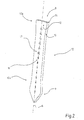
- figure 2 is a perspective view of a connecting pin that is part of the joining system in figure 1;
- figure 3 is a perspective view of a second embodiment of the connecting pin that is part of the joining system in figure 1; and
- figure 4 is a side view of the connecting pin in figure 3.
- In figure 1 reference number 1 indicates an insulating panel that extends mainly along a longitudinal axis A and comprises a first concrete layer 2, a second concrete layer 3 and a layer of
insulating material 4, arranged between the first concrete layer 2 and the second concrete layer 3. - The first concrete layer 2 and second concrete layer 3 are preferably made of reinforced concrete and thus comprise a
reinforcement 5 consisting of steel bars 6 buried in the concrete and appropriately shaped and connected to one another. - The layer of
insulating material 4 preferably consists of a plurality of prefabricated elements (in figure 1 only one element is illustrated) that have not been predrilled and are of a predefined thickness, selected according to the desired level of heat insulation to be obtained with the insulating panel 1. The prefabricated elements of the layer ofinsulating material 4 are preferably of the ventilated type, i.e. provided with internal ventilation ducts, in order to optimize the level of heat insulation of the insulating panel 1. The layer ofinsulating material 4 is packed between the first concrete layer 2 and the second concrete layer 3 by means of a joining system 7, which comprises a plurality of connectingpins 8 and is suitable for joining the first concrete layer 2 and the second concrete layer 3. - Each connecting
pin 8 extends substantially along an axis B and is of a length such as to pass completely, in use, through the layer ofinsulating material 4 in a direction that is substantially orthogonal to the axis A of the insulating panel 1 and to partially engage the first concrete layer 2 and the second concrete layer 3 so as to prevent any movement of one of the concrete layers 2 and 3 with respect to the layer ofinsulating material 4. - With reference to figure 2, each connecting
pin 8 has an prismatic shape elongated along the axis B and comprises afirst end portion 10a, provided with atip 9, asecond end portion 10b, opposite to theend portion 10a, and a narrowcentral portion 12 having a substantially rectangular shape and a substantially constant cross-section; the twoend portions central portion 12 and are wider laterally with respect to the axis B than thecentral portion 12 to make the connectingpin 8 self-anchoring; theend portions central portion 12 gradually. - The connecting
pin 8 is flattened between two substantially flat and parallelopposite faces pin 8; thefaces end portion 10a, remaining substantially parallel to one another, the thickness of each connectingpin 8 remaining constant along its entire length. - The
faces lateral sides 15 having constant height. Thesides 15 converge in theend portion 10a to form thetip 9. - It is, however, understood that the thickness of the connecting pin 8 (distance between the
faces 13, 14) may be variable, possibly in theend portions - The presence of the narrow
central portion 12 and the twowider end portions pins 8 prevents any sliding movements of one or both of the concrete layers 2 and 3 in relation to the layer of insulating material 4 (movement in a direction parallel to the axis A), and separating movements of one of the concrete layers 2 and 3 with respect to the layer of insulating material 4 (movement along a direction orthogonal to the axis A). - Each connecting
pin 8 is provided with at least one graduatedscale 16, for example a centimetre scale, arranged visibly on asurface 17 of the connectingpin 8 and extending in a direction that is substantially parallel to the axis B. In the example in figure 2, the graduatedscale 16 is arranged on the face 13 (i.e. thesurface 17 is part of the face 13), but it is understood that the graduatedscale 16 could instead be arranged on theopposite face 14, or on bothfaces side 15. - The purpose of the graduated
scale 16 is to provide the level of penetration of the connectingpin 8 into the layer ofinsulating material 4, to enable the installer to immediately and accurately gauge the level of penetration of the connectingpin 8 into the layer ofinsulating material 4. - The connecting
pins 8 are made of a material with low heat conductivity, plastic for example, to guarantee adequate insulation. - In figures 3 and 4, in which the same reference numbers are used to indicate parts that are similar to or the same as those already described, a second embodiment of the connecting
pin 8 that is part of the joining system 7 is illustrated. In this second embodiment, the connectingpin 8 comprises in thecentral portion 12, preferably near theend portion 10a, a pair oftransversal teeth 22 that protrude from the connectingpin 8, for example fromrespective faces pin 8, in a direction that is substantially transversal, and in particular substantially orthogonal, to the axis B of the connectingpin 8 in order to improve the anchorage of the connectingpin 8 inside the layer ofinsulating material 4. - The use of the joining system 7 with the connecting
pins 8 according to both of the embodiments described above, during the production of the insulating panel 1 is as follows. - A first concrete casting is performed, preferably of reinforced concrete, in a formwork or containment panel (known in the prior art and not illustrated in the attached drawings) to produce the concrete layer 2; next, with the concrete layer 2 still fresh, the layer of
insulating material 4 is placed on the freshly formed concrete layer 2. A plurality of connectingpins 8 are then inserted into the layer ofinsulating material 4 in a direction that is substantially orthogonal to said layer ofinsulating material 4 and to the axis A, so that therespective tips 9 penetrate into the prefabricated elements of the layer ofinsulating material 4. Alternatively, in particular in the case in which prefabricated elements of the ventilated type are used, the connectingpins 8 are inserted between one prefabricated element and the other of the layer ofinsulating material 4, so that the connectingpins 8 do not interfere with the ventilation ducts inside the prefabricated elements. - The connecting
pins 8 are then pushed, even simply by hand, so as to pass completely through the layer ofinsulating material 4 so that theend portion 10a protrudes from the layer ofinsulating material 4 and penetrates the concrete layer 2 until it touches the formwork. The length of the connectingpin 8 is such that, in use, thecentral portion 12 passes completely through the layer ofinsulating material 4 and theend portions scale 16 provided on each connectingpin 8. The insertion of the connectingpins 8 into the layer ofinsulating material 4 may also be performed with the help of a template (known in the prior art and not illustrated), which facilitates the correct spacing between the connectingpins 8. - Once the connecting
pins 8 have been inserted, another layer of concrete is cast, preferably reinforced concrete, on the layer ofinsulating material 4 to produce the concrete layer 3. - When the two layers are completely dry, the insulating panel 1 is ready for use.
- The present invention has the following advantages.
- Firstly, the connecting
pins 8 of the joining system 7 are self-anchoring thanks to their characteristic shape, which is however extremely simple and cheap to produce, and overcomes the need for the lengthy and expensive processes that are required in order to produce threaded connecting pins provided with flanges or anchoring means to prevent any movement of the concrete layers. - Secondly, the pointed shape of the connecting
pin 8 facilitates its penetration into the prefabricated elements that make up the layer ofinsulating material 4 or between one prefabricated element and the other of the layer ofinsulating material 4, which generally has a relatively high degree of hardness, even if not predrilled; and the rounded and chamfered shape of the connectingpin 8 allows the connectingpin 8 to slide better inside the layer of insulatingmaterial 4 once said connectingpin 8 has penetrated (whether inserted into the individual prefabricated elements that make up the layer ofinsulating material 4 or inserted between one prefabricated element and the other of the layer of insulating material 4). - The flattened shape with constant thickness of the connecting
pin 8 also facilitates its insertion through the layer ofinsulating material 4 and in particular its insertion between one prefabricated element and the other of the layer ofinsulating material 4. - Thirdly, the graduated
scale 16 allows the operator to immediately gauge the level of penetration of the connectingpin 8 into the layer ofinsulating material 4. Said aspect is considerably advantageous for the user and prevents errors in the subjective evaluation of the level of penetration. - Lastly, the
teeth 22, if present, further improve the anchorage of the connectingpin 8 and in particular prevent the connectingpin 8 from coming out of the layer of insulatingmaterial 4 engaged by theteeth 22. - It will be apparent that other changes and modifications may be made to the joining system for insulation panels described and illustrated herein without departing from the scope of the invention in accordance with the claims.
Claims (11)
- Joining system (7) for insulating panels (1) comprising at least two concrete layers (2, 3) and at least one layer of insulating material (4) arranged between the two concrete layers (2, 3); said joining system (7) comprising a plurality of connecting pins (8), suitable for passing completely through the layer of insulating material (4) in a direction that is substantially orthogonal to the insulating panel (1) in order to join said concrete layers (2, 3); said joining system (7) being characterized in that each connecting pin (8) has a flattened shape between two opposite and substantially flat and parallel faces (13, 14), extends along an axis (B) and is provided with a narrow central portion (12), having a substantially constant cross-section, and two end portions (10a, 10b) joined continuously to the central portion (12) and wider laterally with respect to the axis (B) than the central portion (12) so that said connecting pin (8) is self-anchoring; at least a first end portion (10a) being provided with a tip (9).
- System according to claim 1, characterized in that said opposite faces (13, 14) of each connecting pin (8) are pointed towards the first end portion (10a) and substantially parallel to one another.
- System according to claim 1 or 2, characterized in that the end portions (10a, 10b) of each connecting pin (8) are joined to the central portion (12) by rounded and/or chamfered profiles.
- System according to any of the previous claims, characterized in that the central portion (12) of each connecting pin (8) is substantially rectangular in shape and the end portions (10a, 10b) diverge from the central portion (12) gradually.
- System according to any of the previous claims, characterized in that the thickness of each connecting pin (8) remains constant along the entire length thereof.
- System according to any of the previous claims, characterized in that each connecting pin (8) is provided with a graduated scale (16) arranged visibly on a surface (17) of the connecting pin (8) to gauge the level of penetration into the layer of insulating material (4).
- System according to the previous claim, characterized in that the graduated scale (16) extends substantially parallel to the axis (B).
- Joining system according to claim 6 or 7, characterized in that the graduated scale (16) is a centimetre scale.
- Joining system according to any of the previous claims, characterized in that the connecting pins (8) are made of material with low heat conductivity.
- Joining system according to any of the previous claims, characterized in that the central portion (12) of each connecting pin (8) comprises a pair of transversal teeth (22), each of which protrudes from the connecting pin (8) in a substantially transversal direction in relation to the axis (B) of the connecting pin (8).
- Joining system according to claim 10, characterized in that the teeth (22) protrude from respective faces (13, 14) of the connecting pin (8).
Applications Claiming Priority (1)
| Application Number | Priority Date | Filing Date | Title |
|---|---|---|---|
| ITMI20060361 ITMI20060361U1 (en) | 2006-10-20 | 2006-10-20 | CONNECTION SYSTEM FOR INSULATING PANELS |
Publications (2)
| Publication Number | Publication Date |
|---|---|
| EP1916348A1 true EP1916348A1 (en) | 2008-04-30 |
| EP1916348B1 EP1916348B1 (en) | 2016-05-25 |
Family
ID=38982462
Family Applications (1)
| Application Number | Title | Priority Date | Filing Date |
|---|---|---|---|
| EP07118930.2A Active EP1916348B1 (en) | 2006-10-20 | 2007-10-19 | A joining system for insulating panels |
Country Status (3)
| Country | Link |
|---|---|
| EP (1) | EP1916348B1 (en) |
| ES (1) | ES2588202T3 (en) |
| IT (1) | ITMI20060361U1 (en) |
Cited By (3)
| Publication number | Priority date | Publication date | Assignee | Title |
|---|---|---|---|---|
| FR2939817A1 (en) * | 2008-12-11 | 2010-06-18 | Adrien Sarnari | Prefabricated elementary block for constructing e.g. outer insulating wall of building, has connection elements connecting reinforcement structures to fix inner bearing wall and outer protective shell to maintain constant transversal gap |
| WO2011028882A1 (en) * | 2009-09-02 | 2011-03-10 | 21St Century Structures, Llc | Embedded height adjustment mechanism for double-wall building panels |
| IT201700034762A1 (en) * | 2017-03-29 | 2018-09-29 | Anton Massimo Galluccio | REINFORCEMENT PANEL FOR REINFORCED CONCRETE STRUCTURES |
Citations (7)
| Publication number | Priority date | Publication date | Assignee | Title |
|---|---|---|---|---|
| US2653469A (en) * | 1948-06-12 | 1953-09-29 | Patrick J Callan | Building wall construction |
| BE898653A (en) * | 1984-01-11 | 1984-05-02 | Cbr Cementbedrijven Nv | Tie connecting concrete panels with insulation between - has hooked ends, one shaped to permit pressing through insulation at manufacture |
| DD245919A1 (en) * | 1986-02-10 | 1987-05-20 | Potsdam Landbauprojekt | CONNECTING ELEMENT FOR CONSTRUCTION CONSTRUCTIONS |
| GB2268761A (en) * | 1992-07-14 | 1994-01-19 | Ensor Metal Products Limited | Wall tie |
| US5519973A (en) * | 1993-08-17 | 1996-05-28 | H.K. Composites, Inc. | Highly insulative connector rods and methods for their manufacture and use in highly insulated composite walls |
| EP1321681A1 (en) * | 2001-12-19 | 2003-06-25 | Werner Rüdel | Device for fixing an article to an object and method for fixing it to an object |
| GB2404385A (en) * | 2003-06-28 | 2005-02-02 | Kwok Pun Chan | Wall tie with distal mortar engaging formations |
-
2006
- 2006-10-20 IT ITMI20060361 patent/ITMI20060361U1/en unknown
-
2007
- 2007-10-19 EP EP07118930.2A patent/EP1916348B1/en active Active
- 2007-10-19 ES ES07118930.2T patent/ES2588202T3/en active Active
Patent Citations (7)
| Publication number | Priority date | Publication date | Assignee | Title |
|---|---|---|---|---|
| US2653469A (en) * | 1948-06-12 | 1953-09-29 | Patrick J Callan | Building wall construction |
| BE898653A (en) * | 1984-01-11 | 1984-05-02 | Cbr Cementbedrijven Nv | Tie connecting concrete panels with insulation between - has hooked ends, one shaped to permit pressing through insulation at manufacture |
| DD245919A1 (en) * | 1986-02-10 | 1987-05-20 | Potsdam Landbauprojekt | CONNECTING ELEMENT FOR CONSTRUCTION CONSTRUCTIONS |
| GB2268761A (en) * | 1992-07-14 | 1994-01-19 | Ensor Metal Products Limited | Wall tie |
| US5519973A (en) * | 1993-08-17 | 1996-05-28 | H.K. Composites, Inc. | Highly insulative connector rods and methods for their manufacture and use in highly insulated composite walls |
| EP1321681A1 (en) * | 2001-12-19 | 2003-06-25 | Werner Rüdel | Device for fixing an article to an object and method for fixing it to an object |
| GB2404385A (en) * | 2003-06-28 | 2005-02-02 | Kwok Pun Chan | Wall tie with distal mortar engaging formations |
Cited By (5)
| Publication number | Priority date | Publication date | Assignee | Title |
|---|---|---|---|---|
| FR2939817A1 (en) * | 2008-12-11 | 2010-06-18 | Adrien Sarnari | Prefabricated elementary block for constructing e.g. outer insulating wall of building, has connection elements connecting reinforcement structures to fix inner bearing wall and outer protective shell to maintain constant transversal gap |
| WO2011028882A1 (en) * | 2009-09-02 | 2011-03-10 | 21St Century Structures, Llc | Embedded height adjustment mechanism for double-wall building panels |
| IT201700034762A1 (en) * | 2017-03-29 | 2018-09-29 | Anton Massimo Galluccio | REINFORCEMENT PANEL FOR REINFORCED CONCRETE STRUCTURES |
| WO2018179020A1 (en) * | 2017-03-29 | 2018-10-04 | Anton Massimo Galluccio | Panel of insulating material with attached reinforcement |
| US10774531B2 (en) | 2017-03-29 | 2020-09-15 | Anton Massimo Galluccio | Panel of insulating material with attached reinforcement |
Also Published As
| Publication number | Publication date |
|---|---|
| ITMI20060361U1 (en) | 2008-04-21 |
| EP1916348B1 (en) | 2016-05-25 |
| ES2588202T3 (en) | 2016-10-31 |
Similar Documents
| Publication | Publication Date | Title |
|---|---|---|
| RU2658423C1 (en) | Belt type fibrous reinforcing material construction method for the retention wall from reinforced soil | |
| EP1916348B1 (en) | A joining system for insulating panels | |
| KR101439314B1 (en) | Reinforcing metal strip for retaining wall | |
| US6895720B2 (en) | High strength composite wall connectors having tapered or pointed ends | |
| KR102171006B1 (en) | Modular element in sintered expanded-polystyrene for building reinforced-concrete floors | |
| KR20160124035A (en) | Shear-reinforcement half pc slab structure and construction method | |
| US20080202052A1 (en) | Screeding Apparatus and System for a Three Dimensional Panel | |
| US20110247291A1 (en) | Reinforcement Bar Support Device | |
| US8713887B2 (en) | System for reinforcing a building structural component | |
| KR20120090502A (en) | The soil-nailing apparatus | |
| JP5901008B2 (en) | Wall plate joint structure | |
| JP2005036558A (en) | Spacer for double arrangement of reinforcement | |
| JP4587385B2 (en) | How to embed anchor metal fittings that are not tied to reinforcing bars | |
| US20040055247A1 (en) | High strength composite wall connectors having a tapered edge | |
| DE60011415T2 (en) | CONSTRUCTION ELEMENT FOR BUILDINGS AND STEERING PLATE FOR SUCH ELEMENT | |
| RU2640527C2 (en) | Method of wall assembly construction | |
| KR20120024220A (en) | Metal strip reinforce member for construct reinforced earth retaining wall and construction method thereof | |
| US8015768B2 (en) | Insulation panel | |
| RU2593611C1 (en) | Device for bearing structures reinforcement | |
| CN218933606U (en) | Limiting part for connecting steel bar net rack with heat preservation layer | |
| US20130295318A1 (en) | Reversible, thermo-acoustic panel for reversible, variable-geometry formwork | |
| CN113565270A (en) | Using method of protective layer thickness control tool easy to operate | |
| CN204238582U (en) | A kind of novel building masonry wall ruggedized construction | |
| AU2019201225A1 (en) | Improved Concrete Sandwich Panels and Fabrication Method | |
| CN117758899A (en) | Punched steel plate sprayed concrete sandwich wall and construction method thereof |
Legal Events
| Date | Code | Title | Description |
|---|---|---|---|
| PUAI | Public reference made under article 153(3) epc to a published international application that has entered the european phase |
Free format text: ORIGINAL CODE: 0009012 |
|
| AK | Designated contracting states |
Kind code of ref document: A1 Designated state(s): AT BE BG CH CY CZ DE DK EE ES FI FR GB GR HU IE IS IT LI LT LU LV MC MT NL PL PT RO SE SI SK TR |
|
| AX | Request for extension of the european patent |
Extension state: AL BA HR MK RS |
|
| 17P | Request for examination filed |
Effective date: 20081030 |
|
| AKX | Designation fees paid |
Designated state(s): DE ES GB RO SE |
|
| 17Q | First examination report despatched |
Effective date: 20101230 |
|
| GRAP | Despatch of communication of intention to grant a patent |
Free format text: ORIGINAL CODE: EPIDOSNIGR1 |
|
| INTG | Intention to grant announced |
Effective date: 20151211 |
|
| GRAS | Grant fee paid |
Free format text: ORIGINAL CODE: EPIDOSNIGR3 |
|
| GRAA | (expected) grant |
Free format text: ORIGINAL CODE: 0009210 |
|
| AK | Designated contracting states |
Kind code of ref document: B1 Designated state(s): DE ES GB RO SE |
|
| REG | Reference to a national code |
Ref country code: GB Ref legal event code: FG4D |
|
| REG | Reference to a national code |
Ref country code: DE Ref legal event code: R096 Ref document number: 602007046415 Country of ref document: DE |
|
| REG | Reference to a national code |
Ref country code: RO Ref legal event code: EPE |
|
| REG | Reference to a national code |
Ref country code: SE Ref legal event code: TRGR |
|
| REG | Reference to a national code |
Ref country code: ES Ref legal event code: FG2A Ref document number: 2588202 Country of ref document: ES Kind code of ref document: T3 Effective date: 20161031 |
|
| REG | Reference to a national code |
Ref country code: DE Ref legal event code: R097 Ref document number: 602007046415 Country of ref document: DE |
|
| PLBE | No opposition filed within time limit |
Free format text: ORIGINAL CODE: 0009261 |
|
| STAA | Information on the status of an ep patent application or granted ep patent |
Free format text: STATUS: NO OPPOSITION FILED WITHIN TIME LIMIT |
|
| 26N | No opposition filed |
Effective date: 20170228 |
|
| P01 | Opt-out of the competence of the unified patent court (upc) registered |
Effective date: 20230515 |
|
| PGFP | Annual fee paid to national office [announced via postgrant information from national office to epo] |
Ref country code: GB Payment date: 20231023 Year of fee payment: 17 |
|
| PGFP | Annual fee paid to national office [announced via postgrant information from national office to epo] |
Ref country code: ES Payment date: 20231102 Year of fee payment: 17 |
|
| PGFP | Annual fee paid to national office [announced via postgrant information from national office to epo] |
Ref country code: SE Payment date: 20231023 Year of fee payment: 17 Ref country code: RO Payment date: 20231011 Year of fee payment: 17 Ref country code: DE Payment date: 20231030 Year of fee payment: 17 |