EP1914352A2 - Control and method of control for an earthmoving system - Google Patents
Control and method of control for an earthmoving system Download PDFInfo
- Publication number
- EP1914352A2 EP1914352A2 EP07253870A EP07253870A EP1914352A2 EP 1914352 A2 EP1914352 A2 EP 1914352A2 EP 07253870 A EP07253870 A EP 07253870A EP 07253870 A EP07253870 A EP 07253870A EP 1914352 A2 EP1914352 A2 EP 1914352A2
- Authority
- EP
- European Patent Office
- Prior art keywords
- cutting blade
- frame
- bulldozer
- output
- blade
- Prior art date
- Legal status (The legal status is an assumption and is not a legal conclusion. Google has not performed a legal analysis and makes no representation as to the accuracy of the status listed.)
- Withdrawn
Links
Images
Classifications
-
- E—FIXED CONSTRUCTIONS
- E02—HYDRAULIC ENGINEERING; FOUNDATIONS; SOIL SHIFTING
- E02F—DREDGING; SOIL-SHIFTING
- E02F3/00—Dredgers; Soil-shifting machines
- E02F3/04—Dredgers; Soil-shifting machines mechanically-driven
- E02F3/76—Graders, bulldozers, or the like with scraper plates or ploughshare-like elements; Levelling scarifying devices
- E02F3/80—Component parts
- E02F3/84—Drives or control devices therefor, e.g. hydraulic drive systems
- E02F3/844—Drives or control devices therefor, e.g. hydraulic drive systems for positioning the blade, e.g. hydraulically
- E02F3/845—Drives or control devices therefor, e.g. hydraulic drive systems for positioning the blade, e.g. hydraulically using mechanical sensors to determine the blade position, e.g. inclinometers, gyroscopes, pendulums
-
- E—FIXED CONSTRUCTIONS
- E02—HYDRAULIC ENGINEERING; FOUNDATIONS; SOIL SHIFTING
- E02F—DREDGING; SOIL-SHIFTING
- E02F3/00—Dredgers; Soil-shifting machines
- E02F3/04—Dredgers; Soil-shifting machines mechanically-driven
- E02F3/76—Graders, bulldozers, or the like with scraper plates or ploughshare-like elements; Levelling scarifying devices
- E02F3/80—Component parts
- E02F3/84—Drives or control devices therefor, e.g. hydraulic drive systems
- E02F3/844—Drives or control devices therefor, e.g. hydraulic drive systems for positioning the blade, e.g. hydraulically
- E02F3/847—Drives or control devices therefor, e.g. hydraulic drive systems for positioning the blade, e.g. hydraulically using electromagnetic, optical or acoustic beams to determine the blade position, e.g. laser beams
Definitions
- the present invention relates to an earthmoving system of the type that incorporates a bulldozer for grading or leveling a tract of land to a desired finish contour and, more particularly to an earthmoving system in which the control system for the earthmoving apparatus is continually updated during the grading process as to the position of the cutting blade of the bulldozer.
- Various control arrangements have been developed to control earthmoving devices, such as bulldozers, so that a tract of land can be graded to a desired height or contour.
- a number of systems have been developed in which the position of the earthmoving apparatus is determined with a laser, GPS or optically referenced positioning system.
- a tract of land is surveyed and a site plan is drawn up with the desired finish contour.
- a cut-fill map is produced showing amounts of cut or fill needed in specific areas of the tract of land to produce the desired finish contour. The information is then stored in the computer control system on the earthmoving apparatus.
- the earthmoving apparatus has a position reference receiver, such as a laser receiver, which is coupled to the grading implement or cutting blade.
- the laser receiver may intercept a reference beam of laser light that is projected from a transmitter and that rotates in a plane above the tract of land.
- the beam provides vertical position information to the machine control system.
- the x and y position information may be determined by other reference beams, by a GPS system, or by other navigation techniques.
- the vertical intercept point of the laser beam on the laser receiver which is indicative of elevation of the grading implement, is provided to the computer control system, which calculates elevation error of the grading implement based on the cut-fill map and the detected planar position of the apparatus.
- the elevation error may be displayed for the operator of the earthmoving apparatus who can then make the appropriate adjustments manually.
- the computer may automatically adjust the elevation of the grading implement to reduce elevation error.
- the beam of laser light defining the reference plane rotates at a relatively slow rate, e.g. on the order of 10 rotations per second.
- the computer control system is only able to determine the position of the machine and, most importantly, the vertical position of the cutting blade relatively slowly; typically about once each 1/10th second. This is less frequent than might otherwise be preferred.
- bulldozers especially, are subject to errors that result from rocking fore and aft as they travel over the rough terrain of a job site that is still in the process of being contoured. Generally, this rocking occurs about an axis that extends laterally with respect to the bulldozer and through the center of gravity of the bulldozer.
- an earthmoving system and method having a bulldozer or other machine and including a control in which compensation is made for inaccuracies in cutting blade position that would otherwise result from the rotation of the frame of the bulldozer about an axis that is perpendicular to the longitudinal axis of the bulldozer and that passes through the center of gravity of the bulldozer; and for such an earthmoving system and method in which compensation may be provided at a rate which exceeds the rotation or update rate of the laser transmitter that the system uses to determine cutting blade position.
- an earthmoving system which includes a laser transmitter for transmitting a reference beam of laser light, and a bulldozer having a laser receiver mounted thereon for sensing the laser light.
- the earthmoving system further comprises a frame and a cutting blade supported by a blade support, extending from the frame.
- the blade support includes a pair of hydraulic cylinders for raising and lowering the blade in relation to the frame.
- a gyroscopic position sensor senses rotation of the frame about an axis generally transverse to the earthmoving machine and passing through the center of gravity of the machine.
- a control is responsive to the laser receiver and to the gyroscopic orientation sensor, and controls the operation of the cylinders and the position of the cutting blade.
- the laser transmitter projects a rotating beam of laser light
- the control determines the position of the cutting blade based upon the output of the gyroscopic position sensor.
- the control periodically updates the actual position of the cutting blade based upon illumination of the laser receiver by the laser transmitter, allowing correction of any gyroscope-based sensor error that may have accumulated since the previous position sensor input.
- the earthmoving system further comprises an angle sensor sensing the relative position between the blade support and the frame.
- a means of measuring cylinder displacement can be used in conjunction with known machine geometry to determine the equivalent relative angle between the blade arm and the frame.
- the control is responsive to the angle sensor and determines the position of the cutting blade based upon the output of the angle sensor and the output of the gyroscopic position sensor more often than the control determines the position of the cutting blade based upon the output of the laser receiver.
- the control determines the position of the cutting blade each time the receiver is illuminated by the rotating beam.
- the earthmoving system may also include a reference position system, such as a GPS system, for determining the position of the bulldozer.
- the bulldozer has a frame and a cutting blade supported by a blade support extending from said frame.
- the blade support includes a pair of hydraulic cylinders for raising and lowering said blade in relation to the frame.
- a gyroscopic position sensor senses rotation of the frame about an axis generally transverse to the bulldozer and passing through the center of gravity of said bulldozer.
- a control is responsive to the reference position system and to the gyroscopic orientation sensor, for controlling the operation of said cylinders and thereby the position of said cutting blade.
- a method, according to a second aspect of the present invention, for determining the position of the cutting blade of a bulldozer meets these needs, as well.
- the method utilizes a bulldozer or other machine having a frame and the cutting blade.
- the cutting blade is supported by a blade support extending from the frame.
- the blade support includes a pair of hydraulic cylinders for raising and lowering the blade in relation to the frame.
- the location of the cutting blade is periodically determined by sensing the relative position of a reference beam of laser light using a laser receiver mounted on the bulldozer.
- the rotation of the frame about an axis that is generally transverse to the machine and that passes through the center of gravity of the machine is sensed using a gyroscopic position sensor.
- the operation of the cylinders and the resulting position of the cutting blade are controlled, based upon the outputs from the gyroscopic position sensor.
- the actual position of the cutting blade is periodically updated based upon illumination of the laser receiver by the laser transmitter.
- the relative position between the blade support and the frame may be sensed using an angle sensor or alternative means, and the position of the cutting blade determined based upon the output of the gyroscopic position sensor and the output of the angle sensor. This determination may be made a plurality of times between each successive determination of the position of the cutting blade based upon the output of the laser receiver.
- the method may further include the steps of rotating a beam of laser light, sensing the rotating beam of laser light, and determining the position of the cutting blade.
- an earthmoving system comprising: an earthmoving machine, having a frame and a cutting blade supported by a blade support extending from said frame, said blade support including a pair of hydraulic cylinders for raising and lowering said blade in relation to said frame, an angle sensor sensing the relative position between said blade support and said frame, a gyroscopic position sensor for sensing rotation of said frame about an axis generally transverse to said machine and passing through the center of gravity of said machine, and a control, responsive to said angle sensor and to said gyroscopic position sensor, for detecting the change in position of the cutting blade and controlling the operation of said cylinders, thereby controlling the position of said cutting blade.
- the earthmoving system may further comprise a laser transmitter positioned at a known location and a laser receiver mounted on said machine.
- the control may periodically update the actual position of said cutting blade based upon illumination of said laser receiver by said laser transmitter.
- the control may determine the position of said cutting blade based upon the output of said gyroscopic position sensor and the output of said angle sensor.
- the control may make such determination a plurality of times between successive determinations of the position of said cutting blade based upon the output of said laser receiver.
- the control may determine the position of said cutting blade each time said receiver is illuminated by said rotating beam.
- the control may determine the position of said cutting blade based upon the output of said gyroscopic position sensor.
- an earthmoving system comprising: a bulldozer, having a frame and a cutting blade supported by a blade support extending from said frame, said blade support including a pair of hydraulic cylinders for raising and lowering said blade in relation to said frame, a reference position system for determining the position of the bulldozer, a gyroscopic position sensor for sensing rotation of said frame about an axis generally transverse to said bulldozer and passing through the center of gravity of said bulldozer, and a control, responsive to said reference position system and to said gyroscopic orientation sensor, for controlling the operation of said cylinders and thereby the position of said cutting blade.
- the control may determine the position of said cutting blade based upon the output of said gyroscopic position sensor.
- the control may periodically update the actual position of said cutting blade based upon the output from said reference position system.
- the earthmoving system may comprise an angle sensor sensing the relative position between said blade support and said frame, in which said control is further responsive to said angle sensor and determines the position of said cutting blade based upon the output of said gyroscopic position sensor and the output of said angle sensor, said control making such determination a plurality of times between successive determinations of the position of said cutting blade based upon the output of said reference position system.
- the control may be further responsive to said angle sensor and may determine the position of said cutting blade based upon the output of said gyroscopic position sensor and the output of said angle sensor.
- a method of determining the position of the cutting blade of a bulldozer comprising the steps of: sensing rotation of said frame about an axis that is generally transverse to said bulldozer and that passes through the center of gravity of said bulldozer using a gyroscopic position sensor, and controlling the operation of said cylinders and thereby the position of said cutting blade based upon the output of said gyroscopic position sensor, and periodically updating the actual position of said cutting blade.
- the method may further comprise the steps of: sensing the relative position between said blade support and said frame using an angle sensor, and determining the position of said cutting blade based upon the output of said gyroscopic position sensor and the output of said angle sensor a plurality of times between each successive determination of the position of said cutting blade by other means.
- the method may further comprise the steps of: rotating a beam of laser light, sensing the rotating beam of laser light, and determining the position of the cutting blade.
- the method may also comprise determining the position of said cutting blade each time said receiver is illuminated by said rotating beam.
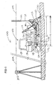
- FIG. 1 illustrates an earthmoving system 100, constructed according to the present invention.
- the system 100 includes a laser transmitter 102 for transmitting a reference beam of laser light 104.
- the beam of laser light is rotated about a vertical axis to define a horizontal reference plane.
- the reference plane may be tilted at a precisely controlled angle to the horizontal if a grade is to be defined by the plane of light.
- the system 100 further includes a bulldozer 106, having a frame 108 and a cutting blade 110.
- the cutting blade 110 is supported by a blade support 112 that extends from the frame 110.
- the blade support 112 includes a pair of hydraulic cylinders 114, only one of which is shown in Fig. 1, for raising and lowering the blade 110 in relation to the frame.
- the blade support 112 further includes a pair of arms 116, one of which is shown in Fig. 1, that are attached to opposite ends of blade 110 and pivotally attached to the frame 108 at 118. Cylinders 114 can be extended or retracted to lower or to raise blade 110 as arms 112 pivot about 118. Cylinders 120 extend between the top of blade 110 and arms 116 and may be used to pivot the blade about pivot connection 122.
- Bulldozer 106 has a cab 124 from which an operator may manually operate various controls to control the operation of the bulldozer.
- the earthmoving system 100 further includes a laser receiver 126 mounted on the bulldozer 106 for sensing the rotating laser light reference beam 104.
- the receiver 126 is shown mounted on a mast 128, which extends upward from the blade 110.
- the receiver 126 detects the height of the beam 104, making it possible to determine the vertical height of the cutting edge 130 of cutting blade 110.
- the difficulty with relying only upon the laser receiver 126 for this information is that it is updated at a relatively slow rate.
- the transmitter 102 typically projects a beam of laser light that is rotated in a reference plane at frequency of perhaps 600 rpm. As a consequence, if the control system of the bulldozer 106 were to rely solely on the laser receiver 126 for a determination of the height of the blade 110, these measurements could only be made at the rate of 10 measurements per second.
- the frame 108 will typically be subjected to impact and vibrations though the cutting blade 110 and tracks 132 and changes in vertical position.
- the frame 108 may pitch forward and aft, in effect rotating about a generally horizontal axis, perpendicular to the direction of travel that extends through the center of gravity 134 of the bulldozer 106. This will, in turn, result in angular movement of the frame 108 and the balance of the bulldozer 106, including the blade 110, by an angle ⁇ .
- vertical movement of the cutting blade 110 may also result from actuation of the cylinders 114 causing the arms 116 to pivot about the rear pivot point 118 with respect to frame 108, by an angle ⁇ .
- ⁇ Elevation Sin ⁇ ⁇ length A + Sin ⁇ ⁇ length B , where A and B are the lengths shown in Fig. 1. Note that if there is no relative movement between the arms 116 and the frame 108, the change in elevation will be a function of only ⁇ . Length A is the distance from the center of gravity 134 to the cutting edge 130, and length B is the distance from the pivot 118 to the cutting edge 130.
- the present invention monitors ⁇ and ⁇ at a higher frequency and overcomes these difficulties. It should be appreciated, however, that monitoring and correcting for only ⁇ changes might be sufficient if the arms 116 are firmly held in position with respect to the frame 108, such that is there is no play in the support, and further if the speed of actuation of the cylinders 114 is limited to provide for slow movement and slow ⁇ changes.
- a gyroscopic position sensor 136 mounted on the frame 108 senses the rotation of the frame 108 about an axis generally transverse to the bulldozer and passing through the center of gravity 134 of the bulldozer.
- the gyroscopic position sensor can be any one of a number of commercially available sensors.
- an angle encoder 138 may be provided on one of the arms 116, adjacent the pivot 118.
- the angle encoder can be any one of a number of commercially available encoders.
- changes in ⁇ may be monitored by other sensors, such as a gyroscopic position sensor, or a sensor that detects the extension length of cylinder 114.
- a control 140 typically located in cab 124, is responsive to the laser receiver 125 and to the gyroscopic orientation sensor 136, for controlling the operation of the cylinders 114 and thereby controlling the position of the cutting blade 110.
- the control 140 is also responsive to the angle encoder 138 for an indication of ⁇ .
- the control 140 determines the position of the cutting blade 110 based upon the output of the gyroscopic position sensor 136, and the control 140 periodically updates the measured position of the cutting blade 110 based upon illumination of the laser receiver 126 by the laser transmitter 102.
- the angle sensor 138 senses the relative position between the blade support 112 and the frame 108.
- the control 140 determines the position of the cutting blade 110 based upon the output of the gyroscopic position sensor 136 and the output of the angle sensor 138.
- the control 140 preferably makes such a determination a plurality of times between successive determinations of the position of the cutting blade 110 based upon the output of the laser receiver 126.
- any earthmoving machine using a blade or other grading implement to cut and fill soil can advantageously employ the present invention, as will be readily apparent to those skilled in the art from the present disclosure.
- a motorgrader, a front end loader, skid steer, or a power shovel may utilize a control according to the present invention, although such a control may be of lesser importance, depending upon the stability or instability of the machine frame, and the speed of operation of the machine.
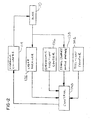
- FIG. 2 illustrates the operation of the present invention.
- the method of operation relates to a method of determining the position of the cutting blade of a bulldozer having a frame and a cutting blade 110.
- the cutting blade 110 is supported by a blade support extending from the frame.
- the blade support includes a pair of hydraulic cylinders 114 for raising and lowering the blade 110 in relation to the frame.
- a position sensor 202 such as for example a GPS system, senses the x and y coordinates of the earthmoving apparatus on the work site, as the earthmoving apparatus moves about the worksite.
- the control 140 receives x and y coordinate position information for the earthmoving apparatus from the position sensor 202. The position of the earthmoving system may then be visually displayed for the operator on a display in cab 124.
- Control 140 also receives signals from the gyroscopic position sensor 136 and laser receiver 126. Periodically the system determines the vertical location of the cutting blade by sensing the relative position of a reference beam of laser light 104 using the laser receiver 126 or other vertical reference system, such as GPS.
- Rotation of the frame 108 about an axis that is generally transverse to the bulldozer and that passes through the center of gravity of the bulldozer is sensed using gyroscopic position sensor 136.
- the operation of the cylinders 114 and the position of the cutting blade 110 are controlled based upon the output of the gyroscopic position sensor 136 and upon the periodically updated position of the cutting blade that is determined by measurement with respect to the beam 104 each time the laser receiver 126 is illuminated.
- the method further includes the steps of sensing the relative position, angle ⁇ , between the blade support 112 and the frame 108 using an angle sensor, and determining the position of the cutting blade based upon the output of the gyroscopic position sensor and the output of the angle sensor. It will be appreciated that the output of the receiver 126 is limited to a prescribed number of measurements per unit time, and that this number coincides with the rotational rate of the transmitter 102, the GPS epoch period or the solution determination and communication rate of an optical robotic station.
Abstract
Description
- The present invention relates to an earthmoving system of the type that incorporates a bulldozer for grading or leveling a tract of land to a desired finish contour and, more particularly to an earthmoving system in which the control system for the earthmoving apparatus is continually updated during the grading process as to the position of the cutting blade of the bulldozer.
- Various control arrangements have been developed to control earthmoving devices, such as bulldozers, so that a tract of land can be graded to a desired height or contour. A number of systems have been developed in which the position of the earthmoving apparatus is determined with a laser, GPS or optically referenced positioning system. In such systems, a tract of land is surveyed and a site plan is drawn up with the desired finish contour. From the tract survey and the site plan, a cut-fill map is produced showing amounts of cut or fill needed in specific areas of the tract of land to produce the desired finish contour. The information is then stored in the computer control system on the earthmoving apparatus.
- The earthmoving apparatus has a position reference receiver, such as a laser receiver, which is coupled to the grading implement or cutting blade. The laser receiver may intercept a reference beam of laser light that is projected from a transmitter and that rotates in a plane above the tract of land. The beam provides vertical position information to the machine control system. The x and y position information may be determined by other reference beams, by a GPS system, or by other navigation techniques. The vertical intercept point of the laser beam on the laser receiver, which is indicative of elevation of the grading implement, is provided to the computer control system, which calculates elevation error of the grading implement based on the cut-fill map and the detected planar position of the apparatus. The elevation error may be displayed for the operator of the earthmoving apparatus who can then make the appropriate adjustments manually. Alternatively, the computer may automatically adjust the elevation of the grading implement to reduce elevation error.
- One limitation encountered with such systems is that the beam of laser light defining the reference plane rotates at a relatively slow rate, e.g. on the order of 10 rotations per second. As a consequence, the computer control system is only able to determine the position of the machine and, most importantly, the vertical position of the cutting blade relatively slowly; typically about once each 1/10th second. This is less frequent than might otherwise be preferred. It has been found that bulldozers, especially, are subject to errors that result from rocking fore and aft as they travel over the rough terrain of a job site that is still in the process of being contoured. Generally, this rocking occurs about an axis that extends laterally with respect to the bulldozer and through the center of gravity of the bulldozer. Monitoring the movement of the bulldozer between laser beam strikes on the receiver permits the position of the cutting blade to be controlled with greater precision and allows for better finishing of the construction site. A second limitation occurs when periodic updates of position from the reference are blocked or missed by the receiver. The proposed solution allows the control system to work for a limited period of time without the reference.
- It is seen that there is a need, therefore, for an earthmoving system and method having a bulldozer or other machine and including a control in which compensation is made for inaccuracies in cutting blade position that would otherwise result from the rotation of the frame of the bulldozer about an axis that is perpendicular to the longitudinal axis of the bulldozer and that passes through the center of gravity of the bulldozer; and for such an earthmoving system and method in which compensation may be provided at a rate which exceeds the rotation or update rate of the laser transmitter that the system uses to determine cutting blade position.
- These needs are met by an earthmoving system according to a first aspect of the present invention, which includes a laser transmitter for transmitting a reference beam of laser light, and a bulldozer having a laser receiver mounted thereon for sensing the laser light. The earthmoving system further comprises a frame and a cutting blade supported by a blade support, extending from the frame. The blade support includes a pair of hydraulic cylinders for raising and lowering the blade in relation to the frame. A gyroscopic position sensor senses rotation of the frame about an axis generally transverse to the earthmoving machine and passing through the center of gravity of the machine. A control is responsive to the laser receiver and to the gyroscopic orientation sensor, and controls the operation of the cylinders and the position of the cutting blade.
- The laser transmitter projects a rotating beam of laser light, and the control determines the position of the cutting blade based upon the output of the gyroscopic position sensor. The control periodically updates the actual position of the cutting blade based upon illumination of the laser receiver by the laser transmitter, allowing correction of any gyroscope-based sensor error that may have accumulated since the previous position sensor input.
- The earthmoving system further comprises an angle sensor sensing the relative position between the blade support and the frame. Alternatively, a means of measuring cylinder displacement can be used in conjunction with known machine geometry to determine the equivalent relative angle between the blade arm and the frame. The control is responsive to the angle sensor and determines the position of the cutting blade based upon the output of the angle sensor and the output of the gyroscopic position sensor more often than the control determines the position of the cutting blade based upon the output of the laser receiver. The control determines the position of the cutting blade each time the receiver is illuminated by the rotating beam. The earthmoving system may also include a reference position system, such as a GPS system, for determining the position of the bulldozer. The bulldozer has a frame and a cutting blade supported by a blade support extending from said frame. The blade support includes a pair of hydraulic cylinders for raising and lowering said blade in relation to the frame. A gyroscopic position sensor senses rotation of the frame about an axis generally transverse to the bulldozer and passing through the center of gravity of said bulldozer. A control is responsive to the reference position system and to the gyroscopic orientation sensor, for controlling the operation of said cylinders and thereby the position of said cutting blade.
- A method, according to a second aspect of the present invention, for determining the position of the cutting blade of a bulldozer meets these needs, as well. The method utilizes a bulldozer or other machine having a frame and the cutting blade. The cutting blade is supported by a blade support extending from the frame. The blade support includes a pair of hydraulic cylinders for raising and lowering the blade in relation to the frame. The location of the cutting blade is periodically determined by sensing the relative position of a reference beam of laser light using a laser receiver mounted on the bulldozer.
- The rotation of the frame about an axis that is generally transverse to the machine and that passes through the center of gravity of the machine is sensed using a gyroscopic position sensor. The operation of the cylinders and the resulting position of the cutting blade are controlled, based upon the outputs from the gyroscopic position sensor. The actual position of the cutting blade is periodically updated based upon illumination of the laser receiver by the laser transmitter. The relative position between the blade support and the frame may be sensed using an angle sensor or alternative means, and the position of the cutting blade determined based upon the output of the gyroscopic position sensor and the output of the angle sensor. This determination may be made a plurality of times between each successive determination of the position of the cutting blade based upon the output of the laser receiver. The method may further include the steps of rotating a beam of laser light, sensing the rotating beam of laser light, and determining the position of the cutting blade.
- According to a third aspect of the present invention, there is provided an earthmoving system, comprising: an earthmoving machine, having a frame and a cutting blade supported by a blade support extending from said frame, said blade support including a pair of hydraulic cylinders for raising and lowering said blade in relation to said frame, an angle sensor sensing the relative position between said blade support and said frame, a gyroscopic position sensor for sensing rotation of said frame about an axis generally transverse to said machine and passing through the center of gravity of said machine, and a control, responsive to said angle sensor and to said gyroscopic position sensor, for detecting the change in position of the cutting blade and controlling the operation of said cylinders, thereby controlling the position of said cutting blade.
- The earthmoving system may further comprise a laser transmitter positioned at a known location and a laser receiver mounted on said machine. The control may periodically update the actual position of said cutting blade based upon illumination of said laser receiver by said laser transmitter.
- The control may determine the position of said cutting blade based upon the output of said gyroscopic position sensor and the output of said angle sensor. The control may make such determination a plurality of times between successive determinations of the position of said cutting blade based upon the output of said laser receiver.
- The control may determine the position of said cutting blade each time said receiver is illuminated by said rotating beam. The control may determine the position of said cutting blade based upon the output of said gyroscopic position sensor.
- According to a fourth aspect of the present invention, there is provided an earthmoving system, comprising: a bulldozer, having a frame and a cutting blade supported by a blade support extending from said frame, said blade support including a pair of hydraulic cylinders for raising and lowering said blade in relation to said frame, a reference position system for determining the position of the bulldozer, a gyroscopic position sensor for sensing rotation of said frame about an axis generally transverse to said bulldozer and passing through the center of gravity of said bulldozer, and a control, responsive to said reference position system and to said gyroscopic orientation sensor, for controlling the operation of said cylinders and thereby the position of said cutting blade.
- The control may determine the position of said cutting blade based upon the output of said gyroscopic position sensor. The control may periodically update the actual position of said cutting blade based upon the output from said reference position system.
- The earthmoving system may comprise an angle sensor sensing the relative position between said blade support and said frame, in which said control is further responsive to said angle sensor and determines the position of said cutting blade based upon the output of said gyroscopic position sensor and the output of said angle sensor, said control making such determination a plurality of times between successive determinations of the position of said cutting blade based upon the output of said reference position system. The control may be further responsive to said angle sensor and may determine the position of said cutting blade based upon the output of said gyroscopic position sensor and the output of said angle sensor.
- According to a fifth aspect of the present invention, there is provided a method of determining the position of the cutting blade of a bulldozer, said bulldozer having a frame and said cutting blade, said cutting blade supported by a blade support extending from said frame, said blade support including a pair of hydraulic cylinders for raising and lowering said blade in relation to said frame, comprising the steps of: sensing rotation of said frame about an axis that is generally transverse to said bulldozer and that passes through the center of gravity of said bulldozer using a gyroscopic position sensor, and controlling the operation of said cylinders and thereby the position of said cutting blade based upon the output of said gyroscopic position sensor, and periodically updating the actual position of said cutting blade.
- The method may further comprise the steps of: sensing the relative position between said blade support and said frame using an angle sensor, and determining the position of said cutting blade based upon the output of said gyroscopic position sensor and the output of said angle sensor a plurality of times between each successive determination of the position of said cutting blade by other means.
- The method may further comprise the steps of: rotating a beam of laser light, sensing the rotating beam of laser light, and determining the position of the cutting blade. The method may also comprise determining the position of said cutting blade each time said receiver is illuminated by said rotating beam.
- It is an object of the present invention to provide an earthmoving system and a method of operation an earthmoving system in which the location of cutting blade is determined, at least in part, by using the output of a gyroscopic position sensor, or by measuring the relative angle between the blade and the frame. Other objects and advantages of the invention will be apparent from the following description, the accompanying drawings, and the appended claims.
-
- FIG. 1 is a side elevation view of an earthmoving system in accordance with the present invention; and
- FIG. 2 is a block diagram of the control used in the earthmoving system of FIG. 1, in accordance with the present invention.
- Reference is now made to FIG. 1, which illustrates an earthmoving system 100, constructed according to the present invention. The system 100 includes a
laser transmitter 102 for transmitting a reference beam oflaser light 104. The beam of laser light is rotated about a vertical axis to define a horizontal reference plane. As is known, the reference plane may be tilted at a precisely controlled angle to the horizontal if a grade is to be defined by the plane of light. - The system 100 further includes a
bulldozer 106, having aframe 108 and acutting blade 110. Thecutting blade 110 is supported by a blade support 112 that extends from theframe 110. The blade support 112 includes a pair ofhydraulic cylinders 114, only one of which is shown in Fig. 1, for raising and lowering theblade 110 in relation to the frame. The blade support 112 further includes a pair of arms 116, one of which is shown in Fig. 1, that are attached to opposite ends ofblade 110 and pivotally attached to theframe 108 at 118.Cylinders 114 can be extended or retracted to lower or to raiseblade 110 as arms 112 pivot about 118. Cylinders 120 extend between the top ofblade 110 and arms 116 and may be used to pivot the blade aboutpivot connection 122.Bulldozer 106 has acab 124 from which an operator may manually operate various controls to control the operation of the bulldozer. - The earthmoving system 100 further includes a
laser receiver 126 mounted on thebulldozer 106 for sensing the rotating laserlight reference beam 104. Thereceiver 126 is shown mounted on amast 128, which extends upward from theblade 110. Thereceiver 126 detects the height of thebeam 104, making it possible to determine the vertical height of thecutting edge 130 of cuttingblade 110. The difficulty with relying only upon thelaser receiver 126 for this information is that it is updated at a relatively slow rate. Thetransmitter 102 typically projects a beam of laser light that is rotated in a reference plane at frequency of perhaps 600 rpm. As a consequence, if the control system of thebulldozer 106 were to rely solely on thelaser receiver 126 for a determination of the height of theblade 110, these measurements could only be made at the rate of 10 measurements per second. - As the
bulldozer 106 moves forward, theframe 108 will typically be subjected to impact and vibrations though thecutting blade 110 andtracks 132 and changes in vertical position. As a consequence, theframe 108 may pitch forward and aft, in effect rotating about a generally horizontal axis, perpendicular to the direction of travel that extends through the center ofgravity 134 of thebulldozer 106. This will, in turn, result in angular movement of theframe 108 and the balance of thebulldozer 106, including theblade 110, by an angle α. Further, vertical movement of thecutting blade 110 may also result from actuation of thecylinders 114 causing the arms 116 to pivot about therear pivot point 118 with respect to frame 108, by an angle β. It will be noted that the resulting change in the elevation of thecutting blade 110 can be estimated as:
where A and B are the lengths shown in Fig. 1. Note that if there is no relative movement between the arms 116 and theframe 108, the change in elevation will be a function of only Δα. Length A is the distance from the center ofgravity 134 to thecutting edge 130, and length B is the distance from thepivot 118 to thecutting edge 130. Whereas attempting to estimate changes in vertical position of the blade from double integration of acceleration data at the blade is very difficult because of the wide variety in frequency and scale of input, it is much simpler to use single integration of the lower rate rotational motion directly measured by a gyroscope. The changes in vertical position measured in this fashion can be monitored at a substantially higher rate than the rotational input motions. These motions however can occur at a rate near the frequency of the reference system updates. As a consequence, monitoring the position of theblade 10 times per second using thereceiver 126 may not provide sufficient opportunity for corrective action, resulting in a lack of precise elevation control. - The present invention monitors Δα and Δβ at a higher frequency and overcomes these difficulties. It should be appreciated, however, that monitoring and correcting for only Δα changes might be sufficient if the arms 116 are firmly held in position with respect to the
frame 108, such that is there is no play in the support, and further if the speed of actuation of thecylinders 114 is limited to provide for slow movement and slow Δβ changes. - To monitor changes in Δα, a
gyroscopic position sensor 136 mounted on theframe 108 senses the rotation of theframe 108 about an axis generally transverse to the bulldozer and passing through the center ofgravity 134 of the bulldozer. The gyroscopic position sensor can be any one of a number of commercially available sensors. To monitor changes in Δβ, anangle encoder 138 may be provided on one of the arms 116, adjacent thepivot 118. The angle encoder can be any one of a number of commercially available encoders. Alternatively, changes in Δβ may be monitored by other sensors, such as a gyroscopic position sensor, or a sensor that detects the extension length ofcylinder 114. - A
control 140, typically located incab 124, is responsive to the laser receiver 125 and to thegyroscopic orientation sensor 136, for controlling the operation of thecylinders 114 and thereby controlling the position of thecutting blade 110. In those systems in which Δβ is also monitored, thecontrol 140 is also responsive to theangle encoder 138 for an indication of Δβ. Thecontrol 140 determines the position of thecutting blade 110 based upon the output of thegyroscopic position sensor 136, and thecontrol 140 periodically updates the measured position of thecutting blade 110 based upon illumination of thelaser receiver 126 by thelaser transmitter 102. Theangle sensor 138 senses the relative position between the blade support 112 and theframe 108. Thecontrol 140 determines the position of thecutting blade 110 based upon the output of thegyroscopic position sensor 136 and the output of theangle sensor 138. Thecontrol 140 preferably makes such a determination a plurality of times between successive determinations of the position of thecutting blade 110 based upon the output of thelaser receiver 126. - Although the earthmoving apparatus 100 is illustrated as a bulldozer, any earthmoving machine using a blade or other grading implement to cut and fill soil can advantageously employ the present invention, as will be readily apparent to those skilled in the art from the present disclosure. For example, a motorgrader, a front end loader, skid steer, or a power shovel may utilize a control according to the present invention, although such a control may be of lesser importance, depending upon the stability or instability of the machine frame, and the speed of operation of the machine.
- FIG. 2 illustrates the operation of the present invention. As will be appreciated, the method of operation relates to a method of determining the position of the cutting blade of a bulldozer having a frame and a
cutting blade 110. Thecutting blade 110 is supported by a blade support extending from the frame. The blade support includes a pair ofhydraulic cylinders 114 for raising and lowering theblade 110 in relation to the frame. Aposition sensor 202, such as for example a GPS system, senses the x and y coordinates of the earthmoving apparatus on the work site, as the earthmoving apparatus moves about the worksite. - The
control 140 receives x and y coordinate position information for the earthmoving apparatus from theposition sensor 202. The position of the earthmoving system may then be visually displayed for the operator on a display incab 124. -
Control 140 also receives signals from thegyroscopic position sensor 136 andlaser receiver 126. Periodically the system determines the vertical location of the cutting blade by sensing the relative position of a reference beam oflaser light 104 using thelaser receiver 126 or other vertical reference system, such as GPS. - Rotation of the
frame 108 about an axis that is generally transverse to the bulldozer and that passes through the center of gravity of the bulldozer is sensed usinggyroscopic position sensor 136. The operation of thecylinders 114 and the position of thecutting blade 110 are controlled based upon the output of thegyroscopic position sensor 136 and upon the periodically updated position of the cutting blade that is determined by measurement with respect to thebeam 104 each time thelaser receiver 126 is illuminated. - The method further includes the steps of sensing the relative position, angle β, between the blade support 112 and the
frame 108 using an angle sensor, and determining the position of the cutting blade based upon the output of the gyroscopic position sensor and the output of the angle sensor. It will be appreciated that the output of thereceiver 126 is limited to a prescribed number of measurements per unit time, and that this number coincides with the rotational rate of thetransmitter 102, the GPS epoch period or the solution determination and communication rate of an optical robotic station. - Having thus described the earthmoving apparatus and method of the present invention in detail and by reference to preferred embodiments thereof, it will be apparent that modifications and variations are possible without departing from the scope of the invention defined in the appended claims.
Claims (10)
- An earthmoving system, comprising:a laser transmitter for transmitting a reference beam of laser light,a bulldozer, having a frame and a cutting blade supported by a blade support extending from said frame, said blade support including a pair of hydraulic cylinders for raising and lowering said blade in relation to said frame,a laser receiver mounted on said bulldozer for sensing said laser light in said reference beam,a gyroscopic position sensor for sensing rotation of said frame about an axis generally transverse to said bulldozer and passing through the center of gravity of said bulldozer, anda control, responsive to said laser receiver and to said gyroscopic orientation sensor, for controlling the operation of said cylinders and thereby the position of said cutting blade.
- The earthmoving system of claim 1, in which said laser transmitter projects a rotating beam of laser light, and in which said control determines the position of said cutting blade based upon the output of said gyroscopic position sensor, and in which said control periodically updates the actual position of said cutting blade based upon illumination of said laser receiver by said laser transmitter.
- The earthmoving system of claim 1 or claim 2, further comprising an angle sensor sensing the relative position between said blade support and said frame, in which said control is further responsive to said angle sensor and determines the position of said cutting blade based upon the output of said gyroscopic position sensor and the output of said angle sensor, said control making such determination a plurality of times between successive determinations of the position of said cutting blade based upon the output of said laser receiver.
- The earthmoving system of claim 1, in which said laser transmitter comprises a transmitter that provides a rotating beam of laser light, and in which said control determines the position of said cutting blade each time said receiver is illuminated by said rotating beam.
- The earthmoving system of claim 4, in which said control determines the position of said cutting blade based upon the output of said gyroscopic position sensor.
- The earthmoving system of claim 4 or claim 5, further comprising an angle sensor sensing the relative position between said blade support and said frame, and in which said control is further responsive to said angle sensor and determines the position of said cutting blade based upon the output of said gyroscopic position sensor and the output of said angle sensor.
- A method of determining the position of the cutting blade of a bulldozer, said bulldozer having a frame and said cutting blade, said cutting blade supported by a blade support extending from said frame, said blade support including a pair of hydraulic cylinders for raising and lowering said blade in relation to said frame, comprising the steps of:periodically determining the location of the cutting blade by sensing the relative position of a reference beam of laser light using a laser receiver mounted on said bulldozer,sensing rotation of said frame about an axis that is generally transverse to said bulldozer and that passes through the center of gravity of said bulldozer using a gyroscopic position sensor, andcontrolling the operation of said cylinders and thereby the position of said cutting blade based upon the output of said gyroscopic position sensor, andperiodically updating the actual position of said cutting blade based upon illumination of said laser receiver by said laser transmitter.
- The method of determining the position of the cutting blade of a bulldozer according to claim 7, further comprising the steps of:sensing the relative position between said blade support and said frame using an angle sensor, anddetermining the position of said cutting blade based upon the output of said gyroscopic position sensor and the output of said angle sensor a plurality of times between each successive determination of the position of said cutting blade based upon the output of said laser receiver.
- The method of determining the position of the cutting blade of a bulldozer according to claim 7 or claim 8, further comprising the steps of:rotating a beam of laser light,sensing the rotating beam of laser light, anddetermining the position of the cutting blade.
- The method of determining the position of the cutting blade of a bulldozer according to claim 9, further comprising the step of determining the position of said cutting blade each time said receiver is illuminated by said rotating beam.
Applications Claiming Priority (1)
| Application Number | Priority Date | Filing Date | Title |
|---|---|---|---|
| US11/581,605 US20080087447A1 (en) | 2006-10-16 | 2006-10-16 | Control and method of control for an earthmoving system |
Publications (2)
| Publication Number | Publication Date |
|---|---|
| EP1914352A2 true EP1914352A2 (en) | 2008-04-23 |
| EP1914352A3 EP1914352A3 (en) | 2009-07-08 |
Family
ID=38925699
Family Applications (1)
| Application Number | Title | Priority Date | Filing Date |
|---|---|---|---|
| EP07253870A Withdrawn EP1914352A3 (en) | 2006-10-16 | 2007-09-28 | Control and method of control for an earthmoving system |
Country Status (2)
| Country | Link |
|---|---|
| US (1) | US20080087447A1 (en) |
| EP (1) | EP1914352A3 (en) |
Cited By (5)
| Publication number | Priority date | Publication date | Assignee | Title |
|---|---|---|---|---|
| FR2996865A1 (en) * | 2012-10-17 | 2014-04-18 | Yves Blandin | DEVICE FOR ELECTRICAL AND ELECTRONIC COMPENSATIONS FOR LEVELING AND COMPACTING |
| WO2018085095A1 (en) * | 2016-11-07 | 2018-05-11 | The Climate Corporation | Work layer imaging and analysis for implement monitoring, control and operator feedback |
| CN108779619A (en) * | 2016-07-26 | 2018-11-09 | 株式会社小松制作所 | Control system, control method and the working truck of working truck |
| FR3085048A1 (en) * | 2018-08-20 | 2020-02-21 | Bridgin | LEVELING GUIDANCE SYSTEM FOR EXCAVATION OR EARTHMOVING MACHINES |
| US10679341B2 (en) | 2015-05-08 | 2020-06-09 | The Climate Corporation | Work layer imaging and analysis for implement monitoring, control and operator feedback |
Families Citing this family (15)
| Publication number | Priority date | Publication date | Assignee | Title |
|---|---|---|---|---|
| US9746329B2 (en) * | 2006-11-08 | 2017-08-29 | Caterpillar Trimble Control Technologies Llc | Systems and methods for augmenting an inertial navigation system |
| US8078297B2 (en) * | 2006-12-01 | 2011-12-13 | Trimble Navigation Limited | Interface for retrofitting a manually controlled machine for automatic control |
| US8090507B2 (en) | 2008-01-23 | 2012-01-03 | Gradient Inc. | Pitch plow and method of controlling an elevation of a cutting edge of a pitch plow |
| WO2011107096A1 (en) * | 2010-03-05 | 2011-09-09 | Mikrofyn A/S | An apparatus and a method for height control for a dozer blade |
| US8634991B2 (en) | 2010-07-01 | 2014-01-21 | Caterpillar Trimble Control Technologies Llc | Grade control for an earthmoving system at higher machine speeds |
| US20130158818A1 (en) * | 2011-12-20 | 2013-06-20 | Caterpillar Inc. | Implement control system for a machine |
| US9551130B2 (en) | 2015-02-05 | 2017-01-24 | Deere & Company | Blade stabilization system and method for a work vehicle |
| US9624643B2 (en) | 2015-02-05 | 2017-04-18 | Deere & Company | Blade tilt system and method for a work vehicle |
| US9328479B1 (en) | 2015-02-05 | 2016-05-03 | Deere & Company | Grade control system and method for a work vehicle |
| US10030366B2 (en) | 2016-04-04 | 2018-07-24 | Caterpillar Inc. | Drawbar position determination with rotational sensors |
| US10287745B1 (en) * | 2016-04-13 | 2019-05-14 | Abi Attachments, Inc. | Work machines including automatic grading features and functions |
| CN107558518B (en) * | 2017-10-21 | 2023-04-07 | 盐城师范学院 | Mud flat soil leveling device capable of automatically adjusting levelness |
| US10533301B1 (en) * | 2018-12-20 | 2020-01-14 | David Armas | GPS and laser grading control |
| US20200256997A1 (en) * | 2019-02-08 | 2020-08-13 | Topcon Positioning Systems, Inc. | System and method for tracking a reference laser |
| CN113056970B (en) * | 2021-03-23 | 2022-07-12 | 惠安豪行优运科技有限公司 | A mechanical type bulldozing equipment for agricultural |
Citations (3)
| Publication number | Priority date | Publication date | Assignee | Title |
|---|---|---|---|---|
| US5964298A (en) * | 1994-06-13 | 1999-10-12 | Giganet, Inc. | Integrated civil engineering and earthmoving system |
| US6112145A (en) * | 1999-01-26 | 2000-08-29 | Spectra Precision, Inc. | Method and apparatus for controlling the spatial orientation of the blade on an earthmoving machine |
| US20050197756A1 (en) * | 1998-11-27 | 2005-09-08 | Taylor Arthur J. | Method and system for performing non-contact based determination of the position of an implement |
Family Cites Families (15)
| Publication number | Priority date | Publication date | Assignee | Title |
|---|---|---|---|---|
| US2904911A (en) * | 1955-04-04 | 1959-09-22 | Preco Inc | Gyroscopic control mechanism for grading apparatus |
| US2965990A (en) * | 1956-07-13 | 1960-12-27 | Preco Inc | Automatic control mechanism for grading apparatus |
| US3046681A (en) * | 1960-05-23 | 1962-07-31 | Honeywell Regulator Co | Control apparatus |
| US3786871A (en) * | 1971-07-26 | 1974-01-22 | Grad Line | Grader control |
| JPS5139447B2 (en) * | 1971-09-06 | 1976-10-28 | ||
| US4162708A (en) * | 1975-02-03 | 1979-07-31 | Dakota Electron, Inc. | Tool carrying vehicle with laser control apparatus |
| JPS5330102A (en) * | 1976-08-31 | 1978-03-22 | Komatsu Mfg Co Ltd | Device for automatically controlling blade of bulldozer |
| AU628860B2 (en) * | 1989-09-14 | 1992-09-24 | Kabushiki Kaisha Komatsu Seisakusho | Blade controller of bulldozer |
| US5375663A (en) * | 1993-04-01 | 1994-12-27 | Spectra-Physics Laserplane, Inc. | Earthmoving apparatus and method for grading land providing continuous resurveying |
| US5551518A (en) * | 1994-09-28 | 1996-09-03 | Caterpillar Inc. | Tilt rate compensation implement system and method |
| US5862501A (en) * | 1995-08-18 | 1999-01-19 | Trimble Navigation Limited | Guidance control system for movable machinery |
| US6168348B1 (en) * | 1998-01-16 | 2001-01-02 | Southern Laser, Inc. | Bi-directional surface leveling system |
| US6152238A (en) * | 1998-09-23 | 2000-11-28 | Laser Alignment, Inc. | Control and method for positioning a tool of a construction apparatus |
| US7246456B2 (en) * | 2004-02-18 | 2007-07-24 | Caterpillar Trimble Control Technologies Llc | Linked mode for a multi-axis machine control |
| US7168174B2 (en) * | 2005-03-14 | 2007-01-30 | Trimble Navigation Limited | Method and apparatus for machine element control |
-
2006
- 2006-10-16 US US11/581,605 patent/US20080087447A1/en not_active Abandoned
-
2007
- 2007-09-28 EP EP07253870A patent/EP1914352A3/en not_active Withdrawn
Patent Citations (3)
| Publication number | Priority date | Publication date | Assignee | Title |
|---|---|---|---|---|
| US5964298A (en) * | 1994-06-13 | 1999-10-12 | Giganet, Inc. | Integrated civil engineering and earthmoving system |
| US20050197756A1 (en) * | 1998-11-27 | 2005-09-08 | Taylor Arthur J. | Method and system for performing non-contact based determination of the position of an implement |
| US6112145A (en) * | 1999-01-26 | 2000-08-29 | Spectra Precision, Inc. | Method and apparatus for controlling the spatial orientation of the blade on an earthmoving machine |
Cited By (12)
| Publication number | Priority date | Publication date | Assignee | Title |
|---|---|---|---|---|
| FR2996865A1 (en) * | 2012-10-17 | 2014-04-18 | Yves Blandin | DEVICE FOR ELECTRICAL AND ELECTRONIC COMPENSATIONS FOR LEVELING AND COMPACTING |
| EP2722445A1 (en) | 2012-10-17 | 2014-04-23 | Yves Blandin | Electric and electronic compensation device for multifunctional levelling and compacting tool |
| US10679341B2 (en) | 2015-05-08 | 2020-06-09 | The Climate Corporation | Work layer imaging and analysis for implement monitoring, control and operator feedback |
| US11170497B2 (en) | 2015-05-08 | 2021-11-09 | The Climate Corporation | Work layer imaging and analysis for implement monitoring, control and operator feedback |
| US11615525B2 (en) | 2015-05-08 | 2023-03-28 | Climate Llc | Work layer imaging and analysis for implement monitoring, control and operator feedback |
| CN108779619A (en) * | 2016-07-26 | 2018-11-09 | 株式会社小松制作所 | Control system, control method and the working truck of working truck |
| CN108779619B (en) * | 2016-07-26 | 2021-05-07 | 株式会社小松制作所 | Work vehicle control system, work vehicle control method, and work vehicle |
| US11001993B2 (en) | 2016-07-26 | 2021-05-11 | Komatsu Ltd. | Control system for work vehicle, control method, and work vehicle |
| WO2018085095A1 (en) * | 2016-11-07 | 2018-05-11 | The Climate Corporation | Work layer imaging and analysis for implement monitoring, control and operator feedback |
| US10768331B2 (en) | 2016-11-07 | 2020-09-08 | The Climate Corporation | Work layer imaging and analysis for implement monitoring, control and operator feedback |
| FR3085048A1 (en) * | 2018-08-20 | 2020-02-21 | Bridgin | LEVELING GUIDANCE SYSTEM FOR EXCAVATION OR EARTHMOVING MACHINES |
| EP3613905A1 (en) * | 2018-08-20 | 2020-02-26 | Bridgin | Levelling guiding system for excavating or earthmoving plant |
Also Published As
| Publication number | Publication date |
|---|---|
| US20080087447A1 (en) | 2008-04-17 |
| EP1914352A3 (en) | 2009-07-08 |
Similar Documents
| Publication | Publication Date | Title |
|---|---|---|
| EP1914352A2 (en) | Control and method of control for an earthmoving system | |
| EP3194666B1 (en) | Guidance system for earthmoving machinery | |
| KR101516693B1 (en) | Excavation control system for hydraulic shovel | |
| US7970519B2 (en) | Control for an earth moving system while performing turns | |
| EP2432943B1 (en) | Semiautomatic control of earthmoving machine based on attitude measurement | |
| US8634991B2 (en) | Grade control for an earthmoving system at higher machine speeds | |
| AU719511B2 (en) | Apparatus and method for determining the position of a work implement | |
| JP5873607B1 (en) | Work machine calibration apparatus and work machine parameter calibration method | |
| US6691437B1 (en) | Laser reference system for excavating machine | |
| EP2912232B1 (en) | Wheel loader comprising a grading blade and a machine control system | |
| US9746329B2 (en) | Systems and methods for augmenting an inertial navigation system | |
| US8091256B2 (en) | Loader elevation control system | |
| EP2542726B1 (en) | An apparatus and a method for height control for a dozer blade | |
| CN111380522A (en) | Navigation positioning and automatic cutting method of cantilever type tunneling machine | |
| CN111441406B (en) | Bird's eye view calibration for slope control | |
| JPS63130832A (en) | Automatic ground grading method of high accuracy | |
| JP2021001435A (en) | Work machine and control method thereof |
Legal Events
| Date | Code | Title | Description |
|---|---|---|---|
| PUAI | Public reference made under article 153(3) epc to a published international application that has entered the european phase |
Free format text: ORIGINAL CODE: 0009012 |
|
| AK | Designated contracting states |
Kind code of ref document: A2 Designated state(s): AT BE BG CH CY CZ DE DK EE ES FI FR GB GR HU IE IS IT LI LT LU LV MC MT NL PL PT RO SE SI SK TR |
|
| AX | Request for extension of the european patent |
Extension state: AL BA HR MK RS |
|
| PUAL | Search report despatched |
Free format text: ORIGINAL CODE: 0009013 |
|
| AK | Designated contracting states |
Kind code of ref document: A3 Designated state(s): AT BE BG CH CY CZ DE DK EE ES FI FR GB GR HU IE IS IT LI LT LU LV MC MT NL PL PT RO SE SI SK TR |
|
| AX | Request for extension of the european patent |
Extension state: AL BA HR MK RS |
|
| 17P | Request for examination filed |
Effective date: 20100108 |
|
| AKX | Designation fees paid |
Designated state(s): AT BE BG CH CY CZ DE DK EE ES FI FR GB GR HU IE IS IT LI LT LU LV MC MT NL PL PT RO SE SI SK TR |
|
| 17Q | First examination report despatched |
Effective date: 20110107 |
|
| STAA | Information on the status of an ep patent application or granted ep patent |
Free format text: STATUS: THE APPLICATION IS DEEMED TO BE WITHDRAWN |
|
| 18D | Application deemed to be withdrawn |
Effective date: 20110518 |