EP1911623A2 - Vehicular multifunction control system - Google Patents
Vehicular multifunction control system Download PDFInfo
- Publication number
- EP1911623A2 EP1911623A2 EP07019159A EP07019159A EP1911623A2 EP 1911623 A2 EP1911623 A2 EP 1911623A2 EP 07019159 A EP07019159 A EP 07019159A EP 07019159 A EP07019159 A EP 07019159A EP 1911623 A2 EP1911623 A2 EP 1911623A2
- Authority
- EP
- European Patent Office
- Prior art keywords
- input device
- characteristic adjustment
- vehicle
- characteristic
- control system
- Prior art date
- Legal status (The legal status is an assumption and is not a legal conclusion. Google has not performed a legal analysis and makes no representation as to the accuracy of the status listed.)
- Withdrawn
Links
- 230000004044 response Effects 0.000 claims description 5
- 230000008859 change Effects 0.000 abstract description 7
- 230000000994 depressogenic effect Effects 0.000 description 2
- 238000013507 mapping Methods 0.000 description 2
- 230000000007 visual effect Effects 0.000 description 2
- 230000009471 action Effects 0.000 description 1
- 238000004378 air conditioning Methods 0.000 description 1
- 230000004323 axial length Effects 0.000 description 1
- 230000000881 depressing effect Effects 0.000 description 1
- 238000010438 heat treatment Methods 0.000 description 1
- 230000001953 sensory effect Effects 0.000 description 1
- 238000010257 thawing Methods 0.000 description 1
- 238000009423 ventilation Methods 0.000 description 1
Images
Classifications
-
- B60K35/10—
-
- B60K2360/122—
-
- B60K2360/143—
Definitions
- the present invention pertains generally to vehicular multifunction control systems.
- a motor vehicle typically includes a multitude of components and systems that enhance the comfort and convenience of the driver and passengers.
- Such systems include, for example, audio systems having a radio, speakers, compact disc player, and cassette player; climate systems having heating, ventilation, and air conditioning components; navigational systems; etc.
- Each of the systems typically includes an interface through which the driver of the vehicle can interact with the system.
- control of a system requires that the driver of the vehicle input command information via the interface to which the system is responsive to vary a system characteristic.
- Each system may also supply information to the driver via the interface. For example, an audio system will indicate the radio station to which it is tuned, a climate control system will indicate the fan speed or the thermostat setting, and a navigational system will indicate location information.
- Each system typically includes its own dedicated interface.
- a climate control system includes a plurality of switches, buttons, dials, etc. that are operable to control only the climate control system.
- an audio system includes a plurality of switches, buttons, dials, etc. that are operable only to control the audio system.
- a multifunction control system for a vehicle having a plurality of variable characteristics.
- the control system includes two input devices, i.e., a mode selector input device and a characteristic adjustment input device.
- the control system is configured such that manipulation of the mode selector input device causes, at least in part, the control system to alternate between at least two modes of operation, including a first mode and a second mode.
- the characteristic adjustment input device In the first mode of operation, is manipulable by a driver or passenger to alter a first variable characteristic.
- the characteristic adjustment input device is manipulable by the driver or passenger to alter a second variable characteristic.
- the selector input device and/or the characteristic adjustment input device may include switches, touchpad devices, force sensing devices, proximity sensing devices, motion sensing devices, sliders, rockers, knobs or any other known input devices.
- vehicle systems include a climate system having variable characteristics such as air temperature, fan speed, and air flow mode; an audio system having variable characteristics such as radio tuner frequency, speaker volume, compact disc track playing; etc.
- the control system preferably further includes a display defining multiple regions that are configured to visually indicate the status of the plurality of variable characteristics.
- the selector input device and the characteristic adjustment input device are preferably one-to-one mapped with the display such that the regions of the display have a predetermined spatial relationship with one another, and the input devices have substantially the same spatial relationship with one another.
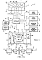
- FIGURE 1 is a schematic depiction of a vehicle with vehicular systems and a control system with a plurality of input devices and a display for controlling the vehicular systems;
- FIGURE 1A is a schematic elevational view of the input devices of Figure 1 in accordance with the preferred embodiment.
- the control system 10 includes a plurality of input devices 14A-E.
- the input devices 14A-E will initially be described as barrel switches 14A-E in accordance with the preferred embodiment, and will thereafter be described as including other known devices in accordance with a plurality of alternate embodiments.
- the barrel switches 14A-E have a common axis of symmetry A.
- Switches 14A-E are generally circular in cross-section in a plane that is perpendicular to axis A.
- the switches 14A-E may have differing radial dimensions to provide a tactile distinguishing feature and thus facilitate a driver's ability to distinguish the switches.
- the central switch 14C is about 50 millimeters in diameter.
- End switches 14A, 14E are about 30 millimeters in diameter.
- Switches 14B, 14D are about 20 millimeters in diameter.
- the switches 14A-E may also have differing axial lengths, with the central switch 14C having a length of about 10 millimeters, end switches 14A, 14E having a length of about 25 millimeters, and switches 14B, 14D having a length of about 20 millimeters. Approximately 5 millimeters separates adjacent switches.
- the switches 14A-E are preferably located on a center console between a driver's seat and a passenger's seat, on an instrument panel, or on a steering wheel.
- the switches 14A-E may also include different surface textures to facilitate a driver's ability to distinguish them. For example, the switches may be coated with different materials, or have different surface features such as ridges, bumps, etc.
- a switch plate 16 defines a surface 18 that is exposed to the passenger compartment of vehicle 12.
- the switch plate 16 defines a plurality of apertures 20A-E.
- Each of switches 14A-E extends through a respective one of the apertures 20A-E such that at least a portion of each switch protrudes from surface 18 so as to be manipulable by a vehicle occupant to cause rotation about axis A.
- Each barrel switch 14A-E is freely and independently rotatable about axis A.
- the switches 14A-E may also be characterized by different haptic feedback characteristics, i.e., variations in resistance to rotation caused by springs, detents, feedback motors, etc.
- each switch 14A-E is also selectively and independently depressible to a depressed position shown in phantom in Figure 1A.
- the scroll wheel sometimes found on a computer mouse is an exemplary cylindrical barrel switch that is rotatable and depressible.
- the vehicle 12 includes an audio system 24, a climate system 28, a navigation system 32, and a driver information system 36.
- the audio system 24 includes a radio, tape player, compact disk player, and speakers.
- the climate system 28 includes an air conditioner for providing cooled air, a heater for providing heated air, and ducts and vents for providing the heated or cooled air to the vehicle passenger compartment (not shown).
- the ducts are configured to selectively provide air to a first set of vents below an instrument panel, to a second set of vents formed inside the instrument panel and positioned to direct air generally rearward, and a third set of vents formed in the instrument panel and positioned to direct air to a windshield for use in defrosting, as understood by those skilled in the art.
- Each of systems 24, 28, 32, 36 has a plurality of selectively variable system characteristics.
- the control system 10 includes a controller 40 operatively connected to the switches 14A-E.
- the switches 14A-E are configured to generate signals 41 when rotated or depressed.
- the signals 41 are transmitted to the controller 40, such as by wires, flexible circuit boards, etc.
- the controller 40 is configured to transmit control signals 42 to the climate control system 28, the audio system 24, the navigation system 32, and the driver information system 36 so that the control system 10 functions as described herein.
- Systems 24, 28, 32, 36 are responsive to signals 42 by varying or altering one or more system or component characteristics.
- the controller 40 is programmed and configured to provide the control system 10 with four modes of operation.
- a first mode of operation each of switches 14A, 14B, 14D, 14E is manipulable to alter a respective variable characteristic of the audio system 24.
- each of switches 14A, 14B, 14D, 14E is manipulable to alter a respective variable characteristic of the climate system 28.
- a third mode of operation each of switches 14A, 14B, 14D, 14E is manipulable to alter a respective variable characteristic of the navigation system 32.
- each of switches 14A, 14B, 14D, 14E is manipulable to alter a respective variable characteristic of the driver information system 36. Switches 14A, 14B, 14D, 14E are thus "characteristic adjustment switches.”
- manipulation of a switch "enables the variation” or “causes the variation” of a variable characteristic if the manipulation, either by itself or in conjunction with another action, causes a change in the variable characteristic.
- rotation of a switch 14A-E enables or causes the variation of a variable characteristic if the control system 10 causes the characteristic to change automatically upon the rotation.
- rotation of a switch 14A-E enables or causes the variation of a variable characteristic if the control system 10 causes the characteristic to change upon the rotation and an additional input by the driver, such as depressing the switch.
- the controller 40 is configured such that rotation of the central switch 14C causes the control system 10 to alternate between the first, second, third, and fourth modes of operation, and thus switch 14C is referred to herein as a "mode selector switch” or a "mode selector input device”.
- the controller 40 is also configured such that rotation of the switches 14A, 14B, 14D and 14E causes the control system 10 to adjust some variable characteristic of the selected mode, and thus the switches 14A, 14B, 14D and 14E are referred to herein as "characteristic adjustment switches” or "characteristic adjustment input devices”.
- the control system 10 also includes a display 44 sufficiently located within the vehicle 12 for viewing by a driver or passenger.
- Exemplary display 44 locations include the vehicle instrument panel, gage cluster, heads-up display, base of windshield, A-pillar, etc.
- the controller 40 is configured to transmit signals 46 to the display 44 to control the display 44 so that the display functions as described herein.
- the display 44 is configured to selectively depict indicia representing the current state of the control system 10 and variable system characteristics. More specifically, the controller 40 is configured to cause the display 44 to depict a plurality of icons. Each icon is a symbol that is representative of a vehicle component or system, or representative of a variable characteristic of a vehicle component or system.
- the icons which may also be referred to herein as "indicia,” may include alphanumeric characters, graphs, lists, etc., within the scope of the claimed invention.
- the display 44 provides information to the driver about the vehicle systems, and provides visual feedback of switch 14A-E manipulation.
- Four icons 48A-D are depicted on the display 44.
- Icon 48A represents the audio system
- icon 48B represents the climate system
- icon 48C represents the navigational system 32
- icon 48D represents the driver information system 36.
- icons 48A-D is responsive to rotation of switch 14C to indicate in which of the four modes the control system 10 is operating, or will be operating upon the occurrence of an additional input by the driver, such as the depression of switch 14C.
- the controller 40 is configured to change the appearance of the icon representing the system that is presently controllable by manipulation of switches 14A, 14B, 14D, 14E.
- the icon representing the system selected for control includes a box 52.
- Those skilled in the art will recognize other means of changing the appearance of an icon that may be employed within the scope of the claimed invention, such as changing the size of the icon, changing the color of the icon, etc.
- icon 48A includes box 52 to indicate that the control system 10 is in the first mode of operation wherein the manipulation of switches 14A-B and 14D-E enables variation in audio system 24 characteristics.
- the display 44 depicts a first set of icons 56A-D, each indicating the present status of a respective audio system characteristic, or what the status will be after an additional input by the driver.
- Icon 56A includes a schematic depiction of a speaker 58 with curvilinear lines 60 adjacent thereto, and represents the speaker volume.
- Icon 56B includes a line 62 and a bar 64 intersecting, and perpendicular to, the line 62; icon 56B represents audial characteristics of the speakers, which, in Figure 1, is the bass level.
- Icon 56C is an alphanumeric representation of the general source from which the audio system 24 is receiving audial content, which, in Figure 1, is the FM (frequency modulation) band.
- Icon 56D is an alphanumeric representation of the specific source from which the audio system 24 is receiving audial content, which, in Figure 1, is the FM frequency to which the radio of the audio system 24 is tuned.
- the icons 56A, 56B, 48A-D, 56C, and 56D are located within specific regions of the display 44. More precisely, the icon 56A is located within a first region 70A of the display 44, the icon 56B is located within a second region 70B of the display 44, the icons 48A-48D are located within a third region 70C of the display 44, the icon 56C is located within a fourth region 70D of the display 44, and the icon 56D is located within a fifth region 70E of the display 44.
- the regions 70A-70E are shown as being generally columnar, however, other region configurations may be envisioned.
- the present invention preferably implements one-to-one mapping.
- one-to-one mapping ties the spatial relationship of the switches 14A-E together with the spatial relationship of the display regions 70A-70E.
- the operation of the left most switch 14A controls information located in the left most display region 70A (i.e., the icon 56A)
- the operation of the middle switch 14C controls information in the middle display region 70C (i.e., the icons 48A-48D)
- the operation of the right most switch 14E controls information in the right most display region 70E (i.e., the icon 56D).
- the switches 14A-E and the display regions 70A-70E have a corresponding alignment such that respective elements are arranged in a similar sequence or pattern.
- a force feedback device 80 may be implemented to tactilely acknowledge the manipulation of a switch 14A-E and/or to indicate the status of the systems 24, 28, 32 and 36.
- the force feedback device 80 is operatively connected to the controller 40 such that the force feedback device 80 generates tactile feedback in response to a command signal 82 from the controller 40.
- a "force feedback device” applies a force or series of forces to physically engage the operator as a means of conveying information or feedback.
- the force feedback device 80 may be incorporated directly into the switches 14A-E or any other vehicle component. Therefore, as an example, if an operator actuates a switch 14A-E to adjust the seat position, a force feedback device 80 disposed in the seat may vibrate to acknowledge the command.
- Auditory feedback may also be implemented to acknowledge the manipulation of a switch 14A-E and/or to indicate the status of the systems 24, 28, 32 and 36. Therefore, a speaker 84 may be operatively connected to the controller 40 such that the speaker 84 generates auditory feedback in response to a command signal 86 from the controller 40.
- the speaker 84 may be incorporated into the display 44 or into any other vehicle component.
- Some examples of auditory feedback from the speaker 84 may include, for example, any type of sound, speech, or directional sound cues to indicate a specific region of the vehicle 12 being controlled.
- the input devices 14A-E previously described as being barrel switches may include other types of devices.
- the input devices 14A-E may include devices configured to change data without moving such as a touchpad, a force sensor, a proximity sensor, or a motion sensor adapted to identify different types of finger gestures.
- the input devices 14A-E may include sliders, rockers, toggles, joysticks, knobs, or any other known input devices.
- the input devices 14A-E in accordance with the alternate embodiments are each preferably dimensioned to provide a tactile distinguishing feature and thus facilitate a driver's ability to distinguish the input devices 14A-E from each other.
- the orientation or location of the input devices 14A-E may be adjustable such as an apparatus which is removable from its primary position to function as a remote control.
Abstract
Description
- The present invention pertains generally to vehicular multifunction control systems.
- A motor vehicle typically includes a multitude of components and systems that enhance the comfort and convenience of the driver and passengers. Such systems include, for example, audio systems having a radio, speakers, compact disc player, and cassette player; climate systems having heating, ventilation, and air conditioning components; navigational systems; etc.
- Each of the systems typically includes an interface through which the driver of the vehicle can interact with the system. For example, control of a system requires that the driver of the vehicle input command information via the interface to which the system is responsive to vary a system characteristic. Each system may also supply information to the driver via the interface. For example, an audio system will indicate the radio station to which it is tuned, a climate control system will indicate the fan speed or the thermostat setting, and a navigational system will indicate location information.
- Each system typically includes its own dedicated interface. Thus, for example, a climate control system includes a plurality of switches, buttons, dials, etc. that are operable to control only the climate control system. Similarly, an audio system includes a plurality of switches, buttons, dials, etc. that are operable only to control the audio system.
- A multifunction control system is provided for a vehicle having a plurality of variable characteristics. The control system includes two input devices, i.e., a mode selector input device and a characteristic adjustment input device. The control system is configured such that manipulation of the mode selector input device causes, at least in part, the control system to alternate between at least two modes of operation, including a first mode and a second mode. In the first mode of operation, the characteristic adjustment input device is manipulable by a driver or passenger to alter a first variable characteristic. In the second mode, the characteristic adjustment input device is manipulable by the driver or passenger to alter a second variable characteristic.
- In accordance with various embodiments, the selector input device and/or the characteristic adjustment input device may include switches, touchpad devices, force sensing devices, proximity sensing devices, motion sensing devices, sliders, rockers, knobs or any other known input devices.
- Examples of vehicle systems include a climate system having variable characteristics such as air temperature, fan speed, and air flow mode; an audio system having variable characteristics such as radio tuner frequency, speaker volume, compact disc track playing; etc.
- The control system preferably further includes a display defining multiple regions that are configured to visually indicate the status of the plurality of variable characteristics. The selector input device and the characteristic adjustment input device are preferably one-to-one mapped with the display such that the regions of the display have a predetermined spatial relationship with one another, and the input devices have substantially the same spatial relationship with one another.
- The above features and advantages and other features and advantages of the present invention are readily apparent from the following detailed description of the best modes for carrying out the invention when taken in connection with the accompanying drawings.
- FIGURE 1 is a schematic depiction of a vehicle with vehicular systems and a control system with a plurality of input devices and a display for controlling the vehicular systems; and
- FIGURE 1A is a schematic elevational view of the input devices of Figure 1 in accordance with the preferred embodiment.
- Referring to Figure 1, a
multifunction control system 10 for avehicle 12 is schematically depicted. Thecontrol system 10 includes a plurality ofinput devices 14A-E. Theinput devices 14A-E will initially be described asbarrel switches 14A-E in accordance with the preferred embodiment, and will thereafter be described as including other known devices in accordance with a plurality of alternate embodiments. - According to the preferred embodiment, the
barrel switches 14A-E have a common axis ofsymmetry A. Switches 14A-E are generally circular in cross-section in a plane that is perpendicular to axis A. Theswitches 14A-E may have differing radial dimensions to provide a tactile distinguishing feature and thus facilitate a driver's ability to distinguish the switches. In an exemplary embodiment, thecentral switch 14C is about 50 millimeters in diameter.End switches Switches 14B, 14D are about 20 millimeters in diameter. - Similarly, the
switches 14A-E may also have differing axial lengths, with thecentral switch 14C having a length of about 10 millimeters,end switches switches 14A-E are preferably located on a center console between a driver's seat and a passenger's seat, on an instrument panel, or on a steering wheel. Theswitches 14A-E may also include different surface textures to facilitate a driver's ability to distinguish them. For example, the switches may be coated with different materials, or have different surface features such as ridges, bumps, etc. - Referring to Figures 1 and 1A, a
switch plate 16 defines asurface 18 that is exposed to the passenger compartment ofvehicle 12. Theswitch plate 16 defines a plurality ofapertures 20A-E. Each ofswitches 14A-E extends through a respective one of theapertures 20A-E such that at least a portion of each switch protrudes fromsurface 18 so as to be manipulable by a vehicle occupant to cause rotation about axis A. Eachbarrel switch 14A-E is freely and independently rotatable about axis A. Theswitches 14A-E may also be characterized by different haptic feedback characteristics, i.e., variations in resistance to rotation caused by springs, detents, feedback motors, etc. In a preferred embodiment, eachswitch 14A-E is also selectively and independently depressible to a depressed position shown in phantom in Figure 1A. The scroll wheel sometimes found on a computer mouse is an exemplary cylindrical barrel switch that is rotatable and depressible. - Referring specifically to Figure 1, the
vehicle 12 includes anaudio system 24, aclimate system 28, anavigation system 32, and adriver information system 36. In an exemplary embodiment, theaudio system 24 includes a radio, tape player, compact disk player, and speakers. In an exemplary embodiment, theclimate system 28 includes an air conditioner for providing cooled air, a heater for providing heated air, and ducts and vents for providing the heated or cooled air to the vehicle passenger compartment (not shown). The ducts are configured to selectively provide air to a first set of vents below an instrument panel, to a second set of vents formed inside the instrument panel and positioned to direct air generally rearward, and a third set of vents formed in the instrument panel and positioned to direct air to a windshield for use in defrosting, as understood by those skilled in the art. Each ofsystems - The
control system 10 includes acontroller 40 operatively connected to theswitches 14A-E. Theswitches 14A-E are configured to generatesignals 41 when rotated or depressed. Thesignals 41 are transmitted to thecontroller 40, such as by wires, flexible circuit boards, etc. Thecontroller 40 is configured to transmitcontrol signals 42 to theclimate control system 28, theaudio system 24, thenavigation system 32, and thedriver information system 36 so that thecontrol system 10 functions as described herein.Systems - The
controller 40 is programmed and configured to provide thecontrol system 10 with four modes of operation. In a first mode of operation, each ofswitches audio system 24. In a second mode of operation, each ofswitches climate system 28. In a third mode of operation, each ofswitches navigation system 32. In a fourth mode of operation, each ofswitches driver information system 36.Switches - In the context of the present invention, manipulation of a switch "enables the variation" or "causes the variation" of a variable characteristic if the manipulation, either by itself or in conjunction with another action, causes a change in the variable characteristic. Thus, for example, and within the scope of the claimed invention, rotation of a
switch 14A-E enables or causes the variation of a variable characteristic if thecontrol system 10 causes the characteristic to change automatically upon the rotation. Similarly, and within the scope of the claimed invention, rotation of aswitch 14A-E enables or causes the variation of a variable characteristic if thecontrol system 10 causes the characteristic to change upon the rotation and an additional input by the driver, such as depressing the switch. - The
controller 40 is configured such that rotation of thecentral switch 14C causes thecontrol system 10 to alternate between the first, second, third, and fourth modes of operation, and thusswitch 14C is referred to herein as a "mode selector switch" or a "mode selector input device". Thecontroller 40 is also configured such that rotation of theswitches control system 10 to adjust some variable characteristic of the selected mode, and thus theswitches - The
control system 10 also includes adisplay 44 sufficiently located within thevehicle 12 for viewing by a driver or passenger.Exemplary display 44 locations include the vehicle instrument panel, gage cluster, heads-up display, base of windshield, A-pillar, etc. Thecontroller 40 is configured to transmitsignals 46 to thedisplay 44 to control thedisplay 44 so that the display functions as described herein. - The
display 44 is configured to selectively depict indicia representing the current state of thecontrol system 10 and variable system characteristics. More specifically, thecontroller 40 is configured to cause thedisplay 44 to depict a plurality of icons. Each icon is a symbol that is representative of a vehicle component or system, or representative of a variable characteristic of a vehicle component or system. The icons, which may also be referred to herein as "indicia," may include alphanumeric characters, graphs, lists, etc., within the scope of the claimed invention. - The
display 44 provides information to the driver about the vehicle systems, and provides visual feedback ofswitch 14A-E manipulation. Fouricons 48A-D are depicted on thedisplay 44.Icon 48A represents theaudio system 24, icon 48B represents theclimate system 28,icon 48C represents thenavigational system 32, andicon 48D represents thedriver information system 36. - The appearance of
icons 48A-D is responsive to rotation ofswitch 14C to indicate in which of the four modes thecontrol system 10 is operating, or will be operating upon the occurrence of an additional input by the driver, such as the depression ofswitch 14C. - More specifically, the
controller 40 is configured to change the appearance of the icon representing the system that is presently controllable by manipulation ofswitches - In Figure 1,
icon 48A includes box 52 to indicate that thecontrol system 10 is in the first mode of operation wherein the manipulation ofswitches 14A-B and 14D-E enables variation inaudio system 24 characteristics. Accordingly, thedisplay 44 depicts a first set oficons 56A-D, each indicating the present status of a respective audio system characteristic, or what the status will be after an additional input by the driver.Icon 56A includes a schematic depiction of aspeaker 58 withcurvilinear lines 60 adjacent thereto, and represents the speaker volume.Icon 56B includes aline 62 and abar 64 intersecting, and perpendicular to, theline 62;icon 56B represents audial characteristics of the speakers, which, in Figure 1, is the bass level.Icon 56C is an alphanumeric representation of the general source from which theaudio system 24 is receiving audial content, which, in Figure 1, is the FM (frequency modulation) band.Icon 56D is an alphanumeric representation of the specific source from which theaudio system 24 is receiving audial content, which, in Figure 1, is the FM frequency to which the radio of theaudio system 24 is tuned. - The
icons display 44. More precisely, theicon 56A is located within afirst region 70A of thedisplay 44, theicon 56B is located within asecond region 70B of thedisplay 44, theicons 48A-48D are located within athird region 70C of thedisplay 44, theicon 56C is located within a fourth region 70D of thedisplay 44, and theicon 56D is located within afifth region 70E of thedisplay 44. Theregions 70A-70E are shown as being generally columnar, however, other region configurations may be envisioned. - The present invention preferably implements one-to-one mapping. As is known in the art, one-to-one mapping ties the spatial relationship of the
switches 14A-E together with the spatial relationship of thedisplay regions 70A-70E. As an example, the operation of the leftmost switch 14A controls information located in the leftmost display region 70A (i.e., theicon 56A), the operation of themiddle switch 14C controls information in themiddle display region 70C (i.e., theicons 48A-48D), and the operation of the rightmost switch 14E controls information in the rightmost display region 70E (i.e., theicon 56D). Accordingly, theswitches 14A-E and thedisplay regions 70A-70E have a corresponding alignment such that respective elements are arranged in a similar sequence or pattern. - As previously described, visual feedback from the
display 44 is preferably implemented to acknowledge the manipulation of aswitch 14A-E and/or to indicate the status of thesystems force feedback device 80 may be implemented to tactilely acknowledge the manipulation of aswitch 14A-E and/or to indicate the status of thesystems force feedback device 80 is operatively connected to thecontroller 40 such that theforce feedback device 80 generates tactile feedback in response to acommand signal 82 from thecontroller 40. As is known in the art, a "force feedback device" applies a force or series of forces to physically engage the operator as a means of conveying information or feedback. Theforce feedback device 80 may be incorporated directly into theswitches 14A-E or any other vehicle component. Therefore, as an example, if an operator actuates aswitch 14A-E to adjust the seat position, aforce feedback device 80 disposed in the seat may vibrate to acknowledge the command. - Auditory feedback may also be implemented to acknowledge the manipulation of a
switch 14A-E and/or to indicate the status of thesystems speaker 84 may be operatively connected to thecontroller 40 such that thespeaker 84 generates auditory feedback in response to acommand signal 86 from thecontroller 40. Thespeaker 84 may be incorporated into thedisplay 44 or into any other vehicle component. Some examples of auditory feedback from thespeaker 84 may include, for example, any type of sound, speech, or directional sound cues to indicate a specific region of thevehicle 12 being controlled. - According to an alternate embodiment of the present invention, the
input devices 14A-E previously described as being barrel switches may include other types of devices. As an example, theinput devices 14A-E may include devices configured to change data without moving such as a touchpad, a force sensor, a proximity sensor, or a motion sensor adapted to identify different types of finger gestures. Alternatively, theinput devices 14A-E may include sliders, rockers, toggles, joysticks, knobs, or any other known input devices. As was the case with the preferred barrel switches, theinput devices 14A-E in accordance with the alternate embodiments are each preferably dimensioned to provide a tactile distinguishing feature and thus facilitate a driver's ability to distinguish theinput devices 14A-E from each other. According to another alternate embodiment, the orientation or location of theinput devices 14A-E may be adjustable such as an apparatus which is removable from its primary position to function as a remote control. - While the best modes for carrying out the invention have been described in detail, those familiar with the art to which this invention relates will recognize various alternative designs and embodiments for practicing the invention within the scope of the appended claims.
Claims (20)
- A control system for a vehicle having first and second variable characteristics, the control system comprising:a mode selector input device; a characteristic adjustment input device; and a controller operatively connected to the mode selector input device and the characteristic adjustment input device;wherein the mode selector input device is selectively manipulable to cause the controller to alternate between first and second modes of operation; wherein the controller is configured to alter the first variable characteristic in response to manipulation of the characteristic adjustment input device in the first mode; and wherein the controller is configured to alter the second variable characteristic in response to manipulation of the characteristic adjustment input device in the second mode.
- The control system of claim 1, wherein the mode selector input device and the characteristic adjustment input device are touchpad devices.
- The control system of claim 1, wherein the mode selector input device and the characteristic adjustment input device are each one of a force sensing device, a proximity sensing device, and a motion sensing device.
- The control system of claim 1, wherein the mode selector input device and the characteristic adjustment input device are each one of a slider, a rocker, and a knob.
- The control system of claim 1, further comprising a display operatively connected to the controller; and wherein the controller is configured to cause the display to depict a first icon in the first mode, and a second icon in the second mode.
- The control system of claim 1, wherein the display includes a plurality of regions having a spatial relationship with one another, and wherein the mode selector input device and the characteristic adjustment input device have substantially the same spatial relationship with each other.
- The control system of claim 1, further comprising a force feedback device configured to provide tactile feedback in response to the manipulation of the mode selector input device or the characteristic adjustment input device.
- The control system of claim 1, further comprising a device configured to provide auditory feedback to indicate the status of the first and second variable characteristics.
- A vehicle comprising:at least one vehicle system having first, second, third, and fourth variable characteristics; anda mode selector input device; a first characteristic adjustment input device; a second characteristic adjustment input device; and a controller operatively connected to the mode selector input device; the first characteristic adjustment input device; and the second characteristic adjustment input device;wherein the mode selector input device is selectively manipulable to cause the controller to alternate between first and second modes of operation;
wherein the vehicle is configured such that, in the first mode, manipulation of the first characteristic adjustment input device causes variation of the first variable characteristic and manipulation of the second characteristic adjustment input device causes variation of the second variable characteristic; and wherein, in the second mode, manipulation of the first characteristic adjustment input device causes variation of the third variable characteristic and manipulation of the second characteristic adjustment input device causes variation of the fourth variable characteristic. - The vehicle of claim 9, wherein the mode selector input device, the first characteristic adjustment input device, and the second characteristic adjustment input device are touchpad devices.
- The vehicle of claim 9, wherein the mode selector input device, the first characteristic adjustment input device, and the second characteristic adjustment input device are each one of a force sensing device, a proximity sensing device, and a motion sensing device.
- The vehicle of claim 9, wherein the mode selector input device, the first characteristic adjustment input device, and the second characteristic adjustment input device are each one of a slider, a rocker, and a knob.
- The vehicle of claim 9, further comprising a display operatively connected to the controller; and wherein the controller is configured to cause the display to depict a first icon in the first mode, and a second icon in the second mode.
- The vehicle of claim 9, further comprising a device configured to provide auditory feedback to indicate the status of the first, second, third, and fourth variable characteristics.
- A vehicle comprising:at least one vehicle system having a plurality of variable characteristics;a plurality of adjacently disposed input devices configured such that each pair of adjacent input devices are dimensioned differently from each other in order to provide a tactile distinguishing feature; anda display operatively connected to each of the plurality of input devices, said display defining a plurality of regions configured to visually indicate the status of the plurality of variable characteristics;wherein manipulation of the plurality of input device causes variation of the variable characteristics;
wherein the plurality of input devices are one-to-one mapped with the display such that the regions of the display have a predetermined spatial relationship with one another, and wherein the plurality of input devices have substantially the same spatial relationship with one another. - The vehicle of claim 15, wherein said plurality of adjacently disposed input devices are barrel switches.
- The vehicle of claim 15, wherein said plurality of adjacently disposed input devices are touchpad devices.
- The vehicle of claim 15, wherein said plurality of adjacently disposed input devices include one of a force sensing device, a proximity sensing device, and a motion sensing device.
- The vehicle of claim 15, wherein said plurality of adjacently disposed input devices include one of a slider, a rocker, and a knob.
- The vehicle of claim 15, further comprising a device configured to provide auditory feedback to indicate the status of the plurality of variable characteristics and to acknowledge the manipulation of the plurality of adjacently disposed input devices.
Applications Claiming Priority (1)
| Application Number | Priority Date | Filing Date | Title |
|---|---|---|---|
| US11/548,306 US20080088577A1 (en) | 2006-10-11 | 2006-10-11 | Vehicular multifunction control system |
Publications (2)
| Publication Number | Publication Date |
|---|---|
| EP1911623A2 true EP1911623A2 (en) | 2008-04-16 |
| EP1911623A3 EP1911623A3 (en) | 2010-04-14 |
Family
ID=38924818
Family Applications (1)
| Application Number | Title | Priority Date | Filing Date |
|---|---|---|---|
| EP07019159A Withdrawn EP1911623A3 (en) | 2006-10-11 | 2007-09-28 | Vehicular multifunction control system |
Country Status (3)
| Country | Link |
|---|---|
| US (1) | US20080088577A1 (en) |
| EP (1) | EP1911623A3 (en) |
| CN (1) | CN101162899A (en) |
Families Citing this family (12)
| Publication number | Priority date | Publication date | Assignee | Title |
|---|---|---|---|---|
| JP5279597B2 (en) * | 2009-04-24 | 2013-09-04 | 株式会社デンソー | Vehicle control device |
| FR2950166B1 (en) * | 2009-09-16 | 2015-07-17 | Dav | ROTARY CONTROL DEVICE WITH HAPTIC RETURN |
| DE102011006344B4 (en) | 2010-03-31 | 2020-03-12 | Joyson Safety Systems Acquisition Llc | Occupant measurement system |
| DE102011006448A1 (en) | 2010-03-31 | 2011-10-06 | Tk Holdings, Inc. | steering wheel sensors |
| DE102011006649B4 (en) | 2010-04-02 | 2018-05-03 | Tk Holdings Inc. | Steering wheel with hand sensors |
| JP5113220B2 (en) * | 2010-06-28 | 2013-01-09 | 本田技研工業株式会社 | Image display device for vehicle |
| WO2013154720A1 (en) | 2012-04-13 | 2013-10-17 | Tk Holdings Inc. | Pressure sensor including a pressure sensitive material for use with control systems and methods of using the same |
| EP2685361B1 (en) * | 2012-07-12 | 2018-06-20 | Volvo Car Corporation | Vehicle graphical user interface arrangement |
| US9319044B2 (en) * | 2012-08-22 | 2016-04-19 | Hyundai Motor Company | Switch system and method for vehicle |
| DE112013004512T5 (en) | 2012-09-17 | 2015-06-03 | Tk Holdings Inc. | Single-layer force sensor |
| US9244532B2 (en) * | 2013-12-31 | 2016-01-26 | Immersion Corporation | Systems and methods for controlling multiple displays with single controller and haptic enabled user interface |
| US10078381B2 (en) * | 2015-12-21 | 2018-09-18 | Thunder Power New Energy Vehicle Development Company Limited | Vehicle interior control system having knobs with plurality of display representations |
Citations (3)
| Publication number | Priority date | Publication date | Assignee | Title |
|---|---|---|---|---|
| US20050021190A1 (en) | 2003-07-24 | 2005-01-27 | Worrell Barry C. | Method and apparatus for accessing vehicle systems |
| WO2006014884A2 (en) | 2004-07-26 | 2006-02-09 | General Motors Corporation | Vehicular multifunction control system |
| US20060119570A1 (en) | 2004-06-21 | 2006-06-08 | Searle Gary M | Switch and method of combining multiple switch functions into a single switch |
Family Cites Families (13)
| Publication number | Priority date | Publication date | Assignee | Title |
|---|---|---|---|---|
| US7084859B1 (en) * | 1992-09-18 | 2006-08-01 | Pryor Timothy R | Programmable tactile touch screen displays and man-machine interfaces for improved vehicle instrumentation and telematics |
| US5275012A (en) * | 1993-01-07 | 1994-01-04 | Ford Motor Company | Climate control system for electric vehicle |
| US6373472B1 (en) * | 1995-10-13 | 2002-04-16 | Silviu Palalau | Driver control interface system |
| US6686911B1 (en) * | 1996-11-26 | 2004-02-03 | Immersion Corporation | Control knob with control modes and force feedback |
| US6275231B1 (en) * | 1997-08-01 | 2001-08-14 | American Calcar Inc. | Centralized control and management system for automobiles |
| US6032089A (en) * | 1997-12-01 | 2000-02-29 | Chrysler Corporation | Vehicle instrument panel computer interface node |
| FR2808109B1 (en) * | 2000-04-20 | 2003-08-08 | Valeo Climatisation | FUNCTION CONTROL DEVICE COMPRISING AT LEAST ONE SELECTOR |
| US6571154B2 (en) * | 2001-02-19 | 2003-05-27 | Delphi Technologies, Inc. | Method and apparatus for accessing vehicle systems |
| US6874574B2 (en) * | 2001-11-06 | 2005-04-05 | Delphi Technologies, Inc. | Energy efficient control method for a manually regulated vehicle heating and air conditioning system |
| US6698512B2 (en) * | 2002-01-07 | 2004-03-02 | Delphi Technology, Inc. | Vehicle heating and air conditioning system including a dual mode manual temperature selector |
| US7126580B2 (en) * | 2002-06-13 | 2006-10-24 | Panasonic Automotive Systems Company Of America | Interface for a multifunctional system |
| DE102005011094A1 (en) * | 2004-03-29 | 2005-11-03 | Volkswagen Ag | Driver information system |
| US7424344B2 (en) * | 2004-12-23 | 2008-09-09 | Chrysler Llc | HVAC control using modulated evaporator outlet temperature |
-
2006
- 2006-10-11 US US11/548,306 patent/US20080088577A1/en not_active Abandoned
-
2007
- 2007-09-28 EP EP07019159A patent/EP1911623A3/en not_active Withdrawn
- 2007-10-11 CN CNA2007101676859A patent/CN101162899A/en active Pending
Patent Citations (3)
| Publication number | Priority date | Publication date | Assignee | Title |
|---|---|---|---|---|
| US20050021190A1 (en) | 2003-07-24 | 2005-01-27 | Worrell Barry C. | Method and apparatus for accessing vehicle systems |
| US20060119570A1 (en) | 2004-06-21 | 2006-06-08 | Searle Gary M | Switch and method of combining multiple switch functions into a single switch |
| WO2006014884A2 (en) | 2004-07-26 | 2006-02-09 | General Motors Corporation | Vehicular multifunction control system |
Also Published As
| Publication number | Publication date |
|---|---|
| EP1911623A3 (en) | 2010-04-14 |
| US20080088577A1 (en) | 2008-04-17 |
| CN101162899A (en) | 2008-04-16 |
Similar Documents
| Publication | Publication Date | Title |
|---|---|---|
| EP1911623A2 (en) | Vehicular multifunction control system | |
| US7995038B2 (en) | Software flow control of rotary quad human machine interface | |
| US7680574B2 (en) | Vehicle information system with steering wheel controller | |
| US7340333B2 (en) | Multifunction control system | |
| JP6656289B2 (en) | Virtual detent mechanism with vibrotactile feedback | |
| US7373229B2 (en) | Multifunction control system | |
| JP4260383B2 (en) | In-vehicle display device | |
| US6154201A (en) | Control knob with multiple degrees of freedom and force feedback | |
| US6686911B1 (en) | Control knob with control modes and force feedback | |
| US7489309B2 (en) | Control knob with multiple degrees of freedom and force feedback | |
| US8188989B2 (en) | Control knob with multiple degrees of freedom and force feedback | |
| US7633485B2 (en) | Single knob multifunction controller and display unit | |
| US7312718B2 (en) | Multifunction control system | |
| US8142030B2 (en) | Reconfigurable center stack with touch sensing | |
| US7904220B2 (en) | Vehicular multifunction control system | |
| KR101660224B1 (en) | Display device for a vehicle | |
| US8988399B2 (en) | Vehicular interface including steering wheel control assembly | |
| US20060259210A1 (en) | In-vehicle input unit | |
| JP2013097519A (en) | Touch operation input device for vehicle | |
| US20190322176A1 (en) | Input device for vehicle and input method | |
| US8626387B1 (en) | Displaying information of interest based on occupant movement | |
| JP3790372B2 (en) | Input device | |
| JP4282055B2 (en) | Centralized controller | |
| JP3973875B2 (en) | Haptic input device | |
| JP5998885B2 (en) | Vehicle input device |
Legal Events
| Date | Code | Title | Description |
|---|---|---|---|
| PUAI | Public reference made under article 153(3) epc to a published international application that has entered the european phase |
Free format text: ORIGINAL CODE: 0009012 |
|
| AK | Designated contracting states |
Kind code of ref document: A2 Designated state(s): AT BE BG CH CY CZ DE DK EE ES FI FR GB GR HU IE IS IT LI LT LU LV MC MT NL PL PT RO SE SI SK TR |
|
| AX | Request for extension of the european patent |
Extension state: AL BA HR MK RS |
|
| RIN1 | Information on inventor provided before grant (corrected) |
Inventor name: REPA, BRIAN S. Inventor name: GEISLER, SCOTT P. Inventor name: NEISH, BRANDEN G. Inventor name: MATHIEU, ROY J. Inventor name: SZCZERBA, JOSEPH F. Inventor name: LENNEMAN, JOHN K. |
|
| PUAL | Search report despatched |
Free format text: ORIGINAL CODE: 0009013 |
|
| AK | Designated contracting states |
Kind code of ref document: A3 Designated state(s): AT BE BG CH CY CZ DE DK EE ES FI FR GB GR HU IE IS IT LI LT LU LV MC MT NL PL PT RO SE SI SK TR |
|
| AX | Request for extension of the european patent |
Extension state: AL BA HR MK RS |
|
| 17P | Request for examination filed |
Effective date: 20100930 |
|
| 17Q | First examination report despatched |
Effective date: 20101025 |
|
| AKX | Designation fees paid |
Designated state(s): DE |
|
| RAP1 | Party data changed (applicant data changed or rights of an application transferred) |
Owner name: GM GLOBAL TECHNOLOGY OPERATIONS LLC |
|
| STAA | Information on the status of an ep patent application or granted ep patent |
Free format text: STATUS: THE APPLICATION IS DEEMED TO BE WITHDRAWN |
|
| 18D | Application deemed to be withdrawn |
Effective date: 20120131 |