EP1909204A2 - Method and system for keyboard managing and navigating among drawing objects - Google Patents
Method and system for keyboard managing and navigating among drawing objects Download PDFInfo
- Publication number
- EP1909204A2 EP1909204A2 EP07019320A EP07019320A EP1909204A2 EP 1909204 A2 EP1909204 A2 EP 1909204A2 EP 07019320 A EP07019320 A EP 07019320A EP 07019320 A EP07019320 A EP 07019320A EP 1909204 A2 EP1909204 A2 EP 1909204A2
- Authority
- EP
- European Patent Office
- Prior art keywords
- network
- drawings
- objects
- keyboard
- navigating
- Prior art date
- Legal status (The legal status is an assumption and is not a legal conclusion. Google has not performed a legal analysis and makes no representation as to the accuracy of the status listed.)
- Withdrawn
Links
Images


Classifications
-
- G—PHYSICS
- G06—COMPUTING; CALCULATING OR COUNTING
- G06F—ELECTRIC DIGITAL DATA PROCESSING
- G06F3/00—Input arrangements for transferring data to be processed into a form capable of being handled by the computer; Output arrangements for transferring data from processing unit to output unit, e.g. interface arrangements
- G06F3/01—Input arrangements or combined input and output arrangements for interaction between user and computer
- G06F3/048—Interaction techniques based on graphical user interfaces [GUI]
- G06F3/0487—Interaction techniques based on graphical user interfaces [GUI] using specific features provided by the input device, e.g. functions controlled by the rotation of a mouse with dual sensing arrangements, or of the nature of the input device, e.g. tap gestures based on pressure sensed by a digitiser
- G06F3/0489—Interaction techniques based on graphical user interfaces [GUI] using specific features provided by the input device, e.g. functions controlled by the rotation of a mouse with dual sensing arrangements, or of the nature of the input device, e.g. tap gestures based on pressure sensed by a digitiser using dedicated keyboard keys or combinations thereof
-
- G—PHYSICS
- G06—COMPUTING; CALCULATING OR COUNTING
- G06F—ELECTRIC DIGITAL DATA PROCESSING
- G06F3/00—Input arrangements for transferring data to be processed into a form capable of being handled by the computer; Output arrangements for transferring data from processing unit to output unit, e.g. interface arrangements
- G06F3/01—Input arrangements or combined input and output arrangements for interaction between user and computer
- G06F3/02—Input arrangements using manually operated switches, e.g. using keyboards or dials
- G06F3/023—Arrangements for converting discrete items of information into a coded form, e.g. arrangements for interpreting keyboard generated codes as alphanumeric codes, operand codes or instruction codes
- G06F3/0238—Programmable keyboards
-
- G—PHYSICS
- G06—COMPUTING; CALCULATING OR COUNTING
- G06F—ELECTRIC DIGITAL DATA PROCESSING
- G06F3/00—Input arrangements for transferring data to be processed into a form capable of being handled by the computer; Output arrangements for transferring data from processing unit to output unit, e.g. interface arrangements
- G06F3/01—Input arrangements or combined input and output arrangements for interaction between user and computer
- G06F3/048—Interaction techniques based on graphical user interfaces [GUI]
- G06F3/0484—Interaction techniques based on graphical user interfaces [GUI] for the control of specific functions or operations, e.g. selecting or manipulating an object, an image or a displayed text element, setting a parameter value or selecting a range
- G06F3/04845—Interaction techniques based on graphical user interfaces [GUI] for the control of specific functions or operations, e.g. selecting or manipulating an object, an image or a displayed text element, setting a parameter value or selecting a range for image manipulation, e.g. dragging, rotation, expansion or change of colour
-
- G—PHYSICS
- G06—COMPUTING; CALCULATING OR COUNTING
- G06F—ELECTRIC DIGITAL DATA PROCESSING
- G06F3/00—Input arrangements for transferring data to be processed into a form capable of being handled by the computer; Output arrangements for transferring data from processing unit to output unit, e.g. interface arrangements
- G06F3/01—Input arrangements or combined input and output arrangements for interaction between user and computer
- G06F3/048—Interaction techniques based on graphical user interfaces [GUI]
- G06F3/0487—Interaction techniques based on graphical user interfaces [GUI] using specific features provided by the input device, e.g. functions controlled by the rotation of a mouse with dual sensing arrangements, or of the nature of the input device, e.g. tap gestures based on pressure sensed by a digitiser
- G06F3/0489—Interaction techniques based on graphical user interfaces [GUI] using specific features provided by the input device, e.g. functions controlled by the rotation of a mouse with dual sensing arrangements, or of the nature of the input device, e.g. tap gestures based on pressure sensed by a digitiser using dedicated keyboard keys or combinations thereof
- G06F3/04892—Arrangements for controlling cursor position based on codes indicative of cursor displacements from one discrete location to another, e.g. using cursor control keys associated to different directions or using the tab key
-
- G—PHYSICS
- G06—COMPUTING; CALCULATING OR COUNTING
- G06F—ELECTRIC DIGITAL DATA PROCESSING
- G06F30/00—Computer-aided design [CAD]
Definitions
- This invention relates generally to computing systems, and in particular, to a method and system for managing and navigating among drawing objects.
- Drawing objects refer to any type of element that is part of a system/assembly. Often the drawing objects are interconnected either individually or as a part of sub-assemblies. For example, in electrical wiring diagrams, drawing objects include modules, plugs, switches, buses, power sources, grounds, wires, connectors, etc.
- a method for navigating drawings on a computing system comprising: loading drawings and associated object data; arranging the drawings and the associated object data into at least one network; selecting parameters for mapping keys in a keyboard; displaying the drawings; and manipulating the drawings.
- a system for navigating drawings on a computing system comprising: a drawing object module for collecting the drawing objects and storing the drawing objects in a database; an object linkage module for receiving the drawing objects from the database and linking the drawing objects together into at least one network; and a user interface, having a keyboard, for displaying the at least one network, wherein keys on the keyboard are mapped to specific commands, and wherein a user navigates the drawing objects using the mapped keys.
- Figure 1B shows the internal architecture of the computing system of Figure 1;
- Figure 2 shows a system for navigating drawing objects in a drawing, according to one aspect of the present invention
- Figure 5 shows an example of a schematic diagram for use in navigating objects, according to one aspect of the present invention
- Figures 8A-8G show an example of navigating on a schematic and highlighting different objects, according to one aspect of the present invention.
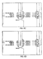
- Figures 9A-9C show an example of building a simple row and column network for a wiring diagram, according to one aspect of the present invention.
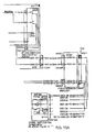
- Figures 10A-10D show an example of navigating near the edge of a drawing, according to one aspect of the present invention.
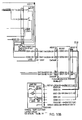
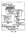
- Figures 13A-13E show an example of using the system and method of the present invention on component location drawing navigation networks
- Figures 14A-14E show an example of using the system and method of the present invention to navigate on parts pages and exploded views.
- a system and method are provided for navigating drawing objects in drawings (or diagrams) using mapped keys on a keyboard. This improves navigation on laptops, workstations, and devices with small form factors such as cell phones and PDA's.
- Figure 1A is a block diagram of a computing system 100A for executing computer executable process steps according to one aspect of the present invention.
- Figure 1 includes a host computer 100 and a monitor 111.
- Monitor 111 may be a CRT type, a LCD type, or any other type of color or monochrome display.
- keyboard 104 for entering data and user commands
- pointing device for example, a mouse
- Computer 100 includes a computer-readable memory storage device 108 for storing readable data. Besides other programs, storage device 108 can store application programs including web browsers and computer executable code, according to the present invention.
- a modem, an integrated services digital network (ISDN) connection, or the like also provide computer 100 with a Network connection 102 - to a network (e.g. the Internet), of computers within a company or entity in the company (for example: an Intranet).
- the network connection 102 allows computer 100 to download data files, application program files and computer-executable process steps embodying the present invention from the Internet.
- Computing system 100 includes an input/output interface 116 that operatively connects output display device such as monitors (111), input devices such as keyboards (104) and pointing device such as a mouse (106) to computing system 100.
- output display device such as monitors (111)
- input devices such as keyboards (104)
- pointing device such as a mouse (106)
- a storage device 120 (similar to storage device 108) also interfaces to computing system 100 through computer bus 118.
- Storage device 120 may be disks, tapes, drums, integrated circuits, or the like, operative to hold data by any means, including magnetically, electrically, optically, and the like.
- Storage device 120 stores operating system program files, application program files, computer-executable process steps, web-browsers and other files. Some of these files are stored on storage device 120 using an installation program. For example, CPU 112 executes computer-executable process steps of an installation program so that CPU 112 can properly execute the application program.
- Random access memory (“RAM”) 124 also interfaces to computer bus 118 to provide CPU 112 with access to memory storage. When executing stored computer-executable process steps from storage device 120, CPU 112 stores and executes the process steps out of RAM 124.
- ROM 122 Read only memory (“ROM”) 122 is provided to store invariant instruction sequences such as start-up instruction sequences or basic input/output operating system (BIOS) sequences.
- BIOS basic input/output operating system
- Network interface 114 may be adapted to one or more of a wide variety of networks, including local area networks, storage area networks, wide area networks, the Internet, and the like.
- a drawing object module 202 collects the drawing objects and stores them in a database 204.
- Drawing objects include, but are not limited to, wires, text references, off-sheet references, and selectable components, such as switches, pins, fuses, and others.
- An object linkage module 206 receives the objects from database 204 and links the objects together building various types of navigation networks (or “networks”), such as a row/column network and wiring diagram network.
- navigation networks or "networks”
- Object linkage module 206 is connected to a user interface 208, such as computing system 100A in Figure 1.
- User interface 208 displays the network containing drawing objects. Keys on keyboard 104 of user interface 208 are mapped to specific commands, such as up, down, left, right and the user navigates the drawing objects using the mapped keys.
- Figure 4 shows an example of keys on a keyboard that have been mapped to specific commands, according to one aspect of the present invention.
- selecting key '4' causes the diagram to show all the wires and selecting key '5' resets paths and components. This is by way of example only, and each user can determine what key is mapped with what command.
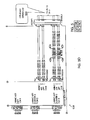
- Figure 5 shows an example of an electronic schematic diagram 508 for use in the present invention.
- Electronic schematic diagram 508 is a wiring diagram having navigable objects.
- Navigable objects include wires 500, text references 502, off-sheet references 504, and selectable components 506 such as switches, pins, fuses, and others.
- the system and method of the present invention allows a user to map keys on a keyboard with specific commands for navigating the drawing objects. For example, five commands could be used to navigate through the network. These commands include (1) Left; (2) Right; (3) Up; (4) Down; and (5) Select. These commands can be mapped to any key on the keyboard. In one aspect, the four cursor keys are mapped to the Left, Right, Up, and Down commands; and Enter is mapped to the Select command.
- Alternative keyboard mapping commands may include North, East, South, West, as well as diagonal navigation with NW, NE, SE, and SW. This increases the complexity of the navigation while yielding more precision and requiring fewer keystrokes to move to a desired object,
- More sophisticated networks link objects in task-related ways. For example, a wiring diagram network might link electrical components with regard to circuit continuity, while a logic diagram might link components with regard to the flow of diagnostic logic,
- the next object is selected by wrapping around to the next logical row or column. For example, navigating to the right off the edge of a drawing results in the left most object in the row below to be selected. Navigating to the left off the edge of a drawing results in the right-most object in the row above being selected. Navigating down off the edge of a drawing results in the top-most object in the next column to the right being selected. Navigating up off the edge of a drawing results in the bottom-most object in the previous column to the left being selected.
- Figures 10A-10D show an example of navigating near the edge of a drawing, according to one aspect of the present invention
- Figure 10A shows a wiring diagram with a pin highlighted near the edge of the drawing. If the user presses a key on the keyboard associated with the command "right” while on the highlighted pin 514, the object to the immediate right of pin 514 is highlighted, a wire 516, as shown in Figure 10B. If navigation is solely using a simple row and column network, the next "right” results in the first object in the next row 518 being selected, as shown in Figure 10C.
- Figure 10D shows that navigating using a more sophisticated "circuit-continuity-following" method results in following the wire to the next object 520 in the circuit.
- Figures 13,A-13E show an example of using the system and method of the present invention on component location drawing navigation networks.
- navigation occurs amongst four component locations 530-536.
- the user navigates to the right as shown in Figure 13B. If the user selects a component location, such as first component location 530, the first navigable object 538 in the location is highlighted as shown in Figure 13C.
- Figure 13D shows an example of the user selecting an off sheet reference to a detail; the system navigates to and chooses the detail on a separate drawing as shown in Figure 13E.
- auto-zooming can be used. This can be very useful while performing certain tasks, especially on devices with small form factors.
Abstract
Description
- This invention relates generally to computing systems, and in particular, to a method and system for managing and navigating among drawing objects.
- Electronic schematic diagrams are used to illustrate complex and non-complex assemblies/systems (used interchangeably throughout this specification). These assemblies often have more than one component or drawing object. Drawing objects, as used in this application, refer to any type of element that is part of a system/assembly. Often the drawing objects are interconnected either individually or as a part of sub-assemblies. For example, in electrical wiring diagrams, drawing objects include modules, plugs, switches, buses, power sources, grounds, wires, connectors, etc.
- Laptops today are commonly used for mobile computing. One may want to view complex drawings on a "hardened" field laptop display screen. This may be difficult because a field laptop may be covered with a rubbery substance to prevent damage and field laptop pointing devices (i.e. joy sticks, tilt pads, touch pads and others) may wear out due to usage in the field.
- This makes it difficult to manipulate complex technical drawings, such as performing pan and zoom operations on individual drawings and sets of drawings, follow circuit logic, navigate through diagnostic decision trees, and examine lengthy bills of materials. Furthermore, selecting/manipulating small objects using hardened joysticks, tilt-pads, and other devices can be very challenging.
- Users of technical drawings on everyday laptops and workstations have similar problems. Users move their hands back and forth between keys and cursor pointer devices to select and manipulate drawing objects.
- Therefore, what is needed an efficient system and method for users to examine and manipulate complex technical drawings.
- In one aspect of the present invention, a method for navigating drawings on a computing system, comprising: loading drawings and associated object data; arranging the drawings and the associated object data into at least one network; selecting parameters for mapping keys in a keyboard; displaying the drawings; and manipulating the drawings.
- In another aspect of the present invention, a system for navigating drawings on a computing system, comprising: a drawing object module for collecting the drawing objects and storing the drawing objects in a database; an object linkage module for receiving the drawing objects from the database and linking the drawing objects together into at least one network; and a user interface, having a keyboard, for displaying the at least one network, wherein keys on the keyboard are mapped to specific commands, and wherein a user navigates the drawing objects using the mapped keys.
- Figure 1A shows a block diagram of a computing system for executing process steps, according to one aspect of the present invention.
- Figure 1B shows the internal architecture of the computing system of Figure 1;
- Figure 2 shows a system for navigating drawing objects in a drawing, according to one aspect of the present invention;
- Figure 3 shows a process flow diagram for navigating complex drawings, according to one aspect of the present invention;
- Figure 4 shows an example of keyboard mapping, according to one aspect of the present invention;
- Figure 5 (Figures 5A-5D) shows an example of a schematic diagram for use in navigating objects, according to one aspect of the present invention;
- Figures 6A-6D show different methods for highlighting objects while navigating through a network;
- Figures 7A-7B show an example of navigation and object selection results on a wiring diagram using a simple row and column network;
- Figures 8A-8G show an example of navigating on a schematic and highlighting different objects, according to one aspect of the present invention;
- Figures 9A-9C show an example of building a simple row and column network for a wiring diagram, according to one aspect of the present invention;
- Figures 10A-10D show an example of navigating near the edge of a drawing, according to one aspect of the present invention;
- Figures 11A-11D show an example of-navigating objects in a diagnostic flow chart, according to one aspect of the present invention;
- Figure 12 (Figures 12A-12B) is an example of navigating among objects in a table, according to one aspect of the present invention;
- Figures 13A-13E show an example of using the system and method of the present invention on component location drawing navigation networks; and
- Figures 14A-14E show an example of using the system and method of the present invention to navigate on parts pages and exploded views.
- In one aspect of the present invention, a system and method are provided for navigating drawing objects in drawings (or diagrams) using mapped keys on a keyboard. This improves navigation on laptops, workstations, and devices with small form factors such as cell phones and PDA's.
- To facilitate an understanding of the preferred embodiment, the general architecture and operation of a computing system will be described first. The specific process under the preferred embodiment will then be described with reference to the general architecture.
- Computing System
- Figure 1A is a block diagram of a
computing system 100A for executing computer executable process steps according to one aspect of the present invention. Figure 1 includes ahost computer 100 and amonitor 111. Monitor 111 may be a CRT type, a LCD type, or any other type of color or monochrome display. - Also provided with
computer 100 are akeyboard 104 for entering data and user commands, and a pointing device (for example, a mouse) 106 for processing objects displayed onmonitor 111. -
Computer 100 includes a computer-readablememory storage device 108 for storing readable data. Besides other programs,storage device 108 can store application programs including web browsers and computer executable code, according to the present invention. - According to one aspect of the present invention,
computer 100 can also use removable storage device 110 (for example: floppy disk drive, memory stick, CD-ROM., or CD R/W (read/write) or other device) for storing data files, application program files, and computer executable process steps embodying the present invention. - A modem, an integrated services digital network (ISDN) connection, or the like also provide
computer 100 with a Network connection 102 - to a network (e.g. the Internet), of computers within a company or entity in the company (for example: an Intranet). Thenetwork connection 102 allowscomputer 100 to download data files, application program files and computer-executable process steps embodying the present invention from the Internet. - Figure 1B shows a top-level block diagram showing the internal functional architecture of a computing system 100 (
host computer 100 or computer 100) that may be used to execute the computer-executable process steps, according to one aspect of the present invention. As detailed in Figure 1B,computing system 100 includes a central processing unit (CPU) 112 for executing computer-executable process steps and interfaces with acomputer bus 118. -
Computing system 100 includes an input/output interface 116 that operatively connects output display device such as monitors (111), input devices such as keyboards (104) and pointing device such as a mouse (106) to computingsystem 100. - A storage device 120 (similar to storage device 108) also interfaces to computing
system 100 throughcomputer bus 118.Storage device 120 may be disks, tapes, drums, integrated circuits, or the like, operative to hold data by any means, including magnetically, electrically, optically, and the like.Storage device 120 stores operating system program files, application program files, computer-executable process steps, web-browsers and other files. Some of these files are stored onstorage device 120 using an installation program. For example,CPU 112 executes computer-executable process steps of an installation program so thatCPU 112 can properly execute the application program. - Random access memory ("RAM") 124 also interfaces to
computer bus 118 to provideCPU 112 with access to memory storage. When executing stored computer-executable process steps fromstorage device 120,CPU 112 stores and executes the process steps out ofRAM 124. - Read only memory ("ROM") 122 is provided to store invariant instruction sequences such as start-up instruction sequences or basic input/output operating system (BIOS) sequences.
-
Computing system 100 can be connected to other computing systems through thenetwork interface 114 usingcomputer bus 118.Network interface 114 may be adapted to one or more of a wide variety of networks, including local area networks, storage area networks, wide area networks, the Internet, and the like. - It is noteworthy that the present invention is not limited to the layout shown in Figures 1A and 1B. For example, hand-held computers, notebook or laptop computers, set-top boxes or any other computing system (wired or wireless) capable of running computer-executable process steps, as described below, may be used to implement the various aspects of the present invention.
- Turning to Figure 2, a
system 200 for navigating drawing objects in a drawing, according to one aspect of the present invention, is shown. Insystem 200, adrawing object module 202 collects the drawing objects and stores them in adatabase 204. Drawing objects include, but are not limited to, wires, text references, off-sheet references, and selectable components, such as switches, pins, fuses, and others. - An
object linkage module 206 receives the objects fromdatabase 204 and links the objects together building various types of navigation networks (or "networks"), such as a row/column network and wiring diagram network. Automatically understanding the content and recognizing the objects in these drawings is the subject ofUS Patent 6,606,731 entitled "Intelligent wiring diagram system", issued on August 13, 2003;US Patent 6,766,331 entitled "Method, computer program product, and system for creating and viewing an intelligent graphics file including parts information", issued on July 20, 2004;US Patent application 20030025734 entitled, "Method, computer program product, and system for performing automated linking between sheets of a drawing set", Serial. Number09/971,283, filed on October 4, 2001 Serial Number 11/339,599, filed on January 25, 2006 -
Object linkage module 206 is connected to auser interface 208, such ascomputing system 100A in Figure 1.User interface 208 displays the network containing drawing objects. Keys onkeyboard 104 ofuser interface 208 are mapped to specific commands, such as up, down, left, right and the user navigates the drawing objects using the mapped keys. -
Keyboard 104 is mapped based on the type of network being viewed and can continually be re-mapped based on the needs of the user. For example, if the user was viewing a row/column network, the user might want to use the letters 'R' and 'C' which will help remind the user to use the key 'R' to move by row and the key 'C' to move by column. - Process Flow:
- Figure 3 shows a process flow diagram, for navigating complex drawings, according to one aspect of the present invention. Schematic diagrams (or drawings) are automatically generated. Automatically generating drawings is the subject matter of US Patent Application entitled "Method and system for automatically generating schematics".
Serial Number 11/346,103, filed on October 2, 2006 - In step S300, the drawings and associated object data are loaded. In step S301, networks are built from the drawings and object data. A network can be a loose arrangement of objects in rows or columns, or a more sophisticated task-based arrangement of objects. (The networks can be pre-computed, computed when they are loaded into a viewer or computed on the fly.) In step S302, parameters are selected for keyboard mapping. Using keys allows the user to navigate through the objects in the drawings in a task based way. The different objects can be displayed based on the selected parameters. These parameters included, but are not limited to, keyboard command mapping (i.e. mapping specific command to specific keys on keyboard 104), navigation method (i.e., simple row and column navigation or task-based navigation based on the type of drawing and its contents), and object filtering (i.e., for a wiring diagram, "All object;" "Off-sheet references only;" "Wires only;" "Components only;" "Text references only;"). The user can then interact with the drawing objects based on these parameters.
- In step S303, the drawings are displayed on
user interface 208. Once the drawings have been displayed, the user can manipulate the drawings by selecting or changing the type of network (for example, from a row/column network to a flow chart network) in step S304A; changing the mapping for the keyboard commands in step S304B; or manipulating the drawings through the keyboard commands in step S304C. Steps S304A-S304C may occur in any order or simultaneously. Furthermore, the user can change the network at run time; can change the key board mapping at run time or re-compute the network and key mapping. - Different types of networks include a row/column network and a network that follows the wiring continuity. The user can select either of these networks to manipulate the drawings depending on the task or what is most convenient. For example, if the user is reviewing all the connector labels on a drawing, the row/column network would be the most appropriate network or the user can select a wiring diagram network if following the wire continuity is more preferable.
- Figure 4 shows an example of keys on a keyboard that have been mapped to specific commands, according to one aspect of the present invention. For example, as can be seen in Figure 4, selecting key '4' causes the diagram to show all the wires and selecting key '5' resets paths and components. This is by way of example only, and each user can determine what key is mapped with what command.
- Figures 5-14 show examples of using the system and method of the present invention with different types of networks,
- Figure 5 (Figures 5A-5D) shows an example of an electronic schematic diagram 508 for use in the present invention. Electronic schematic diagram 508 is a wiring diagram having navigable objects. Navigable objects include
wires 500, text references 502, off-sheet references 504, andselectable components 506 such as switches, pins, fuses, and others. The system and method of the present invention allows a user to map keys on a keyboard with specific commands for navigating the drawing objects. For example, five commands could be used to navigate through the network. These commands include (1) Left; (2) Right; (3) Up; (4) Down; and (5) Select. These commands can be mapped to any key on the keyboard. In one aspect, the four cursor keys are mapped to the Left, Right, Up, and Down commands; and Enter is mapped to the Select command. Alternative keyboard mapping commands may include North, East, South, West, as well as diagonal navigation with NW, NE, SE, and SW. This increases the complexity of the navigation while yielding more precision and requiring fewer keystrokes to move to a desired object, - The simplest type of network connects objects in loose rows and columns where Left and Right commands move among objects in rows; and Up and Down commands move among objects in columns. The select command performs an object-specific action. For example, selecting an off sheet reference causes the system to navigate to the reference; selecting a wire highlights its circuit network, and selecting a Reference Designator causes the system to show tabular data associated with the component.
- More sophisticated networks link objects in task-related ways. For example, a wiring diagram network might link electrical components with regard to circuit continuity, while a logic diagram might link components with regard to the flow of diagnostic logic,
- Several methods may be used to identify an object on the drawing selected by the user. Figures 6A-6D show different methods of identifying objects while navigating through a drawing. In Figure 6A, objects are identified by highlighting text. In Figure 6B, objects are identified by magnifying text. In Figure 6C, the objects are identified by highlighting the objects. In Figure 6D, the objects are identified by placing a box around the objects.
- Figures 7A-7B show an example of navigation on a wiring diagram using a row and column network. Figure 7A shows an enlarged view of the wiring diagram in Figure 5, where the user has navigated to '13' which is a text reference associated with a pin in a connector. Once the object has been highlighted, in this
case pin 13, the user can select the highlighted object to view the object in greater detail, as shown in Figure 7B. Selectingpin 13 causes a table to be displayed showing data related topin 13, such as the reference description. - Figures 8A-8G show a user navigating on a drawing having a row/column network and highlighting different objects. In Figure 8A,
pin 13 is highlighted. The user can navigate on the schematic in four different directions: up, down, right, and left. Pressing a key on the keyboard associated with the command "up" causes the text reference forpin 12 to be highlighted as it is directly above the text reference forpin 13, as shown in Figure 8B. If the user presses a key on the keyboard associated with the command "down", the text reference forpin 24 is highlighted as it is directly below the text reference forpin 13, as shown in Figure 8C. - If the user presses a key on the keyboard associated with the command "left", a wire is highlighted. The wire is the next logical object to the left in the row where the text reference for
pin 13 is located, as shown in Figure 8D. If the user presses a key on the keyboard associated with the command "select", the circuit path for the wire is highlighted as shown in Figure 8E. If the user presses a key on the keyboard associated with the command "right", a wire is highlighted. The wire is the next logical object to the right in the row where the text reference forpin 13 is located, as shown in Figure 8F. If the user presses a key on the keyboard associated with the command "right" while on the wire of Figure 8F, a text reference for this wire is then highlighted, as shown in Figure 8G. The wire is the next logical object to the right in this row, since it was reached from the left. Navigating to the right again causes the same wire to be highlighted again as shown in Figure 8E. Navigating again to the right highlights pin 2TR. - If the user navigates off the edge of a drawing, the next object is selected by wrapping around to the next logical row or column. For example, navigating to the right off the edge of a drawing results in the left most object in the row below to be selected. Navigating to the left off the edge of a drawing results in the right-most object in the row above being selected. Navigating down off the edge of a drawing results in the top-most object in the next column to the right being selected. Navigating up off the edge of a drawing results in the bottom-most object in the previous column to the left being selected.
- Figures 9A-9C show an example of building a simple row and column network for a wiring diagram, according to one aspect of the present invention. First, as shown in Figure 9A, a wiring diagram containing embedded objects is utilized and Figure 9B shows the embedded objects in the wiring diagram, such as wires, text references, off-sheet references, and electrical components. Next as shown in Figure 9C, a
center 512 is computed for each object; for wires a center is computed for each segment. Then rows and columns are formed using thecenters 512. If an object is within a small distance of another row or column it is included in that row or column. Movement through the network then proceeds as described above, from object to object in a given row or column. - Figures 10A-10D show an example of navigating near the edge of a drawing, according to one aspect of the present invention Figure 10A shows a wiring diagram with a pin highlighted near the edge of the drawing. If the user presses a key on the keyboard associated with the command "right" while on the highlighted
pin 514, the object to the immediate right ofpin 514 is highlighted, awire 516, as shown in Figure 10B. If navigation is solely using a simple row and column network, the next "right" results in the first object in thenext row 518 being selected, as shown in Figure 10C. Figure 10D shows that navigating using a more sophisticated "circuit-continuity-following" method results in following the wire to thenext object 520 in the circuit. For many tasks, following the circuit will be much more useful than simply going to the left-most object in the next row. A similar method can be applied to navigate through hydraulic or pneumatic flows in schematic drawings. The method for building the network is similar to the method for building a simple row and column network. Centers of objects are computed as before. Electrical connectivity is used to connect objects in the network instead of row and column organization. After electrical links are made, other links are filled in using rows and columns as above. - Figures 11A-11D show an example of navigating objects in a diagnostic flow chart, according to one aspect of the present invention. Objects in a diagnostic flow chart can include, but are not limited to, logic blocks, selectable contents of logic blocks such as references to other manuals, answers to diagnostic questions, off-sheet references, and other objects. Figure 11A shows a diagnostic flow chart of a fault isolation manual. The flow chart comprises logic blocks that contain questions; the answers to the questions point the user to subsequent logic blocks. A logic tree may span many pages and even several volumes of the manual, and eventually may lead the user to another manual for repair, replacement, or further diagnosis. In Figure 11A, the user has navigated to a
first logic block 522. Using simple row and column logic, the user can move right fromfirst logic block 522 to the text answer, "No" causing asecond logic block 524 to be highlighted, as shown in Figure 11B. However, the system and method of the present invention knows the logical connections among objects and can make a better navigation choice. When the user moves Right, logic block 20 (or second logic block 524) is chosen. When the user selects a logic block, such assecond logic block 524, the firstnavigable object 526 inblock 524 is highlighted, as shown in Figure 11C. Navigating down inblock 524 causes the nextnavigable object 528 to be highlighted, as shown in Figure 11D. - Figure 12 (Figures 12A-12B) is an example of a table where the objects are arranged in a row and column network capable of navigation.
- Figures 13,A-13E show an example of using the system and method of the present invention on component location drawing navigation networks. As shown in Figure 13A, navigation occurs amongst four component locations 530-536. To go from the
first component location 530 to thesecond component location 532, the user navigates to the right as shown in Figure 13B. If the user selects a component location, such asfirst component location 530, the firstnavigable object 538 in the location is highlighted as shown in Figure 13C. Figure 13D shows an example of the user selecting an off sheet reference to a detail; the system navigates to and chooses the detail on a separate drawing as shown in Figure 13E. - Figures 14A-14E show an example of using the system and method of the present invention to navigate on parts pages and exploded views. Drawing objects include, but are not limited to, callouts, details, item numbers, zones, and stations. Figure 14A shows selecting
callout C 540 causing the system to navigate tocallout C 540. Figure 14B shows the ability to enhance parts page navigation by going beyond simple row and column linkage. For example, if using simple row and column linkage in Figure 14C and moving up fromitem 942 will lead toitem 936 in Figure 14C. As shown in Figures 14D and 14E, task-based linkage can be used to navigate to items around the current detail. Here the user enters Up, Left, and Left, to navigate to items around the current detail. - In an additional embodiment of the present invention, auto-zooming can be used. This can be very useful while performing certain tasks, especially on devices with small form factors.
- In summary, object-based navigation, provides a rapid, pointer (e.g. mouse, touch pad, joystick) free method for navigating complex technical drawings. The general row and column network can be applied to any drawing. Even more efficient networks can be created based on specialized knowledge of the content of particular classes of drawings.
Claims (14)
- A method (200) for navigating drawings on a computing system (200), comprising:loading (S300) drawings and associated object data;arranging (S301) the drawings and the associated object data into at least one network;selecting parameters (S302) for mapping keys in a keyboard (104);displaying (S303) the drawings; andmanipulating (S304C) the drawings.
- The method of Claim, 1, wherein the parameters include keyboard command mapping, navigation method, and object filtering.
- The method of claim 1 or 2, wherein the drawings are manipulated by changing (S304A) the type of network.
- The method of claim 1 or 2, wherein the drawings are manipulated by re-mapping (S304B) the keys in the keyboard.
- The method of claim 1, wherein the drawings are manipulated using keyboard commands.
- The method of claim 3, wherein the types of networks include row/column network, a flow chart network, a wiring diagram network, and a component location drawing navigation network.
- The method of any of claims 1-6, further comprising selecting a drawing object to view the details of the drawing object.
- The method of claim. 7, wherein the drawing objects include wires, text references, off-sheet references, and selectable components.
- The method of claim 8, wherein the selectable components include switches, pins and fuses.
- A system (200) used for navigating drawings, comprising:a drawing object module (202) for collecting drawing objects and storing the drawing objects in a database (204);an object linkage module (206) for receiving the drawing objects from the database (204) and linking the drawing objects together into at least one network; anda user interface (208), having a keyboard (104), for displaying the at least one network, wherein keys on the keyboard (104) are mapped to specific commands, and wherein a user navigates the drawing objects using the mapped keys.
- The system of claim 10, wherein a drawing object is selected for viewing details of the drawing object.
- The system of claim 10 or 11, wherein the drawing objects includes wires (500), text references (502), off-sheet references (504), and selectable components (506).
- The system of any of claims 10 - 12, wherein the type of the at least one network is changed.
- The system of claim 13, wherein the type of the at least one network include a row/column network, a flow chart network, a wiring diagram network, and a component location drawing navigation network.
Applications Claiming Priority (1)
| Application Number | Priority Date | Filing Date | Title |
|---|---|---|---|
| US11/538,028 US8214789B2 (en) | 2006-10-02 | 2006-10-02 | Method and system for keyboard managing and navigating among drawing objects |
Publications (2)
| Publication Number | Publication Date |
|---|---|
| EP1909204A2 true EP1909204A2 (en) | 2008-04-09 |
| EP1909204A3 EP1909204A3 (en) | 2011-03-23 |
Family
ID=39016196
Family Applications (1)
| Application Number | Title | Priority Date | Filing Date |
|---|---|---|---|
| EP07019320A Withdrawn EP1909204A3 (en) | 2006-10-02 | 2007-10-02 | Method and system for keyboard managing and navigating among drawing objects |
Country Status (2)
| Country | Link |
|---|---|
| US (1) | US8214789B2 (en) |
| EP (1) | EP1909204A3 (en) |
Cited By (1)
| Publication number | Priority date | Publication date | Assignee | Title |
|---|---|---|---|---|
| EP2660740A3 (en) * | 2012-05-03 | 2016-10-19 | The Boeing Company | Component configuration system and methods of operating same |
Families Citing this family (12)
| Publication number | Priority date | Publication date | Assignee | Title |
|---|---|---|---|---|
| US7705849B2 (en) * | 2007-03-01 | 2010-04-27 | The Boeing Company | Intelligent lamm schematics |
| US20080301613A1 (en) * | 2007-06-01 | 2008-12-04 | Simon Edward Holdsworth | Designing wiring harnesses |
| US7735044B2 (en) * | 2007-06-05 | 2010-06-08 | Simon Edward Holdsworth | Combination of ground devices in wiring harness designs |
| US20090157209A1 (en) * | 2007-12-14 | 2009-06-18 | Simon Edward Holdsworth | Wire option expressions in wiring harness designs |
| CN102375899A (en) * | 2010-08-16 | 2012-03-14 | 鸿富锦精密工业(深圳)有限公司 | Pattern width detection system and pattern width detection method |
| JP5874339B2 (en) * | 2011-11-18 | 2016-03-02 | 富士通株式会社 | Circuit design program, circuit design method, and circuit design apparatus |
| DE102014207874A1 (en) * | 2014-04-25 | 2015-10-29 | Siemens Aktiengesellschaft | Method for the automated creation of a data record characterizing a technical drawing |
| US10719642B2 (en) | 2018-10-17 | 2020-07-21 | Caterpillar Inc. | Automated generation of electronics schematics with single wire tracing |
| IT201900000625A1 (en) * | 2019-01-15 | 2020-07-15 | Texa Spa | METHOD OF DRAWING UP ELECTRICAL DIAGRAMS |
| US20220091707A1 (en) | 2020-09-21 | 2022-03-24 | MBTE Holdings Sweden AB | Providing enhanced functionality in an interactive electronic technical manual |
| US20220261530A1 (en) | 2021-02-18 | 2022-08-18 | MBTE Holdings Sweden AB | Providing enhanced functionality in an interactive electronic technical manual |
| US11947906B2 (en) | 2021-05-19 | 2024-04-02 | MBTE Holdings Sweden AB | Providing enhanced functionality in an interactive electronic technical manual |
Citations (1)
| Publication number | Priority date | Publication date | Assignee | Title |
|---|---|---|---|---|
| US20050212823A1 (en) * | 2004-03-29 | 2005-09-29 | Uthe Robert T | System, method and software for intelligent zooming in a user interface |
Family Cites Families (13)
| Publication number | Priority date | Publication date | Assignee | Title |
|---|---|---|---|---|
| US5008847A (en) | 1983-01-21 | 1991-04-16 | The Laitram Corporation | Cursor selected keyboard keys displayed on the computer screen for entering alphanumeric characters and instructions, particularly for creating computer aided design and drafting patterns |
| US6516456B1 (en) * | 1997-01-27 | 2003-02-04 | Unisys Corporation | Method and apparatus for selectively viewing nets within a database editor tool |
| US6606731B1 (en) | 1999-08-05 | 2003-08-12 | The Boeing Company | Intelligent wiring diagram system |
| JP4325075B2 (en) * | 2000-04-21 | 2009-09-02 | ソニー株式会社 | Data object management device |
| CA2315456C (en) * | 2000-08-09 | 2009-10-13 | Semiconductor Insights Inc. | Schematic organization tool |
| US7200271B2 (en) | 2001-03-29 | 2007-04-03 | The Boeing Company | Method, computer program product, and system for performing automated text recognition and text search within a graphic file |
| US6766331B2 (en) | 2001-03-29 | 2004-07-20 | The Boeing Company | Method, computer program product, and system for creating and viewing an intelligent graphics file including parts information |
| US7246328B2 (en) * | 2001-03-29 | 2007-07-17 | The Boeing Company | Method, computer program product, and system for performing automated linking between sheets of a drawing set |
| US6996806B2 (en) * | 2001-09-21 | 2006-02-07 | International Business Machines Corporation | Graphical view of program structure during debugging session |
| US7383158B2 (en) * | 2002-04-16 | 2008-06-03 | Trane International Inc. | HVAC service tool with internet capability |
| US8020096B2 (en) * | 2003-06-24 | 2011-09-13 | International Business Machines Corporation | Method and system for providing integrated hot key configuration |
| US7529648B2 (en) | 2003-11-24 | 2009-05-05 | The Boeing Company | Method, system and computer program product for automatically generating a subset of task-based components from engineering and maintenance data |
| JP4318047B2 (en) * | 2005-06-06 | 2009-08-19 | ソニー株式会社 | 3D object display device, 3D object switching display method, and 3D object display program |
-
2006
- 2006-10-02 US US11/538,028 patent/US8214789B2/en active Active
-
2007
- 2007-10-02 EP EP07019320A patent/EP1909204A3/en not_active Withdrawn
Patent Citations (1)
| Publication number | Priority date | Publication date | Assignee | Title |
|---|---|---|---|---|
| US20050212823A1 (en) * | 2004-03-29 | 2005-09-29 | Uthe Robert T | System, method and software for intelligent zooming in a user interface |
Cited By (1)
| Publication number | Priority date | Publication date | Assignee | Title |
|---|---|---|---|---|
| EP2660740A3 (en) * | 2012-05-03 | 2016-10-19 | The Boeing Company | Component configuration system and methods of operating same |
Also Published As
| Publication number | Publication date |
|---|---|
| US8214789B2 (en) | 2012-07-03 |
| US20080082948A1 (en) | 2008-04-03 |
| EP1909204A3 (en) | 2011-03-23 |
Similar Documents
| Publication | Publication Date | Title |
|---|---|---|
| US8214789B2 (en) | Method and system for keyboard managing and navigating among drawing objects | |
| US8584044B2 (en) | Localized thumbnail preview of related content during spatial browsing | |
| US6715132B1 (en) | Datasheet browsing and creation with data-driven datasheet tabs within a microcontroller design tool | |
| US4984152A (en) | System for controlling computer processing utilizing a multifunctional cursor with decoupling of pointer and image functionalities in space and time | |
| US6404443B1 (en) | Three-dimensional graphical user interface for managing screen objects | |
| US9336267B2 (en) | Method and system for navigation and visualization of data in relational and/or multidimensional databases | |
| US6707454B1 (en) | Systems and methods for visualizing multi-dimensional data in spreadsheets and other data structures | |
| US8855983B2 (en) | Graphical user interface for viewing or editing an executable block diagram model | |
| US7441207B2 (en) | Method and system for improved viewing and navigation of content | |
| US20110191344A1 (en) | Automatic organization of browsing histories | |
| US20120054653A1 (en) | Visualizing user interfaces | |
| US20090300541A1 (en) | Apparatus and method for positioning windows on a display | |
| US20120017161A1 (en) | System and method for user interface | |
| CN102077159A (en) | Menus with translucency and live preview | |
| US20060250369A1 (en) | Keyboard controls for customizing table layouts | |
| US6141008A (en) | Method and system for providing size adjustment for a maximized window in a computer system graphical user interface | |
| US20070198620A1 (en) | Modeling Environment with Generally Accessible Variables for Dynamically Linked Mathematical Representations | |
| EP2137643A1 (en) | Method and system for navigation and visualization of data in relational and/or multidimensional databases | |
| CN106919639A (en) | A kind of processing method and processing device of data loading | |
| Subramonyam et al. | Smartcues: a multitouch query approach for details-on-demand through dynamically computed overlays | |
| WO2012106047A1 (en) | A method for multiple pass symbol and components-based visual object searching of documents | |
| CN105975154A (en) | Application icon search method and mobile terminal | |
| CN103761307A (en) | Data processing device and data processing method | |
| Knight et al. | Mediating diverse visualisations for comprehension | |
| KR100696284B1 (en) | Auxiliary device serving both as an auxiliary display device and and an auxiliary input device with respect to an electronic device |
Legal Events
| Date | Code | Title | Description |
|---|---|---|---|
| PUAI | Public reference made under article 153(3) epc to a published international application that has entered the european phase |
Free format text: ORIGINAL CODE: 0009012 |
|
| AK | Designated contracting states |
Kind code of ref document: A2 Designated state(s): AT BE BG CH CY CZ DE DK EE ES FI FR GB GR HU IE IS IT LI LT LU LV MC MT NL PL PT RO SE SI SK TR |
|
| AX | Request for extension of the european patent |
Extension state: AL BA HR MK RS |
|
| PUAL | Search report despatched |
Free format text: ORIGINAL CODE: 0009013 |
|
| AK | Designated contracting states |
Kind code of ref document: A3 Designated state(s): AT BE BG CH CY CZ DE DK EE ES FI FR GB GR HU IE IS IT LI LT LU LV MC MT NL PL PT RO SE SI SK TR |
|
| AX | Request for extension of the european patent |
Extension state: AL BA HR MK RS |
|
| 17P | Request for examination filed |
Effective date: 20110728 |
|
| AKX | Designation fees paid |
Designated state(s): AT BE BG CH CY CZ DE DK EE ES FI FR GB GR HU IE IS IT LI LT LU LV MC MT NL PL PT RO SE SI SK TR |
|
| 17Q | First examination report despatched |
Effective date: 20140113 |
|
| STAA | Information on the status of an ep patent application or granted ep patent |
Free format text: STATUS: THE APPLICATION HAS BEEN WITHDRAWN |
|
| 18W | Application withdrawn |
Effective date: 20161209 |