EP1908685A2 - Motor balanced active user interface assembly - Google Patents
Motor balanced active user interface assembly Download PDFInfo
- Publication number
- EP1908685A2 EP1908685A2 EP07117684A EP07117684A EP1908685A2 EP 1908685 A2 EP1908685 A2 EP 1908685A2 EP 07117684 A EP07117684 A EP 07117684A EP 07117684 A EP07117684 A EP 07117684A EP 1908685 A2 EP1908685 A2 EP 1908685A2
- Authority
- EP
- European Patent Office
- Prior art keywords
- user interface
- feedback
- coupled
- motor
- flight control
- Prior art date
- Legal status (The legal status is an assumption and is not a legal conclusion. Google has not performed a legal analysis and makes no representation as to the accuracy of the status listed.)
- Granted
Links
Images


Classifications
-
- B—PERFORMING OPERATIONS; TRANSPORTING
- B64—AIRCRAFT; AVIATION; COSMONAUTICS
- B64C—AEROPLANES; HELICOPTERS
- B64C13/00—Control systems or transmitting systems for actuating flying-control surfaces, lift-increasing flaps, air brakes, or spoilers
- B64C13/02—Initiating means
- B64C13/04—Initiating means actuated personally
- B64C13/042—Initiating means actuated personally operated by hand
- B64C13/0421—Initiating means actuated personally operated by hand control sticks for primary flight controls
-
- B—PERFORMING OPERATIONS; TRANSPORTING
- B64—AIRCRAFT; AVIATION; COSMONAUTICS
- B64C—AEROPLANES; HELICOPTERS
- B64C13/00—Control systems or transmitting systems for actuating flying-control surfaces, lift-increasing flaps, air brakes, or spoilers
- B64C13/02—Initiating means
- B64C13/04—Initiating means actuated personally
- B64C13/042—Initiating means actuated personally operated by hand
- B64C13/0425—Initiating means actuated personally operated by hand for actuating trailing or leading edge flaps, air brakes or spoilers
-
- B—PERFORMING OPERATIONS; TRANSPORTING
- B64—AIRCRAFT; AVIATION; COSMONAUTICS
- B64C—AEROPLANES; HELICOPTERS
- B64C13/00—Control systems or transmitting systems for actuating flying-control surfaces, lift-increasing flaps, air brakes, or spoilers
- B64C13/24—Transmitting means
- B64C13/26—Transmitting means without power amplification or where power amplification is irrelevant
- B64C13/28—Transmitting means without power amplification or where power amplification is irrelevant mechanical
- B64C13/345—Transmitting means without power amplification or where power amplification is irrelevant mechanical with artificial feel
-
- B—PERFORMING OPERATIONS; TRANSPORTING
- B64—AIRCRAFT; AVIATION; COSMONAUTICS
- B64C—AEROPLANES; HELICOPTERS
- B64C13/00—Control systems or transmitting systems for actuating flying-control surfaces, lift-increasing flaps, air brakes, or spoilers
- B64C13/02—Initiating means
- B64C13/04—Initiating means actuated personally
- B64C13/044—Initiating means actuated personally operated by feet, e.g. pedals
-
- G—PHYSICS
- G05—CONTROLLING; REGULATING
- G05G—CONTROL DEVICES OR SYSTEMS INSOFAR AS CHARACTERISED BY MECHANICAL FEATURES ONLY
- G05G9/00—Manually-actuated control mechanisms provided with one single controlling member co-operating with two or more controlled members, e.g. selectively, simultaneously
- G05G9/02—Manually-actuated control mechanisms provided with one single controlling member co-operating with two or more controlled members, e.g. selectively, simultaneously the controlling member being movable in different independent ways, movement in each individual way actuating one controlled member only
- G05G9/04—Manually-actuated control mechanisms provided with one single controlling member co-operating with two or more controlled members, e.g. selectively, simultaneously the controlling member being movable in different independent ways, movement in each individual way actuating one controlled member only in which movement in two or more ways can occur simultaneously
- G05G9/047—Manually-actuated control mechanisms provided with one single controlling member co-operating with two or more controlled members, e.g. selectively, simultaneously the controlling member being movable in different independent ways, movement in each individual way actuating one controlled member only in which movement in two or more ways can occur simultaneously the controlling member being movable by hand about orthogonal axes, e.g. joysticks
- G05G2009/04766—Manually-actuated control mechanisms provided with one single controlling member co-operating with two or more controlled members, e.g. selectively, simultaneously the controlling member being movable in different independent ways, movement in each individual way actuating one controlled member only in which movement in two or more ways can occur simultaneously the controlling member being movable by hand about orthogonal axes, e.g. joysticks providing feel, e.g. indexing means, means to create counterforce
-
- Y—GENERAL TAGGING OF NEW TECHNOLOGICAL DEVELOPMENTS; GENERAL TAGGING OF CROSS-SECTIONAL TECHNOLOGIES SPANNING OVER SEVERAL SECTIONS OF THE IPC; TECHNICAL SUBJECTS COVERED BY FORMER USPC CROSS-REFERENCE ART COLLECTIONS [XRACs] AND DIGESTS
- Y10—TECHNICAL SUBJECTS COVERED BY FORMER USPC
- Y10T—TECHNICAL SUBJECTS COVERED BY FORMER US CLASSIFICATION
- Y10T74/00—Machine element or mechanism
- Y10T74/20—Control lever and linkage systems
- Y10T74/20012—Multiple controlled elements
Definitions
- the present invention relates to user interfaces and, more particularly, to a user interface assembly that includes one or more motors to provide haptic feedback and that is mass balanced by a haptic feedback motor.
- Aircraft typically include a plurality of flight control surfaces that, when controllably positioned, guide the movement of the aircraft from one destination to another.
- the number and type of flight control surfaces included in an aircraft may vary, but typically include both primary flight control surfaces and secondary flight control surfaces.
- the primary flight control surfaces are those that are used to control aircraft movement in the pitch, yaw, and roll axes
- the secondary flight control surfaces are those that are used to influence the lift or drag (or both) of the aircraft.
- the primary flight control surfaces typically include a pair of elevators, a rudder, and a pair of ailerons
- the secondary flight control surfaces typically include a plurality of flaps, slats, and spoilers.
- the positions of the aircraft flight control surfaces are typically controlled using a flight control surface actuation system.
- the flight control surface actuation system in response to position commands that originate from either the flight crew or an aircraft autopilot, moves the aircraft flight control surfaces to the commanded positions. In most instances, this movement is effected via actuators that are coupled to the flight control surfaces.
- the position commands that originate from the flight crew are supplied via some type of input control mechanism.
- many aircraft include two yoke and wheel type of mechanisms, one for the pilot and one for the co-pilot. Either mechanism can be used to generate desired flight control surface position commands.
- control stick type mechanisms which may be implemented as either side sticks or center sticks. Most notably in aircraft that employ a fly-by-wire system. Similar to the traditional yoke and wheel mechanisms, it is common to include multiple control stick mechanisms in the cockpit, one for the pilot and one for the co-pilot.
- control stick mechanisms are implemented with some type of mass balance, such as counterbalance weights, to alleviate a potentially large moment that may exist when an aircraft experiences accelerations resulting from longitudinal and lateral accelerations.
- counterbalance weights can be undesirable in some instances.
- the counterbalance weights, when included, are in addition to the mounting, control, and feedback hardware associated with the control stick mechanism.
- overall size envelope and weight may increase, which may result in a concomitant increase in costs.
- an active user interface assembly includes a housing, a user interface, and a feedback motor.
- the user interface is coupled to and extends from the housing, and is rotatable, from a null position, about an axis.
- the feedback motor is coupled to the user interface and is adapted to be selectively energized.
- the feedback motor is operable, upon being energized, to supply a feedback force to the user interface that opposes user interface movement about the axis.
- the feedback motor is disposed such that its center of gravity is located at a position relative to the user interface to mass balance the user interface when it is in the null position.
- an active user interface assembly in another exemplary embodiment, includes a housing, a user interface, a first feedback motor, and a second feedback motor.
- the user interface is coupled to and extends from the housing, and is rotatable, from a null position, about a first axis and a second axis.
- the first and second axes are perpendicular.
- the first feedback motor is coupled to the user interface and is disposed such that its center of gravity is located at a first position relative to the user interface.
- the first feedback motor is adapted to be selectively energized and is operable, upon being energized, to supply a feedback force to the user interface that opposes user interface movement about the first axis.
- the second feedback motor is coupled to the user interface and is disposed such that its center of gravity is located at a second position relative to the user interface.
- the second feedback motor is adapted to be selectively energized and is operable, upon being energized, to supply a feedback force to the user interface that opposes user interface movement about the second axis. At least one of the first position and the second position are selected to mass balance the user interface when it is in the null position.
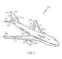
- FIG. 1 is a perspective view of an exemplary aircraft depicting primary and secondary flight control surfaces
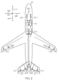
- FIG. 2 is a schematic depicting portions of an exemplary flight control surface actuation system according one embodiment of the present invention
- FIG. 3 is a functional block diagram of the flight control surface actuation system of FIG. 2, depicting certain portions thereof in slightly more detail;
- FIGS. 4 and 5 are simplified top and side view representations, respectively, of an exemplary user interface assembly that may be implemented as a flight control stick mechanism
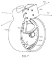
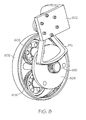
- FIGS. 6-8 are exemplary gear set configurations for a flight control stick mechanism.
- inventive user interface assembly is described herein as being implemented in an aircraft flight control system, it will be appreciated that it can be implemented in numerous other systems and environments in which it is desirable to supply haptic feedback to a user.
- the aircraft 100 includes first and second horizontal stabilizers 101-1 and 101-2, respectively, a vertical stabilizer 103, and first and second wings 105-1 and 105-2, respectively.
- An elevator 102 is disposed on each horizontal stabilizer 101-1, 101-2
- a rudder 104 is disposed on the vertical stabilizer 103
- an aileron 106 is disposed on each wing 105-1, 105-2.
- a plurality of flaps 108, slats 112, and spoilers 114 are disposed on each wing 105-1, 105-2.
- the elevators 102, the rudder 104, and the ailerons 106 are typically referred to as the primary flight control surfaces, and the flaps 108, the slats 112, and the spoilers 114 are typically referred to as the secondary flight control surfaces.
- the primary flight control surfaces 102-106 control aircraft movements about the aircraft pitch, yaw, and roll axes.
- the elevators 102 are used to control aircraft movement about the pitch axis
- the rudder 104 is used to control aircraft movement about the yaw axis
- the ailerons 106 control aircraft movement about the roll axis. It is noted, however, that aircraft movement about the yaw axis can also be achieved by varying the thrust levels from the engines on opposing sides of the aircraft 100. It will additionally be appreciated that the aircraft 100 could include horizontal stabilizers (not shown).
- the secondary control surfaces 108-114 influence the lift and drag of the aircraft 100.
- the flaps 108 and slats 112 may be moved from retracted positions to extended positions. In the extended position, the flaps 108 increase both lift and drag, and enable the aircraft 100 to descend more steeply for a given airspeed, and also enable the aircraft 100 get airborne over a shorter distance.
- the slats 112, in the extended position increase lift, and are typically used in conjunction with the flaps 108.
- the spoilers 114 reduce lift and when moved from retracted positions to extended positions, which is typically done during aircraft landing operations, may be used as air brakes to assist in slowing the aircraft 100.
- the flight control surfaces 102-114 are moved to commanded positions via a flight control surface actuation system 200, an exemplary embodiment of which is shown in FIG. 2.
- the flight control surface actuation system 200 includes one or more control units 202, a plurality of primary flight control surface actuators, which include elevator actuators 204, rudder actuators 206, and aileron actuators 208.
- the system 200 is preferably implemented with more than one control unit 202. However, for ease of description and illustration, only a single, multi-channel control unit 202 is depicted. It will additionally be appreciated that one or more functions of the control unit 202 could be implemented using a plurality of devices.
- the flight control surface actuation system 200 additionally includes a plurality of secondary control surface actuators, such as flap actuators, slat actuators, and spoiler actuators.
- secondary control surface actuators such as flap actuators, slat actuators, and spoiler actuators.
- the operation of the secondary flight control surfaces 108-114 and the associated actuators is not needed to fully describe and enable the present invention.
- the secondary flight control surfaces and actuators are not depicted in FIG. 2, nor are these devices further described.
- the flight control surface actuation system 200 may additionally be implemented using various numbers and types of primary flight control surface actuators 204-208.
- the number and type of primary flight control surface actuators 204-208 per primary flight control surface 102-106 may be varied. In the depicted embodiment, however, the system 200 is implemented such that two primary flight control surface actuators 204-208 are coupled to each primary flight control surface 102-106.
- each of the primary flight control surface actuators 204-208 are preferably a linear-type actuator, such as, for example, a ballscrew actuator. It will be appreciated that this number and type of primary flight control surface actuators 204-208 are merely exemplary of a particular embodiment, and that other numbers and types of actuators 204-208 could also be used.
- the control unit 202 is configured to receive aircraft flight control surface position commands from one or more input control mechanisms.
- the system 200 includes two user interfaces, a pilot user interface 210-1 and a co-pilot user interface 210-2, and one or more motor control units 212.
- the pilot 210-1 and co-pilot 210-2 user interfaces are both implemented as flight control sticks. It will be appreciated that in some embodiments, the system 200 could be implemented with more or less than this number of flight control sticks 210.
- the system could be implemented with more than one motor control unit 212, and that the flight control unit 202 and motor control unit 212 could be integrated into a single device. Nonetheless, the motor control unit 212, in response to position signals supplied from one or both flight control sticks 210, supplies flight control surface position signals to the flight control unit 202.
- the flight control unit 202 in response to the flight control surface position signals, supplies power to the appropriate primary flight control surface actuators 204, 208, to move the appropriate primary flight control surfaces 102, 106 to positions that will cause the aircraft 100 to implement the commanded maneuver.
- a separate non-depicted rudder pedal is included to control the rudder actuators 206, and thus the position of the rudder 104.
- FIG. 3 is also a functional block diagram of the flight control surface actuation system 200 depicting portions thereof in slightly more detail, the flight control sticks 210 are each configured to move, in response to input from either a pilot 302 or a co-pilot 304, to a control position in a displacement direction.
- the configuration of the flight control sticks 210 may vary, in the depicted embodiment, and with quick reference back to FIG.
- each flight control stick 210 is configured to be movable, from a null position 220, to a control position in a forward direction 222, an aft direction 224, a port direction 226, a starboard direction 228, a combined forward-port direction, a combined forward-starboard direction, a combined aft-port direction, or a combined aft-starboard direction, and back to or through the null position 220.
- flight control stick movement in the forward 222 or aft 224 direction causes the aircraft 100 to implement a downward or upward pitch maneuver, respectively
- flight control stick movement in the port 226 or starboard 228 direction causes the aircraft 100 to implement a port or starboard roll maneuver, respectively
- flight control stick movement in the combined forward-port or forward-starboard direction causes the aircraft 100 to implement, in combination, a downward pitch and either a port or a starboard roll maneuver, respectively
- flight control stick movement in the combined aft-port or aft-starboard direction causes the aircraft 100 to implement, in combination, an upward pitch and either a port or a starboard roll maneuver, respectively.
- the flight control sticks 210 are each configured to supply a control signal 306 to the motor control unit 212 that is representative of its position.
- a sensor 308 e.g., 308-1, 308-2
- the sensors 308 may be implemented using any one of numerous types of force and/or position sensors.
- the motor control unit 212 upon receipt of the control signals 306, supplies flight control surface position signals 312 to the flight control unit 202, which in turn supplies power to the appropriate primary flight control surface actuators 204, 208, to move the appropriate primary flight control surfaces 102, 106 to the appropriate positions, to thereby implement a desired maneuver.
- the motor control unit 212 may receive one or more force feedback influence signals 314 from the flight control unit 202, and supplies motor drive signals 316 to a pilot motor 318-1, a co-pilot motor 318-2, or both.
- the motors 318 which are each coupled to one of the flight control sticks 210 via associated gear sets 322 (e.g., 322-1, 322-2), are each operable, upon receipt of motor drive signals 316, to supply a feedback force to the associated flight control stick 210.
- the motor drive signals 316 may be variable in magnitude, based on the position of the flight control sticks 210, the slew rate of the flight control sticks 210, and various aircraft and control surface conditions, as represented by the one or more feedback influence signals 314.
- the motor drive signals 316 supplied to the pilot flight control stick 210-1 may also be variable in magnitude based on the position of the co-pilot flight control stick 210-2, and vice-versa.
- the flight control stick 210 in response to the feedback force supplied from the motor 318, supplies haptic feedback to the pilot 302 or co-pilot 304, as the case may be.
- current feedback signals 324 are supplied to the motor control unit 212.
- the motors 318 are implemented as brushless DC motors
- current feedback and commutation signals 324 are supplied to the motor control unit 212.
- the depicted flight control stick 210 is implemented with two motors, as mentioned above, and includes a user interface 402, a roll feedback motor 404, a roll feedback gear set 406, a pitch feedback gear housing 408, a pitch feedback motor 410, and an interface mechanism 412.
- the user interface 402 is coupled to the pitch feedback gear housing 408, which is mounted to rotate about a pitch axis 414 and a roll axis 416.
- the roll feedback motor 404 is coupled, via the roll feedback gear set 406, to the interface mechanism 412, which is in turn coupled to the pitch feedback gear housing 408.
- the roll feedback motor 404 is disposed such that its center of gravity (CG) is located at a first position 502 relative to the user interface 402 (see FIG. 5).
- the roll feedback motor 404 is coupled to receive motor drive signals, such as the above-described motor drive signals 316 that are supplied from the motor control unit 212, and supplies roll feedback to the user interface 402, via the roll feedback gear set 406, the interface mechanism 412, and the pitch feedback gear housing 406.
- the pitch feedback motor 410 is coupled to gears that are disposed within the pitch feedback gear housing 408.
- the pitch feedback motor 410 is also coupled to receive motor drive signals, such as the above-described motor drive signals 316 that are supplied from the motor control unit 212, and supplies feedback to the user interface 402, via a pitch feedback gear set that is disposed, at least partially, within the pitch feedback gear housing 408.
- the pitch feedback gear set is configured such that the pitch feedback motor 410 has a rotational axis that does not intersect that of the roll feedback motor 404, and such that the center of gravity (CG) of the pitch feedback motor 410 is located at a second position 504 relative to the user interface 402 (see FIG. 5).
- the first position 502 is located on the pitch axis 416, whereas the second position 504 is offset from the pitch axis center of rotation and is selected such that the user interface 402 is mass balanced when it is in the null position 220 (see FIG. 2).
- FIGS. 6-8 an exemplary embodiment of the pitch feedback gear set is depicted, and includes a ring gear 602, a sun gear 604, a plurality of planet gears 606, a planet carrier 608, a planet carrier gear 610, and a sector gear 612.
- the ring gear 602 is coupled to the pitch feedback gear housing 406.
- the sun gear 604 is coupled to, and receives the feedback force supplied by, the pitch feedback motor 410 (not shown in FIGS. 6-8).
- the planet gears 606 are rotationally mounted on the planet gear carrier 608 and each meshes with the ring gear 602 and the sun gear 604.
- the planet carrier gear 610 is coupled to the planet carrier 608, and meshes with the sector gear 612, which is in turn coupled to the interface mechanism 412.
- the pitch feedback motor 410 supplies a feedback force to the sun gear 604
- the feedback force is transferred to the user interface 402 via the planet carrier 608, the planet carrier gear 610, the sector gear 612, and the interface mechanism 412.
- the interface mechanism 614 is implemented using an L-bracket configuration, and is coupled between the roll feedback gear set 406 and the pitch feedback gear housing 408. More specifically, at least in the depicted embodiment, the interface mechanism 412 is coupled between the roll feedback gear set 406 and the sector gear 612. Thus, the interface mechanism 412 is mounted to about the pitch axis and to not rotate about the roll axis. It will be appreciated that the depicted L-bracket configuration is merely exemplary of a particular interface mechanism configuration, and that various other interface mechanism configurations could be used.
- FIGS. 4-7 and described above are useful for user interface assemblies that can rotate about at least two axes of rotation.
- other user interface assemblies may be configured to rotate only a single axis of rotation.
- the concepts described above for mass balancing multiple axis of rotation user interfaces can also be applied to user interfaces that only rotate about a single axis of rotation.
Abstract
Description
- This application claims the benefit of
U.S. Provisional Application No. 60/848,942, filed October 2, 2006 - The present invention relates to user interfaces and, more particularly, to a user interface assembly that includes one or more motors to provide haptic feedback and that is mass balanced by a haptic feedback motor.
- Aircraft typically include a plurality of flight control surfaces that, when controllably positioned, guide the movement of the aircraft from one destination to another. The number and type of flight control surfaces included in an aircraft may vary, but typically include both primary flight control surfaces and secondary flight control surfaces. The primary flight control surfaces are those that are used to control aircraft movement in the pitch, yaw, and roll axes, and the secondary flight control surfaces are those that are used to influence the lift or drag (or both) of the aircraft. Although some aircraft may include additional control surfaces, the primary flight control surfaces typically include a pair of elevators, a rudder, and a pair of ailerons, and the secondary flight control surfaces typically include a plurality of flaps, slats, and spoilers.
- The positions of the aircraft flight control surfaces are typically controlled using a flight control surface actuation system. The flight control surface actuation system, in response to position commands that originate from either the flight crew or an aircraft autopilot, moves the aircraft flight control surfaces to the commanded positions. In most instances, this movement is effected via actuators that are coupled to the flight control surfaces.
- Typically, the position commands that originate from the flight crew are supplied via some type of input control mechanism. For example, many aircraft include two yoke and wheel type of mechanisms, one for the pilot and one for the co-pilot. Either mechanism can be used to generate desired flight control surface position commands. More recently, however, aircraft are being implemented with control stick type mechanisms, which may be implemented as either side sticks or center sticks. Most notably in aircraft that employ a fly-by-wire system. Similar to the traditional yoke and wheel mechanisms, it is common to include multiple control stick mechanisms in the cockpit, one for the pilot and one for the co-pilot.
- Most control stick mechanisms are implemented with some type of mass balance, such as counterbalance weights, to alleviate a potentially large moment that may exist when an aircraft experiences accelerations resulting from longitudinal and lateral accelerations. These additional counterbalance weights can be undesirable in some instances. For example, the counterbalance weights, when included, are in addition to the mounting, control, and feedback hardware associated with the control stick mechanism. Thus, overall size envelope and weight may increase, which may result in a concomitant increase in costs.
- Hence, there is a need for a flight control stick mechanism that is mass balanced, but does not increase, or at least significantly increase, overall control stick size and/or weight. The present invention addresses at least this need.
- In one embodiment, and by way of example only, an active user interface assembly includes a housing, a user interface, and a feedback motor. The user interface is coupled to and extends from the housing, and is rotatable, from a null position, about an axis. The feedback motor is coupled to the user interface and is adapted to be selectively energized. The feedback motor is operable, upon being energized, to supply a feedback force to the user interface that opposes user interface movement about the axis. The feedback motor is disposed such that its center of gravity is located at a position relative to the user interface to mass balance the user interface when it is in the null position.
- In another exemplary embodiment, an active user interface assembly includes a housing, a user interface, a first feedback motor, and a second feedback motor. The user interface is coupled to and extends from the housing, and is rotatable, from a null position, about a first axis and a second axis. The first and second axes are perpendicular. The first feedback motor is coupled to the user interface and is disposed such that its center of gravity is located at a first position relative to the user interface. The first feedback motor is adapted to be selectively energized and is operable, upon being energized, to supply a feedback force to the user interface that opposes user interface movement about the first axis. The second feedback motor is coupled to the user interface and is disposed such that its center of gravity is located at a second position relative to the user interface. The second feedback motor is adapted to be selectively energized and is operable, upon being energized, to supply a feedback force to the user interface that opposes user interface movement about the second axis. At least one of the first position and the second position are selected to mass balance the user interface when it is in the null position.
- Other independent features and advantages of the preferred user interface assembly will become apparent from the following detailed description, taken in conjunction with the accompanying drawings which illustrate, by way of example, the principles of the invention.
- FIG. 1 is a perspective view of an exemplary aircraft depicting primary and secondary flight control surfaces;
- FIG. 2 is a schematic depicting portions of an exemplary flight control surface actuation system according one embodiment of the present invention;
- FIG. 3 is a functional block diagram of the flight control surface actuation system of FIG. 2, depicting certain portions thereof in slightly more detail;
- FIGS. 4 and 5 are simplified top and side view representations, respectively, of an exemplary user interface assembly that may be implemented as a flight control stick mechanism; and
- FIGS. 6-8 are exemplary gear set configurations for a flight control stick mechanism.
- The following detailed description is merely exemplary in nature and is not intended to limit the invention or the application and uses of the invention. Furthermore, there is no intention to be bound by any theory presented in the preceding background or the following detailed description. In this regard, although the inventive user interface assembly is described herein as being implemented in an aircraft flight control system, it will be appreciated that it can be implemented in numerous other systems and environments in which it is desirable to supply haptic feedback to a user.
- Turning now to FIG. 1, a perspective view of an exemplary aircraft is shown. In the illustrated embodiment, the
aircraft 100 includes first and second horizontal stabilizers 101-1 and 101-2, respectively, avertical stabilizer 103, and first and second wings 105-1 and 105-2, respectively. Anelevator 102 is disposed on each horizontal stabilizer 101-1, 101-2, arudder 104 is disposed on thevertical stabilizer 103, and anaileron 106 is disposed on each wing 105-1, 105-2. In addition, a plurality offlaps 108,slats 112, andspoilers 114 are disposed on each wing 105-1, 105-2. Theelevators 102, therudder 104, and theailerons 106 are typically referred to as the primary flight control surfaces, and theflaps 108, theslats 112, and thespoilers 114 are typically referred to as the secondary flight control surfaces. - The primary flight control surfaces 102-106 control aircraft movements about the aircraft pitch, yaw, and roll axes. Specifically, the
elevators 102 are used to control aircraft movement about the pitch axis, therudder 104 is used to control aircraft movement about the yaw axis, and theailerons 106 control aircraft movement about the roll axis. It is noted, however, that aircraft movement about the yaw axis can also be achieved by varying the thrust levels from the engines on opposing sides of theaircraft 100. It will additionally be appreciated that theaircraft 100 could include horizontal stabilizers (not shown). - The secondary control surfaces 108-114 influence the lift and drag of the
aircraft 100. For example, during aircraft take-off and landing operations, when increased lift is desirable, theflaps 108 andslats 112 may be moved from retracted positions to extended positions. In the extended position, theflaps 108 increase both lift and drag, and enable theaircraft 100 to descend more steeply for a given airspeed, and also enable theaircraft 100 get airborne over a shorter distance. Theslats 112, in the extended position, increase lift, and are typically used in conjunction with theflaps 108. Thespoilers 114, on the other hand, reduce lift and when moved from retracted positions to extended positions, which is typically done during aircraft landing operations, may be used as air brakes to assist in slowing theaircraft 100. - The flight control surfaces 102-114 are moved to commanded positions via a flight control
surface actuation system 200, an exemplary embodiment of which is shown in FIG. 2. In the depicted embodiment, the flight controlsurface actuation system 200 includes one ormore control units 202, a plurality of primary flight control surface actuators, which includeelevator actuators 204,rudder actuators 206, andaileron actuators 208. It will be appreciated that thesystem 200 is preferably implemented with more than onecontrol unit 202. However, for ease of description and illustration, only a single,multi-channel control unit 202 is depicted. It will additionally be appreciated that one or more functions of thecontrol unit 202 could be implemented using a plurality of devices. - Before proceeding further, it is noted that the flight control
surface actuation system 200 additionally includes a plurality of secondary control surface actuators, such as flap actuators, slat actuators, and spoiler actuators. However, the operation of the secondary flight control surfaces 108-114 and the associated actuators is not needed to fully describe and enable the present invention. Thus, for added clarity, ease of description, and ease of illustration, the secondary flight control surfaces and actuators are not depicted in FIG. 2, nor are these devices further described. - Returning now to the description, the flight control
surface actuation system 200 may additionally be implemented using various numbers and types of primary flight control surface actuators 204-208. In addition, the number and type of primary flight control surface actuators 204-208 per primary flight control surface 102-106 may be varied. In the depicted embodiment, however, thesystem 200 is implemented such that two primary flight control surface actuators 204-208 are coupled to each primary flight control surface 102-106. Moreover, each of the primary flight control surface actuators 204-208 are preferably a linear-type actuator, such as, for example, a ballscrew actuator. It will be appreciated that this number and type of primary flight control surface actuators 204-208 are merely exemplary of a particular embodiment, and that other numbers and types of actuators 204-208 could also be used. - No matter the specific number, configuration, and implementation of the
control units 202 and the primary flight control surface actuators 204-208, thecontrol unit 202 is configured to receive aircraft flight control surface position commands from one or more input control mechanisms. In the depicted embodiment, thesystem 200 includes two user interfaces, a pilot user interface 210-1 and a co-pilot user interface 210-2, and one or moremotor control units 212. As will be described in more detail below, the pilot 210-1 and co-pilot 210-2 user interfaces are both implemented as flight control sticks. It will be appreciated that in some embodiments, thesystem 200 could be implemented with more or less than this number of flight control sticks 210. It will additionally be appreciated that the system could be implemented with more than onemotor control unit 212, and that theflight control unit 202 andmotor control unit 212 could be integrated into a single device. Nonetheless, themotor control unit 212, in response to position signals supplied from one or both flight control sticks 210, supplies flight control surface position signals to theflight control unit 202. Theflight control unit 202, in response to the flight control surface position signals, supplies power to the appropriate primary flightcontrol surface actuators flight control surfaces aircraft 100 to implement the commanded maneuver. Preferably, though not necessarily, a separate non-depicted rudder pedal is included to control therudder actuators 206, and thus the position of therudder 104. - Turning now to FIG. 3, which is also a functional block diagram of the flight control
surface actuation system 200 depicting portions thereof in slightly more detail, the flight control sticks 210 are each configured to move, in response to input from either apilot 302 or aco-pilot 304, to a control position in a displacement direction. Although the configuration of the flight control sticks 210 may vary, in the depicted embodiment, and with quick reference back to FIG. 2, each flight control stick 210 is configured to be movable, from anull position 220, to a control position in aforward direction 222, anaft direction 224, aport direction 226, astarboard direction 228, a combined forward-port direction, a combined forward-starboard direction, a combined aft-port direction, or a combined aft-starboard direction, and back to or through thenull position 220. It will be appreciated that flight control stick movement in the forward 222 or aft 224 direction causes theaircraft 100 to implement a downward or upward pitch maneuver, respectively, flight control stick movement in theport 226 or starboard 228 direction causes theaircraft 100 to implement a port or starboard roll maneuver, respectively, flight control stick movement in the combined forward-port or forward-starboard direction, causes theaircraft 100 to implement, in combination, a downward pitch and either a port or a starboard roll maneuver, respectively, and flight control stick movement in the combined aft-port or aft-starboard direction, causes theaircraft 100 to implement, in combination, an upward pitch and either a port or a starboard roll maneuver, respectively. - Returning once again to FIG. 3, the flight control sticks 210 are each configured to supply a
control signal 306 to themotor control unit 212 that is representative of its position. To do so, a sensor 308 (e.g., 308-1, 308-2) is coupled to each flight control stick 210. The sensors 308 may be implemented using any one of numerous types of force and/or position sensors. Themotor control unit 212, upon receipt of the control signals 306, supplies flight control surface position signals 312 to theflight control unit 202, which in turn supplies power to the appropriate primary flightcontrol surface actuators flight control surfaces motor control unit 212 may receive one or more force feedback influence signals 314 from theflight control unit 202, and supplies motor drive signals 316 to a pilot motor 318-1, a co-pilot motor 318-2, or both. - The motors 318, which are each coupled to one of the flight control sticks 210 via associated gear sets 322 (e.g., 322-1, 322-2), are each operable, upon receipt of motor drive signals 316, to supply a feedback force to the associated flight control stick 210. It will be appreciated that, at least in some embodiments, the motor drive signals 316 may be variable in magnitude, based on the position of the flight control sticks 210, the slew rate of the flight control sticks 210, and various aircraft and control surface conditions, as represented by the one or more feedback influence signals 314. The motor drive signals 316 supplied to the pilot flight control stick 210-1 may also be variable in magnitude based on the position of the co-pilot flight control stick 210-2, and vice-versa. The flight control stick 210, in response to the feedback force supplied from the motor 318, supplies haptic feedback to the
pilot 302 orco-pilot 304, as the case may be. Preferably, current feedback signals 324 are supplied to themotor control unit 212. Moreover, in a particular preferred embodiment, in which the motors 318 are implemented as brushless DC motors, current feedback and commutation signals 324 are supplied to themotor control unit 212. - Before proceeding further, it is noted that only a single pilot motor 318-1 and gear set 322-1 and a single co-pilot motor 318-2 and gear set 322-2 are shown in FIG. 3. It will be appreciated that this is done merely for clarity and ease of depiction and description, and that the
system 200 would likely be implemented with two pilot motors 318-1 and gear sets 322-1 and two co-pilot motors 318-2 and gear sets 322-2. With two motors 318 and gear sets 322 associated with each flight control stick 210, feedback force can be supplied along two orthogonal axes. - Returning to the description and with reference now to FIGS. 4 and 5, a simplified representation of a user interface assembly that may be used to implement one of the flight control sticks 210 is depicted. The depicted flight control stick 210 is implemented with two motors, as mentioned above, and includes a
user interface 402, aroll feedback motor 404, a roll feedback gear set 406, a pitchfeedback gear housing 408, apitch feedback motor 410, and aninterface mechanism 412. Theuser interface 402 is coupled to the pitchfeedback gear housing 408, which is mounted to rotate about apitch axis 414 and aroll axis 416. Theroll feedback motor 404 is coupled, via the roll feedback gear set 406, to theinterface mechanism 412, which is in turn coupled to the pitchfeedback gear housing 408. Theroll feedback motor 404 is disposed such that its center of gravity (CG) is located at afirst position 502 relative to the user interface 402 (see FIG. 5). Theroll feedback motor 404 is coupled to receive motor drive signals, such as the above-described motor drive signals 316 that are supplied from themotor control unit 212, and supplies roll feedback to theuser interface 402, via the roll feedback gear set 406, theinterface mechanism 412, and the pitchfeedback gear housing 406. - The
pitch feedback motor 410 is coupled to gears that are disposed within the pitchfeedback gear housing 408. Thepitch feedback motor 410 is also coupled to receive motor drive signals, such as the above-described motor drive signals 316 that are supplied from themotor control unit 212, and supplies feedback to theuser interface 402, via a pitch feedback gear set that is disposed, at least partially, within the pitchfeedback gear housing 408. The pitch feedback gear set is configured such that thepitch feedback motor 410 has a rotational axis that does not intersect that of theroll feedback motor 404, and such that the center of gravity (CG) of thepitch feedback motor 410 is located at asecond position 504 relative to the user interface 402 (see FIG. 5). Preferably, thefirst position 502 is located on thepitch axis 416, whereas thesecond position 504 is offset from the pitch axis center of rotation and is selected such that theuser interface 402 is mass balanced when it is in the null position 220 (see FIG. 2). - Turning now to FIGS. 6-8, an exemplary embodiment of the pitch feedback gear set is depicted, and includes a
ring gear 602, asun gear 604, a plurality of planet gears 606, aplanet carrier 608, aplanet carrier gear 610, and asector gear 612. Thering gear 602 is coupled to the pitchfeedback gear housing 406. Thesun gear 604 is coupled to, and receives the feedback force supplied by, the pitch feedback motor 410 (not shown in FIGS. 6-8). The planet gears 606 are rotationally mounted on theplanet gear carrier 608 and each meshes with thering gear 602 and thesun gear 604. Theplanet carrier gear 610 is coupled to theplanet carrier 608, and meshes with thesector gear 612, which is in turn coupled to theinterface mechanism 412. Thus, when thepitch feedback motor 410 supplies a feedback force to thesun gear 604, the feedback force is transferred to theuser interface 402 via theplanet carrier 608, theplanet carrier gear 610, thesector gear 612, and theinterface mechanism 412. - The interface mechanism 614, at least in the depicted embodiment, is implemented using an L-bracket configuration, and is coupled between the roll feedback gear set 406 and the pitch
feedback gear housing 408. More specifically, at least in the depicted embodiment, theinterface mechanism 412 is coupled between the roll feedback gear set 406 and thesector gear 612. Thus, theinterface mechanism 412 is mounted to about the pitch axis and to not rotate about the roll axis. It will be appreciated that the depicted L-bracket configuration is merely exemplary of a particular interface mechanism configuration, and that various other interface mechanism configurations could be used. - The configurations depicted in FIGS. 4-7 and described above are useful for user interface assemblies that can rotate about at least two axes of rotation. However, other user interface assemblies may be configured to rotate only a single axis of rotation. It will be appreciated that the concepts described above for mass balancing multiple axis of rotation user interfaces can also be applied to user interfaces that only rotate about a single axis of rotation.
- The configurations depicted and described herein allow for the center of gravity of a feedback motor to be positioned in a manner that alleviates the need for counterbalance weights.
- While the invention has been described with reference to a preferred embodiment, it will be understood by those skilled in the art that various changes may be made and equivalents may be substituted for elements thereof without departing from the scope of the invention. In addition, many modifications may be made to adapt to a particular situation or material to the teachings of the invention without departing from the essential scope thereof.
Claims (10)
- An active user interface assembly, comprising:a housing (408);a user interface (402) coupled to and extending from the housing, the user interface (402) rotatable, from a null position, about an axis; anda feedback motor (404, 410) coupled to the user interface and adapted to be selectively energized, the feedback motor operable, upon being energized, to supply a feedback force to the user interface that opposes user interface movement about the axis, the feedback motor disposed such that its center of gravity is located at a position relative to the user interface to mass balance the user interface when it is in the null position.
- The assembly of Claim 1, further comprising:a feedback gear set coupled between the feedback motor and the user interface.
- The assembly of Claim 2, wherein the feedback gear set is disposed at least partially within the housing.
- The assembly of Claim 2, wherein the feedback gear set comprises:a ring gear (602) coupled to the housing;a plurality of planet gears (606), each planet gear meshed with the ring gear (602);a sun gear (604) meshed with each of the planet gears (606) and coupled to the feedback motor.
- The assembly of Claim 4, further comprising:a planet carrier (608) having each of the planet gears (606) rotationally disposed thereon;a carrier gear coupled to the planet carrier (608); anda sector gear (612) meshed with the carrier gear and coupled to the user interface (402).
- The assembly of Claim 5, wherein the sector gear (612) is coupled to the user interface (402) via the housing.
- An active user interface assembly, comprising:a housing (408);a user interface (402) coupled to and extending from the housing, the user interface rotatable, from a null position, about a first axis and a second axis, the first and second axes being perpendicular;a first feedback motor (404) coupled to the user interface and disposed such that its center of gravity is located at a first position (502) relative to the user interface (402), the first feedback motor adapted to be selectively energized and operable, upon being energized, to supply a feedback force to the user interface that opposes user interface movement about the first axis;a second feedback motor (410) coupled to the user interface and disposed such that its center of gravity is located at a second position (504) relative to the user interface, the second feedback motor adapted to be selectively energized and operable, upon being energized, to supply a feedback force to the user interface that opposes user interface movement about the second axis,wherein at least one of the first position and the second position are selected to mass balance the user interface when it is in the null position.
- The assembly of Claim 7, further comprising:a first feedback gear set coupled between the first feedback motor (404) and the user interface.
- The assembly of Claim 8, further comprising:a second feedback gear set (406) coupled between the second feedback motor (410) and the user interface.
- The assembly of Claim 9, further comprising:an interface mechanism (412) coupled between the second feedback gear set and the user interface.
Applications Claiming Priority (2)
| Application Number | Priority Date | Filing Date | Title |
|---|---|---|---|
| US84894206P | 2006-10-02 | 2006-10-02 | |
| US11/676,845 US7701161B2 (en) | 2006-10-02 | 2007-02-20 | Motor balanced active user interface assembly |
Publications (3)
| Publication Number | Publication Date |
|---|---|
| EP1908685A2 true EP1908685A2 (en) | 2008-04-09 |
| EP1908685A3 EP1908685A3 (en) | 2012-12-12 |
| EP1908685B1 EP1908685B1 (en) | 2014-04-09 |
Family
ID=38860078
Family Applications (1)
| Application Number | Title | Priority Date | Filing Date |
|---|---|---|---|
| EP07117684.6A Expired - Fee Related EP1908685B1 (en) | 2006-10-02 | 2007-10-01 | Motor balanced active user interface assembly |
Country Status (2)
| Country | Link |
|---|---|
| US (1) | US7701161B2 (en) |
| EP (1) | EP1908685B1 (en) |
Cited By (4)
| Publication number | Priority date | Publication date | Assignee | Title |
|---|---|---|---|---|
| EP2112063A2 (en) | 2008-04-23 | 2009-10-28 | Honeywell International Inc. | Active pilot inceptor with self warm-up |
| GB2516248A (en) * | 2012-11-16 | 2015-01-21 | Norman L Mcculloch | Improvements in aircraft |
| EP2586702A3 (en) * | 2011-10-28 | 2018-04-18 | Woodward MPC, Inc. | Compact two axis gimbal for control stick |
| WO2022194849A1 (en) * | 2021-03-16 | 2022-09-22 | Inventus Engineering Gmbh | Control device comprising at least one pivotable control lever |
Families Citing this family (12)
| Publication number | Priority date | Publication date | Assignee | Title |
|---|---|---|---|---|
| WO2008122820A2 (en) * | 2007-04-05 | 2008-10-16 | Bombardier Inc. | Multi-axis serially redundant, single channel, multi-path fly-by-wire flight control system |
| GB0714916D0 (en) | 2007-07-31 | 2007-09-12 | Wittenstein Aerospace & Simula | Control device |
| CN103782502B (en) * | 2011-07-26 | 2017-11-17 | 莫戈公司 | motor clamping system |
| EP2597034B1 (en) | 2011-11-28 | 2015-11-04 | AIRBUS HELICOPTERS DEUTSCHLAND GmbH | Counterbalanced control stick system |
| US10759515B2 (en) | 2014-09-10 | 2020-09-01 | Hamilton Sunstrand Corporation | Electromechanical hinge-line rotary actuator |
| US20160229525A1 (en) * | 2014-09-10 | 2016-08-11 | Hamilton Sundstrand Corporation | Electromechanical rotary actuator |
| FR3031959B1 (en) * | 2015-01-27 | 2017-02-17 | Ratier Figeac Soc | METHOD AND DEVICE FOR CONJUGATING CONTROL RODS |
| US10118688B2 (en) * | 2015-08-18 | 2018-11-06 | Woodward, Inc. | Inherently balanced control stick |
| US10005561B2 (en) | 2016-06-16 | 2018-06-26 | Ge Aviation Systems Llc | Controlling aircraft using thrust differential trim |
| US9823686B1 (en) * | 2016-08-15 | 2017-11-21 | Clause Technology | Three-axis motion joystick |
| US9889874B1 (en) * | 2016-08-15 | 2018-02-13 | Clause Technology | Three-axis motion joystick |
| AT520763B1 (en) * | 2017-12-21 | 2022-09-15 | Hans Kuenz Gmbh | crane control |
Citations (6)
| Publication number | Priority date | Publication date | Assignee | Title |
|---|---|---|---|---|
| US5125602A (en) | 1989-02-20 | 1992-06-30 | Aerospatiale Societe Nationale Industrielle | Tilting stick control device, especially for an aircraft, and system comprising two such devices |
| US5898599A (en) | 1993-10-01 | 1999-04-27 | Massachusetts Institute Of Technology | Force reflecting haptic interface |
| US6429849B1 (en) | 2000-02-29 | 2002-08-06 | Microsoft Corporation | Haptic feedback joystick |
| US6708580B1 (en) | 1999-06-11 | 2004-03-23 | Wittenstein Gmbh & Co. Kg | Device for controlling an apparatus |
| EP1480238A2 (en) | 2003-05-19 | 2004-11-24 | Alps Electric Co., Ltd. | Force feedback input device |
| EP1598724A2 (en) | 2004-05-19 | 2005-11-23 | Alps Electric Co., Ltd. | Haptic feedback input device |
Family Cites Families (17)
| Publication number | Priority date | Publication date | Assignee | Title |
|---|---|---|---|---|
| US2475484A (en) | 1946-05-14 | 1949-07-05 | Nise Dwight Dee De | Method and means for imparting feel back to a manually-movable control element |
| US2678179A (en) | 1949-01-24 | 1954-05-11 | Northrop Aircraft Inc | Hydraulic trim control |
| US2955784A (en) | 1956-02-27 | 1960-10-11 | Northrop Corp | Servo regulated elevator feel system |
| US4071209A (en) | 1976-08-23 | 1978-01-31 | Lockheed Corporation | Vehicle control system incorporating a compensator to stabilize the inherent dynamics thereof |
| US4069720A (en) | 1976-11-05 | 1978-01-24 | Thor Wayne A | Two axis side controller for aircraft |
| US4150803A (en) | 1977-10-05 | 1979-04-24 | Fernandez Carlos P | Two axes controller |
| US4383455A (en) | 1980-10-21 | 1983-05-17 | Kobe Steel, Limited | Arm with gravity-balancing function |
| DE3380420D1 (en) | 1982-01-22 | 1989-09-21 | British Aerospace | Control apparatus |
| GB8801951D0 (en) | 1988-01-29 | 1988-02-24 | British Aerospace | Control apparatus |
| US5107080A (en) | 1989-12-01 | 1992-04-21 | Massachusetts Institute Of Technology | Multiple degree of freedom damped hand controls |
| US6437771B1 (en) | 1995-01-18 | 2002-08-20 | Immersion Corporation | Force feedback device including flexure member between actuator and user object |
| US5456428A (en) | 1993-07-21 | 1995-10-10 | Honeywell Inc. | Mechanically linked active sidesticks |
| US5473235A (en) * | 1993-12-21 | 1995-12-05 | Honeywell Inc. | Moment cell counterbalance for active hand controller |
| JP2716661B2 (en) | 1994-08-23 | 1998-02-18 | 川崎重工業株式会社 | Operation device |
| US6459228B1 (en) * | 2001-03-22 | 2002-10-01 | Mpc Products Corporation | Dual input servo coupled control sticks |
| US6644600B1 (en) | 2002-04-25 | 2003-11-11 | Rockwell Collins, Inc. | Method and system for providing manipulation restraining forces for a stick controller on an aircraft |
| DE10305261A1 (en) | 2003-02-07 | 2004-08-26 | Wittenstein Ag | Device for controlling a vehicle |
-
2007
- 2007-02-20 US US11/676,845 patent/US7701161B2/en not_active Expired - Fee Related
- 2007-10-01 EP EP07117684.6A patent/EP1908685B1/en not_active Expired - Fee Related
Patent Citations (6)
| Publication number | Priority date | Publication date | Assignee | Title |
|---|---|---|---|---|
| US5125602A (en) | 1989-02-20 | 1992-06-30 | Aerospatiale Societe Nationale Industrielle | Tilting stick control device, especially for an aircraft, and system comprising two such devices |
| US5898599A (en) | 1993-10-01 | 1999-04-27 | Massachusetts Institute Of Technology | Force reflecting haptic interface |
| US6708580B1 (en) | 1999-06-11 | 2004-03-23 | Wittenstein Gmbh & Co. Kg | Device for controlling an apparatus |
| US6429849B1 (en) | 2000-02-29 | 2002-08-06 | Microsoft Corporation | Haptic feedback joystick |
| EP1480238A2 (en) | 2003-05-19 | 2004-11-24 | Alps Electric Co., Ltd. | Force feedback input device |
| EP1598724A2 (en) | 2004-05-19 | 2005-11-23 | Alps Electric Co., Ltd. | Haptic feedback input device |
Cited By (8)
| Publication number | Priority date | Publication date | Assignee | Title |
|---|---|---|---|---|
| EP2112063A2 (en) | 2008-04-23 | 2009-10-28 | Honeywell International Inc. | Active pilot inceptor with self warm-up |
| EP2112063A3 (en) * | 2008-04-23 | 2013-01-09 | Honeywell International Inc. | Active pilot inceptor with self warm-up |
| EP2586702A3 (en) * | 2011-10-28 | 2018-04-18 | Woodward MPC, Inc. | Compact two axis gimbal for control stick |
| EP3388334A1 (en) * | 2011-10-28 | 2018-10-17 | Woodward MPC, Inc. | Compact two axis gimbal for control stick |
| GB2516248A (en) * | 2012-11-16 | 2015-01-21 | Norman L Mcculloch | Improvements in aircraft |
| GB2521814A (en) * | 2012-11-16 | 2015-07-08 | Norman L Mcculloch | Improvements in aircraft |
| GB2521814B (en) * | 2012-11-16 | 2018-11-14 | L Mcculloch Norman | A feedback system for a flying control member of an aircraft |
| WO2022194849A1 (en) * | 2021-03-16 | 2022-09-22 | Inventus Engineering Gmbh | Control device comprising at least one pivotable control lever |
Also Published As
| Publication number | Publication date |
|---|---|
| US20080079381A1 (en) | 2008-04-03 |
| EP1908685A3 (en) | 2012-12-12 |
| US7701161B2 (en) | 2010-04-20 |
| EP1908685B1 (en) | 2014-04-09 |
Similar Documents
| Publication | Publication Date | Title |
|---|---|---|
| EP1908685B1 (en) | Motor balanced active user interface assembly | |
| EP1918196B1 (en) | Pilot flight control stick haptic feedback system and method | |
| EP2076432B1 (en) | Cogless motor driven active user interface haptic feedback system | |
| US20070235594A1 (en) | Pilot flight control stick feedback system | |
| US7549605B2 (en) | Electric flight control surface actuation system for aircraft flaps and slats | |
| EP2058227B1 (en) | Active user interface haptic feedback and linking control system using either force or position data | |
| US8080966B2 (en) | Motor control architecture for simultaneously controlling multiple motors | |
| EP1989105B1 (en) | Full authority fly-by-wire pedal system | |
| EP1803644B1 (en) | Distributed flight control surface actuation system | |
| US7770842B2 (en) | Aircraft flight control surface actuation system communication architecture | |
| KR101323836B1 (en) | Emergency piloting by means of a series actuator for a manual flight control system in an aircraft | |
| US8240617B2 (en) | Variable damping of haptic feedback for a flight-attitude changing linkage of an aircraft | |
| US20080156939A1 (en) | Active pilot flight control stick system with passive electromagnetic feedback | |
| EP2052966B1 (en) | Rate limited active pilot inceptor system and method | |
| EP1873057B1 (en) | Active rudder pedal mechanism with foreign object strike tolerance and articulating brake | |
| US8401716B2 (en) | Flight control systems | |
| EP1977970A2 (en) | User interface passive haptic feedback system | |
| EP2078997A2 (en) | Human-machine interface with variable null breakout force | |
| EP1781538B1 (en) | Aircraft flight control surface actuation system communication architecture | |
| WO2024076800A2 (en) | Systems, methods, and devices for operation of a vehicle |
Legal Events
| Date | Code | Title | Description |
|---|---|---|---|
| PUAI | Public reference made under article 153(3) epc to a published international application that has entered the european phase |
Free format text: ORIGINAL CODE: 0009012 |
|
| 17P | Request for examination filed |
Effective date: 20071001 |
|
| AK | Designated contracting states |
Kind code of ref document: A2 Designated state(s): AT BE BG CH CY CZ DE DK EE ES FI FR GB GR HU IE IS IT LI LT LU LV MC MT NL PL PT RO SE SI SK TR |
|
| AX | Request for extension of the european patent |
Extension state: AL BA HR MK RS |
|
| RIN1 | Information on inventor provided before grant (corrected) |
Inventor name: SMITH, DOUGLAS C. Inventor name: HANLON, CASEY Inventor name: KERN, JAMES I. |
|
| PUAL | Search report despatched |
Free format text: ORIGINAL CODE: 0009013 |
|
| RIC1 | Information provided on ipc code assigned before grant |
Ipc: G05G 5/03 20080401ALI20121026BHEP Ipc: B64C 13/46 20060101ALI20121026BHEP Ipc: B64C 13/04 20060101AFI20121026BHEP |
|
| AK | Designated contracting states |
Kind code of ref document: A3 Designated state(s): AT BE BG CH CY CZ DE DK EE ES FI FR GB GR HU IE IS IT LI LT LU LV MC MT NL PL PT RO SE SI SK TR |
|
| AX | Request for extension of the european patent |
Extension state: AL BA HR MK RS |
|
| 17Q | First examination report despatched |
Effective date: 20121123 |
|
| AKX | Designation fees paid |
Designated state(s): DE FR GB |
|
| GRAP | Despatch of communication of intention to grant a patent |
Free format text: ORIGINAL CODE: EPIDOSNIGR1 |
|
| RIC1 | Information provided on ipc code assigned before grant |
Ipc: B64C 13/46 20060101ALI20131029BHEP Ipc: B64C 13/04 20060101AFI20131029BHEP Ipc: G05G 9/047 20060101ALI20131029BHEP Ipc: G05G 5/03 20080401ALI20131029BHEP |
|
| INTG | Intention to grant announced |
Effective date: 20131125 |
|
| GRAS | Grant fee paid |
Free format text: ORIGINAL CODE: EPIDOSNIGR3 |
|
| GRAA | (expected) grant |
Free format text: ORIGINAL CODE: 0009210 |
|
| AK | Designated contracting states |
Kind code of ref document: B1 Designated state(s): DE FR GB |
|
| REG | Reference to a national code |
Ref country code: GB Ref legal event code: FG4D |
|
| REG | Reference to a national code |
Ref country code: DE Ref legal event code: R096 Ref document number: 602007035996 Country of ref document: DE Effective date: 20140522 |
|
| REG | Reference to a national code |
Ref country code: DE Ref legal event code: R097 Ref document number: 602007035996 Country of ref document: DE |
|
| PLBE | No opposition filed within time limit |
Free format text: ORIGINAL CODE: 0009261 |
|
| STAA | Information on the status of an ep patent application or granted ep patent |
Free format text: STATUS: NO OPPOSITION FILED WITHIN TIME LIMIT |
|
| 26N | No opposition filed |
Effective date: 20150112 |
|
| REG | Reference to a national code |
Ref country code: DE Ref legal event code: R097 Ref document number: 602007035996 Country of ref document: DE Effective date: 20150112 |
|
| REG | Reference to a national code |
Ref country code: FR Ref legal event code: PLFP Year of fee payment: 9 |
|
| PGFP | Annual fee paid to national office [announced via postgrant information from national office to epo] |
Ref country code: GB Payment date: 20150924 Year of fee payment: 9 |
|
| PGFP | Annual fee paid to national office [announced via postgrant information from national office to epo] |
Ref country code: FR Payment date: 20150924 Year of fee payment: 9 |
|
| PGFP | Annual fee paid to national office [announced via postgrant information from national office to epo] |
Ref country code: DE Payment date: 20151030 Year of fee payment: 9 |
|
| REG | Reference to a national code |
Ref country code: DE Ref legal event code: R119 Ref document number: 602007035996 Country of ref document: DE |
|
| GBPC | Gb: european patent ceased through non-payment of renewal fee |
Effective date: 20161001 |
|
| REG | Reference to a national code |
Ref country code: FR Ref legal event code: ST Effective date: 20170630 |
|
| PG25 | Lapsed in a contracting state [announced via postgrant information from national office to epo] |
Ref country code: DE Free format text: LAPSE BECAUSE OF NON-PAYMENT OF DUE FEES Effective date: 20170503 Ref country code: FR Free format text: LAPSE BECAUSE OF NON-PAYMENT OF DUE FEES Effective date: 20161102 Ref country code: GB Free format text: LAPSE BECAUSE OF NON-PAYMENT OF DUE FEES Effective date: 20161001 |
|
| P01 | Opt-out of the competence of the unified patent court (upc) registered |
Effective date: 20230525 |