EP1906471A1 - A battery separator for extending the cycle life of a battery - Google Patents
A battery separator for extending the cycle life of a battery Download PDFInfo
- Publication number
- EP1906471A1 EP1906471A1 EP07018273A EP07018273A EP1906471A1 EP 1906471 A1 EP1906471 A1 EP 1906471A1 EP 07018273 A EP07018273 A EP 07018273A EP 07018273 A EP07018273 A EP 07018273A EP 1906471 A1 EP1906471 A1 EP 1906471A1
- Authority
- EP
- European Patent Office
- Prior art keywords
- battery
- conductive layer
- separator
- battery separator
- positive electrode
- Prior art date
- Legal status (The legal status is an assumption and is not a legal conclusion. Google has not performed a legal analysis and makes no representation as to the accuracy of the status listed.)
- Granted
Links
Images


Classifications
-
- H—ELECTRICITY
- H01—ELECTRIC ELEMENTS
- H01M—PROCESSES OR MEANS, e.g. BATTERIES, FOR THE DIRECT CONVERSION OF CHEMICAL ENERGY INTO ELECTRICAL ENERGY
- H01M10/00—Secondary cells; Manufacture thereof
- H01M10/06—Lead-acid accumulators
- H01M10/12—Construction or manufacture
-
- H—ELECTRICITY
- H01—ELECTRIC ELEMENTS
- H01M—PROCESSES OR MEANS, e.g. BATTERIES, FOR THE DIRECT CONVERSION OF CHEMICAL ENERGY INTO ELECTRICAL ENERGY
- H01M50/00—Constructional details or processes of manufacture of the non-active parts of electrochemical cells other than fuel cells, e.g. hybrid cells
- H01M50/40—Separators; Membranes; Diaphragms; Spacing elements inside cells
- H01M50/403—Manufacturing processes of separators, membranes or diaphragms
-
- B—PERFORMING OPERATIONS; TRANSPORTING
- B32—LAYERED PRODUCTS
- B32B—LAYERED PRODUCTS, i.e. PRODUCTS BUILT-UP OF STRATA OF FLAT OR NON-FLAT, e.g. CELLULAR OR HONEYCOMB, FORM
- B32B3/00—Layered products comprising a layer with external or internal discontinuities or unevennesses, or a layer of non-planar form; Layered products having particular features of form
- B32B3/26—Layered products comprising a layer with external or internal discontinuities or unevennesses, or a layer of non-planar form; Layered products having particular features of form characterised by a particular shape of the outline of the cross-section of a continuous layer; characterised by a layer with cavities or internal voids ; characterised by an apertured layer
- B32B3/30—Layered products comprising a layer with external or internal discontinuities or unevennesses, or a layer of non-planar form; Layered products having particular features of form characterised by a particular shape of the outline of the cross-section of a continuous layer; characterised by a layer with cavities or internal voids ; characterised by an apertured layer characterised by a layer formed with recesses or projections, e.g. hollows, grooves, protuberances, ribs
-
- B—PERFORMING OPERATIONS; TRANSPORTING
- B32—LAYERED PRODUCTS
- B32B—LAYERED PRODUCTS, i.e. PRODUCTS BUILT-UP OF STRATA OF FLAT OR NON-FLAT, e.g. CELLULAR OR HONEYCOMB, FORM
- B32B7/00—Layered products characterised by the relation between layers; Layered products characterised by the relative orientation of features between layers, or by the relative values of a measurable parameter between layers, i.e. products comprising layers having different physical, chemical or physicochemical properties; Layered products characterised by the interconnection of layers
- B32B7/04—Interconnection of layers
- B32B7/12—Interconnection of layers using interposed adhesives or interposed materials with bonding properties
-
- B—PERFORMING OPERATIONS; TRANSPORTING
- B82—NANOTECHNOLOGY
- B82Y—SPECIFIC USES OR APPLICATIONS OF NANOSTRUCTURES; MEASUREMENT OR ANALYSIS OF NANOSTRUCTURES; MANUFACTURE OR TREATMENT OF NANOSTRUCTURES
- B82Y30/00—Nanotechnology for materials or surface science, e.g. nanocomposites
-
- H—ELECTRICITY
- H01—ELECTRIC ELEMENTS
- H01M—PROCESSES OR MEANS, e.g. BATTERIES, FOR THE DIRECT CONVERSION OF CHEMICAL ENERGY INTO ELECTRICAL ENERGY
- H01M50/00—Constructional details or processes of manufacture of the non-active parts of electrochemical cells other than fuel cells, e.g. hybrid cells
- H01M50/40—Separators; Membranes; Diaphragms; Spacing elements inside cells
- H01M50/409—Separators, membranes or diaphragms characterised by the material
- H01M50/449—Separators, membranes or diaphragms characterised by the material having a layered structure
-
- H—ELECTRICITY
- H01—ELECTRIC ELEMENTS
- H01M—PROCESSES OR MEANS, e.g. BATTERIES, FOR THE DIRECT CONVERSION OF CHEMICAL ENERGY INTO ELECTRICAL ENERGY
- H01M50/00—Constructional details or processes of manufacture of the non-active parts of electrochemical cells other than fuel cells, e.g. hybrid cells
- H01M50/40—Separators; Membranes; Diaphragms; Spacing elements inside cells
- H01M50/463—Separators, membranes or diaphragms characterised by their shape
-
- B—PERFORMING OPERATIONS; TRANSPORTING
- B32—LAYERED PRODUCTS
- B32B—LAYERED PRODUCTS, i.e. PRODUCTS BUILT-UP OF STRATA OF FLAT OR NON-FLAT, e.g. CELLULAR OR HONEYCOMB, FORM
- B32B2250/00—Layers arrangement
- B32B2250/02—2 layers
-
- B—PERFORMING OPERATIONS; TRANSPORTING
- B32—LAYERED PRODUCTS
- B32B—LAYERED PRODUCTS, i.e. PRODUCTS BUILT-UP OF STRATA OF FLAT OR NON-FLAT, e.g. CELLULAR OR HONEYCOMB, FORM
- B32B2307/00—Properties of the layers or laminate
- B32B2307/20—Properties of the layers or laminate having particular electrical or magnetic properties, e.g. piezoelectric
- B32B2307/202—Conductive
-
- B—PERFORMING OPERATIONS; TRANSPORTING
- B32—LAYERED PRODUCTS
- B32B—LAYERED PRODUCTS, i.e. PRODUCTS BUILT-UP OF STRATA OF FLAT OR NON-FLAT, e.g. CELLULAR OR HONEYCOMB, FORM
- B32B2307/00—Properties of the layers or laminate
- B32B2307/20—Properties of the layers or laminate having particular electrical or magnetic properties, e.g. piezoelectric
- B32B2307/206—Insulating
-
- B—PERFORMING OPERATIONS; TRANSPORTING
- B32—LAYERED PRODUCTS
- B32B—LAYERED PRODUCTS, i.e. PRODUCTS BUILT-UP OF STRATA OF FLAT OR NON-FLAT, e.g. CELLULAR OR HONEYCOMB, FORM
- B32B2457/00—Electrical equipment
- B32B2457/10—Batteries
-
- Y—GENERAL TAGGING OF NEW TECHNOLOGICAL DEVELOPMENTS; GENERAL TAGGING OF CROSS-SECTIONAL TECHNOLOGIES SPANNING OVER SEVERAL SECTIONS OF THE IPC; TECHNICAL SUBJECTS COVERED BY FORMER USPC CROSS-REFERENCE ART COLLECTIONS [XRACs] AND DIGESTS
- Y02—TECHNOLOGIES OR APPLICATIONS FOR MITIGATION OR ADAPTATION AGAINST CLIMATE CHANGE
- Y02E—REDUCTION OF GREENHOUSE GAS [GHG] EMISSIONS, RELATED TO ENERGY GENERATION, TRANSMISSION OR DISTRIBUTION
- Y02E60/00—Enabling technologies; Technologies with a potential or indirect contribution to GHG emissions mitigation
- Y02E60/10—Energy storage using batteries
-
- Y—GENERAL TAGGING OF NEW TECHNOLOGICAL DEVELOPMENTS; GENERAL TAGGING OF CROSS-SECTIONAL TECHNOLOGIES SPANNING OVER SEVERAL SECTIONS OF THE IPC; TECHNICAL SUBJECTS COVERED BY FORMER USPC CROSS-REFERENCE ART COLLECTIONS [XRACs] AND DIGESTS
- Y02—TECHNOLOGIES OR APPLICATIONS FOR MITIGATION OR ADAPTATION AGAINST CLIMATE CHANGE
- Y02P—CLIMATE CHANGE MITIGATION TECHNOLOGIES IN THE PRODUCTION OR PROCESSING OF GOODS
- Y02P70/00—Climate change mitigation technologies in the production process for final industrial or consumer products
- Y02P70/50—Manufacturing or production processes characterised by the final manufactured product
Definitions
- the instant application relates to battery separators used in secondary batteries.
- a battery separator is a component that divides, or "separates", the positive electrode from the negative electrode within a battery cell.
- a battery separator has two primary functions. First, a battery separator must keep the positive electrode physically apart from the negative electrode in order to prevent any electronic current passing between the two electrodes. Second, a battery separator must permit an ionic current between the positive and negative electrodes with the least possible resistance.
- a battery separator can be made out of many different materials, but these two opposing functions have been best met by a battery separator being made of a porous nonconductor.
- the cycle life indicates how often a battery can be charged and discharged repeatedly before a lower limit of the capacity is reached, or a failure.
- Batteries with a cycle life include all secondary batteries, or batteries that are capable of being recharged several times. There are many secondary batteries, including, but not limited to, lead-acid batteries. For economical and ecological reasons, batteries with a high cycle life are preferred.
- the positive electrode conductor usually in the form of a grid in a lead-acid battery, deteriorates from corrosion during the electrochemical process.
- the positive electrode conductor corrodes faster than the negative electrode conductor because of the greater effects of the electrochemical process on the positive electrode. The more current flowing through the positive electrode conductor, the faster the positive electrode conductor deteriorates.
- the positive electrode conductor is a critical element of a battery as it provides the means for electrical current to flow to and from the positive electrode. Thus, when the positive electrode conductor deteriorates, electrical current to and from the battery deteriorates. This deterioration causes the battery power to deteriorate, which in turn leads to battery failure.
- the instant invention is a battery separator for extending the cycle life of a battery.
- the battery separator has a separator and a conductive layer.
- the conductive layer is disposed upon the separator.
- the conductive layer is adapted to be in contact with the positive electrode of the battery thereby providing a new route of current to and from the positive electrode.
- Battery 12 may be any type of battery. More specifically, battery 12 may be any type of battery that may be susceptible to electrode conductor deterioration. Battery 12 may be a secondary battery. For example, battery 12 may be a lead-acid battery (as shown in Figure 1).
- At least one battery separator 10 may be included in battery 12 (see Figure 1). Preferably, one battery separator 10 may be included in each cell 24 of battery 12. Battery separator 10 may be for preventing any electronic current from passing between a positive electrode 16 and a negative electrode 17 while allowing ionic current to flow between positive electrode 16 and negative electrode 17. In addition, battery separator 10 may be for extending the cycle life of battery 12 by providing a new route of current to and from positive electrode 16. Battery separator 10 may also extend the cycle life of battery 12 by functioning as a positive electrode conductor when the conductive capability of positive electrode conductor 18 deteriorates. Battery separator 10 may be made of any known battery separator materials, including, but not limited to, any porous nonconductor. Battery separator 10 may be any size or shape, including, but not limited to, flat or having ribs 22. Preferably, battery separator 10 may have ribs 22 (see Figure 2). Battery separator 10 may include a conductive layer 14.
- Conductive layer 14 may be disposed on battery separator 12 (see Figure 2). Conductive layer 14 may be adapted to be in contact with positive electrode 16 of battery 12 (see Figure 1). Conductive layer 14 may be for providing a new route of current to and from positive electrode 16.
- Conductive layer 14 may be made of any conductive material, including, but not limited to, lead, gold, antimony, arsenic, zinc, barium, beryllium, lithium, magnesium, nickel, aluminum, silver, tin, and combination alloys thereof, or carbon fibers, graphite, carbon nanotubes, or buckyballs. The carbon nanotubes or buckyballs might be dispersed in a medium with a binder and painted on battery separator 10.
- Conductive layer 14 may be made of any conductive material that is more corrosion resistant than positive electrode conductor 18, thus, allowing conductive layer 14 to function as the positive electrode conductor 18 when the conductive capability of the positive electrode conductor 18 deteriorates.
- Conductive layer 14 may be a lead based alloy with 0.8% to 1.17% tin, and greater than zero (0) to 0.015% silver.
- Conductive layer 14 may be a lead-based alloy with 0.02% to 0.06% calcium, 0.3% to 3% tin, and 0.01% to 0.05% silver.
- Conductive layer 14 may be made into any form, including but not limited to, a strip, a screen, a foil, a thread, a wire, a coating, etc.
- Conductive layer 14 may be any thickness, including, but not limited to, a thickness of three (3) micro meters.
- Conductive layer 14 may be disposed upon battery separator 10 by any means, including, but not limited to, adhesives, hot melting, painting, etc.
- Ribs 22 may be included on battery separator 10. Ribs 22 may be for maintaining a maximum distance between the positive electrode 16 and the battery separator 10. Ribs 22 may also be for achieving the desired electrolyte distribution in battery 12. Ribs 22 may be of any shape (straight, angled, waves, etc.) or form (triangular, circular, square, etc.). Ribs 22 may include tips 26.
- Tips 26 may be a component of ribs 22. Tips 26 may be the distal ends of each rib 22. Tips 22 may be for providing a location for conductive layer 14 to be disposed on battery separator 10 that allows conductive layer 14 to be in contact with positive electrode conductor 16. More specifically, tips 22 may be for providing a specific location for conductive layer 14 to be in contact with positive electrode conductor 16, which allows conductive layer 14 to be made out of the least amount of material for economical purposes.
- battery separator 10 may be made of a porous nonconductor and have ribs 22 with tips 26.
- Conductive layer 14 may be made of a fine silver powder dispersed in a solvent and painted onto the tips 26 of ribs 22.
- Battery separator 10 may be used as the separator of each cell 24 of battery 12.
- battery separator 10 may perform the functions of a battery separator. Meaning, battery separator 10 may keep the positive electrode 16 physically apart from the negative electrode 17 in order to prevent any electronic current from passing between the two electrodes, and battery separator 10 may allow ionic current to flow between the positive electrode 16 and the negative electrode 17. These functions may allow the electrochemical process to take place and may force the electrical current to flow from positive electrode conductor 18 to negative electrode conductor 19, thus, allowing battery 12 to provide energy.
- Battery separator 10 may also provide extended cycle life for battery 12. Extended cycle life may be accomplished through conductive layer 14. Conductive layer 14 may provide two ways of extending the cycle life for battery 12.
- conductive layer 14 may be adapted to contact the positive electrode 16 of battery 12 and conductive layer 14 may be made out of a conductive material, conductive layer 14 may act as a second positive electrode conductor. This means that conductive layer 14 may provide a new route of current to and from positive electrode 16. This new route of current through conductive layer 14 may reduce the amount of current through positive electrode conductor 18. Accordingly, the rate that positive electrode conductor 18 deteriorates may be reduced. Thus, conductive layer 14 may extend the cycle life of battery 12.
- conductive layer 14 may be adapted to be in contact with positive electrode 16 providing a new route of current to and from positive electrode 16, and because conductive layer 14 may be more corrosive resistant than positive electrode conductor 18, conductive layer 14 may function as positive electrode conductor 18 when the conductive capability of positive electrode conductor 18 deteriorates. This means that when a control battery fails due to the positive electrode conductor deteriorating, battery 12 with battery separator 10 may not fail because conductive layer 14 may function as positive electrode conductor 18.
- battery separator 10 and more specifically, conductive layer 14 on battery separator 10, may provide two ways of extending the cycle life of battery 12.
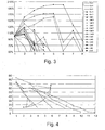
- FIG. 3 A chart showing the results of the first test is shown in Figure 3.
- the y-axis represents the Percentage of Cycle 1 Capacity
- the x-axis represents the Cycle Number.
- a battery separator with a conductive layer added to it may extend the cycle life of a battery.
- the cell with the silver paint added to the separator lasted twice as long as the other alternatives, including the control.
- FIG 4 A chart detailing the results of the second test is shown in Figure 4.
- the y-axis represents the Capacity in minutes and the x-axis represents the Week Number.
- the control batteries are represented by reference letter A, and the Test batteries are represented by reference letter B.
- battery separator 10 shows results for extending the cycle life of a battery. Additionally, capacity of a battery with a battery separator according to the instant invention may be higher than control batteries.
Abstract
Description
- The instant application relates to battery separators used in secondary batteries.
- A battery separator is a component that divides, or "separates", the positive electrode from the negative electrode within a battery cell. A battery separator has two primary functions. First, a battery separator must keep the positive electrode physically apart from the negative electrode in order to prevent any electronic current passing between the two electrodes. Second, a battery separator must permit an ionic current between the positive and negative electrodes with the least possible resistance. A battery separator can be made out of many different materials, but these two opposing functions have been best met by a battery separator being made of a porous nonconductor.
- An important parameter for describing a battery is the achievable number of cycles, or the cycle life of the battery. The cycle life indicates how often a battery can be charged and discharged repeatedly before a lower limit of the capacity is reached, or a failure. Batteries with a cycle life include all secondary batteries, or batteries that are capable of being recharged several times. There are many secondary batteries, including, but not limited to, lead-acid batteries. For economical and ecological reasons, batteries with a high cycle life are preferred.
- Many batteries have a low cycle life, or fail, due to deterioration of the positive electrode conductor. The positive electrode conductor, usually in the form of a grid in a lead-acid battery, deteriorates from corrosion during the electrochemical process. The positive electrode conductor corrodes faster than the negative electrode conductor because of the greater effects of the electrochemical process on the positive electrode. The more current flowing through the positive electrode conductor, the faster the positive electrode conductor deteriorates. The positive electrode conductor is a critical element of a battery as it provides the means for electrical current to flow to and from the positive electrode. Thus, when the positive electrode conductor deteriorates, electrical current to and from the battery deteriorates. This deterioration causes the battery power to deteriorate, which in turn leads to battery failure.
- Therefore, there is a need for extending the cycle life of a battery. More specifically, there is a need for extending the life of the positive electrode conductor to achieve extended cycle life of the battery.
- The instant invention is a battery separator for extending the cycle life of a battery. The battery separator has a separator and a conductive layer. The conductive layer is disposed upon the separator. The conductive layer is adapted to be in contact with the positive electrode of the battery thereby providing a new route of current to and from the positive electrode.
- For the purpose of illustrating the invention, there is shown in the drawings a form that is presently preferred; it being understood, however, that this invention is not limited to the precise arrangements and instrumentalities shown.
- Figure 1 is a fragmentary cross-sectional view of a battery with one embodiment of the battery separator of the present invention.
- Figure 2 is an isometric view of one embodiment of the battery separator of the present invention.
- Figure 3 is a line graph of the results of
test 1. - Figure 4 is a line graph of the results of
test 2. - Referring to the drawings, wherein like numerals indicate like elements, there is shown in Figure 1 an embodiment of a
battery separator 10 for extending the cycle life of abattery 12.Battery 12 may be any type of battery. More specifically,battery 12 may be any type of battery that may be susceptible to electrode conductor deterioration.Battery 12 may be a secondary battery. For example,battery 12 may be a lead-acid battery (as shown in Figure 1). - At least one
battery separator 10 may be included in battery 12 (see Figure 1). Preferably, onebattery separator 10 may be included in eachcell 24 ofbattery 12.Battery separator 10 may be for preventing any electronic current from passing between apositive electrode 16 and anegative electrode 17 while allowing ionic current to flow betweenpositive electrode 16 andnegative electrode 17. In addition,battery separator 10 may be for extending the cycle life ofbattery 12 by providing a new route of current to and frompositive electrode 16.Battery separator 10 may also extend the cycle life ofbattery 12 by functioning as a positive electrode conductor when the conductive capability ofpositive electrode conductor 18 deteriorates.Battery separator 10 may be made of any known battery separator materials, including, but not limited to, any porous nonconductor.Battery separator 10 may be any size or shape, including, but not limited to, flat or havingribs 22. Preferably,battery separator 10 may have ribs 22 (see Figure 2).Battery separator 10 may include aconductive layer 14. -
Conductive layer 14 may be disposed on battery separator 12 (see Figure 2).Conductive layer 14 may be adapted to be in contact withpositive electrode 16 of battery 12 (see Figure 1).Conductive layer 14 may be for providing a new route of current to and frompositive electrode 16.Conductive layer 14 may be made of any conductive material, including, but not limited to, lead, gold, antimony, arsenic, zinc, barium, beryllium, lithium, magnesium, nickel, aluminum, silver, tin, and combination alloys thereof, or carbon fibers, graphite, carbon nanotubes, or buckyballs. The carbon nanotubes or buckyballs might be dispersed in a medium with a binder and painted onbattery separator 10.Conductive layer 14 may be made of any conductive material that is more corrosion resistant thanpositive electrode conductor 18, thus, allowingconductive layer 14 to function as thepositive electrode conductor 18 when the conductive capability of thepositive electrode conductor 18 deteriorates.Conductive layer 14 may be a lead based alloy with 0.8% to 1.17% tin, and greater than zero (0) to 0.015% silver.Conductive layer 14 may be a lead-based alloy with 0.02% to 0.06% calcium, 0.3% to 3% tin, and 0.01% to 0.05% silver.Conductive layer 14 may be made into any form, including but not limited to, a strip, a screen, a foil, a thread, a wire, a coating, etc.Conductive layer 14 may be any thickness, including, but not limited to, a thickness of three (3) micro meters.Conductive layer 14 may be disposed uponbattery separator 10 by any means, including, but not limited to, adhesives, hot melting, painting, etc. -
Ribs 22 may be included onbattery separator 10.Ribs 22 may be for maintaining a maximum distance between thepositive electrode 16 and thebattery separator 10.Ribs 22 may also be for achieving the desired electrolyte distribution inbattery 12.Ribs 22 may be of any shape (straight, angled, waves, etc.) or form (triangular, circular, square, etc.).Ribs 22 may includetips 26. -
Tips 26 may be a component ofribs 22.Tips 26 may be the distal ends of eachrib 22.Tips 22 may be for providing a location forconductive layer 14 to be disposed onbattery separator 10 that allowsconductive layer 14 to be in contact withpositive electrode conductor 16. More specifically,tips 22 may be for providing a specific location forconductive layer 14 to be in contact withpositive electrode conductor 16, which allowsconductive layer 14 to be made out of the least amount of material for economical purposes. - For example, as shown in Figures 1-2,
battery separator 10 may be made of a porous nonconductor and haveribs 22 withtips 26.Conductive layer 14 may be made of a fine silver powder dispersed in a solvent and painted onto thetips 26 ofribs 22.Battery separator 10 may be used as the separator of eachcell 24 ofbattery 12. - In operation,
battery separator 10 may perform the functions of a battery separator. Meaning,battery separator 10 may keep thepositive electrode 16 physically apart from thenegative electrode 17 in order to prevent any electronic current from passing between the two electrodes, andbattery separator 10 may allow ionic current to flow between thepositive electrode 16 and thenegative electrode 17. These functions may allow the electrochemical process to take place and may force the electrical current to flow frompositive electrode conductor 18 tonegative electrode conductor 19, thus, allowingbattery 12 to provide energy. -
Battery separator 10 may also provide extended cycle life forbattery 12. Extended cycle life may be accomplished throughconductive layer 14.Conductive layer 14 may provide two ways of extending the cycle life forbattery 12. - First, because
conductive layer 14 may be adapted to contact thepositive electrode 16 ofbattery 12 andconductive layer 14 may be made out of a conductive material,conductive layer 14 may act as a second positive electrode conductor. This means thatconductive layer 14 may provide a new route of current to and frompositive electrode 16. This new route of current throughconductive layer 14 may reduce the amount of current throughpositive electrode conductor 18. Accordingly, the rate thatpositive electrode conductor 18 deteriorates may be reduced. Thus,conductive layer 14 may extend the cycle life ofbattery 12. - Second, because
conductive layer 14 may be adapted to be in contact withpositive electrode 16 providing a new route of current to and frompositive electrode 16, and becauseconductive layer 14 may be more corrosive resistant thanpositive electrode conductor 18,conductive layer 14 may function aspositive electrode conductor 18 when the conductive capability ofpositive electrode conductor 18 deteriorates. This means that when a control battery fails due to the positive electrode conductor deteriorating,battery 12 withbattery separator 10 may not fail becauseconductive layer 14 may function aspositive electrode conductor 18. - Thus,
battery separator 10, and more specifically,conductive layer 14 onbattery separator 10, may provide two ways of extending the cycle life ofbattery 12. - One three-plate cell was constructed using various alternatives to make the ends of the ribs conductive. The following are descriptions of the various ideas used:
- Cell A used strips of thin pure lead attached to the tips of the ribs with adhesive.
- Cell B used aluminum foil attached to the tips of several outer ribs using hot melt.
- Cells C1 and C2 used Aluminum foil that was attached to the tips of the ribs with hot melt, with a punctured solid layer of foil in the center of the separator. Two different ideas for evaluating the foils performance were used, one being with large "windows" and the other with small slits in the foil layer, thus, allowing electrolyte to flow freely.
- Cell D was the control material for the test.
- Cell E used Silver paint (fine silver powder dispersed in a solvent, used for coating SEM samples) that was painted onto the tips of the ribs of the separator. Roughly 1g of silver powder was applied to the separator, in a layer of approximately twenty (20) micro meters.
- These cells were formed and subjected to the following cycling regime: Discharged at 10A to 1.65V; Charged at 2.50V (10A limit) to 120%Ah removed; Discharged at 5A to 1.65V; Charged at 2.50V (10A limit) to 120%Ah removed; Discharged at 1A to 1.65V; Charged at 2.50V (10A limit) to 120%Ah removed; and Charged at 1A for 100 hours. This cycle was repeated until the capacity fell below 50% of initial capacity.
- A chart showing the results of the first test is shown in Figure 3. In Figure 3 the y-axis represents the Percentage of
Cycle 1 Capacity, and the x-axis represents the Cycle Number. - As shown from the result of
test 1, a battery separator with a conductive layer added to it may extend the cycle life of a battery. The cell with the silver paint added to the separator lasted twice as long as the other alternatives, including the control. - As a result of the work conducted and results achieved in
test 1, a second test was set up to verify the results of the first test (see Figure 4). For this test, a total of six complete batteries were built; three as controls and three with battery separators with silver on the tips of the ribs. These batteries were subsequently tested via the high temperature (75°C) SAE J-240 life test, with the following modification made: As the batteries were made in-house and did not have standard ratings or intercell connectors, the reserve capacity was measured instead of a discharge at the CCA rate. - A chart detailing the results of the second test is shown in Figure 4. In Figure 4, the y-axis represents the Capacity in minutes and the x-axis represents the Week Number. The control batteries are represented by reference letter A, and the Test batteries are represented by reference letter B.
- As a result of
test 2, the batteries with the silver painted on the ribs were confirmed to last longer than the control batteries. - Upon reviewing the results of the two battery tests conducted,
battery separator 10 shows results for extending the cycle life of a battery. Additionally, capacity of a battery with a battery separator according to the instant invention may be higher than control batteries. - The present invention may be embodied in other forms without departing from the spirit and the essential attributes thereof, and, accordingly, reference should be made to the appended claims, rather than to the foregoing specification, as indicated in the scope of the invention.
Claims (20)
- A battery separator for extending the cycle life of a battery comprising:a separator; anda conductive layer disposed upon said separator;whereby said conductive layer being adapted to contact an electrode of the battery thereby providing a new route for current to and from said electrode.
- The battery separator of claim 1 where said conductive layer being adapted to contact a positive electrode of said battery.
- The battery separator of claim 1 where said conductive layer being adapted to be more corrosion resistant than an electrode conductor of said battery, thereby allowing said conductive layer to function as said electrode conductor when the conductive capability of said electrode conductor deteriorates.
- The battery separator of claim 3 where said conductive layer being adapted to be more corrosion resistant than a positive electrode conductor of said battery, thereby allowing said conductive layer to function as said positive electrode conductor when the conductive capability of said positive electrode conductor deteriorates.
- The battery separator of claim 1 where said conductive layer being made of a conductive material.
- The battery separator of claim 5 where said conductive material being selected from the group consisting of lead, gold, antimony, arsenic, zinc, barium, beryllium, lithium, magnesium, nickel, aluminum, silver, tin, and combination alloys thereof.
- The battery separator of claim 5 where said conductive material being selected from the group consisting of carbon fibers, graphite, carbon nanotubes, and buckyballs.
- The battery separator of claim 1 where said conductive layer being strips.
- The battery separator of claim 1 where said conductive layer being a screen.
- The battery separator of claim 1 where said conductive layer being a foil.
- The battery separator of claim 1 where said conductive layer being a thread.
- The battery separator of claim 1 where said conductive layer being a wire.
- The battery separator of claim 1 where said conductive layer being a coating.
- The battery separator of claim 1 where said conductive layer being disposed upon said separator by adhesively bonding said conductive layer on said separator.
- The battery separator of claim 1 where said conductive layer being disposed upon said separator by hot melting said conductive layer on said separator.
- The battery separator of claim 1 where said conductive layer being disposed upon said separator by painting said conductive layer on said separator.
- The battery separator of claim 1 where said separator having ribs.
- The battery separator of claim 17 where said conductive layer being painted onto the tips of said ribs.
- The battery separator of claim 1 being used in a lead-acid battery.
- A battery separator for extending the cycle life of a battery comprising:a separator having ribs with tips; anda conductive layer being disposed upon said separator;said conductive layer being silver particles disposed in a solvent being painted onto said tips;whereby said conductive layer being adapted to contact a positive electrode of the battery thereby providing a new route for current to and from said positive electrode.
Applications Claiming Priority (1)
| Application Number | Priority Date | Filing Date | Title |
|---|---|---|---|
| US11/535,701 US9564623B2 (en) | 2006-09-27 | 2006-09-27 | Battery separator with a conductive layer for extending the cycle life of a battery |
Publications (2)
| Publication Number | Publication Date |
|---|---|
| EP1906471A1 true EP1906471A1 (en) | 2008-04-02 |
| EP1906471B1 EP1906471B1 (en) | 2011-09-14 |
Family
ID=38656603
Family Applications (1)
| Application Number | Title | Priority Date | Filing Date |
|---|---|---|---|
| EP07018273A Active EP1906471B1 (en) | 2006-09-27 | 2007-09-18 | A battery separator for extending the cycle life of a battery |
Country Status (5)
| Country | Link |
|---|---|
| US (3) | US9564623B2 (en) |
| EP (1) | EP1906471B1 (en) |
| JP (1) | JP4995020B2 (en) |
| KR (1) | KR100924413B1 (en) |
| ES (1) | ES2371780T3 (en) |
Cited By (4)
| Publication number | Priority date | Publication date | Assignee | Title |
|---|---|---|---|---|
| WO2009155267A1 (en) * | 2008-06-20 | 2009-12-23 | Mysticmd, Inc. | Anode, cathode, grid and current collector material for reduced weight battery and process for production thereof |
| EP2378592A2 (en) * | 2008-12-30 | 2011-10-19 | LG Chem, Ltd. | Separator with a porous coating layer, and electrochemical device comprising same |
| CN106025154A (en) * | 2010-09-22 | 2016-10-12 | 达拉米克有限责任公司 | Separators, batteries, systems, and methods for idle start stop vehicles |
| DE102017218416A1 (en) * | 2017-10-16 | 2019-04-18 | Robert Bosch Gmbh | Electrode unit for a battery cell and battery cell |
Families Citing this family (19)
| Publication number | Priority date | Publication date | Assignee | Title |
|---|---|---|---|---|
| US9564623B2 (en) * | 2006-09-27 | 2017-02-07 | Daramic Llc | Battery separator with a conductive layer for extending the cycle life of a battery |
| EP2469624A1 (en) | 2009-08-19 | 2012-06-27 | Mitsubishi Chemical Corporation | Separator for non-aqueous electrolyte secondary battery and non-aqueous electrolyte secondary battery |
| JP2012043627A (en) * | 2010-08-18 | 2012-03-01 | Mitsubishi Chemicals Corp | Nonaqueous electrolyte secondary battery |
| US10411236B2 (en) | 2012-04-12 | 2019-09-10 | Johns Manville | Mat made of glass fibers or polyolefin fibers used as a separator in a lead-acid battery |
| JP5969927B2 (en) | 2013-01-18 | 2016-08-17 | 株式会社 日立パワーデバイス | Diode, power converter |
| US10084170B2 (en) | 2013-10-03 | 2018-09-25 | Johns Manville | Pasting paper made of glass fiber nonwoven comprising carbon graphite |
| US9685646B2 (en) | 2013-10-03 | 2017-06-20 | Johns Manville | Pasting paper made of glass fiber nonwoven comprising carbon graphite |
| US9923196B2 (en) * | 2013-10-03 | 2018-03-20 | Johns Manville | Conductive mat for battery electrode plate reinforcement and methods of use therefor |
| CN112542654A (en) * | 2014-01-02 | 2021-03-23 | 达拉米克有限责任公司 | Multilayer separator and methods of making and using |
| KR20240023205A (en) * | 2014-05-05 | 2024-02-20 | 다라믹 엘엘씨 | Improved lead-acid battery separators, electrodes, batteries, and methods of manufacture and use thereof |
| KR20180053417A (en) * | 2015-10-05 | 2018-05-21 | 다라믹 엘엘씨 | Functional lead-acid battery separators, improved lead acid batteries and related methods |
| CN106450114A (en) * | 2016-12-14 | 2017-02-22 | 镇江泰舸电池隔膜科技有限公司 | Battery separator with embedded ribs |
| WO2018236973A1 (en) | 2017-06-20 | 2018-12-27 | Daramic, Llc | Improved lead acid battery separators, batteries, and related methods |
| WO2019028516A1 (en) * | 2017-08-08 | 2019-02-14 | Cape Bouvard Technologies Pty Ltd | A structural battery |
| JP7405740B2 (en) * | 2017-09-08 | 2023-12-26 | ダラミック エルエルシー | Improved lead acid battery separator incorporating carbon |
| WO2020051100A1 (en) | 2018-09-04 | 2020-03-12 | Daramic, Llc | Battery separators, electrode assemblies, systems and related methods |
| EP3912219A4 (en) * | 2019-01-16 | 2023-03-29 | Daramic, LLC | Improved z wrap separators, cells, systems, batteries, and related equipment and methods |
| CN110707368B (en) * | 2019-09-11 | 2021-06-01 | 天能电池集团股份有限公司 | Electrolyte-layering-resistant storage battery pole group and lead storage battery |
| KR102377898B1 (en) | 2020-06-04 | 2022-03-24 | 한국앤컴퍼니 주식회사 | Lead-acid battery separator manufacturing method with reinforced edge contact |
Citations (7)
| Publication number | Priority date | Publication date | Assignee | Title |
|---|---|---|---|---|
| US3539374A (en) * | 1966-11-16 | 1970-11-10 | Celanese Corp | Porous article |
| JPS55157859A (en) * | 1979-05-25 | 1980-12-08 | Japan Storage Battery Co Ltd | Lead storage battery |
| GB2070847A (en) * | 1980-02-27 | 1981-09-09 | Celanese Corp | Coated open-celled microporous membranes for eg battery separators |
| DE3110168A1 (en) * | 1981-03-16 | 1982-09-23 | Hans 5480 Remagen Kessel | Process for producing a laminate from a permeable metallic substrate and a porous plastic |
| JPS62291871A (en) * | 1986-06-10 | 1987-12-18 | Matsushita Electric Ind Co Ltd | Enclosed type nickel-cadmium storage battery |
| JPS646373A (en) * | 1987-06-29 | 1989-01-10 | Matsushita Electric Ind Co Ltd | Lead storage battery |
| WO2004112166A2 (en) * | 2003-06-13 | 2004-12-23 | Daramic, Llc. | Separator material for forming a separator for a lead-acid accumulator |
Family Cites Families (19)
| Publication number | Priority date | Publication date | Assignee | Title |
|---|---|---|---|---|
| US3542596A (en) * | 1967-10-18 | 1970-11-24 | Mc Donnell Douglas Corp | Battery separator |
| US3554814A (en) * | 1969-02-13 | 1971-01-12 | Mc Donnell Douglas Corp | Inorganic separator and process for producing same |
| US3877985A (en) * | 1971-06-18 | 1975-04-15 | Gen Electric | Cell having anode containing silver additive for enhanced oxygen recombination |
| US4009056A (en) * | 1976-03-15 | 1977-02-22 | Esb Incorporated | Primary alkaline cell having a stable divalent silver oxide depolarizer mix |
| JPS5911183B2 (en) * | 1976-08-24 | 1984-03-14 | 株式会社ユアサコーポレーション | silver peroxide battery |
| US4245013A (en) * | 1978-05-11 | 1981-01-13 | Chloride Group Limited | Battery separators |
| JPH03203158A (en) | 1989-12-28 | 1991-09-04 | Shin Kobe Electric Mach Co Ltd | Lead-acid battery |
| US5691087A (en) * | 1991-03-26 | 1997-11-25 | Gnb Technologies, Inc. | Sealed lead-acid cells and batteries |
| US5874186A (en) * | 1991-03-26 | 1999-02-23 | Gnb Technologies, Inc. | Lead-acid cells and batteries |
| JP3122041B2 (en) | 1996-06-20 | 2001-01-09 | 住友重機械工業株式会社 | Method for preventing carbide from entering resin during injection molding, and screw for preventing carbide from entering |
| BR9809270A (en) * | 1997-05-07 | 2004-06-29 | Gnb Tech Inc | Sealed Lead Acid Cell, Positive Plate and Lead Acid Battery |
| KR100240743B1 (en) * | 1997-07-14 | 2000-01-15 | 성재갑 | Lithium secondary battery using battery separators having conductive coating |
| ATE221925T1 (en) * | 1998-06-26 | 2002-08-15 | Johnson Controls Tech Co | ALLOY FOR GRIDS IN LEAD ADDED ACCUMULATORS |
| US6524742B1 (en) * | 1999-02-19 | 2003-02-25 | Amtek Research International Llc | Electrically conductive, freestanding microporous polymer sheet |
| US6704192B2 (en) * | 1999-02-19 | 2004-03-09 | Amtek Research International Llc | Electrically conductive, freestanding microporous sheet for use in an ultracapacitor |
| EP1160900A3 (en) * | 2000-05-26 | 2007-12-12 | Kabushiki Kaisha Riken | Embossed current collector separator for electrochemical fuel cell |
| DE60137590D1 (en) * | 2000-12-06 | 2009-03-19 | Omlidon Technologies Llc | Melt-processable, wear-resistant polyethylene |
| KR20050021131A (en) * | 2003-08-26 | 2005-03-07 | 대한민국 (경상대학교 총장) | Lithium/sulfur secondary batteries with coated separator having improved charge and discharge properties |
| US9564623B2 (en) * | 2006-09-27 | 2017-02-07 | Daramic Llc | Battery separator with a conductive layer for extending the cycle life of a battery |
-
2006
- 2006-09-27 US US11/535,701 patent/US9564623B2/en active Active
-
2007
- 2007-08-27 KR KR1020070086120A patent/KR100924413B1/en active IP Right Grant
- 2007-09-18 ES ES07018273T patent/ES2371780T3/en active Active
- 2007-09-18 EP EP07018273A patent/EP1906471B1/en active Active
- 2007-09-27 JP JP2007250936A patent/JP4995020B2/en active Active
-
2016
- 2016-12-23 US US15/389,938 patent/US10361416B2/en active Active
-
2019
- 2019-07-23 US US16/519,312 patent/US11450924B2/en active Active
Patent Citations (7)
| Publication number | Priority date | Publication date | Assignee | Title |
|---|---|---|---|---|
| US3539374A (en) * | 1966-11-16 | 1970-11-10 | Celanese Corp | Porous article |
| JPS55157859A (en) * | 1979-05-25 | 1980-12-08 | Japan Storage Battery Co Ltd | Lead storage battery |
| GB2070847A (en) * | 1980-02-27 | 1981-09-09 | Celanese Corp | Coated open-celled microporous membranes for eg battery separators |
| DE3110168A1 (en) * | 1981-03-16 | 1982-09-23 | Hans 5480 Remagen Kessel | Process for producing a laminate from a permeable metallic substrate and a porous plastic |
| JPS62291871A (en) * | 1986-06-10 | 1987-12-18 | Matsushita Electric Ind Co Ltd | Enclosed type nickel-cadmium storage battery |
| JPS646373A (en) * | 1987-06-29 | 1989-01-10 | Matsushita Electric Ind Co Ltd | Lead storage battery |
| WO2004112166A2 (en) * | 2003-06-13 | 2004-12-23 | Daramic, Llc. | Separator material for forming a separator for a lead-acid accumulator |
Cited By (6)
| Publication number | Priority date | Publication date | Assignee | Title |
|---|---|---|---|---|
| WO2009155267A1 (en) * | 2008-06-20 | 2009-12-23 | Mysticmd, Inc. | Anode, cathode, grid and current collector material for reduced weight battery and process for production thereof |
| EP2378592A2 (en) * | 2008-12-30 | 2011-10-19 | LG Chem, Ltd. | Separator with a porous coating layer, and electrochemical device comprising same |
| EP2378592A4 (en) * | 2008-12-30 | 2012-12-19 | Lg Chemical Ltd | Separator with a porous coating layer, and electrochemical device comprising same |
| US8703323B2 (en) | 2008-12-30 | 2014-04-22 | Lg Chem, Ltd. | Separator including porous coating layer and electrochemical device including the same |
| CN106025154A (en) * | 2010-09-22 | 2016-10-12 | 达拉米克有限责任公司 | Separators, batteries, systems, and methods for idle start stop vehicles |
| DE102017218416A1 (en) * | 2017-10-16 | 2019-04-18 | Robert Bosch Gmbh | Electrode unit for a battery cell and battery cell |
Also Published As
| Publication number | Publication date |
|---|---|
| US20190348659A1 (en) | 2019-11-14 |
| KR20080028765A (en) | 2008-04-01 |
| EP1906471B1 (en) | 2011-09-14 |
| US20170110702A1 (en) | 2017-04-20 |
| JP2008084866A (en) | 2008-04-10 |
| US11450924B2 (en) | 2022-09-20 |
| US20080076028A1 (en) | 2008-03-27 |
| US9564623B2 (en) | 2017-02-07 |
| KR100924413B1 (en) | 2009-10-29 |
| US10361416B2 (en) | 2019-07-23 |
| ES2371780T3 (en) | 2012-01-10 |
| JP4995020B2 (en) | 2012-08-08 |
Similar Documents
| Publication | Publication Date | Title |
|---|---|---|
| US11450924B2 (en) | Battery separator for extending the cycle life of a battery | |
| US9887410B2 (en) | Flexible fusible link, systems, and methods | |
| US20230268561A1 (en) | Rechargeable battery with temperature activated current interrupter | |
| JP5459319B2 (en) | Vehicle system and hydrogen sulfide detection method | |
| JP5923178B2 (en) | Negative electrode for cable type secondary battery and cable type secondary battery including the same | |
| JP6930497B2 (en) | Laminated battery | |
| WO1999067836A1 (en) | Cell and method of producing the same | |
| WO1999067837A1 (en) | Electrode, method of producing electrode, and cell comprising the electrode | |
| KR20160121179A (en) | A lithium ion secondary battery comprising a reference electrode | |
| US20230344092A1 (en) | Electrode assemblies including current limiters, secondary batteries having such electrode assemblies, and methods of testing | |
| KR101059891B1 (en) | High power electrical energy storage device having a unit cell and the unit cell | |
| WO2005060024A2 (en) | Voltaic element | |
| JPH10513598A (en) | Alkaline storage battery | |
| CN116565467B (en) | Electrochemical device and electric equipment | |
| CN1288792C (en) | Battery | |
| KR20010020338A (en) | Electrode, method of fabricating thereof, and battery using thereof | |
| EP3457462A1 (en) | Rechargeable battery | |
| KR20210055298A (en) | Lithium seconday battery and security system for lithium seconday battery | |
| WO2024077132A2 (en) | Electrode assemblies for secondary batteries that include current limiters | |
| KR20210155670A (en) | Electrode for lihium secondary battery including low melting binder, electrode assembly and lithium secondary battery including the same | |
| KR20060112739A (en) | Anode plate and secondary battery with the same |
Legal Events
| Date | Code | Title | Description |
|---|---|---|---|
| PUAI | Public reference made under article 153(3) epc to a published international application that has entered the european phase |
Free format text: ORIGINAL CODE: 0009012 |
|
| AK | Designated contracting states |
Kind code of ref document: A1 Designated state(s): AT BE BG CH CY CZ DE DK EE ES FI FR GB GR HU IE IS IT LI LT LU LV MC MT NL PL PT RO SE SI SK TR |
|
| AX | Request for extension of the european patent |
Extension state: AL BA HR MK YU |
|
| 17P | Request for examination filed |
Effective date: 20080425 |
|
| 17Q | First examination report despatched |
Effective date: 20080613 |
|
| AKX | Designation fees paid |
Designated state(s): DE ES FR GB IT |
|
| GRAP | Despatch of communication of intention to grant a patent |
Free format text: ORIGINAL CODE: EPIDOSNIGR1 |
|
| GRAS | Grant fee paid |
Free format text: ORIGINAL CODE: EPIDOSNIGR3 |
|
| GRAA | (expected) grant |
Free format text: ORIGINAL CODE: 0009210 |
|
| AK | Designated contracting states |
Kind code of ref document: B1 Designated state(s): DE ES FR GB IT |
|
| REG | Reference to a national code |
Ref country code: GB Ref legal event code: FG4D |
|
| REG | Reference to a national code |
Ref country code: DE Ref legal event code: R096 Ref document number: 602007017111 Country of ref document: DE Effective date: 20111117 |
|
| REG | Reference to a national code |
Ref country code: ES Ref legal event code: FG2A Ref document number: 2371780 Country of ref document: ES Kind code of ref document: T3 Effective date: 20120110 |
|
| PLBE | No opposition filed within time limit |
Free format text: ORIGINAL CODE: 0009261 |
|
| STAA | Information on the status of an ep patent application or granted ep patent |
Free format text: STATUS: NO OPPOSITION FILED WITHIN TIME LIMIT |
|
| 26N | No opposition filed |
Effective date: 20120615 |
|
| REG | Reference to a national code |
Ref country code: DE Ref legal event code: R097 Ref document number: 602007017111 Country of ref document: DE Effective date: 20120615 |
|
| REG | Reference to a national code |
Ref country code: FR Ref legal event code: PLFP Year of fee payment: 10 |
|
| REG | Reference to a national code |
Ref country code: FR Ref legal event code: PLFP Year of fee payment: 11 |
|
| REG | Reference to a national code |
Ref country code: FR Ref legal event code: PLFP Year of fee payment: 12 |
|
| REG | Reference to a national code |
Ref country code: DE Ref legal event code: R079 Ref document number: 602007017111 Country of ref document: DE Free format text: PREVIOUS MAIN CLASS: H01M0002160000 Ipc: H01M0050409000 |
|
| PGFP | Annual fee paid to national office [announced via postgrant information from national office to epo] |
Ref country code: GB Payment date: 20220810 Year of fee payment: 16 Ref country code: DE Payment date: 20220615 Year of fee payment: 16 |
|
| PGFP | Annual fee paid to national office [announced via postgrant information from national office to epo] |
Ref country code: FR Payment date: 20220810 Year of fee payment: 16 |
|
| PGFP | Annual fee paid to national office [announced via postgrant information from national office to epo] |
Ref country code: IT Payment date: 20220929 Year of fee payment: 16 Ref country code: ES Payment date: 20221007 Year of fee payment: 16 |
|
| P01 | Opt-out of the competence of the unified patent court (upc) registered |
Effective date: 20230706 |