EP1903963B1 - Device for interconnecting components in spinal instrumentation with rods - Google Patents
Device for interconnecting components in spinal instrumentation with rods Download PDFInfo
- Publication number
- EP1903963B1 EP1903963B1 EP06752059A EP06752059A EP1903963B1 EP 1903963 B1 EP1903963 B1 EP 1903963B1 EP 06752059 A EP06752059 A EP 06752059A EP 06752059 A EP06752059 A EP 06752059A EP 1903963 B1 EP1903963 B1 EP 1903963B1
- Authority
- EP
- European Patent Office
- Prior art keywords
- connector body
- clamp element
- receptacle
- clamp
- passage
- Prior art date
- Legal status (The legal status is an assumption and is not a legal conclusion. Google has not performed a legal analysis and makes no representation as to the accuracy of the status listed.)
- Not-in-force
Links
Images


Classifications
-
- A—HUMAN NECESSITIES
- A61—MEDICAL OR VETERINARY SCIENCE; HYGIENE
- A61B—DIAGNOSIS; SURGERY; IDENTIFICATION
- A61B17/00—Surgical instruments, devices or methods, e.g. tourniquets
- A61B17/56—Surgical instruments or methods for treatment of bones or joints; Devices specially adapted therefor
- A61B17/58—Surgical instruments or methods for treatment of bones or joints; Devices specially adapted therefor for osteosynthesis, e.g. bone plates, screws, setting implements or the like
- A61B17/68—Internal fixation devices, including fasteners and spinal fixators, even if a part thereof projects from the skin
- A61B17/70—Spinal positioners or stabilisers ; Bone stabilisers comprising fluid filler in an implant
- A61B17/7049—Connectors, not bearing on the vertebrae, for linking longitudinal elements together
- A61B17/705—Connectors, not bearing on the vertebrae, for linking longitudinal elements together for linking adjacent ends of longitudinal elements
-
- A—HUMAN NECESSITIES
- A61—MEDICAL OR VETERINARY SCIENCE; HYGIENE
- A61B—DIAGNOSIS; SURGERY; IDENTIFICATION
- A61B17/00—Surgical instruments, devices or methods, e.g. tourniquets
- A61B17/56—Surgical instruments or methods for treatment of bones or joints; Devices specially adapted therefor
- A61B17/58—Surgical instruments or methods for treatment of bones or joints; Devices specially adapted therefor for osteosynthesis, e.g. bone plates, screws, setting implements or the like
- A61B17/68—Internal fixation devices, including fasteners and spinal fixators, even if a part thereof projects from the skin
- A61B17/70—Spinal positioners or stabilisers ; Bone stabilisers comprising fluid filler in an implant
- A61B17/7049—Connectors, not bearing on the vertebrae, for linking longitudinal elements together
Landscapes
- Health & Medical Sciences (AREA)
- Orthopedic Medicine & Surgery (AREA)
- Life Sciences & Earth Sciences (AREA)
- Neurology (AREA)
- Surgery (AREA)
- Heart & Thoracic Surgery (AREA)
- Engineering & Computer Science (AREA)
- Biomedical Technology (AREA)
- Nuclear Medicine, Radiotherapy & Molecular Imaging (AREA)
- Medical Informatics (AREA)
- Molecular Biology (AREA)
- Animal Behavior & Ethology (AREA)
- General Health & Medical Sciences (AREA)
- Public Health (AREA)
- Veterinary Medicine (AREA)
- Surgical Instruments (AREA)
- Prostheses (AREA)
Abstract
Description
- The present invention relates generally to instrumentation for treatment of the spinal column, and more particularly relates to devices for interconnecting components in spinal instrumentation.
- Several techniques and systems have been developed for use in treatment of the spinal column, and more specifically for stabilizing and supporting portions of the spinal column. Elongate rods are sometimes used to stabilize and support portions of the spinal column in an attempt to correct spinal deformities or curvatures relating to scoliosis or other conditions. In certain instances involving spinal disorders or degenerative conditions, the treatment techniques and systems are used in association with spinal fusion techniques to promote fusion between one or more pairs of adjacent vertebrae.
- In some techniques and systems, elongate rods are positioned along opposite sides of the spinal column. The elongate rods are engaged to two or more vertebrae by way of a number of anchor elements, such as screws and/or hooks, to provide a spinal construct that functions to stabilize and support at least a portion of the spinal column. The overall structural integrity and stability of the spinal construct is sometimes enhanced by providing one or more transverse connectors that interconnect the elongate rods at one or more locations along the length of the rods. The transverse connectors link the rods together to prevent rod migration and to increase the overall stiffness of the spinal construct. In cases involving spinal fusion, the use of transverse connectors is particularly beneficial in stabilizing/ stiffening the spinal construct to enhance or promote fusion between one or more pairs of adjacent vertebrae.
- Many prior transverse connectors present one or more difficulties for spinal surgeons. For example, some prior transverse connectors have a relatively high profile which potentially increases soft tissue trauma and surgical complications. Additionally, some prior transverse connectors must be preloaded onto the elongate rods prior to implantation within the patient. Such preloading may require significant pre-operative planning and eliminates the opportunity to engage the transverse connectors to the elongate rods in situ. Further, adjusting the position of the transverse connectors during the surgical procedure can be difficult to accomplish.
- Thus, there is a general need in the industry to provide an improved device for interconnecting components in spinal instrumentation. The present invention satisfies this need and provides other benefits and advantages in a novel and unobvious manner.
-
WO 99/09901 US 5,989,250 describes a spinal fixation implant system.US 2003/0028192 A1 describes a device or releasably clamping and connecting a longitudinal member within a surgical implant. - The present invention relates generally to devices for interconnecting components in spinal instrumentation. While the actual nature of the invention covered herein can only be determined with reference to the claims appended hereto, certain forms of the invention that are characteristic of the preferred embodiments disclosed herein are described briefly as follows.
- According to the present invention, a device is provided for connection to a component used in association with spinal instrumentation, including a connector body, a clamp element and a fixation element. The connector body defines a receptacle extending therethrough and opening onto an outer surface thereof, with the receptacle including a pair of oppositely facing tapered engagement surfaces. The connector body further defines a passage in transverse communication with the receptacle. The clamp element includes at least two arm portions defining a space therebetween having an open end. The clamp element is positioned within the passage in the connector body with the space between the arm portions generally aligned with the receptacle and with the component received through the open end and retained within the space. The fixation element interacts with the clamp element to displace the clamp element relative to the connector body to engage the component against the tapered engagement surfaces.
- It is one object of the present invention to provide an improved device for interconnecting components in spinal instrumentation. Further objects, features, advantages, benefits, and aspects of the present invention will become apparent from the drawings and description contained herein.
-
-
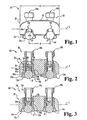
FIG. 1 is a side view of a connection device according to one form of the present invention for interconnecting a pair of elongate spinal rods. -
FIG. 2 is a side cross-sectional view of the connection device illustrated inFIG. 1 , as shown in a first operational configuration. -
FIG. 3 is a side cross-sectional view of the connection device illustrated inFIG. 1 , as shown in a second operational configuration. -
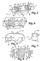
FIG. 4 is a perspective view of a connector body according to one embodiment of the present invention for use in association with the connection device illustrated inFIG. 1 . -
FIG. 5 is a side view of the connector body illustrated inFIG. 4 . -
FIG. 6 is a top view of the connector body illustrated inFIG. 4 . -
FIG. 7 is an end view of the connector body illustrated inFIG. 4 . -
FIG. 8 is a cross-sectional view of the connector body illustrated inFIG. 4 , as taken along line 8-8 ofFIG. 6 . -
FIG. 9 is a perspective view of a clamp element according to one embodiment of the present invention for use in association with the connection device illustrated inFIG. 1 . -
FIG. 10 is a side view of the clamp element illustrated inFIG. 9 . -
FIG. 11 is a top view of the clamp element illustrated inFIG. 9 . -
FIG. 12 is an end view of the clamp element illustrated inFIG. 9 . -
FIG. 13 is a cross-sectional view of the clamp element illustrated inFIG. 9 , as taken along line 13-13 ofFIG. 11 . -
FIG. 14 is a side view of a fixation element according to one embodiment of the present invention for use in association with the connection device illustrated inFIG. 1 . -
FIG. 15 is a cross-sectional side view of the fixation element illustrated inFIG. 14 . -
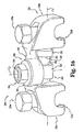
FIG. 16 is a perspective view of a connection device according to another form of the present invention for interconnecting a pair of elongate spinal rods. - For the purposes of promoting an understanding of the principles of the invention, reference will now be made to the embodiments illustrated in the drawings and specific language will be used to describe the same. It will nevertheless be understood that no limitation on the scope of the invention is hereby intended.
- Referring to
FIG. 1 , shown therein is aconnection device 20 according to one form of the present invention for interconnecting components used in association with spinal instrumentation. In the illustrated embodiment, theconnection device 20 is used to transversely connect a pair of elongate spinal rods R. The elongate spinal rods R are in turn attached to opposite sides of the spinal column by way of a number of anchor elements (not shown), such as screws or hooks, to form a spinal construct that stabilizes and supports the spinal column and, in some instances, serves to facilitate spinal fusion between one or more pairs of adjacent vertebrae. - In one embodiment of the invention, the spinal construct is attached to a posterior aspect of the spinal column. However, attachment of the spinal construct to other aspects or portions of the spinal column is also contemplated as falling within the scope of the present invention. The details regarding attachment of the elongate rods R to the spinal column are well known to those of skill in the art and therefore need not be specifically discussed herein. However, one example of the attachment of a pair of elongate rods to the spinal column is illustrated and described in
U.S. Patent No. 6,402,751 to Van Hoeck et al.. Although the illustrated embodiment of theconnection device 20 is used to interconnect a pair of elongate spinal rods R, it should be understood that connection devices according to other forms of the present invention may be used to interconnect other types of spinal instrumentation components. For example, connection devices according to other forms of the present invention may be used to interconnect a rod to a plate, a rod to a screw or hook, a rod to an implant, or any component or device associated with spinal constructs or assemblies to any other spinal component or device. - In one embodiment of the invention, the
connection device 20 generally includes aconnector body 22, one or more clamp elements orpincers 24, and one or more fixation elements orfasteners 26 configured to compress theclamp element 24 about a component used in association with spinal instrumentation. As indicated above, in the illustrated embodiment, theconnection device 20 is used to transversely interconnect a pair of elongate spinal rods R. Accordingly, theconnection device 20 includes aconnector body 22, a pair ofclamp elements 24a, 24b configured to receive respective ones of the spinal rods R therein, and a pair offixation elements clamp elements 24a, 24b about respective ones of the spinal rods R. However, as should be appreciated, connection devices according to other forms of the present invention may include a single clamp element and a corresponding fixation element, or three or more clamp elements and a corresponding number of fixation elements. Additionally, in the illustrated embodiment of the invention, theconnection device 20 is configured to interconnect the spinal rods R in a substantially parallel configuration and a co-planar arrangement. However, in other embodiments, the connection device may be configured to interconnect the spinal rods in a non-parallel or oblique configuration and/or in a non-planar arrangement. Additionally, in the illustrated embodiment, theconnection device 20 is configured to interconnect the spinal rods R in a manner wherein the distance d between the spinal rods R is fixed. However, in other embodiments, theconnection device 20 may be configured to interconnect the spinal rods such that the distance d between the spinal' rods R is variable or adjustable. - Referring to
FIGS. 2 and 3 , show therein is theconnection device 20 in two distinct operational configurations. With reference toFIG. 2 , theconnection device 20 is shown in a first operational configuration wherein theclamp elements 24a, 24b are provisionally engaged to the spinal rods R in such a manner as to allow theconnection device 20 to be displaced relative to the spinal rods R. In one embodiment, theconnection device 20 is capable of being axially displaced along a length of the spinal rods R when in the first operational configuration illustrated inFIG. 2 . Additionally, when in the first operational configuration, theconnection device 20 is capable of being rotated about the longitudinal axis of one or both of the spinal rods R. As will be discussed further below, theclamp elements 24a, 24b are loosely engaged about the spinal rods R when in the first operational configuration. However, theclamp elements 24a, 24b are drawn toward theconnector body 22 in response to engagement between thefixation elements clamp elements 24a, 24b to transition theconnection device 20 to the second operational configuration illustrated inFIG. 3 . When transitioned toward the second operational configuration, theclamp elements 24a, 24b are compressed about the spinal rods R in a manner which securely engages theconnection device 20 to the spinal rods R to substantially prevent displacement of theconnection device 20 relative to the spinal rods R, the details of which will be discussed below. - In the illustrated embodiment of the invention, the
bridge portion 28 of theconnector body 22 is substantially rigid and non-adjustable. Accordingly, theconnection device 20 has a non-adjustable length l to correspondingly interconnect the spinal rods R in a manner wherein the distance d between the spinal rods R is fixed. However, as will be discussed below with regard toFIG. 16 , other embodiments of connection devices are also contemplated wherein the length of the connector body is adjustable such that the distance d between the spinal rods R is correspondingly adjustable. Additionally, as also illustrated inFIG. 16 , connection devices are contemplated wherein the spinal rods R may be angulated relative to one another along a common plane and/or along different planes. Further embodiments of connection devices are also contemplated wherein the bridge portion of the connector body may include a region of reduced strength (such as a reduced cross sectional area) that allows for contouring or bending of the connector body as needed to conform to the spinal anatomy of the patient and/or to allow the spinal rods R to be angulated relative to one another along a common plane and/or along different planes. - Referring to
FIGS. 4-8 , shown there are further details regarding theconnector body 22. In one embodiment, theconnector body 22 is formed of a titanium alloy material such as, for example, Ti-6Al-4V. However, other materials are also contemplated, including titanium, stainless steel, or other materials know to those of skill in the art. In the illustrated embodiment, theconnector body 22 has a generally rectangular configuration extending along a longitudinal axis L. The upper corner portions of theconnector body 22 are rounded to prevent or at least minimize injury or trauma to adjacent tissue. Theconnector body 22 can be provided in different overall lengths l to accommodate for various distances d between the spinal rods R. - In the illustrated embodiment of the invention, the
connector body 22 defines one ormore receptacles 30 extending transversely across the width w of theconnector body 22 betweenopposite side surfaces receptacles 30 defines anopening 34 adjacent alower surface 36 of theconnector body 22. Thereceptacles 30 and theopenings 34 are each sized and configured to receive a spinal rod R therein. In the illustrated embodiment, theconnector body 22 includes a pair of receptacles orchannels single receptacle 30 or three ormore receptacles 30. - Each of the
receptacles 30 are defined by a pair of taperedside walls 40a, 40b that extend from thelower surface 36 of theconnector body 22 to anupper surface 42. In one embodiment, the taperedside walls 40a, 40b define a taper angle therebetween of about 30 degrees; however, other taper angles are also contemplated as falling with the scope of the present invention. In the illustrated embodiment, the taperedside walls 40a, 40b transition into theupper surface 42 by way of arcuate orrounded surfaces 43a, 43b. However, it should be understood that other configurations of thereceptacles 30 are also contemplated as falling within the scope of the present invention. Theconnector body 22 also defines an inner tapered region 44 (FIG. 8 ) adjacent each of thereceptacles 30. The inner taperedregion 44 does not extend the full width w of theconnector body 22, but instead stops short of the side surfaces 32a, 32b. The inner tapered region, 44 defines a pair of taperedengagement surfaces 46a, 46b that are outwardly offset in an axial direction relative to the taperedside walls 40a, 40b defined by thereceptacles 30. In one embodiment, the taperedengagement surfaces 46a, 46b define a taper angle therebetween of about 40 degrees; however, other taper angles are also contemplated as falling with the scope of the present invention. The purpose of the taperedengagement surfaces 46a, 46b will be discussed below. - The
connector body 22 further defines apassage 50 extending from theupper surface 38 of theconnector body 22 and communicating with a respective one of thereceptacles 30 and innertapered regions 44. As indicated above, in the illustrated embodiment, theconnector body 22 includes a pair ofreceptacles passages receptacles passages upper portion 52 having a generally circular configuration; however, other shapes and configurations are also contemplated. Each of thepassages lower portion 54 defined by a pair of generallyrectangular apertures bridge member 58. However, other shapes and configurations of theapertures bridge member 58 is generally disposed between theupper portion 52 of thepassages receptacles shoulder 60. Theupper portion 52 of thepassages channels 66a, 66b that are generally aligned with theapertures bridge member 58. However, it should be understood that the recessedregions 66a, 66b need not necessarily be aligned with theapertures regions 66a, 66b includes anouter wall 68 that is generally contiguous with the taperedengagement surfaces 46a, 46b. - Referring to
FIGS. 9-13 , shown there are further details regarding theclamp element 24. In one embodiment, theclamp element 24 is formed of a titanium alloy material such as, for example, Ti-6Al-4V. However, other materials are also contemplated, including titanium, stainless steel, plastic or polymeric materials, or other materials know to those of skill in the art. In the illustrated embodiment, theclamp element 24 includes abase portion 70 and a pair of opposite arm orpincer portions base portion 70. The interconnection between thebase portion 70 and thearms aims clamp element 24 to be positioned over and compressed or clamped about one of the spinal rods R. - In one embodiment, the
arms base portion 70 such that thearms arms arms base portion 70 so as to define a unitary, single-piece clamp element 24. However, other embodiments are also contemplated wherein thearms base 70. For example, in one alternative embodiment, thearms base 70 by a hinge or pivot pin. - In the illustrated embodiment of the invention, the
base 70 has an annular ring-like configuration defining an outer profile sized and shaped to generally correspond to the inner profile of theupper portion 52 of thepassages connector body 22. As a result, thebase 70 is receivable within and displaceable along theupper portion 52 of thepassages FIGS. 2 and 3 ). The base 70 also defines anopening 76 extending therethrough in the general direction of thearms opening 76 definesinternal threads 78 configured for engagement with external threads defined along an exterior surface of thefixation element 26, the function of which will be discussed below. - Each of the
arms upper portion 80 extending from thebase portion 70 and alower portion 82 configured for engagement with one of the spinal rods R. Theupper portions 80 of thearms portions 84a, 84b that extend beyond the outer surface of thebase portion 70. Theprojection portions 84a, 84b each have an outer profile that is sized and shaped to generally correspond to the inner profile of the recessedregions 66a, 66b defined by thepassages connector body 22. As a result, positioning of the projectingportions 84a, 84b within the recessedregions 66a, 66b substantially prevents theclamp element 24 from rotating relative to theconnector body 22, while still permitting theclamp element 24 to be axially displaced along thepassages connector body 22. In one embodiment, the inner surfaces of theupper arm portions 80 defineinternal threads 86 that cooperate with theinternal threads 78 defined by thebase portion 70 to form a substantially continuing anduniform thread pattern 88 configured for engagement with external threads defined along an exterior surface of thefixation element 26, the function of which will be discussed below. - In the illustrated embodiment of the invention, the
lower portions 82 of thearms tapered surfaces 90a, 90b that generally correspond to the taperedengagement surfaces 46a, 46b defined by theconnector body 22. Additionally, thelower portions 82 of thearms curved surfaces arms opening 94 sized somewhat smaller than the outer diameter of the spinal rods R. Additionally, theclamp elements 24a, 24b define a pair ofsurface protrusions outer surface 98 of each of thearms - Referring to
FIGS. 14 and 15 , shown there are further details regarding thefixation element 26. In one embodiment, thefixation element 26 is formed of a titanium alloy material such as, for example, Ti-6Al-4V. However, other materials are also contemplated, including titanium, stainless steel, or other materials know to those of skill in the art. As indicated above, thefixation element 26 is configured to engage theclamp elements 24a, 24b in a manner that results in compression of theclamp elements 24a, 24b about respective ones of the spinal rods R. In the illustrated embodiment of the invention, thefixation element 26 is configured as a fastener orsetscrew 100. However, other types and configurations of fixation elements that are capable of compressing theclamp elements 24a, 24b about respective ones of the spinal rods R are also contemplated as falling within the scope of the invention. - In the illustrated embodiment of the invention, the
setscrew 100 generally includes abody portion 102 and ahead portion 104. Thebody portion 102 definesexternal threads 106 configured for threading engagement with theinternal thread pattern 88 formed along theopening 76 in thebase portion 70 of theclamp elements 24a, 24b and between thearms body portion 102 also defines alower end surface 110 having a substantially flat or planar configuration for engagement with theupper surface 60 of thebridge member 58 in theconnector body 22. - In one embodiment, the
head portion 104 of thesetscrew 100 includes a hexagonal-shapedupper portion 112 and a taperedintermediate portion 114 extending between theupper portion 112 and the threadedbody portion 102. The hexagonal-shapedupper portion 112 is configured for engagement with the end portion of a surgical instrument (not shown) to allow for selective removal of thehead portion 104 of thesetscrew 100 from thebody portion 102. However, other shapes and configurations of theupper portion 112 and theintermediate portion 114 are also contemplated as would be apparent to one of skill in the art. Apassage 116 extends from anupper surface 118 of thehead portion 104 to a location adjacent the point of connection between thebody portion 102 and thehead portion 104. Atool engaging recess 120 is formed in the threadedbody portion 102 in communication with thepassage 116. Thetool engaging recess 120 is sized and configured for engagement with a corresponding end portion of a driving tool (not shown) for application of a rotary driving force to thesetscrew 100. In the illustrated embodiment, thetool engaging recess 120 has a hexagonal configuration sized to receive a hexagonal-shaped end portion of a driving tool therein. However, other shapes and configurations of thetool engaging recess 120 are also contemplated as would be apparent to one of skill in the art. The upper portion of thepassage 116 adjacent theupper surface 118 defines achamfer 122 to facilitate insertion of the end portion of a driving tool therein. - In the illustrated embodiment of the invention, the
head portion 104 of thesetscrew 100 is removably attached to thebody portion 102 in such a manner as to allow selective separation of thehead portion 104. In the illustrated embodiment, thehead portion 104 is attached to thebody portion 102 by a region ofreduced strength 130 to allow thehead portion 104 to be fractured or broken off from thebody portion 102. In a specific embodiment, the region ofreduced strength 130 is formed by a reducedcross-sectional area 132 adjacent the connection location between thebody portion 102 and thehead portion 104. As shown inFIG. 15 , the reducedcross-section area 132 is formed by a reduction in the outer cross section defined by the inwardly taperingintermediate portion 114 in combination with the relatively large inner cross section of the passage 116 (compared to that of the tool-engaging recess 120) adjacent the point of connection between thebody portion 102 and thehead portion 104. As should be appreciated, application of a select amount of rotational torque to thehead portion 104 of thesetscrew 100 will cause theintermediate portion 114 to fracture adjacent the region of reducedcross-sectional area 132 so as to allow for the selective removal of thehead portion 104 from thebody portion 102. As should be further appreciated, removal of thehead portion 104 from the remainder of thesetscrew 100 results in a lower overall profile height of theconnection device 20. Additionally, thebody portion 102 is preferably positioned entirely below theupper surface 38 of theconnector body 22 subsequent to removal of thehead portion 104, thereby reducing the risk of injury or trauma to adjacent tissue. - Although a specific configuration of the
setscrew 100 has been illustrated and described herein, it should be understood that other types and configurations of setscrews are also contemplated. For example, other features for allowing selective removal of thehead portion 104 from thebody portion 102 are also contemplated as falling within the scope of the invention. Additionally, in other embodiments of the invention, thehead portion 104 need not be configured for selective removal from thebody portion 102. In still other embodiments, thesetscrew 100 need not necessarily include ahead portion 104, but may instead include only the threadedbody portion 102. - Having illustrated and described various structural and functional features associated with the components of the
connection device 20, reference will now be made to the assembly and use of theconnection device 20. Referring collectively toFIGS. 1-15 , in one embodiment of the invention, the components of theconnection device 20 are preassembled prior to commencement of the surgical procedure. As a result, the surgeon may simply select anappropriate connection device 20 having aconnector body 22 sized and configured to interconnect the spinal rods R such that the spinal rods R are separated by a distance d. - The clamp elements or
pincers 24a, 24b may initially be assembled with theconnector body 22 by slightly compressing thearms arms apertures bridge member 58 of theconnector body 22, with the projectingportions 84a, 84b of thearms regions 66a, 66b defined by thepassages connector body 22. Since the outer cross-sectional dimension of theclamp elements 24a, 24b adjacent thesurface protrusions outer walls 68 of the recessedregions 66a, 66b in theconnector body 22, additional inward deflection of thearms clamp elements 24a, 24b through theupper portions 52 ofpassages connector body 22. However, as theclamp elements 24a, 24b are further displaced through thepassages connector body 22, thearms positions 84a, 84b of theclamp arms regions 66a, 66b of theconnector body 22 substantially prevents rotational movement of theclamp elements 24a, 24b relative to theconnector body 22 while still allowing for axial displacement of theclamp elements 24a, 24b along thepassages connector body 22. - When the
clamp elements 24a, 24b are fully inserted through thepassages connector body 22, thebase portion 70 rests against thebridge 58 of theconnector body 22, with thesurface protrusions outer walls 68 of the recessedregions 66a, 66b adjacent the upper end portions of the taperedengagement surfaces 46a, 46b. In this initial position, theclamp elements 24a, 24b are provisionally engaged to theconnector body 22 in a manner that prevents theclamp element 24a, 24b from inadvertently falling out of thepassages clamp elements 24a, 24b with theconnector body 22, the threadedbody portions 102 of thesetscrews 100 are threaded into theopenings 76 in thebase portion 70 of theclamp elements 24a, 24b until thelower end surface 110 of thesetscrew 100 is positioned adjacent theupper surface 60 of thebridge member 58. The initial assembled configuration of theconnection device 20 is illustrated inFIG. 2 . - Once assembled to the configuration illustrated in
FIG. 2 , theconnection device 20 may be provisionally engaged to the spinal rods R. In one embodiment of the invention, the rods R are anchored to the spinal column prior to engagement of theconnection device 20 to the spinal rods R. However, it is also contemplated that theconnection device 20 may be engaged to the spinal rods R prior to anchoring of the rods R to the spinal column. Notably, the configuration of theconnection device 20 allows theconnection device 20 to be top loaded onto the spinal rods R subsequent to anchoring of the rods R to the spinal column. This tends to simply the surgical procedure and potentially reduces the required size of the surgical incision and resulting trauma to the patient. - Prior to engagement of the
clamp elements 24a, 24b to the spinal rods R, thesetscrews 100 may have to be slightly backed out of the threadedopening 76 in the base 70 to allow thearms end opening 94 and into the space S. With thereceptacles connector body 22 and theopenings 94 of theclamp elements 24a, 24b aligned above respective ones of the spinal rods R, the surgeon presses down on the connection device 20 (such as by pushing down on thefixation elements clamp arms end openings 94 and into the spaces S. - As shown in
FIG. 2 , due to the resilient nature of theclamp elements 24a, 24b, once the spinal rods R are positioned within the spaces S between thearms arms arms connection device 20 to the rods R. However, when positioned in this first operational configuration, theclamp elements 24a, 24b are loosely engaged about the spinal rods R, thereby allowing theconnection device 20 to be axially displaced along a length of the spinal rods R and/or rotated about the longitudinal axis of one or both of the spinal rods R without having to disengage theconnection device 20 from the spinal rods R. Such displacement capabilities may be particularly advantageous during compression and/or distraction of the anchor elements (e.g., bone screws or hooks) that are used to anchor the rods R to the spinal column. - Once the
connection device 20 is positioned at the proper location along the spinal rods R, thefixation elements clamp elements 24a, 24b about the spinal rods R. Specifically, thesetscrews 100 are threaded along the threadedopening 76 in thebase portion 70 of theclamp elements 24a, 24b until thelower end surface 110 of thesetscrew 100 engages theupper surface 60 of thebridge member 58 in theconnector body 22. As should be appreciated, further tightening of thesetscrews 100 results in theclamp elements 24a, 24b being drawn up into theconnector body 22. Specifically, continued threading engagement of thesetscrews 100 through the threadedopening 76 in thebase portion 70 and along theinternal threads 86 of thearms clamp elements 24a, 24b along thepassages connector body 22. As indicated above, the outer cross-sectional dimension of theclamp elements 24a, 24b adjacent thesurface protrusions outer walls 68 of the recessedregions 66a, 66b in theconnector body 22. Accordingly, displacement of thesurface protrusions outer walls 68 of the recessedregions 66a, 66b results in inward deflection of theclamp arms clamp arms - Upward displacement of the
clamp elements 24a, 24b into theconnector body 22 also results in upward displacement of the spinal rods R through thelower openings 34 in theconnector body 22 and into thereceptacles 30. Further tightening of thesetscrews 100 engages the spinal rods R tightly against the taperedside walls 40a, 40b of thereceptacles 30, thereby resulting in two points of contact between theconnector body 22 and each of the spinal rods R. Further tightening of thesetscrews 100 also results in sliding engagement between the outertapered surfaces 90a, 90b of theclamp arms engagement surfaces 46a, 46b of theconnector body 22. Sliding engagement between the outertapered surfaces 90a, 90b and the inner taperedengagement surfaces 46a, 46b results in displacement of theclamp arms curved surfaces 92a, 93b of theclamp arms clamp elements 24a, 24b and the spinal rods R. Once theconnection device 20 is transitioned to the operational configuration shown inFIG. 3 , with theconnection device 20 securely engaged to the spinal rods R, thehead portions 104 of thesetscrews 100 may be broken away and selectively removed from thebody portion 102, thereby providing theconnection device 20 with a lower overall vertical profile. - As should be appreciated, engagement of the spinal rods R against the tapered
side walls 40a, 40b of thereceptacles 30 and compression of theclamp elements 24a, 24b tightly about the spinal rods R securely locks theconnection device 20 to the spinal rods R, thereby substantially preventing further axial displacement of theconnection device 20 along the length of the rods R and further rotational displacement of theconnection device 20 about the longitudinal axis of the rods R. Theconnection device 20 interconnects the spinal rods R to prevent rod migration and to increase the overall stiffness and stability of the spinal construct. In cases involving spinal fusion, theconnection device 20 is particularly beneficial to enhance or promote fusion between one or more pairs of adjacent vertebrae. As show inFIG. 3 , no portion of theconnection device 20 extends below the spinal rods R, thereby allowing for placement of a greater amount of bone graft or other components or devices directly beneath theconnection device 20. Additionally, the relatively low vertical profile of theconnection device 20 minimizes the risk of injury or trauma to adjacent tissue. In one embodiment of the invention, a pair ofconnection devices 20 is used to interconnect the spinal rods R. However, it should be appreciated that in other embodiments, asingle connection device 20 or three ormore connection devices 20 may be used to interconnect the spinal rods R. - Referring to
FIG. 16 , shown therein is aconnection device 200 according to another form of the present invention for interconnecting spinal instrumentation components. Similar to theconnection device 20 illustrated and described above, theconnection device 200 is configured to transversely interconnect a pair of elongate spinal rods R (not shown). The elongate rods R are in turn attached to opposite sides of the spinal column by way of a number of anchor elements (not shown), such as screws or hooks, to form a spinal construct that stabilizes and supports the spinal column and, in some instances, serving to facilitate spinal fusion between one or more pairs of adjacent vertebrae. However, unlike theconnection device 20 which is configured to interconnect the spinal rods R in a substantially parallel configuration and in a co-planar arrangement, theconnection device 200 is adapted to variably interconnect the spinal rods R in a non-parallel or oblique configuration and/or in a non-planar arrangement. Additionally, unlike theconnection device 20 which is configured to interconnect the spinal rods R in a manner wherein the distance between the rods R is fixed, theconnection device 200 is adapted to interconnect the spinal rods R in a manner wherein the distance between the spinal rods is variable or adjustable. - In the illustrated embodiment, the
connection device 200 generally includes aconnector body 222, a pair of clamp elements or pincers 224a, 224b, and a pair of fixation elements orfasteners 226a, 226b that are configured to compress the clamp elements 224a, 224b about the spinal rods to securely engage theconnection device 200 to the spinal rods. In one embodiment of the invention, the clamp elements 224a, 224b are configured substantially identical to theclamp elements 24a, 24b, and thefixation elements 226a, 226b are configured substantially identical to thefixation elements connector body 222 that interact and cooperate with the clamp elements 224a, 224b and thefixation elements 226a, 226b to engage theconnection device 200 to the spinal rods are configured substantially identical to the corresponding portions of theconnector body 22. As a result, the operation of theconnection device 200 with regard to engagement of the device to the spinal rods is substantially identical to that of theconnection device 20. Therefore, these features and operations need not be discussed again with regard to theconnection device 200. However, unlike thenon-adjustable bridge portion 28 associated with theconnector body 22, theconnector body 222 includes an adjustable bridge portion 228 that is configured to selectively vary the distance and the angular relationship between the spinal rods, the details of which will be discussed below. - In the illustrated embodiment of the invention, the
connector body 222 includes a first receiver portion 230a that interacts and cooperates with the clamp element 224a and the fixation element 226a for engagement with a first spinal rod. Additionally, theconnector body 222 includes asecond receiver portion 230b that interacts and cooperates with the clamp element 224b and thefixation element 226b for engagement with a second spinal rod. The bridge portion 228 couples the first andsecond receiver portions 230a, 230b together in such a manner as to allow relative linear displacement between thereceiver portions 230a, 230b along a first axis L1 to correspondingly adjust the distance between the first and second spinal rods. Additionally, the bridge portion 228 allows angular displacement between thereceiver portions 230a, 230b relative to the first axis L1 to correspondingly adjust the angular relationship between the first and second spinal rods relative to a first plane. Further, the bridge portion 228 allows angular displacement between thereceiver portions 230a, 230b relative to a second axis L2 arranged transverse to the first axis L1 to correspondingly adjust the angular relationship between the first and second spinal rods relative to a second plane arranged transverse to the first plane. In the illustrated embodiment, the first axis L1 is substantially perpendicular to the second axis L2. - In one embodiment, the bridge portion 228 includes a
stud member 240 extending from the first receiver portion 230a and arranged generally along the first axis L1, and aring member 242 extending from thesecond receiver portion 230b and including a through opening (not shown) positioned generally along the second axis L2. However, it should be understood that the positions of thestud member 240 and thering member 242 may be reversed such that thestud member 240 extends from thesecond receiver portion 230b and thering member 242 extends from the first receiver portion 230a. The bridge portion 228 further includes acoupling member 244 including a-threaded stem portion 246 extending generally along the second axis L2 and positioned within the through opening in thering member 242, and acollar portion 248 including a throughopening 250 which receives thestud member 240 therein. - As should be appreciated, the distance between the first and second spinal rods may be adjusted via linear displacement of the
collar portion 248 of thecoupling member 244 along the stud member 240 (i.e., along the first axis L1). The end of thestud member 240 includes anenlarged portion 252 defining ashoulder 254 that prevents thecollar portion 248 from sliding off of and disengaging thestud member 240. As should also be appreciated, the angular relationship between the first and second spinal rods may be adjusted via rotation of thecollar portion 248 about the stud member 240 (i.e., about the first axis L1). A setscrew (not shown) may be driven through a threaded aperture in thecollar portion 248 and into engagement with thestud member 240 to prevent further linear displacement along the first axis L1 and further rotational displacement about the first axis L1. As should further be appreciated, the angular relationship between the first and second spinal rods may be adjusted via rotation of thering member 242 about the stem portion 246 of the coupling member 244 (i.e., about the second axis L2). Anut 260 is threaded onto the threaded stem portion 246 of thecoupling member 244 and into engagement against awasher 262, which is in turn engaged against a surface of thering member 242 to prevent further rotational displacement about the second axis L2. As should now be appreciated, theconnection device 200 is configured to allow selective adjustment of the distance between the first and second spinal rods and selective adjustment of the angular relationship between the first and second spinal rods relative to two axes of rotation. The bridge portion 228 also includes features for locking the first andsecond receiver portions 230a, 230b a select distance apart and at a select angular orientation relative to one another to correspondingly interconnect the first and second spinal rods a select distance apart and at a select angular orientation relative to one another. - While the invention has been illustrated and described in detail in the drawings and foregoing description, the same is to be considered as illustrative and not restrictive in character, it being understood that only the preferred embodiments have been shown and described and that all changes and modifications that come within the scope of the claims are desired to be protected.
Claims (21)
- A device (20; 200) for connection to a component used in association with spinal instrumentation, comprising:a connector body (22; 222) defining a receptacle (30a, 30b) extending therethrough and opening onto an outer surface thereof, said receptacle (30a, 30b) including a pair of oppositely facing tapered engagement surfaces (40a, 40b), said connector body (22; 222) defining a passage (50a, 50b) in transverse communication with said receptacle (30a, 30b);a clamp element (24a, 24b; 224a, 224b) including at least two arm portions (72a, 72b) defining a space therebetween having an open end, said clamp element (24a, 24b; 224a, 224b) positioned within said passage (50a, 50b) in said connector body (22; 222) with said space generally aligned with said receptacle (30a, 30b) and with the component receivable through said open end and into said space; anda fixation element (26a, 26b; 226a, 226b),characterised in that the fixation element (26a, 26b; 226a, 226b) interacts with said clamp element (24a, 24b; 224a, 224b) to displace said clamp element (24a, 24b; 224a, 224b) relative to said connector body (22; 222) to engage the component against said tapered engagement surfaces (40a, 40b).
- The device (20) of claim 1, wherein said connector body (22) and said clamp element (24a, 24b) include anti-rotation features (66a, 66b, 84a, 84b) that cooperate with one another to substantially prevent rotation of said clamp element within said passage.
- The device (20) of claim 1, wherein said connector body (22) defines an engagement surface positioned along said passage (50a, 50b), said clamp element (24a, 24b) including a base portion (70) defining a threaded opening with said arm portions (72a, 72b) extending from said base portion (70), said fixation element (26a, 26b) including a threaded portion (102) threadingly engaged within said threaded opening of said clamp element (24a, 24b), said threaded portion (102) having an end surface (110) positioned in abutment against said engagement surface of said connector body (22) such that rotation of said fixation element (26a, 26b) correspondingly pulls said clamp element (24a, 24b) into said connector body (22) to position at least a portion of the component within said receptacle (30a, 30b).
- The device (20) of claim 3, wherein said engagement surface is defined by an inner wall (58) extending across at least a portion of said passage (50a, 50b).
- The device (20) of claim 4, wherein said inner wall (58) defines at least two apertures (56a, 56b) sized to receive respective ones of said at least two arm portions (72a, 72b) therethrough.
- The device (20) of claim 3, wherein said engagement surface is defined by a bridge portion (58) extending across said passage.
- The device (20, 200) of claim 1, wherein said connector device comprises a first receiver portion (30a; 230a), a second receiver portion (30b; 230b), and a bridge portion (28; 228) extending between said first and second receiver portions (230a, 230b), said first and second receiver portions (30a, 30b; 230a, 230b) each including one of said connector body (22; 222), one of said clamp element (24a, 24b; 224a, 224b), and one of said fixation element (26a, 26b; 226a, 226b), each of said first and second receiver portions (30a, 30b; 230a, 230b) configured for connection to respective ones of first and second spinal rods.
- The device (200) of claim 7, wherein said bridge portion (228) is configured to provide selective adjustment of a distance between said first and second spinal rods.
- The device (200) of claim 7, wherein said bridge portion (228) is configured to allow selective adjustment of an angle between said first and second spinal rods.
- The device (20) of claim 1, wherein said fixation element (26a, 26b) comprises a setscrew (100) including a threaded stem portion (102) threadingly engaged within a threaded opening in said clamp element (24a, 24b) to displace said clamp element (24a, 24b) relative to said connector body (22).
- The device of claim 10, wherein said setscrew (100) includes a head portion (104) selectively separable from said threaded stem portion (102).
- The device (20) of claim 1, wherein:said connector body (22) and said clamp element (24a, 24b) include anti-rotation features (66a, 66b. 84a, 84b) that cooperate with one another to substantially prevent rotation of said clamp element (24a, 24b) within said passage (50a, 50b), at least one of said connector body (22) and said arm portions (72a, 72b) of said clamp element (24a, 24b) defining a tapered region (40a, 40b, 90a, 90b); andthe fixation element (26a, 26b) interacts with said clamp element to displace said clamp element (24a, 24b) relative to said connector body (22) along said tapered region (40a, 40b, 90a, 90b) to compress said arm portions (72a, 72b) about the component to retain the component within said space with the component at least partially positioned within said receptacle (30a, 30b).
- The device (20) of claim 2 or claim 12, wherein said clamp element (24a, 24b) includes an upper portion positioned within said passage in said connector body and a lower portion positioned adjacent said receptacle (30a, 30b), said anti-rotation features (66a, 66b. 84a, 84b) located adjacent said upper portion of said clamp element (24a, 24b).
- The device (20) of claim 12, wherein said connector body (22) defines a first tapered region (40a, 40b), said arm portions (72a, 72b) of said clamp element (24a, 24b) defining a second tapered region (90a, 90b), said fixation element (26a, 26b) interacting with said clamp element (24a, 24b) to displace said first tapered region along said second tapered region to compress said arm portions (72a, 72b) about the component.
- The device (20) of claim 1, wherein:said clamp element (24a, 24b)includes an upper portion positioned within said passage (50a, 50b) in said connector body (22) and a lower portion positioned adjacent said receptacle (30a, 30b) with said space generally aligned with said receptacle (30a, 30b) and with the component received through said open end and into said space, said connector body (22) and said upper portion of said clamp element (24a, 24b) including anti-rotation features (66a, 66b. 84a, 84b) that cooperate with one another to substantially prevent rotation of said clamp element (24a, 24b) within said passage (50a, 50b); andthe fixation element (26a, 26b) interacts with said clamp element (24a, 24b) to displace said clamp element (24a, 24b) relative to said connector body (22) to position at least a portion of the component within said receptacle (30a, 30b).
- The device (20) of claim 15, wherein said anti-rotation features (66a, 66b, 84a, 84b) comprise a projection (84a, 84b) positioned within a groove (66a, 66b).
- The device 20 of claim 16, wherein said projection (84a, 84b) extends along said upper portion of said clamp element (24a, 24b) and wherein said groove (66a, 66b) extends along said passage (50a, 50b) in said connector body (22).
- The device (20) of claim 1 or claim 15, wherein at least one of said connector body (22) and said arm portions (72a, 72b) of said clamp element (24a, 24b) defines a tapered region (40a, 40b, 90a, 90b), said fixation element (26a, 26b) interacting with said clamp element (24a, 24b) to displace said clamp element (24a, 24b) relative to said connector body (22) along said tapered region (40a, 40b, 90a, 90b) to compress said arm portions (72a, 72b) about the component.
- The device of claim 18 as it depends upon claim 1, wherein said tapered region is located proximately adjacent said receptacle.
- The device (20) of claim 12 or claim 15, wherein said connector body defines an engagement surface positioned along said passage (50a, 50b), said clamp element (24a, 24b) including a base portion (70) defining a threaded opening with said arm portions (72a, 72b) extending from said base portion (70), said fixation element (26a, 26b) including a threaded portion (102) threadingly engaged within said threaded opening of said clamp element (24a, 24b), said threaded portion (102) having an end surface (110) positioned in abutment against said engagement surface of said connector body (22) such that rotation of said fixation element (26a, 26b) correspondingly pulls said clamp element (24a, 24b) into said connector body (22) to position at least a portion of the component within said receptacle.
- The device (20) of claim 20, wherein said engagement surface is defined by an inner wall (58) extending across at least a portion of said passage.
Applications Claiming Priority (2)
| Application Number | Priority Date | Filing Date | Title |
|---|---|---|---|
| US11/118,648 US7585314B2 (en) | 2005-04-29 | 2005-04-29 | Device for interconnecting components in spinal instrumentation |
| PCT/US2006/016747 WO2006119255A2 (en) | 2005-04-29 | 2006-05-01 | Device for interconnecting components in spinal instrumentation with rods |
Publications (2)
| Publication Number | Publication Date |
|---|---|
| EP1903963A2 EP1903963A2 (en) | 2008-04-02 |
| EP1903963B1 true EP1903963B1 (en) | 2012-03-14 |
Family
ID=36952648
Family Applications (1)
| Application Number | Title | Priority Date | Filing Date |
|---|---|---|---|
| EP06752059A Not-in-force EP1903963B1 (en) | 2005-04-29 | 2006-05-01 | Device for interconnecting components in spinal instrumentation with rods |
Country Status (7)
| Country | Link |
|---|---|
| US (1) | US7585314B2 (en) |
| EP (1) | EP1903963B1 (en) |
| JP (1) | JP2009504198A (en) |
| AT (1) | ATE548981T1 (en) |
| AU (1) | AU2006242212B2 (en) |
| CA (1) | CA2605873A1 (en) |
| WO (1) | WO2006119255A2 (en) |
Families Citing this family (43)
| Publication number | Priority date | Publication date | Assignee | Title |
|---|---|---|---|---|
| US7959653B2 (en) | 2004-09-03 | 2011-06-14 | Lanx, Inc. | Spinal rod cross connector |
| US20070225713A1 (en) * | 2004-10-20 | 2007-09-27 | Moti Altarac | Systems and methods for posterior dynamic stabilization of the spine |
| WO2006047555A2 (en) * | 2004-10-25 | 2006-05-04 | Alphaspine, Inc. | Bone fixation systems and methods |
| WO2007081986A2 (en) * | 2006-01-10 | 2007-07-19 | Life Spine, Inc. | Pedicle screw constructs and spinal rod attachment assemblies |
| US7794478B2 (en) * | 2007-01-15 | 2010-09-14 | Innovative Delta Technology, Llc | Polyaxial cross connector and methods of use thereof |
| US9962194B2 (en) | 2007-01-15 | 2018-05-08 | Innovative Delta Technology, Llc | Polyaxial spinal stabilizer connector and methods of use thereof |
| US9237954B2 (en) * | 2007-03-29 | 2016-01-19 | Life Spine, Inc. | Height adjustable spinal prostheses |
| US8337527B2 (en) * | 2007-04-18 | 2012-12-25 | Ebi, Llc | Spinal connector |
| US9204908B2 (en) | 2007-07-26 | 2015-12-08 | Dynamic Spine, Llc | Segmental orthopedic device for spinal elongation and for treatment of scoliosis |
| CA2694437C (en) * | 2007-07-26 | 2016-09-06 | Glenn R. Buttermann | Segmental orthopedic device for spinal elongation and for treatment of scoliosis |
| US9579126B2 (en) | 2008-02-02 | 2017-02-28 | Globus Medical, Inc. | Spinal rod link reducer |
| CA2721962C (en) | 2008-04-21 | 2017-05-23 | Total Connect Spine, Llc | Posterior spinal fastener |
| US20100004693A1 (en) * | 2008-07-01 | 2010-01-07 | Peter Thomas Miller | Cam locking spine stabilization system and method |
| US8118837B2 (en) | 2008-07-03 | 2012-02-21 | Zimmer Spine, Inc. | Tapered-lock spinal rod connectors and methods for use |
| US8167914B1 (en) | 2008-07-16 | 2012-05-01 | Zimmer Spine, Inc. | Locking insert for spine stabilization and method of use |
| US8197512B1 (en) * | 2008-07-16 | 2012-06-12 | Zimmer Spine, Inc. | System and method for spine stabilization using resilient inserts |
| EP2346424B1 (en) * | 2008-10-09 | 2016-07-27 | Total Connect Spine, Llc | Spinal connection assembly |
| EP2373236B1 (en) * | 2008-12-17 | 2014-05-21 | Synthes GmbH | Posterior spine dynamic stabilizer |
| US8998961B1 (en) | 2009-02-26 | 2015-04-07 | Lanx, Inc. | Spinal rod connector and methods |
| CA2759249A1 (en) | 2009-04-23 | 2010-10-28 | Spinal Elements, Inc. | Transverse connectors |
| KR101000892B1 (en) * | 2009-05-04 | 2010-12-13 | (주)엘앤케이바이오메드 | Spinal Side-Click Rod Connecting Device |
| US8961565B2 (en) * | 2009-08-21 | 2015-02-24 | K2M, Inc. | Transverse rod connector |
| WO2011069963A2 (en) * | 2009-12-10 | 2011-06-16 | Kilian Kraus | Rod connector |
| AU2011264818B2 (en) | 2010-06-10 | 2015-06-18 | Globus Medical, Inc. | Low-profile, uniplanar bone screw |
| US8920471B2 (en) | 2010-07-12 | 2014-12-30 | K2M, Inc. | Transverse connector |
| EP2471476A1 (en) * | 2010-11-10 | 2012-07-04 | Zimmer Spine | Bone anchor |
| US8758411B1 (en) | 2011-10-25 | 2014-06-24 | Nuvasive, Inc. | Implants and methods for treating spinal disorders |
| US8808328B2 (en) * | 2012-04-05 | 2014-08-19 | Tufts Medical Center, Inc. | Spring loaded mechanism for managing scoliosis |
| US9510866B2 (en) | 2012-08-15 | 2016-12-06 | Blackstone Medical, Inc. | Pivoting spinal fixation devices |
| US10307185B2 (en) | 2016-03-29 | 2019-06-04 | Globus Medical, Inc. | Revision connectors, systems, and methods thereof |
| US10624679B2 (en) | 2016-03-29 | 2020-04-21 | Globus Medical, Inc. | Revision connectors, systems and methods thereof |
| US10383663B2 (en) | 2016-03-29 | 2019-08-20 | Globus Medical, Inc. | Revision connectors, systems and methods thereof |
| US9980755B2 (en) | 2016-03-29 | 2018-05-29 | Globus Medical, Inc. | Revision connectors, systems, and methods thereof |
| US10321939B2 (en) | 2016-05-18 | 2019-06-18 | Medos International Sarl | Implant connectors and related methods |
| US10517647B2 (en) | 2016-05-18 | 2019-12-31 | Medos International Sarl | Implant connectors and related methods |
| US10398476B2 (en) | 2016-12-13 | 2019-09-03 | Medos International Sàrl | Implant adapters and related methods |
| US10492835B2 (en) | 2016-12-19 | 2019-12-03 | Medos International Sàrl | Offset rods, offset rod connectors, and related methods |
| US10238432B2 (en) | 2017-02-10 | 2019-03-26 | Medos International Sàrl | Tandem rod connectors and related methods |
| US10561454B2 (en) | 2017-03-28 | 2020-02-18 | Medos International Sarl | Articulating implant connectors and related methods |
| US10966761B2 (en) | 2017-03-28 | 2021-04-06 | Medos International Sarl | Articulating implant connectors and related methods |
| US11076890B2 (en) | 2017-12-01 | 2021-08-03 | Medos International Sàrl | Rod-to-rod connectors having robust rod closure mechanisms and related methods |
| US11653956B2 (en) * | 2018-11-14 | 2023-05-23 | Quandary Medical, Llc | Cross connection system for strengthening a stabilization construct |
| US11331125B1 (en) * | 2021-10-07 | 2022-05-17 | Ortho Inventions, Llc | Low profile rod-to-rod coupler |
Family Cites Families (30)
| Publication number | Priority date | Publication date | Assignee | Title |
|---|---|---|---|---|
| US4471159A (en) * | 1982-05-24 | 1984-09-11 | Burndy Corporation | Electrical connector and method of making an electrical connection |
| US4764131A (en) * | 1987-07-13 | 1988-08-16 | Amp Incorporated | Electrical connector |
| CH683963A5 (en) * | 1988-06-10 | 1994-06-30 | Synthes Ag | Internal fixation. |
| FR2658414B1 (en) * | 1990-02-19 | 1992-07-31 | Sofamor | IMPLANT FOR OSTEOSYNTHESIS DEVICE IN PARTICULAR OF THE RACHIS. |
| US5281222A (en) * | 1992-06-30 | 1994-01-25 | Zimmer, Inc. | Spinal implant system |
| US5312405A (en) * | 1992-07-06 | 1994-05-17 | Zimmer, Inc. | Spinal rod coupler |
| FR2697992B1 (en) * | 1992-11-18 | 1994-12-30 | Eurosurgical | Device for attaching to a rod of an organ, in particular for spinal orthopedic instrumentation. |
| US5330473A (en) * | 1993-03-04 | 1994-07-19 | Advanced Spine Fixation Systems, Inc. | Branch connector for spinal fixation systems |
| JP3403231B2 (en) * | 1993-05-12 | 2003-05-06 | 三菱電機株式会社 | Semiconductor device and manufacturing method thereof |
| US6077262A (en) * | 1993-06-04 | 2000-06-20 | Synthes (U.S.A.) | Posterior spinal implant |
| DE4331178A1 (en) * | 1993-09-14 | 1995-03-16 | Hoechst Schering Agrevo Gmbh | Substituted pyridines and pyrimidines, processes for their preparation and their use as pesticides and fungicides |
| JP2000501624A (en) | 1995-06-06 | 2000-02-15 | エスディージーアイ・ホールディングス・インコーポレーテッド | Apparatus for linking adjacent rods in spinal instrumentation |
| FR2742040B1 (en) * | 1995-12-07 | 1998-01-23 | Groupe Lepine | ASSEMBLY DEVICE FOR EXTENDED PARTS OF OSTEOSYNTHESIS MATERIAL, ESPECIALLY SPINAL |
| US5709685A (en) * | 1996-05-21 | 1998-01-20 | Sdgi Holdings, Inc. | Positionable clip for provisionally capturing a component on a spinal rod |
| US6171311B1 (en) * | 1996-10-18 | 2001-01-09 | Marc Richelsoph | Transverse connector |
| US6416515B1 (en) * | 1996-10-24 | 2002-07-09 | Spinal Concepts, Inc. | Spinal fixation system |
| JP2002514100A (en) * | 1996-10-24 | 2002-05-14 | スピナル コンセプツ,インク. | Method and apparatus for fixing a spine |
| US6485494B1 (en) * | 1996-12-20 | 2002-11-26 | Thomas T. Haider | Pedicle screw system for osteosynthesis |
| US5810819A (en) * | 1997-05-15 | 1998-09-22 | Spinal Concepts, Inc. | Polyaxial pedicle screw having a compression locking rod gripping mechanism |
| AU3764597A (en) * | 1997-08-21 | 1999-03-16 | Synthes Ag, Chur | Device for connecting a rod to another implant |
| FR2771918B1 (en) * | 1997-12-09 | 2000-04-21 | Dimso Sa | CONNECTOR FOR SPINAL OSTEOSYNTHESIS DEVICE |
| FR2781663B1 (en) * | 1998-07-30 | 2000-10-13 | Materiel Orthopedique En Abreg | SPINAL OSTEOSYNTHESIS DEVICE |
| US6110172A (en) * | 1998-07-31 | 2000-08-29 | Jackson; Roger P. | Closure system for open ended osteosynthesis apparatus |
| ES2223446T3 (en) * | 2000-01-13 | 2005-03-01 | Synthes Ag Chur | DEVICE FOR THE RELEASE OF A LONGITUDINAL SUPPORT IN A SURGICAL IMPLANT. |
| US6565566B1 (en) * | 2000-03-22 | 2003-05-20 | Spinal Concepts, Inc. | Sacral screw assembly and method |
| US6416040B1 (en) * | 2001-07-09 | 2002-07-09 | William Bergman | Electrician's fish tape reel assembly and fish tape winder-puller |
| FR2827499B1 (en) * | 2001-07-20 | 2004-05-07 | Henry Graf | INTERVERTEBRAL LINK DEVICE |
| US6746449B2 (en) * | 2001-09-12 | 2004-06-08 | Spinal Concepts, Inc. | Spinal rod translation instrument |
| US7066938B2 (en) * | 2002-09-09 | 2006-06-27 | Depuy Spine, Inc. | Snap-on spinal rod connector |
| FR2856270B1 (en) * | 2003-06-17 | 2006-02-10 | Eurosurgical | PEDICULAR HOOKS FOR SPINAL INK DEVICE. |
-
2005
- 2005-04-29 US US11/118,648 patent/US7585314B2/en active Active
-
2006
- 2006-05-01 EP EP06752059A patent/EP1903963B1/en not_active Not-in-force
- 2006-05-01 CA CA002605873A patent/CA2605873A1/en not_active Abandoned
- 2006-05-01 JP JP2008509242A patent/JP2009504198A/en active Pending
- 2006-05-01 AU AU2006242212A patent/AU2006242212B2/en not_active Ceased
- 2006-05-01 WO PCT/US2006/016747 patent/WO2006119255A2/en active Application Filing
- 2006-05-01 AT AT06752059T patent/ATE548981T1/en active
Also Published As
| Publication number | Publication date |
|---|---|
| US7585314B2 (en) | 2009-09-08 |
| AU2006242212B2 (en) | 2009-10-01 |
| CA2605873A1 (en) | 2006-11-09 |
| ATE548981T1 (en) | 2012-03-15 |
| US20060247626A1 (en) | 2006-11-02 |
| WO2006119255A3 (en) | 2008-11-13 |
| WO2006119255A2 (en) | 2006-11-09 |
| JP2009504198A (en) | 2009-02-05 |
| EP1903963A2 (en) | 2008-04-02 |
| AU2006242212A1 (en) | 2006-11-09 |
Similar Documents
| Publication | Publication Date | Title |
|---|---|---|
| EP1903963B1 (en) | Device for interconnecting components in spinal instrumentation with rods | |
| US10751093B2 (en) | Pivotal bone anchor assembly with snap-in-place bushing having resilient alignment tabs and shank head engaging slots | |
| US11432850B2 (en) | Polyaxial bone anchors with increased angulation | |
| US5688272A (en) | Top-tightening transverse connector for a spinal fixation system | |
| US5976135A (en) | Lateral connector assembly | |
| US5947966A (en) | Device for linking adjacent rods in spinal instrumentation | |
| EP1635722B1 (en) | Variable offset spinal fixation system | |
| US7294128B2 (en) | Bone fixation apparatus | |
| EP0981300B1 (en) | Articulating toggle bolt bone screw | |
| US11457956B2 (en) | Revision connectors, systems and methods thereof | |
| EP3420989B1 (en) | Revision connectors, |
Legal Events
| Date | Code | Title | Description |
|---|---|---|---|
| PUAI | Public reference made under article 153(3) epc to a published international application that has entered the european phase |
Free format text: ORIGINAL CODE: 0009012 |
|
| 17P | Request for examination filed |
Effective date: 20071128 |
|
| AK | Designated contracting states |
Kind code of ref document: A2 Designated state(s): AT BE BG CH CY CZ DE DK EE ES FI FR GB GR HU IE IS IT LI LT LU LV MC NL PL PT RO SE SI SK TR |
|
| AX | Request for extension of the european patent |
Extension state: AL BA HR MK YU |
|
| RIN1 | Information on inventor provided before grant (corrected) |
Inventor name: TAYLOR, HAROLD Inventor name: YOUNG, STEWART |
|
| DAX | Request for extension of the european patent (deleted) | ||
| R17D | Deferred search report published (corrected) |
Effective date: 20081113 |
|
| 17Q | First examination report despatched |
Effective date: 20091001 |
|
| GRAP | Despatch of communication of intention to grant a patent |
Free format text: ORIGINAL CODE: EPIDOSNIGR1 |
|
| GRAS | Grant fee paid |
Free format text: ORIGINAL CODE: EPIDOSNIGR3 |
|
| GRAA | (expected) grant |
Free format text: ORIGINAL CODE: 0009210 |
|
| AK | Designated contracting states |
Kind code of ref document: B1 Designated state(s): AT BE BG CH CY CZ DE DK EE ES FI FR GB GR HU IE IS IT LI LT LU LV MC NL PL PT RO SE SI SK TR |
|
| REG | Reference to a national code |
Ref country code: GB Ref legal event code: FG4D |
|
| REG | Reference to a national code |
Ref country code: AT Ref legal event code: REF Ref document number: 548981 Country of ref document: AT Kind code of ref document: T Effective date: 20120315 Ref country code: CH Ref legal event code: EP |
|
| REG | Reference to a national code |
Ref country code: IE Ref legal event code: FG4D |
|
| REG | Reference to a national code |
Ref country code: DE Ref legal event code: R096 Ref document number: 602006028191 Country of ref document: DE Effective date: 20120510 |
|
| REG | Reference to a national code |
Ref country code: NL Ref legal event code: VDEP Effective date: 20120314 |
|
| PG25 | Lapsed in a contracting state [announced via postgrant information from national office to epo] |
Ref country code: LT Free format text: LAPSE BECAUSE OF FAILURE TO SUBMIT A TRANSLATION OF THE DESCRIPTION OR TO PAY THE FEE WITHIN THE PRESCRIBED TIME-LIMIT Effective date: 20120314 |
|
| PGFP | Annual fee paid to national office [announced via postgrant information from national office to epo] |
Ref country code: DE Payment date: 20120529 Year of fee payment: 7 |
|
| LTIE | Lt: invalidation of european patent or patent extension |
Effective date: 20120314 |
|
| PG25 | Lapsed in a contracting state [announced via postgrant information from national office to epo] |
Ref country code: LV Free format text: LAPSE BECAUSE OF FAILURE TO SUBMIT A TRANSLATION OF THE DESCRIPTION OR TO PAY THE FEE WITHIN THE PRESCRIBED TIME-LIMIT Effective date: 20120314 Ref country code: FI Free format text: LAPSE BECAUSE OF FAILURE TO SUBMIT A TRANSLATION OF THE DESCRIPTION OR TO PAY THE FEE WITHIN THE PRESCRIBED TIME-LIMIT Effective date: 20120314 Ref country code: GR Free format text: LAPSE BECAUSE OF FAILURE TO SUBMIT A TRANSLATION OF THE DESCRIPTION OR TO PAY THE FEE WITHIN THE PRESCRIBED TIME-LIMIT Effective date: 20120615 |
|
| PGFP | Annual fee paid to national office [announced via postgrant information from national office to epo] |
Ref country code: GB Payment date: 20120525 Year of fee payment: 7 Ref country code: FR Payment date: 20120607 Year of fee payment: 7 |
|
| REG | Reference to a national code |
Ref country code: AT Ref legal event code: MK05 Ref document number: 548981 Country of ref document: AT Kind code of ref document: T Effective date: 20120314 |
|
| PG25 | Lapsed in a contracting state [announced via postgrant information from national office to epo] |
Ref country code: CY Free format text: LAPSE BECAUSE OF FAILURE TO SUBMIT A TRANSLATION OF THE DESCRIPTION OR TO PAY THE FEE WITHIN THE PRESCRIBED TIME-LIMIT Effective date: 20120314 |
|
| PG25 | Lapsed in a contracting state [announced via postgrant information from national office to epo] |
Ref country code: RO Free format text: LAPSE BECAUSE OF FAILURE TO SUBMIT A TRANSLATION OF THE DESCRIPTION OR TO PAY THE FEE WITHIN THE PRESCRIBED TIME-LIMIT Effective date: 20120314 Ref country code: EE Free format text: LAPSE BECAUSE OF FAILURE TO SUBMIT A TRANSLATION OF THE DESCRIPTION OR TO PAY THE FEE WITHIN THE PRESCRIBED TIME-LIMIT Effective date: 20120314 Ref country code: IS Free format text: LAPSE BECAUSE OF FAILURE TO SUBMIT A TRANSLATION OF THE DESCRIPTION OR TO PAY THE FEE WITHIN THE PRESCRIBED TIME-LIMIT Effective date: 20120714 Ref country code: SI Free format text: LAPSE BECAUSE OF FAILURE TO SUBMIT A TRANSLATION OF THE DESCRIPTION OR TO PAY THE FEE WITHIN THE PRESCRIBED TIME-LIMIT Effective date: 20120314 Ref country code: SE Free format text: LAPSE BECAUSE OF FAILURE TO SUBMIT A TRANSLATION OF THE DESCRIPTION OR TO PAY THE FEE WITHIN THE PRESCRIBED TIME-LIMIT Effective date: 20120314 Ref country code: PL Free format text: LAPSE BECAUSE OF FAILURE TO SUBMIT A TRANSLATION OF THE DESCRIPTION OR TO PAY THE FEE WITHIN THE PRESCRIBED TIME-LIMIT Effective date: 20120314 Ref country code: CZ Free format text: LAPSE BECAUSE OF FAILURE TO SUBMIT A TRANSLATION OF THE DESCRIPTION OR TO PAY THE FEE WITHIN THE PRESCRIBED TIME-LIMIT Effective date: 20120314 Ref country code: BE Free format text: LAPSE BECAUSE OF FAILURE TO SUBMIT A TRANSLATION OF THE DESCRIPTION OR TO PAY THE FEE WITHIN THE PRESCRIBED TIME-LIMIT Effective date: 20120314 |
|
| PG25 | Lapsed in a contracting state [announced via postgrant information from national office to epo] |
Ref country code: PT Free format text: LAPSE BECAUSE OF FAILURE TO SUBMIT A TRANSLATION OF THE DESCRIPTION OR TO PAY THE FEE WITHIN THE PRESCRIBED TIME-LIMIT Effective date: 20120716 Ref country code: SK Free format text: LAPSE BECAUSE OF FAILURE TO SUBMIT A TRANSLATION OF THE DESCRIPTION OR TO PAY THE FEE WITHIN THE PRESCRIBED TIME-LIMIT Effective date: 20120314 |
|
| PG25 | Lapsed in a contracting state [announced via postgrant information from national office to epo] |
Ref country code: MC Free format text: LAPSE BECAUSE OF NON-PAYMENT OF DUE FEES Effective date: 20120531 |
|
| REG | Reference to a national code |
Ref country code: CH Ref legal event code: PL |
|
| PLBE | No opposition filed within time limit |
Free format text: ORIGINAL CODE: 0009261 |
|
| STAA | Information on the status of an ep patent application or granted ep patent |
Free format text: STATUS: NO OPPOSITION FILED WITHIN TIME LIMIT |
|
| PG25 | Lapsed in a contracting state [announced via postgrant information from national office to epo] |
Ref country code: NL Free format text: LAPSE BECAUSE OF FAILURE TO SUBMIT A TRANSLATION OF THE DESCRIPTION OR TO PAY THE FEE WITHIN THE PRESCRIBED TIME-LIMIT Effective date: 20120314 Ref country code: LI Free format text: LAPSE BECAUSE OF NON-PAYMENT OF DUE FEES Effective date: 20120531 Ref country code: CH Free format text: LAPSE BECAUSE OF NON-PAYMENT OF DUE FEES Effective date: 20120531 Ref country code: DK Free format text: LAPSE BECAUSE OF FAILURE TO SUBMIT A TRANSLATION OF THE DESCRIPTION OR TO PAY THE FEE WITHIN THE PRESCRIBED TIME-LIMIT Effective date: 20120314 Ref country code: AT Free format text: LAPSE BECAUSE OF FAILURE TO SUBMIT A TRANSLATION OF THE DESCRIPTION OR TO PAY THE FEE WITHIN THE PRESCRIBED TIME-LIMIT Effective date: 20120314 |
|
| 26N | No opposition filed |
Effective date: 20121217 |
|
| REG | Reference to a national code |
Ref country code: IE Ref legal event code: MM4A |
|
| PG25 | Lapsed in a contracting state [announced via postgrant information from national office to epo] |
Ref country code: IT Free format text: LAPSE BECAUSE OF FAILURE TO SUBMIT A TRANSLATION OF THE DESCRIPTION OR TO PAY THE FEE WITHIN THE PRESCRIBED TIME-LIMIT Effective date: 20120314 |
|
| REG | Reference to a national code |
Ref country code: DE Ref legal event code: R097 Ref document number: 602006028191 Country of ref document: DE Effective date: 20121217 |
|
| PG25 | Lapsed in a contracting state [announced via postgrant information from national office to epo] |
Ref country code: IE Free format text: LAPSE BECAUSE OF NON-PAYMENT OF DUE FEES Effective date: 20120501 Ref country code: ES Free format text: LAPSE BECAUSE OF FAILURE TO SUBMIT A TRANSLATION OF THE DESCRIPTION OR TO PAY THE FEE WITHIN THE PRESCRIBED TIME-LIMIT Effective date: 20120625 |
|
| PG25 | Lapsed in a contracting state [announced via postgrant information from national office to epo] |
Ref country code: BG Free format text: LAPSE BECAUSE OF FAILURE TO SUBMIT A TRANSLATION OF THE DESCRIPTION OR TO PAY THE FEE WITHIN THE PRESCRIBED TIME-LIMIT Effective date: 20120614 |
|
| GBPC | Gb: european patent ceased through non-payment of renewal fee |
Effective date: 20130501 |
|
| PG25 | Lapsed in a contracting state [announced via postgrant information from national office to epo] |
Ref country code: DE Free format text: LAPSE BECAUSE OF NON-PAYMENT OF DUE FEES Effective date: 20131203 |
|
| REG | Reference to a national code |
Ref country code: DE Ref legal event code: R119 Ref document number: 602006028191 Country of ref document: DE Effective date: 20131203 |
|
| REG | Reference to a national code |
Ref country code: FR Ref legal event code: ST Effective date: 20140131 |
|
| PG25 | Lapsed in a contracting state [announced via postgrant information from national office to epo] |
Ref country code: TR Free format text: LAPSE BECAUSE OF FAILURE TO SUBMIT A TRANSLATION OF THE DESCRIPTION OR TO PAY THE FEE WITHIN THE PRESCRIBED TIME-LIMIT Effective date: 20120314 Ref country code: GB Free format text: LAPSE BECAUSE OF NON-PAYMENT OF DUE FEES Effective date: 20130501 |
|
| PG25 | Lapsed in a contracting state [announced via postgrant information from national office to epo] |
Ref country code: LU Free format text: LAPSE BECAUSE OF NON-PAYMENT OF DUE FEES Effective date: 20120501 Ref country code: FR Free format text: LAPSE BECAUSE OF NON-PAYMENT OF DUE FEES Effective date: 20130531 |
|
| PG25 | Lapsed in a contracting state [announced via postgrant information from national office to epo] |
Ref country code: HU Free format text: LAPSE BECAUSE OF FAILURE TO SUBMIT A TRANSLATION OF THE DESCRIPTION OR TO PAY THE FEE WITHIN THE PRESCRIBED TIME-LIMIT Effective date: 20060501 |