EP1903849A1 - Apparatus and method for cooling a space in a data center by means of recirculation air - Google Patents
Apparatus and method for cooling a space in a data center by means of recirculation air Download PDFInfo
- Publication number
- EP1903849A1 EP1903849A1 EP07115828A EP07115828A EP1903849A1 EP 1903849 A1 EP1903849 A1 EP 1903849A1 EP 07115828 A EP07115828 A EP 07115828A EP 07115828 A EP07115828 A EP 07115828A EP 1903849 A1 EP1903849 A1 EP 1903849A1
- Authority
- EP
- European Patent Office
- Prior art keywords
- air
- air stream
- cooling
- equipment
- space
- Prior art date
- Legal status (The legal status is an assumption and is not a legal conclusion. Google has not performed a legal analysis and makes no representation as to the accuracy of the status listed.)
- Granted
Links
- 238000001816 cooling Methods 0.000 title claims abstract description 72
- 238000000034 method Methods 0.000 title claims description 7
- 230000001143 conditioned effect Effects 0.000 claims description 7
- 238000005192 partition Methods 0.000 claims description 5
- 239000002689 soil Substances 0.000 claims description 2
- 230000001502 supplementing effect Effects 0.000 claims 1
- 239000003507 refrigerant Substances 0.000 description 8
- 230000007613 environmental effect Effects 0.000 description 4
- 238000010276 construction Methods 0.000 description 3
- 238000005265 energy consumption Methods 0.000 description 3
- 239000002184 metal Substances 0.000 description 3
- 239000003380 propellant Substances 0.000 description 3
- XLYOFNOQVPJJNP-UHFFFAOYSA-N water Substances O XLYOFNOQVPJJNP-UHFFFAOYSA-N 0.000 description 3
- 239000000110 cooling liquid Substances 0.000 description 2
- 230000005611 electricity Effects 0.000 description 2
- 238000009423 ventilation Methods 0.000 description 2
- 239000011358 absorbing material Substances 0.000 description 1
- 238000005452 bending Methods 0.000 description 1
- 239000003795 chemical substances by application Substances 0.000 description 1
- 230000006835 compression Effects 0.000 description 1
- 238000007906 compression Methods 0.000 description 1
- 239000007788 liquid Substances 0.000 description 1
- 238000004519 manufacturing process Methods 0.000 description 1
- 230000003134 recirculating effect Effects 0.000 description 1
- 238000011084 recovery Methods 0.000 description 1
- 230000000153 supplemental effect Effects 0.000 description 1
Images

Classifications
-
- H—ELECTRICITY
- H05—ELECTRIC TECHNIQUES NOT OTHERWISE PROVIDED FOR
- H05K—PRINTED CIRCUITS; CASINGS OR CONSTRUCTIONAL DETAILS OF ELECTRIC APPARATUS; MANUFACTURE OF ASSEMBLAGES OF ELECTRICAL COMPONENTS
- H05K7/00—Constructional details common to different types of electric apparatus
- H05K7/20—Modifications to facilitate cooling, ventilating, or heating
- H05K7/20709—Modifications to facilitate cooling, ventilating, or heating for server racks or cabinets; for data centers, e.g. 19-inch computer racks
- H05K7/20718—Forced ventilation of a gaseous coolant
- H05K7/20745—Forced ventilation of a gaseous coolant within rooms for removing heat from cabinets, e.g. by air conditioning device
-
- F—MECHANICAL ENGINEERING; LIGHTING; HEATING; WEAPONS; BLASTING
- F24—HEATING; RANGES; VENTILATING
- F24F—AIR-CONDITIONING; AIR-HUMIDIFICATION; VENTILATION; USE OF AIR CURRENTS FOR SCREENING
- F24F2203/00—Devices or apparatus used for air treatment
- F24F2203/10—Rotary wheel
- F24F2203/104—Heat exchanger wheel
Definitions
- the invention relates to an apparatus and method for cooling a space in a data center using recirculation air, which space is air humidity-and temperature-conditioned and in which ICT and/or telecom equipment is arranged.
- Data centers are generally known and usually comprise at least one space in which ICT and/or telecom equipment is arranged, such as computer, server or network equipment.
- ICT and/or telecom equipment For a proper operation of the equipment, a proper and stable temperature and air humidity in the space are important.
- a proper operating temperature for the equipment is between about 20°C and about 25°C and a proper air humidity is between about 45% and about 55%.
- a data center is usually in operation 24 hours a day, seven days a week, and so the ICT and/or telecom equipment should be cooled practically continuously.
- the conditioned spaces in data centers are accessible to persons, and for that purpose are ventilated.
- the space To cool the space, it is usually provided with a raised floor under which a cold air stream is blown. Via apertures in the floor, the air stream is blown into the space. At the top of the space, the heated air stream is extracted and, after cooling, the cooled air stream is again blown under the raised floor. Thus, the air stream is recirculated in the space.
- the air stream is cooled by means of a cooling unit, usually a compression cooling unit in which a refrigerant is compressed.
- a cooling unit usually a compression cooling unit in which a refrigerant is compressed.
- the heated air stream gives off its heat to the refrigerant or to a cooling liquid functioning as intermediate medium.
- a cooling liquid functioning as intermediate medium.
- water is utilized as intermediate medium to carry the released heat out of the space.
- the ICT and/or telecom equipment is usually placed in a system cabinet.
- Known system cabinets can be cooled in a vertical manner or in a horizontal manner. With cooling in a vertical manner, cold air flow is blown into the system cabinet at the bottom thereof and then, by fans, transported upwards, along the way cooling the equipment.
- a disadvantage is that the cold air stream heats up gradually, so that the air stream in the upper region of the system cabinet is warmer than the air stream in the lower region of the system cabinet. Due to this gradual heat-up of the air stream in the system cabinet for cooling the equipment, only a limited amount of equipment can be placed in the system cabinet, so that not the whole system cabinet can be utilized.
- the cooled air stream With cooling in a horizontal manner, the cooled air stream is passed horizontally through the equipment arranged in the system cabinet, by means of fans of the ICT and/or telecom equipment.
- the heated air stream leaves the system cabinet at the back.
- a disadvantage is that the heated air stream of one system cabinet can mix with the cooled air stream of another system cabinet.
- Another disadvantage of vertical cooling is that cooled air flow can mix with heated air without cooling any equipment.
- Cooling through recirculation air an air humidity- and temperature-conditioned space in a data center in which ICT and/or telecom equipment is arranged, is not done efficiently in the known manner.
- the air stream is cooled to a temperature that is considerably lower than the operating temperature.
- much energy is required and the electricity costs of a data center are high.
- the costs of energy consumption consequently account for a considerable part of the total operational costs of the data center.
- the refrigerant is typically a propellant, in case of leakage of the refrigerant from the cooling unit, propellant may end up in the atmosphere, causing an environmental impact.
- water conduits are present in the space. These might start to leak and then constitute a danger to the ICT and/or telecom equipment arranged in the space.
- US 6 684 653 describes the use of air-to-air heat exchangers for cooling, by means of recirculation air, shelters, cabinets and enclosures with heat generating equipment that does not require ventilation, such as electronic equipment. It is indicated that the air-to-air heat exchanger may then be of the plate- or pipe-type, and that heat exchangers of the rotary type are not used because of the difficulty in insuring that there is no leakage between the air streams.
- US 2003/005003 describes an air flow management system for an internet data center, whereby fresh cooling air is supplied to the heat generating data processes, separately via a cold corridor.
- WO 03/073012 describes a cooling apparatus for cooling a space with heat generating electronics.
- the cooling apparatus has a cooling mode in which cooling is done using recirculation air. In this mode, the recirculating air is cooled in a conventional manner via an evaporator.
- US 6 004 384 describes an apparatus for removing moisture from an air or gas stream, using a rotatably arranged wheel with regenerable moisture absorbing material.
- the object of the invention is to provide an apparatus of the type mentioned in the opening paragraph hereof which, while maintaining the above-mentioned advantages, can obviate the above-mentioned disadvantages.
- the invention provides an apparatus for cooling by means of recirculation air an air humidity- and temperature-conditioned space in a data center in which ICT and/or telecom equipment is arranged, wherein the apparatus comprises an air-to-air heat exchanger designed as a heat wheel, wherein recirculation air heated by the equipment is supplied as a first air stream to the air-to-air heat exchanger, and wherein the first air stream is cooled using a separate second air stream.
- the claimed invention is based on the insight that for cooling recirculation air in a data center, it is specifically a heat wheel, i.e. an air-to-air heat exchanger of the rotary type, that can be employed successfully. Precisely with the heat wheel, a sufficiently large cooling capacity can be realized for a data center, while any leakage surprisingly does not present any problems for such an application.
- a heat wheel i.e. an air-to-air heat exchanger of the rotary type
- An advantage of the heat wheel as a heat exchange body is the efficient manner of heat transfer from the first air stream to the second air stream. Moreover, moisture transport between the first and the second air stream can be minimal, so that the air humidity of the first air stream remains approximately equal.
- a heat wheel can be utilized in a particularly efficient manner. Further, the temperature of the cooled first air stream can be approximately equal to the operating temperature. In a region with a comparable type of climate to the Netherlands, and when using outside air flow as a second air stream, the heat wheel, at non-stop operation, can be used for nearly 80% of the time.
- a heat wheel is understood to mean an air-to-air heat exchanger provided with a rotatably arranged, plate-shaped heat exchange body.
- the heat exchange body is preferably substantially of metal.
- the heat exchange body then extends preferably through a partition between two air chambers through which the first and second air stream, respectively, are guided.
- the heat exchange body is preferably disc-shaped and may optionally be provided with perforations.
- the heat exchange body is disposed horizontally. What can thus be achieved is that the dimensions of the heat exchange body require no greater construction height than the height of a conventional storey.
- a large cooling capacity can for instance be achieved by making the heat wheel of large design or by using a plurality of smaller heat wheels.
- the rotary speed of a large heat wheel can be kept low for a considerable part of the time while yet sufficient cooling capacity can be achieved and leakage can be limited.
- the first air stream cooled by the air-to-air heat exchanger is supplied to the equipment separately from the air stream heated by the equipment. This prevents the heated first air stream from mixing with the cooling air, so that the temperature of the air stream cooled by the air-to-air heat exchanger can be approximately equal to the desired operating temperature. This yields a further saving of energy and hence of costs.
- the second air stream is supplied from outside the conditioned space.
- This can for instance be air from another space in the data center, or outside air.
- the recirculation air can be cooled in an advantageous manner.
- the invention further relates to a method for cooling by means of recirculation air an air humidity- and temperature-conditioned space in a data center in which ICT and/or telecom equipment is arranged, and to the use of a heat wheel, for cooling a recirculation air of an air humidity- and temperature-conditioned space of a data center in which ICT and/or telecom equipment is arranged.
- a heat wheel for cooling a recirculation air of an air humidity- and temperature-conditioned space of a data center in which ICT and/or telecom equipment is arranged.
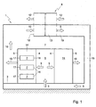
- a conditioned space 1 in a data center is shown.
- a stable temperature and air humidity prevail.
- the air humidity is between 45% and 55%.
- ICT and/or telecom equipment 2 is arranged.
- the equipment 2 produces heat and is therefore cooled using an air stream that recirculates in the space 1.
- the operating temperature of the equipment is between 20°C and 25°C.
- the space 1 is provided with a raised floor 3.
- the equipment 2 comprises for instance computer, network or server equipment and is preferably arranged in a system cabinet 14.
- system cabinets 14 are provided with a front 4 to which a cooled first air stream is supplied and a back 5 along which a heated first air stream is removed.
- the equipment 2 has a front 16 facing the front 4 of the system cabinet 14, and a back 17 facing the back 5 of the system cabinet 14.
- the system cabinets 14 have their fronts 4 facing each other, to thereby form a 'cold corridor' 6.
- the cold corridor 6 is closed off with sidewalls and a ceiling 7, to thereby create a closed space within the space 1, and to separate the heated first air completely from the cooled first air stream.
- the heated first air is cooled by means of a cooling device 8, and the cooled first air stream is thereupon blown under the raised floor 3.
- the recirculation of the first air stream in the space 1 proceeds as follows.
- a cooled first air stream 9 is blown under the raised floor 3.
- the cooled first air stream 9 is supplied to the fronts 4 of the system cabinets 14 and in them is drawn to the back 5 by the fans of the equipment 2 arranged in the system cabinets 14.
- the equipment 2 is cooled, as a result of which the cooled first air stream heats up, and the first air stream exits at the back 5 from the system cabinets 14 as a heated first air stream 10.
- the cooled first air stream 9 Upon passing through the system cabinet 14, the cooled first air stream 9 will have heated up by some 6 to 12°C, on average, thereby rendered a heated first air stream 10.
- the heated first air stream 10 is outside the cold corridor 6 and cannot mix with the cooled first air stream 9 because of the ceiling 7. As a consequence, no losses occur and the cooled first air stream 9 can be presented to the equipment 2 at the operating temperature of the equipment 2, between 20°C and 25°C.
- the cooled first air stream 9 exiting from an exit opening 19 of the cooling device 8 is thus supplied separately via a supply duct 15 to the front 16 of the equipment 2.
- the heated first air stream 10 is removed from the space 1 near the ceiling via a discharge duct, not shown, and is supplied to an inlet opening 18 of the cooling device.
- the first air stream thus recirculates in the space 1, while in this exemplary embodiment the cooled first air stream 9 is separated from the heated first air stream 10.
- the cooling device 8 is designed as an air-to-air heat exchanger 8 designed as a heat wheel, to which the heated first air stream 10 is supplied.
- the heated first air stream 10 is cooled using a separate second air stream 12.
- the second air stream 12 is supplied from outside the space 1.
- the second air stream 12 is outside air.
- the first air stream 10 and the second air stream 12 remain separate from each other, and therefore no mixing or substantially no mixing of first and second air stream takes place.
- Fig. 2 shows a schematic view of an air-to-air heat exchanger 8.
- the air-to-air heat exchanger 8 is provided with a plate-shaped heat exchange body 13, for instance a substantially metallic plate with small apertures through which air can move.
- the plate can have any shape, but is preferably rectangular or circular.
- the heat exchange body 13 may also be designed as a plate-shaped disc wound from corrugated metal plate.
- the heat exchange body 13 is rotatably arranged and moves successively through the heated first air stream 10 and the cooler second air stream 12.
- the heat exchange body 13 extends through a partition between two air chambers through which the first air stream 10, 11, and the second air stream 12, respectively, are guided.
- brushes may be provided, which prevent air being passed through the partition along with the heat wheel, so that leakage can be limited.
- a mixing chamber may be provided in the partition between the air chambers, to prevent unwanted exchange between the air streams, such as for instance moisture entry or moisture loss.
- the heat exchange body 13 moves through the heated first air stream 10
- the heat exchange body 13 is heated up and the heated first air stream 10 cools down to a cooled first air stream.
- the heated heat exchange body 13 moves through the cool incoming second air stream 12, as a result of which the second air stream 12 is heated up to a warm exiting second air stream and the heat exchange body 13 cools down.
- the heat exchange body 13 is designed as a circular thin metal wheel with small apertures through which air can move.
- An advantage of the heat wheel is that moisture transfer between the first and second air stream can be minimal, so that the air humidity of the first air stream 9, and hence the air humidity in the space 1, remains substantially unchanged.
- the construction of the heat wheel will not be discussed in more detail here, since it is well known to those skilled in the art.
- An example of the construction of a heat wheel is described in the publication 'Hoval Rotary Heat Exchanger for Heat Recovery in Ventilation Systems' HW 60aE1 11/2002 as available on www.hoval.com of Hovalwerk AG, in particular on page 8 of the publication.
- the second air stream 12 is a stream of outside air, it can for instance be used up to an inlet temperature of 18°C for complete cooling of the heated first air stream to 22°C. Since the equipment in the space in the data center needs to be cooled substantially continuously, and since the outside air temperature including nights in countries of a climate type like the Netherlands is lower than 18°C for an average 80% of the time, the heat wheel can be deployed for cooling the data center for as much as 80% of the time without additional cooling. For the residual 20% of the time, the temperature of the outside air stream will often be such that additional cooling is needed. Additional cooling can be realized with any other type of cooling device. In an environmentally friendly manner, additional cooling can for instance be carried out by means of soil storage, whereby air is drawn from a cool underground buffer space.
- a cooling device 8 for cooling the first air stream in a conditioned space 1 in a data center is needed virtually continuously - 24 hours a day, seven days a week - the use of an air-to-air heat exchanger, and in particular of a heat wheel, is extremely efficient, as no refrigerant and cooling liquid are used. Thus, a considerable saving on energy consumption and hence on electricity costs can be achieved. Also, there is less environmental impact owing to the absence of an environmentally unsound refrigerant and owing to the lower energy consumption.
- a flow rate of the first air stream 9 and the second air stream 12 will likewise remain substantially unchanged, since the cooling demand depends on the amount of heat being produced by the equipment 2.
- the flow rate of the first air stream 9, 10 can be changed. If the temperature of the incoming second air stream 12 changes, for instance due to the surroundings becoming hotter or colder, also the flow rate of the second air stream 12 can be adjusted.
- the flow rate of the second air stream 12 can be adjusted, it can be ensured that the temperature of the cooled first air stream 9 remains substantially unchanged. So, the flow rate of the second air stream 12 depends on the difference in temperature between the second air stream 12 and the first air stream 10. The flow rate can then be controlled depending on the desired temperature of the cooled first air stream, for instance 22°C. The flow rate can for instance be controlled by adjusting the rotary speed of the heat wheel. In a type of climate as in the Netherlands, the rotary speed can be low for a large part of the time.
- the heat wheel when arranged horizontally, may optionally be supported to prevent bending, for instance using support rollers.
- the cooling device may be disposed inside the space or outside it, or - as shown in Fig. 1- partly inside the space and partly outside.
- the cooling device may be disposed outside the data center. If the cooling device is disposed outside the space, the heated first air stream will for instance be carried to the air-to-air heat exchanger via a ceiling of the space.
- the additional cooling can be done in various ways, for instance by adiabatic cooling or by means of a conventional liquid cooling. Such variants will be clear to those skilled in the art and are understood to be within the scope of the invention as set forth in the appended claims.
Abstract
Description
- The invention relates to an apparatus and method for cooling a space in a data center using recirculation air, which space is air humidity-and temperature-conditioned and in which ICT and/or telecom equipment is arranged.
- Data centers are generally known and usually comprise at least one space in which ICT and/or telecom equipment is arranged, such as computer, server or network equipment. For a proper operation of the equipment, a proper and stable temperature and air humidity in the space are important. A proper operating temperature for the equipment is between about 20°C and about 25°C and a proper air humidity is between about 45% and about 55%. In view of the heat production of the ICT and/or telecom equipment, it is desirable to cool the space in order to keep the space at a stable temperature and air humidity. A data center is usually in operation 24 hours a day, seven days a week, and so the ICT and/or telecom equipment should be cooled practically continuously. The conditioned spaces in data centers are accessible to persons, and for that purpose are ventilated.
- To cool the space, it is usually provided with a raised floor under which a cold air stream is blown. Via apertures in the floor, the air stream is blown into the space. At the top of the space, the heated air stream is extracted and, after cooling, the cooled air stream is again blown under the raised floor. Thus, the air stream is recirculated in the space.
- The air stream is cooled by means of a cooling unit, usually a compression cooling unit in which a refrigerant is compressed. The heated air stream gives off its heat to the refrigerant or to a cooling liquid functioning as intermediate medium. Usually, water is utilized as intermediate medium to carry the released heat out of the space.
- The ICT and/or telecom equipment is usually placed in a system cabinet. Known system cabinets can be cooled in a vertical manner or in a horizontal manner. With cooling in a vertical manner, cold air flow is blown into the system cabinet at the bottom thereof and then, by fans, transported upwards, along the way cooling the equipment. A disadvantage is that the cold air stream heats up gradually, so that the air stream in the upper region of the system cabinet is warmer than the air stream in the lower region of the system cabinet. Due to this gradual heat-up of the air stream in the system cabinet for cooling the equipment, only a limited amount of equipment can be placed in the system cabinet, so that not the whole system cabinet can be utilized.
- With cooling in a horizontal manner, the cooled air stream is passed horizontally through the equipment arranged in the system cabinet, by means of fans of the ICT and/or telecom equipment. The heated air stream leaves the system cabinet at the back. A disadvantage is that the heated air stream of one system cabinet can mix with the cooled air stream of another system cabinet. Another disadvantage of vertical cooling is that cooled air flow can mix with heated air without cooling any equipment.
- Cooling through recirculation air an air humidity- and temperature-conditioned space in a data center in which ICT and/or telecom equipment is arranged, is not done efficiently in the known manner. Usually, the air stream is cooled to a temperature that is considerably lower than the operating temperature. Furthermore, use is made of relatively complex cooling units, and cooling involves much loss. As a consequence, much energy is required and the electricity costs of a data center are high. Especially in the case of a large data center, the costs of energy consumption consequently account for a considerable part of the total operational costs of the data center. Since the refrigerant is typically a propellant, in case of leakage of the refrigerant from the cooling unit, propellant may end up in the atmosphere, causing an environmental impact. Moreover, as a consequence of the use of water to dissipate the released heat from the space, water conduits are present in the space. These might start to leak and then constitute a danger to the ICT and/or telecom equipment arranged in the space.
-
US 6 684 653 describes the use of air-to-air heat exchangers for cooling, by means of recirculation air, shelters, cabinets and enclosures with heat generating equipment that does not require ventilation, such as electronic equipment. It is indicated that the air-to-air heat exchanger may then be of the plate- or pipe-type, and that heat exchangers of the rotary type are not used because of the difficulty in insuring that there is no leakage between the air streams. -
US 2003/005003 describes an air flow management system for an internet data center, whereby fresh cooling air is supplied to the heat generating data processes, separately via a cold corridor. -
WO 03/073012 -
US 6 004 384 describes an apparatus for removing moisture from an air or gas stream, using a rotatably arranged wheel with regenerable moisture absorbing material. - The object of the invention is to provide an apparatus of the type mentioned in the opening paragraph hereof which, while maintaining the above-mentioned advantages, can obviate the above-mentioned disadvantages.
- To that end, the invention provides an apparatus for cooling by means of recirculation air an air humidity- and temperature-conditioned space in a data center in which ICT and/or telecom equipment is arranged, wherein the apparatus comprises an air-to-air heat exchanger designed as a heat wheel, wherein recirculation air heated by the equipment is supplied as a first air stream to the air-to-air heat exchanger, and wherein the first air stream is cooled using a separate second air stream.
- The claimed invention is based on the insight that for cooling recirculation air in a data center, it is specifically a heat wheel, i.e. an air-to-air heat exchanger of the rotary type, that can be employed successfully. Precisely with the heat wheel, a sufficiently large cooling capacity can be realized for a data center, while any leakage surprisingly does not present any problems for such an application.
- In none of the cited references is the claimed invention mentioned or suggested. On the contrary,
US 6 684 653 actually points away from this invention. - By providing an air-to-air heat exchanger designed as a heat wheel, no use needs to be made anymore of a complex cooling unit with refrigerant and any intermediate medium, so that cooling is done more efficiently. This can yield a considerable saving of energy and hence of costs. Also, the environmental impact is reduced, because less energy is needed.
- Since no refrigerant is needed anymore, the environmental impact - resulting from leaking propellant - is also reduced.
- An advantage of the heat wheel as a heat exchange body is the efficient manner of heat transfer from the first air stream to the second air stream. Moreover, moisture transport between the first and the second air stream can be minimal, so that the air humidity of the first air stream remains approximately equal. For the practically continuous cooling of the recirculation air in the space in the data center, a heat wheel can be utilized in a particularly efficient manner. Further, the temperature of the cooled first air stream can be approximately equal to the operating temperature. In a region with a comparable type of climate to the Netherlands, and when using outside air flow as a second air stream, the heat wheel, at non-stop operation, can be used for nearly 80% of the time. Only for the residual 20% may the outside air stream be too warm and may limited additional cooling be needed supplemental to the cooling with the heat wheel. It is noted that within this context a heat wheel is understood to mean an air-to-air heat exchanger provided with a rotatably arranged, plate-shaped heat exchange body. The heat exchange body is preferably substantially of metal. The heat exchange body then extends preferably through a partition between two air chambers through which the first and second air stream, respectively, are guided. The heat exchange body is preferably disc-shaped and may optionally be provided with perforations. Elegantly, the heat exchange body is disposed horizontally. What can thus be achieved is that the dimensions of the heat exchange body require no greater construction height than the height of a conventional storey.
- A large cooling capacity can for instance be achieved by making the heat wheel of large design or by using a plurality of smaller heat wheels. The rotary speed of a large heat wheel can be kept low for a considerable part of the time while yet sufficient cooling capacity can be achieved and leakage can be limited.
- Preferably, the first air stream cooled by the air-to-air heat exchanger is supplied to the equipment separately from the air stream heated by the equipment. This prevents the heated first air stream from mixing with the cooling air, so that the temperature of the air stream cooled by the air-to-air heat exchanger can be approximately equal to the desired operating temperature. This yields a further saving of energy and hence of costs.
- In another advantageous embodiment, the second air stream is supplied from outside the conditioned space. This can for instance be air from another space in the data center, or outside air. By making use, for instance, of outside air, the recirculation air can be cooled in an advantageous manner.
- The invention further relates to a method for cooling by means of recirculation air an air humidity- and temperature-conditioned space in a data center in which ICT and/or telecom equipment is arranged, and to the use of a heat wheel, for cooling a recirculation air of an air humidity- and temperature-conditioned space of a data center in which ICT and/or telecom equipment is arranged. Further advantageous embodiments of the invention are represented in the subclaims. The invention will be elucidated with reference to an exemplary embodiment represented in a drawing. In the drawing:
- Fig. 1 shows a schematic view of a space with equipment;
- Fig. 2 shows a schematic view of an air-to-air heat exchanger designed as a heat wheel.
- It is noted that the figures are only schematic representations of a preferred embodiment of the invention that is described by way of non-limiting exemplary embodiment. In the figures, like or corresponding parts are designated with the same reference numerals.
- In Fig. 1 a conditioned
space 1 in a data center is shown. In thespace 1, a stable temperature and air humidity prevail. Preferably, the air humidity is between 45% and 55%. In thespace 1, ICT and/ortelecom equipment 2 is arranged. Theequipment 2 produces heat and is therefore cooled using an air stream that recirculates in thespace 1. Preferably, the operating temperature of the equipment is between 20°C and 25°C. For the purpose of the air recirculation and the cooling, thespace 1 is provided with a raisedfloor 3. - The
equipment 2 comprises for instance computer, network or server equipment and is preferably arranged in asystem cabinet 14. In this exemplary embodiment,system cabinets 14 are provided with afront 4 to which a cooled first air stream is supplied and aback 5 along which a heated first air stream is removed. Theequipment 2 has a front 16 facing thefront 4 of thesystem cabinet 14, and a back 17 facing theback 5 of thesystem cabinet 14. - To prevent heated air flow from mixing with the cooled first air stream, the
system cabinets 14 have theirfronts 4 facing each other, to thereby form a 'cold corridor' 6. In this exemplary embodiment, thecold corridor 6 is closed off with sidewalls and aceiling 7, to thereby create a closed space within thespace 1, and to separate the heated first air completely from the cooled first air stream. The heated first air is cooled by means of acooling device 8, and the cooled first air stream is thereupon blown under the raisedfloor 3. - The recirculation of the first air stream in the
space 1 proceeds as follows. A cooledfirst air stream 9 is blown under the raisedfloor 3. Adjacent thefronts 4 of thesystem cabinets 14, there are apertures in the floor through which the cooledfirst air stream 9 is blown. The cooledfirst air stream 9 is supplied to thefronts 4 of thesystem cabinets 14 and in them is drawn to theback 5 by the fans of theequipment 2 arranged in thesystem cabinets 14. On the way, theequipment 2 is cooled, as a result of which the cooled first air stream heats up, and the first air stream exits at the back 5 from thesystem cabinets 14 as a heatedfirst air stream 10. Upon passing through thesystem cabinet 14, the cooledfirst air stream 9 will have heated up by some 6 to 12°C, on average, thereby rendered a heatedfirst air stream 10. The heatedfirst air stream 10 is outside thecold corridor 6 and cannot mix with the cooledfirst air stream 9 because of theceiling 7. As a consequence, no losses occur and the cooledfirst air stream 9 can be presented to theequipment 2 at the operating temperature of theequipment 2, between 20°C and 25°C. The cooledfirst air stream 9 exiting from anexit opening 19 of thecooling device 8 is thus supplied separately via asupply duct 15 to thefront 16 of theequipment 2. The heatedfirst air stream 10 is removed from thespace 1 near the ceiling via a discharge duct, not shown, and is supplied to aninlet opening 18 of the cooling device. The first air stream thus recirculates in thespace 1, while in this exemplary embodiment the cooledfirst air stream 9 is separated from the heatedfirst air stream 10. - The
cooling device 8 is designed as an air-to-air heat exchanger 8 designed as a heat wheel, to which the heatedfirst air stream 10 is supplied. In the air-to-air heat exchanger 8, the heatedfirst air stream 10 is cooled using a separatesecond air stream 12. Preferably, as shown in Fig. 1, thesecond air stream 12 is supplied from outside thespace 1. In an advantageous embodiment, thesecond air stream 12 is outside air. In the air-to-air heat exchanger 8, thefirst air stream 10 and thesecond air stream 12 remain separate from each other, and therefore no mixing or substantially no mixing of first and second air stream takes place. - Fig. 2 shows a schematic view of an air-to-
air heat exchanger 8. The air-to-air heat exchanger 8 is provided with a plate-shapedheat exchange body 13, for instance a substantially metallic plate with small apertures through which air can move. The plate can have any shape, but is preferably rectangular or circular. Theheat exchange body 13 may also be designed as a plate-shaped disc wound from corrugated metal plate. - The
heat exchange body 13 is rotatably arranged and moves successively through the heatedfirst air stream 10 and the coolersecond air stream 12. Theheat exchange body 13 extends through a partition between two air chambers through which thefirst air stream second air stream 12, respectively, are guided. Optionally, brushes may be provided, which prevent air being passed through the partition along with the heat wheel, so that leakage can be limited. If desired, optionally, a mixing chamber may be provided in the partition between the air chambers, to prevent unwanted exchange between the air streams, such as for instance moisture entry or moisture loss. - When the
heat exchange body 13 moves through the heatedfirst air stream 10, theheat exchange body 13 is heated up and the heatedfirst air stream 10 cools down to a cooled first air stream. Next, the heatedheat exchange body 13 moves through the cool incomingsecond air stream 12, as a result of which thesecond air stream 12 is heated up to a warm exiting second air stream and theheat exchange body 13 cools down. - In a heat wheel, the
heat exchange body 13 is designed as a circular thin metal wheel with small apertures through which air can move. An advantage of the heat wheel is that moisture transfer between the first and second air stream can be minimal, so that the air humidity of thefirst air stream 9, and hence the air humidity in thespace 1, remains substantially unchanged. The construction of the heat wheel will not be discussed in more detail here, since it is well known to those skilled in the art. An example of the construction of a heat wheel is described in the publication 'Hoval Rotary Heat Exchanger for Heat Recovery in Ventilation Systems'HW 60aE1 11/2002 as available on www.hoval.com of Hovalwerk AG, in particular onpage 8 of the publication. - If the
second air stream 12 is a stream of outside air, it can for instance be used up to an inlet temperature of 18°C for complete cooling of the heated first air stream to 22°C. Since the equipment in the space in the data center needs to be cooled substantially continuously, and since the outside air temperature including nights in countries of a climate type like the Netherlands is lower than 18°C for an average 80% of the time, the heat wheel can be deployed for cooling the data center for as much as 80% of the time without additional cooling. For the residual 20% of the time, the temperature of the outside air stream will often be such that additional cooling is needed. Additional cooling can be realized with any other type of cooling device. In an environmentally friendly manner, additional cooling can for instance be carried out by means of soil storage, whereby air is drawn from a cool underground buffer space. - Since a
cooling device 8 for cooling the first air stream in a conditionedspace 1 in a data center is needed virtually continuously - 24 hours a day, seven days a week - the use of an air-to-air heat exchanger, and in particular of a heat wheel, is extremely efficient, as no refrigerant and cooling liquid are used. Thus, a considerable saving on energy consumption and hence on electricity costs can be achieved. Also, there is less environmental impact owing to the absence of an environmentally unsound refrigerant and owing to the lower energy consumption. - As long as a cooling demand is substantially unchanged - for instance in that the same amount of
equipment 2 in the space remains active - and the temperature of thesecond air stream 12 is practically unchanged, a flow rate of thefirst air stream 9 and thesecond air stream 12 will likewise remain substantially unchanged, since the cooling demand depends on the amount of heat being produced by theequipment 2. Upon a change of the cooling demand, for instance in that more orless equipment 2 in thespace 1 is active, the flow rate of thefirst air stream second air stream 12 changes, for instance due to the surroundings becoming hotter or colder, also the flow rate of thesecond air stream 12 can be adjusted. As the flow rate of thesecond air stream 12 can be adjusted, it can be ensured that the temperature of the cooledfirst air stream 9 remains substantially unchanged. So, the flow rate of thesecond air stream 12 depends on the difference in temperature between thesecond air stream 12 and thefirst air stream 10. The flow rate can then be controlled depending on the desired temperature of the cooled first air stream, for instance 22°C. The flow rate can for instance be controlled by adjusting the rotary speed of the heat wheel. In a type of climate as in the Netherlands, the rotary speed can be low for a large part of the time. - The heat wheel, when arranged horizontally, may optionally be supported to prevent bending, for instance using support rollers.
- It will be clear that the invention is not limited to the exemplary embodiments represented here. For instance, the cooling device may be disposed inside the space or outside it, or - as shown in Fig. 1- partly inside the space and partly outside. Also, the cooling device may be disposed outside the data center. If the cooling device is disposed outside the space, the heated first air stream will for instance be carried to the air-to-air heat exchanger via a ceiling of the space. The additional cooling can be done in various ways, for instance by adiabatic cooling or by means of a conventional liquid cooling. Such variants will be clear to those skilled in the art and are understood to be within the scope of the invention as set forth in the appended claims.
Claims (26)
- An apparatus for cooling by means of recirculation air an air humidity- and temperature-conditioned space in a data center in which ICT and/or telecom equipment is arranged, characterized in that the apparatus comprises an air-to-air heat exchanger designed as a heat wheel, wherein recirculation air heated by the equipment is supplied as a first air stream to the air-to-air heat exchanger, and wherein the first air stream is cooled using a separate second air stream.
- An apparatus according to claim 1, wherein the first air stream cooled by the air-to-air heat exchanger is supplied to the equipment separately from the first air stream heated by the equipment.
- An apparatus according to claim 1 or 2, wherein the second air stream is supplied from outside the conditioned space.
- An apparatus according to any one of the preceding claims, wherein the second air stream is outside air.
- An apparatus according to any one of the preceding claims, wherein the air-to-air heat exchanger is arranged outside the space.
- An apparatus according to any one of the preceding claims, wherein the air-to-air heat exchanger is arranged outside the data center.
- An apparatus according to any one of the preceding claims, wherein the heat wheel comprises a plate-shaped heat exchange body which moves successively through the first air stream and the second air stream.
- An apparatus according to claim 8, wherein the heat exchange body extends through a partition between two chambers, through which chambers the first and the second air stream, respectively, are guided.
- An apparatus according to any one of the preceding claims, wherein the cooled first air stream is introduced into the space via a floor, and the heated first air stream is removed from the space via a ceiling.
- An apparatus according to any one of the preceding claims, wherein the cooled first air stream is supplied at a front of the equipment, and the heated first air stream is removed at a back of the equipment.
- An apparatus according to any one of the preceding claims, wherein the cooled first air stream is supplied from an exit opening via a supply duct, separately from the heated first air stream, to the front of the equipment.
- An apparatus according to any one of the preceding claims, wherein the cooling apparatus is provided with an exit opening and a supply duct connected thereto which supplies the cooled first air stream, preferably as a separate air stream, to the equipment to be cooled.
- An apparatus according to any one of the preceding claims, wherein the cooling apparatus is provided with an inlet opening and a discharge duct connected thereto which discharges the heated first air stream from the space to be cooled.
- An apparatus according to any one of the preceding claims, wherein the equipment is arranged in the space in the data center with the fronts facing each other.
- An apparatus according to claim 14, wherein the fronts of the equipment are situated in a substantially closed space in the data center to which the cooled first air stream is supplied.
- An apparatus according to claim 15, wherein the heated first air stream is discharged outside the closed space, at the backs of the equipment.
- An apparatus according to any one of the preceding claims, wherein a flow rate of the first air stream is adjustable.
- An apparatus according to any one of the preceding claims, wherein the temperature of the cooled first air stream is greater than or equal to 20°C.
- An apparatus according to any one of the preceding claims, wherein the apparatus comprises an additional cooling for supplementing the cooling by means of the air-to-air heat exchanger.
- An apparatus according to claim 19, wherein the additional cooling comprises a soil storage.
- An apparatus according to claim 19, wherein the additional cooling comprises a cooling in an adiabatic manner.
- A data center, comprising an air humidity- and temperature-conditioned space where ICT and/or telecom equipment is arranged, and an apparatus which cools the space using recirculation air, the apparatus being designed according to at least one of the preceding claims.
- A method for cooling by means of recirculation air an air humidity-and temperature-conditioned space in a data center in which ICT and/or telecom equipment is arranged, wherein an air stream heated by the equipment is supplied as a first air stream to an air-to-air heat exchanger designed as a heat wheel, wherein the first air stream is cooled using a separate second air stream.
- A method for cooling a conditioned space in a data center according to claim 23, wherein, depending on a cooling demand of the equipment, the flow rate of the recirculation air is adjusted.
- A method for cooling a conditioned space in a data center according to any one of claims 22-24, wherein, depending on the temperature difference between the heated first air stream and the second air stream, a flow rate of the second air stream is adjusted.
- Use of an air-to-air heat exchanger designed as a heat wheel, for cooling recirculation air of an air humidity- and temperature-conditioned space of a data center in which ICT and/or telecom equipment is arranged.
Priority Applications (3)
| Application Number | Priority Date | Filing Date | Title |
|---|---|---|---|
| SI200830336T SI1903849T1 (en) | 2006-09-06 | 2007-09-06 | Apparatus and method for cooling a space in a data center by means of recirculation air |
| PL07115828T PL1903849T3 (en) | 2006-09-06 | 2007-09-06 | Apparatus and method for cooling a space in a data center by means of recirculation air |
| CY20111100766T CY1111998T1 (en) | 2006-09-06 | 2011-08-10 | APPLIANCE AND METHOD OF COOLING A SPACE IN A DATA CENTER THROUGH CIRCULAR AIR |
Applications Claiming Priority (1)
| Application Number | Priority Date | Filing Date | Title |
|---|---|---|---|
| NL1032450A NL1032450C2 (en) | 2006-09-06 | 2006-09-06 | Device and method for cooling a space in a data center with the aid of recirculation air. |
Publications (2)
| Publication Number | Publication Date |
|---|---|
| EP1903849A1 true EP1903849A1 (en) | 2008-03-26 |
| EP1903849B1 EP1903849B1 (en) | 2011-05-11 |
Family
ID=38051948
Family Applications (2)
| Application Number | Title | Priority Date | Filing Date |
|---|---|---|---|
| EP07808568A Withdrawn EP2082635A2 (en) | 2006-09-06 | 2007-09-06 | Apparatus and method for cooling a space in a data center by means of recirculation air |
| EP07115828A Active EP1903849B1 (en) | 2006-09-06 | 2007-09-06 | Apparatus and method for cooling a space in a data center by means of recirculation air |
Family Applications Before (1)
| Application Number | Title | Priority Date | Filing Date |
|---|---|---|---|
| EP07808568A Withdrawn EP2082635A2 (en) | 2006-09-06 | 2007-09-06 | Apparatus and method for cooling a space in a data center by means of recirculation air |
Country Status (15)
| Country | Link |
|---|---|
| US (2) | US7753766B2 (en) |
| EP (2) | EP2082635A2 (en) |
| CN (1) | CN101530016B (en) |
| AT (1) | ATE509514T1 (en) |
| AU (1) | AU2007293749B2 (en) |
| CA (1) | CA2662618C (en) |
| CY (1) | CY1111998T1 (en) |
| DK (1) | DK1903849T3 (en) |
| ES (1) | ES2366555T3 (en) |
| NL (1) | NL1032450C2 (en) |
| NZ (1) | NZ575480A (en) |
| PL (1) | PL1903849T3 (en) |
| PT (1) | PT1903849E (en) |
| SI (1) | SI1903849T1 (en) |
| WO (1) | WO2008030094A2 (en) |
Cited By (9)
| Publication number | Priority date | Publication date | Assignee | Title |
|---|---|---|---|---|
| EP2293659A3 (en) * | 2009-09-04 | 2011-07-13 | Fujitsu Limited | Data Center, Cooling System, and Method of Cooling Information Technology Device |
| WO2011121141A1 (en) | 2010-03-30 | 2011-10-06 | Advanced Shielding Technologies Europe, S.L. | System for air-conditioning the interior of a data processing center |
| WO2011160933A1 (en) * | 2010-06-25 | 2011-12-29 | International Business Machines Corporation | System, method and computer program product for controlling energy consumption in data centers |
| EP2422257A2 (en) * | 2009-04-21 | 2012-02-29 | Yahoo! Inc. | Cold row encapsulation for server farm cooling system |
| US8310829B2 (en) | 2008-05-05 | 2012-11-13 | Carrier Corporation | Integrated computer equipment container and cooling unit |
| DE202012104638U1 (en) | 2012-09-24 | 2013-02-08 | dc-ce Berlin-Brandenburg GmbH | Arrangement for conditioning a data center |
| US9204577B2 (en) | 2009-04-21 | 2015-12-01 | Yahoo! Inc. | Cold row encapsulation for server farm cooling system |
| US9363929B2 (en) | 2007-06-04 | 2016-06-07 | Yahoo! Inc. | Cold row encapsulation for server farm cooling system |
| WO2020246882A1 (en) * | 2019-06-04 | 2020-12-10 | Kievits Menzo | Data center cooling |
Families Citing this family (55)
| Publication number | Priority date | Publication date | Assignee | Title |
|---|---|---|---|---|
| NL1032450C2 (en) * | 2006-09-06 | 2008-03-07 | Uptime Technology B V | Device and method for cooling a space in a data center with the aid of recirculation air. |
| GB2444981A (en) * | 2006-12-19 | 2008-06-25 | Ove Arup & Partners Internat L | Computer cooling system |
| US9823715B1 (en) | 2007-06-14 | 2017-11-21 | Switch, Ltd. | Data center air handling unit including uninterruptable cooling fan with weighted rotor and method of using the same |
| US9693486B1 (en) | 2007-06-14 | 2017-06-27 | Switch, Ltd. | Air handling unit with a canopy thereover for use with a data center and method of using the same |
| US8523643B1 (en) | 2007-06-14 | 2013-09-03 | Switch Communications Group LLC | Electronic equipment data center or co-location facility designs and methods of making and using the same |
| US9622389B1 (en) * | 2007-06-14 | 2017-04-11 | Switch, Ltd. | Electronic equipment data center and server co-location facility configurations and method of using the same |
| US9788455B1 (en) | 2007-06-14 | 2017-10-10 | Switch, Ltd. | Electronic equipment data center or co-location facility designs and methods of making and using the same |
| US10028415B1 (en) | 2007-06-14 | 2018-07-17 | Switch, Ltd. | Electronic equipment data center and server co-location facility configurations and method of using the same |
| US9426903B1 (en) | 2008-06-27 | 2016-08-23 | Amazon Technologies, Inc. | Cooling air stack for computer equipment |
| NL1035984C (en) * | 2008-09-25 | 2010-03-26 | Boersema Installatie Adviseurs B V | COMPUTER ROOM. |
| GB2467808B (en) | 2009-06-03 | 2011-01-12 | Moduleco Ltd | Data centre |
| BE1019118A5 (en) | 2009-12-21 | 2012-03-06 | Cofely Services | UNIT, METHOD AND SYSTEM FOR TREATING AIR. |
| IT1399778B1 (en) * | 2010-03-23 | 2013-05-03 | Emerson Network Power Srl | MEANS OF COOLING AND AIR-CONDITIONING OF AN ENVIRONMENT CONTAINING A PLURALITY OF HEAT EMITTER BODIES, IN PARTICULAR FOR SALT SERVER AND SIMILAR |
| CN102375515A (en) * | 2010-08-27 | 2012-03-14 | 鸿富锦精密工业(深圳)有限公司 | Containerized data center and heat-dissipation control system thereof |
| US20120073783A1 (en) * | 2010-09-27 | 2012-03-29 | Degree Controls, Inc. | Heat exchanger for data center |
| TW201220031A (en) * | 2010-11-15 | 2012-05-16 | Hon Hai Prec Ind Co Ltd | Gas recycle device |
| US8462496B2 (en) * | 2011-02-23 | 2013-06-11 | Dell Products L.P. | System and method for a modular fluid handling system with modes in a modular data center |
| CN102116517A (en) * | 2011-03-21 | 2011-07-06 | 北京东方新旭科技发展有限公司 | Air supply control method for equipment in machine room |
| US8959941B2 (en) | 2011-07-21 | 2015-02-24 | International Business Machines Corporation | Data center cooling with an air-side economizer and liquid-cooled electronics rack(s) |
| US8955347B2 (en) | 2011-07-21 | 2015-02-17 | International Business Machines Corporation | Air-side economizer facilitating liquid-based cooling of an electronics rack |
| DE202011050979U1 (en) | 2011-08-12 | 2011-11-08 | Innovit Ag | Data Center |
| CN103930847A (en) * | 2011-10-26 | 2014-07-16 | 惠普发展公司,有限责任合伙企业 | Device for cooling an electronic component in a data center |
| EP2783556B1 (en) | 2011-11-22 | 2016-11-02 | Le Groupe S.M. Inc. | Data center cooling system |
| US8537536B1 (en) * | 2011-12-16 | 2013-09-17 | Paul F. Rembach | Rapid deployment mobile data center |
| US9429335B2 (en) | 2012-01-11 | 2016-08-30 | Hewlett Packard Enterprise Development Lp | Adiabatic cooling unit |
| DE102012001510A1 (en) | 2012-01-27 | 2013-08-01 | Bernd Schenk | Construction structure for data center, has computer-controlled mobile distributor for carrying out exchange of system components from magazine levels for controlling fixed coordinates according to program within system level |
| US9167730B2 (en) * | 2012-05-07 | 2015-10-20 | Abb Technology Oy | Electronics compartment |
| CN102946706A (en) * | 2012-10-23 | 2013-02-27 | 东南大学常州研究院 | Novel air conditioning system in machine room based on underfloor air distribution and air distribution method thereof |
| US9198331B2 (en) | 2013-03-15 | 2015-11-24 | Switch, Ltd. | Data center facility design configuration |
| GB2513147A (en) | 2013-04-17 | 2014-10-22 | Ibm | Energy efficient data center |
| KR101276380B1 (en) * | 2013-04-26 | 2013-06-18 | (주)써모텍 | Air conditioning system of data center using heat pipe and method for controlling thereof |
| JP5949655B2 (en) * | 2013-05-14 | 2016-07-13 | 株式会社北村製作所 | Radio equipment storage station |
| US9351430B2 (en) | 2013-06-13 | 2016-05-24 | Microsoft Technology Licensing, Llc | Renewable energy based datacenter cooling |
| WO2015054303A1 (en) | 2013-10-08 | 2015-04-16 | Johnson Controls Technology Company | Systems and methods for air conditioning a building using an energy recovery wheel |
| US9763363B2 (en) | 2014-01-18 | 2017-09-12 | Dyna-Tech Sales Corporation | Climate control system for data center |
| EP3158271B1 (en) | 2014-06-20 | 2021-09-22 | Nortek Air Solutions Canada, Inc. | Systems and methods for managing conditions in enclosed space |
| US9661778B1 (en) | 2014-06-27 | 2017-05-23 | Amazon Technologies, Inc. | Deployable barrier for data center |
| AU2016265882A1 (en) | 2015-05-15 | 2018-01-18 | Nortek Air Solutions Canada, Inc. | Using liquid to air membrane energy exchanger for liquid cooling |
| GB201509585D0 (en) * | 2015-06-03 | 2015-07-15 | Bripco Bvba | - |
| US11596113B2 (en) * | 2015-10-08 | 2023-03-07 | Harvest Air, LLC | Controlled agricultural system with energy wheel for treating recirculating air and method of using same |
| CN105338793A (en) * | 2015-11-17 | 2016-02-17 | 深圳市易信科技有限公司 | Container-type data center energy-saving and heat dissipation method |
| CN105451523A (en) * | 2015-12-28 | 2016-03-30 | 联想(北京)有限公司 | Heat radiator and electronic device |
| US10834855B2 (en) * | 2016-01-08 | 2020-11-10 | Nortek Air Solutions Canada, Inc. | Integrated make-up air system in 100% air recirculation system |
| EP3381248B1 (en) * | 2016-02-23 | 2023-07-26 | Hewlett Packard Enterprise Development LP | Deflection of heated air from a posterior electrical component |
| CN106061202B (en) * | 2016-06-27 | 2018-05-01 | 周丐社 | Helix cooling computer room |
| US20180077819A1 (en) | 2016-09-14 | 2018-03-15 | Switch, Ltd. | Ventilation and air flow control |
| CA3041616A1 (en) | 2016-11-11 | 2018-05-17 | Stulz Air Technology Systems, Inc. | Dual mass cooling precision system |
| KR20190119104A (en) | 2017-03-23 | 2019-10-21 | 리볼버 26 인베스트먼트 코오포레이션 | Glycol and Refrigerant Cooled Cooling Air Handling Units for Multilayer Data Centers |
| CN109688764B (en) * | 2018-12-21 | 2020-07-24 | 华为数字技术(苏州)有限公司 | Machine cabinet |
| US11041679B2 (en) * | 2019-01-21 | 2021-06-22 | Johnson Controls Technology Company | Energy recovery wheel assembly for an HVAC system |
| JP6828769B2 (en) * | 2019-05-27 | 2021-02-10 | セイコーエプソン株式会社 | projector |
| JP6874792B2 (en) * | 2019-07-19 | 2021-05-19 | セイコーエプソン株式会社 | projector |
| JP6919689B2 (en) * | 2019-09-20 | 2021-08-18 | セイコーエプソン株式会社 | projector |
| CN113047675A (en) * | 2021-03-23 | 2021-06-29 | 苏醒 | Simple transmission machine room on public green land of government |
| US11927359B2 (en) | 2021-12-03 | 2024-03-12 | Carrier Corporation | Energy recovery ventilator with bypass |
Citations (8)
| Publication number | Priority date | Publication date | Assignee | Title |
|---|---|---|---|---|
| US5238052A (en) * | 1989-08-17 | 1993-08-24 | Stirling Technology, Inc. | Air to air recouperator |
| US5649428A (en) | 1993-01-08 | 1997-07-22 | Engelhard/Icc | Hybrid air-conditioning system with improved recovery evaporator and subcool condenser coils |
| US6004384A (en) | 1998-06-03 | 1999-12-21 | Bry-Air, Inc. | Rotary adsorption apparatus |
| US6361585B1 (en) * | 1999-09-06 | 2002-03-26 | Fujitsu Limited | Rotor-type dehumidifier, starting method for rotor-type dehumidifier and an electronic device mounting the rotor-type dehumidifier |
| US20030005003A1 (en) | 1990-01-19 | 2003-01-02 | Tomoshi Hirayama | Information processing apparatus |
| US20030050003A1 (en) * | 2001-09-07 | 2003-03-13 | International Business Machines Corporation | Air flow management system for an internet data center |
| WO2003073012A1 (en) | 2002-02-27 | 2003-09-04 | Hansa Ventilatoren Und Maschinenbau Neumann Gmbh & Co. Kg | Air conditioning unit |
| US6684653B2 (en) | 2001-11-21 | 2004-02-03 | Nicholas H. Des Champs | Air-conditioner and air-to-air heat exchange for closed loop cooling |
Family Cites Families (17)
| Publication number | Priority date | Publication date | Assignee | Title |
|---|---|---|---|---|
| US4180126A (en) * | 1973-11-13 | 1979-12-25 | Gas Developments Corporation | Air conditioning apparatus and method |
| US3965695A (en) * | 1975-06-12 | 1976-06-29 | Gas Developments Corporation | Metallic sensible heat exchanger |
| JPS57124637A (en) * | 1981-01-26 | 1982-08-03 | Toshiba Corp | Air-conditioning apparatus |
| US5003961A (en) * | 1988-02-05 | 1991-04-02 | Besik Ferdinand K | Apparatus for ultra high energy efficient heating, cooling and dehumidifying of air |
| SE517219C2 (en) * | 1991-04-17 | 2002-05-07 | Bjoern Gudmundsson | Methods and apparatus for heat or mass transfer |
| US5579647A (en) * | 1993-01-08 | 1996-12-03 | Engelhard/Icc | Desiccant assisted dehumidification and cooling system |
| US20080003940A1 (en) * | 1998-11-09 | 2008-01-03 | Building Performance Equipment, Inc. | Ventilator system and method |
| US6196469B1 (en) * | 1999-07-28 | 2001-03-06 | Frederick J Pearson | Energy recycling air handling system |
| US6612365B1 (en) * | 1999-09-17 | 2003-09-02 | Matsushita Electric Industrial Co., Ltd. | Heating-element accommodating-box cooling apparatus and method of controlling the same |
| US6141979A (en) * | 1999-11-19 | 2000-11-07 | American Standard Inc. | Dual heat exchanger wheels with variable speed |
| GB0207382D0 (en) * | 2002-03-28 | 2002-05-08 | Holland Heating Uk Ltd | Computer cabinet |
| US6775997B2 (en) * | 2002-10-03 | 2004-08-17 | Hewlett-Packard Development Company, L.P. | Cooling of data centers |
| US20070125110A1 (en) * | 2005-08-17 | 2007-06-07 | Bjorn Gudmundsson | Device for transfer of heat |
| JP4816231B2 (en) * | 2005-10-07 | 2011-11-16 | 日本エクスラン工業株式会社 | Desiccant air conditioning system |
| NL1032450C2 (en) * | 2006-09-06 | 2008-03-07 | Uptime Technology B V | Device and method for cooling a space in a data center with the aid of recirculation air. |
| US20100130117A1 (en) * | 2010-01-20 | 2010-05-27 | Larsen Arthur E | Method and apparatus for data center air conditioning |
| US8974274B2 (en) * | 2010-04-16 | 2015-03-10 | Google Inc. | Evaporative induction cooling |
-
2006
- 2006-09-06 NL NL1032450A patent/NL1032450C2/en not_active IP Right Cessation
-
2007
- 2007-09-06 AT AT07115828T patent/ATE509514T1/en active
- 2007-09-06 NZ NZ575480A patent/NZ575480A/en not_active IP Right Cessation
- 2007-09-06 CN CN200780037220XA patent/CN101530016B/en active Active
- 2007-09-06 PL PL07115828T patent/PL1903849T3/en unknown
- 2007-09-06 WO PCT/NL2007/050435 patent/WO2008030094A2/en active Application Filing
- 2007-09-06 EP EP07808568A patent/EP2082635A2/en not_active Withdrawn
- 2007-09-06 AU AU2007293749A patent/AU2007293749B2/en active Active
- 2007-09-06 EP EP07115828A patent/EP1903849B1/en active Active
- 2007-09-06 SI SI200830336T patent/SI1903849T1/en unknown
- 2007-09-06 CA CA2662618A patent/CA2662618C/en active Active
- 2007-09-06 ES ES07115828T patent/ES2366555T3/en active Active
- 2007-09-06 DK DK07115828.1T patent/DK1903849T3/en active
- 2007-09-06 PT PT07115828T patent/PT1903849E/en unknown
-
2008
- 2008-05-21 US US12/124,697 patent/US7753766B2/en active Active
-
2010
- 2010-06-29 US US12/825,586 patent/US20100267325A1/en not_active Abandoned
-
2011
- 2011-08-10 CY CY20111100766T patent/CY1111998T1/en unknown
Patent Citations (8)
| Publication number | Priority date | Publication date | Assignee | Title |
|---|---|---|---|---|
| US5238052A (en) * | 1989-08-17 | 1993-08-24 | Stirling Technology, Inc. | Air to air recouperator |
| US20030005003A1 (en) | 1990-01-19 | 2003-01-02 | Tomoshi Hirayama | Information processing apparatus |
| US5649428A (en) | 1993-01-08 | 1997-07-22 | Engelhard/Icc | Hybrid air-conditioning system with improved recovery evaporator and subcool condenser coils |
| US6004384A (en) | 1998-06-03 | 1999-12-21 | Bry-Air, Inc. | Rotary adsorption apparatus |
| US6361585B1 (en) * | 1999-09-06 | 2002-03-26 | Fujitsu Limited | Rotor-type dehumidifier, starting method for rotor-type dehumidifier and an electronic device mounting the rotor-type dehumidifier |
| US20030050003A1 (en) * | 2001-09-07 | 2003-03-13 | International Business Machines Corporation | Air flow management system for an internet data center |
| US6684653B2 (en) | 2001-11-21 | 2004-02-03 | Nicholas H. Des Champs | Air-conditioner and air-to-air heat exchange for closed loop cooling |
| WO2003073012A1 (en) | 2002-02-27 | 2003-09-04 | Hansa Ventilatoren Und Maschinenbau Neumann Gmbh & Co. Kg | Air conditioning unit |
Cited By (16)
| Publication number | Priority date | Publication date | Assignee | Title |
|---|---|---|---|---|
| US9363929B2 (en) | 2007-06-04 | 2016-06-07 | Yahoo! Inc. | Cold row encapsulation for server farm cooling system |
| US8310829B2 (en) | 2008-05-05 | 2012-11-13 | Carrier Corporation | Integrated computer equipment container and cooling unit |
| EP2422257A4 (en) * | 2009-04-21 | 2014-12-31 | Yahoo Inc | Cold row encapsulation for server farm cooling system |
| EP2422257A2 (en) * | 2009-04-21 | 2012-02-29 | Yahoo! Inc. | Cold row encapsulation for server farm cooling system |
| US11212944B2 (en) | 2009-04-21 | 2021-12-28 | R2 Solutions, Llc | Cold row encapsulation for server farm cooling system |
| US10212858B2 (en) | 2009-04-21 | 2019-02-19 | Excalibur Ip, Llc | Cold row encapsulation for server farm cooling system |
| US9204577B2 (en) | 2009-04-21 | 2015-12-01 | Yahoo! Inc. | Cold row encapsulation for server farm cooling system |
| CN103605412A (en) * | 2009-04-21 | 2014-02-26 | 雅虎公司 | Cold row encapsulation for server farm cooling system |
| EP2293659A3 (en) * | 2009-09-04 | 2011-07-13 | Fujitsu Limited | Data Center, Cooling System, and Method of Cooling Information Technology Device |
| RU2542715C2 (en) * | 2010-03-30 | 2015-02-27 | Аст Модулар, С.Л. | Air conditioning system for inner space of data processing centre |
| WO2011121141A1 (en) | 2010-03-30 | 2011-10-06 | Advanced Shielding Technologies Europe, S.L. | System for air-conditioning the interior of a data processing center |
| US8532838B2 (en) | 2010-06-25 | 2013-09-10 | International Business Machines Corporation | System, method, and computer program product for controlling energy consumption in data centers |
| WO2011160933A1 (en) * | 2010-06-25 | 2011-12-29 | International Business Machines Corporation | System, method and computer program product for controlling energy consumption in data centers |
| DE202012104638U1 (en) | 2012-09-24 | 2013-02-08 | dc-ce Berlin-Brandenburg GmbH | Arrangement for conditioning a data center |
| WO2020246882A1 (en) * | 2019-06-04 | 2020-12-10 | Kievits Menzo | Data center cooling |
| NL2023261B1 (en) * | 2019-06-04 | 2020-12-11 | Kievits Menzo | Data center cooling |
Also Published As
| Publication number | Publication date |
|---|---|
| PT1903849E (en) | 2011-08-24 |
| WO2008030094A3 (en) | 2008-05-02 |
| SI1903849T1 (en) | 2011-10-28 |
| US7753766B2 (en) | 2010-07-13 |
| CA2662618A1 (en) | 2008-03-13 |
| CA2662618C (en) | 2016-05-24 |
| WO2008030094A2 (en) | 2008-03-13 |
| NZ575480A (en) | 2011-10-28 |
| NL1032450C2 (en) | 2008-03-07 |
| ATE509514T1 (en) | 2011-05-15 |
| CN101530016B (en) | 2012-02-08 |
| ES2366555T3 (en) | 2011-10-21 |
| US20100267325A1 (en) | 2010-10-21 |
| DK1903849T3 (en) | 2011-09-05 |
| PL1903849T3 (en) | 2011-10-31 |
| CY1111998T1 (en) | 2015-11-04 |
| AU2007293749B2 (en) | 2012-06-28 |
| EP2082635A2 (en) | 2009-07-29 |
| CN101530016A (en) | 2009-09-09 |
| AU2007293749A1 (en) | 2008-03-13 |
| EP1903849B1 (en) | 2011-05-11 |
| US20090073652A1 (en) | 2009-03-19 |
Similar Documents
| Publication | Publication Date | Title |
|---|---|---|
| EP1903849B1 (en) | Apparatus and method for cooling a space in a data center by means of recirculation air | |
| US7173820B2 (en) | Data center cooling | |
| EP1604263B1 (en) | Data center cooling system | |
| EP2675259B1 (en) | Hot Aisle Containment Cooling Unit and Method for Cooling | |
| US8857204B2 (en) | Real time individual electronic enclosure cooling system | |
| US7403391B2 (en) | Rack height cooling | |
| US20100051563A1 (en) | Modular data center | |
| US9476649B2 (en) | Real-time individual electronic enclosure cooling system | |
| US9781865B2 (en) | System and method of cooling and ventilating for an electronics cabinet | |
| WO2008143503A1 (en) | Data center | |
| US20150267931A1 (en) | Split air-conditioner module | |
| US10240803B2 (en) | Airfoil frame for computer room air conditioning unit |
Legal Events
| Date | Code | Title | Description |
|---|---|---|---|
| PUAI | Public reference made under article 153(3) epc to a published international application that has entered the european phase |
Free format text: ORIGINAL CODE: 0009012 |
|
| AK | Designated contracting states |
Kind code of ref document: A1 Designated state(s): AT BE BG CH CY CZ DE DK EE ES FI FR GB GR HU IE IS IT LI LT LU LV MC MT NL PL PT RO SE SI SK TR |
|
| AX | Request for extension of the european patent |
Extension state: AL BA HR MK YU |
|
| 17P | Request for examination filed |
Effective date: 20080926 |
|
| AKX | Designation fees paid |
Designated state(s): AT BE BG CH CY CZ DE DK EE ES FI FR GB GR HU IE IS IT LI LT LU LV MC MT NL PL PT RO SE SI SK TR |
|
| 17Q | First examination report despatched |
Effective date: 20081125 |
|
| RAP1 | Party data changed (applicant data changed or rights of an application transferred) |
Owner name: KYOTOCOOLING INTERNATIONAL B.V. |
|
| GRAP | Despatch of communication of intention to grant a patent |
Free format text: ORIGINAL CODE: EPIDOSNIGR1 |
|
| TPAC | Observations filed by third parties |
Free format text: ORIGINAL CODE: EPIDOSNTIPA |
|
| GRAS | Grant fee paid |
Free format text: ORIGINAL CODE: EPIDOSNIGR3 |
|
| GRAA | (expected) grant |
Free format text: ORIGINAL CODE: 0009210 |
|
| RIN1 | Information on inventor provided before grant (corrected) |
Inventor name: LODDER, ROBBERT MEES Inventor name: VAN DIJK, MARCEL Inventor name: MATSER, PEDRO Inventor name: SCHAAP, WOLTER |
|
| AK | Designated contracting states |
Kind code of ref document: B1 Designated state(s): AT BE BG CH CY CZ DE DK EE ES FI FR GB GR HU IE IS IT LI LT LU LV MC MT NL PL PT RO SE SI SK TR |
|
| REG | Reference to a national code |
Ref country code: GB Ref legal event code: FG4D |
|
| REG | Reference to a national code |
Ref country code: CH Ref legal event code: EP |
|
| REG | Reference to a national code |
Ref country code: IE Ref legal event code: FG4D |
|
| REG | Reference to a national code |
Ref country code: DE Ref legal event code: R096 Ref document number: 602007014447 Country of ref document: DE Effective date: 20110622 |
|
| REG | Reference to a national code |
Ref country code: RO Ref legal event code: EPE |
|
| REG | Reference to a national code |
Ref country code: PT Ref legal event code: SC4A Free format text: AVAILABILITY OF NATIONAL TRANSLATION Effective date: 20110809 |
|
| REG | Reference to a national code |
Ref country code: SE Ref legal event code: TRGR |
|
| REG | Reference to a national code |
Ref country code: NL Ref legal event code: T3 Ref country code: CH Ref legal event code: NV Representative=s name: PATENTANWAELTE SCHAAD, BALASS, MENZL & PARTNER AG |
|
| REG | Reference to a national code |
Ref country code: DK Ref legal event code: T3 |
|
| REG | Reference to a national code |
Ref country code: ES Ref legal event code: FG2A Ref document number: 2366555 Country of ref document: ES Kind code of ref document: T3 Effective date: 20111021 |
|
| REG | Reference to a national code |
Ref country code: GR Ref legal event code: EP Ref document number: 20110401899 Country of ref document: GR Effective date: 20110916 |
|
| REG | Reference to a national code |
Ref country code: PL Ref legal event code: T3 |
|
| REG | Reference to a national code |
Ref country code: SK Ref legal event code: T3 Ref document number: E 10065 Country of ref document: SK |
|
| REG | Reference to a national code |
Ref country code: HU Ref legal event code: AG4A Ref document number: E011900 Country of ref document: HU |
|
| PLBI | Opposition filed |
Free format text: ORIGINAL CODE: 0009260 |
|
| PLAX | Notice of opposition and request to file observation + time limit sent |
Free format text: ORIGINAL CODE: EPIDOSNOBS2 |
|
| 26 | Opposition filed |
Opponent name: MUNTERS EUROPE AB Effective date: 20120210 |
|
| REG | Reference to a national code |
Ref country code: DE Ref legal event code: R026 Ref document number: 602007014447 Country of ref document: DE Effective date: 20120210 |
|
| REG | Reference to a national code |
Ref country code: NL Ref legal event code: SEIZ Effective date: 20120606 |
|
| PLAF | Information modified related to communication of a notice of opposition and request to file observations + time limit |
Free format text: ORIGINAL CODE: EPIDOSCOBS2 |
|
| REG | Reference to a national code |
Ref country code: NL Ref legal event code: SEIC Effective date: 20120724 |
|
| PLBB | Reply of patent proprietor to notice(s) of opposition received |
Free format text: ORIGINAL CODE: EPIDOSNOBS3 |
|
| REG | Reference to a national code |
Ref country code: NL Ref legal event code: SEIZ Free format text: INDIENING CONSERVATOIR BESLAG D.D.17.05.2013 DOOR GROENEWEGEN EN PARTNERS OP VERZOEK VAN DE BESLOTEN VENNOOTSCHAP UPTIME TECHNOLGY B.V., GEVESTIGD TE SCHIPHOL-RIJK, GEMEENTE HAARLEMMERMEER EN KANTOORHOUDENDE TE DEN HOORN Effective date: 20130522 |
|
| REG | Reference to a national code |
Ref country code: NL Ref legal event code: SD Effective date: 20130605 |
|
| PLAB | Opposition data, opponent's data or that of the opponent's representative modified |
Free format text: ORIGINAL CODE: 0009299OPPO |
|
| R26 | Opposition filed (corrected) |
Opponent name: MUNTERS EUROPE AB Effective date: 20120210 |
|
| PGFP | Annual fee paid to national office [announced via postgrant information from national office to epo] |
Ref country code: TR Payment date: 20130823 Year of fee payment: 7 |
|
| PLCK | Communication despatched that opposition was rejected |
Free format text: ORIGINAL CODE: EPIDOSNREJ1 |
|
| APBM | Appeal reference recorded |
Free format text: ORIGINAL CODE: EPIDOSNREFNO |
|
| APBP | Date of receipt of notice of appeal recorded |
Free format text: ORIGINAL CODE: EPIDOSNNOA2O |
|
| APAH | Appeal reference modified |
Free format text: ORIGINAL CODE: EPIDOSCREFNO |
|
| APBQ | Date of receipt of statement of grounds of appeal recorded |
Free format text: ORIGINAL CODE: EPIDOSNNOA3O |
|
| REG | Reference to a national code |
Ref country code: FR Ref legal event code: PLFP Year of fee payment: 9 |
|
| RAP2 | Party data changed (patent owner data changed or rights of a patent transferred) |
Owner name: KYOTOCOOLING B.V. |
|
| REG | Reference to a national code |
Ref country code: NL Ref legal event code: RC Free format text: DETAILS LICENCE OR PLEDGE: PANDRECHT, GEVESTIGD, INDIENING PANDAKTE OP 10 SEPTEMBER DOOR BOEKEL DE NEREE TE AMSTERDAM. PANDGEVER IS KYOTOCOOLING B.V. TE AMERSFOORT. PANDHOUDERS ZIJN HOROS KLIMMAATTECHNIEK B.V. TE SOEST, BANENS ELECTRO B.V. TE SPAUBEEK, SLINGERLAND TECHNIEK B.V. TE AMERSFOORT EN KLINGENBURG GMBH TE GLADBECK (DE). ZIE VERDER DE AKTE. Name of requester: SLINGERLAND TECHNIEK B.V. Effective date: 20150910 |
|
| PLAB | Opposition data, opponent's data or that of the opponent's representative modified |
Free format text: ORIGINAL CODE: 0009299OPPO |
|
| R26 | Opposition filed (corrected) |
Opponent name: MUNTERS EUROPE AB Effective date: 20120210 |
|
| REG | Reference to a national code |
Ref country code: GB Ref legal event code: 732E Free format text: REGISTERED BETWEEN 20151210 AND 20151216 |
|
| REG | Reference to a national code |
Ref country code: FR Ref legal event code: GC Effective date: 20151211 |
|
| PLAB | Opposition data, opponent's data or that of the opponent's representative modified |
Free format text: ORIGINAL CODE: 0009299OPPO |
|
| PGFP | Annual fee paid to national office [announced via postgrant information from national office to epo] |
Ref country code: CY Payment date: 20150901 Year of fee payment: 9 |
|
| R26 | Opposition filed (corrected) |
Opponent name: MUNTERS EUROPE AB Effective date: 20120210 |
|
| REG | Reference to a national code |
Ref country code: DE Ref legal event code: R100 Ref document number: 602007014447 Country of ref document: DE |
|
| APBU | Appeal procedure closed |
Free format text: ORIGINAL CODE: EPIDOSNNOA9O |
|
| REG | Reference to a national code |
Ref country code: FR Ref legal event code: PLFP Year of fee payment: 10 |
|
| REG | Reference to a national code |
Ref country code: DE Ref legal event code: R081 Ref document number: 602007014447 Country of ref document: DE Owner name: KYOTOCOOLING B.V., NL Free format text: FORMER OWNER: KYOTOCOOLING INTERNATIONAL B.V., SCHIEDAM, NL Ref country code: DE Ref legal event code: R082 Ref document number: 602007014447 Country of ref document: DE Representative=s name: PATENTANWAELTE OPPERMANN & OPPERMANN, DE |
|
| PLBN | Opposition rejected |
Free format text: ORIGINAL CODE: 0009273 |
|
| STAA | Information on the status of an ep patent application or granted ep patent |
Free format text: STATUS: OPPOSITION REJECTED |
|
| 27O | Opposition rejected |
Effective date: 20160915 |
|
| PG25 | Lapsed in a contracting state [announced via postgrant information from national office to epo] |
Ref country code: CY Free format text: LAPSE BECAUSE OF NON-PAYMENT OF DUE FEES Effective date: 20160906 |
|
| PG25 | Lapsed in a contracting state [announced via postgrant information from national office to epo] |
Ref country code: TR Free format text: LAPSE BECAUSE OF NON-PAYMENT OF DUE FEES Effective date: 20140906 |
|
| REG | Reference to a national code |
Ref country code: FR Ref legal event code: PLFP Year of fee payment: 11 |
|
| REG | Reference to a national code |
Ref country code: FR Ref legal event code: PLFP Year of fee payment: 12 |
|
| REG | Reference to a national code |
Ref country code: LT Ref legal event code: MM4D Effective date: 20210906 |
|
| PG25 | Lapsed in a contracting state [announced via postgrant information from national office to epo] |
Ref country code: RO Free format text: LAPSE BECAUSE OF NON-PAYMENT OF DUE FEES Effective date: 20210906 Ref country code: MC Free format text: LAPSE BECAUSE OF NON-PAYMENT OF DUE FEES Effective date: 20210930 |
|
| REG | Reference to a national code |
Ref country code: LT Ref legal event code: NF9D Effective date: 20220531 |
|
| PGFP | Annual fee paid to national office [announced via postgrant information from national office to epo] |
Ref country code: SK Payment date: 20220831 Year of fee payment: 16 Ref country code: SE Payment date: 20220927 Year of fee payment: 16 Ref country code: RO Payment date: 20220906 Year of fee payment: 16 Ref country code: PT Payment date: 20220905 Year of fee payment: 16 Ref country code: NL Payment date: 20220926 Year of fee payment: 16 Ref country code: LU Payment date: 20220927 Year of fee payment: 16 Ref country code: LT Payment date: 20220831 Year of fee payment: 16 Ref country code: IE Payment date: 20220927 Year of fee payment: 16 Ref country code: GB Payment date: 20220927 Year of fee payment: 16 Ref country code: FI Payment date: 20220928 Year of fee payment: 16 Ref country code: EE Payment date: 20220901 Year of fee payment: 16 Ref country code: DK Payment date: 20220928 Year of fee payment: 16 Ref country code: DE Payment date: 20220928 Year of fee payment: 16 Ref country code: CZ Payment date: 20220831 Year of fee payment: 16 Ref country code: BG Payment date: 20220908 Year of fee payment: 16 Ref country code: AT Payment date: 20220901 Year of fee payment: 16 |
|
| PGFP | Annual fee paid to national office [announced via postgrant information from national office to epo] |
Ref country code: SI Payment date: 20220901 Year of fee payment: 16 Ref country code: PL Payment date: 20220923 Year of fee payment: 16 Ref country code: MC Payment date: 20220902 Year of fee payment: 16 Ref country code: LV Payment date: 20220908 Year of fee payment: 16 Ref country code: IS Payment date: 20220831 Year of fee payment: 16 Ref country code: HU Payment date: 20220910 Year of fee payment: 16 Ref country code: GR Payment date: 20220929 Year of fee payment: 16 Ref country code: FR Payment date: 20220926 Year of fee payment: 16 Ref country code: BE Payment date: 20220927 Year of fee payment: 16 |
|
| PGFP | Annual fee paid to national office [announced via postgrant information from national office to epo] |
Ref country code: IT Payment date: 20220926 Year of fee payment: 16 Ref country code: ES Payment date: 20221003 Year of fee payment: 16 |
|
| PGFP | Annual fee paid to national office [announced via postgrant information from national office to epo] |
Ref country code: CH Payment date: 20221005 Year of fee payment: 16 |
|
| PGFP | Annual fee paid to national office [announced via postgrant information from national office to epo] |
Ref country code: MT Payment date: 20220831 Year of fee payment: 16 |
|
| P01 | Opt-out of the competence of the unified patent court (upc) registered |
Effective date: 20230516 |
|
| PGFP | Annual fee paid to national office [announced via postgrant information from national office to epo] |
Ref country code: GR Payment date: 20240227 Year of fee payment: 17 |
|
| PGFP | Annual fee paid to national office [announced via postgrant information from national office to epo] |
Ref country code: IS Payment date: 20240305 Year of fee payment: 17 |
|
| PGFP | Annual fee paid to national office [announced via postgrant information from national office to epo] |
Ref country code: LT Payment date: 20240226 Year of fee payment: 17 |
|
| REG | Reference to a national code |
Ref country code: EE Ref legal event code: MM4A Ref document number: E005788 Country of ref document: EE Effective date: 20230930 |
|
| PGFP | Annual fee paid to national office [announced via postgrant information from national office to epo] |
Ref country code: NL Payment date: 20240305 Year of fee payment: 17 Ref country code: IE Payment date: 20240227 Year of fee payment: 17 |
|
| PGFP | Annual fee paid to national office [announced via postgrant information from national office to epo] |
Ref country code: AT Payment date: 20240304 Year of fee payment: 17 |
|
| REG | Reference to a national code |
Ref country code: SK Ref legal event code: MM4A Ref document number: E 10065 Country of ref document: SK Effective date: 20230906 |