EP1897512A2 - Locating an orthopaedic medical device - Google Patents
Locating an orthopaedic medical device Download PDFInfo
- Publication number
- EP1897512A2 EP1897512A2 EP07253592A EP07253592A EP1897512A2 EP 1897512 A2 EP1897512 A2 EP 1897512A2 EP 07253592 A EP07253592 A EP 07253592A EP 07253592 A EP07253592 A EP 07253592A EP 1897512 A2 EP1897512 A2 EP 1897512A2
- Authority
- EP
- European Patent Office
- Prior art keywords
- orthopaedic
- medical device
- antennae
- orthopaedic medical
- antenna
- Prior art date
- Legal status (The legal status is an assumption and is not a legal conclusion. Google has not performed a legal analysis and makes no representation as to the accuracy of the status listed.)
- Withdrawn
Links
Images


Classifications
-
- A—HUMAN NECESSITIES
- A61—MEDICAL OR VETERINARY SCIENCE; HYGIENE
- A61B—DIAGNOSIS; SURGERY; IDENTIFICATION
- A61B90/00—Instruments, implements or accessories specially adapted for surgery or diagnosis and not covered by any of the groups A61B1/00 - A61B50/00, e.g. for luxation treatment or for protecting wound edges
- A61B90/36—Image-producing devices or illumination devices not otherwise provided for
-
- A—HUMAN NECESSITIES
- A61—MEDICAL OR VETERINARY SCIENCE; HYGIENE
- A61B—DIAGNOSIS; SURGERY; IDENTIFICATION
- A61B34/00—Computer-aided surgery; Manipulators or robots specially adapted for use in surgery
- A61B34/20—Surgical navigation systems; Devices for tracking or guiding surgical instruments, e.g. for frameless stereotaxis
-
- A—HUMAN NECESSITIES
- A61—MEDICAL OR VETERINARY SCIENCE; HYGIENE
- A61B—DIAGNOSIS; SURGERY; IDENTIFICATION
- A61B90/00—Instruments, implements or accessories specially adapted for surgery or diagnosis and not covered by any of the groups A61B1/00 - A61B50/00, e.g. for luxation treatment or for protecting wound edges
- A61B90/90—Identification means for patients or instruments, e.g. tags
- A61B90/98—Identification means for patients or instruments, e.g. tags using electromagnetic means, e.g. transponders
-
- A—HUMAN NECESSITIES
- A61—MEDICAL OR VETERINARY SCIENCE; HYGIENE
- A61B—DIAGNOSIS; SURGERY; IDENTIFICATION
- A61B34/00—Computer-aided surgery; Manipulators or robots specially adapted for use in surgery
- A61B34/20—Surgical navigation systems; Devices for tracking or guiding surgical instruments, e.g. for frameless stereotaxis
- A61B2034/2046—Tracking techniques
- A61B2034/2055—Optical tracking systems
-
- A—HUMAN NECESSITIES
- A61—MEDICAL OR VETERINARY SCIENCE; HYGIENE
- A61B—DIAGNOSIS; SURGERY; IDENTIFICATION
- A61B34/00—Computer-aided surgery; Manipulators or robots specially adapted for use in surgery
- A61B34/20—Surgical navigation systems; Devices for tracking or guiding surgical instruments, e.g. for frameless stereotaxis
- A61B2034/2068—Surgical navigation systems; Devices for tracking or guiding surgical instruments, e.g. for frameless stereotaxis using pointers, e.g. pointers having reference marks for determining coordinates of body points
-
- A—HUMAN NECESSITIES
- A61—MEDICAL OR VETERINARY SCIENCE; HYGIENE
- A61B—DIAGNOSIS; SURGERY; IDENTIFICATION
- A61B90/00—Instruments, implements or accessories specially adapted for surgery or diagnosis and not covered by any of the groups A61B1/00 - A61B50/00, e.g. for luxation treatment or for protecting wound edges
- A61B90/36—Image-producing devices or illumination devices not otherwise provided for
- A61B2090/364—Correlation of different images or relation of image positions in respect to the body
- A61B2090/367—Correlation of different images or relation of image positions in respect to the body creating a 3D dataset from 2D images using position information
-
- A—HUMAN NECESSITIES
- A61—MEDICAL OR VETERINARY SCIENCE; HYGIENE
- A61B—DIAGNOSIS; SURGERY; IDENTIFICATION
- A61B90/00—Instruments, implements or accessories specially adapted for surgery or diagnosis and not covered by any of the groups A61B1/00 - A61B50/00, e.g. for luxation treatment or for protecting wound edges
- A61B90/39—Markers, e.g. radio-opaque or breast lesions markers
- A61B2090/397—Markers, e.g. radio-opaque or breast lesions markers electromagnetic other than visible, e.g. microwave
- A61B2090/3975—Markers, e.g. radio-opaque or breast lesions markers electromagnetic other than visible, e.g. microwave active
-
- A—HUMAN NECESSITIES
- A61—MEDICAL OR VETERINARY SCIENCE; HYGIENE
- A61B—DIAGNOSIS; SURGERY; IDENTIFICATION
- A61B90/00—Instruments, implements or accessories specially adapted for surgery or diagnosis and not covered by any of the groups A61B1/00 - A61B50/00, e.g. for luxation treatment or for protecting wound edges
- A61B90/39—Markers, e.g. radio-opaque or breast lesions markers
- A61B2090/3983—Reference marker arrangements for use with image guided surgery
Definitions
- This invention relates to computer assisted surgery systems for use in the performance of orthopaedic procedures.
- CAOS computer assisted orthopaedic surgery
- CAOS Computer assisted orthopaedic surgery
- CAOS Computer assisted orthopaedic surgery
- CAOS computer assisted orthopaedic surgery
- CAOS computer assisted orthopaedic surgery
- one or more fiducial markers are attached to the patent's bones, the orthopaedic implant, and/or the surgical tools. Based on the positioning of the fiducial markers, the positioning of the relevant bones, orthopaedic implant, and/or surgical tools is determined and displayed to the surgeon.
- the invention provides a computer assisted orthopaedic surgery system which includes a first orthopaedic medical device and/or a second orthopaedic medical device.
- the first orthopaedic medical device may include a first wireless transmitter.
- the first wireless transmitter may be configured to transmit a first wireless signal using a predetermined carrier frequency.
- the second orthopaedic medical device may include a second wireless transmitter that is configured to transmit a second wireless signal using the predetermined carrier frequency.
- the first orthopaedic medical device and/or the second orthopaedic medical device may be coupled to an orthopaedic implant, an orthopaedic surgical tool, and/or a bone of a patient.
- the first orthopaedic medical device may be configured to transmit the first wireless signal at a first pulse repetition frequency different from a second pulse repetition frequency used by the second wireless signal to transmit the second wireless signal.
- the first wireless signal may include a serial number of the first orthopaedic medical device.
- the second wireless signal may includes a serial number of the second orthopaedic medical device.
- the computer assisted orthopaedic surgery system may also include a plurality of antennae.
- the plurality of antennae may include a plurality of first antennae and a second antenna.
- the plurality of first antennae may each be positioned substantially coplanar with each other and the second antenna may be positioned non-coplanar with respect to the plurality of first antennae.
- the plurality of first antennae and the second antenna may be spiral directional antennae.
- the plurality of first antennae may be positioned such that a boresight of each first antenna is directed toward a common volume of space.
- the second antenna may be positioned such that a boresight of the second antenna is directed toward the common volume of space.
- the computer assisted orthopaedic surgery system may also include a controller electrically coupled to the plurality of antennae.
- the controller may be configured to receive first output signals from the plurality of antennae in response to the first wireless signal and second output signals from the plurality of antennae in response to the second wireless signal.
- the controller may also be configured to demodulate the first and second output signals.
- the controller may be configured to determine a location of the first orthopaedic medical device based on the demodulated first output signals and a location of the second orthopaedic medical device based on the demodulated second output signals.
- the controller may be configured to, for example, compare the demodulated first output signals to determine the location of the first orthopaedic medical device and compare the demodulated second output signals to determine the location of the second orthopaedic medical device.
- the controller may the location of the first and second orthopaedic medical devices by using a radio frequency direction finding algorithm.
- the computer assisted orthopaedic surgery system may includes a display device electrically coupled to the controller and the controller may be configured to display indicia of the location of the first and second orthopaedic medical devices on the display screen.
- the first and second antennae may be spiral directional antennae.
- the method may also include receiving output signals from each of the antennae in response to the modulated wireless signal and demodulating the output signals.
- the method may include determining data indicative of the location of the orthopaedic medical device based on the demodulated output signals. The data indicative of the location of the orthopaedic medical device may be determined by comparing the demodulated output signals.
- the amplitude of the demodulated output signals, the phase of the demodulated output signals, the Doppler frequency shift of the demodulated output signals, and/or the differential time of arrival of the demodulated output signals may be compared.
- the method may further include displaying indicia of the location of the orthopaedic medical device on a display device based on the determining step.
- the invention provides a method for determining a location of an orthopaedic medical device having a wireless transmitter associated therewith, the method comprising:
- the invention provides a computer assisted orthopaedic surgery system which includes an orthopaedic medical device having a wireless transmitter that is configured to transmit a modulated wireless signal.
- the modulated wireless signal may include, for example, a serial number of the orthopaedic medical device.
- the computer assisted orthopaedic surgery system may also include a plurality of first antennae, each of which is positioned substantially coplanar with each other, and a second antenna positioned non-coplanar with respect to the plurality of first antennae.
- the computer assisted orthopaedic surgery system may include a controller electrically coupled to the plurality of first antennae and the second antenna.
- the controller may be configured to receive output signals from the plurality of first antennae and the second antenna in response to the modulated wireless signal, demodulate the output signals, and determine the location of the orthopaedic medical device based on the demodulated output signals.
- the controller may determine the location of the orthopaedic medical device by, for example, using a radio frequency direction finding algorithm.
- the invention provides an implantable orthopaedic medical device for use in determining a location of a bone of a patient which includes a housing and an antenna coil positioned in the housing.
- the implantable orthopaedic medical device may also include a memory device positioned in the housing.
- the memory device may have stored therein a serial number associated with the implantable orthopaedic medical device.
- the implantable orthopaedic medical device may also include a transmitter circuit positioned in the housing and electrically coupled to the antenna coil and the memory device.
- the transmitter circuit may be configured to transmit the serial number on a predetermined carrier frequency at a predetermined pulse repetition frequency using the antenna coil.
- the implantable orthopaedic medical device may also include a switching circuit coupled to the antenna coil and the transmitter circuit.
- the switching circuit may be operable to selectively electrically connect the antenna coil to a power terminal of the transmitter circuit or an output terminal of the transmitter circuit.
- the implantable orthopaedic medical device may include a power coil electrically coupled to the transmitter circuit.
- the power coil may be configured to be inductively coupled to a power source external to the patient to supply power to the transmitter circuit.
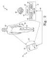
- FIG. 1 shows a computer assisted orthopaedic surgery (CAOS) system 10 which includes a computer 12 and a camera unit 14.
- the CAOS system 10 may be embodied as any type of computer assisted orthopaedic surgery system.
- the CAOS system 10 can be embodied as one or more computer assisted orthopaedic surgery systems commercially available from DePuy Orthopaedics, Inc. of Warsaw, Indiana and/or one or more computer assisted orthopaedic surgery systems commercially available from BrainLAB of Heimstetten, Germany.
- the camera unit 14 may be embodied as a mobile camera unit 16 or a fixed camera unit 18. In some embodiments, the system 10 may include both types of camera units 16, 18.
- the mobile camera unit 16 includes a stand 20 coupled with a base 22.
- the base 22 may include a number of wheels 21 to allow the mobile camera unit 16 to be repositioned within a hospital room 23.
- the mobile camera unit 16 includes a camera head 24.
- the camera head 24 includes two cameras 26.
- the camera head 24 may be positioned relative to the stand 20 such that the field of view of the cameras 26 may be adjusted.
- the fixed camera unit 18 is similar to the mobile camera unit 16 and includes a base 28, a camera head 30, and an arm 32 coupling the camera head 30 with the base 28. In some embodiments, other peripherals, such as display screens, lights, and the like, may also be coupled with the base 28.
- the camera head 30 includes two cameras 34.
- the fixed camera unit 18 may be coupled to a ceiling, as shown for example in FIG.
- the camera units 14, 16, 18 are communicatively coupled with the computer 12.
- the computer 12 may be mounted on or otherwise coupled with a cart 36 having a number of wheels 38 to allow the computer 12 to be positioned near the surgeon during the performance of the orthopaedic surgical procedure.
- FIG. 2 shows the computer 12 which includes a processor 40 and a memory device 42.
- the processor 40 may be embodied as any type of processor including, for example, discrete processing circuitry (for example a collection of logic devices), general purpose integrated circuit(s), and/or application specific integrated circuit(s) (ASICs).
- the memory device 42 may be embodied as any type of memory device and may include one or more memory types, such as, random access memory (RAM) and/or read-only memory (ROM).
- the computer 12 may include other devices and circuitry typically found in a computer for performing the functions described herein such as, for example, a hard drive, input/output circuitry, and the like.
- the computer 12 is communicatively coupled with a display device 44 via a communication link 46.
- the display device 44 may form a portion of the computer 12 in some embodiments. Additionally, in some embodiments, the display device 44 or an additional display device may be positioned away from the computer 12.
- the display device 44 may be coupled with the ceiling or wall of the operating room in which the orthopaedic surgical procedure is to be performed. Additionally or alternatively, the display device 44 may be embodied as a virtual display such as a holographic display, a body mounted display such as a heads-up display, or the like.
- the computer 12 may also be coupled with a number of input devices such as a keyboard and/or a mouse for providing data input to the computer 12.
- the display device 44 is a touch-screen display device capable of receiving inputs from an orthopaedic surgeon 50. That is, the surgeon 50 can provide input data to the computer 12, such as making a selection from a number of on-screen choices, by simply touching the screen of the display device 44.
- the computer 12 is also connected to the camera unit 16 (and/or 18) via a communication link 48.
- the communication link 48 is a wired communication link but, in some embodiments, may be embodied as a wireless communication link.
- the camera unit 16 and the computer 12 include wireless transceivers such that the computer 12 and camera unit 16 can transmit and receive data (for example image data).
- data for example image data
- the mobile camera unit 16 is shown in FIG. 2, it should be appreciated that the fixed camera unit 18 may alternatively be used or may be used in addition to the mobile camera unit 16.
- the CAOS system 10 may also include a number of sensors or sensor arrays 54 which may be coupled the relevant bones of a patient 56 and/or with orthopaedic surgical tools 58.
- a tibial array 60 includes a sensor array 62 and bone clamp 64.
- the bone clamp 64 is configured to be coupled with a tibia bone 66 of the patient 56 using a Schantz pin 68, but other types of bone clamps may be used.
- the sensor array 62 is coupled with the bone clamp 64 via an extension arm 70.
- the sensor array 62 includes a frame 72 and three reflective elements or sensors 74.
- the reflective elements 74 are embodied as spheres in the described embodiment, but may have other geometric shapes in other embodiments.
- sensor arrays having more than three reflective elements may be used.
- the reflective elements 74 are positioned in a predefined configuration that allows the computer 12 to determine the identity of the tibial array 60 based on the configuration. That is, when the tibial array 60 is positioned in a field of view 52 of the camera head 24, as shown in FIG. 2, the computer 12 is configured to determine the identity of the tibial array 60 based on the images received from the camera head 24. Additionally, based on the relative position of the reflective elements 74, the computer 12 is configured to determine the location and orientation of the tibial array 60 and, accordingly, the tibia 66 to which the array 60 is coupled.
- Sensor arrays may also be coupled to other surgical tools.
- a registration tool 80 as shown in FIG. 4, is used to register points of a bone of the patient.
- the registration tool 80 includes a sensor array 82 having three reflective elements 84 coupled with a handle 86 of the tool 80.
- the registration tool 80 also includes pointer end 88 that is used to register points of a bone.
- the reflective elements 84 are also positioned in a configuration that allows the computer 12 to determine the identity of the registration tool 80 and its relative location (that is, the location of the pointer end 88).
- sensor arrays may be used on other surgical tools such as a tibial resection jig 90, as shown in FIG. 5.
- the jig 90 includes a resection guide portion 92 that is coupled with a tibia bone 94 at a location of the bone 94 that is to be resected.
- the jig 90 includes a sensor array 96 that is coupled with the portion 92 via a frame 95.
- the sensor array 96 includes three reflective elements 98 that are positioned in a configuration that allows the computer 12 to determine the identity of the jig 90 and its relative location (for example with respect to the tibia bone 94).
- the CAOS system 10 may be used by the orthopaedic surgeon 50 to assist in any type of orthopaedic surgical procedure including, for example, a total knee replacement procedure.
- the computer 12 and/or the display device 44 are positioned within the view of the surgeon 50.
- the computer 12 may be coupled with a movable cart 36 to facilitate such positioning.
- the camera unit 16 (and/or camera unit 18) is positioned such that the field of view 52 of the camera head 24 covers the portion of a patient 56 upon which the orthopaedic surgical procedure is to be performed, as shown in FIG. 2.
- the computer 12 of the CAOS system 10 is programmed or otherwise configured to display images of the individual surgical procedure steps which form the orthopaedic surgical procedure being performed.
- the images may be graphically rendered images or graphically enhanced photographic images.
- the images may include three dimensional rendered images of the relevant anatomical portions of a patient.
- the surgeon 50 may interact with the computer 12 to display the images of the various surgical steps in sequential order.
- the surgeon may interact with the computer 12 to view previously displayed images of surgical steps, selectively view images, instruct the computer 12 to render the anatomical result of a proposed surgical step or procedure, or perform other surgical related functions:
- the surgeon may view rendered images of the resulting bone structure of different bone resection procedures.
- the CAOS system 10 provides a surgical "walk-through" for the surgeon 50 to follow while performing the orthopaedic surgical procedure.
- the surgeon 50 may also interact with the computer 12 to control various devices of the system 10.
- the surgeon 50 may interact with the system 10 to control user preferences or settings of the display device 44.
- the computer 12 may prompt the surgeon 50 for responses.
- the computer 12 may prompt the surgeon to inquire if the surgeon has completed the current surgical step, if the surgeon would like to view other images, and the like.
- the camera unit 16 and the computer 12 also cooperate to provide the surgeon with navigational data during the orthopaedic surgical procedure. That is, the computer 12 determines and displays the location of the relevant bones and the surgical tools 58 based on the data (for example images) received from the camera head 24 via the communication link 48. To do so, the computer 12 compares the image data received from each of the cameras 26 and determines the location and orientation of the bones and tools 58 based on the relative location and orientation of the sensor arrays 54, 62, 82, 96. The navigational data displayed to the surgeon 50 is continually updated. In this way, the CAOS system 10 provides visual feedback of the locations of relevant bones and surgical tools for the surgeon 50 to monitor while performing the orthopaedic surgical procedure.
- the CAOS system 10 provides visual feedback of the locations of relevant bones and surgical tools for the surgeon 50 to monitor while performing the orthopaedic surgical procedure.
- a computer assisted orthopaedic surgery (CAOS) system 100 includes a controller 102 and an antenna array 104.
- the controller 102 is electrically coupled to the antenna array 104 via a number of communication links 106.
- the communication links 106 may be embodied as any type of communication links capable of facilitating electrical communication between the controller 102 and the antenna array 104.
- the communication links may be embodied as any number of wires, cables, or the like.
- the antenna array 104 includes a number of coplanar antennae 108 and a number of non-coplanar antennae 110 (with respect to the coplanar antennae 108 as discussed in more detail below with reference to FIG. 10).
- the antennae 108, 110 are directional antennae having a radiation/receiving pattern that is not omni-directional.
- the antennae 108, 110 may be uni-directional antennae.
- the antennae 108, 110 are spiral directional antennae.
- the directivity of each directional antenna 108, 110 is defined by the beamwidth the antenna 108, 110, which is defined about the boresight of the antenna 108, 110.
- the boresight of the antenna 108, 110 typically corresponds to a physical axis of the antenna and is defined as the axis of the antenna 108, 110 along which the gain of the antenna 108, 110 is greatest.
- the antennae 108, 110 are sensitive to signals generated by sources positioned in the beamwidth of the antennae. Conversely, signals incoming toward the antennae 108, 110 from sources outside of the beamwidth of the antennae 108, 110 are substantially attenuated.
- the controller 102 includes a processor 112 and a memory device 114.
- the processor 112 may be embodied as any type of processor including, for example, discrete processing circuitry (for example a collection of logic devices), general purpose integrated circuit(s), and/or application specific integrated circuit(s) (ASICs).
- the memory device 114 may be embodied as any type of memory device and may include one or more memory types, such as, random access memory (RAM) and/or read-only memory (ROM).
- the controller 102 may include other devices and circuitry typically found in a computer for performing the functions described herein such as, for example, a hard drive, input/output circuitry, and the like.
- the controller 102 is connected to a display device 116 via a communication link 118.
- the display device 116 may form a portion of the controller 102 in some embodiments. Additionally, in some embodiments, the display device 116 or an additional display device may be positioned away from the controller 102.
- the display device 116 may be coupled to the ceiling or wall of the operating room in which the orthopaedic surgical procedure is to be performed. Additionally or alternatively, the display device 116 may be embodied as a virtual display such as a holographic display, a body mounted display such as a heads-up display, or the like.
- the controller 102 may also be coupled with a number of input devices such as a keyboard and/or a mouse for providing data input to the controller 102.
- the display device 116 is a touch-screen display device capable of receiving inputs from the orthopaedic surgeon 50 similar to the display device 44 described above with reference to FIG. 2. That is, the surgeon 50 can provide input data to the controller 102, such as making a selection from a number of on-screen choices, by simply touching the screen of the display device 116.
- the computer assisted orthopaedic surgery (CAOS) system 100 may also include a number of orthopaedic medical devices 120.
- the orthopaedic medical devices 120 may be coupled to relevant bones of the patient 56, to orthopaedic surgical tools 122, and/or to orthopaedic implants.
- the orthopaedic medical devices 120 transmit a wireless signal that is received by the antenna array 104.
- the wireless signal is a non-modulated wireless signal of a predetermined frequency.
- each orthopaedic medical device 120 may transmit a wireless signal (for example a non-modulated wireless signal) at a different frequency with respect to each other.
- each orthopaedic medical device 120 may transmit a wireless signal at different pulse repetition frequencies (PRF). That is, each orthopaedic medical device 120 may be configured to transmit a wireless signal having pulses of the same carrier frequency but at different repetition rates.
- PRF pulse repetition frequencies
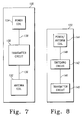
- FIG. 7 shows an orthopaedic medical device 120 which includes a transmitter circuit 130, an antenna coil 132, and a power coil 134.
- the transmitter circuit 130 is connected to the antenna coil 132 via a number of communication links 136 and to the power coil 134 via a number of communication links 138.
- the communication links 136, 138 may be embodied as any type of communication link capable of facilitating communication between the transmitter circuit 130 and the antenna coil 132 and power coil 134, respectively.
- the communication links 136, 138 may be embodied as wires, cables, printed circuit board (PCB) traces, fibre optic cables, or the like.
- the transmitter circuit 130 may be embodied as or include any type of transmitter circuitry capable of generating a wireless signal at a predetermined frequency.
- the transmitter circuit 130 may be embodied as a simple inductor-capacitor (LC) circuit or a crystal oscillator circuit and associated circuitry.
- LC inductor-capacitor
- the transmitter circuit 130 may be configured to transmit a wireless signal at a predetermined frequency or a predetermined pulse repetition frequency.
- the wireless signal generated by the transmitter circuit 130 is a non-modulated wireless signal. That is, the wireless signal does not include other signals (for example data signals) embedded or modulated in the predetermined carrier frequency.
- the predetermined frequency of the wireless signal may be any frequency receivable by the antenna array 104.
- the transmitter circuit 130 is configured to transmit wireless signals in the very-high frequency (VHF) band or ultra-high frequency (UHF) band. Because the orthopaedic medical device 120 of FIG.
- the overall size of the orthopaedic medical device 120 may be reduced compared to typical orthopaedic medical devices used for determining the location of patient's bones, orthopaedic implants, or orthopaedic surgical tools. Such reduction in the size of the orthopaedic medical device 120 may improve the orthopaedic surgical procedure by allowing, for example, smaller access incisions in the patient 50.
- the transmitter circuit 130 receives power via the power coil 134.
- the power coil 134 is configured to be inductively coupled to a power source (not shown) external to the patient.
- the power coil 134 may include any number of individual coils.
- the power coil 134 may include a single coil that is inductively coupled to the external power source by positioning the external power source near the skin of the patient such that the power coil 134 lies within an alternating current (AC) magnetic field generated by the external power source.
- AC alternating current
- the power coil 134 includes more than a single coil to thereby improve the inductive coupling of the power coil 134 and the external power source.
- the power coil 134 is embodied as three separate coils positioned orthogonally with respect to each other.
- the external power source may be embodied as any type of power source capable of inductively coupling with the power coil 134 and generating a current therein.
- the external power source includes two patches which can be provided on the skin of the patient in the vicinity of the orthopaedic medical device 120. The patches each include a Helmholtz-like coil and are powered such that the Helmholtz coils produce an isotropic magnetic field, which is received by the power coil 134.
- the orthopaedic medical device 120 includes a transmitter circuit 140, a switching circuit 142, and a power/antenna coil 144.
- the transmitter circuit 140 is communicatively coupled to the switching circuit 142 via a number of communication links 146.
- the switching circuit 142 is coupled to the power/antenna coil 144 via a number of communication links 148.
- the communication links 146, 148 may be embodied as any type of communication link capable of facilitating communication between the transmitter circuit 140, the switching circuit 142, and the power coil 134.
- the communication links 146, 148 may be embodied as wires, cables, printed circuit board (PCB) traces, fibre optic cables, or the like.
- the transmitter circuit 140 is substantially similar to the transmitter 130 described above with reference to FIG. 7 and, as such, may be embodied as or include any type of transmitter circuit capable of transmitting a wireless signal via the power/antenna coil 132.
- the transmitter circuit 140 may be embodied as a simple inductor-capacitor (LC) circuit or a crystal oscillator circuit and associated circuitry.
- the transmitter circuit 140 may be configured to transmit a wireless signal at a predetermined frequency or a predetermined pulse repetition frequency.
- the wireless signal generated by the transmitter circuit 140 is a non-modulated wireless signal.
- the transmitter circuit 130 is configured to transmit wireless signals in the very-high frequency (VHF) band or ultra-high frequency (UHF) band.
- VHF very-high frequency
- UHF ultra-high frequency
- the transmitter circuit 140 receives power and transmits a wireless signal using the same coil, the power/antenna coil 144.
- the switching circuit 142 is operable to connect the power/antenna coil 144 to a power terminal(s) or port of the transmitter circuit 140 when power is to be provided thereto and to connect the power/antenna coil 144 to an output terminal(s) or port of the transmitter circuit 140 when power is not being provided and transmission of the wireless signal is desired.
- the switching circuit 142 may include a coil or other device responsive to the magnetic field generated by the external power source to switch the connection of the power/antenna coil 144 from the output terminal of the transmitter circuit to the power terminal.
- the orthopaedic medical device 120 may also include an internal power source (not shown), such as a battery, that is connected to the transmitter circuit 140 to provide power thereto.
- the orthopaedic medical device 120 includes an internal power source (not shown).
- the internal power source may be embodied as, for example, a battery or the like and electrically coupled to the transmitter circuit 130, 140 to provide power thereto.
- a separate power coil for example power coil 134.
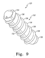
- the orthopaedic medical device 120 may include a housing 150 configured to be implanted into the bone as shown in FIG. 9.
- the circuitry associated with the medical device 120 (that is, the transmitter coils 130, 40, the antenna and/or power coils 132, 134, 144, etc.) is positioned in an inner cavity (not shown) of the housing 150.
- the housing 150 includes a body 152, a cap 154 configured to be coupled to the body 152, and a number of threads 156 defined about the body 152.
- the housing 150 may be attached to the bone of the patient by first drilling a pilot hole into the bone using a suitable orthopaedic surgical drill or the like and subsequently screwing the housing 150 into the hole created by the surgical drill.
- the housing 150 is only one example of a housing which is capable of being coupled to a bone of a patient and that in other embodiments other housings having various configurations may be used.
- a press-fit housing may be used. Press-fit housings are typically devoid of any threads and are configured to be pressed into a hole or cavity that has been drilled or formed into the bone.
- other types of housings may be used in embodiments in which the orthopaedic medical device 120 is coupled to an orthopaedic implant or an orthopaedic surgical tool.
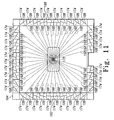
- FIG. 10 shows the antenna array 104 incorporated into an orthopaedic surgery operating room 160.
- the antennae 108 of the antenna array 104 are coupled to one or more walls of the operating room 160 coplanar with each other so as to define a reference plane.
- the antennae 108 are coupled to the walls 162, 164, 166 such that the boresight 168 of each antenna 108 is directed toward a common volume of space 170 of the operating room 160 in which the orthopaedic surgery procedure is to be performed.
- the patient 56 or relevant portion of the patient 56 is positioned within the common volume 170.
- the antennae 108 may be coupled to the walls 162, 164, 166 such that the boresight 168 of each antenna 108 is directed toward an orthopaedic operating table 172 positioned in the operating room 160.
- the walls 162, 164, 166 may include recesses 174 in which the antennae 108 are positioned.
- the antennae 108 located farther from the center area of the associated wall 162, 164, 166 are angled to a greater degree than the antennae 108 located toward the center area of the associated wall 162, 164, 166 such that the boresight 168 of each antenna 108 is directed toward the common volume 170 and/or operating table 172.
- a radio frequency permeable window or panel 174 is coupled to the walls 162, 164, 166 in front of the antennae 108 such that the antennae 108 are hidden from view as shown in FIG. 10.
- the antennae 108 are more sensitive to wireless signals transmitted from sources positioned in the common volume 170 and less sensitive to wireless signals transmitted from sources positioned outside of the common volume 170.
- the antennae 110 of the antenna array 104 are coupled to a support structure 180 secured to a ceiling of the operating room 160 via a number of support arms 182.
- the antennae 110 are positioned such that the antennae 110 are non-coplanar with respect to the antennae 108.
- the antennae 110 are coupled to the support structure 180 such that each antenna 110 is directed toward the common volume of space 170.
- the antennae 110 may be coupled to the support structure 180 or otherwise positioned such that a boresight of each antenna 110 is directed to the common volume of space 170. To do so, the antennae 110 may be coupled to an inner side 184 of the support structure 180.
- each of the antennae 110 may be positioned so as to be directed to the common volume of space 170 and/or operating table 172.
- the support structure 180 includes a number of recesses defined in the inner side 184.
- the antennae 110 may be positioned therein and a radio frequency permeable window or panel 186 may be secured to the support structure 180 in front of the antennae 110.
- the support structure 180 may be of any configuration that facilitates the directing of the antennae 110 toward the common volume of space 170 and/or operating table 172.
- the inner side 184 of the support structure 180 may be configured to extend outwardly in a downward direction such that each antenna 110 coupled to the inner side 184 of the support structure is directed downwardly toward the common volume of space 170 and/or operating table 172.
- the support structure 180 has a cross-section shaped approximately so that it has the shape of a parallelogram, such that the inner side 184 extends outwardly in the downward direction.
- the antennae 110 coupled to the inner side 184 of the support structure 180 are each angled toward the common volume of space 170.
- FIG. 1 As shown in FIG.
- the support structure 180 has a substantially trapezoidal cross-section such that the inner side 184 extends outwardly in the downward direction.
- the antennae 110 coupled to the inner side 184 of the support structure 180 of FIG. 13 are each angled toward the common volume of space 170.
- the antenna array 104 may have more or less antennae 108, 110 in other embodiments.
- the antenna array 104 may include only three antennae 108 positioned coplanar with respect to each other so as to define a reference plane.
- the antenna array 104 may include only one antenna 110 positioned non-coplanar with respect to the antennae 108.
- an amount of redundancy is provided.
- the controller 102 may still receive output signals from other non-obscured antennae 108, 110.
- the controller 102 can thereby still determine the location of the orthopaedic medical device 120 as discussed in more detail below with reference to FIG. 14.
- the antennae 108, 110 are shown in FIGS. 10 to 13 as being coupled to the walls 162, 164, 166 and ceiling of the orthopaedic surgery operating room, in other embodiments, the antennae 108, 110 may be coupled to movable support structures similar to, for example, the stand 20 in and described above with reference to FIG.
- the antennae 108, 110 may be moved about the operating room to avoid obstruction of the wireless signal. Additionally, the antennae 108, 110 may be transported between and used in different operating rooms. However, it should be noted, that in such embodiments, the antennae 108 are positioned such that each antenna 108 is coplanar with respect to each other and that the antennae 110 are positioned non-coplanar with respect to the antennae 108.
- a surgeon may use the computer assisted orthopaedic surgery (CAOS) system 100 to track the location of the orthopaedic medical device(s) 120 and, thereby, the location of the patient's relevant bone(s), orthopaedic implant, and/or orthopaedic surgical tool 122 coupled thereto.
- the computer assisted orthopaedic surgery (CAOS) system 100 and/or the controller 102 may execute an algorithm 200 for determining the location of the orthopaedic medical device 120 and any associated structure coupled thereto.
- the algorithm 200, or portions thereof, may be embodied as software/firmware code stored in, for example, the memory device 114.
- the algorithm 200 begins with a process step 202 in which the wireless signal(s) transmitted by the orthopaedic medical device(s) 120 are received by the antennae 108, 110.
- a large number of antennae 108, 110 may be used in some embodiments to provide an amount of redundancy and improve the calculation of the location of the orthopaedic medical device(s) 120.
- the controller 102 receives the output signals of each of the antennae 108, 110 via the communication link 106.
- the controller 102 determines data indicative of the location of the orthopaedic medical device 120 based on the output signals received from the antennae 108, 110. Because each of the antennae 108, 110 is positioned at a different location with respect to the orthopaedic medical device 120, the output signals received from each antenna 108, 110 are different to varying amounts. As such, the location of the orthopaedic medical device 120 may be determined by comparing a portion or all of the output signals received form the antennae 108, 110. To do so, the controller 102 may execute a radio frequency direction finding algorithm. The controller 102 may use any radio frequency direction finding algorithm capable of determining data indicative of the location of the orthopaedic medical device 120 based on the output signals.
- the controller 102 may determine the location of the orthopaedic medical device 120 by comparing or otherwise analysing the amplitudes of the various output signals, the phase of the output signals, the Doppler frequency shift of the output signals, the differential time of arrival of the output signals, and/or any other radio frequency direction finding methodology usable to determine the location of the orthopaedic medical device 120.
- the location of the orthopaedic medical device 120 is determined in process step 208.
- the location of the structure for example patient's bone(s), orthopaedic implant, orthopaedic surgical tool, etc.
- the controller 102 may use any registration method.
- a registration tool similar to registration tool 80 is used to register the patient's bone, the orthopaedic implant, and/or the surgical tool to the controller 102.
- pre-operative images of the patient's relevant bones, the orthopaedic implant, and/or the surgical tool having indicia of the implanted orthopaedic medical device(s) 120 are used. Based on such pre-operative images and the determined location of the orthopaedic medical device 120, the controller 102 may determine the location of the relevant bone of the patient. Subsequently in process step 210, the controller 102 displays indicia of the location of the relevant bone(s) of the patient on the display device 116.
- the controller 102 may display a rendered image of the patient bone on the display device 116 in a location as determined in process step 208.
- the controller 102 may execute an appropriate two dimensional-to-three dimensional morphing algorithm to transform the two-dimensional image of the patient's bone to a three-dimensional image and display such three-dimensional image to the surgeon 50 on the display device 116 based on the determined location of the bone.
- a system 300 for monitoring kinematic motion of a patient includes a patient exercise machine 302, an antenna array 304 coupled to the patient exercise machine 302, a controller 314, and a display device 316.
- the patient exercise machine 302 may be embodied as any type of exercise machine on which the patient may exercise and via which an orthopaedic surgeon or healthcare provider may observe the kinematic motion of the patient.
- the patient exercise machine 302 may be embodied as a treadmill, a stairstepper machine, a stationary bicycle, an elliptical trainer, a rowing machine, a ski machine, or the like.
- the antenna array 304 includes a first antenna 306, a second antenna 308, and a third antenna 310 coupled to the patient exercise machine 302 such that each of the antennae 306, 308, 310 is coplanar with each other.
- the antenna array 304 also includes a fourth antenna 312 coupled to the patient exercise machine 302 such that the fourth antenna 312 is non-coplanar with respect to the antennae 306, 308, 310.
- the antennae 306, 308, 310, 312 are directional antennae such as, for example, spiral directional antennae.
- the antennae 306, 308, 310, 312 are positioned such that each of the antennae 306, 308, 310, 312 is directed toward the patient exercise machine 302 and, more specifically, toward a volume of space occupied by the relevant portion of the patient when the patient is exercising on the patient exercise machine 302.
- the antennae 306, 308, 310 may be positioned such that the boresights of the antennae 306, 308, 310 define a reference plane.
- the antenna 312 may be positioned off of but directed toward the reference plane such that the boresight of the antenna 312 intersects the reference plane defined by the antennae 306, 308, 310.
- FIG. 17 shows a patient exercise machine 302 in the form of a treadmill 400.
- the coplanar antennae 306, 308, 310, 312 are coupled to the treadmill 400.
- the antennae 306, 308, 310, 312 are positioned in housings 404, 406, 408, 410, respectively, which are coupled to a frame 402 of the treadmill 400. That is, the first housing 404, and thereby the coplanar antenna 306, is coupled to the frame 402 of the treadmill 400 on a first longitudinal side 412.
- the second housing 406, and thereby the coplanar antenna 308, is coupled to the frame 402 on a second longitudinal side 414 of the treadmill 400.
- the third housing, and thereby the coplanar antenna 308, is coupled to the frame 402 on a front side 416 of the treadmill 400.
- the housings 404, 406, 408 are coupled to the frame 402 such that the antennae 306, 308, 310 are positioned coplanar with respect to each other.
- the antennae are positioned such that the boresight of each antenna 306, 308, 310 is directed inwardly toward the patient exercise machine 302. That is, the antenna 306 is positioned such that the boresight of the antenna 306 is directed toward the opposite longitudinal side 414 of the treadmill.
- the antenna 308 is positioned such that the boresight of the antenna 308 is directed toward the opposite longitudinal side 412.
- the antenna 310 is positioned such that the boresight of the antenna 310 is directed toward a rear side 418 of the treadmill 400.
- the beamwidths of the antennae 302, 308, 310 define a common volume of space in which the relevant portion(s) of the patient is positioned when the patient is exercising on the treadmill 400. For example, if the relevant portion of the patient is a knee area, the antennae 302, 308, 310 are positioned such that the relevant knee and surrounding area of the patient is positioned in the common volume of space defined by the beamwidths of the antennae 302, 308, 310.
- the housings 404, 406, 408 are movably coupled to the frame 402 such that the housings 404, 406, 408 may be moved to different positions to thereby move the common volume of space such that the relevant portion of the patient is positioned therein.
- the housings 404, 406, 408 may be movably coupled to the frame 402 such that the housings 404, 406 408 may be moved vertically up or down as required based on the particular orthopaedic surgical procedure being performed and the geometries of the patient.
- the housing 410 is coupled to the frame 402 such that the antenna 312 is positioned non-coplanar with respect to the antennae 306, 308, 310 but is directed toward the reference plane defined by the antennae 306, 308, 310. That is, the antenna 312 is coupled to the frame 402 such that the beamwidth of the antenna 312 is directed toward the common volume of space defined by the beamwidths of the antennae 306, 308, 310. Similar to the housings 404, 406, 408, the housing 410 may be movably coupled to the frame 402 such that the housing 410 may be moved to different positions to thereby move the common volume of space such that the relevant portion of the patient is positioned therein.
- FIG. 18 shows a patient exercise machine 302 in the form of a stairstepper 500.
- the coplanar antennae 306, 308, 310, 312 are positioned in housings 504, 506, 508, 510, respectively, which are coupled to a frame 402 of the stairstepper 500 in a similar manner as described above with reference to the treadmill 400. That is, the first housing 504, and thereby the coplanar antenna 306, is coupled to the frame 502 of the stairstepper 500 on a first longitudinal side 512. The second housing 506, and thereby the coplanar antenna 308, is coupled to the frame 502 on a second longitudinal side 514 of the stairstepper 500.
- the third housing 310, and thereby the coplanar antenna 308, is coupled to the frame 502 on a front side 516 of the stairstepper 500.
- the housings 504, 506, 508 are coupled to the frame 502 such that the antennae 306, 308, 310 are positioned coplanar with respect to each other and the boresight of each antenna 306, 308, 310 is directed inwardly toward the patient exercise machine 302 as described above in relation to the treadmill 500. That is, the antenna 306 is positioned such that the boresight of the antenna 306 is directed toward the opposite longitudinal side 514 of the stairstepper 500.
- the antenna 308 is positioned such that the boresight of the antenna 308 is directed toward the opposite longitudinal side 512 and the antenna 310 is positioned such that the boresight of the antenna 310 is directed toward a rear side 518 of the stairstepper 500.
- the beamwidths of the antennae 302, 308, 310 define a common volume of space in which the relevant portion(s) of the patient is positioned when the patient is exercising on the stairstepper 500.
- the housings 504, 506, 508 may be movably coupled to the frame 502 such that the housings 404, 406, 408 may be moved to different positions to thereby move the common volume of space such that the relevant portion of the patient is positioned therein.
- the housing 510 is coupled to the frame 502 such that the antenna 312 is positioned non-coplanar with respect to the antennae 306, 308, 310 but is directed toward the reference plane defined by the antennae 306, 308, 310. That is, the antenna 312 is coupled to the frame 502 such that the beamwidth of the antenna 312 is directed toward the common volume of space defined by the beamwidths of the antennae 306, 308, 310. Similar to the housings 504, 506, 508, the housing 510 may be movably coupled to the frame 502 such that the housing 510 may be moved to different positions to thereby move the common volume of space such that the relevant portion of the patient is positioned therein.
- the controller 314 includes a processor 318 and a memory device 320.
- the processor 314 may be embodied as any type of processor including, for example, discrete processing circuitry (for example a collection of logic devices), general purpose integrated circuit(s), and/or application specific integrated circuit(s) (ASICs).
- the memory device 320 may be embodied as any type of memory device and may include one or more memory types, such as, random access memory (RAM) and/or read-only memory (ROM).
- the controller 314 may include other devices and circuitry typically found in a computer for performing the functions described herein such as, for example, a hard drive, input/output circuitry, and the like.
- the controller 314 is connected to the antenna array 304 via a number of communication links 322.
- the communication links 322 may be embodied as any type of communication links capable of facilitating electrical communication between the controller 314 and the antenna array 304.
- the communication links may be embodied as any number of wires, cables, or the like.
- the controller 314 is also communicatively coupled with a display device 316 via a communication link 324. Although shown in FIG. 15 as separate from the controller 314, the display device 316 may form a portion of the controller 314 in some embodiments. Additionally, in some embodiments, the display device 316 or an additional display device may be positioned away from the controller 314.
- the display device 316 may be embodied as a virtual display such as a holographic display, a body mounted display such as a heads-up display, or the like.
- the controller 314 may also be coupled with a number of input devices such as a keyboard and/or a mouse for providing data input to the controller 314.
- the display device 316 is a touch-screen display device capable of receiving inputs from the orthopaedic surgeon 50 similar to the display device 44 described above with reference to FIG. 2. That is, the surgeon 50 can provide input data to the controller 314, such as making a selection from a number of on-screen choices, by simply touching the screen of the display device 316.
- a surgeon may use the system 300 to track the location of the orthopaedic medical device(s) 120 and, thereby, the location of the patient's relevant bone(s) and/or orthopaedic implant.
- the system 300 and/or the controller 314 may execute an algorithm 350 for monitoring the kinematic motion of a patient as defined by the motion of relevant bones of the patient.
- the algorithm 350 may be embodied as software/firmware code stored in, for example, the memory device 320.
- the algorithm 350 begins with a process step 352 in which the wireless signal(s) transmitted by the orthopaedic medical device(s) 120 are received by the antennae 306, 308, 310, 312 while the patient is exercising on the patient exercise machine 302.
- the orthopaedic medical device(s) 120 may be powered by an external transcutaneous power source such as an external primary coil or by an internal power source such as a battery or the like.
- the controller 314 After the wireless signal(s) transmitted by the orthopaedic medical device(s) 120 are received by the antennae 306, 308, 310, 312, the controller 314 receives the output signals of each of the antennae 306, 308, 310, 312 via the communication links 322 in process step 354. Next, in process step 356, the controller 314 determines data indicative of the location of the orthopaedic medical device(s) 120 based on the output signals received from the antennae 306, 308, 310, 312. Because each of the antennae 108, 110 is positioned at a different location with respect to the orthopaedic medical device 120, the output signals received from each antenna 306, 308, 310, 312 are different to varying amounts.
- the location of the orthopaedic medical device 120 may be determined by comparing the output signals received from the antennae 306, 308, 310, 312. To do so, similar to the controller 102 described above with reference to FIG. 6, the controller 314 may execute a radio frequency direction finding algorithm. The controller 314 may use any radio frequency direction finding algorithm capable of determining data indicative of the location of the orthopaedic medical device 120 based on the output signals.
- the controller 314 may determine the location of the orthopaedic medical device 120 by comparing or otherwise analysing the amplitudes of the various output signals, the phase of the output signals, the Doppler frequency shift of the output signals, the differential time of arrival of the output signals, and/or any other radio frequency direction finding methodology usable to determine the location of the orthopaedic medical device 120.
- the controller 314 may use, for example, pre-operative images and/or post-operative images of the patient's relevant bones having indicia of the implanted orthopaedic medical device 120. Based on such pre-operative images and the determined location of the orthopaedic medical device 120, the controller 314 may determine the location of the relevant bone of the patient. Subsequently in process step 360, the controller 314 displays indicia of the location of the relevant bone(s) of the patient on the display device 316.
- the controller 314 may display a rendered image of the patient bone on the display device 316 in a location as determined in process step 358.
- the controller 314 may be configured to display line segments indicative of the relative positions of the patient's bone(s).
- the controller 314 may be configured to store the location data in a storage device (not shown) or the memory device 320 such that the data may be retrieved at a later time and view in sequential animation such that the range of kinematics motion of the patient may be viewed via the display device 316.
- the system 300 may be used to monitor the pre-operative and/or post-operative kinematic motion of the patient.
- one or more orthopaedic medical devices 120 may be implanted into the relevant bones of the patient.
- the pre-operative kinematic motion the patient may then be determined using the system 300 and algorithm 350.
- the sequential location data of the patient's bones may then be stored.
- the orthopaedic surgical procedure may subsequently be performed and the post-operative kinematic motion of the patient may be determined using the system 300.
- the surgeon or other healthcare provided may comparatively view the kinematic motion of the patient and, thereby, determine the success or quality of the orthopaedic surgical procedure, as well as, identify any possible orthopaedic problems which the patient may encounter.
- the kinematic motion of the patient may be post-operatively determined over a period of time such that the "wear" of an orthopaedic implant may be determined and possibly corrected for in further orthopaedic surgical procedures.
- any number of orthopaedic medical devices 120 may be used.
- two or more orthopaedic medical devices 120 may be coupled to the relevant patient's bone, orthopaedic implant, or surgical tool.
- the location and orientation of the patient's bone, orthopaedic implant, and/or surgical tool may be determined based on the wireless signals transmitted from the plurality of orthopaedic medical devices 120.
- three orthopaedic medical devices 120 may be coupled to the relevant patient's bone, orthopaedic implant, or surgical tool.
- the six degrees of freedom of the patient's bone, orthopaedic implant, or surgical tool may be determined based on the wireless signals transmitted from the three orthopaedic medical devices 120. However, it should be appreciated that the six degrees of freedom of the relevant patient's bone, orthopaedic implant, and/or surgical tool may be determined using more or less orthopaedic medical devices 120.
- the computer assisted orthopaedic surgery (CAOS) system 100 and/or the system 300 may include any number of orthopaedic medical devices 120 in some embodiments.
- the orthopaedic medical devices 120 are embodied as the devices 120 described above with reference to FIGS. 7 and 8, the orthopaedic medical devices 120 are configured to transmit non-modulated wireless signals using different frequencies.
- each of the orthopaedic medical devices 120 may be configured to transmit a modulated signal using the same carrier frequency.
- the orthopaedic medical devices 120 transmit a serial number associated with each respective device 120.
- the orthopaedic medical device(s) 120 can include a transmitter circuit 600, an antenna coil 602, a memory device 604, and a power coil 606.
- the transmitter circuit 600 is communicatively coupled to the antenna coil 602 via a number of communication links 608, to the memory device 604 via a number of communication links 610, and to the power coil 606 via a number of communication links 612.
- the communication links 608, 610, 612 may be embodied as any type of communication links capable of facilitating communication between the transmitter circuit 600 and the antenna coil 602, the memory device 604, and the power coil 606, respectively.
- the communication links 608, 610, 612 may be embodied as wires, cables, printed circuit board (PCB) traces, fiber optic cables, or the like.
- the transmitter circuit 600 may be embodied as or include any type of transmitter circuitry capable of generating a modulated wireless signal using a predetermined carrier frequency.
- the transmitter circuit 600 may include a simple inductor-capacitor (LC) circuit or a crystal oscillator circuit and associated circuitry.
- the transmitter circuit 600 includes circuitry for accessing data stored in the memory device 604.
- the memory device 604 may be embodied as any type of memory device and may include one or more memory types, such as, random access memory (RAM) and/or read-only memory (ROM).
- the memory device 604 has stored therein and/or is capable of storing a serial number associated with the respective orthopaedic medical device 120.
- the serial number may be embodied as any type of data that uniquely identifies the respective orthopaedic medical device 120 from other orthopaedic medical devices 120 being used in the relevant orthopaedic medical procedure.
- an error correction code (ECC) associated with the serial number may also be stored in the memory device 120 such that the respective serial number may be validated by the controller 102/control circuit 314.
- the transmitter circuit 600 may include additional processing circuitry capable of determining the error correction code from the serial number such that it is not required to store the error correction code in the memory device 120 prior to transmission of the serial number.
- the error correction code may be embodied as any type of data capable of providing validation of the accuracy of the serial number once received by the controller 102/control circuit 314.
- the error correction code may be embodied as, for example, a checksum or a cyclic redundancy check value or data.
- the transmitter circuit 600 is configured to retrieve the serial number from the memory device 604 via the communication link 610. In addition, the transmitter circuit 600 retrieves the error correction code from the memory device 604 or, in some embodiments, computes the error correction code based on the retrieved serial number. Regardless, the transmitter circuit 130 transmits the serial number and error correction code via the communication link 608 and the antenna coil 602.
- the transmitter circuit 600 transmits the serial number and error correction code via use of a predetermined carrier frequency. That is, the wireless signal generated by the transmitter circuit 130 and antenna coil 602 is a modulated wireless signal. As discussed above, in embodiments in which multiple orthopaedic medical devices 120 are used, each orthopaedic medic device 120 is configured to transmit the modulated wireless signal using a single predetermined carrier frequency. Such a predetermined frequency may be embodied as any frequency receivable by the relevant antenna array 104, 304. In one embodiment, the transmitter circuit 130 is configured to transmit the wireless signals in the very-high frequency (VHF) band or ultra-high frequency (UHF) band. Because a single predetermined carrier frequency is used by each of the orthopaedic medical devices 120, each of the antennae of the antenna array 104, 304 may be tuned or otherwise optimized to receive the predetermined frequency.
- VHF very-high frequency
- UHF ultra-high frequency
- each orthopaedic medical device 120 is configured to transmit the respective serial number and error correction code at a different pulse repetition frequency (PRF) to ensure that the controller 102/control circuit 314 is capable of distinguishing between the multiple signals. That is, the orthopaedic medical devices 120 are configured to transmit at different periods of time such that no two or more devices 120 are transmitting at the same time.
- PRF pulse repetition frequency
- the transmitter circuit 600 receives power via the power coil 606.
- the power coil 606 is configured to be inductively coupled to a power source (not shown) external to the patient.
- the power coil 606 may include any number of individual coils.
- the power coil 606 may include a single coil that is inductively coupled to the external power source by positioning the external power source near the skin of the patient such that the power coil 606 lies within an alternating current (AC) magnetic field generated by the external power source.
- the power coil 606 includes more than a single coil to thereby improve the inductive coupling of the power coil 606 and the external power source.
- the power coil 606 is embodied as three separate coils positioned orthogonally with respect to each other.
- the external power source may be embodied as any type of power source capable of inductively coupling with the power coil 606 and generating a current therein.
- the external power source includes two patches couplable to the skin of the patient in the vicinity of the orthopaedic medical device 120. The patches each include a Helmholtz-like coil and are powered such that the Helmholtz coils produce an isotropic magnetic field, which is received by the power coil 134.
- FIG. 20 shows an orthopaedic medical device 120 which includes a transmitter circuit 620, a switching circuit 622, a power/antenna coil 624, and a memory device 626.
- the transmitter circuit 620 is communicatively coupled to the switching circuit 622 via a number of communication links 628 and to the memory device 626 via a number of communication links 632.
- the switching circuit 622 is coupled to the power/antenna coil 624 via a number of communication links 630. Similar to the communication links 608, 610, 612 described above with reference to FIG.
- the communication links 628, 630, 632 may be embodied as any type of communication links capable of facilitating communication between the transmitter circuit 620, the switching circuit 622, the power/antenna coil 624, and the memory device 626.
- the communication links 628, 630, 632 may be embodied as wires, cables, printed circuit board (PCB) traces, fiber optic cables, or the like.
- the transmitter circuit 620 is generally similar to the transmitter 600 described above with reference to FIG. 19 and, as such, may be embodied as or include any type of transmitter circuit capable of generating a modulated wireless signal using a predetermined carrier frequency.
- the transmitter circuit 620 may include a simple inductor-capacitor (LC) circuit or a crystal oscillator circuit and associated circuitry.
- the transmitter circuit 620 includes circuitry for accessing data stored in the memory device 626.
- the memory device 626 may be embodied as any type of memory device and may include one or more memory types, such as, random access memory (RAM) and/or read-only memory (ROM).
- the memory device 626 has stored therein and/or is capable of storing a serial number associated with the particular orthopaedic medical device 120.
- the serial number may be embodied as any type of data capable of uniquely identifying the particular orthopaedic medical device 120 from other orthopaedic medical devices 120 being used in the relevant orthopaedic surgical procedure.
- an error correction code associated with the serial number may also be stored in the memory device 626.
- the transmitter circuit 620 may include additional processing circuitry capable of determining the error correction code from the serial number.
- the error correction code may be a embodied as any type of data capable of providing validation of the accuracy of the serial number once received by the controller 102/control circuit 314.
- the transmitter circuit 620 is configured to retrieve the serial number and, in some embodiments, the error correction code from the memory device 626 via the communication link 632 and transmit the serial number and error correction code using the switching circuit 622 and the power/antenna coil 624 as discussed below.
- the transmitter circuit 620 transmits the serial number and error correction code via use of a predetermined carrier frequency.
- each orthopaedic medic device 120 is configured to transmit the modulated wireless signal using a single predetermined carrier frequency.
- the predetermined frequency may be embodied as any frequency receivable by the relevant antenna array 104, 304.
- the transmitter circuit 620 is configured to transmit the wireless signals in the very-high frequency (VHF) band or ultra-high frequency (UHF) band.
- each orthopaedic medical device 120 is configured to transmit the respective modulated wireless signal at a different pulse repetition frequency (PRF) to ensure that the controller 102 or control circuit 314 is capable of distinguishing between the multiple signals.
- PRF pulse repetition frequency
- the transmitter circuit 620 receives power and transmits a modulated wireless signal using the same coil, that is, the power/antenna coil 624.
- the switching circuit 622 is operable to connect the power/antenna coil 624 to a power terminal(s) or port of the transmitter circuit 620 when power is to be provided thereto and to connect the power/antenna coil 624 to an output terminal(s) or port of the transmitter circuit 620 when power is not being provided and transmission of the modulated wireless signal is desired.
- the switching circuit 622 may include a coil or other device responsive to the magnetic field generated by the external power source to switch the connection of the power/antenna coil 624 from the output terminal of the transmitter circuit to the power terminal.
- the power/antenna coil 624 is inductively coupled with the external power source and connected to the power terminal of the transmitter circuit 620 via the switching circuit 622.
- the orthopaedic medical device 120 each receive power via an external power source
- the orthopaedic medical device 120 includes an internal power source (not shown).
- the internal power source may be embodied as, for example, a battery or the like and electrically coupled to the transmitter circuit 130, 140 to provide power thereto.
- a separate power coil for example power coil 606 is not required.
- the circuitry associated with the medical device 120 may be positioned in a housing, such as housing 150 shown in FIG. 9, in embodiments in which the device 120 is to be coupled to a bone of a patient.
- a housing such as housing 150 shown in FIG. 9, in embodiments in which the device 120 is to be coupled to a bone of a patient.
- the housing 150 is but only one example of housings which are capable of being coupled to a bone of a patient and that in other embodiments other housings having various configurations may be used.
- a press-fit housing may be used.
- Press-fit housings are typically devoid of any threads and are configured to be pressed into a hole or cavity that has been drilled or formed into the bone. Additionally, other types of housings may be used in embodiments in which the orthopaedic medical devices 120 shown in FIGS. 19 and 20 are coupled to an orthopaedic implant or an orthopaedic surgical tool.
- the computer assisted orthopaedic surgery (CAOS) system 100 may execute an algorithm 700 for determining the location of the orthopaedic medical device(s) 120 and any associated structure coupled thereto.
- the algorithm 700 may be embodied as software/firmware code stored in, for example, the memory device 114, 320.
- the algorithm 700 will be described below in reference to the system 100 shown in FIG. 6 with the understanding that the algorithm 700 may be used by other systems such as the system 300 described above with reference to FIG. 15.
- the algorithm 700 begins with a process step 702 in which the system 100 is initialized.
- the initialization process may include, for example, selecting user preferences on the controller 102, assigning base values to variables, verification of operation of the orthopaedic medical devices 120, antenna array 104, and/or controller 102, and/or the like.
- the serial number of each orthopaedic medical device 120 used in the orthopaedic medical procedure is matched to respective images or other displayable indicia of the orthopaedic medical device 120.
- a "look-up" data table or other type of data set is used to cross-reference the serial number of each orthopaedic medical device 120 to the respective image that is displayed or will be displayed on the display device 116.
- the controller 102 may update the correct orthopaedic medical device image or indicia on the display device 116 as discussed in more detail below with relation to the process step 716.
- the "look-up" data table may be stored in, for example, the memory device 114.
- the modulated wireless signal transmitted by one of the orthopaedic medical device 120 is received by the antennae 108, 110 in process step 704.
- the modulated wireless signal from one orthopaedic medical device 120 will be received by the antennae 108, 110 in process step 704.
- a large number of antennae 108, 110 may be used in some embodiments to provide an amount of redundancy and improve the calculation of the location of the orthopaedic medical device(s) 120.
- the controller 102 receives the output signals of each of the antennae 108, 110 via the communication link 106. Because each of the antennae 108, 110 may be located at a different distance or angle with respect to the orthopaedic medical device 120, each output signal received from the antennae 108, 110 may be different by various amounts. For example, the amplitude of the signal, the phase shift of the signal, and/or the like may be different.
- the output signals are demodulated in process step 708.
- the controller 102 determines the serial number transmitted by the orthopaedic medical device 120. In addition, in some embodiments, the controller 102 determines the error correction code associated with the serial number and transmitted by the orthopaedic medical device 120.
- the controller 102 is configured to verify the validity of the determined serial number in process step 710. To do so, the controller 120 may perform calculations on the serial number and compare the result of such calculations to the serial number.
- the specific verification procedure used by the controller 102 in process step 710 may depend upon the type of error correction code used. For example, in more complex validation schemes such as a cyclic redundancy check scheme, a more complicated verification procedure may be used. Regardless, the controller 102 is configured to verify that the serial number determined in process step 708 is a valid serial number.
- the algorithm 700 loops back to process step 704 in which a new modulated wireless signal is received by the antennae 108, 110.
- the new modulated wireless signal is transmitted by the same orthopaedic medical device 120.
- the new modulated wireless signal may be transmitted by a different orthopaedic medical device 120.
- the modulated wireless signal from the previous orthopaedic medical device 120 will be received at a later iteration of the algorithm 700 (that is, during the period in which the previous device 120 is configured to transmit again) as discussed below in relation to process step 716. In this way, even when a data error is encountered, the location of the orthopaedic medical device 120 may still be determined based on subsequent transmissions of the modulated wireless signal.
- the algorithm 700 advances to process step 712.
- the controller 102 determines data indicative of the location of the orthopaedic medical device 120 based on the demodulated output signals (for example the serial number or data signal indicative of the serial number) determined in process step 708. Because each of the antennae 108, 110 is positioned at a different location with respect to the orthopaedic medical device 120, the output signal received from each antenna 108, 110 is different to varying amounts. As such, the location of the orthopaedic medical device 120 may be determined by comparing a portion or all of the demodulated output signals (that is, the serial number or data signal indicative of the serial number) received from the antennae 108, 110.
- the controller 102 may execute a radio frequency direction finding algorithm.
- the controller 102 may use any radio frequency direction finding algorithm capable of determining data indicative of the location of the orthopaedic medical device 120 based on the demodulated output signals (for example the serial number). For example, the controller 102 may determine the location of the orthopaedic medical device 120 by comparing or otherwise analysing the amplitudes of the various demodulated output signals, the phase of the demodulated output signals, the Doppler frequency shift of the demodulated output signals, the differential time of arrival of the demodulated output signals, and/or any other radio frequency direction finding methodology usable to determine the location of the orthopaedic medical device 120.
- the controller 102 first compares the serial number, as determined in process step 708, to the "look-up" table generated in process step 702 such that the correct image or other indicia of the orthopaedic medical device 102 may be updated and displayed.
- the controller 102 may use any registration method. For example, in some embodiments, a registration tool similar to registration tool 80 is used to register the patient's bone, the orthopaedic implant, and/or the surgical tool to the controller 102. In other embodiments, pre-operative images of the patient's relevant bones, the orthopaedic implant, and/or the surgical tool having indicia of the implanted orthopaedic medical device(s) 120 are used. Based on such pre-operative images and the determined location of the orthopaedic medical device 120, the controller 102 may determine the location of the relevant bone of the patient.
- the controller 102 displays or updates images or indicia of the location of the relevant bone(s) of the patient on the display device 116.
- the controller 102 may display a rendered image of the patient bone on the display device 116 in a location as determined in process step 714.
- the controller 102 may execute an appropriate two dimensional-to-three dimensional morphing algorithm to transform the two-dimensional image of the patient's bone to a three-dimensional image and display such three-dimensional image to the surgeon 50 on the display device 116 based on the determined location of the bone.
- the algorithm 700 loops back to process step 704.
- a new modulated wireless signal is received by the antennae 108, 110.
- the new modulated wireless signal is transmitted by the same orthopaedic medical device 120.
- the new modulated wireless signal may be transmitted by a different orthopaedic medical device 120 due to the different pulse repetition frequency used by each orthopaedic medical device 120.
- the location of the pervious orthopaedic medical device 120 is determined during a subsequent iteration of the algorithm 700 (that is, during a subsequent period in which the previous device 120 is configured to transmit again).
Abstract
Description
- This invention relates to computer assisted surgery systems for use in the performance of orthopaedic procedures.
- There is an increasing adoption of minimally invasive orthopaedic procedures. Because such surgical procedures generally restrict the surgeon's ability to see the operative area, surgeons are increasingly relying on computer systems, such as computer assisted orthopaedic surgery (CAOS) systems, to assist in the surgical operation.
- Computer assisted orthopaedic surgery (CAOS) systems assist surgeons in the performance of orthopaedic surgical procedures by, for example, displaying images show in surgical steps of the surgical procedure being performed and rendered images of the relevant bones of the patient. Additionally, computer assisted orthopaedic surgery (CAOS) systems provide surgical navigation for the surgeon by tracking and displaying the position of the patient's bones, implants, and/or surgical tools. To do so, in typical computer assisted orthopaedic surgery (CAOS) systems, one or more fiducial markers are attached to the patent's bones, the orthopaedic implant, and/or the surgical tools. Based on the positioning of the fiducial markers, the positioning of the relevant bones, orthopaedic implant, and/or surgical tools is determined and displayed to the surgeon.
- In one aspect, the invention provides a computer assisted orthopaedic surgery system which includes a first orthopaedic medical device and/or a second orthopaedic medical device. The first orthopaedic medical device may include a first wireless transmitter. The first wireless transmitter may be configured to transmit a first wireless signal using a predetermined carrier frequency. Similarly, the second orthopaedic medical device may include a second wireless transmitter that is configured to transmit a second wireless signal using the predetermined carrier frequency. In some embodiments, the first orthopaedic medical device and/or the second orthopaedic medical device may be coupled to an orthopaedic implant, an orthopaedic surgical tool, and/or a bone of a patient. Additionally, the first orthopaedic medical device may be configured to transmit the first wireless signal at a first pulse repetition frequency different from a second pulse repetition frequency used by the second wireless signal to transmit the second wireless signal. The first wireless signal may include a serial number of the first orthopaedic medical device. Similarly, the second wireless signal may includes a serial number of the second orthopaedic medical device.
- The computer assisted orthopaedic surgery system may also include a plurality of antennae. The plurality of antennae may include a plurality of first antennae and a second antenna. The plurality of first antennae may each be positioned substantially coplanar with each other and the second antenna may be positioned non-coplanar with respect to the plurality of first antennae. In some embodiments, the plurality of first antennae and the second antenna may be spiral directional antennae. Additionally, the plurality of first antennae may be positioned such that a boresight of each first antenna is directed toward a common volume of space. Similarly, the second antenna may be positioned such that a boresight of the second antenna is directed toward the common volume of space.
- The computer assisted orthopaedic surgery system may also include a controller electrically coupled to the plurality of antennae. The controller may be configured to receive first output signals from the plurality of antennae in response to the first wireless signal and second output signals from the plurality of antennae in response to the second wireless signal. The controller may also be configured to demodulate the first and second output signals. In addition, the controller may be configured to determine a location of the first orthopaedic medical device based on the demodulated first output signals and a location of the second orthopaedic medical device based on the demodulated second output signals. To do so, the controller may be configured to, for example, compare the demodulated first output signals to determine the location of the first orthopaedic medical device and compare the demodulated second output signals to determine the location of the second orthopaedic medical device. For example, the controller may the location of the first and second orthopaedic medical devices by using a radio frequency direction finding algorithm. Further, in some embodiments, the computer assisted orthopaedic surgery system may includes a display device electrically coupled to the controller and the controller may be configured to display indicia of the location of the first and second orthopaedic medical devices on the display screen.
- The system of the invention can be used in a method for determining a location of an orthopaedic medical device having a wireless transmitter associated therewith may include receiving a modulated wireless signal from the wireless transmitter with a plurality of coplanar antennae and with an antenna positioned non-coplanar with respect to the coplanar antennae. In some embodiments, the first and second antennae may be spiral directional antennae. The method may also include receiving output signals from each of the antennae in response to the modulated wireless signal and demodulating the output signals. Additionally, the method may include determining data indicative of the location of the orthopaedic medical device based on the demodulated output signals. The data indicative of the location of the orthopaedic medical device may be determined by comparing the demodulated output signals. For example, the amplitude of the demodulated output signals, the phase of the demodulated output signals, the Doppler frequency shift of the demodulated output signals, and/or the differential time of arrival of the demodulated output signals may be compared. The method may further include displaying indicia of the location of the orthopaedic medical device on a display device based on the determining step.
- Accordingly, in another aspect, the invention provides a method for determining a location of an orthopaedic medical device having a wireless transmitter associated therewith, the method comprising:
- receiving a modulated wireless signal from the wireless transmitter with a plurality of coplanar antennae;
- receiving the modulated wireless signal with an antenna positioned non-coplanar with respect to the coplanar antennae;
- receiving output signals from each of the antennae;
- demodulating the output signals; and
- determining data indicative of the location of the orthopaedic medical device based on the demodulated output signals.
- In a further aspect, the invention provides a computer assisted orthopaedic surgery system which includes an orthopaedic medical device having a wireless transmitter that is configured to transmit a modulated wireless signal. The modulated wireless signal may include, for example, a serial number of the orthopaedic medical device. The computer assisted orthopaedic surgery system may also include a plurality of first antennae, each of which is positioned substantially coplanar with each other, and a second antenna positioned non-coplanar with respect to the plurality of first antennae. Additionally, the computer assisted orthopaedic surgery system may include a controller electrically coupled to the plurality of first antennae and the second antenna. The controller may be configured to receive output signals from the plurality of first antennae and the second antenna in response to the modulated wireless signal, demodulate the output signals, and determine the location of the orthopaedic medical device based on the demodulated output signals. The controller may determine the location of the orthopaedic medical device by, for example, using a radio frequency direction finding algorithm.
- In yet another aspect, the invention provides an implantable orthopaedic medical device for use in determining a location of a bone of a patient which includes a housing and an antenna coil positioned in the housing. The implantable orthopaedic medical device may also include a memory device positioned in the housing. The memory device may have stored therein a serial number associated with the implantable orthopaedic medical device. The implantable orthopaedic medical device may also include a transmitter circuit positioned in the housing and electrically coupled to the antenna coil and the memory device. The transmitter circuit may be configured to transmit the serial number on a predetermined carrier frequency at a predetermined pulse repetition frequency using the antenna coil. The implantable orthopaedic medical device may also include a switching circuit coupled to the antenna coil and the transmitter circuit. The switching circuit may be operable to selectively electrically connect the antenna coil to a power terminal of the transmitter circuit or an output terminal of the transmitter circuit. Additionally, the implantable orthopaedic medical device may include a power coil electrically coupled to the transmitter circuit. The power coil may be configured to be inductively coupled to a power source external to the patient to supply power to the transmitter circuit.
- Embodiments of the invention will now be described by way of example with reference to the accompanying drawings, in which:
- FIG. 1 is a perspective view of a computer assisted orthopaedic surgery (CAOS) system;
- FIG. 2 is a simplified diagram of the CAOS system of FIG. 1;
- FIG. 3 is a perspective view of a bone locator tool;
- FIG. 4 is a perspective view of a registration tool for use in the system of FIG. 1;
- FIG. 5 is a perspective view of an orthopaedic surgical tool for use with the system of FIG. 1;
- FIG. 6 is a simplified diagram of another computer assisted orthopaedic surgery (CAOS) system;
- FIG. 7 is a simplified diagram of one embodiment an orthopaedic medical device of the CAOS system of FIG. 6;
- FIG. 8 is a simplified diagram of another embodiment of an orthopaedic medical device of the CAOS system of FIG. 6;
- FIG. 9 is a perspective view of one embodiment of a housing of the orthopaedic medical device of FIG. 7 and/or 8;
- FIG. 10 is a perspective view of an antenna array of the CAOS system of FIG. 6 incorporated into an orthopaedic surgery operating room;
- FIG. 11 is a plan view of a first portion of the antenna array of FIG. 10;
- FIG. 12 is a cross-sectional view of a second portion of the antenna array of FIG. 10;
- FIG. 13 is a cross-sectional view of another embodiment of the second portion of the antenna array of FIG. 10;
- FIG. 14 is a simplified flowchart of an algorithm executed by the computer assisted orthopaedic surgery (CAOS) system of FIG. 6;
- FIG. 15 is a simplified diagram of a system for monitoring kinematic motion of a patient;
- FIG. 16 is a simplified flowchart of an algorithm executed by the system of FIG. 15;
- FIG. 17 is a perspective view of one embodiment of an patient exercise apparatus of the system of FIG. 15;
- FIG. 18 is a perspective view of another embodiment of a patient exercise apparatus of the system of FIG. 15;
- FIG. 19 is a simplified diagram of another embodiment an orthopaedic medical device of the CAOS system of FIG. 6;
- FIG. 20 is a simplified diagram of another embodiment of an orthopaedic medical device of the CAOS system of FIG. 6; and
- FIG. 21 is a simplified flowchart of an algorithm that is executed by the computer assisted orthopaedic surgery (CAOS) system of FIG. 6 and/or the system of FIG. 15.
- Referring to the drawings, FIG. 1 shows a computer assisted orthopaedic surgery (CAOS)
system 10 which includes acomputer 12 and acamera unit 14. TheCAOS system 10 may be embodied as any type of computer assisted orthopaedic surgery system. TheCAOS system 10 can be embodied as one or more computer assisted orthopaedic surgery systems commercially available from DePuy Orthopaedics, Inc. of Warsaw, Indiana and/or one or more computer assisted orthopaedic surgery systems commercially available from BrainLAB of Heimstetten, Germany. Thecamera unit 14 may be embodied as amobile camera unit 16 or a fixedcamera unit 18. In some embodiments, thesystem 10 may include both types ofcamera units mobile camera unit 16 includes astand 20 coupled with abase 22. The base 22 may include a number ofwheels 21 to allow themobile camera unit 16 to be repositioned within ahospital room 23. Themobile camera unit 16 includes acamera head 24. Thecamera head 24 includes twocameras 26. Thecamera head 24 may be positioned relative to thestand 20 such that the field of view of thecameras 26 may be adjusted. The fixedcamera unit 18 is similar to themobile camera unit 16 and includes abase 28, acamera head 30, and anarm 32 coupling thecamera head 30 with thebase 28. In some embodiments, other peripherals, such as display screens, lights, and the like, may also be coupled with thebase 28. Thecamera head 30 includes twocameras 34. The fixedcamera unit 18 may be coupled to a ceiling, as shown for example in FIG. 1, or a wall of the hospital room. Similar to thecamera head 24 of thecamera unit 16, thecamera head 30 may be positioned relative to thearm 32 such that the field of view of thecameras 34 may be adjusted. Thecamera units computer 12. Thecomputer 12 may be mounted on or otherwise coupled with acart 36 having a number ofwheels 38 to allow thecomputer 12 to be positioned near the surgeon during the performance of the orthopaedic surgical procedure. - FIG. 2 shows the
computer 12 which includes aprocessor 40 and amemory device 42. Theprocessor 40 may be embodied as any type of processor including, for example, discrete processing circuitry (for example a collection of logic devices), general purpose integrated circuit(s), and/or application specific integrated circuit(s) (ASICs). Thememory device 42 may be embodied as any type of memory device and may include one or more memory types, such as, random access memory (RAM) and/or read-only memory (ROM). In addition, thecomputer 12 may include other devices and circuitry typically found in a computer for performing the functions described herein such as, for example, a hard drive, input/output circuitry, and the like. - The
computer 12 is communicatively coupled with adisplay device 44 via acommunication link 46. Although shown in FIG. 2 as separate from thecomputer 12, thedisplay device 44 may form a portion of thecomputer 12 in some embodiments. Additionally, in some embodiments, thedisplay device 44 or an additional display device may be positioned away from thecomputer 12. For example, thedisplay device 44 may be coupled with the ceiling or wall of the operating room in which the orthopaedic surgical procedure is to be performed. Additionally or alternatively, thedisplay device 44 may be embodied as a virtual display such as a holographic display, a body mounted display such as a heads-up display, or the like. Thecomputer 12 may also be coupled with a number of input devices such as a keyboard and/or a mouse for providing data input to thecomputer 12. However, in the embodiment which is shown in the FIG. 2, thedisplay device 44 is a touch-screen display device capable of receiving inputs from anorthopaedic surgeon 50. That is, thesurgeon 50 can provide input data to thecomputer 12, such as making a selection from a number of on-screen choices, by simply touching the screen of thedisplay device 44. - The
computer 12 is also connected to the camera unit 16 (and/or 18) via acommunication link 48. Preferably, thecommunication link 48 is a wired communication link but, in some embodiments, may be embodied as a wireless communication link. In embodiments in which thecommunication link 48 is a wireless signal path, thecamera unit 16 and thecomputer 12 include wireless transceivers such that thecomputer 12 andcamera unit 16 can transmit and receive data (for example image data). Although only themobile camera unit 16 is shown in FIG. 2, it should be appreciated that the fixedcamera unit 18 may alternatively be used or may be used in addition to themobile camera unit 16. - The
CAOS system 10 may also include a number of sensors orsensor arrays 54 which may be coupled the relevant bones of apatient 56 and/or with orthopaedicsurgical tools 58. For example, as shown in FIG. 3, atibial array 60 includes asensor array 62 andbone clamp 64. Thebone clamp 64 is configured to be coupled with atibia bone 66 of the patient 56 using aSchantz pin 68, but other types of bone clamps may be used. Thesensor array 62 is coupled with thebone clamp 64 via anextension arm 70. Thesensor array 62 includes aframe 72 and three reflective elements orsensors 74. Thereflective elements 74 are embodied as spheres in the described embodiment, but may have other geometric shapes in other embodiments. Additionally, in other embodiments sensor arrays having more than three reflective elements may be used. Thereflective elements 74 are positioned in a predefined configuration that allows thecomputer 12 to determine the identity of thetibial array 60 based on the configuration. That is, when thetibial array 60 is positioned in a field ofview 52 of thecamera head 24, as shown in FIG. 2, thecomputer 12 is configured to determine the identity of thetibial array 60 based on the images received from thecamera head 24. Additionally, based on the relative position of thereflective elements 74, thecomputer 12 is configured to determine the location and orientation of thetibial array 60 and, accordingly, thetibia 66 to which thearray 60 is coupled. - Sensor arrays may also be coupled to other surgical tools. For example, a
registration tool 80, as shown in FIG. 4, is used to register points of a bone of the patient. Theregistration tool 80 includes asensor array 82 having threereflective elements 84 coupled with ahandle 86 of thetool 80. Theregistration tool 80 also includespointer end 88 that is used to register points of a bone. Thereflective elements 84 are also positioned in a configuration that allows thecomputer 12 to determine the identity of theregistration tool 80 and its relative location (that is, the location of the pointer end 88). Additionally, sensor arrays may be used on other surgical tools such as atibial resection jig 90, as shown in FIG. 5. Thejig 90 includes aresection guide portion 92 that is coupled with atibia bone 94 at a location of thebone 94 that is to be resected. Thejig 90 includes asensor array 96 that is coupled with theportion 92 via aframe 95. Thesensor array 96 includes threereflective elements 98 that are positioned in a configuration that allows thecomputer 12 to determine the identity of thejig 90 and its relative location (for example with respect to the tibia bone 94). - The
CAOS system 10 may be used by theorthopaedic surgeon 50 to assist in any type of orthopaedic surgical procedure including, for example, a total knee replacement procedure. To do so, thecomputer 12 and/or thedisplay device 44 are positioned within the view of thesurgeon 50. As discussed above, thecomputer 12 may be coupled with amovable cart 36 to facilitate such positioning. The camera unit 16 (and/or camera unit 18) is positioned such that the field ofview 52 of thecamera head 24 covers the portion of a patient 56 upon which the orthopaedic surgical procedure is to be performed, as shown in FIG. 2. - During the performance of the orthopaedic surgical procedure, the
computer 12 of theCAOS system 10 is programmed or otherwise configured to display images of the individual surgical procedure steps which form the orthopaedic surgical procedure being performed. The images may be graphically rendered images or graphically enhanced photographic images. For example, the images may include three dimensional rendered images of the relevant anatomical portions of a patient. Thesurgeon 50 may interact with thecomputer 12 to display the images of the various surgical steps in sequential order. In addition, the surgeon may interact with thecomputer 12 to view previously displayed images of surgical steps, selectively view images, instruct thecomputer 12 to render the anatomical result of a proposed surgical step or procedure, or perform other surgical related functions: For example, the surgeon may view rendered images of the resulting bone structure of different bone resection procedures. In this way, theCAOS system 10 provides a surgical "walk-through" for thesurgeon 50 to follow while performing the orthopaedic surgical procedure. - In some embodiments, the
surgeon 50 may also interact with thecomputer 12 to control various devices of thesystem 10. For example, thesurgeon 50 may interact with thesystem 10 to control user preferences or settings of thedisplay device 44. Further, thecomputer 12 may prompt thesurgeon 50 for responses. For example, thecomputer 12 may prompt the surgeon to inquire if the surgeon has completed the current surgical step, if the surgeon would like to view other images, and the like. - The
camera unit 16 and thecomputer 12 also cooperate to provide the surgeon with navigational data during the orthopaedic surgical procedure. That is, thecomputer 12 determines and displays the location of the relevant bones and thesurgical tools 58 based on the data (for example images) received from thecamera head 24 via thecommunication link 48. To do so, thecomputer 12 compares the image data received from each of thecameras 26 and determines the location and orientation of the bones andtools 58 based on the relative location and orientation of thesensor arrays surgeon 50 is continually updated. In this way, theCAOS system 10 provides visual feedback of the locations of relevant bones and surgical tools for thesurgeon 50 to monitor while performing the orthopaedic surgical procedure. - Referring now to FIG. 6, in another embodiment, a computer assisted orthopaedic surgery (CAOS)
system 100 includes acontroller 102 and anantenna array 104. Thecontroller 102 is electrically coupled to theantenna array 104 via a number of communication links 106. The communication links 106 may be embodied as any type of communication links capable of facilitating electrical communication between thecontroller 102 and theantenna array 104. For example, the communication links may be embodied as any number of wires, cables, or the like. - The
antenna array 104 includes a number ofcoplanar antennae 108 and a number of non-coplanar antennae 110 (with respect to thecoplanar antennae 108 as discussed in more detail below with reference to FIG. 10). In one embodiment, theantennae antennae antennae directional antenna antenna antenna antenna antenna antenna antennae antennae antennae - The
controller 102 includes aprocessor 112 and amemory device 114. Theprocessor 112 may be embodied as any type of processor including, for example, discrete processing circuitry (for example a collection of logic devices), general purpose integrated circuit(s), and/or application specific integrated circuit(s) (ASICs). Thememory device 114 may be embodied as any type of memory device and may include one or more memory types, such as, random access memory (RAM) and/or read-only memory (ROM). In addition, thecontroller 102 may include other devices and circuitry typically found in a computer for performing the functions described herein such as, for example, a hard drive, input/output circuitry, and the like. - The
controller 102 is connected to adisplay device 116 via acommunication link 118. Although shown in FIG. 6 as separate from thecomputer 102, thedisplay device 116 may form a portion of thecontroller 102 in some embodiments. Additionally, in some embodiments, thedisplay device 116 or an additional display device may be positioned away from thecontroller 102. For example, thedisplay device 116 may be coupled to the ceiling or wall of the operating room in which the orthopaedic surgical procedure is to be performed. Additionally or alternatively, thedisplay device 116 may be embodied as a virtual display such as a holographic display, a body mounted display such as a heads-up display, or the like. Thecontroller 102 may also be coupled with a number of input devices such as a keyboard and/or a mouse for providing data input to thecontroller 102. However, in the embodiment shown in the drawings, thedisplay device 116 is a touch-screen display device capable of receiving inputs from theorthopaedic surgeon 50 similar to thedisplay device 44 described above with reference to FIG. 2. That is, thesurgeon 50 can provide input data to thecontroller 102, such as making a selection from a number of on-screen choices, by simply touching the screen of thedisplay device 116. - The computer assisted orthopaedic surgery (CAOS)
system 100 may also include a number of orthopaedicmedical devices 120. The orthopaedicmedical devices 120 may be coupled to relevant bones of thepatient 56, to orthopaedicsurgical tools 122, and/or to orthopaedic implants. As discussed in more detail below with reference to FIGS. 7 and 8, the orthopaedicmedical devices 120 transmit a wireless signal that is received by theantenna array 104. In one particular embodiment, the wireless signal is a non-modulated wireless signal of a predetermined frequency. In embodiments in which more than one orthopaedicmedical device 120 is used, each orthopaedicmedical device 120 may transmit a wireless signal (for example a non-modulated wireless signal) at a different frequency with respect to each other. Alternatively, each orthopaedicmedical device 120 may transmit a wireless signal at different pulse repetition frequencies (PRF). That is, each orthopaedicmedical device 120 may be configured to transmit a wireless signal having pulses of the same carrier frequency but at different repetition rates. - FIG. 7 shows an orthopaedic
medical device 120 which includes atransmitter circuit 130, anantenna coil 132, and apower coil 134. Thetransmitter circuit 130 is connected to theantenna coil 132 via a number ofcommunication links 136 and to thepower coil 134 via a number of communication links 138. The communication links 136, 138 may be embodied as any type of communication link capable of facilitating communication between thetransmitter circuit 130 and theantenna coil 132 andpower coil 134, respectively. For example, the communication links 136, 138 may be embodied as wires, cables, printed circuit board (PCB) traces, fibre optic cables, or the like. Thetransmitter circuit 130 may be embodied as or include any type of transmitter circuitry capable of generating a wireless signal at a predetermined frequency. For example, thetransmitter circuit 130 may be embodied as a simple inductor-capacitor (LC) circuit or a crystal oscillator circuit and associated circuitry. - As described above, the
transmitter circuit 130 may be configured to transmit a wireless signal at a predetermined frequency or a predetermined pulse repetition frequency. In some embodiments, the wireless signal generated by thetransmitter circuit 130 is a non-modulated wireless signal. That is, the wireless signal does not include other signals (for example data signals) embedded or modulated in the predetermined carrier frequency. The predetermined frequency of the wireless signal may be any frequency receivable by theantenna array 104. In one embodiment, thetransmitter circuit 130 is configured to transmit wireless signals in the very-high frequency (VHF) band or ultra-high frequency (UHF) band. Because the orthopaedicmedical device 120 of FIG. 7 does not require sensors or additional circuitry to modulate data from such sensors on the predetermined frequency, the overall size of the orthopaedicmedical device 120 may be reduced compared to typical orthopaedic medical devices used for determining the location of patient's bones, orthopaedic implants, or orthopaedic surgical tools. Such reduction in the size of the orthopaedicmedical device 120 may improve the orthopaedic surgical procedure by allowing, for example, smaller access incisions in thepatient 50. - The
transmitter circuit 130 receives power via thepower coil 134. Thepower coil 134 is configured to be inductively coupled to a power source (not shown) external to the patient. Thepower coil 134 may include any number of individual coils. For example, thepower coil 134 may include a single coil that is inductively coupled to the external power source by positioning the external power source near the skin of the patient such that thepower coil 134 lies within an alternating current (AC) magnetic field generated by the external power source. In other embodiments, thepower coil 134 includes more than a single coil to thereby improve the inductive coupling of thepower coil 134 and the external power source. That is, because the amount of inductive coupling of thepower coil 134 and the external power source is dependent upon the alignment of thepower coil 134 and the magnetic field generated by the external power source, a power coil having multiple coils at different orientations decreases the likelihood of poor inductive coupling with the external power source. For example, in one embodiment, thepower coil 134 is embodied as three separate coils positioned orthogonally with respect to each other. The external power source may be embodied as any type of power source capable of inductively coupling with thepower coil 134 and generating a current therein. In one embodiment, the external power source includes two patches which can be provided on the skin of the patient in the vicinity of the orthopaedicmedical device 120. The patches each include a Helmholtz-like coil and are powered such that the Helmholtz coils produce an isotropic magnetic field, which is received by thepower coil 134. - Referring now to FIG. 8, in another embodiment, the orthopaedic
medical device 120 includes atransmitter circuit 140, aswitching circuit 142, and a power/antenna coil 144. Thetransmitter circuit 140 is communicatively coupled to theswitching circuit 142 via a number of communication links 146. Theswitching circuit 142 is coupled to the power/antenna coil 144 via a number of communication links 148. Similar to the communication links 136, 138 described above with reference to FIG. 7, the communication links 146, 148 may be embodied as any type of communication link capable of facilitating communication between thetransmitter circuit 140, theswitching circuit 142, and thepower coil 134. For example, the communication links 146, 148 may be embodied as wires, cables, printed circuit board (PCB) traces, fibre optic cables, or the like. Thetransmitter circuit 140 is substantially similar to thetransmitter 130 described above with reference to FIG. 7 and, as such, may be embodied as or include any type of transmitter circuit capable of transmitting a wireless signal via the power/antenna coil 132. For example, thetransmitter circuit 140 may be embodied as a simple inductor-capacitor (LC) circuit or a crystal oscillator circuit and associated circuitry. - Similar to the
transmitter circuit 130, thetransmitter circuit 140 may be configured to transmit a wireless signal at a predetermined frequency or a predetermined pulse repetition frequency. In some embodiments, the wireless signal generated by thetransmitter circuit 140 is a non-modulated wireless signal. Additionally, in one embodiment, thetransmitter circuit 130 is configured to transmit wireless signals in the very-high frequency (VHF) band or ultra-high frequency (UHF) band. Again, because the orthopaedicmedical device 120 of FIG. 8 does not require sensors or additional circuitry to modulate data from such sensors on the predetermined frequency, the overall size of the orthopaedicmedical device 120 may be reduced compared to typical orthopaedic medical devices used for determining the location of patient's bones, orthopaedic implants, or orthopaedic surgical tools. - In the embodiment shown in FIG. 8, the
transmitter circuit 140 receives power and transmits a wireless signal using the same coil, the power/antenna coil 144. To do so, theswitching circuit 142 is operable to connect the power/antenna coil 144 to a power terminal(s) or port of thetransmitter circuit 140 when power is to be provided thereto and to connect the power/antenna coil 144 to an output terminal(s) or port of thetransmitter circuit 140 when power is not being provided and transmission of the wireless signal is desired. For example, theswitching circuit 142 may include a coil or other device responsive to the magnetic field generated by the external power source to switch the connection of the power/antenna coil 144 from the output terminal of the transmitter circuit to the power terminal. As such, when the external power source is positioned near the skin of the patient in the vicinity of the orthopaedic medical device, the power/antenna coil 144 is inductively coupled with the external power source and connected to the power terminal of thetransmitter circuit 140 via theswitching circuit 142. To prolong operation time without use of the external power source, the orthopaedicmedical device 120 may also include an internal power source (not shown), such as a battery, that is connected to thetransmitter circuit 140 to provide power thereto. - Although the embodiments of the orthopaedic
medical device 120 described above with reference to FIGS. 7 and 8 each receive power via an external power source, in some embodiments, the orthopaedicmedical device 120 includes an internal power source (not shown). The internal power source may be embodied as, for example, a battery or the like and electrically coupled to thetransmitter circuit - In embodiments in which the orthopaedic
medical device 120 is to be coupled to a bone of the patient, the orthopaedicmedical device 120 may include ahousing 150 configured to be implanted into the bone as shown in FIG. 9. The circuitry associated with the medical device 120 (that is, the transmitter coils 130, 40, the antenna and/orpower coils housing 150. Thehousing 150 includes abody 152, acap 154 configured to be coupled to thebody 152, and a number ofthreads 156 defined about thebody 152. By use of thethreads 156, thehousing 150 may be attached to the bone of the patient by first drilling a pilot hole into the bone using a suitable orthopaedic surgical drill or the like and subsequently screwing thehousing 150 into the hole created by the surgical drill. It should be appreciated, however, that thehousing 150 is only one example of a housing which is capable of being coupled to a bone of a patient and that in other embodiments other housings having various configurations may be used. For example, in some embodiments, a press-fit housing may be used. Press-fit housings are typically devoid of any threads and are configured to be pressed into a hole or cavity that has been drilled or formed into the bone. Additionally, other types of housings may be used in embodiments in which the orthopaedicmedical device 120 is coupled to an orthopaedic implant or an orthopaedic surgical tool. - FIG. 10 shows the
antenna array 104 incorporated into an orthopaedicsurgery operating room 160. Theantennae 108 of theantenna array 104 are coupled to one or more walls of theoperating room 160 coplanar with each other so as to define a reference plane. As shown in FIG. 11, theantennae 108 are coupled to thewalls boresight 168 of eachantenna 108 is directed toward a common volume ofspace 170 of theoperating room 160 in which the orthopaedic surgery procedure is to be performed. During the performance of the orthopaedic surgery procedure, the patient 56 or relevant portion of thepatient 56 is positioned within thecommon volume 170. For example, theantennae 108 may be coupled to thewalls boresight 168 of eachantenna 108 is directed toward an orthopaedic operating table 172 positioned in theoperating room 160. - As shown in FIG. 11, the
walls recesses 174 in which theantennae 108 are positioned. Theantennae 108 located farther from the center area of the associatedwall antennae 108 located toward the center area of the associatedwall boresight 168 of eachantenna 108 is directed toward thecommon volume 170 and/or operating table 172. In some embodiments, a radio frequency permeable window orpanel 174 is coupled to thewalls antennae 108 such that theantennae 108 are hidden from view as shown in FIG. 10. In embodiments in which theantennae 108 are directional antennae, theantennae 108 are more sensitive to wireless signals transmitted from sources positioned in thecommon volume 170 and less sensitive to wireless signals transmitted from sources positioned outside of thecommon volume 170. - Referring back to FIG. 10, the
antennae 110 of theantenna array 104 are coupled to asupport structure 180 secured to a ceiling of theoperating room 160 via a number ofsupport arms 182. Theantennae 110 are positioned such that theantennae 110 are non-coplanar with respect to theantennae 108. Theantennae 110 are coupled to thesupport structure 180 such that eachantenna 110 is directed toward the common volume ofspace 170. For example, theantennae 110 may be coupled to thesupport structure 180 or otherwise positioned such that a boresight of eachantenna 110 is directed to the common volume ofspace 170. To do so, theantennae 110 may be coupled to aninner side 184 of thesupport structure 180. Because theinner side 184 of thesupport structure 180 is substantially inward curving, each of theantennae 110 may be positioned so as to be directed to the common volume ofspace 170 and/or operating table 172. In one embodiment, thesupport structure 180 includes a number of recesses defined in theinner side 184. In such an embodiment, theantennae 110 may be positioned therein and a radio frequency permeable window orpanel 186 may be secured to thesupport structure 180 in front of theantennae 110. - The
support structure 180 may be of any configuration that facilitates the directing of theantennae 110 toward the common volume ofspace 170 and/or operating table 172. For example, theinner side 184 of thesupport structure 180 may be configured to extend outwardly in a downward direction such that eachantenna 110 coupled to theinner side 184 of the support structure is directed downwardly toward the common volume ofspace 170 and/or operating table 172. As shown in FIG. 12, thesupport structure 180 has a cross-section shaped approximately so that it has the shape of a parallelogram, such that theinner side 184 extends outwardly in the downward direction. As such, theantennae 110 coupled to theinner side 184 of thesupport structure 180 are each angled toward the common volume ofspace 170. Alternatively, as shown in FIG. 13, thesupport structure 180 has a substantially trapezoidal cross-section such that theinner side 184 extends outwardly in the downward direction. Again, theantennae 110 coupled to theinner side 184 of thesupport structure 180 of FIG. 13 are each angled toward the common volume ofspace 170. - It should be appreciated that although the
antenna array 104 is shown in FIGS. 10 to 13 as havingmany antennae antenna array 104 may have more orless antennae antenna array 104 may include only threeantennae 108 positioned coplanar with respect to each other so as to define a reference plane. Additionally, theantenna array 104 may include only oneantenna 110 positioned non-coplanar with respect to theantennae 108. However, it should be appreciated that by including a larger number ofantennae antennae medical device 120 by, for example, intervening objects such as thesurgeon 50 or operating room equipment, thecontroller 102 may still receive output signals from othernon-obscured antennae controller 102 can thereby still determine the location of the orthopaedicmedical device 120 as discussed in more detail below with reference to FIG. 14. In addition, although theantennae walls antennae stand 20 in and described above with reference to FIG. 1. In such embodiments, theantennae antennae antennae 108 are positioned such that eachantenna 108 is coplanar with respect to each other and that theantennae 110 are positioned non-coplanar with respect to theantennae 108. - In use, a surgeon may use the computer assisted orthopaedic surgery (CAOS)
system 100 to track the location of the orthopaedic medical device(s) 120 and, thereby, the location of the patient's relevant bone(s), orthopaedic implant, and/or orthopaedicsurgical tool 122 coupled thereto. To do so, the computer assisted orthopaedic surgery (CAOS)system 100 and/or thecontroller 102 may execute analgorithm 200 for determining the location of the orthopaedicmedical device 120 and any associated structure coupled thereto. Thealgorithm 200, or portions thereof, may be embodied as software/firmware code stored in, for example, thememory device 114. Thealgorithm 200 begins with aprocess step 202 in which the wireless signal(s) transmitted by the orthopaedic medical device(s) 120 are received by theantennae antennae process step 204, thecontroller 102 receives the output signals of each of theantennae - Next, in
process step 206, thecontroller 102 determines data indicative of the location of the orthopaedicmedical device 120 based on the output signals received from theantennae antennae medical device 120, the output signals received from eachantenna medical device 120 may be determined by comparing a portion or all of the output signals received form theantennae controller 102 may execute a radio frequency direction finding algorithm. Thecontroller 102 may use any radio frequency direction finding algorithm capable of determining data indicative of the location of the orthopaedicmedical device 120 based on the output signals. For example, thecontroller 102 may determine the location of the orthopaedicmedical device 120 by comparing or otherwise analysing the amplitudes of the various output signals, the phase of the output signals, the Doppler frequency shift of the output signals, the differential time of arrival of the output signals, and/or any other radio frequency direction finding methodology usable to determine the location of the orthopaedicmedical device 120. - Once the location of the orthopaedic
medical device 120 has been determined inprocess step 206, the location of the structure (for example patient's bone(s), orthopaedic implant, orthopaedic surgical tool, etc.) to which the orthopaedicmedical device 120 is coupled is determined inprocess step 208. For example, in embodiments in which the orthopaedicmedical device 120 is coupled to a bone of the patient, data indicative of the location of the patient's bone is determined inprocess step 208 based on the location of the orthopaedicmedical device 120. To do so, thecontroller 102 may use any registration method. For example, in some embodiments, a registration tool similar toregistration tool 80 is used to register the patient's bone, the orthopaedic implant, and/or the surgical tool to thecontroller 102. In other embodiments, pre-operative images of the patient's relevant bones, the orthopaedic implant, and/or the surgical tool having indicia of the implanted orthopaedic medical device(s) 120 are used. Based on such pre-operative images and the determined location of the orthopaedicmedical device 120, thecontroller 102 may determine the location of the relevant bone of the patient. Subsequently inprocess step 210, thecontroller 102 displays indicia of the location of the relevant bone(s) of the patient on thedisplay device 116. For example, thecontroller 102 may display a rendered image of the patient bone on thedisplay device 116 in a location as determined inprocess step 208. In embodiments in which the pre-operative images are two dimensional images such as, for example, X-rays, thecontroller 102 may execute an appropriate two dimensional-to-three dimensional morphing algorithm to transform the two-dimensional image of the patient's bone to a three-dimensional image and display such three-dimensional image to thesurgeon 50 on thedisplay device 116 based on the determined location of the bone. - Referring now to FIG. 15, in another embodiment, a
system 300 for monitoring kinematic motion of a patient includes apatient exercise machine 302, anantenna array 304 coupled to thepatient exercise machine 302, acontroller 314, and adisplay device 316. Thepatient exercise machine 302 may be embodied as any type of exercise machine on which the patient may exercise and via which an orthopaedic surgeon or healthcare provider may observe the kinematic motion of the patient. For example thepatient exercise machine 302 may be embodied as a treadmill, a stairstepper machine, a stationary bicycle, an elliptical trainer, a rowing machine, a ski machine, or the like. - The
antenna array 304 includes afirst antenna 306, asecond antenna 308, and athird antenna 310 coupled to thepatient exercise machine 302 such that each of theantennae antenna array 304 also includes afourth antenna 312 coupled to thepatient exercise machine 302 such that thefourth antenna 312 is non-coplanar with respect to theantennae antennae antennae antennae patient exercise machine 302 and, more specifically, toward a volume of space occupied by the relevant portion of the patient when the patient is exercising on thepatient exercise machine 302. For example, theantennae antennae antenna 312 may be positioned off of but directed toward the reference plane such that the boresight of theantenna 312 intersects the reference plane defined by theantennae - FIG. 17shows a
patient exercise machine 302 in the form of atreadmill 400. As discussed above, thecoplanar antennae treadmill 400. To do so, theantennae housings frame 402 of thetreadmill 400. That is, thefirst housing 404, and thereby thecoplanar antenna 306, is coupled to theframe 402 of thetreadmill 400 on a firstlongitudinal side 412. Thesecond housing 406, and thereby thecoplanar antenna 308, is coupled to theframe 402 on a secondlongitudinal side 414 of thetreadmill 400. The third housing, and thereby thecoplanar antenna 308, is coupled to theframe 402 on afront side 416 of thetreadmill 400. Thehousings frame 402 such that theantennae antenna patient exercise machine 302. That is, theantenna 306 is positioned such that the boresight of theantenna 306 is directed toward the oppositelongitudinal side 414 of the treadmill. Similarly, theantenna 308 is positioned such that the boresight of theantenna 308 is directed toward the oppositelongitudinal side 412. Theantenna 310 is positioned such that the boresight of theantenna 310 is directed toward arear side 418 of thetreadmill 400. As such, the beamwidths of theantennae treadmill 400. For example, if the relevant portion of the patient is a knee area, theantennae antennae housings frame 402 such that thehousings housings frame 402 such that thehousings - Further, the
housing 410 is coupled to theframe 402 such that theantenna 312 is positioned non-coplanar with respect to theantennae antennae antenna 312 is coupled to theframe 402 such that the beamwidth of theantenna 312 is directed toward the common volume of space defined by the beamwidths of theantennae housings housing 410 may be movably coupled to theframe 402 such that thehousing 410 may be moved to different positions to thereby move the common volume of space such that the relevant portion of the patient is positioned therein. - FIG. 18 shows a
patient exercise machine 302 in the form of astairstepper 500. Thecoplanar antennae housings frame 402 of thestairstepper 500 in a similar manner as described above with reference to thetreadmill 400. That is, thefirst housing 504, and thereby thecoplanar antenna 306, is coupled to theframe 502 of thestairstepper 500 on a firstlongitudinal side 512. Thesecond housing 506, and thereby thecoplanar antenna 308, is coupled to theframe 502 on a secondlongitudinal side 514 of thestairstepper 500. Thethird housing 310, and thereby thecoplanar antenna 308, is coupled to theframe 502 on afront side 516 of thestairstepper 500. Thehousings frame 502 such that theantennae antenna patient exercise machine 302 as described above in relation to thetreadmill 500. That is, theantenna 306 is positioned such that the boresight of theantenna 306 is directed toward the oppositelongitudinal side 514 of thestairstepper 500. Theantenna 308 is positioned such that the boresight of theantenna 308 is directed toward the oppositelongitudinal side 512 and theantenna 310 is positioned such that the boresight of theantenna 310 is directed toward arear side 518 of thestairstepper 500. As such, the beamwidths of theantennae stairstepper 500. Similar to thetreadmill 400 described above with reference to FIG. 17, thehousings frame 502 such that thehousings - Additionally, the
housing 510 is coupled to theframe 502 such that theantenna 312 is positioned non-coplanar with respect to theantennae antennae antenna 312 is coupled to theframe 502 such that the beamwidth of theantenna 312 is directed toward the common volume of space defined by the beamwidths of theantennae housings housing 510 may be movably coupled to theframe 502 such that thehousing 510 may be moved to different positions to thereby move the common volume of space such that the relevant portion of the patient is positioned therein. - Referring back to FIG. 15, the
controller 314 includes aprocessor 318 and amemory device 320. Theprocessor 314 may be embodied as any type of processor including, for example, discrete processing circuitry (for example a collection of logic devices), general purpose integrated circuit(s), and/or application specific integrated circuit(s) (ASICs). Thememory device 320 may be embodied as any type of memory device and may include one or more memory types, such as, random access memory (RAM) and/or read-only memory (ROM). In addition, thecontroller 314 may include other devices and circuitry typically found in a computer for performing the functions described herein such as, for example, a hard drive, input/output circuitry, and the like. - The
controller 314 is connected to theantenna array 304 via a number of communication links 322. The communication links 322 may be embodied as any type of communication links capable of facilitating electrical communication between thecontroller 314 and theantenna array 304. For example, the communication links may be embodied as any number of wires, cables, or the like. Thecontroller 314 is also communicatively coupled with adisplay device 316 via acommunication link 324. Although shown in FIG. 15 as separate from thecontroller 314, thedisplay device 316 may form a portion of thecontroller 314 in some embodiments. Additionally, in some embodiments, thedisplay device 316 or an additional display device may be positioned away from thecontroller 314. Additionally or alternatively, thedisplay device 316 may be embodied as a virtual display such as a holographic display, a body mounted display such as a heads-up display, or the like. Thecontroller 314 may also be coupled with a number of input devices such as a keyboard and/or a mouse for providing data input to thecontroller 314. However, in the described embodiment, thedisplay device 316 is a touch-screen display device capable of receiving inputs from theorthopaedic surgeon 50 similar to thedisplay device 44 described above with reference to FIG. 2. That is, thesurgeon 50 can provide input data to thecontroller 314, such as making a selection from a number of on-screen choices, by simply touching the screen of thedisplay device 316. - In use, a surgeon may use the
system 300 to track the location of the orthopaedic medical device(s) 120 and, thereby, the location of the patient's relevant bone(s) and/or orthopaedic implant. To do so, thesystem 300 and/or thecontroller 314 may execute analgorithm 350 for monitoring the kinematic motion of a patient as defined by the motion of relevant bones of the patient. Thealgorithm 350, or portions thereof, may be embodied as software/firmware code stored in, for example, thememory device 320. Thealgorithm 350 begins with aprocess step 352 in which the wireless signal(s) transmitted by the orthopaedic medical device(s) 120 are received by theantennae patient exercise machine 302. As described above with reference to FIGS. 7 and 8, the orthopaedic medical device(s) 120 may be powered by an external transcutaneous power source such as an external primary coil or by an internal power source such as a battery or the like. - After the wireless signal(s) transmitted by the orthopaedic medical device(s) 120 are received by the
antennae controller 314 receives the output signals of each of theantennae communication links 322 inprocess step 354. Next, inprocess step 356, thecontroller 314 determines data indicative of the location of the orthopaedic medical device(s) 120 based on the output signals received from theantennae antennae medical device 120, the output signals received from eachantenna medical device 120 may be determined by comparing the output signals received from theantennae controller 102 described above with reference to FIG. 6, thecontroller 314 may execute a radio frequency direction finding algorithm. Thecontroller 314 may use any radio frequency direction finding algorithm capable of determining data indicative of the location of the orthopaedicmedical device 120 based on the output signals. For example, thecontroller 314 may determine the location of the orthopaedicmedical device 120 by comparing or otherwise analysing the amplitudes of the various output signals, the phase of the output signals, the Doppler frequency shift of the output signals, the differential time of arrival of the output signals, and/or any other radio frequency direction finding methodology usable to determine the location of the orthopaedicmedical device 120. - Once the location of the orthopaedic
medical device 120 has been determined inprocess step 356, the location of the patient's bone(s) to which the orthopaedic medical device(s) 120 is coupled is determined inprocess step 358. To do so, thecontroller 314 may use, for example, pre-operative images and/or post-operative images of the patient's relevant bones having indicia of the implanted orthopaedicmedical device 120. Based on such pre-operative images and the determined location of the orthopaedicmedical device 120, thecontroller 314 may determine the location of the relevant bone of the patient. Subsequently inprocess step 360, thecontroller 314 displays indicia of the location of the relevant bone(s) of the patient on thedisplay device 316. For example, thecontroller 314 may display a rendered image of the patient bone on thedisplay device 316 in a location as determined inprocess step 358. Alternatively, in embodiments in which basic kinematic motion is desired, thecontroller 314 may be configured to display line segments indicative of the relative positions of the patient's bone(s). Additionally, in some embodiments, thecontroller 314 may be configured to store the location data in a storage device (not shown) or thememory device 320 such that the data may be retrieved at a later time and view in sequential animation such that the range of kinematics motion of the patient may be viewed via thedisplay device 316. - It should be appreciated that the
system 300 may be used to monitor the pre-operative and/or post-operative kinematic motion of the patient. For example, prior to the orthopaedic surgical procedure, one or more orthopaedicmedical devices 120 may be implanted into the relevant bones of the patient. The pre-operative kinematic motion the patient may then be determined using thesystem 300 andalgorithm 350. The sequential location data of the patient's bones may then be stored. The orthopaedic surgical procedure may subsequently be performed and the post-operative kinematic motion of the patient may be determined using thesystem 300. Because the pre-operative kinematic data may be stored, the surgeon or other healthcare provided may comparatively view the kinematic motion of the patient and, thereby, determine the success or quality of the orthopaedic surgical procedure, as well as, identify any possible orthopaedic problems which the patient may encounter. In a similar manner, the kinematic motion of the patient may be post-operatively determined over a period of time such that the "wear" of an orthopaedic implant may be determined and possibly corrected for in further orthopaedic surgical procedures. - It should be appreciated that although the
systems algorithms medical device 120, any number of orthopaedicmedical devices 120 may be used. For example, two or more orthopaedicmedical devices 120 may be coupled to the relevant patient's bone, orthopaedic implant, or surgical tool. The location and orientation of the patient's bone, orthopaedic implant, and/or surgical tool may be determined based on the wireless signals transmitted from the plurality of orthopaedicmedical devices 120. Moreover, three orthopaedicmedical devices 120 may be coupled to the relevant patient's bone, orthopaedic implant, or surgical tool. If so, the six degrees of freedom of the patient's bone, orthopaedic implant, or surgical tool may be determined based on the wireless signals transmitted from the three orthopaedicmedical devices 120. However, it should be appreciated that the six degrees of freedom of the relevant patient's bone, orthopaedic implant, and/or surgical tool may be determined using more or less orthopaedicmedical devices 120. - As discussed above with reference to FIGS. 6 and 15, the computer assisted orthopaedic surgery (CAOS)
system 100 and/or thesystem 300 may include any number of orthopaedicmedical devices 120 in some embodiments. In embodiments in which the orthopaedicmedical devices 120 are embodied as thedevices 120 described above with reference to FIGS. 7 and 8, the orthopaedicmedical devices 120 are configured to transmit non-modulated wireless signals using different frequencies. However, in other embodiments, each of the orthopaedicmedical devices 120 may be configured to transmit a modulated signal using the same carrier frequency. In such embodiments, the orthopaedicmedical devices 120 transmit a serial number associated with eachrespective device 120. - For example, as shown in FIG. 19, the orthopaedic medical device(s) 120 can include a
transmitter circuit 600, anantenna coil 602, amemory device 604, and apower coil 606. Thetransmitter circuit 600 is communicatively coupled to theantenna coil 602 via a number ofcommunication links 608, to thememory device 604 via a number ofcommunication links 610, and to thepower coil 606 via a number of communication links 612. The communication links 608, 610, 612 may be embodied as any type of communication links capable of facilitating communication between thetransmitter circuit 600 and theantenna coil 602, thememory device 604, and thepower coil 606, respectively. For example, the communication links 608, 610, 612 may be embodied as wires, cables, printed circuit board (PCB) traces, fiber optic cables, or the like. - The
transmitter circuit 600 may be embodied as or include any type of transmitter circuitry capable of generating a modulated wireless signal using a predetermined carrier frequency. For example, thetransmitter circuit 600 may include a simple inductor-capacitor (LC) circuit or a crystal oscillator circuit and associated circuitry. In addition, thetransmitter circuit 600 includes circuitry for accessing data stored in thememory device 604. Thememory device 604 may be embodied as any type of memory device and may include one or more memory types, such as, random access memory (RAM) and/or read-only memory (ROM). In one particular embodiment, thememory device 604 has stored therein and/or is capable of storing a serial number associated with the respective orthopaedicmedical device 120. The serial number may be embodied as any type of data that uniquely identifies the respective orthopaedicmedical device 120 from other orthopaedicmedical devices 120 being used in the relevant orthopaedic medical procedure. In addition, in some embodiments, an error correction code (ECC) associated with the serial number may also be stored in thememory device 120 such that the respective serial number may be validated by thecontroller 102/control circuit 314. Alternatively, thetransmitter circuit 600 may include additional processing circuitry capable of determining the error correction code from the serial number such that it is not required to store the error correction code in thememory device 120 prior to transmission of the serial number. The error correction code may be embodied as any type of data capable of providing validation of the accuracy of the serial number once received by thecontroller 102/control circuit 314. In some embodiments, the error correction code may be embodied as, for example, a checksum or a cyclic redundancy check value or data. - In operation, the
transmitter circuit 600 is configured to retrieve the serial number from thememory device 604 via thecommunication link 610. In addition, thetransmitter circuit 600 retrieves the error correction code from thememory device 604 or, in some embodiments, computes the error correction code based on the retrieved serial number. Regardless, thetransmitter circuit 130 transmits the serial number and error correction code via thecommunication link 608 and theantenna coil 602. - The
transmitter circuit 600 transmits the serial number and error correction code via use of a predetermined carrier frequency. That is, the wireless signal generated by thetransmitter circuit 130 andantenna coil 602 is a modulated wireless signal. As discussed above, in embodiments in which multiple orthopaedicmedical devices 120 are used, eachorthopaedic medic device 120 is configured to transmit the modulated wireless signal using a single predetermined carrier frequency. Such a predetermined frequency may be embodied as any frequency receivable by therelevant antenna array transmitter circuit 130 is configured to transmit the wireless signals in the very-high frequency (VHF) band or ultra-high frequency (UHF) band. Because a single predetermined carrier frequency is used by each of the orthopaedicmedical devices 120, each of the antennae of theantenna array - In some embodiments, each orthopaedic
medical device 120 is configured to transmit the respective serial number and error correction code at a different pulse repetition frequency (PRF) to ensure that thecontroller 102/control circuit 314 is capable of distinguishing between the multiple signals. That is, the orthopaedicmedical devices 120 are configured to transmit at different periods of time such that no two ormore devices 120 are transmitting at the same time. - The
transmitter circuit 600 receives power via thepower coil 606. Thepower coil 606 is configured to be inductively coupled to a power source (not shown) external to the patient. Thepower coil 606 may include any number of individual coils. For example, thepower coil 606 may include a single coil that is inductively coupled to the external power source by positioning the external power source near the skin of the patient such that thepower coil 606 lies within an alternating current (AC) magnetic field generated by the external power source. In other embodiments, thepower coil 606 includes more than a single coil to thereby improve the inductive coupling of thepower coil 606 and the external power source. That is, because the amount of inductive coupling of thepower coil 606 and the external power source is dependent upon the alignment of thepower coil 606 and the magnetic field generated by the external power source, a power coil having multiple coils at different orientations decreases the likelihood of poor inductive coupling with the external power source. For example, in one embodiment, thepower coil 606 is embodied as three separate coils positioned orthogonally with respect to each other. The external power source may be embodied as any type of power source capable of inductively coupling with thepower coil 606 and generating a current therein. In one embodiment, the external power source includes two patches couplable to the skin of the patient in the vicinity of the orthopaedicmedical device 120. The patches each include a Helmholtz-like coil and are powered such that the Helmholtz coils produce an isotropic magnetic field, which is received by thepower coil 134. - FIG. 20 shows an orthopaedic
medical device 120 which includes atransmitter circuit 620, aswitching circuit 622, a power/antenna coil 624, and amemory device 626. Thetransmitter circuit 620 is communicatively coupled to theswitching circuit 622 via a number ofcommunication links 628 and to thememory device 626 via a number of communication links 632. Theswitching circuit 622 is coupled to the power/antenna coil 624 via a number of communication links 630. Similar to the communication links 608, 610, 612 described above with reference to FIG. 19, the communication links 628, 630, 632 may be embodied as any type of communication links capable of facilitating communication between thetransmitter circuit 620, theswitching circuit 622, the power/antenna coil 624, and thememory device 626. For example, the communication links 628, 630, 632 may be embodied as wires, cables, printed circuit board (PCB) traces, fiber optic cables, or the like. - The
transmitter circuit 620 is generally similar to thetransmitter 600 described above with reference to FIG. 19 and, as such, may be embodied as or include any type of transmitter circuit capable of generating a modulated wireless signal using a predetermined carrier frequency. For example, thetransmitter circuit 620 may include a simple inductor-capacitor (LC) circuit or a crystal oscillator circuit and associated circuitry. In addition, similar totransmitter 600, thetransmitter circuit 620 includes circuitry for accessing data stored in thememory device 626. Thememory device 626 may be embodied as any type of memory device and may include one or more memory types, such as, random access memory (RAM) and/or read-only memory (ROM). In one particular embodiment, thememory device 626 has stored therein and/or is capable of storing a serial number associated with the particular orthopaedicmedical device 120. As discussed above, the serial number may be embodied as any type of data capable of uniquely identifying the particular orthopaedicmedical device 120 from other orthopaedicmedical devices 120 being used in the relevant orthopaedic surgical procedure. Additionally, an error correction code associated with the serial number may also be stored in thememory device 626. Alternatively, thetransmitter circuit 620 may include additional processing circuitry capable of determining the error correction code from the serial number. As discussed above with reference to FIG. 19, the error correction code may be a embodied as any type of data capable of providing validation of the accuracy of the serial number once received by thecontroller 102/control circuit 314. - Similar to the
transmitter circuit 600, thetransmitter circuit 620 is configured to retrieve the serial number and, in some embodiments, the error correction code from thememory device 626 via thecommunication link 632 and transmit the serial number and error correction code using theswitching circuit 622 and the power/antenna coil 624 as discussed below. Thetransmitter circuit 620 transmits the serial number and error correction code via use of a predetermined carrier frequency. Similar totransmitter circuit 600, whenmultiple devices 120 are used during an orthopaedic medical procedure, eachorthopaedic medic device 120 is configured to transmit the modulated wireless signal using a single predetermined carrier frequency. Again, the predetermined frequency may be embodied as any frequency receivable by therelevant antenna array transmitter circuit 620 is configured to transmit the wireless signals in the very-high frequency (VHF) band or ultra-high frequency (UHF) band. Additionally, in some embodiments, each orthopaedicmedical device 120 is configured to transmit the respective modulated wireless signal at a different pulse repetition frequency (PRF) to ensure that thecontroller 102 orcontrol circuit 314 is capable of distinguishing between the multiple signals. - In the embodiment shown in FIG. 20, the
transmitter circuit 620 receives power and transmits a modulated wireless signal using the same coil, that is, the power/antenna coil 624. To do so, theswitching circuit 622 is operable to connect the power/antenna coil 624 to a power terminal(s) or port of thetransmitter circuit 620 when power is to be provided thereto and to connect the power/antenna coil 624 to an output terminal(s) or port of thetransmitter circuit 620 when power is not being provided and transmission of the modulated wireless signal is desired. For example, theswitching circuit 622 may include a coil or other device responsive to the magnetic field generated by the external power source to switch the connection of the power/antenna coil 624 from the output terminal of the transmitter circuit to the power terminal. As such, when the external power source is positioned near the skin of the patient in the vicinity of the orthopaedic medical device, the power/antenna coil 624 is inductively coupled with the external power source and connected to the power terminal of thetransmitter circuit 620 via theswitching circuit 622. - Although the embodiments of the orthopaedic
medical device 120 described above with reference to FIGS. 19 and 20 each receive power via an external power source, in some embodiments, the orthopaedicmedical device 120 includes an internal power source (not shown). The internal power source may be embodied as, for example, a battery or the like and electrically coupled to thetransmitter circuit - As discussed above with reference to FIGS. 7 and 8, the circuitry associated with the medical device 120 (that is, the
transmitter circuit memory device power coils housing 150 shown in FIG. 9, in embodiments in which thedevice 120 is to be coupled to a bone of a patient. Again, it should be appreciated, that thehousing 150 is but only one example of housings which are capable of being coupled to a bone of a patient and that in other embodiments other housings having various configurations may be used. For example, in some embodiments, a press-fit housing may be used. Press-fit housings are typically devoid of any threads and are configured to be pressed into a hole or cavity that has been drilled or formed into the bone. Additionally, other types of housings may be used in embodiments in which the orthopaedicmedical devices 120 shown in FIGS. 19 and 20 are coupled to an orthopaedic implant or an orthopaedic surgical tool. - Referring now to FIG. 21, in embodiments in which the orthopaedic medical device(s) 120 are embodied as the
devices 120 described above with reference to FIGS. 19 and 20, the computer assisted orthopaedic surgery (CAOS) system 100 (for example the controller 102) and/or the system 300 (for example the control circuit 314) may execute analgorithm 700 for determining the location of the orthopaedic medical device(s) 120 and any associated structure coupled thereto. Thealgorithm 700, or portions thereof, may be embodied as software/firmware code stored in, for example, thememory device algorithm 700 will be described below in reference to thesystem 100 shown in FIG. 6 with the understanding that thealgorithm 700 may be used by other systems such as thesystem 300 described above with reference to FIG. 15. - The
algorithm 700 begins with aprocess step 702 in which thesystem 100 is initialized. The initialization process may include, for example, selecting user preferences on thecontroller 102, assigning base values to variables, verification of operation of the orthopaedicmedical devices 120,antenna array 104, and/orcontroller 102, and/or the like. In addition, the serial number of each orthopaedicmedical device 120 used in the orthopaedic medical procedure is matched to respective images or other displayable indicia of the orthopaedicmedical device 120. For example, in some embodiments, a "look-up" data table or other type of data set is used to cross-reference the serial number of each orthopaedicmedical device 120 to the respective image that is displayed or will be displayed on thedisplay device 116. In this way, thecontroller 102 may update the correct orthopaedic medical device image or indicia on thedisplay device 116 as discussed in more detail below with relation to theprocess step 716. The "look-up" data table may be stored in, for example, thememory device 114. - Once the
system 100 has been initialized inprocess step 702, the modulated wireless signal transmitted by one of the orthopaedicmedical device 120 is received by theantennae process step 704. As discussed above with reference to FIGS. 19 and 20, because each orthopaedicmedical device 120 transmits a respective serial number on a predetermined carrier frequency at different pulse repetition frequency, only one orthopaedicmedical device 120 will be transmitting during a given period of time. As such, the modulated wireless signal from one orthopaedicmedical device 120 will be received by theantennae process step 704. As discussed above with reference to FIGS. 10 to 13, a large number ofantennae - In
process step 706, thecontroller 102 receives the output signals of each of theantennae antennae medical device 120, each output signal received from theantennae antennae process step 708. By demodulating the output signals, thecontroller 102 determines the serial number transmitted by the orthopaedicmedical device 120. In addition, in some embodiments, thecontroller 102 determines the error correction code associated with the serial number and transmitted by the orthopaedicmedical device 120. - In such embodiments, the
controller 102 is configured to verify the validity of the determined serial number inprocess step 710. To do so, thecontroller 120 may perform calculations on the serial number and compare the result of such calculations to the serial number. The specific verification procedure used by thecontroller 102 inprocess step 710 may depend upon the type of error correction code used. For example, in more complex validation schemes such as a cyclic redundancy check scheme, a more complicated verification procedure may be used. Regardless, thecontroller 102 is configured to verify that the serial number determined inprocess step 708 is a valid serial number. - If the
controller 102 determines that the serial number determined inprocess step 708 is not a valid serial number or otherwise contains data errors, thealgorithm 700 loops back toprocess step 704 in which a new modulated wireless signal is received by theantennae medical device 120 is used, the new modulated wireless signal is transmitted by the same orthopaedicmedical device 120. However, in embodiments in which multiple orthopaedicmedical devices 120 are used, the new modulated wireless signal may be transmitted by a different orthopaedicmedical device 120. In such embodiments, the modulated wireless signal from the previous orthopaedicmedical device 120 will be received at a later iteration of the algorithm 700 (that is, during the period in which theprevious device 120 is configured to transmit again) as discussed below in relation to processstep 716. In this way, even when a data error is encountered, the location of the orthopaedicmedical device 120 may still be determined based on subsequent transmissions of the modulated wireless signal. - If, however, the
controller 102 determines that the serial number is valid, thealgorithm 700 advances to processstep 712. Inprocess step 712, thecontroller 102 determines data indicative of the location of the orthopaedicmedical device 120 based on the demodulated output signals (for example the serial number or data signal indicative of the serial number) determined inprocess step 708. Because each of theantennae medical device 120, the output signal received from eachantenna medical device 120 may be determined by comparing a portion or all of the demodulated output signals (that is, the serial number or data signal indicative of the serial number) received from theantennae controller 102 may execute a radio frequency direction finding algorithm. Thecontroller 102 may use any radio frequency direction finding algorithm capable of determining data indicative of the location of the orthopaedicmedical device 120 based on the demodulated output signals (for example the serial number). For example, thecontroller 102 may determine the location of the orthopaedicmedical device 120 by comparing or otherwise analysing the amplitudes of the various demodulated output signals, the phase of the demodulated output signals, the Doppler frequency shift of the demodulated output signals, the differential time of arrival of the demodulated output signals, and/or any other radio frequency direction finding methodology usable to determine the location of the orthopaedicmedical device 120. - Once the location of the orthopaedic
medical device 120 has been determined inprocess step 712, the location of the structure (for example patient's bone(s), orthopaedic implant, orthopaedic surgical tool, etc.) to which the orthopaedicmedical device 120 is coupled is determined inprocess step 714. To do so, thecontroller 102 first compares the serial number, as determined inprocess step 708, to the "look-up" table generated inprocess step 702 such that the correct image or other indicia of the orthopaedicmedical device 102 may be updated and displayed. In embodiments in which the orthopaedicmedical device 120 is coupled to a bone of the patient, data indicative of the location of the patient's bone is determined inprocess step 714 based on the location of the orthopaedicmedical device 120. To do so, thecontroller 102 may use any registration method. For example, in some embodiments, a registration tool similar toregistration tool 80 is used to register the patient's bone, the orthopaedic implant, and/or the surgical tool to thecontroller 102. In other embodiments, pre-operative images of the patient's relevant bones, the orthopaedic implant, and/or the surgical tool having indicia of the implanted orthopaedic medical device(s) 120 are used. Based on such pre-operative images and the determined location of the orthopaedicmedical device 120, thecontroller 102 may determine the location of the relevant bone of the patient. - Subsequently in
process step 716, thecontroller 102 displays or updates images or indicia of the location of the relevant bone(s) of the patient on thedisplay device 116. For example, thecontroller 102 may display a rendered image of the patient bone on thedisplay device 116 in a location as determined inprocess step 714. In embodiments in which the pre-operative images are two dimensional images such as, for example, X-rays, thecontroller 102 may execute an appropriate two dimensional-to-three dimensional morphing algorithm to transform the two-dimensional image of the patient's bone to a three-dimensional image and display such three-dimensional image to thesurgeon 50 on thedisplay device 116 based on the determined location of the bone. - Once the correct image or indicia of the structure to which the orthopaedic
medical device 120 is coupled has been displayed or updated inprocess step 716, thealgorithm 700 loops back toprocess step 704. Inprocess step 704, a new modulated wireless signal is received by theantennae medical device 120 is used, the new modulated wireless signal is transmitted by the same orthopaedicmedical device 120. However, in embodiments in which multiple orthopaedicmedical devices 120 are used, the new modulated wireless signal may be transmitted by a different orthopaedicmedical device 120 due to the different pulse repetition frequency used by each orthopaedicmedical device 120. As discussed above, in such embodiments, the location of the pervious orthopaedicmedical device 120 is determined during a subsequent iteration of the algorithm 700 (that is, during a subsequent period in which theprevious device 120 is configured to transmit again).
Claims (18)
- A computer assisted orthopaedic surgery system comprising:a first orthopaedic medical device having a first wireless transmitter that is configured to transmit a first wireless signal using a predetermined carrier frequency;a second orthopaedic medical device having a second wireless transmitter that is configured to transmit a second wireless signal using the predetermined carrier frequency;a plurality of antennae; anda controller electrically coupled to the plurality of antennae and configured (i) to receive first output signals from the plurality of antennae in response to the first wireless signal, (ii) to receive second output signals from the plurality of antennae in response to the second wireless signal, (iii) to demodulate the first and second output signals, (iv) to determine a location of the first orthopaedic medical device based on the demodulated first output signals, and (v) to determine a location of the second orthopaedic medical device based on the demodulated second output signals.
- The computer assisted orthopaedic surgery system of claim 1, in which at least one of the first orthopaedic medical device and the second orthopaedic medical device is coupled to an orthopaedic implant.
- The computer assisted orthopaedic surgery system of claim 1, in which at least one of the first orthopaedic medical device and the second orthopaedic medical device is coupled to an orthopaedic surgical tool.
- The computer assisted orthopaedic surgery system of claim 1, in which at least one of the first orthopaedic medical device and the second orthopaedic medical device is configured to be implanted into a bone of a patient.
- The computer assisted orthopaedic surgery system of claim 1, in which the first wireless signal comprises a serial number of the first orthopaedic medical device and the second wireless signal comprises a serial number of the second orthopaedic medical device.
- The computer assisted orthopaedic surgery system of claim 1, in which:(i) the first orthopaedic medical device is configured to transmit the first wireless signal at a first pulse repetition frequency, and(ii) the second orthopaedic medical device is configured to transmit the second wireless signal at a second pulse repetition frequency,in which the first pulse repetition frequency is different from the second pulse repetition frequency.
- The computer assisted orthopaedic surgery system of claim 1, in which the plurality of antennae comprises:(i) a plurality of first antennae each of which is positioned substantially coplanar with each other, and(ii) a second antenna positioned non-coplanar with respect to the plurality of first antennae.
- The computer assisted orthopaedic surgery system of claim 7, in which the plurality of first antennae and the second antenna are spiral directional antennae.
- The computer assisted orthopaedic surgery system of claim 7, in which the plurality of first antennae are positioned such that a boresight of each first antenna is directed toward a common volume of space and the second antenna is positioned such that a boresight of the second antenna is directed toward the common volume of space.
- The computer assisted orthopaedic surgery system of claim 1, in which the controller is configured to:(i) determine the location of the first orthopaedic medical device by comparing the demodulated first output signals; and(ii) determine the location of the second orthopaedic medical device by comparing the demodulated second output signals.
- The computer assisted orthopaedic surgery system of claim 10, in which the controller is configured to determine the location of the first and second orthopaedic medical devices using a radio frequency direction finding algorithm.
- The computer assisted orthopaedic surgery system of claim 1, further comprising a display device electrically coupled to the controller, in which the controller is configured to display indicia of the location of the first and second orthopaedic medical devices on the display screen.
- A computer assisted orthopaedic surgery system comprising:an orthopaedic medical device having a wireless transmitter that is configured to transmit a modulated wireless signal;a plurality of first antennae each of which is positioned substantially coplanar with each other;a second antenna positioned non-coplanar with respect to the plurality of first antennae; anda controller electrically coupled to the plurality of first antennae and the second antenna and configured to (i) receive output signals from the plurality of first antennae and the second antenna in response to the modulated wireless signal, (ii) demodulate the output signals, and (ii) determine the location of the orthopaedic medical device based on the demodulated output signals.
- The computer assisted orthopaedic surgery system of claim 13, in which the modulated wireless signal comprises a serial number of the orthopaedic medical device.
- The computer assisted orthopaedic surgery system of claim 13, in which the controller is configured to determine the location of the orthopaedic medical device using a radio frequency direction finding algorithm.
- An implantable orthopaedic medical device for use in determining a location of a bone of a patient, the implantable orthopaedic medical device comprising:a housing;an antenna coil positioned in the housing;a memory device positioned in the housing and having stored therein a serial number associated with the implantable orthopaedic medical device; anda transmitter circuit positioned in the housing and electrically coupled to the antenna coil and the memory device, in which the transmitter is configured to transmit the serial number on a predetermined carrier frequency at a predetermined pulse repetition frequency using the antenna coil.
- The implantable orthopaedic medical device of claim 16, further comprising a switching circuit coupled to the antenna coil and the transmitter circuit, the switching circuit operable to selectively electrically connect the antenna coil to a power terminal of the transmitter circuit or an output terminal of the transmitter circuit.
- The implantable orthopaedic medical device of claim 16, further comprising a power coil electrically coupled to the transmitter circuit, in which the power coil is configured to be inductively coupled to a power source external to the patient to supply power to the transmitter circuit.
Applications Claiming Priority (1)
| Application Number | Priority Date | Filing Date | Title |
|---|---|---|---|
| US11/530,572 US20080125630A1 (en) | 2006-09-11 | 2006-09-11 | System and method for determining a location of an orthopaedic medical device |
Publications (2)
| Publication Number | Publication Date |
|---|---|
| EP1897512A2 true EP1897512A2 (en) | 2008-03-12 |
| EP1897512A3 EP1897512A3 (en) | 2008-03-19 |
Family
ID=38769910
Family Applications (1)
| Application Number | Title | Priority Date | Filing Date |
|---|---|---|---|
| EP07253592A Withdrawn EP1897512A3 (en) | 2006-09-11 | 2007-09-10 | Locating an orthopaedic medical device |
Country Status (2)
| Country | Link |
|---|---|
| US (1) | US20080125630A1 (en) |
| EP (1) | EP1897512A3 (en) |
Families Citing this family (20)
| Publication number | Priority date | Publication date | Assignee | Title |
|---|---|---|---|---|
| US8560047B2 (en) | 2006-06-16 | 2013-10-15 | Board Of Regents Of The University Of Nebraska | Method and apparatus for computer aided surgery |
| US7769422B2 (en) * | 2006-09-29 | 2010-08-03 | Depuy Products, Inc. | Apparatus and method for monitoring the position of an orthopaedic prosthesis |
| US20080161824A1 (en) * | 2006-12-27 | 2008-07-03 | Howmedica Osteonics Corp. | System and method for performing femoral sizing through navigation |
| US8351770B2 (en) * | 2009-03-16 | 2013-01-08 | Raytheon Company | Imaging station and method for repeatable alignment of images |
| US20110137102A1 (en) * | 2009-06-04 | 2011-06-09 | Mayo Foundation For Medical Education And Research | Stereotactic intracranial target localization guidance systems and methods |
| US8319687B2 (en) * | 2009-12-09 | 2012-11-27 | Trimble Navigation Limited | System for determining position in a work space |
| US9106106B2 (en) * | 2011-03-18 | 2015-08-11 | Qualcomm Incorporated | Method and apparatus for locating a portable device and then transmitting power over wireless signal |
| CN103732165A (en) | 2011-06-16 | 2014-04-16 | 史密夫和内修有限公司 | Surgical alignment using references |
| US9498231B2 (en) | 2011-06-27 | 2016-11-22 | Board Of Regents Of The University Of Nebraska | On-board tool tracking system and methods of computer assisted surgery |
| CN106913366B (en) | 2011-06-27 | 2021-02-26 | 内布拉斯加大学评议会 | On-tool tracking system and computer-assisted surgery method |
| US11911117B2 (en) | 2011-06-27 | 2024-02-27 | Board Of Regents Of The University Of Nebraska | On-board tool tracking system and methods of computer assisted surgery |
| US10105149B2 (en) | 2013-03-15 | 2018-10-23 | Board Of Regents Of The University Of Nebraska | On-board tool tracking system and methods of computer assisted surgery |
| CN106535811A (en) | 2014-01-24 | 2017-03-22 | 伊卢森特医药公司 | Systems and methods comprising localization agents |
| US20160278864A1 (en) * | 2015-03-19 | 2016-09-29 | Medtronic Navigation, Inc. | Apparatus And Method For Instrument And Gesture Based Image Guided Surgery |
| US9987097B2 (en) | 2015-10-02 | 2018-06-05 | Elucent Medical, Inc. | Signal tag detection components, devices, and systems |
| US9730764B2 (en) | 2015-10-02 | 2017-08-15 | Elucent Medical, Inc. | Signal tag detection components, devices, and systems |
| JP7067801B2 (en) | 2016-08-12 | 2022-05-16 | エルセント メディカル,インコーポレイテッド | Equipment, systems, and methods for guiding and monitoring surgical equipment |
| US10278779B1 (en) | 2018-06-05 | 2019-05-07 | Elucent Medical, Inc. | Exciter assemblies |
| US20210153959A1 (en) * | 2019-11-26 | 2021-05-27 | Intuitive Surgical Operations, Inc. | Physical medical element affixation systems, methods, and materials |
| CN116433477B (en) * | 2023-06-13 | 2023-09-08 | 北京壹点灵动科技有限公司 | Pelvis registration method, device, storage medium and electronic equipment |
Citations (10)
| Publication number | Priority date | Publication date | Assignee | Title |
|---|---|---|---|---|
| US5920395A (en) * | 1993-04-22 | 1999-07-06 | Image Guided Technologies, Inc. | System for locating relative positions of objects in three dimensional space |
| US6332089B1 (en) * | 1996-02-15 | 2001-12-18 | Biosense, Inc. | Medical procedures and apparatus using intrabody probes |
| US20020193685A1 (en) * | 2001-06-08 | 2002-12-19 | Calypso Medical, Inc. | Guided Radiation Therapy System |
| US20030120150A1 (en) * | 2001-12-21 | 2003-06-26 | Assaf Govari | Wireless position sensor |
| US20040068178A1 (en) * | 2002-09-17 | 2004-04-08 | Assaf Govari | High-gradient recursive locating system |
| US20040138555A1 (en) * | 1998-05-14 | 2004-07-15 | David Krag | Systems and methods for locating and defining a target location within a human body |
| US20050195084A1 (en) * | 2001-12-20 | 2005-09-08 | Calypso Medical Technologies, Inc. | System for spatially adjustable excitation of leadless miniature marker |
| WO2005084544A1 (en) * | 2004-03-05 | 2005-09-15 | Depuy International Ltd | Orthopaedic monitoring system, methods and apparatus |
| WO2005120345A2 (en) * | 2004-06-14 | 2005-12-22 | Olympus Corporation | Position detection system for a medical device and medical-device guidance system |
| US20060079764A1 (en) * | 2004-07-23 | 2006-04-13 | Wright J N | Systems and methods for real time tracking of targets in radiation therapy and other medical applications |
Family Cites Families (7)
| Publication number | Priority date | Publication date | Assignee | Title |
|---|---|---|---|---|
| DE50002603D1 (en) * | 2000-11-24 | 2003-07-24 | Brainlab Ag | Device and method for navigation |
| US6554771B1 (en) * | 2001-12-18 | 2003-04-29 | Koninklijke Philips Electronics N.V. | Position sensor in ultrasound transducer probe |
| US7009561B2 (en) * | 2003-03-11 | 2006-03-07 | Menache, Llp | Radio frequency motion tracking system and method |
| US7275547B2 (en) * | 2003-10-08 | 2007-10-02 | Boston Scientific Scimed, Inc. | Method and system for determining the location of a medical probe using a reference transducer array |
| US7397364B2 (en) * | 2003-11-11 | 2008-07-08 | Biosense Webster, Inc. | Digital wireless position sensor |
| US7191013B1 (en) * | 2004-11-08 | 2007-03-13 | The United States Of America As Represented By The Administrator Of The National Aeronautics And Space Administration | Hand held device for wireless powering and interrogation of biomems sensors and actuators |
| US20060142656A1 (en) * | 2004-12-09 | 2006-06-29 | Don Malackowski | Wireless system for providing instrument and implant data to a surgical navigation unit |
-
2006
- 2006-09-11 US US11/530,572 patent/US20080125630A1/en not_active Abandoned
-
2007
- 2007-09-10 EP EP07253592A patent/EP1897512A3/en not_active Withdrawn
Patent Citations (10)
| Publication number | Priority date | Publication date | Assignee | Title |
|---|---|---|---|---|
| US5920395A (en) * | 1993-04-22 | 1999-07-06 | Image Guided Technologies, Inc. | System for locating relative positions of objects in three dimensional space |
| US6332089B1 (en) * | 1996-02-15 | 2001-12-18 | Biosense, Inc. | Medical procedures and apparatus using intrabody probes |
| US20040138555A1 (en) * | 1998-05-14 | 2004-07-15 | David Krag | Systems and methods for locating and defining a target location within a human body |
| US20020193685A1 (en) * | 2001-06-08 | 2002-12-19 | Calypso Medical, Inc. | Guided Radiation Therapy System |
| US20050195084A1 (en) * | 2001-12-20 | 2005-09-08 | Calypso Medical Technologies, Inc. | System for spatially adjustable excitation of leadless miniature marker |
| US20030120150A1 (en) * | 2001-12-21 | 2003-06-26 | Assaf Govari | Wireless position sensor |
| US20040068178A1 (en) * | 2002-09-17 | 2004-04-08 | Assaf Govari | High-gradient recursive locating system |
| WO2005084544A1 (en) * | 2004-03-05 | 2005-09-15 | Depuy International Ltd | Orthopaedic monitoring system, methods and apparatus |
| WO2005120345A2 (en) * | 2004-06-14 | 2005-12-22 | Olympus Corporation | Position detection system for a medical device and medical-device guidance system |
| US20060079764A1 (en) * | 2004-07-23 | 2006-04-13 | Wright J N | Systems and methods for real time tracking of targets in radiation therapy and other medical applications |
Also Published As
| Publication number | Publication date |
|---|---|
| US20080125630A1 (en) | 2008-05-29 |
| EP1897512A3 (en) | 2008-03-19 |
Similar Documents
| Publication | Publication Date | Title |
|---|---|---|
| EP1897512A2 (en) | Locating an orthopaedic medical device | |
| US20070270660A1 (en) | System and method for determining a location of an orthopaedic medical device | |
| EP1839707A1 (en) | System for monitoring kinematic motion of a patient | |
| US11474171B2 (en) | Simulated bone or tissue manipulation | |
| US10390891B2 (en) | Hologram lens for positioning an orthopedic implant | |
| US7885701B2 (en) | Registration pointer and method for registering a bone of a patient to a computer assisted orthopaedic surgery system | |
| AU2011323613B2 (en) | Targeting landmarks of orthopaedic devices | |
| US7862570B2 (en) | Surgical positioners | |
| US7769422B2 (en) | Apparatus and method for monitoring the position of an orthopaedic prosthesis | |
| US20080021283A1 (en) | Apparatus and method for retracting tissue of a patient during an orthopaedic surgical procedure | |
| CN101977557A (en) | Method and system for planning/guiding alterations to a bone | |
| CA2588739A1 (en) | Systems for providing a reference plane for mounting an acetabular cup | |
| US20050279368A1 (en) | Computer assisted surgery input/output systems and processes | |
| US8632464B2 (en) | System and method for monitoring orthopaedic implant data | |
| JP2020014840A (en) | Surgical robotic automation with tracking markers | |
| US10405776B2 (en) | Positioning tool for an orthopedic implant | |
| WO2023135491A1 (en) | X-wing enhanced guidance system for distal targeting |
Legal Events
| Date | Code | Title | Description |
|---|---|---|---|
| PUAI | Public reference made under article 153(3) epc to a published international application that has entered the european phase |
Free format text: ORIGINAL CODE: 0009012 |
|
| PUAL | Search report despatched |
Free format text: ORIGINAL CODE: 0009013 |
|
| AK | Designated contracting states |
Kind code of ref document: A2 Designated state(s): AT BE BG CH CY CZ DE DK EE ES FI FR GB GR HU IE IS IT LI LT LU LV MC MT NL PL PT RO SE SI SK TR |
|
| AX | Request for extension of the european patent |
Extension state: AL BA HR MK YU |
|
| AK | Designated contracting states |
Kind code of ref document: A3 Designated state(s): AT BE BG CH CY CZ DE DK EE ES FI FR GB GR HU IE IS IT LI LT LU LV MC MT NL PL PT RO SE SI SK TR |
|
| AX | Request for extension of the european patent |
Extension state: AL BA HR MK YU |
|
| 17P | Request for examination filed |
Effective date: 20080423 |
|
| AKX | Designation fees paid |
Designated state(s): AT BE BG CH CY CZ DE DK EE ES FI FR GB GR HU IE IS IT LI LT LU LV MC MT NL PL PT RO SE SI SK TR |
|
| 17Q | First examination report despatched |
Effective date: 20090408 |
|
| STAA | Information on the status of an ep patent application or granted ep patent |
Free format text: STATUS: THE APPLICATION IS DEEMED TO BE WITHDRAWN |
|
| 18D | Application deemed to be withdrawn |
Effective date: 20091020 |