EP1892462A1 - Vehicle interior lamp - Google Patents
Vehicle interior lamp Download PDFInfo
- Publication number
- EP1892462A1 EP1892462A1 EP07015998A EP07015998A EP1892462A1 EP 1892462 A1 EP1892462 A1 EP 1892462A1 EP 07015998 A EP07015998 A EP 07015998A EP 07015998 A EP07015998 A EP 07015998A EP 1892462 A1 EP1892462 A1 EP 1892462A1
- Authority
- EP
- European Patent Office
- Prior art keywords
- heat
- lamp
- vehicle interior
- light
- spotlight
- Prior art date
- Legal status (The legal status is an assumption and is not a legal conclusion. Google has not performed a legal analysis and makes no representation as to the accuracy of the status listed.)
- Granted
Links
Images


Classifications
-
- F—MECHANICAL ENGINEERING; LIGHTING; HEATING; WEAPONS; BLASTING
- F21—LIGHTING
- F21V—FUNCTIONAL FEATURES OR DETAILS OF LIGHTING DEVICES OR SYSTEMS THEREOF; STRUCTURAL COMBINATIONS OF LIGHTING DEVICES WITH OTHER ARTICLES, NOT OTHERWISE PROVIDED FOR
- F21V29/00—Protecting lighting devices from thermal damage; Cooling or heating arrangements specially adapted for lighting devices or systems
-
- B—PERFORMING OPERATIONS; TRANSPORTING
- B60—VEHICLES IN GENERAL
- B60Q—ARRANGEMENT OF SIGNALLING OR LIGHTING DEVICES, THE MOUNTING OR SUPPORTING THEREOF OR CIRCUITS THEREFOR, FOR VEHICLES IN GENERAL
- B60Q3/00—Arrangement of lighting devices for vehicle interiors; Lighting devices specially adapted for vehicle interiors
- B60Q3/70—Arrangement of lighting devices for vehicle interiors; Lighting devices specially adapted for vehicle interiors characterised by the purpose
- B60Q3/74—Arrangement of lighting devices for vehicle interiors; Lighting devices specially adapted for vehicle interiors characterised by the purpose for overall compartment lighting; for overall compartment lighting in combination with specific lighting, e.g. room lamps with reading lamps
-
- F—MECHANICAL ENGINEERING; LIGHTING; HEATING; WEAPONS; BLASTING
- F21—LIGHTING
- F21S—NON-PORTABLE LIGHTING DEVICES; SYSTEMS THEREOF; VEHICLE LIGHTING DEVICES SPECIALLY ADAPTED FOR VEHICLE EXTERIORS
- F21S45/00—Arrangements within vehicle lighting devices specially adapted for vehicle exteriors, for purposes other than emission or distribution of light
- F21S45/40—Cooling of lighting devices
- F21S45/47—Passive cooling, e.g. using fins, thermal conductive elements or openings
- F21S45/48—Passive cooling, e.g. using fins, thermal conductive elements or openings with means for conducting heat from the inside to the outside of the lighting devices, e.g. with fins on the outer surface of the lighting device
-
- F—MECHANICAL ENGINEERING; LIGHTING; HEATING; WEAPONS; BLASTING
- F21—LIGHTING
- F21V—FUNCTIONAL FEATURES OR DETAILS OF LIGHTING DEVICES OR SYSTEMS THEREOF; STRUCTURAL COMBINATIONS OF LIGHTING DEVICES WITH OTHER ARTICLES, NOT OTHERWISE PROVIDED FOR
- F21V29/00—Protecting lighting devices from thermal damage; Cooling or heating arrangements specially adapted for lighting devices or systems
- F21V29/50—Cooling arrangements
- F21V29/70—Cooling arrangements characterised by passive heat-dissipating elements, e.g. heat-sinks
- F21V29/74—Cooling arrangements characterised by passive heat-dissipating elements, e.g. heat-sinks with fins or blades
-
- F—MECHANICAL ENGINEERING; LIGHTING; HEATING; WEAPONS; BLASTING
- F21—LIGHTING
- F21W—INDEXING SCHEME ASSOCIATED WITH SUBCLASSES F21K, F21L, F21S and F21V, RELATING TO USES OR APPLICATIONS OF LIGHTING DEVICES OR SYSTEMS
- F21W2106/00—Interior vehicle lighting devices
Definitions
- the present invention relates to a vehicle interior lamp that uses a semiconductor-type light source having light directionality as a light source.
- the present invention relates to a vehicle interior lamp that can efficiently discharge (release) heat generated from a light source.
- a conventional vehicle interior lamp includes a light emitting diode (LED) arranged in a lamp chamber covered with a lamp cover which has a light-projection hole.
- LED light emitting diode
- Workings of the conventional vehicle interior lamp are as follows. When the LED lights up, the LED emits light which passes through the light-projection hole as spotlight and is projected onto a predetermined area within the interior of the vehicle.
- Semiconductor-type light sources such as LEDs consume low power and emit spotlight having light directionality, and therefore are suitable for the light source of the vehicle interior lamp.
- the conventional vehicle interior lamps do not take measures against heat generated from the LED. Therefore, there is a problem in the use of semiconductor-type light sources such as high-output LEDs in the conventional vehicle interior lamps.
- a vehicle interior lamp includes a light source that is a semiconductor-type light source having light directionality, the light source having a unit structure including a main body, a light-radiating unit that is provided in the main body to radiate light, and a heat sink member that is provided in the main body, a lamp housing having a heat-discharge opening arranged at a position corresponding to the light source, a lamp lens, and a lamp chamber delimited by the lamp housing and the lamp lens.
- a light source that is a semiconductor-type light source having light directionality
- the light source having a unit structure including a main body, a light-radiating unit that is provided in the main body to radiate light, and a heat sink member that is provided in the main body, a lamp housing having a heat-discharge opening arranged at a position corresponding to the light source, a lamp lens, and a lamp chamber delimited by the lamp housing and the lamp lens.
- a vehicle interior lamp according to the present invention will be described in detail below with reference to the accompanying drawings.
- the present invention is not limited to the embodiments.
- a front side shown in Figs. 1 and 2 becomes a bottom side (i.e., lower side).
- a back side shown in Figs. 6 to 9 becomes a planar side (i.e., upper side).
- a vehicle interior lamp 1 according to the embodiment includes a lamp housing 2, an inner lens 3 and an outer lens 4 as lamp lenses, a lamp cover 5, a spotlight source 6 having a semiconductor-type light source having light directionality, a wide-light source 7, and a bracket 21.
- the lamp housing 2 of the embodiment is a lighttight member.
- the lamp housing 2 is of a U-shape in section with one side (i.e. front side) open and another side (i.e. back side) closed.
- the lamp housing 2 has an opening 8, and a step 9 is integrally formed along an edge of the opening 8.
- the lamp cover 5 of the embodiment is a lighttight member.
- the lamp cover 5 has a cover-like shape.
- an opening 10 of approximately the same size as that of the opening 8 of the lamp housing 2 is provided.
- an inner step 11 is integrally formed along an edge of the opening 10 of the lamp cover 5.
- the step 9 of the lamp housing 2 fits around the inner step 11 of the lamp cover 5. In a fitted state, the lamp housing 2 is secured to the lamp cover 5 with a fixing unit (not shown) such as a screw or an elastic engagement member.
- the outer lens 4 of the embodiment is an optically-transparent resin member.
- the outer lens 4 is of a shallow U-shape in section with one side (i.e., back side) open and another side (i.e., front side) closed.
- the outer lens 4 has an opening 12, and a wall 13 is integrally formed along an edge of the opening 12.
- the inner lens 3 is of a platelike shape.
- the inner lens 3 is fitted inside the wall 13 of the opening 12 of the outer lens 4. In a fitted state, the inner lens 3 is secured to the outer lens 4 with a fixing unit (not shown) such as an elastic engagement member.
- an outer step 14 is formed integrally.
- the wall 13 of the outer lens 4 to which the inner lens 3 is secured fits into the outer step 14 of the lamp cover 5 to which the lamp housing 2 is secured.
- the outer lens 4 is secured to the lamp cover 5 with a fixing unit (not shown) such as an elastic engagement member.
- a lamp chamber is delimited by the lamp housing 2, the inner lens 3, the outer lens 4, and the lamp cover 5.
- An interior of the lamp chamber is further divided into right and left spotlight lamp chambers 16, 16 and a central wide-light lamp chamber 17 by two partition walls 15 at right and left ends of the lamp housing 2.
- the spotlight source 6 is a semiconductor-type light source such as an LED having light directionality.
- the spotlight source 6 has a unit structure including a main body, a light-radiating unit which is provided on one surface of the main body to radiate light, and a fin-like heat sink member 19 which is provided on another surface of the main body and has a fin-like shape.
- the spotlight source 6 includes a chip (not shown) of a semiconductor-type light source, a substrate (not shown) on which the chip is mounted, a lens 18 which covers the chip and the substrate, the fin-like heat sink member 19 which is directly or indirectly attached to the substrate via a heat-conductive member (not shown) and has plural fins (four fins in the embodiment), and a resin casing 20 which holds the chip, the substrate, the lens 18, and the heat sink member 19.
- the chip, the substrate, and the casing 20 constitute the main body of the spotlight source 6, whereas the lens 18 constitutes the light-radiating unit of the spotlight source 6.
- Each of the spotlight sources 6, 6 is secured to the lamp housing 2 via the bracket 21 with a screw 22 or a caulking 28.
- the spotlight sources 6, 6 are arranged in the right and the left spotlight lamp chambers 16, 16, respectively.
- the lens 18 of the spotlight source 6 is arranged at the side of the inner lens 3 and the outer lens 4.
- the heat sink member 19 of the spotlight source 6 is arranged at the side of the lamp housing 2.
- the bracket 21 has functions of securing the spotlight source 6, and of guiding and discharging heat generated by the spotlight source 6 in a predetermined direction.
- a light axis (i.e., axis on which light directionality is 0°) of the spotlight source 6 which is configured with the semiconductor-type light source such as an LED having light directionality is aligned with a light-radiation direction Z-Z of the spotlight source 6.
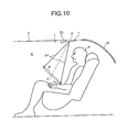
- the light-radiation direction Z-Z is inclined to an attachment surface of a ceiling trim T of an interior R of a vehicle (automobile) C as shown in Fig. 10. Further, the light-radiation direction Z-Z extends along a line connecting a predetermined point (which is a substantially central point) in a range E illuminated by spotlight L4 radiated from the spotlight source 6, and a substantially central point of the chip.
- the range E illuminated by the spotlight L4 radiated from the spotlight source 6 is, for example, an area at a hand of a person P who sits on a backseat when the vehicle interior lamp 1 is attached to the ceiling trim T above the backseat.
- character "G" indicates a rear window glass.
- the lamp housing 2 has a bottom plate 29 in a closed portion as an attachment surface, which is attached to the attachment surface of the ceiling trim T of the interior R of the vehicle (automobile) C.
- the spotlight source 6 which is arranged in the lamp chamber 16 and secured to the lamp housing 2 is inclined to the bottom plate 29 of the attachment surface of the lamp housing 2 as shown in Figs. 3 to 5.
- the light axis of the spotlight source 6 i.e., the light-radiation direction Z-Z of the spotlight source 6) is inclined to the bottom plate 29 of the attachment surface of the lamp housing 2.
- the fin-like heat sink member 19 of the spotlight source 6 is projected toward an opposite side of the lens 18 from another side of the main body substantially parallel to the light axis of the spotlight source 6 (i.e., the light-radiation direction Z-Z of the spotlight source 6). Therefore, the fin-like heat sink member 19 of the spotlight source 6 is inclined to the bottom plate 29 of the attachment surface of the lamp housing 2. Since the spotlight source 6 is inclined to the bottom plate 29 of the lamp housing 2, the fin-like heat sink member 19 is similarly inclined to the bottom plate 29 of the lamp housing 2. As shown in Figs.
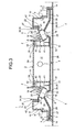
- the fin-like heat sink members 19, 19 of the right and the left spotlight sources 6, 6 are inclined inwardly toward each other to the side of a switch 23 when viewed from the back side of the vehicle interior lamp 1. Further, when viewed along a longitudinal section of the vehicle interior lamp 1 as shown in Figs. 3 and 4, the fin-like heat sink members 19, 19 of the right and the left spotlight sources 6, 6 are inclined inwardly toward each other. Further, when viewed in a section along a short-side direction of the vehicle interior lamp 1 as shown in Fig. 5, a longitudinal direction of the fin-like heat sink member 19 of the spotlight source 6 is inclined from inside the lamp chamber 16 to the lamp housing 2.
- the wide-light source 7 is a bulb-type light source and of a boat-like shape.
- the wide-light source 7 is secured to the lamp housing 2 with an electrode-cum-holder (not shown). As a result, the wide-light source 7 is arranged in the central wide-light lamp chamber 17.
- the spotlight sources 6, 6 are electrically connected to a side of a power source via switches 23, 23 by harnesses 33, 33.
- the wide-light source 7 is electrically connected to the side of the power source by a harness (not shown) via a door switch (not shown) which is turned on and off when a door of the vehicle is opened or closed or via a main switch (not shown) which is turned on and off by a driver.
- frustum-like depressions 24, 24, for example, circular-truncated-cone-like depressions are formed at positions corresponding to the spotlight sources 6, 6 arranged inside the right and the left spotlight lamp chambers 16, 16.
- a central axis of the depression 24 substantially coincides with the light-radiation direction Z-Z.
- radiation holes 25, 25 are formed to radiate the light from the spotlight sources 6, 6 onto the interior of the vehicle through the outer lens 4.
- a portion of the lens 18 serving as the light-radiating unit of the spotlight source 6 is projected outward from the radiation hole 25 (i.e., toward the side of the outer lens 4).
- the inner lens 3 as the lamp lens is made by two-color molding and has an outer side formed of a resin member 26 that has a light-guiding function, and an inner side formed of a lighttight resin member 27.
- the outer member 26 has an incident surface (not shown) for making the light from the spotlight source 6 come into the outer member 26 along the edge of the radiation hole 25.
- the outer member 26 further has a light-diffusing portion 30 for diffusing the light from the spotlight source 6 on a surface of the depression 24 of the inner lens 3.
- the light-diffusing portion 30 has numerous extremely small bumps formed through honing or grain finish, for example.
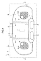
- the light-diffusing portion 30 is formed within a range where the surface (inclined inner surface) of the depression 24 extends, as shown by hatching in Fig. 1.
- a light-shielding rib 31 is integrally formed so as to oppose to the partition wall 15.
- the light-shielding rib 31 prevents the light from the spotlight sources 6, 6 arranged in the right and the left spotlight lamp chambers 16, 16 from leaking into the central wide-light lamp chamber 17.
- the light-shielding rib 31 prevents the light from the wide-light source 7 arranged in the central wide-light lamp chamber 17 from leaking into the right and the left spotlight lamp chambers 16, 16.
- the inner member 27 of the inner lens 3 has an opening 32 formed at a position corresponding to the central wide-light lamp chamber 17.
- the opening 32 of the inner member 27, which is a lighttight resin member, serves to pass the light from the wide-light source 7 arranged in the central wide-light lamp chamber 17 through the outer member 26 of the inner lens 3 and the outer lens 4 to illuminate the interior of the vehicle.
- the bottom plate 29 of the lamp housing 2 has backward-heat-discharging openings 34, 34 and lateral-heat-discharging openings 35, 35 formed at positions corresponding to the spotlight sources 6, 6.
- the backward-heat-discharging openings 34, 34 and the lateral-heat-discharging openings 35, 35 are communicated with a space extending in a direction along the inclination of the fin-like heat sink members 19, 19 of the right and the left spotlight sources 6, 6 (in other words, in a direction inclined inwardly to the side of the switch 23).
- the backward-heat-discharging opening 34 and the lateral-heat-discharging opening 35 may together form one big opening.
- the heat sink member 19 of the spotlight source 6 is arranged in the backward-heat-discharging opening 34 and the lateral-heat-discharging opening 35. Further, as shown in Fig. 5, the longitudinal direction of the fin of the heat sink member 19 is inclined from inside the lamp chamber 16 toward the backward-heat-discharging opening 34 and the lateral-heat-discharging opening 35.
- a step is formed down to the side of the lamp chamber 16.
- the step forms heat guiding paths 36, 36.
- the heat guiding paths 36, 36 are arranged in a predetermined direction from portions of the edges of the lateral-heat-discharging openings 35, 35, in other words, in an inward direction towards the side of the switch 23.
- a heat-guiding protrusion (rib) 37 is formed integrally.
- the heat guiding path 36 serves also as a wiring path that houses the harness 33 for wiring. Therefore, the heat guiding path 36 may be a depression, a groove, or a notch other than the step as far as the heat guiding path 36 can house the harness 33 for wiring.
- the heat guiding path 36 has a holder to hold the harness 33.
- the holder includes, for example, a notch 38, an elastic claw 39, and a fixing claw 40.
- the bracket 21 includes, as shown in Figs. 2 to 5, a fitting portion 41, a fixing portion 42, and a wall portion 43.
- the bracket 21 is a strong, elastic member with high heat conductivity, such as a thin steel plate.
- the fitting portion 41 is of a U-like shape and securely fits around the casing 20 of the main body of the spotlight source 6.
- the fitting portion 41 covers an area around the lens 18 on one surface and left and right side surfaces of the casing 20.
- an elastic fitting unit may be provided to each of the casing 20 and the fitting portion 41, so that the elastic fitting units elastically fit with each other so as to increase a fixing force of the spotlight source 6 and the bracket 21.
- a fitting hole (not shown) may be formed in the casing 20 while a fitting boss (not shown) may be formed on the fitting portion 41, and the fitting boss may be elastically fitted into the fitting hole.
- the fixing portion 42 is formed as a folded side part of the fitting portion and is integral to the fitting portion 41, or formed as an integral folded portion extending from the other side of the fitting portion 41 via the wall portion 43.
- the lens 18 of the light-radiating unit of the spotlight source 6 is arranged at the side of the inner lens 3 and the outer lens 4 of the lamp lens, whereas the heat sink member 19 of the spotlight source 6 is arranged at the side of the backward-heat-discharging opening 34 and the lateral-heat-discharging opening 35 of the lamp housing 2.
- the fixing portion 42 is secured by the screw 22 or the caulking 28 to the edges of the backward-heat-discharging opening 34 and the lateral-heat-discharging opening 35 of the lamp housing 2.
- the fixing portion 42 has a width substantially equal to the width of the fitting portion 41, or the wall portion 43.
- the wall portion 43 is arranged between the other side of the fitting portion 41 and the fixing portion 42.
- the wall portion 43 is arranged from the spotlight source 6 up to the edges of the backward-heat-discharging opening 34 and the lateral-heat-discharging opening 35.
- the wall portion 43 guides the heat generated from the spotlight source 6 to the backward-heat-discharging opening 34 and the lateral-heat-discharging opening 35. Further, the wall portion 43 prevents the heat generated from the spotlight source 6 from leaking outside a space enclosed by the wall portion 43, for example, to the side of the lens 18 of the spotlight source 6.
- a positioning boss 44 is integrally formed as a long boss serving as a positioning unit.
- a positioning hole 45 is formed as an elongated hole in the fitting portion 41 of the bracket 21.
- the vehicle interior lamp 1 of the embodiment has the above-described configuration. Functions thereof will be described below.
- the vehicle interior lamp 1 is attached to the ceiling trim T over the backseat in the interior R of the vehicle (automobile) C as shown in Fig. 10, for example, so that the side of the switch 23 is located at the opposite side from the rear window glass G.
- the spotlight source 6 lights up, and direct light L4 as spotlight passes through the lens 18, through the truncated-circular-cone-shaped depression 24 of the inner lens 3, and the outer lens 4, and illuminates the predetermined range E of the interior of the vehicle.
- a part of the light (not shown) from the lens 18 of the spotlight source 6 passes through the radiation hole 25 of the inner lens 3 and hits the light-diffusing portion 30 on the surface of the truncated-circular-cone-shaped depression 24 to be diffused. Further, a part of the light (not shown) from the lens 18 of the spotlight source 6 comes into the outer member 26 through the incident surface of the outer member 26 of the inner lens 3. The incident light coming into the outer member 26 through the incident surface is repeatedly reflected at an outer surface (surface) of the outer member 26 and a boundary between the outer member 26 and the inner member 27 due to a light-guiding function of the outer member 26, and guided in the outer member 26. At the same time, a part of the light (not shown) is emitted to the outside from the outer surface of the outer member 26.
- the wide-light source 7 lights up, and the wide light from the wide-light source 7 passes through the outer member 26 of the inner lens 2 and the outer lens 4, so as to widely illuminate a predetermined range in the interior of the vehicle.
- the spotlight source 6 When the spotlight source 6 is turned on, the heat is generated in the casing 20 of the main body of the spotlight source 6. The heat is transferred to the heat sink member 19 from the casing 20 of the main body of the spotlight source 6. The heat transferred to the heat sink member 19 is discharged outside the lamp chamber 16 from inside the lamp chamber 16 through the backward-heat-discharging opening 34 and the lateral-heat-discharging opening 35 along the longitudinal direction of the fin of the heat sink member 19 as shown by a solid arrow shown in Figs. 3, 5, and 6.
- the heat generated in the casing 20 of the main body of the spotlight source 6 is prevented from leaking out from a space enclosed by the wall portion 43, e.g., to the side of the lens 18 of the spotlight source 6, by the wall portion 43 of the bracket 21.
- the heat generated in the casing 20 of the main body of the spotlight source 6 is guided from inside the lamp chamber 16 to the backward-heat-discharging opening 34 and the lateral-heat-discharging opening 35 by the wall portion 43 of the bracket 21.
- the heat guided from inside the lamp chamber 16 to the backward-heat-discharging opening 34 and the lateral-heat-discharging opening 35 passes through the backward-heat-discharging opening 34 and the lateral-heat-discharging opening 35, and is discharged outside the lamp chamber 16.
- the heat discharged outside the lamp chamber 16 is guided from the lateral-heat-discharging opening 35 along the heat guiding path 36 to the side of the switch 23 at the opposite side from the rear window glass G. Further, the heat discharged from the heat sink member 19 is guided by the heat-guiding protrusion 37 on the edges of the backward-heat-discharging opening 34, the lateral-heat-discharging opening 35, and the heat guiding path 36 to the side of the switch 23 opposite to the rear window glass G.
- the vehicle interior lamp 1 of the embodiment has the configuration and functions as described above. Effects thereof will be described below.
- the heat generated in the main body of the spotlight source 6 is efficiently discharged through the heat sink member 19 inside the lamp chamber 16, and the backward-heat-discharging opening 34 and the lateral-heat-discharging opening 35 of the lamp housing 2 to the outside of the lamp chamber 16.
- the heat generated in the casing 20 of the main body of the spotlight source 6 is transferred from inside the lamp chamber 16 to the side of the backward-heat-discharging opening 34 and the lateral-heat-discharging opening 35 of the lamp housing 2 along the longitudinal direction of the fin of the heat sink member 19 in the heat sink member 19, as shown by a solid arrow in Fig.
- the vehicle interior lamp 1 of the embodiment takes full measures against heat of the semiconductor-type light source which is the spotlight source 6, whereby a high-output semiconductor-type light source can be used.
- the light axis of the spotlight source 6 arranged inside the lamp chamber 16 is substantially parallel to the longitudinal direction of the fin of the heat sink member 19.
- the light-radiation direction Z-Z of the spotlight source 6 is inclined to the attachment surface of the ceiling trim T of the interior R of the vehicle (automobile) C, i.e., the bottom plate 29 of the attachment surface of the lamp housing 2. Therefore, in the vehicle interior lamp 1 of the embodiment, when the light axis of the spotlight source 6 is aligned with the light-radiation direction Z-Z of the spotlight source 6, the light axis of the spotlight source 6 is inclined to the bottom plate 29 of the attachment surface of the lamp housing 2.
- the vehicle interior lamp 1 of the embodiment can readily and securely incline the longitudinal direction of the fin of the heat sink member 19 from the inside of the lamp chamber 16 to the backward-heat-discharging opening 34 and the lateral-heat-discharging opening 35. Therefore, the vehicle interior lamp 1 of the embodiment can efficiently discharge the heat generated in the casing 20 of the main body of the spotlight source 6 from inside the lamp chamber 16 along the longitudinal direction of the fin of the heat sink member 19 which is inclined toward the backward-heat-discharging opening 34 and the lateral-heat-discharging opening 35, from inside the lamp chamber 16 through the backward-heat-discharging opening 34 and the lateral-heat-discharging opening 35 to the outside of the lamp chamber 16.
- the vehicle interior lamp 1 of the embodiment can provide the spotlight with high light directionality readily and securely since the spotlight source 6 is configured with a semiconductor-type light source such as an LED having light directionality. Further, since the vehicle interior lamp 1 of the embodiment can provide the spotlight with high light directionality, glare can be prevented from annoying people other than a user of the spotlight.
- the heat generated in the casing 20 of the main body of the spotlight source 6 is guided in a predetermined direction via the heat sink member 19 and through the backward-heat-discharging opening 34 and the lateral-heat-discharging opening 35 of the lamp housing 2 following the heat-guiding path 36, and thereby efficiently discharged outside the lamp chamber 16.
- the vehicle interior lamp 1 of the embodiment takes full measures against the heat of the semiconductor-type light source which is the spotlight source 6, whereby a high-output semiconductor-type light source can be used.
- the vehicle interior lamp 1 of the embodiment can guide the heat of the spotlight source 6 by the heat guiding path 36 in a predetermined direction, e.g., direction to the side of the switch 23 at the opposite side of the rear window glass G in the embodiment.
- the vehicle interior lamp 1 of the embodiment can minimize the inconvenience caused by the discharge of the heat from the spotlight source 6.
- the vehicle interior lamp 1 of the embodiment can prevent the fogging of the rear window glass G by guiding the heat of the spotlight source 6 to the opposite side from the rear window glass G.
- the vehicle interior lamp 1 of the embodiment has the heat-guiding protrusion 37 along the edges of the backward-heat-discharging opening 34, the lateral-heat-discharging opening 35, and the heat-guiding path 36, the vehicle interior lamp 1 of the embodiment can guide the heat of the spotlight source 6 in a predetermined direction even more securely. Still further, since the vehicle interior lamp 1 of the embodiment has the heat-guiding protrusion 37 along the edges of the backward-heat-discharging opening 34, the lateral-heat-discharging opening 35, and the heat-guiding path 36, the strength of the lamp housing 2 can be increased.
- the heat-guiding path 36 is also used as the wiring path through which the harness 33 is arranged and electrically connected to the spotlight source 6.
- the vehicle interior lamp 1 of the embodiment has a fixing unit such as the notch 38, the elastic claw 39, and the fixing claw 40 in the heat-guiding path 36 to secure the harness 33. Therefore, the vehicle interior lamp 1 of the embodiment can arrange the harness 33 of the spotlight source 6 readily and securely in a shortest possible distance. Still further, the vehicle interior lamp 1 of the embodiment simplifies a wiring work of the harness 33 of the spotlight source 6, and shortens the harness 33, whereby manufacturing cost can be decreased.
- the harness 33 can be arranged in a shortest possible distance.
- the fixing unit of the harness 33 such as the notch 38, the elastic claw 39, and the fixing claw 40 can be provided outside the lamp housing 2 in the heat-guiding path 36, which is a wiring path of the step.
- the wall portion 43 of the bracket 21 can prevent the heat generated from the spotlight source 6 from leaking outside the space surrounded by the wall portion 43, e.g., to the side of the lens 18 of the spotlight source 6.
- the vehicle interior lamp 1 of the embodiment efficiently discharges the heat generated from the spotlight source 6 by guiding the heat from the spotlight source 6 along the wall portion 43 of the bracket 21 to the backward-heat-discharging opening 34 and the lateral-heat-discharging opening 35 of the lamp housing 2, and through the backward-heat-discharging opening 34 and the lateral-heat-discharging opening 35 to the outside of the lamp chamber 16.
- the vehicle interior lamp 1 of the embodiment takes full measures against heat of the semiconductor-type light source, which is the spotlight source 6, whereby a high-output semiconductor-type light source can be used.
- the spotlight source 6 is secured to the lamp housing 2 by the bracket 21, whereby the spotlight source 6 can be secured to the lamp housing 2 with a high degree of accuracy. Specifically, even when the light axis of the spotlight source 6 is aligned with the light-radiation direction Z-Z of the spotlight source 6, and the spotlight source 6 is secured to the bottom plate 29 of the attachment surface of the lamp housing 2 in an inclined state, the spotlight source 6 can be secured to the lamp housing 2 in an inclined state with a high degree of accuracy.
- the width of the fixing portion 42 of the bracket 21 is substantially equal to the width of the fitting portion 41 or the wall portion 43 of the bracket 21, and therefore, a sufficient area can be secured for fixing the fixing portion 42 of the bracket 21 to the lamp housing 2.
- the spotlight source 6 can be secured to the lamp housing 2 with a still higher degree of accuracy.
- the bracket 21 is configured with a strong, elastic member having a high heat conductivity, whereby the effect of discharging the heat from the spotlight source 6 can be further enhanced, and the spotlight source 6 can be securely fixed to the lamp housing 2 via the bracket 21.
- the vehicle interior lamp 1 is explained as being attached to the ceiling trim T over the backseat near the rear window glass G.
- the present invention can be applied to a vehicle interior lamp attached to a position other than the ceiling trim T over the backseat near the rear window glass G, e.g., a ceiling trim over a front seat near a front window glass.
- the positioning unit includes the positioning protrusion 44 which is an elongated boss and the positioning hole 45 which is an elongated hole.
- the positioning unit may be configured with an element other than the positioning protrusion 44 as the elongated boss and the positioning hole 45 as the elongated hole.
- the positioning unit may be configured with one or more small circular protrusion(s) and one or more small circular hole(s).
Abstract
Description
- The present document incorporates by reference the entire contents of
Japanese priority document, 2006-228367 - The present invention relates to a vehicle interior lamp that uses a semiconductor-type light source having light directionality as a light source. In particular, the present invention relates to a vehicle interior lamp that can efficiently discharge (release) heat generated from a light source.
- The above type of vehicle interior lamps has been conventionally known as exemplified by, for example, a vehicle interior lamp described in
Japanese Patent Application Laid-Open No. 2002-331868 - The conventional vehicle interior lamps, however, do not take measures against heat generated from the LED. Therefore, there is a problem in the use of semiconductor-type light sources such as high-output LEDs in the conventional vehicle interior lamps.
- It is an object of the present invention to at least partially solve the problems in the conventional technology.
- A vehicle interior lamp according to one aspect of the present invention includes a light source that is a semiconductor-type light source having light directionality, the light source having a unit structure including a main body, a light-radiating unit that is provided in the main body to radiate light, and a heat sink member that is provided in the main body, a lamp housing having a heat-discharge opening arranged at a position corresponding to the light source, a lamp lens, and a lamp chamber delimited by the lamp housing and the lamp lens.
- The above and other objects, features, advantages and technical and industrial significance of this invention will be better understood by reading the following detailed description of presently preferred embodiments of the invention, when considered in connection with the accompanying drawings.
-
- Fig. 1 is a front view of a vehicle interior lamp according to an embodiment of the present invention;
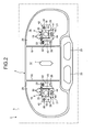
- Fig. 2 is a front view of an interior of a spotlight lamp chamber and an interior of a wide-light lamp chamber with an inner lens and an outer lens removed from the vehicle interior lamp according to the embodiment;
- Fig. 3 is a sectional view along line III-III of FIG. 1;
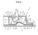
- Fig. 4 is a sectional view along line IV-IV of FIG. 1;
- Fig. 5 is a sectional view along line V-V of FIG. 1;
- Fig. 6 is a perspective view of the vehicle interior lamp according to the embodiment viewed from a back side;
- Fig. 7 is an enlarged partial perspective view of the vehicle interior lamp according to the embodiment viewed from the back side;
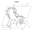
- Fig. 8 is an enlarged partial perspective view of the vehicle interior lamp according to the embodiment viewed from the back side with a spotlight source and a harness removed;
- Fig. 9 is a back view of the vehicle interior lamp according to the embodiment; and
- Fig. 10 is a view for explaining a use situation of the vehicle interior lamp according to the embodiment.
- Exemplary embodiments of a vehicle interior lamp according to the present invention will be described in detail below with reference to the accompanying drawings. The present invention is not limited to the embodiments. When the vehicle interior lamp according to the embodiment of the present invention is installed in a vehicle (see Fig. 10), a front side shown in Figs. 1 and 2 becomes a bottom side (i.e., lower side). Further, when the vehicle interior lamp according to the embodiment of the present invention is installed in a vehicle (see Fig. 10), a back side shown in Figs. 6 to 9 becomes a planar side (i.e., upper side).
- A configuration of the vehicle interior lamp according to the embodiment will be described below. A vehicle
interior lamp 1 according to the embodiment includes alamp housing 2, aninner lens 3 and anouter lens 4 as lamp lenses, alamp cover 5, aspotlight source 6 having a semiconductor-type light source having light directionality, a wide-light source 7, and abracket 21. - The
lamp housing 2 of the embodiment is a lighttight member. Thelamp housing 2 is of a U-shape in section with one side (i.e. front side) open and another side (i.e. back side) closed. Thelamp housing 2 has anopening 8, and astep 9 is integrally formed along an edge of the opening 8. Thelamp cover 5 of the embodiment is a lighttight member. Thelamp cover 5 has a cover-like shape. At a central portion of thelamp cover 5, an opening 10 of approximately the same size as that of the opening 8 of thelamp housing 2 is provided. Further, aninner step 11 is integrally formed along an edge of the opening 10 of thelamp cover 5. Thestep 9 of the lamp housing 2 fits around theinner step 11 of thelamp cover 5. In a fitted state, thelamp housing 2 is secured to thelamp cover 5 with a fixing unit (not shown) such as a screw or an elastic engagement member. - The
outer lens 4 of the embodiment is an optically-transparent resin member. Theouter lens 4 is of a shallow U-shape in section with one side (i.e., back side) open and another side (i.e., front side) closed. Theouter lens 4 has anopening 12, and awall 13 is integrally formed along an edge of the opening 12. Theinner lens 3 is of a platelike shape. Theinner lens 3 is fitted inside thewall 13 of the opening 12 of theouter lens 4. In a fitted state, theinner lens 3 is secured to theouter lens 4 with a fixing unit (not shown) such as an elastic engagement member. - On an outer circumference of the
lamp cover 5 outside theinner step 11, anouter step 14 is formed integrally. Thewall 13 of theouter lens 4 to which theinner lens 3 is secured fits into theouter step 14 of thelamp cover 5 to which thelamp housing 2 is secured. In a fitted state, theouter lens 4 is secured to thelamp cover 5 with a fixing unit (not shown) such as an elastic engagement member. - A lamp chamber is delimited by the
lamp housing 2, theinner lens 3, theouter lens 4, and thelamp cover 5. An interior of the lamp chamber is further divided into right and leftspotlight lamp chambers light lamp chamber 17 by twopartition walls 15 at right and left ends of thelamp housing 2. - In the right and the left
spotlight lamp chambers spotlight sources light lamp chamber 17, the wide-light source 7 is arranged. - The
spotlight source 6 is a semiconductor-type light source such as an LED having light directionality. Thespotlight source 6 has a unit structure including a main body, a light-radiating unit which is provided on one surface of the main body to radiate light, and a fin-likeheat sink member 19 which is provided on another surface of the main body and has a fin-like shape. More specifically, thespotlight source 6 includes a chip (not shown) of a semiconductor-type light source, a substrate (not shown) on which the chip is mounted, alens 18 which covers the chip and the substrate, the fin-likeheat sink member 19 which is directly or indirectly attached to the substrate via a heat-conductive member (not shown) and has plural fins (four fins in the embodiment), and aresin casing 20 which holds the chip, the substrate, thelens 18, and theheat sink member 19. The chip, the substrate, and thecasing 20 constitute the main body of thespotlight source 6, whereas thelens 18 constitutes the light-radiating unit of thespotlight source 6. - Each of the
spotlight sources lamp housing 2 via thebracket 21 with ascrew 22 or a caulking 28. As a result, thespotlight sources spotlight lamp chambers lens 18 of thespotlight source 6 is arranged at the side of theinner lens 3 and theouter lens 4. On the other hand, theheat sink member 19 of thespotlight source 6 is arranged at the side of thelamp housing 2. Thebracket 21 has functions of securing thespotlight source 6, and of guiding and discharging heat generated by thespotlight source 6 in a predetermined direction. - A light axis (i.e., axis on which light directionality is 0°) of the
spotlight source 6 which is configured with the semiconductor-type light source such as an LED having light directionality is aligned with a light-radiation direction Z-Z of thespotlight source 6. The light-radiation direction Z-Z is inclined to an attachment surface of a ceiling trim T of an interior R of a vehicle (automobile) C as shown in Fig. 10. Further, the light-radiation direction Z-Z extends along a line connecting a predetermined point (which is a substantially central point) in a range E illuminated by spotlight L4 radiated from thespotlight source 6, and a substantially central point of the chip. The range E illuminated by the spotlight L4 radiated from thespotlight source 6 is, for example, an area at a hand of a person P who sits on a backseat when the vehicleinterior lamp 1 is attached to the ceiling trim T above the backseat. In Fig. 10, character "G" indicates a rear window glass. - The
lamp housing 2 has abottom plate 29 in a closed portion as an attachment surface, which is attached to the attachment surface of the ceiling trim T of the interior R of the vehicle (automobile) C. As a result, thespotlight source 6 which is arranged in thelamp chamber 16 and secured to thelamp housing 2 is inclined to thebottom plate 29 of the attachment surface of thelamp housing 2 as shown in Figs. 3 to 5. In other words, the light axis of the spotlight source 6 (i.e., the light-radiation direction Z-Z of the spotlight source 6) is inclined to thebottom plate 29 of the attachment surface of thelamp housing 2. - The fin-like
heat sink member 19 of thespotlight source 6 is projected toward an opposite side of thelens 18 from another side of the main body substantially parallel to the light axis of the spotlight source 6 (i.e., the light-radiation direction Z-Z of the spotlight source 6). Therefore, the fin-likeheat sink member 19 of thespotlight source 6 is inclined to thebottom plate 29 of the attachment surface of thelamp housing 2. Since thespotlight source 6 is inclined to thebottom plate 29 of thelamp housing 2, the fin-likeheat sink member 19 is similarly inclined to thebottom plate 29 of thelamp housing 2. As shown in Figs. 6, 7, and 9, for example, the fin-likeheat sink members left spotlight sources switch 23 when viewed from the back side of the vehicleinterior lamp 1. Further, when viewed along a longitudinal section of the vehicleinterior lamp 1 as shown in Figs. 3 and 4, the fin-likeheat sink members left spotlight sources interior lamp 1 as shown in Fig. 5, a longitudinal direction of the fin-likeheat sink member 19 of thespotlight source 6 is inclined from inside thelamp chamber 16 to thelamp housing 2. - The wide-
light source 7 is a bulb-type light source and of a boat-like shape. The wide-light source 7 is secured to thelamp housing 2 with an electrode-cum-holder (not shown). As a result, the wide-light source 7 is arranged in the central wide-light lamp chamber 17. - The
spotlight sources harnesses light source 7 is electrically connected to the side of the power source by a harness (not shown) via a door switch (not shown) which is turned on and off when a door of the vehicle is opened or closed or via a main switch (not shown) which is turned on and off by a driver. - In the
inner lens 3 serving as the lamp lens, frustum-like depressions 24, 24, for example, circular-truncated-cone-like depressions are formed at positions corresponding to thespotlight sources spotlight lamp chambers spotlight sources outer lens 4. A portion of thelens 18 serving as the light-radiating unit of thespotlight source 6 is projected outward from the radiation hole 25 (i.e., toward the side of the outer lens 4). - The
inner lens 3 as the lamp lens is made by two-color molding and has an outer side formed of aresin member 26 that has a light-guiding function, and an inner side formed of alighttight resin member 27. Theouter member 26 has an incident surface (not shown) for making the light from thespotlight source 6 come into theouter member 26 along the edge of theradiation hole 25. Theouter member 26 further has a light-diffusing portion 30 for diffusing the light from thespotlight source 6 on a surface of the depression 24 of theinner lens 3. The light-diffusing portion 30 has numerous extremely small bumps formed through honing or grain finish, for example. The light-diffusing portion 30 is formed within a range where the surface (inclined inner surface) of the depression 24 extends, as shown by hatching in Fig. 1. - On the
inner member 27 of theinner lens 3, a light-shieldingrib 31 is integrally formed so as to oppose to thepartition wall 15. The light-shieldingrib 31 prevents the light from thespotlight sources spotlight lamp chambers light lamp chamber 17. At the same time, the light-shieldingrib 31 prevents the light from the wide-light source 7 arranged in the central wide-light lamp chamber 17 from leaking into the right and the leftspotlight lamp chambers - The
inner member 27 of theinner lens 3 has anopening 32 formed at a position corresponding to the central wide-light lamp chamber 17. Theopening 32 of theinner member 27, which is a lighttight resin member, serves to pass the light from the wide-light source 7 arranged in the central wide-light lamp chamber 17 through theouter member 26 of theinner lens 3 and theouter lens 4 to illuminate the interior of the vehicle. - As shown in Figs. 3 to 9, the
bottom plate 29 of thelamp housing 2 has backward-heat-dischargingopenings openings spotlight sources openings openings heat sink members left spotlight sources 6, 6 (in other words, in a direction inclined inwardly to the side of the switch 23). The backward-heat-dischargingopening 34 and the lateral-heat-dischargingopening 35 may together form one big opening. - The
heat sink member 19 of thespotlight source 6 is arranged in the backward-heat-dischargingopening 34 and the lateral-heat-dischargingopening 35. Further, as shown in Fig. 5, the longitudinal direction of the fin of theheat sink member 19 is inclined from inside thelamp chamber 16 toward the backward-heat-dischargingopening 34 and the lateral-heat-dischargingopening 35. - As shown in Figs. 6 to 9, at portions along the edges of the lateral-heat-discharging
openings lamp housing 2, a step is formed down to the side of thelamp chamber 16. The step formsheat guiding paths heat guiding paths openings switch 23. On the edges of the backward-heat-dischargingopening 34, the lateral-heat-dischargingopening 35, and theheat guiding path 36, a heat-guiding protrusion (rib) 37 is formed integrally. - The
heat guiding path 36 serves also as a wiring path that houses theharness 33 for wiring. Therefore, theheat guiding path 36 may be a depression, a groove, or a notch other than the step as far as theheat guiding path 36 can house theharness 33 for wiring. Theheat guiding path 36 has a holder to hold theharness 33. The holder includes, for example, anotch 38, anelastic claw 39, and a fixingclaw 40. - The
bracket 21 includes, as shown in Figs. 2 to 5, afitting portion 41, a fixingportion 42, and awall portion 43. Thebracket 21 is a strong, elastic member with high heat conductivity, such as a thin steel plate. - The
fitting portion 41 is of a U-like shape and securely fits around thecasing 20 of the main body of thespotlight source 6. Thefitting portion 41 covers an area around thelens 18 on one surface and left and right side surfaces of thecasing 20. Alternatively, an elastic fitting unit may be provided to each of thecasing 20 and thefitting portion 41, so that the elastic fitting units elastically fit with each other so as to increase a fixing force of thespotlight source 6 and thebracket 21. For example, a fitting hole (not shown) may be formed in thecasing 20 while a fitting boss (not shown) may be formed on thefitting portion 41, and the fitting boss may be elastically fitted into the fitting hole. - The fixing
portion 42 is formed as a folded side part of the fitting portion and is integral to thefitting portion 41, or formed as an integral folded portion extending from the other side of thefitting portion 41 via thewall portion 43. Thelens 18 of the light-radiating unit of thespotlight source 6 is arranged at the side of theinner lens 3 and theouter lens 4 of the lamp lens, whereas theheat sink member 19 of thespotlight source 6 is arranged at the side of the backward-heat-dischargingopening 34 and the lateral-heat-dischargingopening 35 of thelamp housing 2. In this state, the fixingportion 42 is secured by thescrew 22 or thecaulking 28 to the edges of the backward-heat-dischargingopening 34 and the lateral-heat-dischargingopening 35 of thelamp housing 2. As a result, thespotlight source 6 is secured to thelamp housing 2. The fixingportion 42 has a width substantially equal to the width of thefitting portion 41, or thewall portion 43. - The
wall portion 43 is arranged between the other side of thefitting portion 41 and the fixingportion 42. In other words, thewall portion 43 is arranged from thespotlight source 6 up to the edges of the backward-heat-dischargingopening 34 and the lateral-heat-dischargingopening 35. Thewall portion 43 guides the heat generated from thespotlight source 6 to the backward-heat-dischargingopening 34 and the lateral-heat-dischargingopening 35. Further, thewall portion 43 prevents the heat generated from thespotlight source 6 from leaking outside a space enclosed by thewall portion 43, for example, to the side of thelens 18 of thespotlight source 6. - On one surface of the
casing 20 of the main body of thespotlight source 6, apositioning boss 44 is integrally formed as a long boss serving as a positioning unit. On the other hand, apositioning hole 45 is formed as an elongated hole in thefitting portion 41 of thebracket 21. When thepositioning boss 44 is fitted to thepositioning hole 45, positions of thecasing 20 and thefitting portion 41 are determined. In this state, thecasing 20 and thefitting portion 41 are fitted with each other. - The vehicle
interior lamp 1 of the embodiment has the above-described configuration. Functions thereof will be described below. - The vehicle
interior lamp 1 according to the embodiment is attached to the ceiling trim T over the backseat in the interior R of the vehicle (automobile) C as shown in Fig. 10, for example, so that the side of theswitch 23 is located at the opposite side from the rear window glass G. When theswitch 23 is turned on, thespotlight source 6 lights up, and direct light L4 as spotlight passes through thelens 18, through the truncated-circular-cone-shaped depression 24 of theinner lens 3, and theouter lens 4, and illuminates the predetermined range E of the interior of the vehicle. - A part of the light (not shown) from the
lens 18 of thespotlight source 6 passes through theradiation hole 25 of theinner lens 3 and hits the light-diffusing portion 30 on the surface of the truncated-circular-cone-shaped depression 24 to be diffused. Further, a part of the light (not shown) from thelens 18 of thespotlight source 6 comes into theouter member 26 through the incident surface of theouter member 26 of theinner lens 3. The incident light coming into theouter member 26 through the incident surface is repeatedly reflected at an outer surface (surface) of theouter member 26 and a boundary between theouter member 26 and theinner member 27 due to a light-guiding function of theouter member 26, and guided in theouter member 26. At the same time, a part of the light (not shown) is emitted to the outside from the outer surface of theouter member 26. - When the door switch or the main switch is turned on, the wide-
light source 7 lights up, and the wide light from the wide-light source 7 passes through theouter member 26 of theinner lens 2 and theouter lens 4, so as to widely illuminate a predetermined range in the interior of the vehicle. - When the
spotlight source 6 is turned on, the heat is generated in thecasing 20 of the main body of thespotlight source 6. The heat is transferred to theheat sink member 19 from thecasing 20 of the main body of thespotlight source 6. The heat transferred to theheat sink member 19 is discharged outside thelamp chamber 16 from inside thelamp chamber 16 through the backward-heat-dischargingopening 34 and the lateral-heat-dischargingopening 35 along the longitudinal direction of the fin of theheat sink member 19 as shown by a solid arrow shown in Figs. 3, 5, and 6. - Further, the heat generated in the
casing 20 of the main body of thespotlight source 6 is prevented from leaking out from a space enclosed by thewall portion 43, e.g., to the side of thelens 18 of thespotlight source 6, by thewall portion 43 of thebracket 21. In addition, the heat generated in thecasing 20 of the main body of thespotlight source 6 is guided from inside thelamp chamber 16 to the backward-heat-dischargingopening 34 and the lateral-heat-dischargingopening 35 by thewall portion 43 of thebracket 21. The heat guided from inside thelamp chamber 16 to the backward-heat-dischargingopening 34 and the lateral-heat-dischargingopening 35 passes through the backward-heat-dischargingopening 34 and the lateral-heat-dischargingopening 35, and is discharged outside thelamp chamber 16. - The heat discharged outside the
lamp chamber 16 is guided from the lateral-heat-dischargingopening 35 along theheat guiding path 36 to the side of theswitch 23 at the opposite side from the rear window glass G. Further, the heat discharged from theheat sink member 19 is guided by the heat-guidingprotrusion 37 on the edges of the backward-heat-dischargingopening 34, the lateral-heat-dischargingopening 35, and theheat guiding path 36 to the side of theswitch 23 opposite to the rear window glass G. - The vehicle
interior lamp 1 of the embodiment has the configuration and functions as described above. Effects thereof will be described below. - In the vehicle
interior lamp 1 of the embodiment, the heat generated in the main body of thespotlight source 6 is efficiently discharged through theheat sink member 19 inside thelamp chamber 16, and the backward-heat-dischargingopening 34 and the lateral-heat-dischargingopening 35 of thelamp housing 2 to the outside of thelamp chamber 16. In other words, the heat generated in thecasing 20 of the main body of thespotlight source 6 is transferred from inside thelamp chamber 16 to the side of the backward-heat-dischargingopening 34 and the lateral-heat-dischargingopening 35 of thelamp housing 2 along the longitudinal direction of the fin of theheat sink member 19 in theheat sink member 19, as shown by a solid arrow in Fig. 5, and efficiently discharged through the backward-heat-dischargingopening 34 and the lateral-heat-dischargingopening 35 to the outside of thelamp chamber 16. Thus, the vehicleinterior lamp 1 of the embodiment takes full measures against heat of the semiconductor-type light source which is thespotlight source 6, whereby a high-output semiconductor-type light source can be used. - Further, in the vehicle
interior lamp 1 of the embodiment, the light axis of thespotlight source 6 arranged inside thelamp chamber 16 is substantially parallel to the longitudinal direction of the fin of theheat sink member 19. On the other hand, in the vehicleinterior lamp 1 of the embodiment, the light-radiation direction Z-Z of thespotlight source 6 is inclined to the attachment surface of the ceiling trim T of the interior R of the vehicle (automobile) C, i.e., thebottom plate 29 of the attachment surface of thelamp housing 2. Therefore, in the vehicleinterior lamp 1 of the embodiment, when the light axis of thespotlight source 6 is aligned with the light-radiation direction Z-Z of thespotlight source 6, the light axis of thespotlight source 6 is inclined to thebottom plate 29 of the attachment surface of thelamp housing 2. As a result, the vehicleinterior lamp 1 of the embodiment can readily and securely incline the longitudinal direction of the fin of theheat sink member 19 from the inside of thelamp chamber 16 to the backward-heat-dischargingopening 34 and the lateral-heat-dischargingopening 35. Therefore, the vehicleinterior lamp 1 of the embodiment can efficiently discharge the heat generated in thecasing 20 of the main body of thespotlight source 6 from inside thelamp chamber 16 along the longitudinal direction of the fin of theheat sink member 19 which is inclined toward the backward-heat-dischargingopening 34 and the lateral-heat-dischargingopening 35, from inside thelamp chamber 16 through the backward-heat-dischargingopening 34 and the lateral-heat-dischargingopening 35 to the outside of thelamp chamber 16. - In addition, the vehicle
interior lamp 1 of the embodiment can provide the spotlight with high light directionality readily and securely since thespotlight source 6 is configured with a semiconductor-type light source such as an LED having light directionality. Further, since the vehicleinterior lamp 1 of the embodiment can provide the spotlight with high light directionality, glare can be prevented from annoying people other than a user of the spotlight. - Further, as shown by a solid arrow in Fig. 6, in the vehicle
interior lamp 1 of the embodiment, the heat generated in thecasing 20 of the main body of thespotlight source 6 is guided in a predetermined direction via theheat sink member 19 and through the backward-heat-dischargingopening 34 and the lateral-heat-dischargingopening 35 of thelamp housing 2 following the heat-guidingpath 36, and thereby efficiently discharged outside thelamp chamber 16. Thus, the vehicleinterior lamp 1 of the embodiment takes full measures against the heat of the semiconductor-type light source which is thespotlight source 6, whereby a high-output semiconductor-type light source can be used. In particular, the vehicleinterior lamp 1 of the embodiment can guide the heat of thespotlight source 6 by theheat guiding path 36 in a predetermined direction, e.g., direction to the side of theswitch 23 at the opposite side of the rear window glass G in the embodiment. Thus, the vehicleinterior lamp 1 of the embodiment can minimize the inconvenience caused by the discharge of the heat from thespotlight source 6. In particular, the vehicleinterior lamp 1 of the embodiment can prevent the fogging of the rear window glass G by guiding the heat of thespotlight source 6 to the opposite side from the rear window glass G. - Further, since the vehicle
interior lamp 1 of the embodiment has the heat-guidingprotrusion 37 along the edges of the backward-heat-dischargingopening 34, the lateral-heat-dischargingopening 35, and the heat-guidingpath 36, the vehicleinterior lamp 1 of the embodiment can guide the heat of thespotlight source 6 in a predetermined direction even more securely. Still further, since the vehicleinterior lamp 1 of the embodiment has the heat-guidingprotrusion 37 along the edges of the backward-heat-dischargingopening 34, the lateral-heat-dischargingopening 35, and the heat-guidingpath 36, the strength of thelamp housing 2 can be increased. - Still further, in the vehicle
interior lamp 1 of the embodiment, the heat-guidingpath 36 is also used as the wiring path through which theharness 33 is arranged and electrically connected to thespotlight source 6. Further, the vehicleinterior lamp 1 of the embodiment has a fixing unit such as thenotch 38, theelastic claw 39, and the fixingclaw 40 in the heat-guidingpath 36 to secure theharness 33. Therefore, the vehicleinterior lamp 1 of the embodiment can arrange theharness 33 of thespotlight source 6 readily and securely in a shortest possible distance. Still further, the vehicleinterior lamp 1 of the embodiment simplifies a wiring work of theharness 33 of thespotlight source 6, and shortens theharness 33, whereby manufacturing cost can be decreased. Specifically, when the step provided one level downward is arranged in a power supply unit (i.e., a connector of the harness) of thespotlight source 6, theharness 33 can be arranged in a shortest possible distance. Still further, when the step is provided one level downward in thelamp housing 2, the fixing unit of theharness 33 such as thenotch 38, theelastic claw 39, and the fixingclaw 40 can be provided outside thelamp housing 2 in the heat-guidingpath 36, which is a wiring path of the step. - Still further, in the vehicle
interior lamp 1 of the embodiment, thewall portion 43 of thebracket 21 can prevent the heat generated from thespotlight source 6 from leaking outside the space surrounded by thewall portion 43, e.g., to the side of thelens 18 of thespotlight source 6. In addition, as shown by the solid arrow of Fig. 3, the vehicleinterior lamp 1 of the embodiment efficiently discharges the heat generated from thespotlight source 6 by guiding the heat from thespotlight source 6 along thewall portion 43 of thebracket 21 to the backward-heat-dischargingopening 34 and the lateral-heat-dischargingopening 35 of thelamp housing 2, and through the backward-heat-dischargingopening 34 and the lateral-heat-dischargingopening 35 to the outside of thelamp chamber 16. Thus, the vehicleinterior lamp 1 of the embodiment takes full measures against heat of the semiconductor-type light source, which is thespotlight source 6, whereby a high-output semiconductor-type light source can be used. - Still further, in the vehicle
interior lamp 1 of the embodiment, thespotlight source 6 is secured to thelamp housing 2 by thebracket 21, whereby thespotlight source 6 can be secured to thelamp housing 2 with a high degree of accuracy. Specifically, even when the light axis of thespotlight source 6 is aligned with the light-radiation direction Z-Z of thespotlight source 6, and thespotlight source 6 is secured to thebottom plate 29 of the attachment surface of thelamp housing 2 in an inclined state, thespotlight source 6 can be secured to thelamp housing 2 in an inclined state with a high degree of accuracy. - Still further, in the vehicle
interior lamp 1 of the embodiment, the width of the fixingportion 42 of thebracket 21 is substantially equal to the width of thefitting portion 41 or thewall portion 43 of thebracket 21, and therefore, a sufficient area can be secured for fixing the fixingportion 42 of thebracket 21 to thelamp housing 2. Thus, in the vehicleinterior lamp 1 of the embodiment, even when the light axis of thespotlight source 6 is inclined relative to three directions (e.g., X-direction, Y-direction, and Z-direction; for example, X-direction and Y-direction are orthogonal with each other on thebottom plate 29 of the attachment surface of thelamp housing 2, and Z-direction is orthogonal to thebottom plate 29 of the attachment surface of the lamp housing 2), thespotlight source 6 can be secured to thelamp housing 2 with a still higher degree of accuracy. - Still further, in the vehicle
interior lamp 1 of the embodiment, thebracket 21 is configured with a strong, elastic member having a high heat conductivity, whereby the effect of discharging the heat from thespotlight source 6 can be further enhanced, and thespotlight source 6 can be securely fixed to thelamp housing 2 via thebracket 21. - Examples other than the above described embodiment will be described below. In the above embodiment, the vehicle
interior lamp 1 is explained as being attached to the ceiling trim T over the backseat near the rear window glass G. The present invention, however, can be applied to a vehicle interior lamp attached to a position other than the ceiling trim T over the backseat near the rear window glass G, e.g., a ceiling trim over a front seat near a front window glass. - Further, in the above embodiment, the positioning unit includes the
positioning protrusion 44 which is an elongated boss and thepositioning hole 45 which is an elongated hole. In the present invention, however, the positioning unit may be configured with an element other than the positioningprotrusion 44 as the elongated boss and thepositioning hole 45 as the elongated hole. For example, the positioning unit may be configured with one or more small circular protrusion(s) and one or more small circular hole(s). - Although the invention has been described with respect to a specific embodiment for a complete and clear disclosure, the appended claims are not to be thus limited but are to be construed as embodying all modifications and alternative constructions that may occur to one skilled in the art that fairly fall within the basic teaching herein set forth.
Claims (7)
- A vehicle interior lamp (1) comprising:a light source (6) that is a semiconductor-type light source having light directionality, the light source (6) having a unit structure including a main body (20), a light-radiating unit (18) that is provided in the main body (20) to radiate light, and a heat sink member (19) that is provided in the main body (20);a lamp housing (2) having a heat-discharge opening (34 and 35) arranged at a position corresponding to the light source (6);a lamp lens (3 and 4); anda lamp chamber (16) delimited by the lamp housing (2) and the lamp lens (3 and 4).
- The vehicle interior lamp according to claim 1, wherein
the lamp housing (2) has a heat-guiding path (36) arranged in a predetermined direction from a portion of an edge of the heat-discharge opening (34 and 35). - The vehicle interior lamp according to claim 1 or 2, further comprising
a heat guiding protrusion (37) arranged along an edge of the heat-discharge opening (34 and 35) and an edge of the heat-guiding path (36). - The vehicle interior lamp according to any one of claims 1 to 3, wherein
the heat sink member (19) of the light source (6) has a fin-like shape, and
the light source (6) is arranged in the lamp chamber (16) in an inclined state relative to an attachment surface (29) of the lamp housing (2) so that a longitudinal direction of a fin of the heat sink member (19) is inclined in a direction from inside the lamp chamber (16) to the heat-discharge opening (34 and 35). - The vehicle interior lamp according to any one of claims 1 to 4, wherein
the light source (6) is electrically connected to a side of a power supply by a harness (33), and
the harness (33) is arranged from inside the lamp chamber (16) to an outside of the lamp chamber (16) via the heat-discharge opening (34 and 35). - The vehicle interior lamp according to any one of claims 1 to 5, wherein
the lamp housing (2) has a step (36) arranged one level downward at a portion of the edge of the heat-discharge opening (34 and 35), and
the step (36) forms a wiring path where the harness (33) is arranged. - The vehicle interior lamp according to any one of claims 1 to 6, wherein
the step (36) has a fixing unit (38, 39, 40) arranged in the wiring path to secure the harness (33).
Applications Claiming Priority (1)
| Application Number | Priority Date | Filing Date | Title |
|---|---|---|---|
| JP2006228367A JP4706598B2 (en) | 2006-08-24 | 2006-08-24 | Vehicle room lamp |
Publications (2)
| Publication Number | Publication Date |
|---|---|
| EP1892462A1 true EP1892462A1 (en) | 2008-02-27 |
| EP1892462B1 EP1892462B1 (en) | 2017-10-11 |
Family
ID=38626641
Family Applications (1)
| Application Number | Title | Priority Date | Filing Date |
|---|---|---|---|
| EP07015998.3A Expired - Fee Related EP1892462B1 (en) | 2006-08-24 | 2007-08-14 | Vehicle interior lamp |
Country Status (4)
| Country | Link |
|---|---|
| US (1) | US7674027B2 (en) |
| EP (1) | EP1892462B1 (en) |
| JP (1) | JP4706598B2 (en) |
| CN (1) | CN100549516C (en) |
Cited By (1)
| Publication number | Priority date | Publication date | Assignee | Title |
|---|---|---|---|---|
| WO2013054520A1 (en) * | 2011-10-14 | 2013-04-18 | Yazaki Corporation | Method for making lamp unit and the lamp unit |
Families Citing this family (9)
| Publication number | Priority date | Publication date | Assignee | Title |
|---|---|---|---|---|
| JP4831109B2 (en) | 2008-04-08 | 2011-12-07 | 豊田合成株式会社 | Vehicle interior lighting device |
| JP5169806B2 (en) | 2008-12-25 | 2013-03-27 | 豊田合成株式会社 | Lighting device |
| JP5262755B2 (en) | 2009-01-27 | 2013-08-14 | 豊田合成株式会社 | Vehicle interior lighting device |
| JP6601993B2 (en) * | 2013-05-29 | 2019-11-06 | 三菱電機株式会社 | lighting equipment |
| CN104949026A (en) * | 2014-03-25 | 2015-09-30 | 东芝照明技术株式会社 | Vehicle interior lighting device |
| JP6323910B2 (en) * | 2014-09-29 | 2018-05-16 | パナソニック エコソリューションズ朝日株式会社 | Vehicle interior light and vehicle equipped with the same |
| JP2018192881A (en) * | 2017-05-16 | 2018-12-06 | 矢崎総業株式会社 | Indoor lighting lamp |
| US10106078B1 (en) * | 2017-10-20 | 2018-10-23 | Ford Global Technologies, Llc | Vehicle lamp assembly |
| WO2021224989A1 (en) * | 2020-05-08 | 2021-11-11 | 星和電機株式会社 | Lighting device |
Citations (5)
| Publication number | Priority date | Publication date | Assignee | Title |
|---|---|---|---|---|
| JPS58126231A (en) * | 1982-01-22 | 1983-07-27 | Nissan Motor Co Ltd | Inroom light |
| US20010030866A1 (en) * | 2000-03-31 | 2001-10-18 | Relume Corporation | LED integrated heat sink |
| US20030007357A1 (en) * | 2001-07-09 | 2003-01-09 | Veldman Roger L. | Automotive lighting assembly with decreased operating temperature |
| US20030043590A1 (en) * | 2001-08-31 | 2003-03-06 | Walser Jeremy A. | Vehicle lamp assembly with heat sink |
| US20060092659A1 (en) * | 2004-11-01 | 2006-05-04 | Federal-Mogul World Wide, Inc. | Compact, low-level vehicle interior lamp assembly |
Family Cites Families (12)
| Publication number | Priority date | Publication date | Assignee | Title |
|---|---|---|---|---|
| JPH01289729A (en) * | 1988-05-17 | 1989-11-21 | Koito Mfg Co Ltd | Interior light for vehicle |
| JP2002124123A (en) * | 2000-10-17 | 2002-04-26 | Denso Corp | Vehicle headlight |
| JP2002172977A (en) * | 2000-12-05 | 2002-06-18 | Teeantee:Kk | Room lamp for vehicle |
| ES2287266T3 (en) * | 2001-01-23 | 2007-12-16 | Donnelly Corporation | IMPROVED VEHICLE LIGHTING SYSTEM. |
| JP2002331868A (en) | 2001-05-10 | 2002-11-19 | Ichikoh Ind Ltd | Room lamp for vehicle |
| JP2004241191A (en) * | 2003-02-04 | 2004-08-26 | Koito Mfg Co Ltd | Lamp bulb with base |
| DE10307147A1 (en) | 2003-02-20 | 2004-09-23 | Airbus Deutschland Gmbh | Reading light for aircraft cabins |
| JP2006232185A (en) * | 2005-02-28 | 2006-09-07 | Toyoda Gosei Co Ltd | Indirect lighting system for vehicle cabin |
| JP2006267774A (en) * | 2005-03-25 | 2006-10-05 | Dainippon Printing Co Ltd | Exposure device |
| KR100699149B1 (en) * | 2005-05-24 | 2007-03-22 | 엘지전자 주식회사 | Auto door mechanism for a projector |
| US7307391B2 (en) * | 2006-02-09 | 2007-12-11 | Led Smart Inc. | LED lighting system |
| JP4508172B2 (en) * | 2006-08-24 | 2010-07-21 | 市光工業株式会社 | Vehicle room lamp |
-
2006
- 2006-08-24 JP JP2006228367A patent/JP4706598B2/en not_active Expired - Fee Related
-
2007
- 2007-08-14 EP EP07015998.3A patent/EP1892462B1/en not_active Expired - Fee Related
- 2007-08-14 US US11/889,490 patent/US7674027B2/en not_active Expired - Fee Related
- 2007-08-21 CN CNB2007101465773A patent/CN100549516C/en not_active Expired - Fee Related
Patent Citations (5)
| Publication number | Priority date | Publication date | Assignee | Title |
|---|---|---|---|---|
| JPS58126231A (en) * | 1982-01-22 | 1983-07-27 | Nissan Motor Co Ltd | Inroom light |
| US20010030866A1 (en) * | 2000-03-31 | 2001-10-18 | Relume Corporation | LED integrated heat sink |
| US20030007357A1 (en) * | 2001-07-09 | 2003-01-09 | Veldman Roger L. | Automotive lighting assembly with decreased operating temperature |
| US20030043590A1 (en) * | 2001-08-31 | 2003-03-06 | Walser Jeremy A. | Vehicle lamp assembly with heat sink |
| US20060092659A1 (en) * | 2004-11-01 | 2006-05-04 | Federal-Mogul World Wide, Inc. | Compact, low-level vehicle interior lamp assembly |
Cited By (1)
| Publication number | Priority date | Publication date | Assignee | Title |
|---|---|---|---|---|
| WO2013054520A1 (en) * | 2011-10-14 | 2013-04-18 | Yazaki Corporation | Method for making lamp unit and the lamp unit |
Also Published As
| Publication number | Publication date |
|---|---|
| JP2008053065A (en) | 2008-03-06 |
| CN101131233A (en) | 2008-02-27 |
| EP1892462B1 (en) | 2017-10-11 |
| US20080049435A1 (en) | 2008-02-28 |
| CN100549516C (en) | 2009-10-14 |
| JP4706598B2 (en) | 2011-06-22 |
| US7674027B2 (en) | 2010-03-09 |
Similar Documents
| Publication | Publication Date | Title |
|---|---|---|
| EP1892148B1 (en) | Vehicle interior lamp | |
| US7674027B2 (en) | Vehicle interior lamp | |
| US8303146B2 (en) | Side turn signal lamp | |
| US8845156B2 (en) | Vehicle lamp | |
| CN108603648A (en) | lamp and vehicle with lamp | |
| JP4419990B2 (en) | Vehicle interior lighting device | |
| US7281822B2 (en) | Outside mirror apparatus for vehicle and illuminating unit for outside mirror apparatus | |
| US7946742B2 (en) | In-vehicle illuminating device | |
| JP2008195284A (en) | Vehicular lighting fixture | |
| JP2011183958A (en) | Sun visor for vehicle | |
| US10344939B2 (en) | Vehicle lighting assembly | |
| US10288794B2 (en) | Illumination device of vehicle | |
| KR20110055914A (en) | Led optical device for head lamp | |
| US7674024B2 (en) | Interior illumination lamp | |
| JP2008049840A (en) | Vehicular room lamp | |
| JP2003118479A (en) | Room lamp of vehicle | |
| JP6931553B2 (en) | Vehicle lighting | |
| JP4605123B2 (en) | Vehicle room lamp | |
| JP4768062B2 (en) | Automotive interior lighting equipment | |
| US8147104B2 (en) | Vehicle room light apparatus | |
| CN218367589U (en) | Rearview mirror indicator lamp housing, rearview mirror indicator lamp, rearview mirror and vehicle | |
| CN219775525U (en) | Lighting module, lamp device and vehicle | |
| US9950660B2 (en) | Lighting device | |
| JP2005026148A (en) | Vehicular lighting fixture | |
| JP2023070387A (en) | Light source device and lamp for vehicle using the same |
Legal Events
| Date | Code | Title | Description |
|---|---|---|---|
| PUAI | Public reference made under article 153(3) epc to a published international application that has entered the european phase |
Free format text: ORIGINAL CODE: 0009012 |
|
| AK | Designated contracting states |
Kind code of ref document: A1 Designated state(s): AT BE BG CH CY CZ DE DK EE ES FI FR GB GR HU IE IS IT LI LT LU LV MC MT NL PL PT RO SE SI SK TR |
|
| AX | Request for extension of the european patent |
Extension state: AL BA HR MK YU |
|
| 17P | Request for examination filed |
Effective date: 20080130 |
|
| 17Q | First examination report despatched |
Effective date: 20080402 |
|
| AKX | Designation fees paid |
Designated state(s): DE FR GB |
|
| RAP1 | Party data changed (applicant data changed or rights of an application transferred) |
Owner name: ICHIKOH INDUSTRIES, LTD. |
|
| RIC1 | Information provided on ipc code assigned before grant |
Ipc: F21V 29/00 20150101ALI20170217BHEP Ipc: F21V 29/74 20150101ALI20170217BHEP Ipc: B60Q 3/74 20170101ALI20170217BHEP Ipc: F21W 101/08 20060101ALN20170217BHEP Ipc: F21S 8/10 20060101AFI20170217BHEP |
|
| GRAP | Despatch of communication of intention to grant a patent |
Free format text: ORIGINAL CODE: EPIDOSNIGR1 |
|
| INTG | Intention to grant announced |
Effective date: 20170405 |
|
| RIC1 | Information provided on ipc code assigned before grant |
Ipc: F21V 29/74 20150101ALI20170328BHEP Ipc: B60Q 3/74 20170101ALI20170328BHEP Ipc: F21V 29/00 20150101ALI20170328BHEP Ipc: F21S 8/10 20060101AFI20170328BHEP Ipc: F21W 101/08 20060101ALN20170328BHEP |
|
| GRAS | Grant fee paid |
Free format text: ORIGINAL CODE: EPIDOSNIGR3 |
|
| GRAA | (expected) grant |
Free format text: ORIGINAL CODE: 0009210 |
|
| AK | Designated contracting states |
Kind code of ref document: B1 Designated state(s): DE FR GB |
|
| REG | Reference to a national code |
Ref country code: GB Ref legal event code: FG4D |
|
| REG | Reference to a national code |
Ref country code: DE Ref legal event code: R096 Ref document number: 602007052631 Country of ref document: DE |
|
| REG | Reference to a national code |
Ref country code: DE Ref legal event code: R079 Ref document number: 602007052631 Country of ref document: DE Free format text: PREVIOUS MAIN CLASS: F21S0008100000 Ipc: F21S0043000000 |
|
| REG | Reference to a national code |
Ref country code: DE Ref legal event code: R097 Ref document number: 602007052631 Country of ref document: DE |
|
| PLBE | No opposition filed within time limit |
Free format text: ORIGINAL CODE: 0009261 |
|
| STAA | Information on the status of an ep patent application or granted ep patent |
Free format text: STATUS: NO OPPOSITION FILED WITHIN TIME LIMIT |
|
| 26N | No opposition filed |
Effective date: 20180712 |
|
| PGFP | Annual fee paid to national office [announced via postgrant information from national office to epo] |
Ref country code: DE Payment date: 20180829 Year of fee payment: 12 |
|
| GBPC | Gb: european patent ceased through non-payment of renewal fee |
Effective date: 20180814 |
|
| PG25 | Lapsed in a contracting state [announced via postgrant information from national office to epo] |
Ref country code: FR Free format text: LAPSE BECAUSE OF NON-PAYMENT OF DUE FEES Effective date: 20180831 |
|
| PG25 | Lapsed in a contracting state [announced via postgrant information from national office to epo] |
Ref country code: GB Free format text: LAPSE BECAUSE OF NON-PAYMENT OF DUE FEES Effective date: 20180814 |
|
| REG | Reference to a national code |
Ref country code: DE Ref legal event code: R119 Ref document number: 602007052631 Country of ref document: DE |
|
| PG25 | Lapsed in a contracting state [announced via postgrant information from national office to epo] |
Ref country code: DE Free format text: LAPSE BECAUSE OF NON-PAYMENT OF DUE FEES Effective date: 20200303 |