EP1868229A1 - Liquid processing apparatus - Google Patents
Liquid processing apparatus Download PDFInfo
- Publication number
- EP1868229A1 EP1868229A1 EP07011675A EP07011675A EP1868229A1 EP 1868229 A1 EP1868229 A1 EP 1868229A1 EP 07011675 A EP07011675 A EP 07011675A EP 07011675 A EP07011675 A EP 07011675A EP 1868229 A1 EP1868229 A1 EP 1868229A1
- Authority
- EP
- European Patent Office
- Prior art keywords
- cup
- exhaust
- liquid
- processing apparatus
- gas
- Prior art date
- Legal status (The legal status is an assumption and is not a legal conclusion. Google has not performed a legal analysis and makes no representation as to the accuracy of the status listed.)
- Granted
Links
Images


Classifications
-
- G—PHYSICS
- G03—PHOTOGRAPHY; CINEMATOGRAPHY; ANALOGOUS TECHNIQUES USING WAVES OTHER THAN OPTICAL WAVES; ELECTROGRAPHY; HOLOGRAPHY
- G03F—PHOTOMECHANICAL PRODUCTION OF TEXTURED OR PATTERNED SURFACES, e.g. FOR PRINTING, FOR PROCESSING OF SEMICONDUCTOR DEVICES; MATERIALS THEREFOR; ORIGINALS THEREFOR; APPARATUS SPECIALLY ADAPTED THEREFOR
- G03F7/00—Photomechanical, e.g. photolithographic, production of textured or patterned surfaces, e.g. printing surfaces; Materials therefor, e.g. comprising photoresists; Apparatus specially adapted therefor
- G03F7/16—Coating processes; Apparatus therefor
- G03F7/162—Coating on a rotating support, e.g. using a whirler or a spinner
-
- H—ELECTRICITY
- H01—ELECTRIC ELEMENTS
- H01L—SEMICONDUCTOR DEVICES NOT COVERED BY CLASS H10
- H01L21/00—Processes or apparatus adapted for the manufacture or treatment of semiconductor or solid state devices or of parts thereof
- H01L21/02—Manufacture or treatment of semiconductor devices or of parts thereof
-
- G—PHYSICS
- G03—PHOTOGRAPHY; CINEMATOGRAPHY; ANALOGOUS TECHNIQUES USING WAVES OTHER THAN OPTICAL WAVES; ELECTROGRAPHY; HOLOGRAPHY
- G03F—PHOTOMECHANICAL PRODUCTION OF TEXTURED OR PATTERNED SURFACES, e.g. FOR PRINTING, FOR PROCESSING OF SEMICONDUCTOR DEVICES; MATERIALS THEREFOR; ORIGINALS THEREFOR; APPARATUS SPECIALLY ADAPTED THEREFOR
- G03F7/00—Photomechanical, e.g. photolithographic, production of textured or patterned surfaces, e.g. printing surfaces; Materials therefor, e.g. comprising photoresists; Apparatus specially adapted therefor
- G03F7/26—Processing photosensitive materials; Apparatus therefor
- G03F7/30—Imagewise removal using liquid means
- G03F7/3021—Imagewise removal using liquid means from a wafer supported on a rotating chuck
-
- H—ELECTRICITY
- H01—ELECTRIC ELEMENTS
- H01L—SEMICONDUCTOR DEVICES NOT COVERED BY CLASS H10
- H01L21/00—Processes or apparatus adapted for the manufacture or treatment of semiconductor or solid state devices or of parts thereof
- H01L21/02—Manufacture or treatment of semiconductor devices or of parts thereof
- H01L21/04—Manufacture or treatment of semiconductor devices or of parts thereof the devices having at least one potential-jump barrier or surface barrier, e.g. PN junction, depletion layer or carrier concentration layer
- H01L21/18—Manufacture or treatment of semiconductor devices or of parts thereof the devices having at least one potential-jump barrier or surface barrier, e.g. PN junction, depletion layer or carrier concentration layer the devices having semiconductor bodies comprising elements of Group IV of the Periodic System or AIIIBV compounds with or without impurities, e.g. doping materials
- H01L21/30—Treatment of semiconductor bodies using processes or apparatus not provided for in groups H01L21/20 - H01L21/26
- H01L21/302—Treatment of semiconductor bodies using processes or apparatus not provided for in groups H01L21/20 - H01L21/26 to change their surface-physical characteristics or shape, e.g. etching, polishing, cutting
- H01L21/304—Mechanical treatment, e.g. grinding, polishing, cutting
-
- H—ELECTRICITY
- H01—ELECTRIC ELEMENTS
- H01L—SEMICONDUCTOR DEVICES NOT COVERED BY CLASS H10
- H01L21/00—Processes or apparatus adapted for the manufacture or treatment of semiconductor or solid state devices or of parts thereof
- H01L21/67—Apparatus specially adapted for handling semiconductor or electric solid state devices during manufacture or treatment thereof; Apparatus specially adapted for handling wafers during manufacture or treatment of semiconductor or electric solid state devices or components ; Apparatus not specifically provided for elsewhere
- H01L21/67005—Apparatus not specifically provided for elsewhere
- H01L21/67011—Apparatus for manufacture or treatment
- H01L21/67017—Apparatus for fluid treatment
- H01L21/67028—Apparatus for fluid treatment for cleaning followed by drying, rinsing, stripping, blasting or the like
- H01L21/6704—Apparatus for fluid treatment for cleaning followed by drying, rinsing, stripping, blasting or the like for wet cleaning or washing
- H01L21/67051—Apparatus for fluid treatment for cleaning followed by drying, rinsing, stripping, blasting or the like for wet cleaning or washing using mainly spraying means, e.g. nozzles
-
- H—ELECTRICITY
- H01—ELECTRIC ELEMENTS
- H01L—SEMICONDUCTOR DEVICES NOT COVERED BY CLASS H10
- H01L21/00—Processes or apparatus adapted for the manufacture or treatment of semiconductor or solid state devices or of parts thereof
- H01L21/67—Apparatus specially adapted for handling semiconductor or electric solid state devices during manufacture or treatment thereof; Apparatus specially adapted for handling wafers during manufacture or treatment of semiconductor or electric solid state devices or components ; Apparatus not specifically provided for elsewhere
- H01L21/67005—Apparatus not specifically provided for elsewhere
- H01L21/67011—Apparatus for manufacture or treatment
- H01L21/67017—Apparatus for fluid treatment
- H01L21/67063—Apparatus for fluid treatment for etching
- H01L21/67075—Apparatus for fluid treatment for etching for wet etching
- H01L21/6708—Apparatus for fluid treatment for etching for wet etching using mainly spraying means, e.g. nozzles
-
- H—ELECTRICITY
- H01—ELECTRIC ELEMENTS
- H01L—SEMICONDUCTOR DEVICES NOT COVERED BY CLASS H10
- H01L21/00—Processes or apparatus adapted for the manufacture or treatment of semiconductor or solid state devices or of parts thereof
- H01L21/67—Apparatus specially adapted for handling semiconductor or electric solid state devices during manufacture or treatment thereof; Apparatus specially adapted for handling wafers during manufacture or treatment of semiconductor or electric solid state devices or components ; Apparatus not specifically provided for elsewhere
- H01L21/683—Apparatus specially adapted for handling semiconductor or electric solid state devices during manufacture or treatment thereof; Apparatus specially adapted for handling wafers during manufacture or treatment of semiconductor or electric solid state devices or components ; Apparatus not specifically provided for elsewhere for supporting or gripping
- H01L21/687—Apparatus specially adapted for handling semiconductor or electric solid state devices during manufacture or treatment thereof; Apparatus specially adapted for handling wafers during manufacture or treatment of semiconductor or electric solid state devices or components ; Apparatus not specifically provided for elsewhere for supporting or gripping using mechanical means, e.g. chucks, clamps or pinches
- H01L21/68714—Apparatus specially adapted for handling semiconductor or electric solid state devices during manufacture or treatment thereof; Apparatus specially adapted for handling wafers during manufacture or treatment of semiconductor or electric solid state devices or components ; Apparatus not specifically provided for elsewhere for supporting or gripping using mechanical means, e.g. chucks, clamps or pinches the wafers being placed on a susceptor, stage or support
- H01L21/68728—Apparatus specially adapted for handling semiconductor or electric solid state devices during manufacture or treatment thereof; Apparatus specially adapted for handling wafers during manufacture or treatment of semiconductor or electric solid state devices or components ; Apparatus not specifically provided for elsewhere for supporting or gripping using mechanical means, e.g. chucks, clamps or pinches the wafers being placed on a susceptor, stage or support characterised by a plurality of separate clamping members, e.g. clamping fingers
-
- H—ELECTRICITY
- H01—ELECTRIC ELEMENTS
- H01L—SEMICONDUCTOR DEVICES NOT COVERED BY CLASS H10
- H01L21/00—Processes or apparatus adapted for the manufacture or treatment of semiconductor or solid state devices or of parts thereof
- H01L21/67—Apparatus specially adapted for handling semiconductor or electric solid state devices during manufacture or treatment thereof; Apparatus specially adapted for handling wafers during manufacture or treatment of semiconductor or electric solid state devices or components ; Apparatus not specifically provided for elsewhere
- H01L21/683—Apparatus specially adapted for handling semiconductor or electric solid state devices during manufacture or treatment thereof; Apparatus specially adapted for handling wafers during manufacture or treatment of semiconductor or electric solid state devices or components ; Apparatus not specifically provided for elsewhere for supporting or gripping
- H01L21/687—Apparatus specially adapted for handling semiconductor or electric solid state devices during manufacture or treatment thereof; Apparatus specially adapted for handling wafers during manufacture or treatment of semiconductor or electric solid state devices or components ; Apparatus not specifically provided for elsewhere for supporting or gripping using mechanical means, e.g. chucks, clamps or pinches
- H01L21/68714—Apparatus specially adapted for handling semiconductor or electric solid state devices during manufacture or treatment thereof; Apparatus specially adapted for handling wafers during manufacture or treatment of semiconductor or electric solid state devices or components ; Apparatus not specifically provided for elsewhere for supporting or gripping using mechanical means, e.g. chucks, clamps or pinches the wafers being placed on a susceptor, stage or support
- H01L21/68742—Apparatus specially adapted for handling semiconductor or electric solid state devices during manufacture or treatment thereof; Apparatus specially adapted for handling wafers during manufacture or treatment of semiconductor or electric solid state devices or components ; Apparatus not specifically provided for elsewhere for supporting or gripping using mechanical means, e.g. chucks, clamps or pinches the wafers being placed on a susceptor, stage or support characterised by a lifting arrangement, e.g. lift pins
-
- H—ELECTRICITY
- H01—ELECTRIC ELEMENTS
- H01L—SEMICONDUCTOR DEVICES NOT COVERED BY CLASS H10
- H01L21/00—Processes or apparatus adapted for the manufacture or treatment of semiconductor or solid state devices or of parts thereof
- H01L21/67—Apparatus specially adapted for handling semiconductor or electric solid state devices during manufacture or treatment thereof; Apparatus specially adapted for handling wafers during manufacture or treatment of semiconductor or electric solid state devices or components ; Apparatus not specifically provided for elsewhere
- H01L21/683—Apparatus specially adapted for handling semiconductor or electric solid state devices during manufacture or treatment thereof; Apparatus specially adapted for handling wafers during manufacture or treatment of semiconductor or electric solid state devices or components ; Apparatus not specifically provided for elsewhere for supporting or gripping
- H01L21/687—Apparatus specially adapted for handling semiconductor or electric solid state devices during manufacture or treatment thereof; Apparatus specially adapted for handling wafers during manufacture or treatment of semiconductor or electric solid state devices or components ; Apparatus not specifically provided for elsewhere for supporting or gripping using mechanical means, e.g. chucks, clamps or pinches
- H01L21/68714—Apparatus specially adapted for handling semiconductor or electric solid state devices during manufacture or treatment thereof; Apparatus specially adapted for handling wafers during manufacture or treatment of semiconductor or electric solid state devices or components ; Apparatus not specifically provided for elsewhere for supporting or gripping using mechanical means, e.g. chucks, clamps or pinches the wafers being placed on a susceptor, stage or support
- H01L21/68785—Apparatus specially adapted for handling semiconductor or electric solid state devices during manufacture or treatment thereof; Apparatus specially adapted for handling wafers during manufacture or treatment of semiconductor or electric solid state devices or components ; Apparatus not specifically provided for elsewhere for supporting or gripping using mechanical means, e.g. chucks, clamps or pinches the wafers being placed on a susceptor, stage or support characterised by the mechanical construction of the susceptor, stage or support
-
- H—ELECTRICITY
- H01—ELECTRIC ELEMENTS
- H01L—SEMICONDUCTOR DEVICES NOT COVERED BY CLASS H10
- H01L21/00—Processes or apparatus adapted for the manufacture or treatment of semiconductor or solid state devices or of parts thereof
- H01L21/67—Apparatus specially adapted for handling semiconductor or electric solid state devices during manufacture or treatment thereof; Apparatus specially adapted for handling wafers during manufacture or treatment of semiconductor or electric solid state devices or components ; Apparatus not specifically provided for elsewhere
- H01L21/683—Apparatus specially adapted for handling semiconductor or electric solid state devices during manufacture or treatment thereof; Apparatus specially adapted for handling wafers during manufacture or treatment of semiconductor or electric solid state devices or components ; Apparatus not specifically provided for elsewhere for supporting or gripping
- H01L21/687—Apparatus specially adapted for handling semiconductor or electric solid state devices during manufacture or treatment thereof; Apparatus specially adapted for handling wafers during manufacture or treatment of semiconductor or electric solid state devices or components ; Apparatus not specifically provided for elsewhere for supporting or gripping using mechanical means, e.g. chucks, clamps or pinches
- H01L21/68714—Apparatus specially adapted for handling semiconductor or electric solid state devices during manufacture or treatment thereof; Apparatus specially adapted for handling wafers during manufacture or treatment of semiconductor or electric solid state devices or components ; Apparatus not specifically provided for elsewhere for supporting or gripping using mechanical means, e.g. chucks, clamps or pinches the wafers being placed on a susceptor, stage or support
- H01L21/68792—Apparatus specially adapted for handling semiconductor or electric solid state devices during manufacture or treatment thereof; Apparatus specially adapted for handling wafers during manufacture or treatment of semiconductor or electric solid state devices or components ; Apparatus not specifically provided for elsewhere for supporting or gripping using mechanical means, e.g. chucks, clamps or pinches the wafers being placed on a susceptor, stage or support characterised by the construction of the shaft
-
- Y—GENERAL TAGGING OF NEW TECHNOLOGICAL DEVELOPMENTS; GENERAL TAGGING OF CROSS-SECTIONAL TECHNOLOGIES SPANNING OVER SEVERAL SECTIONS OF THE IPC; TECHNICAL SUBJECTS COVERED BY FORMER USPC CROSS-REFERENCE ART COLLECTIONS [XRACs] AND DIGESTS
- Y10—TECHNICAL SUBJECTS COVERED BY FORMER USPC
- Y10S—TECHNICAL SUBJECTS COVERED BY FORMER USPC CROSS-REFERENCE ART COLLECTIONS [XRACs] AND DIGESTS
- Y10S134/00—Cleaning and liquid contact with solids
- Y10S134/902—Semiconductor wafer
Definitions
- the present invention relates to a liquid processing apparatus for performing a predetermined liquid process on a substrate, such as a semiconductor wafer.
- processes are frequently used, in which a process liquid is supplied onto a target substrate, such as a semiconductor wafer or glass substrate.
- a process liquid is supplied onto a target substrate, such as a semiconductor wafer or glass substrate.
- processes of this kind encompass a cleaning process for removing particles and/or contaminants deposited on a substrate, and a coating process for applying a photoresist liquid or development liquid in a photolithography stage.
- an apparatus of this kind is arranged to supply a process liquid onto the center of a wafer, and rotate the wafer to spread the process liquid outward, thereby forming a liquid film and throwing off the process liquid.
- a surrounding member such as a cup, is disposed around the wafer to guide downward the process liquid thrown off from the wafer, so that the process liquid is swiftly drained.
- part of the process liquid may bounce back to the wafer as mist, and generate defects thereon, such as water marks and/or particles.
- Patent Document 1 Jpn. Pat. Appln. KOKAI Publication No. 8-1064 discloses a technique which utilizes a process liquid receiving member to be rotated integrally with rotary support means that rotates along with a substrate held thereon in a horizontal state.
- the process liquid receiving member receives a process liquid scattered around the substrate, and guides the process liquid outward to collect it.
- the process liquid receiving member includes a horizontal eaves portion, an inclined guide portion for guiding the process liquid outward and downward, a horizontal guide portion for guiding the process liquid outward in the horizontal direction, and a wall portion extending upward in the vertical direction, in this order from the substrate side.
- the process liquid is guided into a narrow space to prevent mist from bouncing back onto the substrate, while the process liquid is drained from a drain port formed at a corner of the process receiving member.
- the process liquid is then discharged through grooves extending outward within a spacer disposed around the process liquid receiving member.
- the process liquid is guided into a narrow space around the substrate by the process liquid receiving member that rotates along with the substrate. Accordingly, the spacer portion around the substrate needs to be larger and increases the foot print of the apparatus. Further, since exhaust gas is discharged along with drainage, it is necessary to dispose a mechanism for separating the exhaust gas and drainage on the downstream side. In order to separate exhaust gas and drainage without using a mechanism for separating them, it may be possible to separately dispose an exhaust cup and a drain cup. However, if the exhaust cup and drain cup are simply separately disposed, the foot print of the apparatus is further increased.
- Patent Document 1 is silent about techniques for performing such exhaust.
- a drain cup for receiving drainage is annular, made of a synthetic resin, and fixed by appropriate means.
- the annular drain cup receives, from a rotating process liquid receiving member, a process liquid, which may have a relatively high temperature of, e.g., 80°C.
- a process liquid which may have a relatively high temperature of, e.g. 80°C.
- the holding accessories are disposed at several positions to extend below the substrate holding member on the lower side, and respectively include portions for holding the outer edge of a substrate on the upper side.
- portions of the holding accessories extending downward from the substrate holding member generate stray winds below the substrate holding member.
- the stray winds may affect an exhaust gas flow below the substrate holding member and hinder mist from being discharged, thereby causing mist to bounce back to the front surface of the substrate, and generate defects thereon, such as water marks and/or particles.
- stray winds generated below the substrate holding member may affect a drainage flow of a process liquid in a drain cup and hinder the process liquid from efficiently flowing into a drain port.
- An object of the present invention is to provide a liquid processing apparatus that requires no special mechanism for separating exhaust gas and drainage, and allows exhaust gas to be uniformly discharged all over an exhaust cup.
- Another object of the present invention is to provide a liquid processing apparatus that requires no special mechanism for separating exhaust gas and drainage, and prevents damage due to thermal expansion when a process liquid is used at a high temperature.
- Another object of the present invention is to provide a liquid processing apparatus that prevents flows of exhaust gas and/or drainage from suffering ill effects of stray winds generated below a substrate holding member for rotating a substrate held thereon in a horizontal state.
- a liquid processing apparatus comprising: a substrate holding member configured to rotate along with a substrate held thereon in a horizontal state; a rotary cup configured to surround the substrate held on the substrate holding member, to rotate along with the substrate, and to receive the process liquid thrown off from the substrate; a rotation mechanism configured to integrally rotate the rotary cup and the substrate holding member; a liquid supply mechanism configured to supply a process liquid onto the substrate; an annular drain cup surrounding the rotary cup and configured to receive and discharge the process liquid discharged from the rotary cup; an annular exhaust cup accommodating the drain cup coaxially therewith and configured to mainly collect a gas component from inside and around the rotary cup; an exhaust port connected to the exhaust cup to discharge the gas component collected in the exhaust cup; and a gas-flow adjusting mechanism disposed between the exhaust cup and the exhaust port and configured to adjust a gas flow of the gas component to flow toward the exhaust port from essentially all around within the exhaust cup.
- the gas-flow adjusting mechanism may comprise an annular buffer space formed coaxially with the drain cup inside the exhaust cup and connected to the exhaust port.
- the exhaust port may be located at least one position directly below the buffer space.
- the buffer space may be defined by a bottom portion of the drain cup recessed from below.
- the gas-flow adjusting mechanism may comprise an annular outer gas-flow resistance portion disposed between the drain cup and the exhaust cup and connecting an upper exhaust inlet port of the exhaust cup located above the substrate holding member to the buffer space essentially all over an annular direction, and the outer gas-flow resistance portion may be configured to apply a predetermined gas-flow resistance to an exhaust gas flow from the upper exhaust inlet port.
- an annular member may be disposed between the drain cup and the exhaust cup at a position corresponding to the outer gas-flow resistance portion, and the outer gas-flow resistance portion may comprise a plurality of gas-flow holes formed in the annular member uniformly all over an annular direction.
- An outer annular space may be formed between an outer wall of the drain cup and an outer wall of the exhaust cup and connect the upper exhaust inlet port to the outer gas-flow resistance portion.
- the gas-flow adjusting mechanism may comprise an annular inner gas-flow resistance portion disposed between the drain cup and the exhaust cup and connecting a lower exhaust inlet port of the exhaust cup located below the substrate holding member to the buffer space essentially all over an annular direction, and the inner gas-flow resistance portion may be configured to apply a predetermined gas-flow resistance to an exhaust gas flow from the lower exhaust inlet port.
- a plurality of spacers may be disposed between the drain cup and the exhaust cup at a position corresponding to the inner gas-flow resistance portion, and the inner gas-flow resistance portion may comprise a plurality of openings formed between the spacers uniformly all over an annular direction.
- An inner annular space may be formed between an inner wall of the drain cup and an inner wall of the exhaust cup and connect the lower exhaust inlet port to the inner gas-flow resistance portion.
- the drain cup may have an inner peripheral side fixed to the exhaust cup by a fixing section and an outer peripheral side set in a non-fixed state in a radial direction.
- the fixing section may connect a bottom of the drain cup to a bottom of the exhaust cup.
- the drain cup may include a liquid receptacle for receiving the process liquid, and the fixing section may be annular and located on an inward side from the liquid receptacle.
- the drain cup may have an annular bore portion at a bottom outside the fixing section to define a flexible cylindrical portion extending from an upper portion of the drain cup to the fixing section.
- the fixing section may comprise a plurality of screwed portions and a plurality of positioning portions arrayed in an annular direction.
- the outer peripheral side of the drain cup may have a bottom slidably supported on bottom of the exhaust cup.
- the drain cup includes a liquid receptacle for receiving the process liquid, and a shielding wall is disposed between the accessory and the liquid receptacle to shield a stray wind generated by the accessory.
- the accessory may be configured to hold the substrate on an upper end.
- the shielding wall may be cylindrical to surround the accessory below the substrate holding member. The shielding wall may be formed on the drain cup.
- the drain cup may be partitioned by the shielding wall into the liquid receptacle and a liquid receiving portion on an inward side, and the liquid receiving portion may be configured to receive the process liquid flowing onto a lower surface of the substrate holding member and connected to the liquid receptacle through a hole formed in the shielding wall.
- the shielding wall may be formed on the lower surface of the substrate holding member and extends downward.
- a partition wall may be disposed between a rotary shaft of the rotation mechanism and the shielding wall to separate an atmosphere around the rotary shaft from an atmosphere around the drain cup below the substrate holding member.
- the apparatus may further comprise a pressure adjusting mechanism configured to adjust pressure in a space partitioned by the partition wall around the rotary shaft.
- the apparatus may further comprise a gas supply portion configured to supply a purge gas into a space partitioned by the partition wall around the rotary shaft.
- a second shielding wall may be disposed directly below the accessory between the partition wall and the shielding wall to shield the stray wind.
- the substrate holding member may have a lower surface provided with a plurality of arc-like protrusions to suppress generation of a stray wind by the accessory, and the accessory may be located between the protrusions.
- a liquid processing apparatus comprising: a substrate holding member configured to rotate along with a substrate held thereon in a horizontal state; a rotary cup configured to surround the substrate held on the substrate holding member, to rotate along with the substrate, and to receive the process liquid thrown off from the substrate; a rotation mechanism configured to integrally rotate the rotary cup and the substrate holding member; a liquid supply mechanism configured to supply a process liquid onto the substrate; an annular drain cup surrounding the rotary cup and configured to receive and discharge the process liquid discharged from the rotary cup; and an annular exhaust cup accommodating the drain cup coaxially therewith and configured to mainly collect and discharge a gas component from inside and around the rotary cup, wherein the drain cup has an inner peripheral side fixed to the exhaust cup by a fixing section and an outer peripheral side set in a non-fixed state in a radial direction.
- a liquid processing apparatus comprising: a substrate holding member configured to rotate along with a substrate held thereon in a horizontal state; a rotation mechanism configured to rotate the substrate holding member; a liquid supply mechanism configured to supply a process liquid onto the substrate; and an annular drain cup surrounding the substrate holding member and configured to receive and discharge the process liquid discharged therein, wherein the substrate holding member is provided with an accessory protruding below a lower surface thereof, the drain cup includes a liquid receptacle for receiving the process liquid, and a shielding wall is disposed between the accessory and the liquid receptacle to shield a stray wind generated by the accessory.
- FIG. 1 is a sectional view schematically showing the structure of a liquid processing apparatus according to a first embodiment of the present invention
- FIG. 2 is a plan view thereof
- FIG. 3 is a view schematically showing a process liquid supply mechanism used in the liquid processing apparatus shown in FIG. 1.
- FIG. 4 is an enlarged sectional view showing an exhaust/drain section used in the liquid processing apparatus shown in FIG. 1.
- a liquid processing system (not shown) contains a plurality of apparatuses disposed therein, each of which is the same as this liquid processing apparatus 100.
- This liquid processing apparatus 100 includes a base plate 1 and a wafer holding member 2 for rotatably holding a target substrate or wafer W.
- the wafer holding member 2 is rotatable by a rotary motor 3.
- a rotary cup 4 is disposed around the wafer W held on the wafer holding member 2 and configured to rotate along with the wafer holding member 2.
- the liquid processing apparatus 100 further includes a front surface process liquid supply nozzle 5 for supplying a process liquid onto the front surface of the wafer W, and a back surface process liquid supply nozzle 6 for supplying a process liquid onto the back surface of the wafer W.
- an exhaust/drain section 7 is disposed around the rotary cup 4.
- a casing 8 is disposed to cover the area around the exhaust/drain section 7 and the area above the wafer W.
- the casing 8 is provided with a gas flow inlet section 9 at the top arranged to receive through an inlet port 9a formed on a lateral side a gas flow supplied from a fan/filter unit (FFU) 9 of the liquid processing system, so that clean air is supplied as a down flow onto the wafer W held on the wafer holding member 2.
- FFU fan/filter unit
- the wafer holding member 2 includes a rotary plate 11 formed of a circular plate set in a horizontal state.
- the center of the bottom of the rotary plate 11 is connected to a cylindrical rotary shaft 12 extending vertically downward.
- the rotary plate 11 has a circular opening 11a at the center, which communicates with a bore 12a formed inside the rotary shaft 12.
- An elevating member 13 supporting the back surface process liquid supply nozzle 6 is movable up and down through the bore 12a and opening 11a.
- the rotary plate 11 is provided with three holding accessories 14 disposed at regular intervals for holding the outer edge of the wafer W.
- the holding accessories 14 are configured to hold the wafer W in a horizontal state such that the wafer W is slightly separated from the rotary plate 11.
- Each of the holding accessories 14 includes a holding portion 14a configured to hold the edge of the wafer W, an operation lever 14b extending from the holding portion 14a toward the center of the lower surface of the rotary plate, and a pivot shaft 14c that supports the holding portion 14a to be vertically rotatable.
- a cylinder mechanism (not shown)
- the holding portion 14a is rotated outward and cancels the hold on the wafer W.
- Each holding accessory 14 is biased by a spring (not shown) toward a direction for the holding portion 14a to hold the wafer W, so that the holding accessory 14 can hold the wafer W when the cylinder mechanism does not act thereon.
- the rotary shaft 12 is rotatably supported by the base plate 1 through a bearing mechanism 15 having two bearings 15a.
- the rotary shaft 12 is provided with a pulley 16 fitted thereon at the lower end.
- the shaft of the motor 3 is also provided with a pulley 18 fitted thereon.
- a belt 17 is wound around between these pulleys 16 and 18.
- the rotary shaft 12 is rotated through the pulley 18, belt 17, and pulley 16 by rotation of the motor 3.
- the front surface process liquid supply nozzle 5 is attached to a nozzle holding member 22 supported on the distal end of a nozzle arm 22a.
- a process liquid or the like is supplied from a process liquid supply mechanism 85 described later through a flow passage formed in the nozzle arm 22a, and is then delivered from a nozzle hole 5a formed in the nozzle 5.
- the process liquid thus delivered encompasses a chemical solution for wafer cleaning, a rising liquid such as purified water, and so forth.
- the nozzle holding member 22 is further provided with a drying solvent nozzle 21 attached thereon for delivering a drying solvent, such as IPA.
- a drying solvent, such as IPA is delivered from a nozzle hole 21a formed in the nozzle 21.
- the nozzle arm 22a is rotatable by a driving mechanism 81 about a shaft 23 used as a central axis to move the front surface process liquid supply nozzle 5 between wafer cleaning positions above the center and periphery of the wafer W and a retreat position outside the wafer W. Further, the nozzle arm 22a is movable up and down by an elevating mechanism 82, such as a cylinder mechanism.
- the nozzle arm 22a has a flow passage 83a formed therein and connected at one end to the nozzle hole 5a of the front surface process liquid supply nozzle 5.
- the other end of the flow passage 83a is connected to a tube 84a.
- the nozzle arm 22a further has a flow passage 83b formed therein and connected at one end to the nozzle hole 21a of the drying solvent nozzle 21.
- the other end of the flow passage 83b is connected to a tube 84b.
- Predetermined process liquids are supplied through the tubes 84a and 84b from the process liquid supply mechanism 85.
- the process liquid supply mechanism 85 includes cleaning chemical solution sources, such as a DHF supply source 86 for supplying dilute hydrofluoric acid (DHF) as an acidic chemical solution and an SC1 supply source 87 for supplying ammonia hydrogen peroxide solution (SC1) as an alkaline chemical solution.
- the process liquid supply mechanism 85 further includes a rinsing liquid source, such as a DIW supply source 88 for supplying purified water (DIW) and a drying solvent source, such as an IPA supply source 95 for supplying IPA.
- the DHF supply source 86, SC1 supply source 87, and DIW supply source 88 are connected to tubes 89, 90, and 91 extending therefrom.
- the tubes 89, 90, and 91 are connected to the tube 84a through switching valves 92, 93, and 94. Accordingly, ammonia hydrogen peroxide solution (SC1), dilute hydrofluoric acid (DHF), and purified water (DIW) are selectively supplied to the front surface process liquid supply nozzle 5 by operating the switching valves 92, 93, and 94.
- SC1 ammonia hydrogen peroxide solution
- DIW dilute hydrofluoric acid
- DIW purified water
- the tube 91 extending from the DIW supply source 88 is connected to the most upstream side of the tube 84a.
- the IPA supply source 95 is directly connected to the tube 84b extending from the flow passage 83b and provided with a switching valve 96 thereon. Accordingly, IPA is supplied to the drying solvent nozzle 21 by opening the switching valve 96.
- the back surface process liquid supply nozzle 6 has a nozzle hole 6a formed through the center of the elevating member 13 and extending in the longitudinal direction.
- a predetermined process liquid is supplied from a process liquid supply mechanism (not shown) into the nozzle hole 6a from below and is then delivered from the nozzle hole 6a onto the back surface of the wafer W.
- the process liquid thus delivered encompasses a cleaning chemical solution, a rising liquid such as purified water, and so forth, as in the front surface process liquid supply nozzle 5.
- the process liquid supply mechanism for supplying a process liquid into the back surface process liquid supply nozzle 6 may be structured as in the process liquid supply mechanism 85 except for the IPA supply circuit.
- the elevating member 13 includes a wafer support head 24 at the top for supporting the wafer W.
- the wafer support head 24 is provided with three wafer support pins 25 for supporting the wafer W (only two of them are shown) on the upper surface.
- the lower end of the back surface process liquid supply nozzle 6 is connected to a cylinder mechanism 27 through a connector 26.
- the elevating member 13 is movable up and down by the cylinder mechanism 27 to move up and down the wafer W for loading and unloading the wafer W.
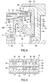
- the rotary cup 4 includes an annular eaves portion 31 inclined to extend inward and upward from a position above the end of the rotary plate 11 and a cylindrical outer wall portion 32 extending vertically downward from the outer end of the eaves portion 31. As shown in the enlarged view of FIG. 4, an annular gap 33 is formed between the outer wall portion 32 and rotary plate 11, so that a process liquid (mist) scattered by rotation of the wafer W along with the rotary plate 11 and rotary cup 4 is guided downward through the gap 33.
- a process liquid (mist) scattered by rotation of the wafer W along with the rotary plate 11 and rotary cup 4 is guided downward through the gap 33.
- a plate-like guide member 35 is disposed between the eaves portion 31 and rotary plate 11 at a height essentially the same as the wafer W.
- a plurality of spacers 38 and 39 are disposed in an annular direction between the eaves portion 31 and guide member 35 and between the guide member 35 and rotary plate 11 to form openings 36 and 37 for allowing the process liquid to pass therethrough.
- the eaves portion 31, guide member 35, rotary plate 11, and spacers 38 and 39 are fixed to each other by screws 40.
- the guide member 35 is arranged such that the upper and lower surfaces thereof are to be almost continued to the front and back surfaces of the wafer W.
- a process liquid is supplied onto the center of the front surface of the wafer W from the front surface process liquid supply nozzle 5 while the wafer holding member 2 and rotary cup 4 are rotated along with the wafer W by the motor 3, the process liquid is spread by a centrifugal force on the front surface of the wafer W and is thrown off from the peripheral edge of the wafer W.
- the process liquid thus thrown off from the front surface of the wafer W is guided by the upper surface of the guide member 35 almost continued thereto. Then, the process liquid is discharged outward through the openings 36, and is guided downward by the outer wall portion 32.
- the guide member 35 since the process liquid thrown off from the front and back surfaces of the wafer W is guided by the guide member 35, the process liquid separated from the peripheral edge of the wafer W can hardly become turbulent. In this case, it is possible to guide the process liquid out of the rotary cup 4 while preventing the process liquid from being turned into mist. As shown in FIG. 2, the guide member 35 has notches 41 at positions corresponding to the wafer holding accessories 14 to accept the wafer holding accessories 14.
- the rotary plate 11, rotary cup 4, spacers 38 and 39, screws 40, guide member 35, and so forth are made of a synthetic resin, such as PEEK, PTFE, PVC, PFA, or PVDF, in light of a chemical resistance or the like.
- the exhaust/drain section 7 is mainly used for collecting exhaust gas and drainage discharged from the space surrounded by the rotary plate 11 and rotary cup 4.
- the exhaust/drain section 7 includes an annular drain cup 51 disposed to receive the process liquid discharged from the rotary cup 4, and an annular exhaust cup 52 accommodating the drain cup 51 and disposed coaxially with the drain cup 51.
- the drain cup 51 and annular exhaust cup 52 are made of a synthetic resin, such as PEEK, PTFE, PVC, PFA, or PVDF, in light of a chemical resistance or the like, as in the rotary cup 4.
- the drain cup 51 includes a cylindrical vertical wall 53 disposed outside the rotary cup 4 adjacent to the outer wall portion 32, and a lower side portion 54 extending inward from the lower end of the vertical wall 53.
- the lower side portion 54 is connected to a vertical inner wall 54a on the inner side.
- the vertical wall 53 and lower side portion 54 define an annular space used as a process liquid receptacle 56 for receiving the process liquid discharged from the rotary cup 4.
- the upper side of the vertical wall 53 is formed as an extending portion 53a extending to a position above the rotary cup 4 to prevent the process liquid from bouncing out from the drain cup 51.
- the process liquid receptacle 56 includes an annular partition wall 55 disposed therein in an annular direction of the drain cup 51 outside the holding accessory 14 and extending from the lower side portion 54 to a position near the lower surface of the rotary plate 11.
- the process liquid receptacle 56 is divided by the partition wall 55 into a main cup portion 56a and an auxiliary cup portion 56b.
- the main cup portion 56a is used for receiving the process liquid discharged from the gap 33, while the auxiliary cup portion 56b is used for receiving the process liquid dropping from portions near the holding portions 14a of the holding accessories 14.
- the bottom surface 57 of the process liquid receptacle 56 is divided by the partition wall 55 into a first portion 57a corresponding to the main cup portion 56a and a second portion 57b corresponding to the auxiliary cup portion 56b.
- the first and second portions 57a and 57b are inclined upward and inward (toward the rotational center).
- the inner side of the second portion 57b extends inward (toward the rotational center) further from a position corresponding to the holding portions 14a of the holding accessories 14.
- the partition wall 55 serves to prevent stray winds, generated by the portions of the holding accessories 14 protruding downward below the rotary plate 11, from involving and transferring mist onto the wafer W.
- the partition wall 55 has a hole 58 formed therein to guide the process liquid from the auxiliary cup portion 56b to the main cup portion 56a (see FIG. 1).
- the drain cup 51 includes an annular (flange-like) fixing section 72 at the bottom on the inner peripheral side to fix the drain cup 51 to the bottom of the exhaust cup 52.
- the fixing section 72 includes two positioning portions 73 and four screwed portions 74.
- the positioning portions 73 have synthetic resin positioning pins 73a inserted into recesses formed in the exhaust cup 52 to position the drain cup 51 relative to the exhaust cup 52.
- the screwed portions 74 are fixed to the exhaust cup 52 by synthetic resin screws 75.
- a plurality of spacers 76 are disposed between the positioning portions 73 and screwed portions 74, so that gaps 77 are formed between the fixing section 72 and exhaust cup 52 by the spacers 76 uniformly all over an annular direction.
- the numbers of positioning portions 73 and screwed portions 74 are not limited to the examples described above, although each of them needs to be two or more.
- a portion of the drain cup 51 below the lower side portion 54 is removed or recessed from below to form a bore portion 59 below the lower side portion 54 and outside the fixing section 72.
- This bore portion 59 is formed to define a flexible thin cylindrical portion 79 extending upward from the fixing section 72.
- the cylindrical portion 79 has a thickness of about 3 to 6 mm.
- the bore portion 59 further defines an annular buffer space 78 located coaxially with the drain cup 51 within the exhaust cup 52 and connected to exhaust ports 70, as described later.
- the drain cup 51 which is made of a synthetic resin and thus inherently has a large coefficient of thermal expansion, is arranged such that the inner peripheral side is fixed by the fixing section 72, while the outer peripheral side where large thermal expansion can be caused is not fixed. Consequently, when the drain cup 51 receives a high temperature process liquid discharged therein and thereby causes thermal expansion, it is unlikely that the drain cup 51 is damaged by the thermal expansion.
- the fixing section 72 is located on the inward side from the process liquid receptacle 56, so that the fixing section 72 is thus less thermally affected by the high temperature process liquid.
- the flexible thin cylindrical portion 79 serves to suppress thermal effect on the fixing section 72 and also serves to flexibly absorb deformation of the drain cup 51 due to thermal expansion, when the high temperature process liquid is used. Consequently, the screws 75 and so forth used in the fixing section 72 of the drain cup 51 are prevented from being damaged by thermal expansion due to the process liquid.
- the drain cup 51 has a drain port 60 for drainage from the process liquid receptacle 56, which is formed in the lower side portion 54 at one position on the outermost side and connected to a drain tube 61 (see FIG. 1).
- the drain tube 61 is connected to a drain-switching member (not shown), so that process liquids are separately collected or discarded in accordance with the types thereof.
- a plurality of drain ports 60 may be formed.
- the exhaust cup 52 includes an outer wall 64 vertically extending outside the vertical wall 53 of the drain cup 51, and an inner wall 65 disposed on the inward side from the holding accessories 14 and vertically extending to have an upper end adjacent to the rotary plate 11.
- the exhaust cup 52 further includes a bottom wall 66 placed on the base plate 1, and an upper wall 67 extending upward and curved from the outer wall 64 to cover an area above the rotary cup 4.
- the exhaust cup 52 is mainly used for collecting and exhausting gas components from inside and around the rotary cup 4 through an annular inlet port (upper exhaust inlet port) 68 formed between the upper wall 67 and eaves portion 31 of the rotary cup 4. As shown in FIGS.
- the exhaust cup 52 has exhaust ports 70 formed in the bottom and each connected to an exhaust tube 71.
- the exhaust tube 71 is connected to a suction mechanism (not shown) on the downstream side, so that gas is exhausted from around the rotary cup 4.
- the plurality of exhaust ports 70 can be selectively used by switching in accordance with the types of process liquids.
- a single exhaust port may be used and connected to an exhaust tube, which is branched on the downstream side into a plurality of exhaust lines switchable in accordance with the types of process liquids.
- the annular buffer space 78 is defined above the exhaust ports 70 by the bore portion 59 of the drain cup 51, and is located coaxially with the drain cup 51 within the exhaust cup 52.
- at least one exhaust port 70 is formed directly below the buffer space 78 and is directly connected to the buffer space 78.
- an outer annular space 99a is formed between the outer wall or vertical wall 53 of the drain cup 51 and the outer wall 64 of the exhaust cup 52.
- An annular gas flow adjusting member (gas-flow resistance portion) 97 is disposed between the bottom of the drain cup 51 and the bottom of the exhaust cup 52 outside the exhaust ports 70.
- the gas flow adjusting member 97 has a number of gas-flow holes 98 in an annular direction and is arranged to apply a predetermined gas-flow resistance to the exhaust gas flow from the inlet port (upper exhaust inlet port) 68 of the exhaust cup 52.
- the inlet port 68 is connected to the annular buffer space 78 through the outer annular space 99a and gas flow adjusting member 97 all over an annular direction.
- This structure serves as a gas-flow adjusting mechanism for adjusting the gas flow of gas components collected in the exhaust cup 52 and uniformly discharging it from the exhaust ports 70.
- this exhaust gas flow is guided downward through the annular space or outer annular space 99a uniformly all over an annular direction, and is then supplied with a pressure loss or resistance by the gas flow adjusting member 97 having a number of gas-flow holes 98, so that the gas flow is introduced into the buffer space 78 in a distributed state. Since the buffer space 78 provides a space having a sufficient capacity all over an annular direction above the exhaust ports 70 within the exhaust cup 52, the pressure loss applied to the gas flow is small (the resistance against the gas flow is small) even at positions remote from the exhaust ports 70 (positions across the exhaust ports 70).
- the gas flow within the exhaust cup 52 is prevented from being localized, so that the gas flow is relatively uniformly discharged to the exhaust ports 70 from all around, regardless of the distance from the exhaust ports 70.
- the gas flow is preferentially discharged only from around the exhaust ports 70, while it is hardly discharged from positions remote from the exhaust ports 70.
- the exhaust cup 52 is arranged to further collect and discharge gas components below the wafer holding member 2.
- an inner annular space 99b is formed between the inner wall 54a of the drain cup 51 and the inner wall 65 of the exhaust cup 52.
- the gaps 77 are formed between the fixing section 72 and the exhaust cup 52 by the spacers 76 on the inner peripheral side of the drain cup 51 uniformly all over an annular direction to apply a predetermined gas-flow resistance to the exhaust gas flow.
- This structure also serves as a gas-flow adjusting mechanism for adjusting the gas flow of gas components collected in the exhaust cup 52 and uniformly discharging it from the exhaust ports 70. Consequently, the exhaust gas flow from the process liquid receptacle 56 is guided through the inner annular space 99b and gaps 77, and is introduced into the annular buffer space 78 uniformly all over an annular direction, so that the gas flow is relatively uniformly discharged to the exhaust ports 70 from all around.
- the portion between the gas flow adjusting member 97 and the bottom of the drain cup 51 on the outer peripheral side is not fixed but slidable.
- the drain cup 51 is arranged such that the inner peripheral side is fixed to the exhaust cup 52 by the fixing section 72, while the bottom on the outer peripheral side is not fixed but slidable in the radial direction on the bottom of the exhaust cup 52. Consequently, as described previously, when the drain cup 51 receives a high temperature process liquid, it can be thermally expanded on the outer peripheral side without being restrained.
- the process liquid is guided by the rotary cup 4 to the drain cup 51, and gas components are guided from the inlet port 68 to the exhaust cup 52.
- the liquid-draining from the drain cup 51 is performed independently of the gas-exhausting from the exhaust cup 52, so that drainage and exhaust gas are guided separately from each other.
- the exhaust cup 52 is disposed to surround the drain cup 51, mist leaked out of the drain cup 51 is swiftly discharged from the exhaust ports 70, so that the mist is reliably prevented from diffusing outside.
- FIGS. 7A to 7D an explanation will be given, with reference to FIGS. 7A to 7D, of an operation of the liquid processing apparatus 100 having the structure described above.
- the elevating member 13 is set at the upper position, and a wafer W is transferred from a transfer arm (not shown) onto the support pins 25 of the wafer support head 24.
- the elevating member 13 is moved down to a position where the wafer W can be held by the holding accessories 14, and then the wafer W is chucked by the holding accessories 14.
- FIG. 7C the front surface process liquid supply nozzle 5 is moved from the retreat position to the wafer cleaning position.
- the process liquid is supplied from the front surface process liquid supply nozzle 5 and back surface process liquid supply nozzle 6 onto the front surface and back surface of the wafer W, and is spread by a centrifugal force outward on the wafer W and thrown off from the peripheral edge of the wafer W.
- the cup surrounding the wafer W used in this wafer cleaning process is the rotary cup 4 that is rotated along with the wafer W. Accordingly, when the process liquid thrown off from the wafer W hits against the rotary cup 4, a centrifugal force acts on the process liquid, and the process liquid is thereby inhibited from being scattered (turned into mist), unlike a case where a stationary cup is used for the same purpose. Then, the process liquid is guided downward by the rotary cup 4, and is discharged through the gap 33 into the main cup portion 56a of the drain cup 51. Further, since the rotary plate 11 has holes for inserting the holding portions 14a at positions where the holding accessories 14 are attached, the process liquid drops through the holes into the auxiliary cup portion 56b of the drain cup 51.
- the process liquid thus received by the drain cup 51 is discharged from the drain port 60 through the drain tube 61. Further, gas components are collected from inside and around the rotary cup 4 into the exhaust cup 52 through the annular inlet port 68 formed between the upper wall 67 and the eaves portion 31 of the rotary cup 4, and are discharged from the exhaust ports 70 through the exhaust tubes 71.
- the drain cup 41 can be smaller as long as it is usable for draining.
- the drain cup 51 and exhaust cup 52 are independent of each other such that exhaust gas and drainage are separately collected and separately discharged through the drain port 60 and exhaust ports 70. Accordingly, there is no need to dispose a special mechanism for separating drainage and exhaust gas.
- the drain cup 51 is accommodated within the exhaust cup 52. Consequently, the structure for collecting exhaust gas and drainage can be arranged to have a smaller occupation space, so the apparatus can be compact with a small foot print. Furthermore, since the drain cup 51 is accommodated within the exhaust cup 52, it is possible to trap mist of the process liquid leaked out of the drain cup 51, thereby preventing the mist from exerting a bad influence while being scattered out of the apparatus.
- the gas flow is preferentially discharged only from around the exhaust ports 70, while it is hardly discharged from positions remote from the exhaust ports 70.
- the gas flow is guided downward through the outer annular space 99a uniformly all over an annular direction, and is then supplied with a pressure loss or resistance by the gas-flow holes 98 of the gas flow adjusting member 97, so that the gas flow is introduced into the buffer space 78 in a distributed state. Consequently, the gas flow within the exhaust cup 52 is prevented from being localized, so that the gas flow is relatively uniformly discharged to the exhaust ports 70 from all around, regardless of the distance from the exhaust ports 70.
- gas components collected through the inlet port 68 slightly flow into the process liquid receptacle 56 of the drain cup 51, as well as the outer annular space 99a, and then flow through the inner side of the drain cup 51 to the exhaust ports 70.
- the inner annular space 99b is formed between the vertical inner wall 54a of the drain cup 51 on the inner side and the inner wall 65 of the exhaust cup 52.
- the gaps 77 are formed between the fixing section 72 and the exhaust cup 52 on the inner peripheral side of the drain cup 51.
- the gas flow is guided downward through the process liquid receptacle 56 and inner annular space 99b uniformly all over an annular direction, and is then supplied with a resistance by the gaps 77, so that the gas flow is introduced into the buffer space 78 in a distributed state. Consequently, the gas flow within the exhaust cup 52 is prevented from being localized, so that the gas flow is relatively uniformly discharged to the exhaust ports 70 from all around, regardless of the distance from the exhaust ports 70.
- This gas flow through the inner annular space 99b to the exhaust ports 70 is smaller than the gas flow through the outer annular space 99a to the exhaust ports 70. Accordingly, the inner annular space 99b and gaps 77 suffice for making the gas flow uniform without using the gas flow adjusting member 97 as in the outer side.
- a process liquid such as SC1 may be used at a high temperature of, e.g., about 80°C.
- SC1 a process liquid
- the annular drain cup 51 made of a synthetic resin receives this process liquid, the drain cup 51 causes large thermal expansion due to the high temperature, and is particularly expanded on the outer peripheral side.
- the drain cup 51 is structured to receive large thermal expansion by a fixing section, such as a case where the outer peripheral side of the drain cup is fixed, this fixing section may be damaged by the thermal expansion.
- the fixing section 72 of the drain cup 51 is located only at the bottom on the inner peripheral side, while no fixing section is present on the outer peripheral side where large thermal expansion can be caused.
- the bottom on the outer peripheral side is not fixed but slidable in the radial direction on the gas flow adjusting member 97, so it is unlikely that the drain cup 51 is damaged by the thermal expansion.
- the fixing section 72 is located on the inward side from the process liquid receptacle 56, so that the fixing section 72 is thus less thermally affected by the high temperature process liquid.
- the flexible thin cylindrical portion 79 serves to suppress heat transmission to the fixing section 72 and also serves to flexibly absorb deformation of the drain cup 51 due to thermal expansion, when the high temperature process liquid is used. Consequently; the screws 75 and so forth used in the fixing section 72 of the drain cup 51 are reliably prevented from being damaged by thermal expansion due to the process liquid.
- the rotary cup since the rotary cup is rotated along with the substrate, a centrifugal force acts on the rotary cup, so mist of the process liquid is inhibited from bouncing back, unlike a case where a stationary cup is used for the same purpose.
- the annular drain cup is disposed around the rotary cup,'and the exhaust cup is disposed to accommodate the drain cup coaxially therewith.
- the drain cup can be more compact because the rotary cup prevents mist from bouncing back while the drain cup is accommodated in the exhaust cup. Consequently, it is possible to make the occupation space of the drain cup smaller, thereby providing the apparatus with a small foot print. Further, since the liquid-draining from the drain cup is performed independently of the gas-exhausting from the exhaust cup, there is no need to dispose a special mechanism for separating drainage and exhaust gas.
- the gas-flow adjusting mechanism is disposed to adjust a flow of gas components collected in the exhaust cup to be formed toward the exhaust ports from essentially all around. Consequently, the exhaust gas within the exhaust cup can be uniformly discharged all over an annular direction.
- the drain cup is fixed to the exhaust cup by the fixing section on the inner peripheral side, while it is not fixed on outer peripheral side that can be affected by thermal expansion. Consequently, even when the drain cup is expanded due to a high temperature process liquid, the drain cup can be hardly damaged by thermal expansion
- FIG. 9 is a sectional view schematically showing the structure of a liquid processing apparatus according to an embodiment of the present invention.
- FIG. 10 is a plan view thereof, and
- FIG. 11 is an enlarged sectional view of an exhaust/drain section.
- This liquid processing apparatus 300 includes a base plate 201 and a wafer holding member 202 for rotatably holding a target substrate or wafer W.
- the wafer holding member 202 is rotatable by a rotary motor 203.
- a rotary cup 204 is disposed around the wafer W held on the wafer holding member 202 and configured to rotate along with the wafer holding member 202.
- the liquid processing apparatus 300 further includes a front surface process liquid supply nozzle 205 for supplying a process liquid onto the front surface of the wafer W, and a back surface process liquid supply nozzle 206 for supplying a process liquid onto the back surface of the wafer W.
- an exhaust/drain section 207 is disposed around the rotary cup 204.
- a casing 208 is disposed to cover the area around the exhaust/drain section 207 and the area above the wafer W.
- the casing 208 is provided with a fan/filter unit (FFU) 209 at the top, so that clean air is supplied as a down flow onto the wafer W held on the wafer holding member 202.
- FFU fan/filter unit
- the wafer holding member 202 includes a rotary plate 211 formed of a circular plate set in a horizontal state.
- the center of the bottom of the rotary plate 211 is connected to a cylindrical rotary shaft 212 extending vertically downward.
- the rotary plate 211 has a circular opening 211a at the center, which communicates with a bore 212a formed inside the rotary shaft 212.
- An elevating member 213 supporting the back surface process liquid supply nozzle 206 is movable up and down through the bore 212a and opening 211a.
- the rotary plate 211 is provided with three holding accessories (accessories for holding the wafer) 214 disposed at regular intervals for holding the outer edge of the wafer W.
- the holding accessories 214 are configured to hold the wafer W in a horizontal state such that the wafer W is slightly separated from the rotary plate 211.
- Each of the holding accessories 214 includes a holding portion 214a configured to hold the edge of the wafer W, an operation lever 214b extending from the holding portion 214a toward the center of the lower surface of the rotary plate, a pivot shaft 214c that supports the holding portion 214a to be vertically rotatable, and a shaft support portion 214d that holds the pivot shaft 214c.
- a cylinder mechanism not shown
- Each holding accessory 214 is biased by a spring (not shown) toward a direction for the holding portion 214a to hold the wafer W, so that the holding accessory 214 can hold the wafer W when the cylinder mechanism does not act thereon.
- the rotary shaft 212 is rotatably supported by the base plate 201 through a bearing mechanism 215 having two bearings 215a and 215b.
- the rotary shaft 212 is provided with a pulley 216 fitted thereon at the lower end.
- the shaft of the motor 203 is also provided with a pulley 218 fitted thereon.
- a belt 217 is wound around between these pulleys 216 and 218.
- the rotary shaft 212 is rotated through the pulley 218, belt 217, and pulley 216 by rotation of the motor 203.
- An annular purge gas supply port 219 is disposed directly above the bearing mechanism 215 to surround the outer surface of the rotary shaft 212.
- the purge gas supply port 219 is connected to a purge gas passage 220 formed in the outer wall of the bearing mechanism 215 and extends in a vertical direction.
- the purge gas passage 220 is connected to a purge gas tube 221 at a position below the base plate 201 of the bearing mechanism 215.
- a purge gas such as N 2 gas, is supplied from a purge gas supply source (not shown) through the purge gas tube 221 and purge gas passage 220 to the purge gas supply port 219. Then, the purge gas is supplied from the purge gas supply port 219 and flows upward and downward along the rotary shaft 212.
- the purge gas delivered upward from the purge gas supply port 219 flows into a space S1 defined by a partition wall 265 around the rotary shaft 212, and sets this space S1 at a positive pressure.
- the positive pressure blocks the inflow of mist or process liquid from a space S2 outside the partition wall 265 where a chemical atmosphere is formed by various process liquid components. Consequently, the mist or process liquid is prevented from being deposited on the upper side of the rotary shaft 212 made of a metal that can be easily corroded, so that the rotary shaft 212 is protected from corrosion.
- the purge gas delivered downward from the purge gas supply port 219 flows around the upper and lower bearings 215a and 215b inside the bearing member 215, and is then exhausted outside from the apparatus.
- This flow carries particles, generated due to abrasion of the bearings 215a and 215b, out of the apparatus. Consequently, the particles generated from the bearings 215a and 215b are prevented from reaching the wafer W.
- the front surface process liquid supply nozzle 205 is supported by a nozzle arm 222.
- a process liquid is supplied through a liquid supply tube (not shown) into the nozzle 205 and is then delivered from a nozzle hole 205a formed in the nozzle 205.
- the process liquid thus delivered encompasses a cleaning chemical solution, a rising liquid such as purified water, and a drying solvent such as IPA.
- the nozzle 205 is configured to selectively deliver process liquids of one, two, or more types. As shown in FIG.
- the nozzle arm 222 is rotatable about a shaft 223 used as a central axis, and is movable by a driving mechanism (not shown) between a delivery position above the center of the wafer W and a retreat position outside the wafer W. Further, the nozzle arm 222 is movable up and down, such that the arm 222 is set at an upper position when it is rotated between the retreat position and delivery position, and at a lower position when a process liquid is delivered from the front surface process liquid supply nozzle 205.
- the back surface process liquid supply nozzle 206 has a nozzle hole 206a formed through the center of the elevating member 213 and extending in the longitudinal direction.
- a predetermined process liquid is supplied through a process liquid tube (not shown) into the nozzle hole 206a from below and is then delivered from the nozzle hole 206a onto the back surface of the wafer W.
- the process liquid thus delivered encompasses a cleaning chemical solution, a rising liquid such as purified water, and a drying solvent such as IPA, as in the front surface process liquid supply nozzle 205.
- the nozzle 206 is configured to selectively deliver process liquids of one, two, or more types.
- the elevating member 213 includes a wafer support head 224 at the top for supporting the wafer W.
- the wafer support head 224 is provided with three wafer support pins 225 for supporting the wafer W '(only two of them are shown) on the upper surface.
- the lower end of the back surface process liquid supply nozzle 206 is connected to a cylinder mechanism 227 through a connector 226.
- the elevating member 213 is movable up and down by the cylinder mechanism 227 to move up and down the wafer W for loading and unloading the wafer W.
- the rotary cup 204 includes an annular eaves portion 231 inclined to extend inward and upward from a position above the end of the rotary plate 211 and a cylindrical outer wall portion 232 extending vertically downward from the outer end of the eaves portion 231.
- An annular gap 233 is formed between the outer wall portion 232 and rotary plate 211, so that a process liquid (mist) scattered by rotation of the wafer W along with the rotary plate 211 and rotary cup 204 is guided downward through the gap 233.
- a plate-like guide member 235 is disposed between the eaves portion 231 and rotary plate 211 at a height essentially the same as the wafer W. As shown in FIG. 12, a plurality of spacers 238 and 239 are disposed in an annular direction between the eaves portion 231 and guide member 235 and between the guide member 235 and rotary plate 211 to form openings 236 and 237 for allowing the process liquid to pass therethrough.
- the eaves portion 231, guide member 235, rotary plate 211, and spacers 238 and 239 are fixed to each other by screws 40.
- the guide member 235 is arranged such that the upper and lower surfaces thereof are to be almost continued to the front and back surfaces of the wafer W.
- a process liquid is supplied onto the center of the front surface of the wafer W from the front surface process liquid supply nozzle 205 while the wafer holding member 202 and rotary cup 204 are rotated along with the wafer W by the motor 203, the process liquid is spread by a centrifugal force on the front surface of the wafer W and is thrown off from the peripheral edge of the wafer W.
- the process liquid thus thrown off from the front surface of the wafer W is guided by the upper surface of the guide member 235 almost continued thereto.
- the process liquid is discharged outward through the openings 236, and is guided downward by the eaves portion 231 and outer wall portion 232.
- the process liquid is spread by a centrifugal force on the back surface of the wafer W and is thrown off from the peripheral edge of the wafer W.
- the process liquid thus thrown off from the back surface of the wafer W is guided by the lower surface of the guide member 235 almost continued thereto.
- the process liquid is discharged outward through the openings 237, and is guided downward by the eaves portion 231 and outer wall portion 232.
- a centrifugal force acts on the process liquid guided to the spacers 238 and 239 and outer wall portion 232, mist of the process liquid is inhibited from returning inward.
- the guide member 235 since the process liquid thrown off from the front and back surfaces of the wafer W is guided by the guide member 235, the process liquid separated from the peripheral edge of the wafer W can hardly become turbulent. In this case, it is possible to guide the process liquid out of the rotary cup while preventing the process liquid from being turned into mist. As shown in FIG. 10, the guide member 235 has notches 41 at positions corresponding to the holding accessories 214 to accept the holding accessories 214.
- the exhaust/drain section 207 is mainly used for collecting exhaust gas and drainage discharged from the space surrounded by the rotary plate 211 and rotary cup 204. As shown in the enlarged view of FIG. 11, the exhaust/drain section 207 includes an annular drain cup 251 disposed to receive the process liquid discharged from the rotary cup 204, and an annular exhaust cup 252 disposed outside the drain cup 251 to surround the drain cup 251.
- the drain cup 251 includes a vertical wall 253 disposed outside the rotary cup 204 adjacent to the outer wall portion 232, and a bottom portion 254 extending inward from the lower end of the vertical wall 253.
- the upper side of the vertical wall 253 extends to a position above the outer wall portion 232 of the rotary cup 204 and is curved along the eaves portion 231. This arrangement is conceived to prevent mist from flowing backward from inside the drain cup 251 toward the wafer W.
- the bottom portion 254 of the annular drain cup 251 is inclined upward and inward (toward the rotational center of the wafer W).
- the inner side of the bottom portion 254 extends inward (toward the rotational center) further from a position corresponding to the holding portions 214a of the holding accessories 214.
- the drain cup 251 is provided with an annular (cylindrical) shielding wall 255 disposed therein in an annular direction outside the holding accessories 214 and extending from the bottom portion 254 to a position near the lower surface of the rotary plate 211.
- the shielding wall 255 serves to prevent stray winds, generated in the space S2 below the rotary plate 211, from flowing outward relative to the drain cup 251 (in a direction away from the rotary shaft 212).
- the interior of the drain cup 251 is divided by the shielding wall 255 into a main liquid receiving portion 256 and an auxiliary liquid receiving portion 257.
- the main liquid receiving portion 256 is used for receiving the process liquid discharged from the gap 233, while the auxiliary liquid receiving portion 257 is used for receiving the process liquid dropping from portions near the holding portions 214a of the holding accessories 214.
- the shielding wall 255 also serves as a separator (partition wall) to partition the two liquid receiving portions for receiving the process liquid.
- the holding portions 214a of the holding accessories 214 are rotatable about the pivot shaft 214c used as the rotational center to hold the wafer W and cancel the hold on the wafer W, so the rotary plate 211 has holes 211b for inserting the holding portions 214a.
- the process liquid flows through the holes 211b of the rotary plate 211 to the back side (lower surface) of the rotary plate 211, and drops downward into the auxiliary liquid receiving portion 257.
- the shielding wall 255 has a hole 258 formed therein as a communication port to guide the process liquid from the auxiliary liquid receiving portion 257 to the main liquid receiving portion 256.
- the drain cup 251 has a drain port 260 formed in the bottom portion 254 at one position on the outermost side and connected to a drain tube 261.
- the drain tube 261 is connected to a suction mechanism through a drain-switching member (both not shown), so that process liquids are separately collected or discarded in accordance with the types thereof.
- a drain-switching member both not shown
- a plurality of drain ports 260 may be formed in accordance with the types of process liquids.
- the exhaust cup 252 includes an outer wall 264 vertically extending outside the vertical wall 253 of the drain cup 251, and a partition wall 265 disposed on the inward side from the holding accessories 214 and vertically extending to have an upper end adjacent to the rotary plate 211.
- the exhaust cup 252 further includes a bottom wall 266 placed on the base plate 201, and a top wall 267 extending upward and curved from the outer wall 264 to cover an area above the rotary cup 204.
- the partition wall 265 serves as a wall for separating the atmosphere in the inner side space S1 around the rotary shaft 212 from that in the outer side space S2.
- the exhaust cup 252 is mainly used for collecting and exhausting gas components from inside and around the rotary cup 204 through an annular inlet port 268 formed between the upper wall 267 and eaves portion 231 of the rotary cup 204.
- the exhaust cup 252 has exhaust ports 70 formed in the bottom and each connected to an exhaust tube 71.
- the exhaust tube 71 is connected to a suction mechanism (not shown) on the downstream side, so that gas is exhausted from around the rotary cup 204.
- the plurality of exhaust ports 70 can be selectively used by switching in accordance with the types of process liquids.
- the process liquid is guided by the rotary cup 204 to the drain cup 251, and gas components are guided from the inlet port 268 to the exhaust cup 252.
- the liquid-draining from the drain cup 251 is performed independently of the gas-exhausting from the exhaust cup 252, so that drainage and exhaust gas are guided separately from each other.
- the exhaust cup 252 is disposed to surround the drain cup 251, mist leaked out of the drain cup 251 is swiftly discharged from the exhaust port 70, so that the mist is reliably prevented from diffusing outside.
- the bottom portion 254 of the drain cup 251 is inclined upward and inward (toward the rotational center). Accordingly, the inside bottom surface 254a of the main liquid receiving portion 256 and the inside bottom surface 254b of the auxiliary liquid receiving portion 257 are also inclined upward and inward (toward the rotational center).
- the auxiliary liquid receiving portion 257 is set to be shallower than the main liquid receiving portion 256. This arrangement relates to the amount of process liquid received by the main liquid receiving portion 256 and auxiliary liquid receiving portion 257.
- the amount of process liquid flowing through the holes 211b of the rotary plate 211 to the back side (lower surface) is smaller than that of the amount of process liquid received by the main liquid receiving portion 256, so the main liquid receiving portion 256 is preferably set to have a volume larger than that of the auxiliary liquid receiving portion 257.
- the shielding wall 255 serves to prevent stray winds (for example, a circular current), generated by the portions of the holding accessories 214 protruding downward below the rotary plate 211, from involving and transferring mist onto the wafer W.
- stray winds for example, a circular current
- each of the holding accessories 214 extends from the holding portion 214a to the operation lever 214b on the opposite side while protruding downward toward the center of the lower surface of the rotary plate 211.
- the holding accessories 214 act as fins and generate stray winds in the space below the rotary plate 211.
- the stray winds thus generated may disturb exhaust gas flowing in one direction toward exhaust ports 270 within the exhaust cup 252. Consequently, mist contained in the exhaust gas may diffuse and generate water marks and/or particles on the front surface of the wafer W.
- the cylindrical shielding wall 255 is disposed to surround the holding accessories 214 and prevent stray winds, generated by rotational movement of the holding accessories 214 along with the rotary plate 211, from heading outward in the radial direction thereby disturbing the normal exhaust gas flow.
- the drain cup 251 preferably covers a range from the outer peripheral side of the rotary plate 211 to a position directly below the holes 211b of the rotary plate 211. Accordingly, the process liquid receiving portion (concave) of the drain cup 251 is expanded inward, but this expanded concave may be therefore affected by stray winds generated in the space below the rotary plate 211.
- the drain cup 251 is provided with the shielding wall 255 to divide the process liquid receiving portion of the drain cup 251 into the main liquid receiving portion 256 and auxiliary liquid receiving portion 257.
- This arrangement prevents the stray winds generated as described above from disturbing the process liquid flowing within the main liquid receiving portion 256 of the drain cup 251, so as to prevent mist generation and to maintain the normal drainage flow.
- the main liquid receiving portion 256 and auxiliary liquid receiving portion 257 of the drain cup 251 partitioned by the shielding wall 255 are grooves (annular concaves) each essentially having a V-shape in a cross section.
- These grooves respectively have the drain port 260 and the communication port or hole 258 formed at the bottom, so that the process liquid can be swiftly led to the drain port 260. Further, since the shielding wall 255 shields stray winds, the stray winds are prevented from reaching the exhaust routes or disturbing the normal exhaust gas flow within the exhaust cup 252.
- the shielding wall 255 thus arranged allows both of the exhaust gas within the exhaust cup 252 and the drainage within the drain cup 251 to be less affected by stray winds generated by rotation of the holding accessories 214. Consequently, it is possible to improve the efficiency of the liquid processing apparatus 300 in the gas-exhausting and liquid-draining, while suppressing mist generation and particle contamination, so as to provide the liquid processing apparatus with high reliability.
- the elevating member 213 is set at the upper position, and a wafer W is transferred from a transfer arm (not shown) onto the support pins 225 of the wafer support head 224.
- the elevating member 213 is moved down to a position where the wafer W can be held by the holding accessories 214, and then the wafer W is chucked by the holding accessories 214.
- the front surface process liquid supply nozzle 205 is moved from the retreat position to the delivery position above the center of the wafer W.
- the process liquid is supplied onto the center of the front surface and back surface of the wafer W, and is spread by a centrifugal force outward on the wafer W and thrown off from the peripheral edge of the wafer W.
- the cup surrounding the wafer W used in this process is the rotary cup 204 that is rotated along with the wafer W. Accordingly, when the process liquid thrown off from the wafer W hits against the rotary cup 204, a centrifugal force acts on the process liquid, and the process liquid is thereby inhibited from being scattered (turned into mist), unlike a case where a stationary cup is used for the same purpose.
- the process liquid is guided downward by the rotary cup 204, and is discharged through the gap 233 into the main liquid receiving portion 256 of the drain cup 251. Further, since the rotary plate 211 has holes for inserting the holding portions 214a at positions where the holding accessories 214 are attached, the process liquid drops through the holes into the auxiliary liquid receiving portion 257 of the drain cup 251.
- the drain cup 251 for receiving the process liquid needs to be annular.
- the bottom portion 254 of the drain cup 251 i.e., the inside bottom surface 254a of the main liquid receiving portion 256 and the inside bottom surface 254b of the auxiliary liquid receiving portion 257) is inclined radially inward and upward, and the process liquid discharged into the main liquid receiving portion 256 and auxiliary liquid receiving portion 257 swiftly flows to an outer side, so residual liquid can be hardly generated.
- the shielding wall 255 for shielding stray winds is disposed to block stray winds generated by the holding accessories 214 mainly when the rotary plate 211 is rotated, so as to prevent the stray winds from disturbing the process liquid flowing within the drain cup 251. Further, the shielding wall 255 prevents the stray winds from reaching the exhaust routes or disturbing the normal exhaust gas flow within the exhaust cup 252, so as to suppress diffusion of mist and/or particles.
- FIG. 14 is a sectional view schematically showing the structure of a liquid processing apparatus 301 according to a modification of the second embodiment of the present invention.
- the shielding wall 255 is disposed to extend from the bottom portion 254 of the drain cup 251 and to divide the process liquid receiving portion into the main liquid receiving portion 256 and auxiliary liquid receiving portion 257.
- a cylindrical shielding wall 255a is disposed to extend downward from the rotary plate 211.
- the shielding wall 255a is located near the outer peripheral side of the rotary plate 211 outside the holes 211b, and extends to have a lower end adjacent to the bottom portion 254c of the drain cup 251a. Accordingly, the drain cup 251a is not provided with the shielding wall 255 of the liquid processing apparatus 300 shown in FIG. 9.
- the shielding wall 255a provides essentially the same function as that of the shielding wall 255 of the liquid processing apparatus 300 shown in FIG. 9. Specifically, the shielding wall 255a serves to shield stray winds generated in the space S2, so as to prevent the stray winds from reaching the exhaust routes or disturbing the normal exhaust gas flow within the exhaust cup 252.
- the shielding wall 255a divides the process liquid receiving portion of the drain cup 251a into a main liquid receiving portion 256a and an auxiliary liquid receiving portion 257a. This arrangement prevents stray winds, generated in the space S2 by rotational movement of the holding accessories 214, from disturbing the process liquid flowing within the main liquid receiving portion 256a of the drain cup 251, so as to prevent mist generation and to maintain the normal drainage flow.
- the main liquid receiving portion 256a and auxiliary liquid receiving portion 257a of the drain cup 251 partitioned by the shielding wall 255a communicate with each other through a gap formed between the lower end of the shielding wall 255a and the bottom portion 254c of the drain cup 251a. Accordingly, the process liquid dropping into the auxiliary liquid receiving portion 257a swiftly flows downward (from a side closer to the rotational center of the wafer W) to the main liquid receiving portion 256a through the bottom portion 254c inclined toward the outer peripheral side. Then, the process liquid is swiftly led to a drain port 260 formed at the bottom of the main liquid receiving portion 256a, which is a groove (annular concave) essentially having a V-shape in a cross section.
- FIG. 15 is a perspective view showing the structure of the lower surface of the rotary plate 211.
- FIG. 16 is a sectional view showing a main portion of the rotary plate 211 including the protrusions 211c. A plurality of (three in this modification) protrusions 211c are disposed to sandwich the attaching positions P of the holding accessories 214.
- the rotary plate 211 When the rotary plate 211 is rotated, stray winds, such as a circular current, are generated in the space S2, because the portions of the relatively large holding accessories 214 protruding downward below the rotary plate 211 act as agitation fins by rotational movement. Accordingly, where the protrusions 211c are formed on the lower surface of the rotary plate 211 at positions along the same circular track as the holding accessories 214, the agitation performance of the holding accessories 214 can be attenuated to suppress generation of stray winds. In order to obtain such effect of suppressing generation of stray winds, the height "h" of the protrusions 211c is preferably set to be equal to or higher than the shaft support portions 214d of the holding accessories 214.
- the protrusions 211c may be hollow or solid, or may be formed integrally with the rotary plate 211 or separately formed and bonded to the lower surface of the rotary plate 211.
- the shielding wall 255a thus arranged on the rotary cup 211 side allows both of the exhaust gas within the exhaust cup 252 and the drainage within the drain cup 251 to be less affected by stray winds generated in the space S2 by rotation of the holding accessories 214.
- the lower surface of the rotary plate 211 is provided with means for suppressing stray winds (protrusions 211c) to attenuate the agitation performance of the holding accessories 214, so the intensity of stray winds becomes lower. Consequently, it is possible to improve the efficiency of the liquid processing apparatus 301 in the gas-exhausting and liquid-draining, while suppressing mist generation and particle contamination, so as to provide the liquid processing apparatus with high reliability.
- This means for suppressing stray winds (protrusions 211c) may be applied to the liquid processing apparatus 300 shown in FIG. 9.
- FIG. 17 is a sectional view schematically showing the structure of a liquid processing apparatus 302 according to another modification of the second embodiment of the present invention.
- a second shielding wall 273 is additionally disposed on the inward side (closer to the rotary shaft 212) from the shielding wall 255 at a position below the shielding wall 255.
- the second shielding wall 273 is formed of a cylindrical wall extending from the bottom wall 266 placed on the base plate 201. This second shielding wall 273 is located directly below the holding accessories 214 and has an upper end adjacent to the holding accessories 214.
- the second shielding wall 273 serves to prevent stray winds, generated in the space S2 by rotation of the holding accessories 214, from heading toward the drain cup 251 and the exhaust routes outside the drain cup 251.
- the distance between the shielding wall 273 and holding accessories 214 is preferably set to be smaller, as long as the shielding wall 273 does not come into contact with the holding accessories 214 being moved along a circular track.
- the second shielding wall 273 further prevents stray winds generated in the space S2 from flowing through a position below the drain cup 251 into the exhaust ports 270. If stray winds generated in the space S2 directly flow into the exhaust ports 270, the exhaust gas flow toward the exhaust ports 270 is thereby disturbed, wherein the gas flow is formed of gas components collected through the inlet port 268 between the upper wall 267 of the exhaust cup 252 and the eaves portion 231 of the rotary cup 204. In this case, mist contained in the exhaust gas may diffuse and generate water marks and/or particles on the wafer W.
- the second shielding wall 273 can eliminate such an ill effect of stray winds, thereby facilitating the normal exhaust gas flow.
- a cylinder mechanism (not shown) is disposed near the holding accessories 214 to push up the operation levers 214b of the holding accessories 214.
- the second shielding wall 273 prevents mist or process liquid from being scattered from the drain cup 251 onto the cylinder mechanism (which may cause corrosion).
- the liquid processing apparatus 302 has a double-shielding structure formed of the shielding wall 255 and the additional second shielding wall 273.
- This structure allows both of the exhaust gas within the exhaust cup 252 and the drainage within the drain cup 251 to be less affected by stray winds generated in the space S2. Consequently, it is possible to improve the efficiency of the liquid processing apparatus 302 in the gas-exhausting and liquid-draining, while suppressing mist generation and particle contamination, so as to provide the liquid processing apparatus with high reliability.
- the second shielding wall 273 of the liquid processing apparatus 302 shown in FIG. 17 may be applied to the liquid processing apparatus 301 shown in FIG. 14.
- the shielding wall is located outside the holding accessories in the radial direction relative to the rotational center of the substrate holding member for rotating the substrate held by the holding accessories.
- the shielding wall allows the exhaust gas flow and drainage flow to be less affected by stray winds generated below the substrate holding member. Consequently, it is possible to efficiently perform the gas-exhausting and liquid-draining, while suppressing generation of mist and/or particles in the liquid processing apparatus.
- the rotary cup 204 is rotated along with the rotary plate 211, but a stationary liquid receiving cup may be alternatively used to surround a wafer W held on the rotary plate 211.
- the present invention is not limited to the embodiments described above, and it may be modified in various manners.
- the embodiments described above are exemplified by a liquid processing apparatus for cleaning the front and back surfaces of a wafer.
- the present invention may be applied to a liquid processing apparatus for cleaning only one of the front surface and back surfaces of a wafer.
- the present invention may be applied to a liquid processing apparatus for performing another liquid process, such as a resist liquid coating process and/or a subsequent development process.
- the target substrate is exemplified by a semiconductor wafer, but the present invention may be applied to another substrate, such as a substrate for flat panel display devices (FPD), a representative of which is a glass substrate for liquid crystal display devices (LCD).
- FPD flat panel display devices
- LCD liquid crystal display devices
Abstract
Description
- The present invention relates to a liquid processing apparatus for performing a predetermined liquid process on a substrate, such as a semiconductor wafer.
- In the process of manufacturing semiconductor devices or flat panel display devices (FPD), liquid processes are frequently used, in which a process liquid is supplied onto a target substrate, such as a semiconductor wafer or glass substrate. For example, processes of this kind encompass a cleaning process for removing particles and/or contaminants deposited on a substrate, and a coating process for applying a photoresist liquid or development liquid in a photolithography stage.
- In general, an apparatus of this kind is arranged to supply a process liquid onto the center of a wafer, and rotate the wafer to spread the process liquid outward, thereby forming a liquid film and throwing off the process liquid. A surrounding member, such as a cup, is disposed around the wafer to guide downward the process liquid thrown off from the wafer, so that the process liquid is swiftly drained. However, where such a cup or the like is used, part of the process liquid may bounce back to the wafer as mist, and generate defects thereon, such as water marks and/or particles.
- As a technique for preventing this problem, Jpn. Pat. Appln. KOKAI Publication
No. 8-1064 Patent Document 1, the process liquid receiving member includes a horizontal eaves portion, an inclined guide portion for guiding the process liquid outward and downward, a horizontal guide portion for guiding the process liquid outward in the horizontal direction, and a wall portion extending upward in the vertical direction, in this order from the substrate side. With this arrangement, the process liquid is guided into a narrow space to prevent mist from bouncing back onto the substrate, while the process liquid is drained from a drain port formed at a corner of the process receiving member. The process liquid is then discharged through grooves extending outward within a spacer disposed around the process liquid receiving member. - However, in the case of the technique disclosed in
Patent Document 1, the process liquid is guided into a narrow space around the substrate by the process liquid receiving member that rotates along with the substrate. Accordingly, the spacer portion around the substrate needs to be larger and increases the foot print of the apparatus. Further, since exhaust gas is discharged along with drainage, it is necessary to dispose a mechanism for separating the exhaust gas and drainage on the downstream side. In order to separate exhaust gas and drainage without using a mechanism for separating them, it may be possible to separately dispose an exhaust cup and a drain cup. However, if the exhaust cup and drain cup are simply separately disposed, the foot print of the apparatus is further increased. - Where gasified components of a process liquid is exhausted from around a process liquid receiving member, it is necessary to receive the gasified components by an annular exhaust cup and discharge the gasified components smoothly and uniformly from all around through an exhaust port or exhaust ports formed at one or several positions. However,
Patent Document 1 is silent about techniques for performing such exhaust. - On the other hand, in general, a drain cup for receiving drainage is annular, made of a synthetic resin, and fixed by appropriate means. The annular drain cup receives, from a rotating process liquid receiving member, a process liquid, which may have a relatively high temperature of, e.g., 80°C. When the drain cup, made of a synthetic resin, receives such a process liquid, the drain cup is thermally expanded to a large extent. Consequently, depending on the mounting manner of the drain cup, the thermal expansion may be insufficiently absorbed, thereby damaging the drain cup.
- In the case of a liquid processing apparatus of the type that rotate a substrate held in a horizontal state, if the position of the substrate is shifted during rotation, problems, such as substrate damage, may be caused. Accordingly, there is known a substrate holding member provided with holding accessories (chuck) for holding the outer edge of the substrate, so that the substrate is reliably fixed to and integrally rotated with the substrate holding member (for example, Jpn. Pat. Appln. KOKAI Publication No. 2002-368066 (Patent Document 2: FIG. 15 and so forth)).
- In the liquid processing apparatus disclosed in Patent Document 2, the holding accessories are disposed at several positions to extend below the substrate holding member on the lower side, and respectively include portions for holding the outer edge of a substrate on the upper side. When the substrate holding member provided with these holding accessories is rotated, portions of the holding accessories extending downward from the substrate holding member generate stray winds below the substrate holding member. The stray winds may affect an exhaust gas flow below the substrate holding member and hinder mist from being discharged, thereby causing mist to bounce back to the front surface of the substrate, and generate defects thereon, such as water marks and/or particles. Further, stray winds generated below the substrate holding member may affect a drainage flow of a process liquid in a drain cup and hinder the process liquid from efficiently flowing into a drain port.
- An object of the present invention is to provide a liquid processing apparatus that requires no special mechanism for separating exhaust gas and drainage, and allows exhaust gas to be uniformly discharged all over an exhaust cup.
- Another object of the present invention is to provide a liquid processing apparatus that requires no special mechanism for separating exhaust gas and drainage, and prevents damage due to thermal expansion when a process liquid is used at a high temperature.
- Another object of the present invention is to provide a liquid processing apparatus that prevents flows of exhaust gas and/or drainage from suffering ill effects of stray winds generated below a substrate holding member for rotating a substrate held thereon in a horizontal state.
- According to a first aspect of the present invention, there is provided a liquid processing apparatus comprising: a substrate holding member configured to rotate along with a substrate held thereon in a horizontal state; a rotary cup configured to surround the substrate held on the substrate holding member, to rotate along with the substrate, and to receive the process liquid thrown off from the substrate; a rotation mechanism configured to integrally rotate the rotary cup and the substrate holding member; a liquid supply mechanism configured to supply a process liquid onto the substrate; an annular drain cup surrounding the rotary cup and configured to receive and discharge the process liquid discharged from the rotary cup; an annular exhaust cup accommodating the drain cup coaxially therewith and configured to mainly collect a gas component from inside and around the rotary cup; an exhaust port connected to the exhaust cup to discharge the gas component collected in the exhaust cup; and a gas-flow adjusting mechanism disposed between the exhaust cup and the exhaust port and configured to adjust a gas flow of the gas component to flow toward the exhaust port from essentially all around within the exhaust cup.
- In the first aspect described above, the gas-flow adjusting mechanism may comprise an annular buffer space formed coaxially with the drain cup inside the exhaust cup and connected to the exhaust port. The exhaust port may be located at least one position directly below the buffer space. The buffer space may be defined by a bottom portion of the drain cup recessed from below.
- The gas-flow adjusting mechanism may comprise an annular outer gas-flow resistance portion disposed between the drain cup and the exhaust cup and connecting an upper exhaust inlet port of the exhaust cup located above the substrate holding member to the buffer space essentially all over an annular direction, and the outer gas-flow resistance portion may be configured to apply a predetermined gas-flow resistance to an exhaust gas flow from the upper exhaust inlet port. In this case, an annular member may be disposed between the drain cup and the exhaust cup at a position corresponding to the outer gas-flow resistance portion, and the outer gas-flow resistance portion may comprise a plurality of gas-flow holes formed in the annular member uniformly all over an annular direction. An outer annular space may be formed between an outer wall of the drain cup and an outer wall of the exhaust cup and connect the upper exhaust inlet port to the outer gas-flow resistance portion.
- The gas-flow adjusting mechanism may comprise an annular inner gas-flow resistance portion disposed between the drain cup and the exhaust cup and connecting a lower exhaust inlet port of the exhaust cup located below the substrate holding member to the buffer space essentially all over an annular direction, and the inner gas-flow resistance portion may be configured to apply a predetermined gas-flow resistance to an exhaust gas flow from the lower exhaust inlet port. In this case, a plurality of spacers may be disposed between the drain cup and the exhaust cup at a position corresponding to the inner gas-flow resistance portion, and the inner gas-flow resistance portion may comprise a plurality of openings formed between the spacers uniformly all over an annular direction. An inner annular space may be formed between an inner wall of the drain cup and an inner wall of the exhaust cup and connect the lower exhaust inlet port to the inner gas-flow resistance portion.
- In the first aspect described above, the drain cup may have an inner peripheral side fixed to the exhaust cup by a fixing section and an outer peripheral side set in a non-fixed state in a radial direction. In this case, the fixing section may connect a bottom of the drain cup to a bottom of the exhaust cup. The drain cup may include a liquid receptacle for receiving the process liquid, and the fixing section may be annular and located on an inward side from the liquid receptacle. The drain cup may have an annular bore portion at a bottom outside the fixing section to define a flexible cylindrical portion extending from an upper portion of the drain cup to the fixing section. The fixing section may comprise a plurality of screwed portions and a plurality of positioning portions arrayed in an annular direction. The outer peripheral side of the drain cup may have a bottom slidably supported on bottom of the exhaust cup.
- In the first aspect described above, it may be arranged such that the substrate holding member is provided with an accessory protruding below a lower surface thereof, the drain cup includes a liquid receptacle for receiving the process liquid, and a shielding wall is disposed between the accessory and the liquid receptacle to shield a stray wind generated by the accessory. In this case, the accessory may be configured to hold the substrate on an upper end. The shielding wall may be cylindrical to surround the accessory below the substrate holding member. The shielding wall may be formed on the drain cup. The drain cup may be partitioned by the shielding wall into the liquid receptacle and a liquid receiving portion on an inward side, and the liquid receiving portion may be configured to receive the process liquid flowing onto a lower surface of the substrate holding member and connected to the liquid receptacle through a hole formed in the shielding wall.
- The shielding wall may be formed on the lower surface of the substrate holding member and extends downward. A partition wall may be disposed between a rotary shaft of the rotation mechanism and the shielding wall to separate an atmosphere around the rotary shaft from an atmosphere around the drain cup below the substrate holding member. The apparatus may further comprise a pressure adjusting mechanism configured to adjust pressure in a space partitioned by the partition wall around the rotary shaft. The apparatus may further comprise a gas supply portion configured to supply a purge gas into a space partitioned by the partition wall around the rotary shaft. A second shielding wall may be disposed directly below the accessory between the partition wall and the shielding wall to shield the stray wind. The substrate holding member may have a lower surface provided with a plurality of arc-like protrusions to suppress generation of a stray wind by the accessory, and the accessory may be located between the protrusions.
- According to a second aspect of the present invention, there is provided a liquid processing apparatus comprising: a substrate holding member configured to rotate along with a substrate held thereon in a horizontal state; a rotary cup configured to surround the substrate held on the substrate holding member, to rotate along with the substrate, and to receive the process liquid thrown off from the substrate; a rotation mechanism configured to integrally rotate the rotary cup and the substrate holding member; a liquid supply mechanism configured to supply a process liquid onto the substrate; an annular drain cup surrounding the rotary cup and configured to receive and discharge the process liquid discharged from the rotary cup; and an annular exhaust cup accommodating the drain cup coaxially therewith and configured to mainly collect and discharge a gas component from inside and around the rotary cup, wherein the drain cup has an inner peripheral side fixed to the exhaust cup by a fixing section and an outer peripheral side set in a non-fixed state in a radial direction.
- According to a third aspect of the present invention, there is provided a liquid processing apparatus comprising: a substrate holding member configured to rotate along with a substrate held thereon in a horizontal state; a rotation mechanism configured to rotate the substrate holding member; a liquid supply mechanism configured to supply a process liquid onto the substrate; and an annular drain cup surrounding the substrate holding member and configured to receive and discharge the process liquid discharged therein, wherein the substrate holding member is provided with an accessory protruding below a lower surface thereof, the drain cup includes a liquid receptacle for receiving the process liquid, and a shielding wall is disposed between the accessory and the liquid receptacle to shield a stray wind generated by the accessory.
- This summary of the invention does not necessarily describe all necessary features so that the invention may also be a sub-combination of these described features.
- The invention can be more fully understood from the following detailed description when taken in conjunction with the accompanying drawings, in which:
- FIG. 1 is a sectional view schematically showing the structure of a liquid processing apparatus according to a first embodiment of the present invention;
- FIG. 2 is a partially sectional plan view schematically showing the liquid processing apparatus according to the first embodiment of the present invention;
- FIG. 3 is a view schematically showing a process liquid supply mechanism used in the liquid processing apparatus shown in FIG. 1;
- FIG. 4 is an enlarged sectional view showing an exhaust/drain section used in the liquid processing apparatus shown in FIG. 1;
- FIG. 5 is a view for explaining the arrangement of a rotary cup and a guide member used in the liquid processing apparatus shown in FIG. 1;
- FIG. 6 is a plan view showing a fixing section for a drain cup used in the liquid processing apparatus shown in FIG. 1;
- FIGS. 7A to 7D are views for explaining an operation of the liquid processing apparatus according to the first embodiment of the present invention;
- FIG. 8 is a view schematically showing exhaust routes within an exhaust cup used in the liquid processing apparatus shown in FIG. 1;
- FIG. 9 is a sectional view schematically showing the structure of a liquid processing apparatus according to a second embodiment of the present invention;
- FIG. 10 is a partially sectional plan view schematically showing the liquid processing apparatus according to the second embodiment of the present invention;
- FIG. 11 is an enlarged sectional view showing an exhaust/drain section used in the liquid processing apparatus shown in FIG. 9;
- FIG. 12 is a view for explaining the arrangement of a rotary cup and a guide member used in the liquid processing apparatus shown in FIG. 9;
- FIGS. 13A to 13D are views for explaining an operation of the liquid processing apparatus according to the second embodiment of the present invention;
- FIG. 14 is a sectional view schematically showing the structure of a liquid processing apparatus according to a modification of the second embodiment of the present invention;
- FIG. 15 is a perspective view showing the structure of the lower surface of a rotary plate according to the modification of the second embodiment;
- FIG. 16 is a sectional view showing a main portion of a rotary plate according to the modification of the second embodiment; and
- FIG. 17 is a sectional view schematically showing the structure of a liquid processing apparatus according to another modification of the second embodiment of the present invention;
- Embodiments of the present invention will now be described with reference to the accompanying drawings. In the following description, the constituent elements having substantially the same function and arrangement are denoted by the same reference numerals, and a repetitive description will be made only when necessary. Hereinafter, an explanation will be given of a case where the present invention is applied to a liquid processing apparatus that can perform a cleaning process on the front and back surfaces of a semiconductor wafer (which will be simply referred to as "wafer", hereinafter).
- FIG. 1 is a sectional view schematically showing the structure of a liquid processing apparatus according to a first embodiment of the present invention, and FIG. 2 is a plan view thereof. FIG. 3 is a view schematically showing a process liquid supply mechanism used in the liquid processing apparatus shown in FIG. 1. FIG. 4 is an enlarged sectional view showing an exhaust/drain section used in the liquid processing apparatus shown in FIG. 1. A liquid processing system (not shown) contains a plurality of apparatuses disposed therein, each of which is the same as this
liquid processing apparatus 100. Thisliquid processing apparatus 100 includes abase plate 1 and a wafer holding member 2 for rotatably holding a target substrate or wafer W. The wafer holding member 2 is rotatable by arotary motor 3. Arotary cup 4 is disposed around the wafer W held on the wafer holding member 2 and configured to rotate along with the wafer holding member 2. Theliquid processing apparatus 100 further includes a front surface processliquid supply nozzle 5 for supplying a process liquid onto the front surface of the wafer W, and a back surface processliquid supply nozzle 6 for supplying a process liquid onto the back surface of the wafer W. Further, an exhaust/drain section 7 is disposed around therotary cup 4. Acasing 8 is disposed to cover the area around the exhaust/drain section 7 and the area above the wafer W. Thecasing 8 is provided with a gasflow inlet section 9 at the top arranged to receive through aninlet port 9a formed on a lateral side a gas flow supplied from a fan/filter unit (FFU) 9 of the liquid processing system, so that clean air is supplied as a down flow onto the wafer W held on the wafer holding member 2. - The wafer holding member 2 includes a
rotary plate 11 formed of a circular plate set in a horizontal state. The center of the bottom of therotary plate 11 is connected to a cylindricalrotary shaft 12 extending vertically downward. Therotary plate 11 has acircular opening 11a at the center, which communicates with abore 12a formed inside therotary shaft 12. An elevatingmember 13 supporting the back surface processliquid supply nozzle 6 is movable up and down through thebore 12a andopening 11a. As shown in FIG. 2, therotary plate 11 is provided with three holdingaccessories 14 disposed at regular intervals for holding the outer edge of the wafer W. The holdingaccessories 14 are configured to hold the wafer W in a horizontal state such that the wafer W is slightly separated from therotary plate 11. Each of the holdingaccessories 14 includes a holdingportion 14a configured to hold the edge of the wafer W, anoperation lever 14b extending from the holdingportion 14a toward the center of the lower surface of the rotary plate, and apivot shaft 14c that supports the holdingportion 14a to be vertically rotatable. When the distal end of theoperation lever 14b is pushed up by a cylinder mechanism (not shown), the holdingportion 14a is rotated outward and cancels the hold on the wafer W. Each holdingaccessory 14 is biased by a spring (not shown) toward a direction for the holdingportion 14a to hold the wafer W, so that the holdingaccessory 14 can hold the wafer W when the cylinder mechanism does not act thereon. - The
rotary shaft 12 is rotatably supported by thebase plate 1 through abearing mechanism 15 having twobearings 15a. Therotary shaft 12 is provided with apulley 16 fitted thereon at the lower end. The shaft of themotor 3 is also provided with apulley 18 fitted thereon. Abelt 17 is wound around between thesepulleys rotary shaft 12 is rotated through thepulley 18,belt 17, andpulley 16 by rotation of themotor 3. - The front surface process
liquid supply nozzle 5 is attached to anozzle holding member 22 supported on the distal end of anozzle arm 22a. A process liquid or the like is supplied from a processliquid supply mechanism 85 described later through a flow passage formed in thenozzle arm 22a, and is then delivered from anozzle hole 5a formed in thenozzle 5. For example, the process liquid thus delivered encompasses a chemical solution for wafer cleaning, a rising liquid such as purified water, and so forth. Thenozzle holding member 22 is further provided with a dryingsolvent nozzle 21 attached thereon for delivering a drying solvent, such as IPA. A drying solvent, such as IPA, is delivered from anozzle hole 21a formed in thenozzle 21. - As shown in FIG. 2, the
nozzle arm 22a is rotatable by adriving mechanism 81 about ashaft 23 used as a central axis to move the front surface processliquid supply nozzle 5 between wafer cleaning positions above the center and periphery of the wafer W and a retreat position outside the wafer W. Further, thenozzle arm 22a is movable up and down by an elevatingmechanism 82, such as a cylinder mechanism. - As shown in FIG. 3, the
nozzle arm 22a has aflow passage 83a formed therein and connected at one end to thenozzle hole 5a of the front surface processliquid supply nozzle 5. The other end of theflow passage 83a is connected to atube 84a. Thenozzle arm 22a further has aflow passage 83b formed therein and connected at one end to thenozzle hole 21a of the dryingsolvent nozzle 21. The other end of theflow passage 83b is connected to atube 84b. Predetermined process liquids are supplied through thetubes liquid supply mechanism 85. The processliquid supply mechanism 85 includes cleaning chemical solution sources, such as aDHF supply source 86 for supplying dilute hydrofluoric acid (DHF) as an acidic chemical solution and anSC1 supply source 87 for supplying ammonia hydrogen peroxide solution (SC1) as an alkaline chemical solution. The processliquid supply mechanism 85 further includes a rinsing liquid source, such as aDIW supply source 88 for supplying purified water (DIW) and a drying solvent source, such as anIPA supply source 95 for supplying IPA. TheDHF supply source 86,SC1 supply source 87, andDIW supply source 88 are connected totubes tubes tube 84a through switchingvalves liquid supply nozzle 5 by operating the switchingvalves tube 91 extending from theDIW supply source 88 is connected to the most upstream side of thetube 84a. On the other hand, theIPA supply source 95 is directly connected to thetube 84b extending from theflow passage 83b and provided with a switchingvalve 96 thereon. Accordingly, IPA is supplied to the dryingsolvent nozzle 21 by opening the switchingvalve 96. - The back surface process
liquid supply nozzle 6 has anozzle hole 6a formed through the center of the elevatingmember 13 and extending in the longitudinal direction. A predetermined process liquid is supplied from a process liquid supply mechanism (not shown) into thenozzle hole 6a from below and is then delivered from thenozzle hole 6a onto the back surface of the wafer W. For example, the process liquid thus delivered encompasses a cleaning chemical solution, a rising liquid such as purified water, and so forth, as in the front surface processliquid supply nozzle 5. The process liquid supply mechanism for supplying a process liquid into the back surface processliquid supply nozzle 6 may be structured as in the processliquid supply mechanism 85 except for the IPA supply circuit. The elevatingmember 13 includes awafer support head 24 at the top for supporting the wafer W. Thewafer support head 24 is provided with three wafer support pins 25 for supporting the wafer W (only two of them are shown) on the upper surface. The lower end of the back surface processliquid supply nozzle 6 is connected to acylinder mechanism 27 through aconnector 26. The elevatingmember 13 is movable up and down by thecylinder mechanism 27 to move up and down the wafer W for loading and unloading the wafer W. - The
rotary cup 4 includes anannular eaves portion 31 inclined to extend inward and upward from a position above the end of therotary plate 11 and a cylindricalouter wall portion 32 extending vertically downward from the outer end of theeaves portion 31. As shown in the enlarged view of FIG. 4, anannular gap 33 is formed between theouter wall portion 32 androtary plate 11, so that a process liquid (mist) scattered by rotation of the wafer W along with therotary plate 11 androtary cup 4 is guided downward through thegap 33. - A plate-
like guide member 35 is disposed between theeaves portion 31 androtary plate 11 at a height essentially the same as the wafer W. As shown in FIG. 5, a plurality ofspacers eaves portion 31 and guidemember 35 and between theguide member 35 androtary plate 11 to formopenings eaves portion 31,guide member 35,rotary plate 11, andspacers screws 40. - The
guide member 35 is arranged such that the upper and lower surfaces thereof are to be almost continued to the front and back surfaces of the wafer W. When a process liquid is supplied onto the center of the front surface of the wafer W from the front surface processliquid supply nozzle 5 while the wafer holding member 2 androtary cup 4 are rotated along with the wafer W by themotor 3, the process liquid is spread by a centrifugal force on the front surface of the wafer W and is thrown off from the peripheral edge of the wafer W. The process liquid thus thrown off from the front surface of the wafer W is guided by the upper surface of theguide member 35 almost continued thereto. Then, the process liquid is discharged outward through theopenings 36, and is guided downward by theouter wall portion 32. Similarly, when a process liquid is supplied onto the center of the back surface of the wafer W from the back surface processliquid supply nozzle 6 while the wafer holding member 2 androtary cup 4 are rotated along with the wafer W, the process liquid is spread by a centrifugal force on the back surface of the wafer W and is thrown off from the peripheral edge of the wafer W. The process liquid thus thrown off from the back surface of the wafer W is guided by the lower surface of theguide member 35 almost continued thereto. Then, the process liquid is discharged outward through theopenings 37, and is guided downward by theouter wall portion 32. At this time, since a centrifugal force acts on the process liquid guided to thespacers outer wall portion 32, mist of the process liquid is inhibited from returning inward. - Further, since the process liquid thrown off from the front and back surfaces of the wafer W is guided by the
guide member 35, the process liquid separated from the peripheral edge of the wafer W can hardly become turbulent. In this case, it is possible to guide the process liquid out of therotary cup 4 while preventing the process liquid from being turned into mist. As shown in FIG. 2, theguide member 35 hasnotches 41 at positions corresponding to thewafer holding accessories 14 to accept thewafer holding accessories 14. - The
rotary plate 11,rotary cup 4,spacers guide member 35, and so forth are made of a synthetic resin, such as PEEK, PTFE, PVC, PFA, or PVDF, in light of a chemical resistance or the like. - The exhaust/drain section 7 is mainly used for collecting exhaust gas and drainage discharged from the space surrounded by the
rotary plate 11 androtary cup 4. As shown in the enlarged view of FIG. 4, the exhaust/drain section 7 includes anannular drain cup 51 disposed to receive the process liquid discharged from therotary cup 4, and anannular exhaust cup 52 accommodating thedrain cup 51 and disposed coaxially with thedrain cup 51. Thedrain cup 51 andannular exhaust cup 52 are made of a synthetic resin, such as PEEK, PTFE, PVC, PFA, or PVDF, in light of a chemical resistance or the like, as in therotary cup 4. - As shown in FIGS. 1 and 4, the
drain cup 51 includes a cylindricalvertical wall 53 disposed outside therotary cup 4 adjacent to theouter wall portion 32, and alower side portion 54 extending inward from the lower end of thevertical wall 53. Thelower side portion 54 is connected to a verticalinner wall 54a on the inner side. Thevertical wall 53 andlower side portion 54 define an annular space used as a processliquid receptacle 56 for receiving the process liquid discharged from therotary cup 4. The upper side of thevertical wall 53 is formed as an extendingportion 53a extending to a position above therotary cup 4 to prevent the process liquid from bouncing out from thedrain cup 51. The processliquid receptacle 56 includes anannular partition wall 55 disposed therein in an annular direction of thedrain cup 51 outside the holdingaccessory 14 and extending from thelower side portion 54 to a position near the lower surface of therotary plate 11. The processliquid receptacle 56 is divided by thepartition wall 55 into amain cup portion 56a and anauxiliary cup portion 56b. Themain cup portion 56a is used for receiving the process liquid discharged from thegap 33, while theauxiliary cup portion 56b is used for receiving the process liquid dropping from portions near the holdingportions 14a of the holdingaccessories 14. Thebottom surface 57 of the processliquid receptacle 56 is divided by thepartition wall 55 into afirst portion 57a corresponding to themain cup portion 56a and asecond portion 57b corresponding to theauxiliary cup portion 56b. The first andsecond portions second portion 57b extends inward (toward the rotational center) further from a position corresponding to the holdingportions 14a of the holdingaccessories 14. Thepartition wall 55 serves to prevent stray winds, generated by the portions of the holdingaccessories 14 protruding downward below therotary plate 11, from involving and transferring mist onto the wafer W. Thepartition wall 55 has ahole 58 formed therein to guide the process liquid from theauxiliary cup portion 56b to themain cup portion 56a (see FIG. 1). - The
drain cup 51 includes an annular (flange-like)fixing section 72 at the bottom on the inner peripheral side to fix thedrain cup 51 to the bottom of theexhaust cup 52. As shown in FIG. 6, the fixingsection 72 includes twopositioning portions 73 and four screwedportions 74. Thepositioning portions 73 have syntheticresin positioning pins 73a inserted into recesses formed in theexhaust cup 52 to position thedrain cup 51 relative to theexhaust cup 52. The screwedportions 74 are fixed to theexhaust cup 52 by synthetic resin screws 75. A plurality ofspacers 76 are disposed between the positioningportions 73 and screwedportions 74, so thatgaps 77 are formed between the fixingsection 72 andexhaust cup 52 by thespacers 76 uniformly all over an annular direction. The numbers ofpositioning portions 73 and screwedportions 74 are not limited to the examples described above, although each of them needs to be two or more. - A portion of the
drain cup 51 below thelower side portion 54 is removed or recessed from below to form abore portion 59 below thelower side portion 54 and outside the fixingsection 72. This boreportion 59 is formed to define a flexible thincylindrical portion 79 extending upward from the fixingsection 72. Thecylindrical portion 79 has a thickness of about 3 to 6 mm. Thebore portion 59 further defines anannular buffer space 78 located coaxially with thedrain cup 51 within theexhaust cup 52 and connected to exhaustports 70, as described later. - As described above, the
drain cup 51, which is made of a synthetic resin and thus inherently has a large coefficient of thermal expansion, is arranged such that the inner peripheral side is fixed by the fixingsection 72, while the outer peripheral side where large thermal expansion can be caused is not fixed. Consequently, when thedrain cup 51 receives a high temperature process liquid discharged therein and thereby causes thermal expansion, it is unlikely that thedrain cup 51 is damaged by the thermal expansion. The fixingsection 72 is located on the inward side from the processliquid receptacle 56, so that the fixingsection 72 is thus less thermally affected by the high temperature process liquid. Further, the flexible thincylindrical portion 79 serves to suppress thermal effect on the fixingsection 72 and also serves to flexibly absorb deformation of thedrain cup 51 due to thermal expansion, when the high temperature process liquid is used. Consequently, thescrews 75 and so forth used in the fixingsection 72 of thedrain cup 51 are prevented from being damaged by thermal expansion due to the process liquid. - The
drain cup 51 has adrain port 60 for drainage from the processliquid receptacle 56, which is formed in thelower side portion 54 at one position on the outermost side and connected to a drain tube 61 (see FIG. 1). Thedrain tube 61 is connected to a drain-switching member (not shown), so that process liquids are separately collected or discarded in accordance with the types thereof. In place of asingle drain port 60, a plurality ofdrain ports 60 may be formed. - The
exhaust cup 52 includes anouter wall 64 vertically extending outside thevertical wall 53 of thedrain cup 51, and aninner wall 65 disposed on the inward side from the holdingaccessories 14 and vertically extending to have an upper end adjacent to therotary plate 11. Theexhaust cup 52 further includes abottom wall 66 placed on thebase plate 1, and anupper wall 67 extending upward and curved from theouter wall 64 to cover an area above therotary cup 4. Theexhaust cup 52 is mainly used for collecting and exhausting gas components from inside and around therotary cup 4 through an annular inlet port (upper exhaust inlet port) 68 formed between theupper wall 67 andeaves portion 31 of therotary cup 4. As shown in FIGS. 1 and 4, theexhaust cup 52 hasexhaust ports 70 formed in the bottom and each connected to anexhaust tube 71. Theexhaust tube 71 is connected to a suction mechanism (not shown) on the downstream side, so that gas is exhausted from around therotary cup 4. The plurality ofexhaust ports 70 can be selectively used by switching in accordance with the types of process liquids. In place of the exhaust ports, a single exhaust port may be used and connected to an exhaust tube, which is branched on the downstream side into a plurality of exhaust lines switchable in accordance with the types of process liquids. - The
annular buffer space 78 is defined above theexhaust ports 70 by thebore portion 59 of thedrain cup 51, and is located coaxially with thedrain cup 51 within theexhaust cup 52. In other words, at least oneexhaust port 70 is formed directly below thebuffer space 78 and is directly connected to thebuffer space 78. Further, an outerannular space 99a is formed between the outer wall orvertical wall 53 of thedrain cup 51 and theouter wall 64 of theexhaust cup 52. An annular gas flow adjusting member (gas-flow resistance portion) 97 is disposed between the bottom of thedrain cup 51 and the bottom of theexhaust cup 52 outside theexhaust ports 70. The gasflow adjusting member 97 has a number of gas-flow holes 98 in an annular direction and is arranged to apply a predetermined gas-flow resistance to the exhaust gas flow from the inlet port (upper exhaust inlet port) 68 of theexhaust cup 52. Theinlet port 68 is connected to theannular buffer space 78 through the outerannular space 99a and gasflow adjusting member 97 all over an annular direction. - This structure serves as a gas-flow adjusting mechanism for adjusting the gas flow of gas components collected in the
exhaust cup 52 and uniformly discharging it from theexhaust ports 70. Specifically, this exhaust gas flow is guided downward through the annular space or outerannular space 99a uniformly all over an annular direction, and is then supplied with a pressure loss or resistance by the gasflow adjusting member 97 having a number of gas-flow holes 98, so that the gas flow is introduced into thebuffer space 78 in a distributed state. Since thebuffer space 78 provides a space having a sufficient capacity all over an annular direction above theexhaust ports 70 within theexhaust cup 52, the pressure loss applied to the gas flow is small (the resistance against the gas flow is small) even at positions remote from the exhaust ports 70 (positions across the exhaust ports 70). Consequently, the gas flow within theexhaust cup 52 is prevented from being localized, so that the gas flow is relatively uniformly discharged to theexhaust ports 70 from all around, regardless of the distance from theexhaust ports 70. In reverse, in the case of no restriction being prepared for the gas flow toward theexhaust ports 70, the gas flow is preferentially discharged only from around theexhaust ports 70, while it is hardly discharged from positions remote from theexhaust ports 70. - Gas components collected through the inlet port (upper exhaust inlet port) 68 slightly flow into the process
liquid receptacle 56 of thedrain cup 51, as well as the outerannular space 99a. In light of this, theexhaust cup 52 is arranged to further collect and discharge gas components below the wafer holding member 2. Specifically, an innerannular space 99b is formed between theinner wall 54a of thedrain cup 51 and theinner wall 65 of theexhaust cup 52. Anannular gap 69a formed between the upper end of theinner wall 65 and the lower surface of therotary plate 11 and anannular gap 69b formed between the upper end of thepartition wall 55 of thedrain cup 51 and the lower surface of therotary plate 11 serve as lower exhaust inlet ports for collecting gas components into the innerannular space 99b. Further, thegaps 77 are formed between the fixingsection 72 and theexhaust cup 52 by thespacers 76 on the inner peripheral side of thedrain cup 51 uniformly all over an annular direction to apply a predetermined gas-flow resistance to the exhaust gas flow. - This structure also serves as a gas-flow adjusting mechanism for adjusting the gas flow of gas components collected in the
exhaust cup 52 and uniformly discharging it from theexhaust ports 70. Consequently, the exhaust gas flow from the processliquid receptacle 56 is guided through the innerannular space 99b andgaps 77, and is introduced into theannular buffer space 78 uniformly all over an annular direction, so that the gas flow is relatively uniformly discharged to theexhaust ports 70 from all around. - The portion between the gas
flow adjusting member 97 and the bottom of thedrain cup 51 on the outer peripheral side is not fixed but slidable. Specifically, thedrain cup 51 is arranged such that the inner peripheral side is fixed to theexhaust cup 52 by the fixingsection 72, while the bottom on the outer peripheral side is not fixed but slidable in the radial direction on the bottom of theexhaust cup 52. Consequently, as described previously, when thedrain cup 51 receives a high temperature process liquid, it can be thermally expanded on the outer peripheral side without being restrained. - As described above, the process liquid is guided by the
rotary cup 4 to thedrain cup 51, and gas components are guided from theinlet port 68 to theexhaust cup 52. In this case, the liquid-draining from thedrain cup 51 is performed independently of the gas-exhausting from theexhaust cup 52, so that drainage and exhaust gas are guided separately from each other. Further, since theexhaust cup 52 is disposed to surround thedrain cup 51, mist leaked out of thedrain cup 51 is swiftly discharged from theexhaust ports 70, so that the mist is reliably prevented from diffusing outside. - Next, an explanation will be given, with reference to FIGS. 7A to 7D, of an operation of the
liquid processing apparatus 100 having the structure described above. At first, as shown in FIG. 7A, the elevatingmember 13 is set at the upper position, and a wafer W is transferred from a transfer arm (not shown) onto the support pins 25 of thewafer support head 24. Then, as shown in FIG. 7B, the elevatingmember 13 is moved down to a position where the wafer W can be held by the holdingaccessories 14, and then the wafer W is chucked by the holdingaccessories 14. Then, as shown in FIG. 7C, the front surface processliquid supply nozzle 5 is moved from the retreat position to the wafer cleaning position. - In this state, as shown in FIG. 7D, while the holding member 2 is rotated along with the
rotary cup 4 and wafer W by themotor 3, a predetermined process liquid is supplied from the front surface processliquid supply nozzle 5 and back surface processliquid supply nozzle 6 to perform a cleaning process. - In this wafer cleaning process, the process liquid is supplied from the front surface process
liquid supply nozzle 5 and back surface processliquid supply nozzle 6 onto the front surface and back surface of the wafer W, and is spread by a centrifugal force outward on the wafer W and thrown off from the peripheral edge of the wafer W. - The cup surrounding the wafer W used in this wafer cleaning process is the
rotary cup 4 that is rotated along with the wafer W. Accordingly, when the process liquid thrown off from the wafer W hits against therotary cup 4, a centrifugal force acts on the process liquid, and the process liquid is thereby inhibited from being scattered (turned into mist), unlike a case where a stationary cup is used for the same purpose. Then, the process liquid is guided downward by therotary cup 4, and is discharged through thegap 33 into themain cup portion 56a of thedrain cup 51. Further, since therotary plate 11 has holes for inserting the holdingportions 14a at positions where the holdingaccessories 14 are attached, the process liquid drops through the holes into theauxiliary cup portion 56b of thedrain cup 51. The process liquid thus received by thedrain cup 51 is discharged from thedrain port 60 through thedrain tube 61. Further, gas components are collected from inside and around therotary cup 4 into theexhaust cup 52 through theannular inlet port 68 formed between theupper wall 67 and theeaves portion 31 of therotary cup 4, and are discharged from theexhaust ports 70 through theexhaust tubes 71. - Due to the presence of the
rotary cup 4, thedrain cup 41 can be smaller as long as it is usable for draining. Further, thedrain cup 51 andexhaust cup 52 are independent of each other such that exhaust gas and drainage are separately collected and separately discharged through thedrain port 60 andexhaust ports 70. Accordingly, there is no need to dispose a special mechanism for separating drainage and exhaust gas. Further, thedrain cup 51 is accommodated within theexhaust cup 52. Consequently, the structure for collecting exhaust gas and drainage can be arranged to have a smaller occupation space, so the apparatus can be compact with a small foot print. Furthermore, since thedrain cup 51 is accommodated within theexhaust cup 52, it is possible to trap mist of the process liquid leaked out of thedrain cup 51, thereby preventing the mist from exerting a bad influence while being scattered out of the apparatus. - Incidentally, in the case of essentially no restriction being prepared for the flow of gas components collected in the
exhaust cup 52 toward theexhaust ports 70, the gas flow is preferentially discharged only from around theexhaust ports 70, while it is hardly discharged from positions remote from theexhaust ports 70. In this respect, according to this embodiment, as shown in FIG. 8, the gas flow is guided downward through the outerannular space 99a uniformly all over an annular direction, and is then supplied with a pressure loss or resistance by the gas-flow holes 98 of the gasflow adjusting member 97, so that the gas flow is introduced into thebuffer space 78 in a distributed state. Consequently, the gas flow within theexhaust cup 52 is prevented from being localized, so that the gas flow is relatively uniformly discharged to theexhaust ports 70 from all around, regardless of the distance from theexhaust ports 70. - As shown in FIG. 8, gas components collected through the
inlet port 68 slightly flow into the processliquid receptacle 56 of thedrain cup 51, as well as the outerannular space 99a, and then flow through the inner side of thedrain cup 51 to theexhaust ports 70. In light of this, the innerannular space 99b is formed between the verticalinner wall 54a of thedrain cup 51 on the inner side and theinner wall 65 of theexhaust cup 52. Further, thegaps 77 are formed between the fixingsection 72 and theexhaust cup 52 on the inner peripheral side of thedrain cup 51. In this case, the gas flow is guided downward through the processliquid receptacle 56 and innerannular space 99b uniformly all over an annular direction, and is then supplied with a resistance by thegaps 77, so that the gas flow is introduced into thebuffer space 78 in a distributed state. Consequently, the gas flow within theexhaust cup 52 is prevented from being localized, so that the gas flow is relatively uniformly discharged to theexhaust ports 70 from all around, regardless of the distance from theexhaust ports 70. This gas flow through the innerannular space 99b to theexhaust ports 70 is smaller than the gas flow through the outerannular space 99a to theexhaust ports 70. Accordingly, the innerannular space 99b andgaps 77 suffice for making the gas flow uniform without using the gasflow adjusting member 97 as in the outer side. - A process liquid, such as SC1, may be used at a high temperature of, e.g., about 80°C. When the
annular drain cup 51 made of a synthetic resin receives this process liquid, thedrain cup 51 causes large thermal expansion due to the high temperature, and is particularly expanded on the outer peripheral side. If thedrain cup 51 is structured to receive large thermal expansion by a fixing section, such as a case where the outer peripheral side of the drain cup is fixed, this fixing section may be damaged by the thermal expansion. In this respect, according to this embodiment, the fixingsection 72 of thedrain cup 51 is located only at the bottom on the inner peripheral side, while no fixing section is present on the outer peripheral side where large thermal expansion can be caused. The bottom on the outer peripheral side is not fixed but slidable in the radial direction on the gasflow adjusting member 97, so it is unlikely that thedrain cup 51 is damaged by the thermal expansion. The fixingsection 72 is located on the inward side from the processliquid receptacle 56, so that the fixingsection 72 is thus less thermally affected by the high temperature process liquid. Further, the flexible thincylindrical portion 79 serves to suppress heat transmission to the fixingsection 72 and also serves to flexibly absorb deformation of thedrain cup 51 due to thermal expansion, when the high temperature process liquid is used. Consequently; thescrews 75 and so forth used in the fixingsection 72 of thedrain cup 51 are reliably prevented from being damaged by thermal expansion due to the process liquid. - In the first embodiment of the present invention described with reference to FIGS. 1 to 8, since the rotary cup is rotated along with the substrate, a centrifugal force acts on the rotary cup, so mist of the process liquid is inhibited from bouncing back, unlike a case where a stationary cup is used for the same purpose. Further, the annular drain cup is disposed around the rotary cup,'and the exhaust cup is disposed to accommodate the drain cup coaxially therewith. In this case, the drain cup can be more compact because the rotary cup prevents mist from bouncing back while the drain cup is accommodated in the exhaust cup. Consequently, it is possible to make the occupation space of the drain cup smaller, thereby providing the apparatus with a small foot print. Further, since the liquid-draining from the drain cup is performed independently of the gas-exhausting from the exhaust cup, there is no need to dispose a special mechanism for separating drainage and exhaust gas.
- The gas-flow adjusting mechanism is disposed to adjust a flow of gas components collected in the exhaust cup to be formed toward the exhaust ports from essentially all around. Consequently, the exhaust gas within the exhaust cup can be uniformly discharged all over an annular direction.
- The drain cup is fixed to the exhaust cup by the fixing section on the inner peripheral side, while it is not fixed on outer peripheral side that can be affected by thermal expansion. Consequently, even when the drain cup is expanded due to a high temperature process liquid, the drain cup can be hardly damaged by thermal expansion
- FIG. 9 is a sectional view schematically showing the structure of a liquid processing apparatus according to an embodiment of the present invention. FIG. 10 is a plan view thereof, and FIG. 11 is an enlarged sectional view of an exhaust/drain section. This
liquid processing apparatus 300 includes abase plate 201 and awafer holding member 202 for rotatably holding a target substrate or wafer W. Thewafer holding member 202 is rotatable by arotary motor 203. Arotary cup 204 is disposed around the wafer W held on thewafer holding member 202 and configured to rotate along with thewafer holding member 202. Theliquid processing apparatus 300 further includes a front surface processliquid supply nozzle 205 for supplying a process liquid onto the front surface of the wafer W, and a back surface processliquid supply nozzle 206 for supplying a process liquid onto the back surface of the wafer W. Further, an exhaust/drain section 207 is disposed around therotary cup 204. Acasing 208 is disposed to cover the area around the exhaust/drain section 207 and the area above the wafer W. Thecasing 208 is provided with a fan/filter unit (FFU) 209 at the top, so that clean air is supplied as a down flow onto the wafer W held on thewafer holding member 202. - The
wafer holding member 202 includes arotary plate 211 formed of a circular plate set in a horizontal state. The center of the bottom of therotary plate 211 is connected to a cylindricalrotary shaft 212 extending vertically downward. Therotary plate 211 has acircular opening 211a at the center, which communicates with abore 212a formed inside therotary shaft 212. An elevatingmember 213 supporting the back surface processliquid supply nozzle 206 is movable up and down through thebore 212a andopening 211a. As shown in FIG. 10, therotary plate 211 is provided with three holding accessories (accessories for holding the wafer) 214 disposed at regular intervals for holding the outer edge of the wafer W. The holdingaccessories 214 are configured to hold the wafer W in a horizontal state such that the wafer W is slightly separated from therotary plate 211. Each of the holdingaccessories 214 includes a holdingportion 214a configured to hold the edge of the wafer W, anoperation lever 214b extending from the holdingportion 214a toward the center of the lower surface of the rotary plate, apivot shaft 214c that supports the holdingportion 214a to be vertically rotatable, and ashaft support portion 214d that holds thepivot shaft 214c. When the distal end of theoperation lever 214b is pushed up by a cylinder mechanism (not shown), the holdingportion 214a is rotated outward and cancels the hold on the wafer W. Each holdingaccessory 214 is biased by a spring (not shown) toward a direction for the holdingportion 214a to hold the wafer W, so that the holdingaccessory 214 can hold the wafer W when the cylinder mechanism does not act thereon. - The
rotary shaft 212 is rotatably supported by thebase plate 201 through abearing mechanism 215 having twobearings rotary shaft 212 is provided with apulley 216 fitted thereon at the lower end. The shaft of themotor 203 is also provided with apulley 218 fitted thereon. Abelt 217 is wound around between thesepulleys rotary shaft 212 is rotated through thepulley 218,belt 217, andpulley 216 by rotation of themotor 203. - An annular purge
gas supply port 219 is disposed directly above thebearing mechanism 215 to surround the outer surface of therotary shaft 212. The purgegas supply port 219 is connected to apurge gas passage 220 formed in the outer wall of thebearing mechanism 215 and extends in a vertical direction. Thepurge gas passage 220 is connected to apurge gas tube 221 at a position below thebase plate 201 of thebearing mechanism 215. A purge gas, such as N2 gas, is supplied from a purge gas supply source (not shown) through thepurge gas tube 221 and purgegas passage 220 to the purgegas supply port 219. Then, the purge gas is supplied from the purgegas supply port 219 and flows upward and downward along therotary shaft 212. - The purge gas delivered upward from the purge
gas supply port 219 flows into a space S1 defined by apartition wall 265 around therotary shaft 212, and sets this space S1 at a positive pressure. The positive pressure blocks the inflow of mist or process liquid from a space S2 outside thepartition wall 265 where a chemical atmosphere is formed by various process liquid components. Consequently, the mist or process liquid is prevented from being deposited on the upper side of therotary shaft 212 made of a metal that can be easily corroded, so that therotary shaft 212 is protected from corrosion. - On the other hand, the purge gas delivered downward from the purge
gas supply port 219 flows around the upper andlower bearings member 215, and is then exhausted outside from the apparatus. This flow carries particles, generated due to abrasion of thebearings bearings - The front surface process
liquid supply nozzle 205 is supported by anozzle arm 222. A process liquid is supplied through a liquid supply tube (not shown) into thenozzle 205 and is then delivered from anozzle hole 205a formed in thenozzle 205. For example, the process liquid thus delivered encompasses a cleaning chemical solution, a rising liquid such as purified water, and a drying solvent such as IPA. In other words, thenozzle 205 is configured to selectively deliver process liquids of one, two, or more types. As shown in FIG. 10, thenozzle arm 222 is rotatable about ashaft 223 used as a central axis, and is movable by a driving mechanism (not shown) between a delivery position above the center of the wafer W and a retreat position outside the wafer W. Further, thenozzle arm 222 is movable up and down, such that thearm 222 is set at an upper position when it is rotated between the retreat position and delivery position, and at a lower position when a process liquid is delivered from the front surface processliquid supply nozzle 205. - The back surface process
liquid supply nozzle 206 has anozzle hole 206a formed through the center of the elevatingmember 213 and extending in the longitudinal direction. A predetermined process liquid is supplied through a process liquid tube (not shown) into thenozzle hole 206a from below and is then delivered from thenozzle hole 206a onto the back surface of the wafer W. For example, the process liquid thus delivered encompasses a cleaning chemical solution, a rising liquid such as purified water, and a drying solvent such as IPA, as in the front surface processliquid supply nozzle 205. In other words, thenozzle 206 is configured to selectively deliver process liquids of one, two, or more types. The elevatingmember 213 includes awafer support head 224 at the top for supporting the wafer W. Thewafer support head 224 is provided with three wafer support pins 225 for supporting the wafer W '(only two of them are shown) on the upper surface. The lower end of the back surface processliquid supply nozzle 206 is connected to acylinder mechanism 227 through aconnector 226. The elevatingmember 213 is movable up and down by thecylinder mechanism 227 to move up and down the wafer W for loading and unloading the wafer W. - As shown in FIG. 11, the
rotary cup 204 includes anannular eaves portion 231 inclined to extend inward and upward from a position above the end of therotary plate 211 and a cylindricalouter wall portion 232 extending vertically downward from the outer end of theeaves portion 231. Anannular gap 233 is formed between theouter wall portion 232 androtary plate 211, so that a process liquid (mist) scattered by rotation of the wafer W along with therotary plate 211 androtary cup 204 is guided downward through thegap 233. - A plate-
like guide member 235 is disposed between theeaves portion 231 androtary plate 211 at a height essentially the same as the wafer W. As shown in FIG. 12, a plurality ofspacers eaves portion 231 and guidemember 235 and between theguide member 235 androtary plate 211 to formopenings eaves portion 231,guide member 235,rotary plate 211, andspacers screws 40. - The
guide member 235 is arranged such that the upper and lower surfaces thereof are to be almost continued to the front and back surfaces of the wafer W. When a process liquid is supplied onto the center of the front surface of the wafer W from the front surface processliquid supply nozzle 205 while thewafer holding member 202 androtary cup 204 are rotated along with the wafer W by themotor 203, the process liquid is spread by a centrifugal force on the front surface of the wafer W and is thrown off from the peripheral edge of the wafer W. The process liquid thus thrown off from the front surface of the wafer W is guided by the upper surface of theguide member 235 almost continued thereto. Then, the process liquid is discharged outward through theopenings 236, and is guided downward by theeaves portion 231 andouter wall portion 232. Similarly, when a process liquid is supplied onto the center of the back surface of the wafer W from the back surface processliquid supply nozzle 206 while thewafer holding member 202 androtary cup 204 are rotated along with the wafer W, the process liquid is spread by a centrifugal force on the back surface of the wafer W and is thrown off from the peripheral edge of the wafer W. The process liquid thus thrown off from the back surface of the wafer W is guided by the lower surface of theguide member 235 almost continued thereto. Then, the process liquid is discharged outward through theopenings 237, and is guided downward by theeaves portion 231 andouter wall portion 232. At this time, since a centrifugal force acts on the process liquid guided to thespacers outer wall portion 232, mist of the process liquid is inhibited from returning inward. - Further, since the process liquid thrown off from the front and back surfaces of the wafer W is guided by the
guide member 235, the process liquid separated from the peripheral edge of the wafer W can hardly become turbulent. In this case, it is possible to guide the process liquid out of the rotary cup while preventing the process liquid from being turned into mist. As shown in FIG. 10, theguide member 235 hasnotches 41 at positions corresponding to the holdingaccessories 214 to accept the holdingaccessories 214. - The exhaust/
drain section 207 is mainly used for collecting exhaust gas and drainage discharged from the space surrounded by therotary plate 211 androtary cup 204. As shown in the enlarged view of FIG. 11, the exhaust/drain section 207 includes anannular drain cup 251 disposed to receive the process liquid discharged from therotary cup 204, and anannular exhaust cup 252 disposed outside thedrain cup 251 to surround thedrain cup 251. - As shown in FIGS. 9 and 11, the
drain cup 251 includes avertical wall 253 disposed outside therotary cup 204 adjacent to theouter wall portion 232, and abottom portion 254 extending inward from the lower end of thevertical wall 253. The upper side of thevertical wall 253 extends to a position above theouter wall portion 232 of therotary cup 204 and is curved along theeaves portion 231. This arrangement is conceived to prevent mist from flowing backward from inside thedrain cup 251 toward the wafer W. - The
bottom portion 254 of theannular drain cup 251 is inclined upward and inward (toward the rotational center of the wafer W). The inner side of thebottom portion 254 extends inward (toward the rotational center) further from a position corresponding to the holdingportions 214a of the holdingaccessories 214. - The
drain cup 251 is provided with an annular (cylindrical) shieldingwall 255 disposed therein in an annular direction outside the holdingaccessories 214 and extending from thebottom portion 254 to a position near the lower surface of therotary plate 211. The shieldingwall 255 serves to prevent stray winds, generated in the space S2 below therotary plate 211, from flowing outward relative to the drain cup 251 (in a direction away from the rotary shaft 212). The interior of thedrain cup 251 is divided by the shieldingwall 255 into a mainliquid receiving portion 256 and an auxiliaryliquid receiving portion 257. The mainliquid receiving portion 256 is used for receiving the process liquid discharged from thegap 233, while the auxiliaryliquid receiving portion 257 is used for receiving the process liquid dropping from portions near the holdingportions 214a of the holdingaccessories 214. Thus, the shieldingwall 255 also serves as a separator (partition wall) to partition the two liquid receiving portions for receiving the process liquid. - The holding
portions 214a of the holdingaccessories 214 are rotatable about thepivot shaft 214c used as the rotational center to hold the wafer W and cancel the hold on the wafer W, so therotary plate 211 hasholes 211b for inserting the holdingportions 214a. The process liquid flows through theholes 211b of therotary plate 211 to the back side (lower surface) of therotary plate 211, and drops downward into the auxiliaryliquid receiving portion 257. The shieldingwall 255 has ahole 258 formed therein as a communication port to guide the process liquid from the auxiliaryliquid receiving portion 257 to the mainliquid receiving portion 256. - The
drain cup 251 has adrain port 260 formed in thebottom portion 254 at one position on the outermost side and connected to adrain tube 261. Thedrain tube 261 is connected to a suction mechanism through a drain-switching member (both not shown), so that process liquids are separately collected or discarded in accordance with the types thereof. In place of asingle drain port 260, a plurality ofdrain ports 260 may be formed in accordance with the types of process liquids. - The
exhaust cup 252 includes anouter wall 264 vertically extending outside thevertical wall 253 of thedrain cup 251, and apartition wall 265 disposed on the inward side from the holdingaccessories 214 and vertically extending to have an upper end adjacent to therotary plate 211. Theexhaust cup 252 further includes abottom wall 266 placed on thebase plate 201, and atop wall 267 extending upward and curved from theouter wall 264 to cover an area above therotary cup 204. As described previously, thepartition wall 265 serves as a wall for separating the atmosphere in the inner side space S1 around therotary shaft 212 from that in the outer side space S2. Theexhaust cup 252 is mainly used for collecting and exhausting gas components from inside and around therotary cup 204 through anannular inlet port 268 formed between theupper wall 267 andeaves portion 231 of therotary cup 204. As shown in FIG. 9, theexhaust cup 252 hasexhaust ports 70 formed in the bottom and each connected to anexhaust tube 71. Theexhaust tube 71 is connected to a suction mechanism (not shown) on the downstream side, so that gas is exhausted from around therotary cup 204. The plurality ofexhaust ports 70 can be selectively used by switching in accordance with the types of process liquids. - As described above, the process liquid is guided by the
rotary cup 204 to thedrain cup 251, and gas components are guided from theinlet port 268 to theexhaust cup 252. In this case, the liquid-draining from thedrain cup 251 is performed independently of the gas-exhausting from theexhaust cup 252, so that drainage and exhaust gas are guided separately from each other. Further, since theexhaust cup 252 is disposed to surround thedrain cup 251, mist leaked out of thedrain cup 251 is swiftly discharged from theexhaust port 70, so that the mist is reliably prevented from diffusing outside. - As described above, the
bottom portion 254 of thedrain cup 251 is inclined upward and inward (toward the rotational center). Accordingly, theinside bottom surface 254a of the mainliquid receiving portion 256 and theinside bottom surface 254b of the auxiliaryliquid receiving portion 257 are also inclined upward and inward (toward the rotational center). The auxiliaryliquid receiving portion 257 is set to be shallower than the mainliquid receiving portion 256. This arrangement relates to the amount of process liquid received by the mainliquid receiving portion 256 and auxiliaryliquid receiving portion 257. Specifically, the amount of process liquid flowing through theholes 211b of therotary plate 211 to the back side (lower surface) is smaller than that of the amount of process liquid received by the mainliquid receiving portion 256, so the mainliquid receiving portion 256 is preferably set to have a volume larger than that of the auxiliaryliquid receiving portion 257. - The shielding
wall 255 serves to prevent stray winds (for example, a circular current), generated by the portions of the holdingaccessories 214 protruding downward below therotary plate 211, from involving and transferring mist onto the wafer W. - Specifically, each of the holding
accessories 214 extends from the holdingportion 214a to theoperation lever 214b on the opposite side while protruding downward toward the center of the lower surface of therotary plate 211. When therotary plate 211 is rotated, the holdingaccessories 214 act as fins and generate stray winds in the space below therotary plate 211. The stray winds thus generated may disturb exhaust gas flowing in one direction towardexhaust ports 270 within theexhaust cup 252. Consequently, mist contained in the exhaust gas may diffuse and generate water marks and/or particles on the front surface of the wafer W. In this respect, according to this embodiment, thecylindrical shielding wall 255 is disposed to surround the holdingaccessories 214 and prevent stray winds, generated by rotational movement of the holdingaccessories 214 along with therotary plate 211, from heading outward in the radial direction thereby disturbing the normal exhaust gas flow. - Further, in order to reliably collect the process liquid flowing through the
holes 211b of therotary plate 211 to the back side (lower surface), thedrain cup 251 preferably covers a range from the outer peripheral side of therotary plate 211 to a position directly below theholes 211b of therotary plate 211. Accordingly, the process liquid receiving portion (concave) of thedrain cup 251 is expanded inward, but this expanded concave may be therefore affected by stray winds generated in the space below therotary plate 211. In other words, when therotary plate 211 is rotated, the portions of the holdingaccessories 214 protruding downward below therotary plate 211 generate stray winds, which may disturb the process liquid flowing within the concave of thedrain cup 251, thereby generating mist. - In light of the things described above, the
drain cup 251 according to this embodiment is provided with the shieldingwall 255 to divide the process liquid receiving portion of thedrain cup 251 into the mainliquid receiving portion 256 and auxiliaryliquid receiving portion 257. This arrangement prevents the stray winds generated as described above from disturbing the process liquid flowing within the mainliquid receiving portion 256 of thedrain cup 251, so as to prevent mist generation and to maintain the normal drainage flow. As shown in FIGS. 9 and 11, the mainliquid receiving portion 256 and auxiliaryliquid receiving portion 257 of thedrain cup 251 partitioned by the shieldingwall 255 are grooves (annular concaves) each essentially having a V-shape in a cross section. These grooves respectively have thedrain port 260 and the communication port orhole 258 formed at the bottom, so that the process liquid can be swiftly led to thedrain port 260. Further, since the shieldingwall 255 shields stray winds, the stray winds are prevented from reaching the exhaust routes or disturbing the normal exhaust gas flow within theexhaust cup 252. - As described above, the shielding
wall 255 thus arranged allows both of the exhaust gas within theexhaust cup 252 and the drainage within thedrain cup 251 to be less affected by stray winds generated by rotation of the holdingaccessories 214. Consequently, it is possible to improve the efficiency of theliquid processing apparatus 300 in the gas-exhausting and liquid-draining, while suppressing mist generation and particle contamination, so as to provide the liquid processing apparatus with high reliability. - Next, an explanation will be given, with reference to FIGS. 13A to 13D, of an operation of the
liquid processing apparatus 300 having the structure described above. At first, as shown in FIG. 13A, the elevatingmember 213 is set at the upper position, and a wafer W is transferred from a transfer arm (not shown) onto the support pins 225 of thewafer support head 224. Then, as shown in FIG. 13B, the elevatingmember 213 is moved down to a position where the wafer W can be held by the holdingaccessories 214, and then the wafer W is chucked by the holdingaccessories 214. Then, as shown in FIG. 13C, the front surface processliquid supply nozzle 205 is moved from the retreat position to the delivery position above the center of the wafer W. - In this state, as shown in FIG. 13D, while the
rotary plate 211 is rotated along with therotary cup 204 and wafer W by themotor 203, a predetermined process liquid is supplied from the front surface processliquid supply nozzle 205 and back surface processliquid supply nozzle 206 to perform a cleaning process. - In this cleaning process, the process liquid is supplied onto the center of the front surface and back surface of the wafer W, and is spread by a centrifugal force outward on the wafer W and thrown off from the peripheral edge of the wafer W. The cup surrounding the wafer W used in this process is the
rotary cup 204 that is rotated along with the wafer W. Accordingly, when the process liquid thrown off from the wafer W hits against therotary cup 204, a centrifugal force acts on the process liquid, and the process liquid is thereby inhibited from being scattered (turned into mist), unlike a case where a stationary cup is used for the same purpose. Then, the process liquid is guided downward by therotary cup 204, and is discharged through thegap 233 into the mainliquid receiving portion 256 of thedrain cup 251. Further, since therotary plate 211 has holes for inserting the holdingportions 214a at positions where the holdingaccessories 214 are attached, the process liquid drops through the holes into the auxiliaryliquid receiving portion 257 of thedrain cup 251. - When cleaning is performed on the wafer W, since the process liquid is discharged through the
annular gap 233 while therotary cup 204 is being rotated, thedrain cup 251 for receiving the process liquid needs to be annular. - Where the process liquid is discharged from the
annular drain cup 251 in a short time, it becomes easier to find the timing of switching between drain passages of process liquids of different kinds. Further, it is possible to prevent two process liquids of different kinds used before and after the switching therebetween from being drained together in a mixed state. - In this case, the
bottom portion 254 of the drain cup 251 (i.e., theinside bottom surface 254a of the mainliquid receiving portion 256 and theinside bottom surface 254b of the auxiliary liquid receiving portion 257) is inclined radially inward and upward, and the process liquid discharged into the mainliquid receiving portion 256 and auxiliaryliquid receiving portion 257 swiftly flows to an outer side, so residual liquid can be hardly generated. The shieldingwall 255 for shielding stray winds is disposed to block stray winds generated by the holdingaccessories 214 mainly when therotary plate 211 is rotated, so as to prevent the stray winds from disturbing the process liquid flowing within thedrain cup 251. Further, the shieldingwall 255 prevents the stray winds from reaching the exhaust routes or disturbing the normal exhaust gas flow within theexhaust cup 252, so as to suppress diffusion of mist and/or particles. - FIG. 14 is a sectional view schematically showing the structure of a
liquid processing apparatus 301 according to a modification of the second embodiment of the present invention. In theliquid processing apparatus 300 shown in FIG. 9, the shieldingwall 255 is disposed to extend from thebottom portion 254 of thedrain cup 251 and to divide the process liquid receiving portion into the mainliquid receiving portion 256 and auxiliaryliquid receiving portion 257. In theliquid processing apparatus 301 shown in FIG. 14, acylindrical shielding wall 255a is disposed to extend downward from therotary plate 211. The shieldingwall 255a is located near the outer peripheral side of therotary plate 211 outside theholes 211b, and extends to have a lower end adjacent to thebottom portion 254c of thedrain cup 251a. Accordingly, thedrain cup 251a is not provided with the shieldingwall 255 of theliquid processing apparatus 300 shown in FIG. 9. - The shielding
wall 255a provides essentially the same function as that of the shieldingwall 255 of theliquid processing apparatus 300 shown in FIG. 9. Specifically, the shieldingwall 255a serves to shield stray winds generated in the space S2, so as to prevent the stray winds from reaching the exhaust routes or disturbing the normal exhaust gas flow within theexhaust cup 252. The shieldingwall 255a divides the process liquid receiving portion of thedrain cup 251a into a mainliquid receiving portion 256a and an auxiliaryliquid receiving portion 257a. This arrangement prevents stray winds, generated in the space S2 by rotational movement of the holdingaccessories 214, from disturbing the process liquid flowing within the mainliquid receiving portion 256a of thedrain cup 251, so as to prevent mist generation and to maintain the normal drainage flow. In this modification, the mainliquid receiving portion 256a and auxiliaryliquid receiving portion 257a of thedrain cup 251 partitioned by the shieldingwall 255a communicate with each other through a gap formed between the lower end of theshielding wall 255a and thebottom portion 254c of thedrain cup 251a. Accordingly, the process liquid dropping into the auxiliaryliquid receiving portion 257a swiftly flows downward (from a side closer to the rotational center of the wafer W) to the mainliquid receiving portion 256a through thebottom portion 254c inclined toward the outer peripheral side. Then, the process liquid is swiftly led to adrain port 260 formed at the bottom of the mainliquid receiving portion 256a, which is a groove (annular concave) essentially having a V-shape in a cross section. - Further, in the
liquid processing apparatus 301 according to this modification, the lower surface of therotary plate 211 is provided with arc-like protrusions 211c for suppressing generation of stray winds. FIG. 15 is a perspective view showing the structure of the lower surface of therotary plate 211. FIG. 16 is a sectional view showing a main portion of therotary plate 211 including theprotrusions 211c. A plurality of (three in this modification)protrusions 211c are disposed to sandwich the attaching positions P of the holdingaccessories 214. When therotary plate 211 is rotated, stray winds, such as a circular current, are generated in the space S2, because the portions of the relatively large holdingaccessories 214 protruding downward below therotary plate 211 act as agitation fins by rotational movement. Accordingly, where theprotrusions 211c are formed on the lower surface of therotary plate 211 at positions along the same circular track as the holdingaccessories 214, the agitation performance of the holdingaccessories 214 can be attenuated to suppress generation of stray winds. In order to obtain such effect of suppressing generation of stray winds, the height "h" of theprotrusions 211c is preferably set to be equal to or higher than theshaft support portions 214d of the holdingaccessories 214. Theprotrusions 211c may be hollow or solid, or may be formed integrally with therotary plate 211 or separately formed and bonded to the lower surface of therotary plate 211. - As described above, the shielding
wall 255a thus arranged on therotary cup 211 side allows both of the exhaust gas within theexhaust cup 252 and the drainage within thedrain cup 251 to be less affected by stray winds generated in the space S2 by rotation of the holdingaccessories 214. In addition to theshielding wall 255a, the lower surface of therotary plate 211 is provided with means for suppressing stray winds (protrusions 211c) to attenuate the agitation performance of the holdingaccessories 214, so the intensity of stray winds becomes lower. Consequently, it is possible to improve the efficiency of theliquid processing apparatus 301 in the gas-exhausting and liquid-draining, while suppressing mist generation and particle contamination, so as to provide the liquid processing apparatus with high reliability. This means for suppressing stray winds (protrusions 211c) may be applied to theliquid processing apparatus 300 shown in FIG. 9. - FIG. 17 is a sectional view schematically showing the structure of a
liquid processing apparatus 302 according to another modification of the second embodiment of the present invention. In theliquid processing apparatus 302 shown in FIG. 17, asecond shielding wall 273 is additionally disposed on the inward side (closer to the rotary shaft 212) from the shieldingwall 255 at a position below the shieldingwall 255. Thesecond shielding wall 273 is formed of a cylindrical wall extending from thebottom wall 266 placed on thebase plate 201. Thissecond shielding wall 273 is located directly below the holdingaccessories 214 and has an upper end adjacent to the holdingaccessories 214. When therotary plate 211 is rotated, thesecond shielding wall 273 serves to prevent stray winds, generated in the space S2 by rotation of the holdingaccessories 214, from heading toward thedrain cup 251 and the exhaust routes outside thedrain cup 251. In order to enhance the effect of shielding stray winds, the distance between the shieldingwall 273 and holdingaccessories 214 is preferably set to be smaller, as long as the shieldingwall 273 does not come into contact with the holdingaccessories 214 being moved along a circular track. - The
second shielding wall 273 further prevents stray winds generated in the space S2 from flowing through a position below thedrain cup 251 into theexhaust ports 270. If stray winds generated in the space S2 directly flow into theexhaust ports 270, the exhaust gas flow toward theexhaust ports 270 is thereby disturbed, wherein the gas flow is formed of gas components collected through theinlet port 268 between theupper wall 267 of theexhaust cup 252 and theeaves portion 231 of therotary cup 204. In this case, mist contained in the exhaust gas may diffuse and generate water marks and/or particles on the wafer W. Thesecond shielding wall 273 can eliminate such an ill effect of stray winds, thereby facilitating the normal exhaust gas flow. - A cylinder mechanism (not shown) is disposed near the holding
accessories 214 to push up the operation levers 214b of the holdingaccessories 214. Thesecond shielding wall 273 prevents mist or process liquid from being scattered from thedrain cup 251 onto the cylinder mechanism (which may cause corrosion). - As described above, the
liquid processing apparatus 302 according to this modification has a double-shielding structure formed of the shieldingwall 255 and the additionalsecond shielding wall 273. This structure allows both of the exhaust gas within theexhaust cup 252 and the drainage within thedrain cup 251 to be less affected by stray winds generated in the space S2. Consequently, it is possible to improve the efficiency of theliquid processing apparatus 302 in the gas-exhausting and liquid-draining, while suppressing mist generation and particle contamination, so as to provide the liquid processing apparatus with high reliability. Thesecond shielding wall 273 of theliquid processing apparatus 302 shown in FIG. 17 may be applied to theliquid processing apparatus 301 shown in FIG. 14. - According to the second embodiment of the present invention described with reference to FIGS. 9 to 17, the shielding wall is located outside the holding accessories in the radial direction relative to the rotational center of the substrate holding member for rotating the substrate held by the holding accessories. The shielding wall allows the exhaust gas flow and drainage flow to be less affected by stray winds generated below the substrate holding member. Consequently, it is possible to efficiently perform the gas-exhausting and liquid-draining, while suppressing generation of mist and/or particles in the liquid processing apparatus. In the second embodiment, the
rotary cup 204 is rotated along with therotary plate 211, but a stationary liquid receiving cup may be alternatively used to surround a wafer W held on therotary plate 211. - The present invention is not limited to the embodiments described above, and it may be modified in various manners. For example, the embodiments described above are exemplified by a liquid processing apparatus for cleaning the front and back surfaces of a wafer. However, the present invention may be applied to a liquid processing apparatus for cleaning only one of the front surface and back surfaces of a wafer. Further, in place of a cleaning process, the present invention may be applied to a liquid processing apparatus for performing another liquid process, such as a resist liquid coating process and/or a subsequent development process. In the embodiments described above, the target substrate is exemplified by a semiconductor wafer, but the present invention may be applied to another substrate, such as a substrate for flat panel display devices (FPD), a representative of which is a glass substrate for liquid crystal display devices (LCD).
Claims (29)
- A liquid processing apparatus comprising:a substrate holding member (2) configured to rotate along with a substrate (W) held thereon in a horizontal state;a rotary cup (4) configured to surround the substrate held on the substrate holding member, to rotate along with the substrate, and to receive the process liquid thrown off from the substrate;a rotation mechanism (3) configured to integrally rotate the rotary cup and the substrate holding member;a liquid supply mechanism (5) configured to supply a process liquid onto the substrate;an annular drain cup (51) surrounding the rotary cup and configured to receive and discharge the process liquid discharged from the rotary cup;an annular exhaust cup (52) accommodating the drain cup coaxially therewith and configured to mainly collect a gas component from inside and around the rotary cup;an exhaust port (70) connected to the exhaust cup to discharge the gas component collected in the exhaust cup; anda gas-flow adjusting mechanism (78, 97, 99a) disposed between the exhaust cup and the exhaust port and configured to adjust a gas flow of the gas component to flow toward the exhaust port from essentially all around within the exhaust cup.
- The liquid processing apparatus according to claim 1, wherein the gas-flow adjusting mechanism comprises an annular buffer space (78) formed coaxially with the drain cup (51) inside the exhaust cup (52) and connected to the exhaust port (70).
- The liquid processing apparatus according to claim 2, wherein the exhaust port (70) is located at least one position directly below the buffer space (78).
- The liquid processing apparatus according to claim 2, wherein the buffer space (78) is defined by a bottom portion of the drain cup (51) recessed from below.
- The liquid processing apparatus according to claim 2, wherein the gas-flow adjusting mechanism comprises an annular outer gas-flow resistance portion (97) disposed between the drain cup (51) and the exhaust cup (52) and connecting an upper exhaust inlet port (68) of the exhaust cup located above the substrate holding member (2) to the buffer space (78) essentially all over an annular direction, and the outer gas-flow resistance portion is configured to apply a predetermined gas-flow resistance to an exhaust gas flow from the upper exhaust inlet port.
- The liquid processing apparatus according to claim 5, wherein an annular member is disposed between the drain cup (51) and the exhaust cup (52) at a position corresponding to the outer gas-flow resistance portion (97), and the outer gas-flow resistance portion comprises a plurality of gas-flow holes formed in the annular member uniformly all over an annular direction.
- The liquid processing apparatus according to claim 5, wherein an outer annular space (99a) is formed between an outer wall of the drain cup (51) and an outer wall of the exhaust cup (52) and connects the upper exhaust inlet port (68) to the outer gas-flow resistance portion (97).
- The liquid processing apparatus according to claim 1, wherein the gas-flow adjusting mechanism comprises an annular inner gas-flow resistance portion (77) disposed between the drain cup (51) and the exhaust cup (52) and connecting a lower exhaust inlet port (69a, 69b) of the exhaust cup located below the substrate holding member (2) to the buffer space (78) essentially all over an annular direction, and the inner gas-flow resistance portion is configured to apply a predetermined gas-flow resistance to an exhaust gas flow from the lower exhaust inlet port.
- The liquid processing apparatus according to claim 8, wherein a plurality of spacers are disposed between the drain cup (51) and the exhaust cup (52) at a position corresponding to the inner gas-flow resistance portion (77), and the inner gas-flow resistance portion comprises a plurality of openings formed between the spacers uniformly all over an annular direction.
- The liquid processing apparatus according to claim 8, wherein an inner annular space (99b) is formed between an inner wall of the drain cup (51) and an inner wall of the exhaust cup (52) and connects the lower exhaust inlet port to the inner gas-flow resistance portion (77).
- The liquid processing apparatus according to claim 1, wherein the drain cup (51) has an inner peripheral side fixed to the exhaust cup (52) by a fixing section (72) and an outer peripheral side set in a non-fixed state in a radial direction.
- The liquid processing apparatus according to claim 11, wherein the fixing section (72) connects a bottom of the drain cup (51) to a bottom of the exhaust cup (52).
- The liquid processing apparatus according to claim 12, wherein the drain cup (51) includes a liquid receptacle (56a) for receiving the process liquid, and the fixing section (72) is annular and located on an inward side from the liquid receptacle.
- The liquid processing apparatus according to claim 13, wherein the drain cup (51) has an annular bore portion (59) at a bottom outside the fixing section (72) to define a flexible cylindrical portion extending from an upper portion of the drain cup to the fixing section.
- The liquid processing apparatus according to claim 13, wherein the fixing section (72) comprises a plurality of screwed portions (74) and a plurality of positioning portions (73) arrayed in an annular direction.
- The liquid processing apparatus according to claim 11, wherein the outer peripheral side of the drain cup (51) has a bottom slidably supported on bottom (97) of the exhaust cup (52).
- The liquid processing apparatus according to claim 1, wherein the substrate holding member (2) is provided with an accessory (14) protruding below a lower surface thereof, the drain cup (51) includes a liquid receptacle (56a) for receiving the process liquid, and a shielding wall (55) is disposed between the accessory and the liquid receptacle to shield a stray wind generated by the accessory.
- The liquid processing apparatus according to claim 17, wherein the accessory (14) is configured to hold the substrate (W) on an upper end.
- The liquid processing apparatus according to claim 17, wherein the shielding wall (55) is cylindrical to surround the accessory (14) below the substrate holding member (2).
- The liquid processing apparatus according to claim 19, wherein the shielding wall (55) is formed on the drain cup (51).
- The liquid processing apparatus according to claim 20, wherein the drain cup (51) is partitioned by the shielding wall (55) into the liquid receptacle (56a) and a liquid receiving portion (56b) on an inward side, and the liquid receiving portion is configured to receive the process liquid flowing onto a lower surface of the substrate holding member (2) and connected to the liquid receptacle through a hole (58) formed in the shielding wall.
- The liquid processing apparatus according to claim 19, wherein the shielding wall (255a) is formed on the lower surface of the substrate holding member (202) and extends downward.
- The liquid processing apparatus according to claim 17, wherein a partition wall (65) is disposed between a rotary shaft (12) of the rotation mechanism and the shielding wall (55) to separate an atmosphere around the rotary shaft from an atmosphere around the drain cup (51) below the substrate holding member (2).
- The liquid processing apparatus according to claim 23, further comprising a pressure adjusting mechanism (219) configured to adjust pressure in a space partitioned by the partition wall (65) around the rotary shaft (12).
- The liquid processing apparatus according to claim 23, further comprising a gas supply portion (219) configured to supply a purge gas into a space partitioned by the partition wall (65) around the rotary shaft (12).
- The liquid processing apparatus according to claim 23, wherein a second shielding wall (273) is disposed directly below the accessory (14) between the partition wall (265) and the shielding wall (255) to shield the stray wind.
- The liquid processing apparatus according to claim 17, wherein the substrate holding member (202) has a lower surface provided with a plurality of arc-like protrusions (211c) to suppress generation of a stray wind by the accessory (14), and the accessory is located between the protrusions.
- A liquid processing apparatus comprising:a substrate holding member (2) configured to rotate along with a substrate (W) held thereon in a horizontal state;a rotary cup (4) configured to surround the substrate held on the substrate holding member, to rotate along with the substrate, and to receive the process liquid thrown off from the substrate;a rotation mechanism (3) configured to integrally rotate the rotary cup and the substrate holding member;a liquid supply mechanism (5) configured to supply a process liquid onto the substrate;an annular drain cup (51) surrounding the rotary cup and configured to receive and discharge the process liquid discharged from the rotary cup; andan annular exhaust cup (52) accommodating the drain cup coaxially therewith and configured to mainly collect and discharge a gas component from inside and around the rotary cup,wherein the drain cup has an inner peripheral side fixed to the exhaust cup by a fixing section (72) and an outer peripheral side set in a non-fixed state in a radial direction.
- A liquid processing apparatus comprising:a substrate holding member (2) configured to rotate along with a substrate (W) held thereon in a horizontal state;a rotation mechanism (3) configured to rotate the substrate holding member;a liquid supply mechanism (5) configured to supply a process liquid onto the substrate; andan annular drain cup (51) surrounding the substrate holding member and configured to receive and discharge the process liquid discharged therein,wherein the substrate holding member is provided with an accessory (14) protruding below a lower surface thereof, the drain cup includes a liquid receptacle (56a) for receiving the process liquid, and a shielding wall (55) is disposed between the accessory and the liquid receptacle to shield a stray wind generated by the accessory.
Applications Claiming Priority (3)
| Application Number | Priority Date | Filing Date | Title |
|---|---|---|---|
| JP2006167971A JP4803592B2 (en) | 2006-06-16 | 2006-06-16 | Liquid processing apparatus and liquid processing method |
| JP2006207044A JP4787103B2 (en) | 2006-07-28 | 2006-07-28 | Liquid processing equipment |
| JP2006207045 | 2006-07-28 |
Publications (2)
| Publication Number | Publication Date |
|---|---|
| EP1868229A1 true EP1868229A1 (en) | 2007-12-19 |
| EP1868229B1 EP1868229B1 (en) | 2010-01-13 |
Family
ID=38255800
Family Applications (1)
| Application Number | Title | Priority Date | Filing Date |
|---|---|---|---|
| EP07011675A Expired - Fee Related EP1868229B1 (en) | 2006-06-16 | 2007-06-14 | Liquid processing apparatus |
Country Status (6)
| Country | Link |
|---|---|
| US (1) | US7891366B2 (en) |
| EP (1) | EP1868229B1 (en) |
| KR (1) | KR101062253B1 (en) |
| AT (1) | ATE455365T1 (en) |
| DE (1) | DE602007004259D1 (en) |
| TW (1) | TWI348731B (en) |
Families Citing this family (16)
| Publication number | Priority date | Publication date | Assignee | Title |
|---|---|---|---|---|
| FI122940B (en) * | 2009-02-09 | 2012-09-14 | Beneq Oy | reaction chamber |
| JP5472169B2 (en) | 2011-03-16 | 2014-04-16 | 東京エレクトロン株式会社 | Liquid processing apparatus, liquid processing method, and storage medium |
| JP5667545B2 (en) * | 2011-10-24 | 2015-02-12 | 東京エレクトロン株式会社 | Liquid processing apparatus and liquid processing method |
| JP6017999B2 (en) * | 2013-03-15 | 2016-11-02 | 株式会社Screenホールディングス | Substrate processing equipment |
| JP6234736B2 (en) * | 2013-08-30 | 2017-11-22 | 芝浦メカトロニクス株式会社 | Spin processing device |
| JP6281161B2 (en) * | 2013-09-27 | 2018-02-21 | 東京エレクトロン株式会社 | Liquid processing equipment |
| JP6032189B2 (en) * | 2013-12-03 | 2016-11-24 | 東京エレクトロン株式会社 | Coating film forming apparatus, coating film forming method, and storage medium |
| US9536770B2 (en) * | 2014-01-14 | 2017-01-03 | Lam Research Ag | Method and apparatus for liquid treatment of wafer shaped articles |
| JP6824773B2 (en) * | 2017-02-20 | 2021-02-03 | 株式会社Screenホールディングス | Substrate processing equipment and substrate processing method |
| JP6879074B2 (en) * | 2017-06-23 | 2021-06-02 | 東京エレクトロン株式会社 | Liquid treatment equipment |
| WO2019031301A1 (en) * | 2017-08-10 | 2019-02-14 | 株式会社フジキン | Fluid supply device and fluid supply method |
| JP7161415B2 (en) * | 2019-01-21 | 2022-10-26 | 株式会社ディスコ | processing equipment |
| JP7314634B2 (en) * | 2019-06-11 | 2023-07-26 | 東京エレクトロン株式会社 | Coating device and coating method |
| JP7232737B2 (en) * | 2019-08-07 | 2023-03-03 | 東京エレクトロン株式会社 | Substrate processing equipment |
| US10998218B1 (en) * | 2019-12-29 | 2021-05-04 | Nanya Technology Corporation | Wet cleaning apparatus and manufacturing method using the same |
| KR20220108560A (en) * | 2021-01-27 | 2022-08-03 | 삼성전자주식회사 | Apparatus of processing substrate |
Citations (4)
| Publication number | Priority date | Publication date | Assignee | Title |
|---|---|---|---|---|
| US5688322A (en) * | 1995-05-24 | 1997-11-18 | Tokyo Electron Limited | Apparatus for coating resist on substrate |
| US5718763A (en) | 1994-04-04 | 1998-02-17 | Tokyo Electron Limited | Resist processing apparatus for a rectangular substrate |
| US6447608B1 (en) | 1997-10-31 | 2002-09-10 | Tokyo Electron Limited | Spin coating apparatus |
| US20040180142A1 (en) | 2003-03-10 | 2004-09-16 | Tokyo Electron Limited | Liquid processing apparatus and liquid processing method |
Family Cites Families (3)
| Publication number | Priority date | Publication date | Assignee | Title |
|---|---|---|---|---|
| JP3102831B2 (en) | 1994-06-20 | 2000-10-23 | 大日本スクリーン製造株式会社 | Rotary processing equipment |
| JP2002368066A (en) | 2001-06-06 | 2002-12-20 | Tokyo Electron Ltd | Processing device |
| JP3890025B2 (en) * | 2003-03-10 | 2007-03-07 | 東京エレクトロン株式会社 | Coating processing apparatus and coating processing method |
-
2007
- 2007-06-13 KR KR1020070058021A patent/KR101062253B1/en active IP Right Grant
- 2007-06-13 US US11/808,852 patent/US7891366B2/en active Active
- 2007-06-14 AT AT07011675T patent/ATE455365T1/en active
- 2007-06-14 EP EP07011675A patent/EP1868229B1/en not_active Expired - Fee Related
- 2007-06-14 DE DE602007004259T patent/DE602007004259D1/en active Active
- 2007-06-15 TW TW096121655A patent/TWI348731B/en active
Patent Citations (4)
| Publication number | Priority date | Publication date | Assignee | Title |
|---|---|---|---|---|
| US5718763A (en) | 1994-04-04 | 1998-02-17 | Tokyo Electron Limited | Resist processing apparatus for a rectangular substrate |
| US5688322A (en) * | 1995-05-24 | 1997-11-18 | Tokyo Electron Limited | Apparatus for coating resist on substrate |
| US6447608B1 (en) | 1997-10-31 | 2002-09-10 | Tokyo Electron Limited | Spin coating apparatus |
| US20040180142A1 (en) | 2003-03-10 | 2004-09-16 | Tokyo Electron Limited | Liquid processing apparatus and liquid processing method |
Also Published As
| Publication number | Publication date |
|---|---|
| ATE455365T1 (en) | 2010-01-15 |
| EP1868229B1 (en) | 2010-01-13 |
| DE602007004259D1 (en) | 2010-03-04 |
| US7891366B2 (en) | 2011-02-22 |
| TWI348731B (en) | 2011-09-11 |
| US20070289527A1 (en) | 2007-12-20 |
| TW200807541A (en) | 2008-02-01 |
| KR20070120034A (en) | 2007-12-21 |
| KR101062253B1 (en) | 2011-09-06 |
Similar Documents
| Publication | Publication Date | Title |
|---|---|---|
| EP1868229B1 (en) | Liquid processing apparatus | |
| EP1879216B1 (en) | Liquid processing apparatus and method | |
| US7793610B2 (en) | Liquid processing apparatus | |
| JP4803592B2 (en) | Liquid processing apparatus and liquid processing method | |
| US8051862B2 (en) | Liquid processing apparatus and liquid processing method | |
| US7998308B2 (en) | Liquid processing apparatus | |
| US8152933B2 (en) | Substrate processing apparatus, substrate processing method, and drain cup cleaning method | |
| US8042560B2 (en) | Substrate processing apparatus | |
| US8043440B2 (en) | Cleaning apparatus and method and computer readable medium | |
| JP4832176B2 (en) | Liquid processing apparatus and liquid processing method | |
| JP5036415B2 (en) | Liquid processing apparatus and liquid processing method | |
| JP4787103B2 (en) | Liquid processing equipment | |
| JP4804407B2 (en) | Liquid processing equipment | |
| JP2021176178A (en) | Substrate processing device | |
| JP4969327B2 (en) | Liquid processing equipment | |
| JP2019036595A (en) | Liquid processing device | |
| KR102547379B1 (en) | Exhaust assembly, and liquid processing apparatus and substrate processing equipment including the same | |
| JP2024035711A (en) | Substrate processing equipment | |
| KR20220095353A (en) | Apparatus for treating a substrate |
Legal Events
| Date | Code | Title | Description |
|---|---|---|---|
| PUAI | Public reference made under article 153(3) epc to a published international application that has entered the european phase |
Free format text: ORIGINAL CODE: 0009012 |
|
| AK | Designated contracting states |
Kind code of ref document: A1 Designated state(s): AT BE BG CH CY CZ DE DK EE ES FI FR GB GR HU IE IS IT LI LT LU LV MC MT NL PL PT RO SE SI SK TR |
|
| AX | Request for extension of the european patent |
Extension state: AL BA HR MK YU |
|
| 17P | Request for examination filed |
Effective date: 20080527 |
|
| 17Q | First examination report despatched |
Effective date: 20080718 |
|
| AKX | Designation fees paid |
Designated state(s): AT BE DE FR |
|
| GRAP | Despatch of communication of intention to grant a patent |
Free format text: ORIGINAL CODE: EPIDOSNIGR1 |
|
| GRAS | Grant fee paid |
Free format text: ORIGINAL CODE: EPIDOSNIGR3 |
|
| GRAA | (expected) grant |
Free format text: ORIGINAL CODE: 0009210 |
|
| AK | Designated contracting states |
Kind code of ref document: B1 Designated state(s): AT BE DE FR |
|
| REF | Corresponds to: |
Ref document number: 602007004259 Country of ref document: DE Date of ref document: 20100304 Kind code of ref document: P |
|
| PLBE | No opposition filed within time limit |
Free format text: ORIGINAL CODE: 0009261 |
|
| STAA | Information on the status of an ep patent application or granted ep patent |
Free format text: STATUS: NO OPPOSITION FILED WITHIN TIME LIMIT |
|
| 26N | No opposition filed |
Effective date: 20101014 |
|
| PGFP | Annual fee paid to national office [announced via postgrant information from national office to epo] |
Ref country code: FR Payment date: 20110621 Year of fee payment: 5 |
|
| PGFP | Annual fee paid to national office [announced via postgrant information from national office to epo] |
Ref country code: DE Payment date: 20110608 Year of fee payment: 5 |
|
| PGFP | Annual fee paid to national office [announced via postgrant information from national office to epo] |
Ref country code: BE Payment date: 20120620 Year of fee payment: 6 |
|
| PGFP | Annual fee paid to national office [announced via postgrant information from national office to epo] |
Ref country code: AT Payment date: 20120529 Year of fee payment: 6 |
|
| REG | Reference to a national code |
Ref country code: FR Ref legal event code: ST Effective date: 20130228 |
|
| REG | Reference to a national code |
Ref country code: DE Ref legal event code: R119 Ref document number: 602007004259 Country of ref document: DE Effective date: 20130101 |
|
| PG25 | Lapsed in a contracting state [announced via postgrant information from national office to epo] |
Ref country code: DE Free format text: LAPSE BECAUSE OF NON-PAYMENT OF DUE FEES Effective date: 20130101 Ref country code: FR Free format text: LAPSE BECAUSE OF NON-PAYMENT OF DUE FEES Effective date: 20120702 |
|
| BERE | Be: lapsed |
Owner name: TOKYO ELECTRON LTD Effective date: 20130630 |
|
| REG | Reference to a national code |
Ref country code: AT Ref legal event code: MM01 Ref document number: 455365 Country of ref document: AT Kind code of ref document: T Effective date: 20130614 |
|
| PG25 | Lapsed in a contracting state [announced via postgrant information from national office to epo] |
Ref country code: BE Free format text: LAPSE BECAUSE OF NON-PAYMENT OF DUE FEES Effective date: 20130630 |
|
| PG25 | Lapsed in a contracting state [announced via postgrant information from national office to epo] |
Ref country code: AT Free format text: LAPSE BECAUSE OF NON-PAYMENT OF DUE FEES Effective date: 20130614 |