EP1867535A1 - Locking system, in particular for a motor vehicle - Google Patents
Locking system, in particular for a motor vehicle Download PDFInfo
- Publication number
- EP1867535A1 EP1867535A1 EP07011521A EP07011521A EP1867535A1 EP 1867535 A1 EP1867535 A1 EP 1867535A1 EP 07011521 A EP07011521 A EP 07011521A EP 07011521 A EP07011521 A EP 07011521A EP 1867535 A1 EP1867535 A1 EP 1867535A1
- Authority
- EP
- European Patent Office
- Prior art keywords
- locking system
- motor vehicle
- transponder
- functionality
- intended operation
- Prior art date
- Legal status (The legal status is an assumption and is not a legal conclusion. Google has not performed a legal analysis and makes no representation as to the accuracy of the status listed.)
- Granted
Links
Images

Classifications
-
- G—PHYSICS
- G07—CHECKING-DEVICES
- G07C—TIME OR ATTENDANCE REGISTERS; REGISTERING OR INDICATING THE WORKING OF MACHINES; GENERATING RANDOM NUMBERS; VOTING OR LOTTERY APPARATUS; ARRANGEMENTS, SYSTEMS OR APPARATUS FOR CHECKING NOT PROVIDED FOR ELSEWHERE
- G07C9/00—Individual registration on entry or exit
- G07C9/00174—Electronically operated locks; Circuits therefor; Nonmechanical keys therefor, e.g. passive or active electrical keys or other data carriers without mechanical keys
- G07C9/00309—Electronically operated locks; Circuits therefor; Nonmechanical keys therefor, e.g. passive or active electrical keys or other data carriers without mechanical keys operated with bidirectional data transmission between data carrier and locks
-
- B—PERFORMING OPERATIONS; TRANSPORTING
- B60—VEHICLES IN GENERAL
- B60R—VEHICLES, VEHICLE FITTINGS, OR VEHICLE PARTS, NOT OTHERWISE PROVIDED FOR
- B60R25/00—Fittings or systems for preventing or indicating unauthorised use or theft of vehicles
- B60R25/20—Means to switch the anti-theft system on or off
- B60R25/24—Means to switch the anti-theft system on or off using electronic identifiers containing a code not memorised by the user
-
- G—PHYSICS
- G07—CHECKING-DEVICES
- G07C—TIME OR ATTENDANCE REGISTERS; REGISTERING OR INDICATING THE WORKING OF MACHINES; GENERATING RANDOM NUMBERS; VOTING OR LOTTERY APPARATUS; ARRANGEMENTS, SYSTEMS OR APPARATUS FOR CHECKING NOT PROVIDED FOR ELSEWHERE
- G07C9/00—Individual registration on entry or exit
- G07C9/00174—Electronically operated locks; Circuits therefor; Nonmechanical keys therefor, e.g. passive or active electrical keys or other data carriers without mechanical keys
- G07C9/00309—Electronically operated locks; Circuits therefor; Nonmechanical keys therefor, e.g. passive or active electrical keys or other data carriers without mechanical keys operated with bidirectional data transmission between data carrier and locks
- G07C2009/00341—Electronically operated locks; Circuits therefor; Nonmechanical keys therefor, e.g. passive or active electrical keys or other data carriers without mechanical keys operated with bidirectional data transmission between data carrier and locks keyless data carrier having more than one limited data transmission ranges
-
- G—PHYSICS
- G07—CHECKING-DEVICES
- G07C—TIME OR ATTENDANCE REGISTERS; REGISTERING OR INDICATING THE WORKING OF MACHINES; GENERATING RANDOM NUMBERS; VOTING OR LOTTERY APPARATUS; ARRANGEMENTS, SYSTEMS OR APPARATUS FOR CHECKING NOT PROVIDED FOR ELSEWHERE
- G07C2209/00—Indexing scheme relating to groups G07C9/00 - G07C9/38
- G07C2209/60—Indexing scheme relating to groups G07C9/00174 - G07C9/00944
- G07C2209/63—Comprising locating means for detecting the position of the data carrier, i.e. within the vehicle or within a certain distance from the vehicle
Definitions
- the invention relates to a locking system according to the preamble of patent claim 1.
- Electronic locking systems are used, for example, work by means of electromagnetic waves.
- such locking systems are used as door locking systems for the access authorization and / or as ignition lock systems, steering wheel locks, immobilizers o. The like.
- driving authorization For driving authorization.
- the locking system consists of a at least two states owning, designed as a control device for unlocking and / or locking the car doors, the ignition lock o. The like.
- the two devices have for their intended operation transmitter and / or receiver for signals that are transmitted in particular by means of an electromagnetic carrier wave.
- the key and the control device at least one signal as a coded operating signal for the authentication of the key transferable, so that after positive evaluation of the transmitted operating signal and thus a legitimate key a change in the state of the control device is effected.
- Such locking systems are also developed with so-called "keyless” functionalities.
- “KeylessEntry” functionality a manual actuation of the electronic key by the user is no longer necessary. It is enough that the User carries the key.
- the operating signal is then transmitted automatically for the access authorization between the two devices when the user is in an area of action close to the motor vehicle and there, for example, actuates the door handle on the car door.
- these locking systems can have a “KeylessGo” functionality. wherein the operating signal for the driving authorization between the two devices is automatically transmitted when the user is inside the motor vehicle and, for example, actuates a start / stop button in the dashboard.
- the two devices can have transmitters and / or receivers in the form of transponders for low-frequency electromagnetic signals for their intended operation.
- a keyless Go or Passive Go system of today known construction generally has two options for determining the driving authorization.
- the waking and delimiting can take place according to a position determination of the second device via low-frequency (LF) fields and communication via high-frequency (HF) fields or else from a combination of HF and LF fields.
- LF low-frequency
- HF high-frequency
- a so-called "emergency driving" via LF fields or infrared (IR) fields done in the ignition to drive when the key battery is still with the car.
- the invention has for its object to design the equipped with "Keyless” -Funkfionaltician locking system simpler and / or cheaper.
- the transponder has an increased range.
- the intended operation of the two devices is made possible when the second device is located approximately in the position and / or in the vicinity of the position in which the respective function of the motor vehicle which can be effected by the locking system User is operable.
- a simple and inexpensive keyless go / entry system is created by this principle of operation. Further embodiments of the invention are the subject of the dependent claims.
- the transponder coils for low-frequency signals and / or the antennas for higher-quality signals for the KeylessGo radio functionality can be integrated in the driver's seat. In a simple way then the identification of the key and its position verification can be done.
- the key is recognized in close proximity to the transponder coil so that the driver can hold the key to the body or body, i. near the coils and / or antennas in the driver's seat.
- the transponder coils and / or antennas for KeylessEntry functionality are arranged in the frame for the side window of the motor vehicle.
- transponder coils and / or antennas are connected to the first device for their intended operation.
- the second device such as the electronic key, does not require a battery for its operation, possibly for any additional radio remote control. Furthermore, the previous keyless control units for generating the wake-up and / or demarcation fields can be saved.
- the transponder base station can be installed in a concealed control unit. In the visible range, only a start / stop button or the like is required. Overall, a simple and reliable locking system is thus realized, which is inexpensive to manufacture despite these improvements.
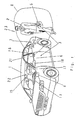
- a motor vehicle 1 with the authorized user 2 can be seen.
- the motor vehicle 1 is provided for access authorization with a locking system 3 as a door closing system, which comprises a first device 4 designed as a control device and an associated second device 5.
- the second device 5 is in the form of an electronic key, an identification (ID) encoder, a smart card, a smart card o. The like. Formed.
- the second device 5 is in the possession of the authorized user 2, whereby it has access to the motor vehicle 1 within an effective range 8.
- the first device 4 has at least two states, in the first state a lock and in the second state an unlocking of the car doors 6 is present.
- the two devices 4, 5 have for their intended operation means for Transmission and / or reception of signals 7 in the manner of transponders by means of a particularly low-frequency electromagnetic carrier wave.
- At least one of these signals 7 transmitted between the second device 5 and the first device 4 is an encoded electromagnetic operating signal 14 (see FIG. 2).
- the coded operating signal 14 is used to authenticate the second device 5, which in justified second device 5 after positive evaluation of the transmitted operating signal 14, a change in the state of the first device 4 is effected.
- the transmission of the coded operating signal 14 takes place when the authorized user 2 actuates the door handle 16 on the car door 6 or approaches the door handle 16.
- the unlocking of the car doors 6 is triggered according to the KeylessEntry functionality.
- the transmission of the coded operating signal 14 can also be done automatically without the involvement of the user 2, as soon as it enters the effective range 8, which is not considered in detail below. If the user 2 closes the car doors 6 from the outside, an automatic locking of the car doors 6 takes place. Equally, the automatic locking of the car doors 6 can take place after the user 2 has left the effective area 8.
- the locking system 3 furthermore determines the driving authorization for the motor vehicle 1.
- the first device 4 designed as a control device also causes the unlocking and / or locking of the ignition lock or the steering wheel lock in accordance with the two states.
- another functionally relevant component of the motor vehicle 1 can be controlled by the first device 4 accordingly. For example, this can be done by a release and / or blocking an immobilizer, the engine control unit o.
- the transmission of the coded operating signal 14 for the authentication of the second device 5 takes place when the authorized user 2 is in the motor vehicle 1 and actuates an electrical switch in the manner of a start / stop switch 11. As a result, the starting process o.
- the motor vehicle 1 corresponding to the intended operation of the means for transmitting and / or receiving signals 7 for the KeylessGo functionality triggered.
- the first device 4 sends by means of a Transmitter / receiver 9 as a means for transmitting and / or receiving signals as a wake-up signal designated first electromagnetic signal 12 for the associated second device 5, which has a corresponding transmitter / receiver 10 as means for transmitting and / or receiving signals.
- the second device 5 is converted from a rest state with reduced energy requirement into an activated state for the intended operation.
- the third electromagnetic signal is transmitted as coded electromagnetic operating signal 14 for authentication by means of the transceivers 9, 10 between the first and the second device 4, 5.
- the signal 14 may in particular consist of a plurality of sub-signals and be transmitted in a bidirectional communication between the two devices 4, 5. With regard to further details of the bidirectional communication itself is also on the DE 43 40 260 A1 directed.
- the wake-up signal 12 may contain, for example, an identifier for the motor vehicle type. After receiving the wake-up signal 12, all the second devices 5 located in the effective region 8 and belonging to the same type of motor vehicle are activated.
- the first device 4 sends between the first signal 12 and the third signal 14 a second electromagnetic signal 13 to the second device 5 as a selection signal, as can be seen in more detail with reference to FIG.
- the second signal 13 contains information about the closer identity of the motor vehicle 1. This causes only the actually belonging to the first device 4 second means 5 remain in the activated state. However, in the activated state, not belonging to the motor vehicle 1 second devices are returned to the idle state.
- a motor vehicle 1 has two lines, namely a first electronic key and spare key as a first line and a second electronic key and spare key as a second line.
- the lines have a ranking for carrying out the authentication, so that if both lines are present in the effective area 8, only an authentication with the higher-ranking line, which is selected accordingly, is to be carried out.
- the Selection signal 13 can now additionally contain information about the lines assigned to first device 4 in order to allow the locking system 3 optionally a selection for the authentication.
- the transponder for the transmitter / receiver 9, 10 has an increased range, in such a way that the intended operation of the two devices 4, 5 is made possible when the two devices 4, 5 are sufficiently close to each other.
- the range of the transponder is designed so that the second device 5 must be located approximately in the position and / or in the immediate vicinity of the position in which the respective effected by the locking system 3 function of the motor vehicle 1 by the user 2 can be operated , In other words, for the KeylessGo function, the range extends close to the driver's seat 15 and the keyless entry functionality in the vicinity of the car doors 6, as can be seen from Fig. 1, so that the user 2 the second device 5 must wear only on the body or close to the body.
- transponder coils 17,18 for the transmitter / receiver 9 are connected via lines 20 to the first device 4 for their intended operation in connection.
- the transponder coil 19 is integrated in the second device 5.
- the transponder coil 17 serving to identify the second device 5 and its position check is expediently arranged in the driver's seat 16 for the KeylessGo functionality.
- the transponder coil 18 for the KeylessEntry functionality is arranged in the frame for the side window 21 on the car door 6 of the motor vehicle 1.
- antennas may also be used. Then, operation of the transceivers 9, 10 is enabled not only with low frequency electromagnetic carrier waves but also with higher frequencies. This can bring advantages for the transmission speed between the two devices 4, 5.
- the invention is not limited to the described and illustrated embodiment.
- the invention furthermore also includes all expert developments within the scope of the patent claims.
- a locking system can be used not only in the vehicle. It is also a use for another door lock, which is for example on a Immobilic o. The like, is possible.
Abstract
Description
Die Erfindung betrifft ein Schließsystem nach dem Oberbegriff des Patentanspruchs 1.The invention relates to a locking system according to the preamble of patent claim 1.
Bei erhöhten Sicherheitsanforderungen werden elektronische Schließsysteme verwendet, die beispielsweise mittels elektromagnetischer Wellen arbeiten. Insbesondere bei Kraftfahrzeugen werden solche Schließsysteme als Türschließsysteme für die Zugangsberechtigung und/oder als Zündschloßsysteme, Lenkradverriegelungen, Wegfahrsperren o. dgl. für die Fahrberechtigung verwendet.Increased security requirements electronic locking systems are used, for example, work by means of electromagnetic waves. In particular, in motor vehicles such locking systems are used as door locking systems for the access authorization and / or as ignition lock systems, steering wheel locks, immobilizers o. The like. For driving authorization.
Derartige Schließsysteme sind aus der
Solche Schließsysteme sind auch mit sogenannten "Keyless"-Funktionalitäten weiterentwickelt. So ist bei der "KeylessEntry"-Funktionalität eine manuelle Betätigung des elektronischen Schlüssels durch den Benutzer nicht mehr notwendig. Es genügt, daß der Benutzer den Schlüssel mit sich führt. Das Betriebssignal wird dann für die Zugangsberechtigung zwischen den beiden Einrichtungen selbsttätig übertragen, wenn der Benutzer sich in einem, in der Nähe des Kraftfahrzeugs befindlichen Wirkbereich aufhält und dort beispielsweise den Türgriff an der Autotüre betätigt Ebenso können diese Schließsysteme eine "KeylessGo"-Funktionalität aufweisen, wobei das Betriebssignal für die Fahrberechtigung zwischen den beiden Einrichtungen selbsttätig übertragen wird, wenn der Benutzer sich innerhalb des Kraftfahrzeugs befindet und beispielsweise eine Start/Stop-Taste im Armaturenbrett betätigt. Für die Keyless-Funktionalitäten können die beiden Einrichtungen zu deren bestimmungsgemäßen Betrieb Sender und/oder Empfänger in der Art von Transpondern für niederfrequente elektromagnetische Signale besitzen.Such locking systems are also developed with so-called "keyless" functionalities. Thus, with the "KeylessEntry" functionality, a manual actuation of the electronic key by the user is no longer necessary. It is enough that the User carries the key. The operating signal is then transmitted automatically for the access authorization between the two devices when the user is in an area of action close to the motor vehicle and there, for example, actuates the door handle on the car door. Likewise, these locking systems can have a "KeylessGo" functionality. wherein the operating signal for the driving authorization between the two devices is automatically transmitted when the user is inside the motor vehicle and, for example, actuates a start / stop button in the dashboard. For the keyless functionalities, the two devices can have transmitters and / or receivers in the form of transponders for low-frequency electromagnetic signals for their intended operation.
Ein KeylessGo- oder auch PassivGo-System heute bekannter Bauweise verfügt im allgemeinen über zwei Möglichkeiten zur Feststellung der Fahrberechtigung. Zum einen kann für die zweite Einrichtung das Wecken und Abgrenzen entsprechend einer Positionsbestimmung der zweiten Einrichtung über niederfrequenete (LF-)Felder und die Kommunikation über hochfrequente (HF-)Felder oder auch aus einer Kombination von HFsowie LF-Feldern erfolgen. Zum anderen kann eine sogenannte "Notfahrfunktion" über LF-Felder oder auch Infrarot(IR)-Felder im Zündschloß erfolgen, um bei leerer Schlüsselbatterie noch mit dem Kraftfahrzeug fahren zu können. Es handelt sich somit um zwei unabhängig voneinander arbeitende Transpondersysteme, wodurch das Schließsystem aufwendig und teuer ist.A keyless Go or Passive Go system of today known construction generally has two options for determining the driving authorization. On the one hand, for the second device, the waking and delimiting can take place according to a position determination of the second device via low-frequency (LF) fields and communication via high-frequency (HF) fields or else from a combination of HF and LF fields. On the other hand, a so-called "emergency driving" via LF fields or infrared (IR) fields done in the ignition to drive when the key battery is still with the car. These are thus two independently operating transponder systems, whereby the locking system is complicated and expensive.
Der Erfindung liegt die Aufgabe zugrunde, das mit "Keyless"-Funkfionalität ausgestattete Schließsystem einfacher und/oder kostengünstiger auszugestalten.The invention has for its object to design the equipped with "Keyless" -Funkfionalität locking system simpler and / or cheaper.
Diese Aufgabe wird bei einem gattungsgemäßen Schließsystem durch die kennzeichnenden Merkmale des Anspruchs 1 gelöst.This object is achieved in a generic locking system by the characterizing features of claim 1.
Beim erfindungsgemäßen Schließsystem besitzt der Transponder eine erhöhte Reichweite. Dadurch ist der bestimmungsgemäße Betrieb der beiden Einrichtungen ermöglicht, wenn die zweite Einrichtung in etwa in der Position und/oder in der Nähe der Position befindlich ist, in der die jeweilige, vom Schließsystem bewirkbare Funktion des Kraftfahrzeugs durch den Benutzer bedienbar ist. Vorteilhafterweise ist durch dieses Funktionsprinzip ein einfaches und kostengünstiges KeylessGo/Entry-System geschaffen. Weitere Ausgestaltungen der Erfindung sind Gegenstand der Unteransprüche.In the locking system according to the invention, the transponder has an increased range. Thereby, the intended operation of the two devices is made possible when the second device is located approximately in the position and / or in the vicinity of the position in which the respective function of the motor vehicle which can be effected by the locking system User is operable. Advantageously, a simple and inexpensive keyless go / entry system is created by this principle of operation. Further embodiments of the invention are the subject of the dependent claims.
Eine Möglichkeit der Vereinfachung ist durch Erhöhung der Reichweite des Transponders für die bisherige "Notfahrfunktion" gegeben. Dies kann beispielweise durch einen speziellen Transponder-Schaltkreis erfolgen. Somit ist das bisherige elektronische Zündschloß mit zusätzlichem Keyless-Steuergerät, das das zweite Transponder-System enthält, überflüssig. Es reicht dann aus, wenn im Kraftfahrzeug ein elektrischer Schalter, insbesondere in der Art eines Start/Stop-Tasters angeordnet ist, derart daß die Bedienung des elektrischen Schalters durch den Benutzer den bestimmungsgemäßen Betrieb der Sender und/oder Empfänger für die KeylessGo-Funktionalität auslöst.One possibility of simplification is given by increasing the range of the transponder for the previous "emergency drive". This can be done for example by a special transponder circuit. Thus, the previous electronic ignition with additional Keyless controller, which contains the second transponder system, superfluous. It is sufficient if in the motor vehicle, an electrical switch, in particular in the manner of a start / stop button is arranged such that the operation of the electrical switch by the user initiates the intended operation of the transmitter and / or receiver for KeylessGo functionality ,
Die Transponderspulen bei niederfrequenten Signalen und/oder die Antennen bei höhcr&cqucnten Signalen für die KeylessGo-Funkfionälität können im Fahrersitz integriert sein. In einfacher Weise kann dann die Identifikation des Schlüssels sowie dessen Positionsüberprüfung erfolgen. Der Schlüssel wird in unmittelbarer Nähe zur Transponderspule erkannt, so daß der Fahrer den Schlüssel am Körper oder in Körpernähe, d.h. in der Nähe zu den im Fahrersitz befindlichen Spulen und/oder Antennen, tragen kann.The transponder coils for low-frequency signals and / or the antennas for higher-quality signals for the KeylessGo radio functionality can be integrated in the driver's seat. In a simple way then the identification of the key and its position verification can be done. The key is recognized in close proximity to the transponder coil so that the driver can hold the key to the body or body, i. near the coils and / or antennas in the driver's seat.
Desweiteren ist eine Erweiterung auf ein einfaches KeylessEntry-System möglich, indem die Transponderspulen und/oder Antennen für die KeylessEntry-Funktionalität im Rahmen für die Seitenscheibe des Kraftfahrzeugs angeordnet sind. Somit umgeben die Spulen und/oder Antennen, die zum Öffnen des Fahrzeugs dienen, beispielsweise die Seitenscheibe.Furthermore, an extension to a simple KeylessEntry system is possible by the transponder coils and / or antennas for KeylessEntry functionality are arranged in the frame for the side window of the motor vehicle. Thus, the coils and / or antennas that serve to open the vehicle, for example, surround the side window.
In einfacher Art und Weise genügt es, wenn die Transponderspulen und/oder Antennen mit der ersten Einrichtung für deren bestimmungsgemäßen Betrieb in Verbindung stehen.In a simple manner, it is sufficient if the transponder coils and / or antennas are connected to the first device for their intended operation.
Die mit der Erfindung erzielten Vorteile bestehen insbesondere darin, daß mit lediglich einem statt wie bisher mit zwei Transpondern ein vereinfachtes KeylessGo/Entry-System realisiert ist. Insbesondere ist die Notfahrfunktion im Keyless-System enthalten. Umgekehrt kann mit Hilfe des Notfahr-Transponders gleichzeitig ein einfaches KeylessGo/Entry-System verwirklicht werden. Es wird dabei lediglich ein Transponder-System benötigt.The advantages achieved by the invention are, in particular, that a simplified keyless entry / entry system is realized with only one instead of the previous two transponders. In particular, the emergency drive function is included in the keyless system. Vice versa can be realized with the help of the emergency transponder at the same time a simple KeylessGo / entry system. Only one transponder system is needed.
Die zweite Einrichtung, beispielsweise der elektronische Schlüssel, benötigt keine Batterie für dessen Betrieb, allenfalls für eine eventuell zusätzliche Funkfernbedienung. Desweiteren können die bisherigen Keyless-Steuergeräte zur Erzeugung der Weck- und/oder Abgrenzungsfelder eingespart werden. Die Transponder-Basisstation kann in einem verdeckten Steuergerät verbaut werden. Im sichtbaren Bereich wird dann nur noch ein Start/Stop-Taster o. dgl. benötigt. Insgesamt ist somit ein einfaches sowie betriebssicheres Schließsystem realisiert, das trotz dieser Verbesserungen kostengünstig herzustellen ist.The second device, such as the electronic key, does not require a battery for its operation, possibly for any additional radio remote control. Furthermore, the previous keyless control units for generating the wake-up and / or demarcation fields can be saved. The transponder base station can be installed in a concealed control unit. In the visible range, only a start / stop button or the like is required. Overall, a simple and reliable locking system is thus realized, which is inexpensive to manufacture despite these improvements.
Ein Ausführungsbeispiel der Erfindung mit verschiedenen Weiterbildungen und Ausgestaltungen ist in den Zeichnungen dargestellt und wird im folgenden näher beschrieben. Es zeigen.
- Fig. 1 ein mit einem Schließsystem ausgestattetes Kraftfahrzeug und
- Fig. 2 ein schematisches Blockschaltbild des Schließsystems mit einem Diagramm zur Übertragung der Signale.
- Fig. 1 is equipped with a locking system motor vehicle and
- Fig. 2 is a schematic block diagram of the locking system with a diagram for transmitting the signals.
In Fig. 1 ist ein Kraftfahrzeug 1 mit dem berechtigten Benutzer 2 zu sehen. Das Kraftfahrzeug 1 ist für die Zugangsberechtigung mit einem Schließsystem 3 als Türschließsystem versehen, das eine als eine Steuereinrichtung ausgebildete erste Einrichtung 4 und eine zugehörige zweite Einrichtung 5 umfaßt. Die zweite Einrichtung 5 ist in der Art eines elektronischen Schlüssels, eines Identifikations(ID)-Gebers, einer Chipkarte, einer Smartcard o. dgl. ausgebildet. Die zweite Einrichtung 5 befindet sich im Besitz des berechtigten Benutzers 2, womit dieser innerhalb eines Wirkbereichs 8 Zugang zum Kraftfahrzeug 1 besitzt.In Fig. 1, a motor vehicle 1 with the authorized
Die erste Einrichtung 4 besitzt wenigstens zwei Zustände, wobei im ersten Zustand eine Verriegelung und im zweiten Zustand eine Entriegelung der Autotüren 6 vorliegt. Die beiden Einrichtungen 4, 5 besitzen zu deren bestimmungsgemäßen Betrieb Mittel zum Senden und/oder Empfangen von Signalen 7 in der Art von Transpondern mittels einer insbesondere niederfrequenten elektromagnetischen Trägerwelle. Bei wenigstens einem dieser zwischen der zweiten Einrichtung 5 und der ersten Einrichtung 4 übertragenen Signale 7 handelt es sich um ein codiertes, elektromagnetisches Betriebssignal 14 (siehe Fig. 2). Das codierte Betriebssignal 14 dient zur Authentikation der zweiten Einrichtung 5, womit bei berechtigter zweiter Einrichtung 5 nach positiver Auswertung des übertragenen Betriebssignals 14 eine Änderung des Zustandes der ersten Einrichtung 4 bewirkbar ist. Die Übertragung des codierten Betriebssignals 14 erfolgt dann, wenn der berechtigte Benutzer 2 den Türgriff 16 an der Autotüre 6 betätigt oder sich dem Türgriff 16 annähert. Dadurch wird die Entriegelung der Autotüren 6 entsprechend der KeylessEntry-Funktionalität ausgelöst. Ebensogut kann die Übertragung des codierten Betriebssignals 14 auch selbsttätig ohne Mitwirkung des Benutzers 2 erfolgen, sobald dieser den Wirkbereich 8 betritt, was jedoch im folgenden nicht näher betrachtet wird. Schließt der Benutzer 2 die Autotüren 6 von außen, so erfolgt eine selbsttätige Verriegelung der Autotüren 6. Ebensogut kann die selbsttätige Verriegelung der Autotüren 6 erfolgen, nachdem der Benutzer 2 den Wirkbereich 8 verlassen hat.The
Das Schließsystem 3 stellt weiterhin die Fahrberechtigung für das Kraftfahrzeug 1 fest. Hierzu bewirkt die als Steuereinrichtung ausgebildete erste Einrichtung 4 ebenfalls entsprechend den beiden Zuständen die Ent- und/oder Verriegelung des Zündschlosses oder der Lenkradverriegelung. Ebensogut kann ein sonstiges funktionsrelevantes Bauteil des Kraftfahrzeugs 1 durch die erste Einrichtung 4 dementsprechend angesteuert werden. Beispielsweise kann dadurch eine Freigabe und/oder Sperrung einer Wegfahrsperre, des Motorsteuergeräts o. dgl. erfolgen. Die Übertragung des codierten Betriebssignals 14 zur Authentikation der zweiten Einrichtung 5 erfolgt dann, wenn der berechtigte Benutzer 2 sich im Kraftfahrzeug 1 befindet und einen elektrischen Schalter in der Art eines Start/Stop-Schalters 11 betätigt. Dadurch wird der Start-Vorgang o. dgl. des Kraftfahrzeugs 1 entsprechend des bestimmungsgemäßen Betriebs der Mittel zum Senden und/oder Empfangen von Signalen 7 für die KeylessGo-Funktionalität ausgelöst.The
Die Funktionsweise des erfindungsgemäßen Schließsystems 3 soll nun anhand der Fig. 2 näher erläutert werden. Zunächst sendet die erste Einrichtung 4 mittels eines Senders/Empfängers 9 als Mittel zum Senden und/oder Empfangen von Signalen ein als Wecksignal bezeichnetes erstes elektromagnetisches Signal 12 für die zugehörige zweite Einrichtung 5, die einen entsprechenden Sender/Empfänger 10 als Mittel zum Senden und/oder Empfangen von Signalen besitzt. Dadurch wird die zweite Einrichtung 5 aus einem Ruhezustand mit verringertem Energiebedarf in einen aktivierten Zustand für den bestimmungsgemäßen Betrieb übergeführt. Nachfolgend wird dann, wie bereits beschrieben, das dritte elektromagnetische Signal als codiertes elektromagnetisches Betriebssignal 14 zur Authentikation mittels der Sender/Empfänger 9, 10 zwischen der ersten und der zweiten Einrichtung 4, 5 übertragen. Das Signal 14 kann insbesondere aus mehreren Teilsignalen bestehen und in einer bidirektionalen Kommunikation zwischen den beiden Einrichtungen 4, 5 übertragen werden. Im Hinblick auf nähere Einzelheiten zur bidirektionalen Kommunikation an sich wird auch auf die
Das Wecksignal 12 kann beispielsweise eine Kennung zum Kraftfahrzeug-Typ enthalten. Nach Empfang des Wecksignals 12 sind zunächst sämtliche im Wirkbereich 8 befindliche zweite Einrichtungen 5, die zum selben Kraftfahrzeug-Typ gehören, aktiviert. In einer weiteren Ausgestaltung des Schließsystems 3 sendet die erste Einrichtung 4 zwischen dem ersten Signal 12 und dem dritten Signal 14 ein zweites elektromagnetisches Signal 13 zur zweiten Einrichtung 5 als Selektionssignal, wie näher anhand von Fig. 2 zu erkennen ist. Das zweite Signal 13 enthält eine Information über die nähere Identität des Kraftfahrzeugs 1. Dadurch wird bewirkt, daß lediglich die tatsächlich zur ersten Einrichtung 4 zugehörigen zweiten Einrichtungen 5 im aktivierten Zustand verbleiben. Im aktivierten Zustand befindliche, nicht zum Kraftfahrzeug 1 zugehörige zweite Einrichtungen werden jedoch in den Ruhezustand zurückgeführt.The wake-
Es bietet sich an, die zur ersten Einrichtung 4 zugehörigen zweiten Einrichtungen 5 in gruppenartige Linien einzuteilen. Bevorzugterweise besitzt ein Kraftfahrzeug 1 zwei Linien, und zwar einen ersten elektronischen Schlüssel sowie Ersatzschlüssel als erste Linie und einen zweiten elektronischen Schlüssel sowie Ersatzschlüssel als zweite Linie. Zweckmäßigerweise weisen die Linien eine Rangfolge zur Durchführung der Authentikation auf, so daß bei Vorhandensein beider Linien im Wirkbereich 8 lediglich eine Authentikation mit der ranghöheren Linie, die entsprechend ausgewählt wird, durchzuführen ist. Das Selektionssignal 13 kann nun zusätzlich eine Information zu den der ersten Einrichtung 4 zugeordneten Linien enthalten, um dem Schließsystem 3 gegebenenfalls eine Auswahl für die Authentikation zu gestatten.It is advisable to divide the
Der Transponder für den Sender/Empfänger 9, 10 besitzt eine erhöhte Reichweite, und zwar derart daß der bestimmungsgemäße Betrieb der beiden Einrichtungen 4, 5 ermöglicht ist, wenn die beiden Einrichtungen 4, 5 genügend nahe beieinander sind. Die Reichweite des Transponders ist dabei so ausgelegt, daß die zweite Einrichtung 5 in etwa in der Position und/oder in der unmittelbaren Nähe der Position befindlich sein muß, in der die jeweilige vom Schließsystem 3 bewirkbare Funktion des Kraftfahrzeugs 1 durch den Benutzer 2 bedienbar ist. Mit anderen Worten erstreckt sich für die KeylessGo-Funktion die Reichweite in die Nähe zum Fahrersitz 15 und für die KeylessEntry-Funktionalität in die Nähe zu den Autotüren 6, wie anhand von Fig. 1 zu erkennen ist, so daß der Benutzer 2 die zweite Einrichtung 5 lediglich am Körper oder in Körpernähe tragen muß. Andererseits kann aufgrund der begrenzten Reichweite des Transponders für die Sender/Empfänger 9, 10 das bisher notwendige Bereichsabgrenzungssignal entfallen, das zur Bestimmung des Standortes der zweiten Einrichtung 5 in Bezug auf die erste Einrichtung 4 dient, also ob die zweite Einrichtung 5 außerhalb am Kraftfahrzeug 1 sowie gegebenenfalls an welcher Stelle des Außenraums 23 und/oder im Innenraum 22 des Kraftfahrzeugs 1 befindlich ist. Dadurch ergibt sich zusätzlich zur Vereinfachung des Schließsystems 3 auch ein Zeitgewinn bei dessen Betrieb,The transponder for the transmitter /
Die in Fig. 2 lediglich schematisch angedeuteten Transponderspulen 17,18 für den Sender/Empfänger 9 stehen über Leitungen 20 mit der ersten Einrichtung 4 für deren bestimmungsgemäßen Betrieb in Verbindung. Hingegen ist in der zweiten Einrichtung 5 die Transponderspule 19 in der zweiten Einrichtung 5 integriert. Wie anhand von Fig. 1 weiterhin zu erkennen ist, ist zweckmäßigerweise die der Identifikation der zweiten Einrichtung 5 sowie deren Positionsüberprüfung dienende Transponderspule17 für die KeylessGo-Funktionalität im Fahrersitz 16 angeordnet. Die Transponderspule 18 für die KeylessEntry-Funktionalität ist im Rahmen für die Seitenscheibe 21 an der Autotüre 6 des Kraftfahrzeugs 1 angeordnet.The only schematically indicated in Fig. 2 transponder coils 17,18 for the transmitter /
Anstelle von Spulen 17, 18, 19, die mit den Transpondern der Sender/Empfänger 9,10 zusammenwirken, können auch Antennen verwendet werden. Dann ist ein Betrieb der Sender/Empfänger 9, 10 nicht nur mit niederfrequenten elektromagnetischen Trägerwellen sondern auch mit höheren Frequenzen ermöglicht. Dies kann Vorteile für die Übertragmgsgeschwindigkeit zwischen den beiden Einrichtungen 4,5 bringen.Instead of
Die Erfindung ist nicht auf das beschriebene und dargestellte Ausführungsbeispiel beschränkt. Die Erfindung umfaßt weiterhin auch alle fachmännischen Weiterbildungen im Rahmen der Schutzrechtsansprüche. So kann ein derartiges Schließsystem nicht nur im Kraftfahrzeug eingesetzt werden. Es ist auch eine Verwendung für ein sonstiges Türschloß, das sich beispielsweise an einer Immobilic o. dgl, befindet, möglich.The invention is not limited to the described and illustrated embodiment. The invention furthermore also includes all expert developments within the scope of the patent claims. Thus, such a locking system can be used not only in the vehicle. It is also a use for another door lock, which is for example on a Immobilic o. The like, is possible.
- 1:1:
- Kraftfahrzeugmotor vehicle
- 2:2:
- (berechtigter) Benutzer(authorized) user
- 3:3:
- Schließsystemlocking system
- 4:4:
- erste Einrichtungfirst device
- 5:5:
- zweite Einrichtungsecond device
- 6:6:
- Autotürecar door
- 7:7:
- Signalsignal
- 8:8th:
- Wirkbereicheffective range
- 9:9:
- Sender/Empfänger (in der ersten Einrichtung)Transmitter / receiver (in the first device)
- 10:10:
- Sender/Empfänger (in der zweiten Einrichtung)Transmitter / receiver (in the second device)
- 11:11:
- Start/Stop-SchalterStart / stop switch
- 12:12:
- (erstes) Signal / Wecksignal(first) signal / wake-up signal
- 13:13:
- (zweites) Signal / Selektionssignal(second) signal / selection signal
- 14:14:
- (drittes) Signal / (codiertes) Betriebssignal(third) signal / (coded) operating signal
- 15:15:
- Fahrersitzdriver's seat
- 16:16:
- Türgriffdoor handle
- 17:17:
- Transponderspule (im Fahrersitz)Transponder coil (in the driver's seat)
- 18:18:
- Transponderspule (an der Seitenscheibe)Transponder coil (on the side window)
- 19:19:
- Transponderspule (in der zweiten Einrichtung)Transponder coil (in the second device)
- 20:20:
- Leitungmanagement
- 21:21:
- Seitenscheibeside window
- 22:22:
- Innenraum (vom Kraftfahrzeug)Interior (from motor vehicle)
- 23:23:
- Außenraum (vom Kraftfahrzeug)Outdoor space (from motor vehicle)
Claims (5)
Applications Claiming Priority (1)
| Application Number | Priority Date | Filing Date | Title |
|---|---|---|---|
| DE102006027727 | 2006-06-16 |
Publications (2)
| Publication Number | Publication Date |
|---|---|
| EP1867535A1 true EP1867535A1 (en) | 2007-12-19 |
| EP1867535B1 EP1867535B1 (en) | 2017-07-19 |
Family
ID=38421723
Family Applications (1)
| Application Number | Title | Priority Date | Filing Date |
|---|---|---|---|
| EP07011521.7A Not-in-force EP1867535B1 (en) | 2006-06-16 | 2007-06-13 | Locking system, in particular for a motor vehicle |
Country Status (1)
| Country | Link |
|---|---|
| EP (1) | EP1867535B1 (en) |
Cited By (4)
| Publication number | Priority date | Publication date | Assignee | Title |
|---|---|---|---|---|
| WO2016156008A1 (en) | 2015-03-31 | 2016-10-06 | Atmel Corporation | System for waking up a battery-operated device |
| DE102015105001A1 (en) | 2015-03-31 | 2016-10-06 | Atmel Corporation | Device for closing and / or opening |
| WO2018073329A1 (en) * | 2016-10-21 | 2018-04-26 | Marquardt Gmbh | Locking system, in particular for a motor vehicle |
| US20220043100A1 (en) * | 2019-04-26 | 2022-02-10 | Denso Corporation | Positioning system |
Families Citing this family (1)
| Publication number | Priority date | Publication date | Assignee | Title |
|---|---|---|---|---|
| EP3594911B1 (en) | 2018-07-11 | 2023-04-19 | Aptiv Technologies Limited | Method for preventing security breaches of a passive remote keyless entry system |
Citations (10)
| Publication number | Priority date | Publication date | Assignee | Title |
|---|---|---|---|---|
| US4688036A (en) | 1983-11-29 | 1987-08-18 | Nissan Motor Company, Limited | Keyless entry system for automotive vehicle with power consumption saving feature |
| DE3820248A1 (en) | 1987-06-16 | 1989-01-05 | Nissan Motor | Keyless actuating system for a vehicle-locking device |
| EP0566970A1 (en) | 1992-04-16 | 1993-10-27 | Leonische Drahtwerke AG | Antenna especially for vehicles |
| DE4340260A1 (en) | 1993-10-01 | 1995-04-06 | Marquardt Gmbh | Locking system, in particular for motor vehicles |
| DE19518410A1 (en) * | 1995-05-19 | 1996-11-21 | Bosch Gmbh Robert | Recognition of car equipment esp. child's seat |
| DE19800638A1 (en) * | 1997-01-09 | 1998-07-16 | Mazda Motor | Airbag system esp for automobile |
| DE19845649A1 (en) * | 1998-10-05 | 2000-04-06 | Kostal Leopold Gmbh & Co Kg | Keyless access/driving authorization controller for motor vehicle has mutually orthogonal antenna coils driven differently so spatial vectorial field superimposition changes continuously |
| DE10325246B3 (en) * | 2003-06-03 | 2004-11-18 | Huf Hülsbeck & Fürst Gmbh & Co. Kg | Electronic vehicle access control system has at least 3 antennas distributed in vehicle, electronic key with 3 mutually orthogonal antennas; controller locates key from received field vector signals |
| EP1504972A1 (en) | 2003-08-08 | 2005-02-09 | Kabushiki Kaisha Tokai Rika Denki Seisakusho | Engine start Controller |
| DE102005017458A1 (en) | 2004-04-24 | 2005-11-10 | Marquardt Gmbh | Operating lock system, especially for motor vehicle, involves comparing field strength of each component of range demarcation signal with first and second thresholds, determining area of location using especially Boolean combinations |
Family Cites Families (1)
| Publication number | Priority date | Publication date | Assignee | Title |
|---|---|---|---|---|
| EP1045947B1 (en) * | 1998-09-14 | 2005-01-26 | Koninklijke Philips Electronics N.V. | Electronic communications system |
-
2007
- 2007-06-13 EP EP07011521.7A patent/EP1867535B1/en not_active Not-in-force
Patent Citations (10)
| Publication number | Priority date | Publication date | Assignee | Title |
|---|---|---|---|---|
| US4688036A (en) | 1983-11-29 | 1987-08-18 | Nissan Motor Company, Limited | Keyless entry system for automotive vehicle with power consumption saving feature |
| DE3820248A1 (en) | 1987-06-16 | 1989-01-05 | Nissan Motor | Keyless actuating system for a vehicle-locking device |
| EP0566970A1 (en) | 1992-04-16 | 1993-10-27 | Leonische Drahtwerke AG | Antenna especially for vehicles |
| DE4340260A1 (en) | 1993-10-01 | 1995-04-06 | Marquardt Gmbh | Locking system, in particular for motor vehicles |
| DE19518410A1 (en) * | 1995-05-19 | 1996-11-21 | Bosch Gmbh Robert | Recognition of car equipment esp. child's seat |
| DE19800638A1 (en) * | 1997-01-09 | 1998-07-16 | Mazda Motor | Airbag system esp for automobile |
| DE19845649A1 (en) * | 1998-10-05 | 2000-04-06 | Kostal Leopold Gmbh & Co Kg | Keyless access/driving authorization controller for motor vehicle has mutually orthogonal antenna coils driven differently so spatial vectorial field superimposition changes continuously |
| DE10325246B3 (en) * | 2003-06-03 | 2004-11-18 | Huf Hülsbeck & Fürst Gmbh & Co. Kg | Electronic vehicle access control system has at least 3 antennas distributed in vehicle, electronic key with 3 mutually orthogonal antennas; controller locates key from received field vector signals |
| EP1504972A1 (en) | 2003-08-08 | 2005-02-09 | Kabushiki Kaisha Tokai Rika Denki Seisakusho | Engine start Controller |
| DE102005017458A1 (en) | 2004-04-24 | 2005-11-10 | Marquardt Gmbh | Operating lock system, especially for motor vehicle, involves comparing field strength of each component of range demarcation signal with first and second thresholds, determining area of location using especially Boolean combinations |
Cited By (9)
| Publication number | Priority date | Publication date | Assignee | Title |
|---|---|---|---|---|
| WO2016156008A1 (en) | 2015-03-31 | 2016-10-06 | Atmel Corporation | System for waking up a battery-operated device |
| DE102015105001A1 (en) | 2015-03-31 | 2016-10-06 | Atmel Corporation | Device for closing and / or opening |
| DE102015105008A1 (en) | 2015-03-31 | 2016-10-06 | Atmel Corporation | Device for activating an electrically or electronically controlled device from an energy-saving passive state |
| CN107995984A (en) * | 2015-03-31 | 2018-05-04 | 微芯片科技公司 | System for the device for waking up battery pack operation |
| US10424141B2 (en) | 2015-03-31 | 2019-09-24 | Marquardt Gmbh | Apparatus for locking and/or unlocking |
| US10452125B2 (en) | 2015-03-31 | 2019-10-22 | Marquardt Gmbh | Apparatus for activating an electrically or electronically controlled appliance from an energy-saving passive state |
| CN107995984B (en) * | 2015-03-31 | 2021-02-26 | 微芯片科技公司 | Device for activating and/or authenticating an electronic or electronic control unit |
| WO2018073329A1 (en) * | 2016-10-21 | 2018-04-26 | Marquardt Gmbh | Locking system, in particular for a motor vehicle |
| US20220043100A1 (en) * | 2019-04-26 | 2022-02-10 | Denso Corporation | Positioning system |
Also Published As
| Publication number | Publication date |
|---|---|
| EP1867535B1 (en) | 2017-07-19 |
Similar Documents
| Publication | Publication Date | Title |
|---|---|---|
| EP2637903B1 (en) | Locking system especially for a vehicle | |
| EP2007610B1 (en) | Electric steering lock, in particular for a motor vehicle | |
| DE102008015477A1 (en) | Closing system, particularly for access or driving authorization for vehicle in style of keyless entry or go function, has device, with two positions, formed as control device | |
| EP1867535B1 (en) | Locking system, in particular for a motor vehicle | |
| DE102013004178A1 (en) | Locking system, in particular for a motor vehicle | |
| EP1191487B1 (en) | Locking system, in particular for a vehicle | |
| EP1619093B1 (en) | Locking system, in particular for a motor vehicle. | |
| EP1595043B1 (en) | Locking system, especially for a motor vehicle | |
| DE10149344B4 (en) | Authorization interrogator for motor vehicles | |
| EP1902913B1 (en) | Locking system, in particular for a motor vehicle | |
| DE102006007961B4 (en) | Keyless entry / go system with control unit and corresponding procedure | |
| EP2825424B1 (en) | Locking system, especially for a motor vehicle | |
| WO2000009835A1 (en) | Access and starting/driving authorization system for a vehicle | |
| DE102014018668A1 (en) | Locking system, in particular for a motor vehicle | |
| DE102007017344A1 (en) | Electric steering lock for use in drive authorization system, has drive for moving locking unit between positions, and electronic system for controlling drive, where electronic system generates signals necessary for drive authorization | |
| DE102005031997A1 (en) | Locking system for motor vehicle has transmitter of first control device allocated to at least two areas of vehicle, and operating component for release of signal from first control device is allocated to each aforesaid area | |
| DE102007042370A1 (en) | Closing system, particularly for access authorization and driving authorization with motor vehicle, has two units and antenna are provided independent of controller by former unit | |
| DE102007027095A1 (en) | Electronic locking system for use as e.g. door locking system, for access and/or drive control in motor vehicle, has control device and associated device e.g. electronic key, exhibiting transponder that exhibits extended range | |
| DE102014009450A1 (en) | Keyless identification transmitter for a motor vehicle | |
| DE10321803B4 (en) | Method for transmitting data and data transmission system operating according to this method | |
| EP1614593B1 (en) | Locking system, in particular for a motor vehicle | |
| DE102011050529A1 (en) | Detection device for provision of e.g. entrance function of motor car, has control unit provided in contact with communication unit, where communication and control units provide accessing and driving authority functions of vehicle | |
| DE102009053985A1 (en) | Locking system, particularly for access or driving authorization in motor vehicle, for example in form of keyless entry or go-functionality, has unit that is formed as control unit and another unit | |
| DE102016014538A1 (en) | Method for operating a keyless entry and drive authorization system | |
| EP3310627B1 (en) | Locking system for a vehicle |
Legal Events
| Date | Code | Title | Description |
|---|---|---|---|
| PUAI | Public reference made under article 153(3) epc to a published international application that has entered the european phase |
Free format text: ORIGINAL CODE: 0009012 |
|
| AK | Designated contracting states |
Kind code of ref document: A1 Designated state(s): AT BE BG CH CY CZ DE DK EE ES FI FR GB GR HU IE IS IT LI LT LU LV MC MT NL PL PT RO SE SI SK TR |
|
| AX | Request for extension of the european patent |
Extension state: AL BA HR MK YU |
|
| 17P | Request for examination filed |
Effective date: 20080328 |
|
| 17Q | First examination report despatched |
Effective date: 20080513 |
|
| AKX | Designation fees paid |
Designated state(s): AT BE BG CH CY CZ DE DK EE ES FI FR GB GR HU IE IS IT LI LT LU LV MC MT NL PL PT RO SE SI SK TR |
|
| GRAP | Despatch of communication of intention to grant a patent |
Free format text: ORIGINAL CODE: EPIDOSNIGR1 |
|
| INTG | Intention to grant announced |
Effective date: 20160706 |
|
| GRAJ | Information related to disapproval of communication of intention to grant by the applicant or resumption of examination proceedings by the epo deleted |
Free format text: ORIGINAL CODE: EPIDOSDIGR1 |
|
| GRAP | Despatch of communication of intention to grant a patent |
Free format text: ORIGINAL CODE: EPIDOSNIGR1 |
|
| GRAJ | Information related to disapproval of communication of intention to grant by the applicant or resumption of examination proceedings by the epo deleted |
Free format text: ORIGINAL CODE: EPIDOSDIGR1 |
|
| INTC | Intention to grant announced (deleted) | ||
| INTG | Intention to grant announced |
Effective date: 20160919 |
|
| GRAJ | Information related to disapproval of communication of intention to grant by the applicant or resumption of examination proceedings by the epo deleted |
Free format text: ORIGINAL CODE: EPIDOSDIGR1 |
|
| GRAP | Despatch of communication of intention to grant a patent |
Free format text: ORIGINAL CODE: EPIDOSNIGR1 |
|
| INTC | Intention to grant announced (deleted) | ||
| GRAP | Despatch of communication of intention to grant a patent |
Free format text: ORIGINAL CODE: EPIDOSNIGR1 |
|
| GRAJ | Information related to disapproval of communication of intention to grant by the applicant or resumption of examination proceedings by the epo deleted |
Free format text: ORIGINAL CODE: EPIDOSDIGR1 |
|
| INTG | Intention to grant announced |
Effective date: 20161122 |
|
| INTC | Intention to grant announced (deleted) | ||
| GRAP | Despatch of communication of intention to grant a patent |
Free format text: ORIGINAL CODE: EPIDOSNIGR1 |
|
| INTG | Intention to grant announced |
Effective date: 20170221 |
|
| GRAS | Grant fee paid |
Free format text: ORIGINAL CODE: EPIDOSNIGR3 |
|
| GRAA | (expected) grant |
Free format text: ORIGINAL CODE: 0009210 |
|
| AK | Designated contracting states |
Kind code of ref document: B1 Designated state(s): AT BE BG CH CY CZ DE DK EE ES FI FR GB GR HU IE IS IT LI LT LU LV MC MT NL PL PT RO SE SI SK TR |
|
| REG | Reference to a national code |
Ref country code: GB Ref legal event code: FG4D Free format text: NOT ENGLISH |
|
| REG | Reference to a national code |
Ref country code: CH Ref legal event code: EP |
|
| REG | Reference to a national code |
Ref country code: IE Ref legal event code: FG4D Free format text: LANGUAGE OF EP DOCUMENT: GERMAN |
|
| REG | Reference to a national code |
Ref country code: AT Ref legal event code: REF Ref document number: 910058 Country of ref document: AT Kind code of ref document: T Effective date: 20170815 |
|
| REG | Reference to a national code |
Ref country code: DE Ref legal event code: R096 Ref document number: 502007015755 Country of ref document: DE |
|
| REG | Reference to a national code |
Ref country code: NL Ref legal event code: MP Effective date: 20170719 |
|
| REG | Reference to a national code |
Ref country code: LT Ref legal event code: MG4D |
|
| PG25 | Lapsed in a contracting state [announced via postgrant information from national office to epo] |
Ref country code: FI Free format text: LAPSE BECAUSE OF FAILURE TO SUBMIT A TRANSLATION OF THE DESCRIPTION OR TO PAY THE FEE WITHIN THE PRESCRIBED TIME-LIMIT Effective date: 20170719 Ref country code: LT Free format text: LAPSE BECAUSE OF FAILURE TO SUBMIT A TRANSLATION OF THE DESCRIPTION OR TO PAY THE FEE WITHIN THE PRESCRIBED TIME-LIMIT Effective date: 20170719 Ref country code: NL Free format text: LAPSE BECAUSE OF FAILURE TO SUBMIT A TRANSLATION OF THE DESCRIPTION OR TO PAY THE FEE WITHIN THE PRESCRIBED TIME-LIMIT Effective date: 20170719 Ref country code: SE Free format text: LAPSE BECAUSE OF FAILURE TO SUBMIT A TRANSLATION OF THE DESCRIPTION OR TO PAY THE FEE WITHIN THE PRESCRIBED TIME-LIMIT Effective date: 20170719 |
|
| PG25 | Lapsed in a contracting state [announced via postgrant information from national office to epo] |
Ref country code: GR Free format text: LAPSE BECAUSE OF FAILURE TO SUBMIT A TRANSLATION OF THE DESCRIPTION OR TO PAY THE FEE WITHIN THE PRESCRIBED TIME-LIMIT Effective date: 20171020 Ref country code: PL Free format text: LAPSE BECAUSE OF FAILURE TO SUBMIT A TRANSLATION OF THE DESCRIPTION OR TO PAY THE FEE WITHIN THE PRESCRIBED TIME-LIMIT Effective date: 20170719 Ref country code: IS Free format text: LAPSE BECAUSE OF FAILURE TO SUBMIT A TRANSLATION OF THE DESCRIPTION OR TO PAY THE FEE WITHIN THE PRESCRIBED TIME-LIMIT Effective date: 20171119 Ref country code: ES Free format text: LAPSE BECAUSE OF FAILURE TO SUBMIT A TRANSLATION OF THE DESCRIPTION OR TO PAY THE FEE WITHIN THE PRESCRIBED TIME-LIMIT Effective date: 20170719 Ref country code: BG Free format text: LAPSE BECAUSE OF FAILURE TO SUBMIT A TRANSLATION OF THE DESCRIPTION OR TO PAY THE FEE WITHIN THE PRESCRIBED TIME-LIMIT Effective date: 20171019 Ref country code: LV Free format text: LAPSE BECAUSE OF FAILURE TO SUBMIT A TRANSLATION OF THE DESCRIPTION OR TO PAY THE FEE WITHIN THE PRESCRIBED TIME-LIMIT Effective date: 20170719 |
|
| REG | Reference to a national code |
Ref country code: DE Ref legal event code: R097 Ref document number: 502007015755 Country of ref document: DE |
|
| PG25 | Lapsed in a contracting state [announced via postgrant information from national office to epo] |
Ref country code: CZ Free format text: LAPSE BECAUSE OF FAILURE TO SUBMIT A TRANSLATION OF THE DESCRIPTION OR TO PAY THE FEE WITHIN THE PRESCRIBED TIME-LIMIT Effective date: 20170719 Ref country code: DK Free format text: LAPSE BECAUSE OF FAILURE TO SUBMIT A TRANSLATION OF THE DESCRIPTION OR TO PAY THE FEE WITHIN THE PRESCRIBED TIME-LIMIT Effective date: 20170719 Ref country code: RO Free format text: LAPSE BECAUSE OF FAILURE TO SUBMIT A TRANSLATION OF THE DESCRIPTION OR TO PAY THE FEE WITHIN THE PRESCRIBED TIME-LIMIT Effective date: 20170719 |
|
| PLBE | No opposition filed within time limit |
Free format text: ORIGINAL CODE: 0009261 |
|
| STAA | Information on the status of an ep patent application or granted ep patent |
Free format text: STATUS: NO OPPOSITION FILED WITHIN TIME LIMIT |
|
| PG25 | Lapsed in a contracting state [announced via postgrant information from national office to epo] |
Ref country code: SK Free format text: LAPSE BECAUSE OF FAILURE TO SUBMIT A TRANSLATION OF THE DESCRIPTION OR TO PAY THE FEE WITHIN THE PRESCRIBED TIME-LIMIT Effective date: 20170719 Ref country code: EE Free format text: LAPSE BECAUSE OF FAILURE TO SUBMIT A TRANSLATION OF THE DESCRIPTION OR TO PAY THE FEE WITHIN THE PRESCRIBED TIME-LIMIT Effective date: 20170719 |
|
| REG | Reference to a national code |
Ref country code: FR Ref legal event code: PLFP Year of fee payment: 12 |
|
| 26N | No opposition filed |
Effective date: 20180420 |
|
| PG25 | Lapsed in a contracting state [announced via postgrant information from national office to epo] |
Ref country code: SI Free format text: LAPSE BECAUSE OF FAILURE TO SUBMIT A TRANSLATION OF THE DESCRIPTION OR TO PAY THE FEE WITHIN THE PRESCRIBED TIME-LIMIT Effective date: 20170719 |
|
| PG25 | Lapsed in a contracting state [announced via postgrant information from national office to epo] |
Ref country code: MT Free format text: LAPSE BECAUSE OF FAILURE TO SUBMIT A TRANSLATION OF THE DESCRIPTION OR TO PAY THE FEE WITHIN THE PRESCRIBED TIME-LIMIT Effective date: 20170719 |
|
| REG | Reference to a national code |
Ref country code: CH Ref legal event code: PL |
|
| REG | Reference to a national code |
Ref country code: BE Ref legal event code: MM Effective date: 20180630 |
|
| REG | Reference to a national code |
Ref country code: IE Ref legal event code: MM4A |
|
| PG25 | Lapsed in a contracting state [announced via postgrant information from national office to epo] |
Ref country code: MC Free format text: LAPSE BECAUSE OF FAILURE TO SUBMIT A TRANSLATION OF THE DESCRIPTION OR TO PAY THE FEE WITHIN THE PRESCRIBED TIME-LIMIT Effective date: 20170719 Ref country code: LU Free format text: LAPSE BECAUSE OF NON-PAYMENT OF DUE FEES Effective date: 20180613 |
|
| PG25 | Lapsed in a contracting state [announced via postgrant information from national office to epo] |
Ref country code: CH Free format text: LAPSE BECAUSE OF NON-PAYMENT OF DUE FEES Effective date: 20180630 Ref country code: IE Free format text: LAPSE BECAUSE OF NON-PAYMENT OF DUE FEES Effective date: 20180613 Ref country code: LI Free format text: LAPSE BECAUSE OF NON-PAYMENT OF DUE FEES Effective date: 20180630 |
|
| PG25 | Lapsed in a contracting state [announced via postgrant information from national office to epo] |
Ref country code: BE Free format text: LAPSE BECAUSE OF NON-PAYMENT OF DUE FEES Effective date: 20180630 |
|
| REG | Reference to a national code |
Ref country code: AT Ref legal event code: MM01 Ref document number: 910058 Country of ref document: AT Kind code of ref document: T Effective date: 20180613 |
|
| PG25 | Lapsed in a contracting state [announced via postgrant information from national office to epo] |
Ref country code: AT Free format text: LAPSE BECAUSE OF NON-PAYMENT OF DUE FEES Effective date: 20180613 |
|
| PG25 | Lapsed in a contracting state [announced via postgrant information from national office to epo] |
Ref country code: TR Free format text: LAPSE BECAUSE OF FAILURE TO SUBMIT A TRANSLATION OF THE DESCRIPTION OR TO PAY THE FEE WITHIN THE PRESCRIBED TIME-LIMIT Effective date: 20170719 |
|
| PG25 | Lapsed in a contracting state [announced via postgrant information from national office to epo] |
Ref country code: PT Free format text: LAPSE BECAUSE OF FAILURE TO SUBMIT A TRANSLATION OF THE DESCRIPTION OR TO PAY THE FEE WITHIN THE PRESCRIBED TIME-LIMIT Effective date: 20170719 Ref country code: HU Free format text: LAPSE BECAUSE OF FAILURE TO SUBMIT A TRANSLATION OF THE DESCRIPTION OR TO PAY THE FEE WITHIN THE PRESCRIBED TIME-LIMIT; INVALID AB INITIO Effective date: 20070613 |
|
| PG25 | Lapsed in a contracting state [announced via postgrant information from national office to epo] |
Ref country code: CY Free format text: LAPSE BECAUSE OF FAILURE TO SUBMIT A TRANSLATION OF THE DESCRIPTION OR TO PAY THE FEE WITHIN THE PRESCRIBED TIME-LIMIT Effective date: 20170719 |
|
| PGFP | Annual fee paid to national office [announced via postgrant information from national office to epo] |
Ref country code: FR Payment date: 20200619 Year of fee payment: 14 |
|
| PGFP | Annual fee paid to national office [announced via postgrant information from national office to epo] |
Ref country code: GB Payment date: 20200625 Year of fee payment: 14 |
|
| REG | Reference to a national code |
Ref country code: DE Ref legal event code: R082 Ref document number: 502007015755 Country of ref document: DE Representative=s name: JOSTARNDT PATENTANWALTS-AG, DE |
|
| PGFP | Annual fee paid to national office [announced via postgrant information from national office to epo] |
Ref country code: DE Payment date: 20200727 Year of fee payment: 14 |
|
| PGFP | Annual fee paid to national office [announced via postgrant information from national office to epo] |
Ref country code: IT Payment date: 20200625 Year of fee payment: 14 |
|
| REG | Reference to a national code |
Ref country code: DE Ref legal event code: R119 Ref document number: 502007015755 Country of ref document: DE |
|
| GBPC | Gb: european patent ceased through non-payment of renewal fee |
Effective date: 20210613 |
|
| PG25 | Lapsed in a contracting state [announced via postgrant information from national office to epo] |
Ref country code: GB Free format text: LAPSE BECAUSE OF NON-PAYMENT OF DUE FEES Effective date: 20210613 Ref country code: DE Free format text: LAPSE BECAUSE OF NON-PAYMENT OF DUE FEES Effective date: 20220101 |
|
| PG25 | Lapsed in a contracting state [announced via postgrant information from national office to epo] |
Ref country code: FR Free format text: LAPSE BECAUSE OF NON-PAYMENT OF DUE FEES Effective date: 20210630 |
|
| PG25 | Lapsed in a contracting state [announced via postgrant information from national office to epo] |
Ref country code: IT Free format text: LAPSE BECAUSE OF NON-PAYMENT OF DUE FEES Effective date: 20210613 |