EP1862728A1 - Lighting and/or signalling device for vehicle with a metallized lens - Google Patents
Lighting and/or signalling device for vehicle with a metallized lens Download PDFInfo
- Publication number
- EP1862728A1 EP1862728A1 EP07301021A EP07301021A EP1862728A1 EP 1862728 A1 EP1862728 A1 EP 1862728A1 EP 07301021 A EP07301021 A EP 07301021A EP 07301021 A EP07301021 A EP 07301021A EP 1862728 A1 EP1862728 A1 EP 1862728A1
- Authority
- EP
- European Patent Office
- Prior art keywords
- lighting
- housing
- light
- signaling
- metallization layer
- Prior art date
- Legal status (The legal status is an assumption and is not a legal conclusion. Google has not performed a legal analysis and makes no representation as to the accuracy of the status listed.)
- Withdrawn
Links
Images


Classifications
-
- F—MECHANICAL ENGINEERING; LIGHTING; HEATING; WEAPONS; BLASTING
- F21—LIGHTING
- F21V—FUNCTIONAL FEATURES OR DETAILS OF LIGHTING DEVICES OR SYSTEMS THEREOF; STRUCTURAL COMBINATIONS OF LIGHTING DEVICES WITH OTHER ARTICLES, NOT OTHERWISE PROVIDED FOR
- F21V3/00—Globes; Bowls; Cover glasses
- F21V3/04—Globes; Bowls; Cover glasses characterised by materials, surface treatments or coatings
-
- F—MECHANICAL ENGINEERING; LIGHTING; HEATING; WEAPONS; BLASTING
- F21—LIGHTING
- F21S—NON-PORTABLE LIGHTING DEVICES; SYSTEMS THEREOF; VEHICLE LIGHTING DEVICES SPECIALLY ADAPTED FOR VEHICLE EXTERIORS
- F21S41/00—Illuminating devices specially adapted for vehicle exteriors, e.g. headlamps
- F21S41/20—Illuminating devices specially adapted for vehicle exteriors, e.g. headlamps characterised by refractors, transparent cover plates, light guides or filters
- F21S41/28—Cover glass
-
- F—MECHANICAL ENGINEERING; LIGHTING; HEATING; WEAPONS; BLASTING
- F21—LIGHTING
- F21S—NON-PORTABLE LIGHTING DEVICES; SYSTEMS THEREOF; VEHICLE LIGHTING DEVICES SPECIALLY ADAPTED FOR VEHICLE EXTERIORS
- F21S43/00—Signalling devices specially adapted for vehicle exteriors, e.g. brake lamps, direction indicator lights or reversing lights
- F21S43/20—Signalling devices specially adapted for vehicle exteriors, e.g. brake lamps, direction indicator lights or reversing lights characterised by refractors, transparent cover plates, light guides or filters
- F21S43/26—Refractors, transparent cover plates, light guides or filters not provided in groups F21S43/235 - F21S43/255
-
- F—MECHANICAL ENGINEERING; LIGHTING; HEATING; WEAPONS; BLASTING
- F21—LIGHTING
- F21S—NON-PORTABLE LIGHTING DEVICES; SYSTEMS THEREOF; VEHICLE LIGHTING DEVICES SPECIALLY ADAPTED FOR VEHICLE EXTERIORS
- F21S43/00—Signalling devices specially adapted for vehicle exteriors, e.g. brake lamps, direction indicator lights or reversing lights
- F21S43/50—Signalling devices specially adapted for vehicle exteriors, e.g. brake lamps, direction indicator lights or reversing lights characterised by aesthetic components not otherwise provided for, e.g. decorative trim, partition walls or covers
Abstract
Description
La présente invention concerne un dispositif d'éclairage et/ou de signalisation à glace métallisée, en particulier un dispositif d'éclairage et/ou de signalisation pour véhicule automobile. Elle concerne le domaine des projecteurs et des feux de véhicule automobile, dans lequel on trouve différents types d'éclairage, parmi lesquels les feux de position, les feux de changement de direction (clignotants), les feux de croisement ou codes, les feux de route, les feux « longue portée » de complément, les feux anti-brouillard, les feux diurnes, etc.The present invention relates to a device for lighting and / or signaling metallized ice, in particular a lighting and / or signaling device for a motor vehicle. It relates to the field of headlamps and motor vehicle lights, in which there are different types of lighting, among which the position lights, the change of direction (flashing) lights, the dipped beam or codes, the lights of road, "long-range" complement lights, fog lights, daytime running lights, etc.
Les dispositifs d'éclairage des véhicules automobiles sont alimentés par le réseau électrique des véhicules et destinés à doter ces derniers d'une source de lumière codifiée. Ils sont classiquement construits par un système optique qui comprend :
- une lampe, qui fait fonction de source lumineuse,
- un réflecteur en forme de parabole, dont la surface est décomposée en facettes calculées et réfléchissantes,
- une surface réfléchissante recouvrant soit un masque, soit le boîtier du dispositif directement, et
- une glace extérieure.
- a lamp, which acts as a light source,
- a parabola-shaped reflector whose surface is decomposed into calculated and reflective facets,
- a reflective surface covering either a mask or the device housing directly, and
- an outside ice cream.
Les projecteurs et feux comportent, de plus en plus, une glace extérieure lisse et totalement translucide, qui permet de voir le réflecteur en parfaite transparence. Cette tendance a pour conséquence de généraliser la métallisation des intérieurs des projecteurs et feux.Headlamps and lights increasingly include a smooth, totally translucent exterior mirror that allows the reflector to be seen in perfect transparency. This trend has the effect of generalizing the metallization of the interior of the headlamps and lights.
Par métallisation, on entend un traitement de surface qui donne un pouvoir réflecteur brillant à un matériau opaque, par dépose d'une fine couche d'un matériau tel que l'aluminium. Ce procédé est couramment appliqué pour la construction des masques de projecteurs. Dans le cas présent, on se propose d'appliquer un procédé de métallisation sur un matériau translucide, tel que le verre ou le PMMA (polyméthacrylate de méthyle), le PC (polycarbonate), un thermoplastique comme l'APEC. En l'appliquant sur la face intérieure d'une glace extérieure du dispositif d'éclairage et/ou de signalisation, on limite la transparence à l'épaisseur du matériau, en conservant notamment sa couleur, et en rendant sa face intérieure réfléchissante.Metallization means a surface treatment which gives a glossy reflectivity to an opaque material, by depositing a thin layer of a material such as aluminum. This process is commonly applied for the construction of headlamp masks. In the present case, it is proposed to apply a metallization process to a translucent material, such as glass or PMMA (polymethyl methacrylate), PC (polycarbonate), a thermoplastic such as APEC. By applying it on the inside of an outer ice of the lighting and / or signaling device, it limits the transparency to the thickness of the material, retaining in particular its color, and making its inner surface reflective.
Mais la métallisation des pièces pose un problème d'aspect : les lignes de recollement matière, de flux matière et les retassures générées par les variations d'épaisseur induites par les fixations et indexages du boîtier sont autant de causes de déformation de la surface métallisée. Par « retassure », on entend une déformation de l'état de surface d'un matériau, due à la contraction du métal lorsqu'il se refroidit, comme cela peut être observé en fin de solidification.But the metallization of the parts poses a problem of aspect: the lines of gluing material, flow material and the sinkings generated by the variations of thickness induced by the fastenings and indexings of the case are as many causes of deformation of the metallized surface. By "shrinkage" is meant a deformation of the surface condition of a material, due to the contraction of the metal as it cools, as can be observed at the end of solidification.
Deux solutions techniques sont couramment utilisées pour remédier à cet inconvénient. Une première solution consiste à utiliser une pièce supplémentaire, le masque, qui vient entre le boîtier du dispositif d'éclairage et/ou de signalisation et la glace extérieure et sur lequel on aura plus facilement supprimé les retassures en n'ayant que petites fixations et indexage à intégrer. Mais la métallisation du masque entraîne la réflexion de la lumière dans certaines zones provoquant des rayons lumineux parasites. Une seconde solution consiste à appliquer des formes de style, telles que godrons, stries, grainage, qui viennent masquer les défauts d'aspect.Two technical solutions are commonly used to overcome this disadvantage. A first solution is to use an additional piece, the mask, which comes between the housing of the lighting and / or signaling device and the outer ice and on which it will be more easily removed the sinkings having only small bindings and indexing to integrate. But the metallization of the mask causes the reflection of light in certain areas causing parasitic light rays. A second solution is to apply style shapes, such as gadroons, streaks, graining, which hide the appearance defects.
Plus particulièrement, on connaît, selon la publication de la demande de brevet
On connaît également, selon la publication de la demande de brevet
Le but de la présente invention est de concevoir un nouveau dispositif d'éclairage et/ou de signalisation à glace métallisée, dans lequel les inconvénients précités sont supprimés grâce à une solution technique nouvelle, plus simple, fiable et économique.The object of the present invention is to design a new lighting and / or signaling system with metallized ice, in which the aforementioned drawbacks are eliminated thanks to a new, simpler, reliable and economical technical solution.
En d'autres termes, la présente invention a pour but de concevoir une nouvelle solution technique, différente en conséquence des solutions retenues dans les dispositifs d'éclairage et/ou de signalisation de l'art antérieur, qui permette notamment de supprimer les problèmes d'aspect mentionnés ci-dessus et les problèmes liés aux rayons lumineux parasites.In other words, the object of the present invention is to design a new technical solution, which is different as a result of the solutions adopted in the lighting and / or signaling devices of the prior art, which makes it possible in particular to eliminate the problems of aspect mentioned above and the problems related to parasitic light rays.
C'est aussi un but de la présente invention de concevoir de nouveaux dispositifs d'éclairage automobiles comprenant moins de pièces, par conséquent plus économiques.It is also an object of the present invention to design new automotive lighting devices with fewer parts, therefore more economical.
Enfin, c'est également un but de la présente invention de concevoir de nouveaux dispositifs d'éclairage automobiles, qui présentent une esthétique perfectionnée avec des effets de lumière, de couleur et de perspective particulièrement appréciés des clients.Finally, it is also an object of the present invention to design new automotive lighting devices, which have an improved aesthetic with effects of light, color and perspective particularly appreciated by customers.
Pour atteindre ces buts, l'invention propose un nouveau dispositif d'éclairage et/ou de signalisation pour véhicule. Il comporte un boîtier avec au moins une cavité comprenant au moins une lampe et au moins un réflecteur, et une glace extérieure, montée sur le boîtier, dont une partie est revêtue sur sa face interne d'une couche de métallisation, ladite partie métallisée de la glace extérieure étant la partie qui n'est pas située en face des lampes, afin de laisser passer la lumière nécessaire aux fonctions d'éclairage et/ou de signalisation.To achieve these aims, the invention proposes a new lighting and / or signaling device for vehicle. It comprises a housing with at least one cavity comprising at least one lamp and at least one reflector, and an outer mirror, mounted on the housing, a part of which is coated on its inner face with a metallization layer, said metallized portion of the outer ice being the part that is not located in front of the lamps, to let through the light necessary for lighting and / or signaling functions.
La partie de la glace extérieure revêtue sur sa face interne d'une couche de métallisation est la partie située près de la jonction avec le boîtier, afin de masquer les défauts d'aspect du boîtier.The part of the outer ice coated on its inner face with a metallization layer is the part located near the junction with the housing, in order to hide the appearance defects of the housing.
Selon un mode préféré de réalisation de l'invention, la partie de la glace extérieure revêtue sur sa face interne d'une couche de métallisation est interrompue sur au moins une zone de la glace extérieure, afin de réaliser un renforcement de la signature visuelle des feux d'éclairage et/ou de signalisation.According to a preferred embodiment of the invention, the portion of the outer ice coated on its inner face with a metallization layer is interrupted on at least one zone of the outer ice, in order to reinforce the visual signature of the lighting and / or signaling lights.
De préférence, ladite zone au moins est une zone en forme de bande étroite.Preferably, said at least one area is a narrow band-shaped area.
De préférence également, ladite zone en forme de bande étroite est située à la périphérie de la glace extérieure, de façon à souligner le contour du dispositif d'éclairage.Also preferably, said narrow band-shaped zone is located at the periphery of the outer ice, so as to emphasize the outline of the lighting device.
Selon un mode de réalisation avantageux de l'invention, ladite zone au moins d'interruption de la couche de métallisation présente une forme ayant un dessin spécifique utilisé pour identifier le véhicule.According to an advantageous embodiment of the invention, said at least one region of interruption of the metallization layer has a shape having a specific design used to identify the vehicle.
On peut également appliquer ce principe sur un écran situé entre le boîtier et la glace extérieure, de façon à permettre de recréer des effets de perspective, très appréciés sur le plan esthétique.It can also be applied on a screen located between the housing and the outer ice, so as to recreate perspective effects, very much appreciated in terms of aesthetics.
D'autres buts, avantages et caractéristiques de l'invention apparaîtront dans la description qui suit d'un mode de réalisation préféré, non limitatif de l'objet et de la portée de la présente demande de brevet, accompagnée de dessins dans lesquels :
- la figure 1 est une représentation en coupe, schématique, d'un projecteur automobile selon une solution technique de l'art antérieur,
- la figure 2 est une représentation en coupe, schématique, d'un projecteur automobile selon la présente invention, et
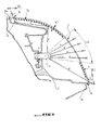
- la figure 3 est une représentation en coupe, schématique, d'une variante de réalisation de la présente invention.
- FIG. 1 is a schematic sectional representation of a motor vehicle headlight according to a technical solution of the prior art,
- FIG. 2 is a diagrammatic sectional representation of a motor vehicle headlamp according to the present invention, and
- Figure 3 is a schematic sectional representation of an alternative embodiment of the present invention.
Sur le dessin de la figure 1, on a représenté, de manière schématique, un projecteur automobile selon une solution technique de l'art antérieur. Le projecteur est de construction classique avec une glace extérieure 1, une ou plusieurs lampes telles que la lampe 3, un réflecteur 2 avec une face intérieure sensiblement parabolique métallisée de façon à réfléchir les rayons lumineux émis par la source 3, un masque 4 de forme générale annulaire et un boîtier 6. La glace 1 est montée sur le boîtier 6, par l'intermédiaire de la nervure de montage périphérique 6a. Le masque 4 est monté entre le boîtier 6 et la glace 1, dans l'espace situé autour des sources lumineuses et de leurs réflecteurs, et il est donc largement ouvert dans sa partie centrale pour laisser passer la lumière émise par la lampe 3 vers la glace extérieure 1 transparente. Le masque 4 est moulé en une seule pièce et, comme les réflecteurs, subit une étape de traitement de surface de type métallisation. Cette étape de métallisation est délicate, dans la mesure où il faut un revêtement homogène d'aspect, bien continu. Plus les pièces à métalliser sont profondes, plus cette homogénéité d'aspect est difficile à obtenir. La métallisation simultanée des masques et des réflecteurs associés est difficile, quand les cavités ainsi créées sont beaucoup plus profondes que hautes.In the drawing of Figure 1, there is shown schematically an automotive projector according to a technical solution of the prior art. The projector is of conventional construction with an outer glass 1, one or more lamps such as the
Il peut y avoir plusieurs cavités adjacentes dans le boîtier du dispositif, chacune d'elles étant équipée d'une ou plusieurs lampes pour remplir plusieurs fonctions. A titre d'exemple, il peut s'agir de deux cavités : une pour l'éclairage et équipée d'une lampe pour feux de route/de croisement et une pour un clignotant. Ces cavités comportent des parois formant réflecteur. Ces parois ont un fond percé d'une ouverture pour permettre d'introduire et éventuellement de fixer la lampe dans les cavités.There may be several adjacent cavities in the device housing, each of which is equipped with one or more lamps to perform several functions. For example, there may be two cavities: one for lighting and equipped with a lamp for high / low beam and one for a flasher. These cavities comprise reflector walls. These walls have a bottom pierced with an opening to allow to introduce and possibly fix the lamp in the cavities.
Sur le dessin de la figure 2, on a représenté, de façon schématique, un exemple de projecteur automobile selon la présente invention. Dans la construction de la figure 2, il n'y a plus de masque 4, et une partie de la face interne de la glace extérieure 1 est revêtue d'une couche de métallisation, d'épaisseur désignée « e », à savoir les portions de face interne 7a et 7b de la glace extérieure 1.In the drawing of Figure 2, there is shown schematically an exemplary automotive headlight according to the present invention. In the construction of FIG. 2, there is no longer a
Les parties métallisées 7a et 7b de la face interne de la glace extérieure 1 sont choisies de façon à ne pas se trouver en face des lampes et fonctions afin de laisser passer la lumière nécessaire aux fonctions d'éclairage et/ou de signalisation. Le secteur référencé A sur le dessin de la figure 2 représente l'espace dans lequel passe la lumière émise par la source lumineuse 3.The
L'application d'une métallisation sur la face interne de la glace extérieure 1 a pour avantage de masquer les défauts d'aspect du boîtier 6, en faisant l'économie d'une pièce supplémentaire comme le masque 4 du mode de réalisation de l'art antérieur illustré sur la figure 1. Les zones métallisées, 7a et 7b, de la glace 1 sont situées dans la partie située près de la jonction 6a de la glace 1 avec le boîtier 6, et cette situation offre l'avantage de masquer les défauts d'aspect du boîtier dans cette partie.The application of a metallization on the inner face of the outer glass 1 has the advantage of masking the appearance defects of the
On a représenté sur le dessin de la figure 3 une variante de réalisation de la présente invention. La glace extérieure 1 est métallisée sur sa face interne en laissant une zone A sans métallisation afin de permettre le passage du flux lumineux provenant de la source lumineuse 3. Ce flux lumineux qui traverse la paroi transparente de la glace extérieure 1 est illustré par tous les rayons lumineux désignés « a ». La métallisation, d'épaisseur « e », porte, comme dans l'exemple précédent de la figure 2, sur des parties 7a et 7b de la glace extérieure 1, situées de part et d'autre de la partie A. Mais dans le mode de réalisation de la figure 3, la métallisation ne s'étend pas jusqu'aux extrémités de la glace extérieure 1 au voisinage de la liaison 6a avec le boîtier 6. La métallisation est « interrompue » sur la périphérie de la glace 1, lesdites interruptions de métallisation étant référencées 7c et 7d, de longueur transversale h1 et h2, respectivement.There is shown in the drawing of Figure 3 an alternative embodiment of the present invention. The outer ice 1 is metallized on its inner face leaving a zone A without metallization to allow the passage of the luminous flux from the
La lampe 3, située derrière la glace 1, envoie de la lumière entre la glace 1 et le boîtier 6. Une partie de cette lumière, représentée sur le dessin de la figure 3 par les rayons lumineux c et d, ressort par la glace transparente en traversant les parties 7c et 7d non métallisées. Le rayon désigné c, en particulier, représente la portion de lumière, émise par la lampe 3, qui est réfléchie par la surface interne métallisée 7a de la glace 1, puis dirigée par cette réflexion contre une paroi interne du boîtier 6 avant de traverser la glace extérieure 1 dans sa partie non métallisée 7c en forme de bande étroite de longueur h1 en section transversale. Le rayon désigné d sur le dessin de la figure 3 illustre la portion de lumière émise par la source lumineuse 3 qui est dirigée directement sur la partie 7d, non métallisée, en périphérie de la glace extérieure 1.The
Les zones non métallisées 7c et 7d permettent de créer une forme spécifique lumineuse identifiant le véhicule soit par un dessin spécifique, soit en soulignant le contour spécifique à ce feu qui est celui de la glace 1 lisse et translucide.The
En variante, une telle création de forme lumineuse par dessin d'une ou plusieurs interruptions de métallisation peut être également appliquée sur un écran situé entre le boîtier 6 et la glace extérieure 1, de manière à créer des effets de perspective.Alternatively, such a luminous shape creation by drawing one or more metallization interrupts can also be applied on a screen located between the
Bien entendu, la présente invention n'est pas limitée aux modes de réalisation décrits et représentés ci-dessus à titre d'exemples ; d'autres modes de réalisation peuvent être conçus par l'homme de métier sans sortir du cadre et de la portée de la présente invention.Of course, the present invention is not limited to the embodiments described and represented above by way of examples; other embodiments may be designed by those skilled in the art without departing from the scope and scope of the present invention.
Claims (8)
Applications Claiming Priority (1)
| Application Number | Priority Date | Filing Date | Title |
|---|---|---|---|
| FR0651927A FR2901597A1 (en) | 2006-05-29 | 2006-05-29 | Lighting/signalling device e.g. headlight, for motor vehicle, has lens including inner face portions covered with metallization layer and located near junction of lens with case, and screen carrying non-metalized parts creating light form |
Publications (1)
| Publication Number | Publication Date |
|---|---|
| EP1862728A1 true EP1862728A1 (en) | 2007-12-05 |
Family
ID=37459794
Family Applications (1)
| Application Number | Title | Priority Date | Filing Date |
|---|---|---|---|
| EP07301021A Withdrawn EP1862728A1 (en) | 2006-05-29 | 2007-05-09 | Lighting and/or signalling device for vehicle with a metallized lens |
Country Status (2)
| Country | Link |
|---|---|
| EP (1) | EP1862728A1 (en) |
| FR (1) | FR2901597A1 (en) |
Cited By (3)
| Publication number | Priority date | Publication date | Assignee | Title |
|---|---|---|---|---|
| FR3022866A1 (en) * | 2014-06-30 | 2016-01-01 | Valeo Vision | LUMINOUS DEVICE FOR MOTOR VEHICLE WITH IMPROVED DIFFUSING ICE |
| FR3062708A1 (en) * | 2017-02-07 | 2018-08-10 | Peugeot Citroen Automobiles Sa | VEHICLE OPTICAL BLOCK WITH INTERNAL SIDE AND VISIBLE FROM OUTSIDE |
| EP3049284B1 (en) * | 2013-09-27 | 2021-03-03 | PSA Automobiles SA | Illumination device having two illumination functions carried out by a single set of light sources and light leaks |
Families Citing this family (1)
| Publication number | Priority date | Publication date | Assignee | Title |
|---|---|---|---|---|
| JP2022064168A (en) * | 2020-10-13 | 2022-04-25 | 株式会社小糸製作所 | Vehicular lamp fitting |
Citations (9)
| Publication number | Priority date | Publication date | Assignee | Title |
|---|---|---|---|---|
| FR2023520A1 (en) * | 1968-11-18 | 1970-08-21 | Lucas Industries Ltd | |
| FR2564945A1 (en) * | 1984-05-25 | 1985-11-29 | Cibie Projecteurs | Improvements to car headlights |
| DE4341825A1 (en) * | 1992-12-18 | 1994-06-23 | Volkswagen Ag | Illuminated sign or badge esp. for body of motor vehicle |
| US5546284A (en) * | 1994-04-19 | 1996-08-13 | Koito Manufacturing Co., Ltd. | Automobile headlamp with extension reflector mounted on the front lense |
| EP1191280A1 (en) * | 2000-09-25 | 2002-03-27 | Valeo Vision | Lighting or signaling device for automotive vehicles with improved appearance |
| FR2840387A1 (en) | 2002-05-31 | 2003-12-05 | Valeo Vision | LIGHTING AND / OR SIGNALING DEVICE FOR VEHICLE COMPRISING A MASK |
| FR2848285A1 (en) | 2002-12-05 | 2004-06-11 | Valeo Vision | METHOD OF PERFORMING AN OPTICAL FUNCTION ON A COMPONENT OF A LIGHTING OR AUTOMOTIVE SIGNALING DEVICE |
| US20050068783A1 (en) * | 2001-11-02 | 2005-03-31 | Ken Egashira | Decorative article and vehicular lamp |
| DE102004023594A1 (en) * | 2004-05-13 | 2005-12-29 | Hella Kgaa Hueck & Co. | Head light for motor vehicles has covering which has circular or semi-circular transparent section which differentiates itself optically from other parts of covering either in its color or in its shining effect |
-
2006
- 2006-05-29 FR FR0651927A patent/FR2901597A1/en not_active Withdrawn
-
2007
- 2007-05-09 EP EP07301021A patent/EP1862728A1/en not_active Withdrawn
Patent Citations (9)
| Publication number | Priority date | Publication date | Assignee | Title |
|---|---|---|---|---|
| FR2023520A1 (en) * | 1968-11-18 | 1970-08-21 | Lucas Industries Ltd | |
| FR2564945A1 (en) * | 1984-05-25 | 1985-11-29 | Cibie Projecteurs | Improvements to car headlights |
| DE4341825A1 (en) * | 1992-12-18 | 1994-06-23 | Volkswagen Ag | Illuminated sign or badge esp. for body of motor vehicle |
| US5546284A (en) * | 1994-04-19 | 1996-08-13 | Koito Manufacturing Co., Ltd. | Automobile headlamp with extension reflector mounted on the front lense |
| EP1191280A1 (en) * | 2000-09-25 | 2002-03-27 | Valeo Vision | Lighting or signaling device for automotive vehicles with improved appearance |
| US20050068783A1 (en) * | 2001-11-02 | 2005-03-31 | Ken Egashira | Decorative article and vehicular lamp |
| FR2840387A1 (en) | 2002-05-31 | 2003-12-05 | Valeo Vision | LIGHTING AND / OR SIGNALING DEVICE FOR VEHICLE COMPRISING A MASK |
| FR2848285A1 (en) | 2002-12-05 | 2004-06-11 | Valeo Vision | METHOD OF PERFORMING AN OPTICAL FUNCTION ON A COMPONENT OF A LIGHTING OR AUTOMOTIVE SIGNALING DEVICE |
| DE102004023594A1 (en) * | 2004-05-13 | 2005-12-29 | Hella Kgaa Hueck & Co. | Head light for motor vehicles has covering which has circular or semi-circular transparent section which differentiates itself optically from other parts of covering either in its color or in its shining effect |
Cited By (4)
| Publication number | Priority date | Publication date | Assignee | Title |
|---|---|---|---|---|
| EP3049284B1 (en) * | 2013-09-27 | 2021-03-03 | PSA Automobiles SA | Illumination device having two illumination functions carried out by a single set of light sources and light leaks |
| FR3022866A1 (en) * | 2014-06-30 | 2016-01-01 | Valeo Vision | LUMINOUS DEVICE FOR MOTOR VEHICLE WITH IMPROVED DIFFUSING ICE |
| EP2963336A3 (en) * | 2014-06-30 | 2016-04-13 | Valeo Vision | Light device for a motor vehicle with improved diffusing lens |
| FR3062708A1 (en) * | 2017-02-07 | 2018-08-10 | Peugeot Citroen Automobiles Sa | VEHICLE OPTICAL BLOCK WITH INTERNAL SIDE AND VISIBLE FROM OUTSIDE |
Also Published As
| Publication number | Publication date |
|---|---|
| FR2901597A1 (en) | 2007-11-30 |
Similar Documents
| Publication | Publication Date | Title |
|---|---|---|
| EP2476947B1 (en) | Lighting or signalling device with an optical guide for an automobile vehicle | |
| EP2598374B1 (en) | Signal lamps for motor vehicle | |
| EP3059120B1 (en) | Lighting device for a motor vehicle | |
| EP3390900B1 (en) | Light module, in particular for vehicle stop light | |
| FR2590351A1 (en) | DUAL-FUNCTION SIGNALING LIGHT FOR VEHICLE | |
| EP1801492A1 (en) | Lighting or signalling device with an optical guide for an automobile | |
| EP3273149A1 (en) | Light module for a motor vehicle | |
| WO2017121944A1 (en) | Optical unit including a signaling light having a flat light guide projecting from the outer lens | |
| EP0632228B1 (en) | Styling or optical element having a shining aspect and a neutral colour- for vehicle headlamps or lamps for signalling | |
| EP1862728A1 (en) | Lighting and/or signalling device for vehicle with a metallized lens | |
| EP1378393B1 (en) | Signalling device and vehicle body part with such a device | |
| WO2016051043A1 (en) | Motor vehicle with radiator grille and signalling light | |
| EP2927050B1 (en) | Luminous device with deflecting shield | |
| FR2661377A1 (en) | Signalling light for motor vehicles | |
| FR2978395A1 (en) | Optical lighting and signaling device e.g. fog light, for e.g. tailgate in low part of electric vehicle windscreen, has LED emitting light rays through part of left transparent portions of light curtain or light curtain/guide subassembly | |
| WO2019043175A1 (en) | Body part having a metallized surface forming a wheel cover and light reflector | |
| EP2175192A1 (en) | Lighting and/or signalling device for an automobile | |
| EP0526337B1 (en) | Geometrically improved signal light assembly, particularly for vehicles | |
| EP4090556B1 (en) | Bodywork element comprising simplified equipment fastening means, and vehicle comprising such a bodywork element | |
| WO2015049444A1 (en) | Lighting device with an open partition for shifting the area of impact of solar beams passing through a lens | |
| FR2903340A1 (en) | Fabricating a mirror of a lighting device and/or of signalization integrated to an element of a car body, comprises bi-injecting a first and a second thermoplastic material to produce the mirror and a hub cap in a co-molded part | |
| FR3018750A1 (en) | PROJECTOR OR FIRE BOX OF A MOTOR VEHICLE OBTAINED BY MOLDING | |
| WO2023209303A1 (en) | Lighting device with dog-legged light guide(s) | |
| FR2963292A1 (en) | Optical device for use in e.g. door of boot to serve as lantern at rear of motor vehicle, has subassembly provided with light curtain, where device emits light rays through transparent part of transparent plates | |
| FR3127548A1 (en) | Vehicle light unit with multiple light guide |
Legal Events
| Date | Code | Title | Description |
|---|---|---|---|
| PUAI | Public reference made under article 153(3) epc to a published international application that has entered the european phase |
Free format text: ORIGINAL CODE: 0009012 |
|
| AK | Designated contracting states |
Kind code of ref document: A1 Designated state(s): AT BE BG CH CY CZ DE DK EE ES FI FR GB GR HU IE IS IT LI LT LU LV MC MT NL PL PT RO SE SI SK TR |
|
| AX | Request for extension of the european patent |
Extension state: AL BA HR MK YU |
|
| 17P | Request for examination filed |
Effective date: 20071214 |
|
| 17Q | First examination report despatched |
Effective date: 20080116 |
|
| AKX | Designation fees paid |
Designated state(s): AT BE BG CH CY CZ DE DK EE ES FI FR GB GR HU IE IS IT LI LT LU LV MC MT NL PL PT RO SE SI SK TR |
|
| GRAP | Despatch of communication of intention to grant a patent |
Free format text: ORIGINAL CODE: EPIDOSNIGR1 |
|
| STAA | Information on the status of an ep patent application or granted ep patent |
Free format text: STATUS: THE APPLICATION IS DEEMED TO BE WITHDRAWN |
|
| 18D | Application deemed to be withdrawn |
Effective date: 20090714 |