EP1861024B1 - Low profile spinal tethering devices - Google Patents
Low profile spinal tethering devices Download PDFInfo
- Publication number
- EP1861024B1 EP1861024B1 EP06719044A EP06719044A EP1861024B1 EP 1861024 B1 EP1861024 B1 EP 1861024B1 EP 06719044 A EP06719044 A EP 06719044A EP 06719044 A EP06719044 A EP 06719044A EP 1861024 B1 EP1861024 B1 EP 1861024B1
- Authority
- EP
- European Patent Office
- Prior art keywords
- staple
- tether
- spinal
- staple body
- bone
- Prior art date
- Legal status (The legal status is an assumption and is not a legal conclusion. Google has not performed a legal analysis and makes no representation as to the accuracy of the status listed.)
- Active
Links
- 238000004873 anchoring Methods 0.000 claims abstract description 87
- 210000000988 bone and bone Anatomy 0.000 claims abstract description 71
- 230000037361 pathway Effects 0.000 claims description 40
- 230000013011 mating Effects 0.000 claims description 22
- 230000000295 complement effect Effects 0.000 claims description 10
- 238000000034 method Methods 0.000 abstract description 18
- 206010058907 Spinal deformity Diseases 0.000 abstract description 7
- 230000008878 coupling Effects 0.000 abstract description 2
- 238000010168 coupling process Methods 0.000 abstract description 2
- 238000005859 coupling reaction Methods 0.000 abstract description 2
- 239000000463 material Substances 0.000 description 10
- 230000012010 growth Effects 0.000 description 9
- 239000007943 implant Substances 0.000 description 8
- -1 poly(ethylene terephthalate) Polymers 0.000 description 7
- 230000004927 fusion Effects 0.000 description 4
- 229920000139 polyethylene terephthalate Polymers 0.000 description 4
- 239000005020 polyethylene terephthalate Substances 0.000 description 4
- 229920000785 ultra high molecular weight polyethylene Polymers 0.000 description 4
- 239000004699 Ultra-high molecular weight polyethylene Substances 0.000 description 3
- 239000000835 fiber Substances 0.000 description 3
- 206010023509 Kyphosis Diseases 0.000 description 2
- 230000000712 assembly Effects 0.000 description 2
- 238000000429 assembly Methods 0.000 description 2
- 239000002537 cosmetic Substances 0.000 description 2
- 230000003116 impacting effect Effects 0.000 description 2
- 238000004519 manufacturing process Methods 0.000 description 2
- OKTJSMMVPCPJKN-UHFFFAOYSA-N Carbon Chemical compound [C] OKTJSMMVPCPJKN-UHFFFAOYSA-N 0.000 description 1
- 102000008186 Collagen Human genes 0.000 description 1
- 108010035532 Collagen Proteins 0.000 description 1
- 229920000271 Kevlar® Polymers 0.000 description 1
- 208000007623 Lordosis Diseases 0.000 description 1
- 239000004677 Nylon Substances 0.000 description 1
- 241000906034 Orthops Species 0.000 description 1
- 208000031481 Pathologic Constriction Diseases 0.000 description 1
- 208000000875 Spinal Curvatures Diseases 0.000 description 1
- 208000007103 Spondylolisthesis Diseases 0.000 description 1
- 229920010741 Ultra High Molecular Weight Polyethylene (UHMWPE) Polymers 0.000 description 1
- 230000002159 abnormal effect Effects 0.000 description 1
- 238000002048 anodisation reaction Methods 0.000 description 1
- 238000005452 bending Methods 0.000 description 1
- 230000008468 bone growth Effects 0.000 description 1
- 238000009954 braiding Methods 0.000 description 1
- 239000001506 calcium phosphate Substances 0.000 description 1
- 229910000389 calcium phosphate Inorganic materials 0.000 description 1
- 235000011010 calcium phosphates Nutrition 0.000 description 1
- 229910052799 carbon Inorganic materials 0.000 description 1
- 239000011248 coating agent Substances 0.000 description 1
- 238000000576 coating method Methods 0.000 description 1
- 229920001436 collagen Polymers 0.000 description 1
- 238000005520 cutting process Methods 0.000 description 1
- 230000000991 decompressive effect Effects 0.000 description 1
- 230000000593 degrading effect Effects 0.000 description 1
- 208000037265 diseases, disorders, signs and symptoms Diseases 0.000 description 1
- 238000006073 displacement reaction Methods 0.000 description 1
- 230000000694 effects Effects 0.000 description 1
- 239000003102 growth factor Substances 0.000 description 1
- 238000002513 implantation Methods 0.000 description 1
- 238000003780 insertion Methods 0.000 description 1
- 230000037431 insertion Effects 0.000 description 1
- 238000002324 minimally invasive surgery Methods 0.000 description 1
- 238000012978 minimally invasive surgical procedure Methods 0.000 description 1
- 229920001778 nylon Polymers 0.000 description 1
- 229920000642 polymer Polymers 0.000 description 1
- 238000002360 preparation method Methods 0.000 description 1
- 230000001737 promoting effect Effects 0.000 description 1
- 206010039722 scoliosis Diseases 0.000 description 1
- 238000001228 spectrum Methods 0.000 description 1
- 230000036262 stenosis Effects 0.000 description 1
- 208000037804 stenosis Diseases 0.000 description 1
- 238000001356 surgical procedure Methods 0.000 description 1
- QORWJWZARLRLPR-UHFFFAOYSA-H tricalcium bis(phosphate) Chemical compound [Ca+2].[Ca+2].[Ca+2].[O-]P([O-])([O-])=O.[O-]P([O-])([O-])=O QORWJWZARLRLPR-UHFFFAOYSA-H 0.000 description 1
- 238000009941 weaving Methods 0.000 description 1
Images


Classifications
-
- A—HUMAN NECESSITIES
- A61—MEDICAL OR VETERINARY SCIENCE; HYGIENE
- A61B—DIAGNOSIS; SURGERY; IDENTIFICATION
- A61B17/00—Surgical instruments, devices or methods, e.g. tourniquets
- A61B17/56—Surgical instruments or methods for treatment of bones or joints; Devices specially adapted therefor
- A61B17/58—Surgical instruments or methods for treatment of bones or joints; Devices specially adapted therefor for osteosynthesis, e.g. bone plates, screws, setting implements or the like
- A61B17/68—Internal fixation devices, including fasteners and spinal fixators, even if a part thereof projects from the skin
- A61B17/70—Spinal positioners or stabilisers ; Bone stabilisers comprising fluid filler in an implant
- A61B17/7053—Spinal positioners or stabilisers ; Bone stabilisers comprising fluid filler in an implant with parts attached to bones or to each other by flexible wires, straps, sutures or cables
-
- A—HUMAN NECESSITIES
- A61—MEDICAL OR VETERINARY SCIENCE; HYGIENE
- A61B—DIAGNOSIS; SURGERY; IDENTIFICATION
- A61B17/00—Surgical instruments, devices or methods, e.g. tourniquets
- A61B17/064—Surgical staples, i.e. penetrating the tissue
- A61B17/0642—Surgical staples, i.e. penetrating the tissue for bones, e.g. for osteosynthesis or connecting tendon to bone
-
- A—HUMAN NECESSITIES
- A61—MEDICAL OR VETERINARY SCIENCE; HYGIENE
- A61B—DIAGNOSIS; SURGERY; IDENTIFICATION
- A61B17/00—Surgical instruments, devices or methods, e.g. tourniquets
- A61B17/16—Bone cutting, breaking or removal means other than saws, e.g. Osteoclasts; Drills or chisels for bones; Trepans
- A61B17/1662—Bone cutting, breaking or removal means other than saws, e.g. Osteoclasts; Drills or chisels for bones; Trepans for particular parts of the body
- A61B17/1671—Bone cutting, breaking or removal means other than saws, e.g. Osteoclasts; Drills or chisels for bones; Trepans for particular parts of the body for the spine
-
- A—HUMAN NECESSITIES
- A61—MEDICAL OR VETERINARY SCIENCE; HYGIENE
- A61B—DIAGNOSIS; SURGERY; IDENTIFICATION
- A61B17/00—Surgical instruments, devices or methods, e.g. tourniquets
- A61B17/56—Surgical instruments or methods for treatment of bones or joints; Devices specially adapted therefor
- A61B17/58—Surgical instruments or methods for treatment of bones or joints; Devices specially adapted therefor for osteosynthesis, e.g. bone plates, screws, setting implements or the like
- A61B17/68—Internal fixation devices, including fasteners and spinal fixators, even if a part thereof projects from the skin
- A61B17/70—Spinal positioners or stabilisers ; Bone stabilisers comprising fluid filler in an implant
- A61B17/7001—Screws or hooks combined with longitudinal elements which do not contact vertebrae
- A61B17/7002—Longitudinal elements, e.g. rods
- A61B17/701—Longitudinal elements with a non-circular, e.g. rectangular, cross-section
-
- A—HUMAN NECESSITIES
- A61—MEDICAL OR VETERINARY SCIENCE; HYGIENE
- A61B—DIAGNOSIS; SURGERY; IDENTIFICATION
- A61B17/00—Surgical instruments, devices or methods, e.g. tourniquets
- A61B17/56—Surgical instruments or methods for treatment of bones or joints; Devices specially adapted therefor
- A61B17/58—Surgical instruments or methods for treatment of bones or joints; Devices specially adapted therefor for osteosynthesis, e.g. bone plates, screws, setting implements or the like
- A61B17/68—Internal fixation devices, including fasteners and spinal fixators, even if a part thereof projects from the skin
- A61B17/70—Spinal positioners or stabilisers ; Bone stabilisers comprising fluid filler in an implant
- A61B17/7001—Screws or hooks combined with longitudinal elements which do not contact vertebrae
- A61B17/7002—Longitudinal elements, e.g. rods
- A61B17/7019—Longitudinal elements having flexible parts, or parts connected together, such that after implantation the elements can move relative to each other
- A61B17/7022—Tethers, i.e. longitudinal elements capable of transmitting tension only, e.g. straps, sutures or cables
-
- A—HUMAN NECESSITIES
- A61—MEDICAL OR VETERINARY SCIENCE; HYGIENE
- A61B—DIAGNOSIS; SURGERY; IDENTIFICATION
- A61B17/00—Surgical instruments, devices or methods, e.g. tourniquets
- A61B17/56—Surgical instruments or methods for treatment of bones or joints; Devices specially adapted therefor
- A61B17/58—Surgical instruments or methods for treatment of bones or joints; Devices specially adapted therefor for osteosynthesis, e.g. bone plates, screws, setting implements or the like
- A61B17/68—Internal fixation devices, including fasteners and spinal fixators, even if a part thereof projects from the skin
- A61B17/70—Spinal positioners or stabilisers ; Bone stabilisers comprising fluid filler in an implant
- A61B17/7001—Screws or hooks combined with longitudinal elements which do not contact vertebrae
- A61B17/7035—Screws or hooks, wherein a rod-clamping part and a bone-anchoring part can pivot relative to each other
- A61B17/704—Screws or hooks, wherein a rod-clamping part and a bone-anchoring part can pivot relative to each other the longitudinal element passing through a ball-joint in the screw head
-
- A—HUMAN NECESSITIES
- A61—MEDICAL OR VETERINARY SCIENCE; HYGIENE
- A61B—DIAGNOSIS; SURGERY; IDENTIFICATION
- A61B17/00—Surgical instruments, devices or methods, e.g. tourniquets
- A61B17/56—Surgical instruments or methods for treatment of bones or joints; Devices specially adapted therefor
- A61B17/58—Surgical instruments or methods for treatment of bones or joints; Devices specially adapted therefor for osteosynthesis, e.g. bone plates, screws, setting implements or the like
- A61B17/68—Internal fixation devices, including fasteners and spinal fixators, even if a part thereof projects from the skin
- A61B17/84—Fasteners therefor or fasteners being internal fixation devices
- A61B17/86—Pins or screws or threaded wires; nuts therefor
- A61B17/8695—Washers
-
- A—HUMAN NECESSITIES
- A61—MEDICAL OR VETERINARY SCIENCE; HYGIENE
- A61B—DIAGNOSIS; SURGERY; IDENTIFICATION
- A61B17/00—Surgical instruments, devices or methods, e.g. tourniquets
- A61B17/56—Surgical instruments or methods for treatment of bones or joints; Devices specially adapted therefor
- A61B17/58—Surgical instruments or methods for treatment of bones or joints; Devices specially adapted therefor for osteosynthesis, e.g. bone plates, screws, setting implements or the like
- A61B17/88—Osteosynthesis instruments; Methods or means for implanting or extracting internal or external fixation devices
- A61B17/8875—Screwdrivers, spanners or wrenches
- A61B17/8877—Screwdrivers, spanners or wrenches characterised by the cross-section of the driver bit
-
- A—HUMAN NECESSITIES
- A61—MEDICAL OR VETERINARY SCIENCE; HYGIENE
- A61B—DIAGNOSIS; SURGERY; IDENTIFICATION
- A61B17/00—Surgical instruments, devices or methods, e.g. tourniquets
- A61B17/56—Surgical instruments or methods for treatment of bones or joints; Devices specially adapted therefor
- A61B17/58—Surgical instruments or methods for treatment of bones or joints; Devices specially adapted therefor for osteosynthesis, e.g. bone plates, screws, setting implements or the like
- A61B17/88—Osteosynthesis instruments; Methods or means for implanting or extracting internal or external fixation devices
- A61B17/8875—Screwdrivers, spanners or wrenches
- A61B17/8894—Screwdrivers, spanners or wrenches holding the implant into or through which the screw is to be inserted
-
- A—HUMAN NECESSITIES
- A61—MEDICAL OR VETERINARY SCIENCE; HYGIENE
- A61B—DIAGNOSIS; SURGERY; IDENTIFICATION
- A61B17/00—Surgical instruments, devices or methods, e.g. tourniquets
- A61B17/56—Surgical instruments or methods for treatment of bones or joints; Devices specially adapted therefor
- A61B17/58—Surgical instruments or methods for treatment of bones or joints; Devices specially adapted therefor for osteosynthesis, e.g. bone plates, screws, setting implements or the like
- A61B17/88—Osteosynthesis instruments; Methods or means for implanting or extracting internal or external fixation devices
- A61B17/92—Impactors or extractors, e.g. for removing intramedullary devices
-
- A—HUMAN NECESSITIES
- A61—MEDICAL OR VETERINARY SCIENCE; HYGIENE
- A61B—DIAGNOSIS; SURGERY; IDENTIFICATION
- A61B17/00—Surgical instruments, devices or methods, e.g. tourniquets
- A61B17/16—Bone cutting, breaking or removal means other than saws, e.g. Osteoclasts; Drills or chisels for bones; Trepans
- A61B17/1604—Chisels; Rongeurs; Punches; Stamps
-
- A—HUMAN NECESSITIES
- A61—MEDICAL OR VETERINARY SCIENCE; HYGIENE
- A61B—DIAGNOSIS; SURGERY; IDENTIFICATION
- A61B17/00—Surgical instruments, devices or methods, e.g. tourniquets
- A61B17/16—Bone cutting, breaking or removal means other than saws, e.g. Osteoclasts; Drills or chisels for bones; Trepans
- A61B17/1655—Bone cutting, breaking or removal means other than saws, e.g. Osteoclasts; Drills or chisels for bones; Trepans for tapping
-
- A—HUMAN NECESSITIES
- A61—MEDICAL OR VETERINARY SCIENCE; HYGIENE
- A61B—DIAGNOSIS; SURGERY; IDENTIFICATION
- A61B17/00—Surgical instruments, devices or methods, e.g. tourniquets
- A61B17/064—Surgical staples, i.e. penetrating the tissue
- A61B2017/0647—Surgical staples, i.e. penetrating the tissue having one single leg, e.g. tacks
- A61B2017/0648—Surgical staples, i.e. penetrating the tissue having one single leg, e.g. tacks threaded, e.g. tacks with a screw thread
-
- A—HUMAN NECESSITIES
- A61—MEDICAL OR VETERINARY SCIENCE; HYGIENE
- A61B—DIAGNOSIS; SURGERY; IDENTIFICATION
- A61B17/00—Surgical instruments, devices or methods, e.g. tourniquets
- A61B17/56—Surgical instruments or methods for treatment of bones or joints; Devices specially adapted therefor
- A61B2017/564—Methods for bone or joint treatment
-
- A—HUMAN NECESSITIES
- A61—MEDICAL OR VETERINARY SCIENCE; HYGIENE
- A61B—DIAGNOSIS; SURGERY; IDENTIFICATION
- A61B17/00—Surgical instruments, devices or methods, e.g. tourniquets
- A61B17/56—Surgical instruments or methods for treatment of bones or joints; Devices specially adapted therefor
- A61B2017/567—Joint mechanisms or joint supports in addition to the natural joints and outside the joint gaps
-
- A—HUMAN NECESSITIES
- A61—MEDICAL OR VETERINARY SCIENCE; HYGIENE
- A61B—DIAGNOSIS; SURGERY; IDENTIFICATION
- A61B17/00—Surgical instruments, devices or methods, e.g. tourniquets
- A61B17/56—Surgical instruments or methods for treatment of bones or joints; Devices specially adapted therefor
- A61B17/58—Surgical instruments or methods for treatment of bones or joints; Devices specially adapted therefor for osteosynthesis, e.g. bone plates, screws, setting implements or the like
- A61B17/68—Internal fixation devices, including fasteners and spinal fixators, even if a part thereof projects from the skin
- A61B2017/681—Alignment, compression, or distraction mechanisms
-
- A—HUMAN NECESSITIES
- A61—MEDICAL OR VETERINARY SCIENCE; HYGIENE
- A61B—DIAGNOSIS; SURGERY; IDENTIFICATION
- A61B17/00—Surgical instruments, devices or methods, e.g. tourniquets
- A61B17/56—Surgical instruments or methods for treatment of bones or joints; Devices specially adapted therefor
- A61B17/58—Surgical instruments or methods for treatment of bones or joints; Devices specially adapted therefor for osteosynthesis, e.g. bone plates, screws, setting implements or the like
- A61B17/68—Internal fixation devices, including fasteners and spinal fixators, even if a part thereof projects from the skin
- A61B17/84—Fasteners therefor or fasteners being internal fixation devices
- A61B17/86—Pins or screws or threaded wires; nuts therefor
- A61B17/8665—Nuts
- A61B2017/867—Nuts with integral locking or clamping means
Definitions
- Spinal deformities which include rotation, angulation, and/or curvature of the spine, can result from various disorders, including, for example, scoliosis (abnormal curvature in the coronal plane of the spine), kyphosis (backward curvature of the spine), and spondylolisthesis (forward displacement of a lumbar vertebra).
- scoliosis abnormal curvature in the coronal plane of the spine
- kyphosis backward curvature of the spine
- spondylolisthesis forward displacement of a lumbar vertebra.
- one or more rods are attached to the vertebrae at several fixation sites to progressively correct the spinal deformity.
- the rods are typically pre-curved intraoperatively to a desired adjusted spinal curvature.
- Wires as well as bone screws can be used to pull individual vertebra toward the rod.
- rod-based systems While several different rod-based systems have been developed, they tend to be cumbersome, requiring complicated surgical procedures with long operating times to achieve correction. Further, intraoperative adjustment of rod-based systems can be difficult and may result in loss of mechanical properties due to multiple bending operations. The rigidity and permanence of rigid rod-based systems can also hinder or prevent growth of the spine and they generally require fusion of many spine levels, drastically reducing the flexibility of the spine. In addition to excessive rigidity, other drawbacks with current devices include dislodgement and a high profile.
- US Patent Publication No. US-2002/0055739 discloses an apparatus for correcting spinal deformity which comprises bone anchors for implantation into a vertebral body.
- One disclosed apparatus shown in Figs. 43-46, has a bone anchor including a platform, a slot for receiving a bar and a fastener portion comprising a shaft with an external thread convolution for engaging vertebrae.
- the apparatus also includes a staple which has a generally rectangular shape with an opening for receiving the platform of the bone anchor.
- a pilot hole is drilled in a vertebra and the fastener portion of the bone anchor is placed in the hole.
- a rotatable driver is used to rotate the anchor into bone of the vertebra until an end surface of the platform seats against a surface of the vertebra.
- the staple is then placed over the platform of the anchor, and force applied to drive projections on the staple into the vertebra until a lower surface of the staple contacts the surface of the vertebra. In this position, inwardly facing surfaces of the staple engage the periphery of the bone anchor platform to block relative movement between the anchor and the staple.
- the bar is positioned and secured using nuts.
- Another apparatus shown in Figs. 1-7 , discloses the features of the preamble of claim 1.
- a spinal anchoring device includes a staple body, a fastening element, and a locking assembly.
- the staple body is adapted to receive the fastening element for mating the staple body to bone, and to seat a tether.
- the locking assembly can be applied to the staple body to engage the tether and substantially prevent movement thereof relative to the device.
- the staple body can have a variety of configurations, in one embodiment the staple body includes a central opening formed therethrough and a pathway extending across the central opening for seating a tether.
- the central opening includes a substantially spherical surface formed therearound for seating a complementary spherical surface formed on the fastening element.
- the staple body can also include opposed arms extending from opposed sides of a superior surface. The opposed arms can define the pathway therebetween.
- the configuration of the pathway can vary, but in one exemplary embodiment the pathway is non-linear, and more preferably it is tortuous.
- the opposed arms can include threads formed on an external surface thereof for mating with corresponding threads formed on the locking assembly.
- the fastening element can also have a variety of configurations, but in one embodiment the fastening element is adapted to extend through a central opening formed in the staple body to mate the staple body to bone.
- the fastening element can be a bone screw having a head and a shank.
- the head of the bone screw includes a flange formed just distal to a proximal end of the shank of the bone screw and having a diameter that is greater than a diameter of the central opening formed in the staple body.
- the flange can also include a substantially spherical inferior surface that is adapted to correspond to a substantially spherical surface formed around the central opening of the staple body.
- the head of the bone screw can also include a proximal extension that is adapted to extend into the pathway of the staple body.
- the proximal extension can include a recess formed therein for receiving a tool adapted to drive the bone screw into bone.
- the locking assembly is adapted to engage the staple body such that a tether extending through the pathway extends between the locking assembly and the staple body.
- the locking assembly includes a washer that is adapted to couple to the staple body such that a tether extending through the pathway is positioned between the washer and the staple body, and a locking nut that is adapted to engage the staple body to lock the washer to the staple body. While the shape of the washer can vary, one exemplary washer includes opposed openings formed therethrough for receiving the opposed arms on the staple body. The washer can also include a strut extending thereacross and adapted to be positioned between the opposed arms.
- the locking assembly can be a nut, such as a set screw, or a washer that is separate from the staple body, or that is coupled to the staple body and movable between an open position and a closed position.
- the spinal anchoring device can include a deformable clip that is adapted to be disposed around a tether and positioned within the pathway such that the locking assembly is adapted to deform the clip to engage the tether when the locking assembly is mated to the staple body.
- the staple, the fastening element, and/or the locking assembly can include a tether-engaging feature formed thereon.
- the tether-engaging features can be at least one groove formed on the superior surface of the staple and positioned in the pathway, and at least one complementary ridge formed on the locking assembly such that the at least one ridge and at least one groove are adapted to engage a tether seated in the pathway.
- the tether-engaging feature can be a head formed on a proximal end of the fastening element and adapted to extend into the pathway such that the head alters a path of a tether seated in the pathway.
- the tether-engaging feature can be a protrusion formed on an inferior surface of the locking assembly such that the protrusion is adapted to extend into a tether seated in the pathway.
- An exemplary tether of a spinal anchoring device is in the form of a substantially flat elongate member preferably having a cross-sectional width that is at least two times greater than a cross-sectional height.
- the tether is formed from a biocompatible polymeric braided material, such as an ultra-high molecular weight polyethylene, or poly(ethylene terephthalate).
- the tether can be formed from a bioabsorble material, such as poly(L-lactic acid).
- An exemplary spinal anchoring system which includes a substantially flat elongate tether, and an anchoring device that is adapted to mate to bone and that includes a pathway formed therethrough for seating the substantially flat elongate tether such that the tether is maintained in a substantially fixed position.
- the anchoring device includes a staple that is adapted to penetrate bone and defining the pathway, a fastening element that is adapted to mate the staple to bone, and a locking assembly that is adapted to engage the staple to maintain the tether in a substantially fixed position between the locking assembly and the staple.
- the staple may include opposed arms, and the locking assembly may be adapted to receive the opposed arms therethrough to mate to the staple.
- the locking assembly may comprise a washer and a locking nut, and the locking nut may include a mating element formed thereon and adapted to mate to a complementary mating element formed on the opposed arms.
- the staple may include opposed arms, and the locking assembly may be adapted to receive the opposed arms therethrough to mate to the staple.
- the anchoring device can include at least one tether-engaging feature that is adapted to extend into the pathway to maintain the tether in a substantially fixed position.
- the tether-engaging feature can be, for example, a clip that is adapted to be disposed around the tether.
- the tether-engaging feature can be a ridge formed on an inferior surface of the washer for extending into at least one corresponding complementary groove formed in a superior surface of the staple.
- the ridge(s) and the groove(s) can be adapted to engage the tether therebetween.
- the washer may include a strut extending thereacross and adapted to be received between the opposed arms of the staple.
- the fastening element may comprise a bone screw having a head and a threaded shank, and the staple may include a central opening formed therein for receiving the bone screw.
- the head of the bone screw may be adapted to extend into the pathway of the staple body.
- a low-profile spinal anchoring device for receiving a spinal fixation element, such as a tether, therethrough.
- a spinal fixation element such as a tether
- several spinal anchoring devices can be implanted in several adjacent vertebrae, and the tether can be coupled to the spinal anchoring devices to halt growth of the spine on the side where the tether is applied.
- the tether can be coupled to the spinal anchoring devices to halt growth of the spine on the side where the tether is applied.
- the devices can, however, be used in a variety of other spinal applications.
- the spinal anchoring devices and/or tethers disclosed herein can be used for intraoperative deformity correction with subsequent fusion, as taught by Dr. A. F. Dwyer in the 1960's and 70's (clip Orthop Rel Res 93, pp. 191-206, 1973 , and J Bone Joint Surg 56B, pp. 218-224 ).
- they can be used for posterior dynamization to function as a decompressive device for stenosis and/or an adjunct to an intervertebral disc to unload the facets of the vertebra.
- a variety of exemplary methods and tools for implanting a spinal anchoring device are also described.
- FIGS. 1A and 1B illustrate one exemplary embodiment of a spinal anchoring device 10.
- the device 10 generally includes a staple body 12 that is adapted to seat a spinal fixation element, a fastening element 14 for fixing the staple body 12 to bone, and a locking assembly for coupling a spinal fixation element to the staple body 12.
- the locking assembly includes a washer 16 that is adapted to couple to the staple body 12 such that the spinal fixation element is disposed therebetween, and a locking nut 18 that is adapted to engage the staple body 12 to mate the washer 16 to the staple body 12.
- the locking assembly can, however, have a variety of other configurations and it can be separate from the staple body or coupled to the staple body.
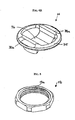
- the staple body 12 is shown in more detail in FIGS. 2A and 2B , and it can have a variety of configurations. In the illustrated exemplary embodiment, it has a substantially annular shape with a superior surface 12s, an inferior surface 12i, and a central opening 12o formed therethrough.
- the inferior surface 12i of the staple body 12 can include one or more bone-engaging members 26 formed thereon and adapted to extend into bone to prevent rotational movement of the staple 12 when the staple 12 is implanted.
- FIG. 2B illustrates multiple bone-engaging members 26 formed on and extending distally from the inferior surface 12i of the staple 12.
- the bone-engaging members 26 are in the form of spikes that are adapted to extend into bone, however they can have a variety of other shapes.
- the bone-engaging members 26 can vary in size.
- a mallet or other device can be used to apply a force to the staple 12 to impact the spikes into bone at the desired implant site, or a fastening element can be used to drive the staple 12 into bone, as will be discussed in more detail below.
- the central opening 12o in the staple body 12 can be adapted to receive a fastening element 14 therethrough to allow the fastening element 14 to mate the staple body 12 to bone. While the configuration of the central opening 12o can vary depending on the configuration of the fastening element 14, as will be discussed in more detail below with respect to Figure 3 , in one exemplary embodiment the central opening 12o has a substantially spherical, concave surface 22 formed therearound for seating a substantially spherical mating surface of the fastening element 14. The spherical surface 22 allows the fastening element 14 to be polyaxially movable with respect to the staple body 12, thereby allowing the fastening element 14 to be inserted into bone at an angle with respect to the staple body 12.
- the central opening 12o can have a variety of other configurations, and that the staple body 12 can include a fastening element integrally formed therewith or mated thereto.
- the staple body 12 can be swaged such that the fastening element 14 is integrated to the staple body 12 while allowing the fastening element 14 to rotate with respect to the staple body 12 to allow insertion into bone.
- the staple body 12 can also include opposed arms 20a, 20b formed on the superior surface 12s.
- the arms 20a, 20b can be adapted to couple to the locking assembly, thus the arms 20a, 20b can include a mating element formed thereof for mating with at least a portion of the locking assembly.
- each arm 20a, 20b can include threads 21a, 21b formed on an external surface thereof.
- the threads 21a, 21b can extend along the entire length of each arm 20a, 20b, or they can be formed only on a terminal portion of the arms 20a, 20b, as shown.
- the mating elements can have a square thread pattern.
- the particular configuration of each arm 20a, 20b can vary depending on the particular configuration of the locking mechanism, and a variety of other mating elements can be used to engage the locking assembly.
- the staple body 12 is adapted to seat a spinal fixation element.
- the superior surface 12s of the staple body 12 can define a pathway 12p formed between the opposed arms 20a, 20b.
- the pathway 12p can be adapted to seat a spinal fixation element between the opposed arms 20a, 20b such that the spinal fixation element extends across the superior surface 12s and the opening 12o.
- the spinal fixation element can be engaged between the locking assembly and the staple body 12 to maintain the spinal fixation element in a substantially fixed position.
- the pathway 12p can have a variety of configurations, and it can be linear or non-linear such that it changes direction, is tortuous, has curves or bends, etc.
- the superior surface 12s of the staple body 12 can also include features to facilitate engagement of a spinal fixation element between the locking assembly and the staple body 12.
- the superior surface 12s can include one or more protrusions (not shown) formed thereon and adapted to extend into a spinal fixation element, such as a tether, an exemplary embodiment of which will be described in more detail below.
- the superior surface 12s can include one or more ridges or grooves formed thereon for receiving one or more complementary grooves or ridges formed on the locking assembly.
- FIG. 2A illustrates two grooves 24a, 24b formed on opposed sides of the superior surface 12s of the staple body and positioned within the pathway 12p. The grooves 24a, 24b are adapted to receive complementary ridges formed on the washer of the locking assembly, as will be discussed in more detail with respect to FIGS. 4A and 4B .
- FIG. 3 illustrates one exemplary fastening element 14 that is in the form of a bone screw having a head 14b and a threaded shaft 14a that is adapted to extend into bone.
- the thread form of the threaded shaft 14a is preferably adapted for fixation in cancellous bone, and in certain exemplary embodiments the surface of the threaded shaft 14a can be treated to promote bone apposition.
- Techniques known in the art for promoting bone apposition include anodization and coating with materials containing calcium phosphate, collagen, bone growth factors, etc.
- the head 14b of the fastening element 14 can vary in shape and size depending on the configuration of the staple body 12, but in the illustrated exemplary embodiment the head 14b includes a flange 30 that is adapted to sit within the opening 12o in the staple body 12.
- the flange 30 can have a diameter that is greater than a diameter of the central opening 12o formed in the staple body 12 to prevent passage of the flange 30 therethrough.
- the flange 30 can also include a substantially spherical inferior surface (not shown) to allow the fastening element 14 to move polyaxially with respect to the staple body 12, as previously discussed.
- the head 14b of the fastening element 14 can also include a proximal extension 32 extending proximally from the flange 30.
- the proximal extension 32 which can be formed integrally with the shaft 14a of the bone screw 14, can include a recess 34 formed therein for receiving a tool adapted to drive the fastening element 14 into bone.
- the recess 34 can have any shape and size, but in the illustrated embodiment it has a hexagonal shape for receiving a hexagonal driver tool.
- the proximal extension 32 can extend into the pathway 12p that seats a spinal fixation element, such as a flexible tether.
- a spinal fixation element such as a flexible tether.
- Such a configuration is effective to create a bend or kink in the tether to substantially prevent sliding movement of the tether, or to otherwise facilitate engagement of the tether between the staple body 12 and the locking assembly.
- a polyaxial bone screw 14 is shown, the bone screw can be monoaxial or it can have a variety of other configurations. Other techniques for attaching the staple body 12 to bone may also be used.
- the spinal anchoring device 10 can also include a locking assembly that is adapted to mate to the staple body 12 to maintain a spinal fixation element, such as a tether, in a fixed position relative to the staple body 12.
- the configuration of the locking assembly can vary, and it can be formed from a single component or from multiple components.
- the locking assembly can also be separate from the staple body 12, or it can be coupled to the staple body and movable between an unlocked and a locked configuration.
- the locking assembly includes a washer 16 and a locking nut 18.
- the washer 16 is adapted to couple to the staple body 12 such that the tether is positioned between the washer 16 and the superior surface 12s of the staple body 12, and the locking nut 18 can be adapted to mate to the arms 20a, 20b of the staple body 12 to lock the washer 16 to the staple body 12, thereby locking the tether therebetween.
- FIGS. 4A and 4B An exemplary washer 16 is shown in more detail in FIGS. 4A and 4B , and as shown the washer 16 includes a generally annular member 35 with a strut 36 spanning across the annular member 35.
- the annular member 35 is adapted to be positioned around the opposed arms 20a, 20b of the staple body 12, and thus it can have a size that substantially corresponds to the size of the annular portion of the staple body 12.
- the strut 36 is adapted to be received between the opposed arms 20a, 20b and positioned within the pathway 12p of the staple body 12 to substantially prevent rotation of the washer 16 with respect to the staple body 12.
- Such a configuration is particularly advantageous in that the tether is protected from high, damaging shear forces.
- the strut 36 can be adapted to merely facilitate positioning of the washer 16 with respect to the staple body 12, or it can be adapted to engage a spinal fixation element, such as a tether, disposed within the pathway 12p.
- the strut 36 includes opposed legs 36a, 36b that extend outward from the annular member 35, and a connecting member 36c that extends between the opposed legs 36a, 36b.
- Such a configuration allows the connecting member 36c to be positioned a distance apart from the staple body 12, thereby allowing the extension 32 formed on the head 14b of the fastening element 14 to extend into the pathway 12p without abutting against the connecting member 36c of the strut 36.
- the height of the opposed legs 36a, 36b can, however, be varied based on the size of the spinal fixation element, and based on the intended use and whether the connecting member 36c is to engage the spinal fixation element.
- the strut 36 itself can vary in shape and size depending on the configuration of the staple body 12 and the spinal fixation element adapted to be disposed therein.
- the washer 16 can also include features to facilitate engagement of a spinal fixation element, such as a flexible tether, between the staple body 12 and the washer 16.
- a spinal fixation element such as a flexible tether
- FIG. 4B which illustrates the bottom of the washer 16
- the annular member 35 of the washer 16 can include opposed ridges 38a, 38b formed thereon and adapted to be received with the complementary grooves 24a, 24b formed in the staple body 12, as shown in FIG. 1B .
- the ridges 38a, 38b are preferably formed adjacent to the legs 36a, 36b of the strut 36 such that when the strut 36 is received between the opposed arms 20a, 20b of the staple body 12, the ridges 38a, 38b are aligned with and extend into the grooves 24a, 24b.
- the ridges 38a, 38b and grooves 24a, 24b will form a kink in the tether, thereby facilitating engagement such that the tether will be maintained in a substantially fixed position with respect to the device 10.
- the washer 16 can include one or more protrusions or spikes formed on the surface thereof for abutting or extending into the tether.
- the locking assembly can also include a locking nut 18 that is adapted to lock the washer 16 to the staple body 12.
- An exemplary locking nut 18, shown in more detail in FIG. 5 has a generally annular shape.
- the locking nut 18 can, however, have an external surface that is hexagonal or of some other shape that allows the locking nut 18 to be engaged by a wrench or other driver tool for rotating the locking nut 18.
- the locking nut 18 is adapted to be positioned around and to mate to the opposed arms 20a, 20b on the staple body 12.
- the locking nut 18 can include threads 18a formed therein for mating with the corresponding threads 21a, 21b formed on the arms 20a, 20b of the staple body 12.
- the locking nut 18 can be swaged to the washer 16 during manufacturing to integrate the two yet allow the nut 18 to be rotated with respect to the washer 16 during tightening of the closure mechanism.
- a variety of other mating techniques can also be used to mate the locking nut 18 to the body, including a snap-fit connection, an interference fit, etc.
- the locking assembly can have a variety of other configurations.
- the washer 16 itself can be adapted to mate to the staple body 12.
- the washer 16 can be a separate component, or it can be mated to the staple body 12 and movable between an open or unlocked position and a closed or locked position.
- the washer 16 may be connected to the staple body 12 by a hinge or the like.
- the locking nut 18 can be used without the washer 16 to fix the tether to the staple body 12.
- the locking nut 18 can be in the form of an inner set screw that mates to an inner surface of the legs 20a, 20b of the staple body 12.
- the device 10 is adapted to receive and engage a spinal fixation element.
- spinal fixation elements can be used, including both flexible and rigid fixation elements
- the spinal fixation element is a flexible tether.
- FIG. 6 illustrates one exemplary embodiment of a flexible tether 50, and as shown the tether 50 is substantially flat or planar. More particularly, the tether 50 can have a cross-sectional width w that is greater than a cross-sectional height h. In one exemplary embodiment, the width w can be at least two times greater than the height h.
- the width w can be in the range of about 4 mm to 8 mm, and preferably about 6 mm, and the height h can be in the range of about 0.5 mm to 2.5 mm, and preferably about 1.5 mm.
- the tether can have any number of different cross-sections, including square and round. In some preferred embodiments, the tether cross-section is square or round initially but then becomes flattened as the closure mechanism is tightened.
- the tether 50 can be made using a variety of techniques, but in one exemplary embodiment it is made using a flat braiding process. Other suitable processes include, for example, a 3-D weaving process.
- the properties of the tether 50 can also vary, but in an exemplary embodiment the tether has a tensile strength in the range of about 1 GPa to 5 GPa, and preferably about 3 GPa, and a tensile modulus in the range of about 10 GPa to 200 GPa, and preferably about 100 GPa.
- the materials used to form the tether can also vary, but suitable exemplary materials include polymers such as ultra-high molecular weight polyethylene (UHMWPE).
- UHMWPE ultra-high molecular weight polyethylene
- suitable exemplary materials include polymers such as ultra-high molecular weight polyethylene (UHMWPE).
- UHMWPE fibers include Dyneema® (manufactured by DSM) and Spectra® (manufactured by Allied Signal).
- Other materials that can be used for example, include polyethylene terephthalate (PET), nylon, Kevlar®, carbon, etc.
- PET polyethylene terephthalate
- the tether 50 can be made from a combination of materials, for example UHMWPE fibers combined with PET fibers.
- the tether 50 can also be made from bioabsorbable materials, such as poly(L-lactic acid) or other high strength, slowly degrading materials known in the art.
- the tether 50 can be positioned within the pathway 12p of the staple body 12 after the staple body 12 is implanted in bone.
- An impacting tool for driving the staple body 12 into bone can be used to implant the staple 12.
- the fastening element 16 can then be inserted therethrough to fix the staple body 12 to the bone.
- a driver tool can be used to drive the fastening element 16 into bone, thereby driving the staple body 12 into bone.
- the washer 14 can then be placed around the legs 20a, 20b of the staple body 12, and the locking nut 16 can be threaded onto the legs 20a, 20b to lock the washer 16 to the staple body 12, thereby locking the tether 50 to the device 10.
- the ridges 38a, 38b on the washer 16 will extend toward the grooves 24a, 24b on the staple body 12, thereby creating a kink or bend in the tether 50, further facilitating engagement of the tether 50 between the washer 16 and the staple body 12.
- Other exemplary methods and tools for implanting the spinal anchoring device 10 will be discussed in more detail below.
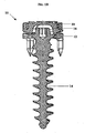
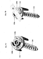
- FIGS. 7A-7F illustrate another exemplary embodiment of a spinal anchoring device 100.
- the device 100 is similar to spinal anchoring device 10 shown in FIG. 1A , and it includes a staple body 112, a fastening element 114, a washer 116, and a locking nut 118.
- the washer 116 does not include a strut. Rather, the washer 116 includes opposed legs 136a, 136b that extend from a substantially planar annular body 135.
- the legs 136a, 136b each include a flange 137a, 137b formed on the terminal end thereof and extending in opposed directions from one another.
- the flanges 137a, 137b are adapted to engage the locking nut 118 to allow the washer 116 and locking nut 118 to be mated to one another prior to mating the locking assembly to the staple body 12.
- the legs 136a, 136b can be flexible to allow the locking nut 118 to be inserted there over and mated to the washer 116.
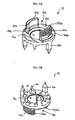
- FIGS. 7C-7F illustrate assembly of the device, and as shown the tether 50 is positioned in the pathway in the staple body 112.
- the washer 116 and locking nut 118 can be mated to one another, as shown in FIG. 7F , and then they can be mated to the staple body 112.
- the mating configuration of the washer 116 and the locking nut 118 allows the locking nut 118 to rotate freely with respect to the washer 116, thereby allowing the washer 116 to maintain a substantially fixed position with respect to the staple body 112, while the locking nut 118 is threaded onto the arms 120a, 120b of the staple body 112.
- This is particularly advantageous as the legs 136a, 136b of the washer 116 will be positioned between the arms 120a, 120b of the staple body 112, thereby preventing the washer 116 from rotating with respect to the staple body 112.
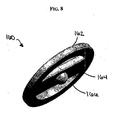
- FIG. 8 illustrates another exemplary embodiment of a washer 160 for use with a spinal anchoring device.
- the washer 160 has a substantially planar annular member 162 with a substantially planar strut 164 extending thereacross.
- the washer 160 also includes a tether-engaging protrusion 166 formed thereon.
- the opposed arms of a staple body such as arms 20a, 20b of staple 12 shown in FIG. 1A
- the strut 164 extends between the opposed arms 20a, 20b.
- the planar configuration of the washer 160 will cause the washer 160 to engage the tether 50 between the staple body 12 and the washer 160.
- the protrusion 166 formed on the strut 164 will abut and deform the tether 50, thereby engaging the tether 50 to substantially prevent movement of the tether 50 with respect to the device. Since the washer 160 is substantially planar, the head of the fastening element used with the staple body preferably does not extend into the tether pathway formed in the staple body, as such a configuration would cause the strut 164 to abut against the head of the fastening element.
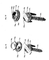
- FIGS. 9A-9D illustrate yet another embodiment of a spinal anchoring device 200.
- the device 200 includes a staple body 212, fastening element 214, and a locking nut 218 that are similar to staple body 12, fastening element 14, and locking nut 18 shown in FIG. 1A .
- a clip 216 is used to engage the tether 50.
- the clip 216 can be adapted to be disposed around a spinal fixation element, such as tether 50, and it can be adapted to be positioned within the pathway of the staple body 12 and disposed between the staple body 12 and the locking nut 218.
- the shape and size of the clip 216 can vary depending on the shape and size of the spinal anchoring device used therewith, in an exemplary embodiment the clip 216 has a substantially elongate shape with opposed arms 216a, 216b that define a track or recess therebetween for seating the tether 50.
- the arms 216a, 216b can extend around the tether 50 to engage the tether 50.
- the clip 216 can be formed from a pliable or deformable material to allow the clip 216 to deform around the tether 50 when the locking nut 18 is applied to the staple body 12.
- FIG. 9C illustrates the clip 216 disposed around the tether 50 with the locking nut 218 about to be mated to the staple body 212.
- FIG. 9D illustrates the locking nut 218 threaded onto the staple body 212, and as shown the clip 216 is deformed by the locking nut 218 such that the clip 216 engages the tether 50 to prevent sliding movement thereof relative to the device 200.
- the clip is a deformable tube that serves to protect the tether while tightening the locking nut. In yet another embodiment, the clip does not deform upon tightening the locking nut, thereby allowing the tether to slide within the closure mechanism.
- FIGS. 10A-1OC illustrate yet another exemplary embodiment of a spinal anchoring device 300.
- the device 300 includes a staple body 312 and fastening element 314 that are similar to staple body 12 and fastening element 14 shown in FIG. 1A .
- the staple body 312 does not include opposed arms formed thereon, but rather has a substantially planar superior surface 312s, and the fastening element 314 has a substantially planar head 314a formed thereon such that the head 314a is co-planar with, or recessed with respect to, the superior surface 312s of the staple body 312.
- the staple body 312 also includes several mating elements formed thereon for mating to the locking assembly. While the mating elements can have a variety of configurations, in the exemplary embodiment illustrated in FIGS. 10A-10C the staple body 312 includes cut-outs 312a, 312b, 312c, 312d formed therein for receiving tabs formed on the locking mechanism.
- the locking mechanism includes first and second members 316a, 316b that are adapted to mate to opposed sides of the superior surface 312s of the staple body 312 to engage the tether 50 therebetween.
- the first and second members 316a, 316b can be integrally formed as a single member that mates to the staple body 312.
- Each members 316a, 316b can have a substantially semi-circular shape with mating elements formed thereon for engaging the complementary corresponding mating elements formed on the superior surface 312s of the staple body 312.
- the members 316a, 316b each includes two tabs formed thereon. Only two tabs 317a, 317b are shown formed on the first member 316a.
- Each tab 317a, 317b is adapted to extend into the corresponding cut-out 312a, 312b, 312c, 312d formed in the staple body 312 to engage the staple body 312 by a snap-fit or interference fit.
- a tether 50 can be positioned across the staple body 312, e.g., in the pathway, and the first and second members 316a, 316b can then be mated to the staple body 312, as shown in FIG. 10C , to engage the tether 50 therebetween.
- each member 316a, 316b is positioned such that the tabs 317a, 317b are positioned on opposed sides of the tether 50, thereby allowing the annular portion of the members 316a, 316b to engage the tether 50.
- the tether 50 can optionally be twisted to form one or more twists 51 between the two members 316a, 316b, thereby further preventing slidable movement of the tether 50 with respect to the device 300.
- the spinal anchoring device can have a variety of other configurations, and it can include a combination of various features disclosed herein, as well as other features to facilitate engagement of a spinal fixation element, such as a tether.
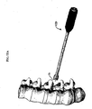
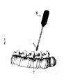
- FIG. 11A a staple inserter 400 is shown for inserting the staple body 12 of device 10 into bone.
- the exemplary staple inserter 400 shown in more detail in FIG. 11B , includes a generally elongate hollow shaft 402 having a proximal end with a handle 404 formed thereon, and a distal end with a staple-engaging member 406 formed thereon.
- the staple-engaging member 406 is adapted to engage the staple body 12, to allow the body 12 to be positioned relative to a vertebra, as shown in FIG.
- the staple-engaging member 406 can vary depending on the shape and size of the staple body 12, in an example the staple-engaging member includes opposed deflectable members 408a, 408b that are separated by an elongate slot 410.
- the elongate slot 410 extends proximally from the distal-most end of the device 400 to allow the opposed deflectable members 408a, 408b to deflect relative to one another.
- the length of the elongate slot 410 can vary depending on the desired flexibility of the deflectable members. As is further shown in FIGS.
- the opposed deflectable members 408a, 408b can include a substantially cylindrical distal portion having a recess 412 formed in a distal surface thereof for receiving the staple body 12.
- the recess 412 has a substantially rectangular shape for receiving the arms 20a, 20b formed on the staple body 12, as shown in FIG. 11C .
- the staple body 12 can be engaged by the opposed deflectable members 408a, 408b by placing the deflectable members 408a, 408b over the staple body 12, thereby causing the members 408a, 408b to deflect around the arms 20a, 20b to engage the arms 20a, 20b.
- the staple inserter tool 400 can then be manipulated to place the staple 12 into a vertebrae.
- the handle 404 of the tool 400 can be impacted to impact the staple body 12 into bone.
- the fastening element 14 can be used to drive the staple 12 into bone.
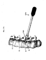
- FIG. 12A illustrates an awl 420 inserted through the hollow elongate shaft 402 of the inserter tool 400.
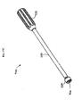
- the awl 420 is shown in more detail in FIG. 12B , and as shown it has a generally elongate shaft 422 with a proximal handle 424 and a distal bone-penetrating tip 426 for starting a bone hole.
- FIG. 12B illustrates an awl 420 inserted through the hollow elongate shaft 402 of the inserter tool 400.
- the awl 420 is shown in more detail in FIG. 12B , and as shown it has a generally elongate shaft 422 with a proximal handle 424 and a distal bone-penetrating tip 426 for starting a bone hole.
- FIG. 12C illustrates the distal end of the inserter tool 400 showing the bone-penetrating tip 426 of the awl 420 extending through the central opening in the staple body 12.
- the awl 420 is inserted through the inserter tool 400 and an impacting force is applied to the handle 424 to drive the bone-penetrating tip 426 into bone. Consequently, the driving force applied to the awl 420 can be used to drive the staple body 12 into bone as well.
- the staple inserter tool 400 and awl 420 can be removed, leaving the staple implanted in the vertebrae.
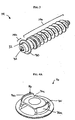
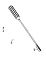
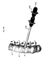
- a tap 460 can then be used to form threads within the bone hole, as shown in FIG. 13A , thereby preparing the bone hole for receiving the fastening element 14.
- the tap 460 which is shown in more detail in FIG. 13B , is similar to the awl 420 except that it includes a threaded shaft 462 formed on the distal end thereof.
- the tap can be inserted through the staple inserter to form threads within the bone hole.
- the fastening element 14 can be inserted through the staple body 12 and into the bone hole to fixedly secure the staple body 12 to the vertebra.
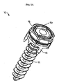
- FIG. 14 illustrates the fastening element 14 about to be inserted into the bone hole using a driver tool 480. This procedure can be repeated to implant additional spinal anchoring devices one or more adjacent vertebrae.
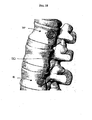
- FIG. 15 shows two spinal anchoring devices 10, 10' implanted in two vertebrae in a patient's spinal column.
- FIG. 16A illustrates tether 50 extending between spinal anchoring devices 10, 10'.
- a locking assembly can then be applied to each spinal anchoring device 10, 10' to lock the tether 50 relative thereto.
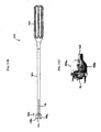
- a fastener inserter tool 500 can be used to apply the fastening element, e.g., the washer 16 and locking nut 18, as is also shown in FIG. 16A .
- the exemplary inserter tool 500 which is shown in more detail in FIGS.
- 16B and 16C has a generally elongate shaft 502 with a distal end having a substantially cylindrical shape with opposed arms 504a, 504b formed thereon.
- the arms 504a, 504b are adapted to receive and engage the strut 36 of the washer 16, thereby mating the washer 16, as well as the locking nut 18 which is disposed around the washer 16, to the inserter tool 500.
- the inserter tool 500 can then be manipulated to position the washer 16 and locking nut 18 over the arms 20a, 20b of the staple body 12.
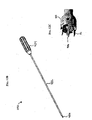
- the fastener inserter tool 500 can also include a wrench 520 that is adapted to be slidably disposed over the fastener inserter tool 500 and that is adapted to engage and rotate the locking nut 18, as shown in FIGS. 17A and 17B .
- the wrench 520 is shown in more detail in FIG. 17C , and as shown it has a generally elongate hollow shaft 522 with a proximal handle 524 and a distal socket member 526 formed thereon.
- the socket member 526 includes a socket 528 formed therein and having a shape that corresponds to a shape of the locking nut 18.
- the socket member 526 includes a hexagonal socket 528 formed therein for mating with the hexagonal outer surface of the locking nut 18.
- the wrench 520 is inserted over the fastener inserter tool 500 until the locking nut 18 is received within the socket 528.
- the handle 524 of the wrench 520 is then rotated to rotate the locking nut 18, thereby threading the locking nut 18 onto the staple body 12.
- tether 50 is engaged between the washer 16 and the staple body 12 such that it is maintained in a substantially fixed position.
- Additional locking assemblies can be applied to additional spinal anchoring devices to lock the tether 50 thereto.
- Tension can be applied to the tether 50 between each anchoring device prior to or while applying the locking assemblies to achieve a desired result.
- FIG. 18 illustrates tether 50 extending between two spinal anchoring devices 10, 10'.
- FIG. 18 illustrates a single tether 50 positioned on one side of the spine
- multiple tethers can be used depending on the deformities to be corrected.
- the tether is preferably positioned on the concave side of a deformed spinal curve, thereby halting growth on the convex side of the deformity.
- multiple tethers can be used.
- three spinal anchoring devices can be placed in the sagittal plane on the concave side of the curve in the spinal column at a first level, and three additional spinal anchoring devices can be placed on the opposed side of the spinal column at a second level such that the three additional spinal anchoring devices are placed on the concave side of a second curvature formed in the spinal column.
- a tether can thus be positioned to span between the spinal anchoring devices at the first level, and a second tether can be positioned to span between the spinal anchoring devices at the second level on the opposite side of the spine. Tension can then be applied to each tether and the tethers can be locked relative to each spinal anchoring device as previously discussed.
- the tension between each vertebra can vary depending on the desired correction, which can be accomplished intraoperatively by tensioning the tethers to achieve the correction immediately, and/or by allowing normal growth of the spine to achieve correction by asymmetrically restricting growth using the tether.
- the tethers can optionally be cut to release the tension at one or more levels.
- the tethers can be cut in a minimally invasive procedure. Cutting the tethers is particularly advantageous to prevent over-correction.
- both tethers can be placed on the convex side of the curve, with one posterior tether and one anterior tether.
- the tethers can be mated to the vertebrae by several spinal anchoring devices that are implanted adjacent to one another within each of several adjacent vertebrae. Tension can then be applied to both the anterior and posterior tethers by selectively fastening the anchoring devices to lock the tethers therein.
- equal tension is preferably applied to both tethers, and the degree of tension dictates how much correction is achieved intraoperatively and how much is left to take place during asymmetric growth restriction.
- the anterior and posterior tethers are preferably tensioned differently.
- the posterior tether is tightened more than the anterior tether.
- the anterior tether a is tightened more than the posterior tether. Similar to correcting the scoliotic deformity, the degree of tension dictates how much correction is achieved intraoperatively and how much is left to take place during asymmetric growth restriction.
- the implants and instruments described herein are designed to be used in a minimally invasive surgical procedure; thus the dimensions are such that they can be inserted through a portal with an inner diameter of approximately 5 to 30 mm, more preferably 15 to 20 mm. This is particularly important when the implants are being used to correct a cosmetic deformity, where lengthy incisions would negate the positive cosmetic effect of the correction.
Abstract
Description
- Spinal deformities, which include rotation, angulation, and/or curvature of the spine, can result from various disorders, including, for example, scoliosis (abnormal curvature in the coronal plane of the spine), kyphosis (backward curvature of the spine), and spondylolisthesis (forward displacement of a lumbar vertebra). Early techniques for correcting such deformities utilized external devices that apply force to the spine in an attempt to reposition the vertebrae. These devices, however, resulted in severe restriction and in some cases immobility of the patient. Furthermore, current external braces have limited ability to correct the deformed spine and typically only prevent progression of the deformity. Thus, to avoid this need, several rod-based techniques were developed to span across multiple vertebrae and force the vertebrae into a desired orientation.
- In rod-based techniques, one or more rods are attached to the vertebrae at several fixation sites to progressively correct the spinal deformity. The rods are typically pre-curved intraoperatively to a desired adjusted spinal curvature. Wires as well as bone screws can be used to pull individual vertebra toward the rod. Once the spine has been substantially corrected, the procedure typically requires fusion of the instrumented spinal segments.
- While several different rod-based systems have been developed, they tend to be cumbersome, requiring complicated surgical procedures with long operating times to achieve correction. Further, intraoperative adjustment of rod-based systems can be difficult and may result in loss of mechanical properties due to multiple bending operations. The rigidity and permanence of rigid rod-based systems can also hinder or prevent growth of the spine and they generally require fusion of many spine levels, drastically reducing the flexibility of the spine. In addition to excessive rigidity, other drawbacks with current devices include dislodgement and a high profile.
- US Patent Publication No.
US-2002/0055739 discloses an apparatus for correcting spinal deformity which comprises bone anchors for implantation into a vertebral body. One disclosed apparatus, shown in Figs. 43-46, has a bone anchor including a platform, a slot for receiving a bar and a fastener portion comprising a shaft with an external thread convolution for engaging vertebrae. The apparatus also includes a staple which has a generally rectangular shape with an opening for receiving the platform of the bone anchor. To implant the anchor, a pilot hole is drilled in a vertebra and the fastener portion of the bone anchor is placed in the hole. A rotatable driver is used to rotate the anchor into bone of the vertebra until an end surface of the platform seats against a surface of the vertebra. The staple is then placed over the platform of the anchor, and force applied to drive projections on the staple into the vertebra until a lower surface of the staple contacts the surface of the vertebra. In this position, inwardly facing surfaces of the staple engage the periphery of the bone anchor platform to block relative movement between the anchor and the staple. Once two or more of the anchors have been inserted, the bar is positioned and secured using nuts. Another apparatus, shown inFigs. 1-7 , discloses the features of the preamble of claim 1. - There remains a need for improved devices for correcting spinal deformities and, in particular, there remains a need for low-profile, flexible non-fusion spinal correction devices.
- The present invention provides devices for treating spinal deformities according to claim 1. A spinal anchoring device is provided and it includes a staple body, a fastening element, and a locking assembly. The staple body is adapted to receive the fastening element for mating the staple body to bone, and to seat a tether. The locking assembly can be applied to the staple body to engage the tether and substantially prevent movement thereof relative to the device.
- While the staple body can have a variety of configurations, in one embodiment the staple body includes a central opening formed therethrough and a pathway extending across the central opening for seating a tether. In an exemplary embodiment, the central opening includes a substantially spherical surface formed therearound for seating a complementary spherical surface formed on the fastening element. The staple body can also include opposed arms extending from opposed sides of a superior surface. The opposed arms can define the pathway therebetween. The configuration of the pathway can vary, but in one exemplary embodiment the pathway is non-linear, and more preferably it is tortuous. In another embodiment, the opposed arms can include threads formed on an external surface thereof for mating with corresponding threads formed on the locking assembly.
- The fastening element can also have a variety of configurations, but in one embodiment the fastening element is adapted to extend through a central opening formed in the staple body to mate the staple body to bone. By way of non-limiting example, the fastening element can be a bone screw having a head and a shank. In an exemplary embodiment, the head of the bone screw includes a flange formed just distal to a proximal end of the shank of the bone screw and having a diameter that is greater than a diameter of the central opening formed in the staple body. The flange can also include a substantially spherical inferior surface that is adapted to correspond to a substantially spherical surface formed around the central opening of the staple body. The head of the bone screw can also include a proximal extension that is adapted to extend into the pathway of the staple body. The proximal extension can include a recess formed therein for receiving a tool adapted to drive the bone screw into bone.
- The locking assembly is adapted to engage the staple body such that a tether extending through the pathway extends between the locking assembly and the staple body. In an exemplary embodiment, the locking assembly includes a washer that is adapted to couple to the staple body such that a tether extending through the pathway is positioned between the washer and the staple body, and a locking nut that is adapted to engage the staple body to lock the washer to the staple body. While the shape of the washer can vary, one exemplary washer includes opposed openings formed therethrough for receiving the opposed arms on the staple body. The washer can also include a strut extending thereacross and adapted to be positioned between the opposed arms. In other exemplary embodiments, the locking assembly can be a nut, such as a set screw, or a washer that is separate from the staple body, or that is coupled to the staple body and movable between an open position and a closed position.
- In yet another embodiment, the spinal anchoring device can include a deformable clip that is adapted to be disposed around a tether and positioned within the pathway such that the locking assembly is adapted to deform the clip to engage the tether when the locking assembly is mated to the staple body.
- In other embodiments, the staple, the fastening element, and/or the locking assembly can include a tether-engaging feature formed thereon. In one exemplary embodiment, the tether-engaging features can be at least one groove formed on the superior surface of the staple and positioned in the pathway, and at least one complementary ridge formed on the locking assembly such that the at least one ridge and at least one groove are adapted to engage a tether seated in the pathway. In another embodiment, the tether-engaging feature can be a head formed on a proximal end of the fastening element and adapted to extend into the pathway such that the head alters a path of a tether seated in the pathway. In yet another embodiment, the tether-engaging feature can be a protrusion formed on an inferior surface of the locking assembly such that the protrusion is adapted to extend into a tether seated in the pathway.
- An exemplary tether of a spinal anchoring device is in the form of a substantially flat elongate member preferably having a cross-sectional width that is at least two times greater than a cross-sectional height. In an exemplary embodiment, the tether is formed from a biocompatible polymeric braided material, such as an ultra-high molecular weight polyethylene, or poly(ethylene terephthalate). In other embodiments, the tether can be formed from a bioabsorble material, such as poly(L-lactic acid).
- An exemplary spinal anchoring system is also provided, which includes a substantially flat elongate tether, and an anchoring device that is adapted to mate to bone and that includes a pathway formed therethrough for seating the substantially flat elongate tether such that the tether is maintained in a substantially fixed position. The anchoring device includes a staple that is adapted to penetrate bone and defining the pathway, a fastening element that is adapted to mate the staple to bone, and a locking assembly that is adapted to engage the staple to maintain the tether in a substantially fixed position between the locking assembly and the staple. The staple may include opposed arms, and the locking assembly may be adapted to receive the opposed arms therethrough to mate to the staple. The locking assembly may comprise a washer and a locking nut, and the locking nut may include a mating element formed thereon and adapted to mate to a complementary mating element formed on the opposed arms. The staple may include opposed arms, and the locking assembly may be adapted to receive the opposed arms therethrough to mate to the staple.
- In certain aspects, the anchoring device can include at least one tether-engaging feature that is adapted to extend into the pathway to maintain the tether in a substantially fixed position. The tether-engaging feature can be, for example, a clip that is adapted to be disposed around the tether. In other embodiments, the tether-engaging feature can be a ridge formed on an inferior surface of the washer for extending into at least one corresponding complementary groove formed in a superior surface of the staple. The ridge(s) and the groove(s) can be adapted to engage the tether therebetween. The washer may include a strut extending thereacross and adapted to be received between the opposed arms of the staple. The fastening element may comprise a bone screw having a head and a threaded shank, and the staple may include a central opening formed therein for receiving the bone screw. The head of the bone screw may be adapted to extend into the pathway of the staple body.
- The invention will be more fully understood from the following detailed description taken in conjunction with the accompanying drawings, in which:
-
FIG. 1A is a perspective view of one exemplary embodiment of a spinal anchoring device; -
FIG. 1B is a cross-sectional view of the spinal anchoring device shown inFIG. 1A ; -
FIG. 2A is a top perspective view of a staple body of the spinal anchoring device shown inFIG. 1A ; -
FIG. 2B is a bottom perspective view of the staple body shown inFIG. 2A ; -
FIG. 3 is a perspective view a fastening element of the spinal anchoring device shown inFIG. 1A ; -
FIG. 4A is a top perspective view of a washer that forms part of the locking assembly of the spinal anchoring device shown inFIG. 1A ; -
FIG. 4B is a bottom perspective view of the washer shown inFIG. 4A ; -
FIG. 5 is a perspective view of a locking nut that forms part of the locking assembly of the spinal anchoring device shown inFIG. 1A ; -
FIG. 6 is a perspective view of one exemplary embodiment of a flat flexible tether; -
FIG. 7A is a perspective view of another exemplary embodiment of a spinal anchoring device having a tether coupled thereto by a locking mechanism; -
FIG. 7B is a cross-sectional view of the spinal anchoring device shown inFIG. 7A ; -
FIG. 7C is a perspective view of the spinal anchoring device shown inFIG. 7A without the tether and the locking mechanism coupled thereto; -
FIG. 7D is a perspective view of the spinal anchoring device shown inFIG. 7C showing the tether extending through a pathway formed therein; -
FIG. 7E is a perspective view of the spinal anchoring device shown inFIG. 7D showing the locking mechanism about to be coupled thereto and having a locking nut and a washer; -
FIG. 7F is a perspective view of the spinal anchoring device shown inFIG. 7E showing the locking nut and washer of the locking mechanism coupled to one another; -
FIG. 8 is a perspective view of another embodiment of a washer for use with a spinal anchoring device; -
FIG. 9A is a perspective, disassembled view of another exemplary embodiment of a spinal anchoring device having a clip for engaging a tether extending therethrough; -
FIG. 9B is a perspective, assembled view of the spinal anchoring device shown inFIG. 9A having the tether extending therethrough; -
FIG. 9C is a cross-sectional view of a portion of the spinal anchoring device shown inFIG. 9A with the locking mechanism about to be coupled thereto; -
FIG. 9D is a cross-sectional view of a portion of the spinal anchoring device shown inFIG. 9C with the locking mechanism coupled thereto; -
FIG. 10A is a perspective, disassembled view of yet another exemplary embodiment of a spinal anchoring device having a tether extending therethrough and having a two-piece locking element; -
FIG. 10B is a perspective, partially assembled view of the spinal anchoring device shown inFIG. 10A having the tether extending therethrough with a twist formed therein; -
FIG. 10C is a perspective, fully assembled view of the spinal anchoring device shown inFIG. 10B having the tether extending therethrough; -
FIG. 11A is an illustration showing a staple inserter tool about to implant a staple of a spinal anchoring device in a vertebra; -
FIG. 11B is a perspective view of the staple inserter tool shown inFIG. 11A ; -
FIG. 11C is a perspective view of a distal end of the staple inserter tool shown inFIG. 11B with a staple coupled thereto; -
FIG. 12A is an illustration showing an awl inserted through the staple inserter tool and staple shown inFIG. 11A for preparing a bone hole; -
FIG. 12B is a perspective view of the awl shown inFIG. 12A ; -
FIG. 12C is a perspective view of a distal end of the awl shown inFIG. 12B inserter through the staple inserter tool and staple shown inFIG. 12A ; -
FIG. 13A is an illustration showing a tap about to be inserted through the staple implanted in the vertebrae for forming threads in the bone hole prepared by the awl; -
FIG. 13B is a perspective view of the tap shown inFIG. 13A ; -
FIG. 14 is an illustration showing a driver tool about the implant a fastening element through the staple and into the bone hole; -
FIG. 15 is an illustration showing two spinal anchoring devices implanted in two vertebrae; -
FIG. 16A is an illustration showing a tether positioned relative to the two spinal anchoring devices implanted in the vertebrae shown inFIG. 15 , and showing a fastener inserter tool about to apply a fastening element to one of the spinal anchoring devices; -
FIG. 16B is a perspective view of the fastener inserter tool shown inFIG. 16A ; -
FIG. 16C is a perspective view of a distal portion of the fastener inserter tool shown inFIG. 16B showing a fastening element coupled thereto; -
FIG. 17A is an illustration showing the fastening element applied to the spinal anchoring device using the fastener inserter tool shown inFIG. 16A , and showing a wrench inserted over the driver; -
FIG. 17B is an illustration showing the wrench ofFIG. 17A being rotated relative to the drive to rotate a locking nut of the locking mechanism; -
FIG. 17C is a perspective view of the wrench shown inFIGS. 17A and17B ; and -
FIG. 18 is an illustration showing a tether extending between and coupled to two spinal anchoring devices implanted in two vertebrae. - Certain exemplary embodiments will now be described to provide an overall understanding of the principles of the structure, function, manufacture, and use of the devices disdosed herein. One or more examples of these embodiments are illustrated in the accompanying drawings. Those skilled in the art will understand that the devices specifically described herein and illustrated in the accompanying drawings are non-limiting exemplary embodiments and that the scope of the present invention is defined solely by the claims. The features illustrated or described in connection with one exemplary embodiment may be combined with the features of other embodiments.
- In one exemplary embodiment, a low-profile spinal anchoring device is provided for receiving a spinal fixation element, such as a tether, therethrough. In use, several spinal anchoring devices can be implanted in several adjacent vertebrae, and the tether can be coupled to the spinal anchoring devices to halt growth of the spine on the side where the tether is applied. By halting the growth of the spine on the convex side of the deformity, subsequent growth of the spine on the concave side will cause the deformity to self-correct, thus gradually providing the correction while allowing the patient's overall height to increase. The devices can, however, be used in a variety of other spinal applications. By way of non-limiting example, the spinal anchoring devices and/or tethers disclosed herein can be used for intraoperative deformity correction with subsequent fusion, as taught by Dr. A. F. Dwyer in the 1960's and 70's (clip Orthop Rel Res 93, pp. 191-206, 1973, and J Bone Joint Surg 56B, pp. 218-224). In addition, they can be used for posterior dynamization to function as a decompressive device for stenosis and/or an adjunct to an intervertebral disc to unload the facets of the vertebra. A variety of exemplary methods and tools for implanting a spinal anchoring device are also described.
-
FIGS. 1A and1B illustrate one exemplary embodiment of aspinal anchoring device 10. As shown, thedevice 10 generally includes astaple body 12 that is adapted to seat a spinal fixation element, afastening element 14 for fixing thestaple body 12 to bone, and a locking assembly for coupling a spinal fixation element to thestaple body 12. In the illustrated exemplary embodiment, the locking assembly includes awasher 16 that is adapted to couple to thestaple body 12 such that the spinal fixation element is disposed therebetween, and a lockingnut 18 that is adapted to engage thestaple body 12 to mate thewasher 16 to thestaple body 12. The locking assembly can, however, have a variety of other configurations and it can be separate from the staple body or coupled to the staple body. - The
staple body 12 is shown in more detail inFIGS. 2A and 2B , and it can have a variety of configurations. In the illustrated exemplary embodiment, it has a substantially annular shape with a superior surface 12s, an inferior surface 12i, and a central opening 12o formed therethrough. The inferior surface 12i of thestaple body 12 can include one or more bone-engagingmembers 26 formed thereon and adapted to extend into bone to prevent rotational movement of the staple 12 when the staple 12 is implanted.FIG. 2B illustrates multiple bone-engagingmembers 26 formed on and extending distally from the inferior surface 12i of thestaple 12. The bone-engagingmembers 26 are in the form of spikes that are adapted to extend into bone, however they can have a variety of other shapes. As is further shown, the bone-engagingmembers 26 can vary in size. In use, a mallet or other device can be used to apply a force to the staple 12 to impact the spikes into bone at the desired implant site, or a fastening element can be used to drive the staple 12 into bone, as will be discussed in more detail below. - The central opening 12o in the
staple body 12 can be adapted to receive afastening element 14 therethrough to allow thefastening element 14 to mate thestaple body 12 to bone. While the configuration of the central opening 12o can vary depending on the configuration of thefastening element 14, as will be discussed in more detail below with respect toFigure 3 , in one exemplary embodiment the central opening 12o has a substantially spherical, concave surface 22 formed therearound for seating a substantially spherical mating surface of thefastening element 14. The spherical surface 22 allows thefastening element 14 to be polyaxially movable with respect to thestaple body 12, thereby allowing thefastening element 14 to be inserted into bone at an angle with respect to thestaple body 12. A person skilled in the art will appreciate that the central opening 12o can have a variety of other configurations, and that thestaple body 12 can include a fastening element integrally formed therewith or mated thereto. For example, thestaple body 12 can be swaged such that thefastening element 14 is integrated to thestaple body 12 while allowing thefastening element 14 to rotate with respect to thestaple body 12 to allow insertion into bone. - As further shown in
FIGS. 2A and 2B , thestaple body 12 can also include opposed arms 20a, 20b formed on the superior surface 12s. As will be discussed in more detail below, the arms 20a, 20b can be adapted to couple to the locking assembly, thus the arms 20a, 20b can include a mating element formed thereof for mating with at least a portion of the locking assembly. As shown inFIGS. 2A and 2B , each arm 20a, 20b can includethreads 21a, 21b formed on an external surface thereof. Thethreads 21a, 21b can extend along the entire length of each arm 20a, 20b, or they can be formed only on a terminal portion of the arms 20a, 20b, as shown. In one exemplary embodiment of the invention, the mating elements can have a square thread pattern. The particular configuration of each arm 20a, 20b can vary depending on the particular configuration of the locking mechanism, and a variety of other mating elements can be used to engage the locking assembly. - In use, the
staple body 12 is adapted to seat a spinal fixation element. Accordingly, the superior surface 12s of thestaple body 12 can define apathway 12p formed between the opposed arms 20a, 20b. Thepathway 12p can be adapted to seat a spinal fixation element between the opposed arms 20a, 20b such that the spinal fixation element extends across the superior surface 12s and the opening 12o. As a result, when the locking assembly is applied to thestaple body 12, the spinal fixation element can be engaged between the locking assembly and thestaple body 12 to maintain the spinal fixation element in a substantially fixed position. A person skilled in the art will appreciate that thepathway 12p can have a variety of configurations, and it can be linear or non-linear such that it changes direction, is tortuous, has curves or bends, etc. - The superior surface 12s of the
staple body 12 can also include features to facilitate engagement of a spinal fixation element between the locking assembly and thestaple body 12. By way of non-limiting example, the superior surface 12s can include one or more protrusions (not shown) formed thereon and adapted to extend into a spinal fixation element, such as a tether, an exemplary embodiment of which will be described in more detail below. In other embodiments, the superior surface 12s can include one or more ridges or grooves formed thereon for receiving one or more complementary grooves or ridges formed on the locking assembly.FIG. 2A illustrates two grooves 24a, 24b formed on opposed sides of the superior surface 12s of the staple body and positioned within thepathway 12p. The grooves 24a, 24b are adapted to receive complementary ridges formed on the washer of the locking assembly, as will be discussed in more detail with respect toFIGS. 4A and4B . - As previously mentioned, the
staple body 12 can be adapted to receive afastening element 14 through the central opening 12o. While thefastening element 14 can have a variety of configurations,FIG. 3 illustrates oneexemplary fastening element 14 that is in the form of a bone screw having a head 14b and a threaded shaft 14a that is adapted to extend into bone. The thread form of the threaded shaft 14a is preferably adapted for fixation in cancellous bone, and in certain exemplary embodiments the surface of the threaded shaft 14a can be treated to promote bone apposition. Techniques known in the art for promoting bone apposition include anodization and coating with materials containing calcium phosphate, collagen, bone growth factors, etc. The head 14b of thefastening element 14 can vary in shape and size depending on the configuration of thestaple body 12, but in the illustrated exemplary embodiment the head 14b includes a flange 30 that is adapted to sit within the opening 12o in thestaple body 12. The flange 30 can have a diameter that is greater than a diameter of the central opening 12o formed in thestaple body 12 to prevent passage of the flange 30 therethrough. The flange 30 can also include a substantially spherical inferior surface (not shown) to allow thefastening element 14 to move polyaxially with respect to thestaple body 12, as previously discussed. - The head 14b of the
fastening element 14 can also include aproximal extension 32 extending proximally from the flange 30. Theproximal extension 32, which can be formed integrally with the shaft 14a of thebone screw 14, can include a recess 34 formed therein for receiving a tool adapted to drive thefastening element 14 into bone. The recess 34 can have any shape and size, but in the illustrated embodiment it has a hexagonal shape for receiving a hexagonal driver tool. - In use, when the
fastening element 14 is disposed through the central opening 12o of thestaple body 12, theproximal extension 32 can extend into thepathway 12p that seats a spinal fixation element, such as a flexible tether. Such a configuration is effective to create a bend or kink in the tether to substantially prevent sliding movement of the tether, or to otherwise facilitate engagement of the tether between thestaple body 12 and the locking assembly. A person skilled in the art will appreciate that, while apolyaxial bone screw 14 is shown, the bone screw can be monoaxial or it can have a variety of other configurations. Other techniques for attaching thestaple body 12 to bone may also be used. - As discussed with respect to
FIGS. 1A and1B , thespinal anchoring device 10 can also include a locking assembly that is adapted to mate to thestaple body 12 to maintain a spinal fixation element, such as a tether, in a fixed position relative to thestaple body 12. The configuration of the locking assembly can vary, and it can be formed from a single component or from multiple components. The locking assembly can also be separate from thestaple body 12, or it can be coupled to the staple body and movable between an unlocked and a locked configuration. In the illustrated exemplary embodiment, the locking assembly includes awasher 16 and a lockingnut 18. Thewasher 16 is adapted to couple to thestaple body 12 such that the tether is positioned between thewasher 16 and the superior surface 12s of thestaple body 12, and the lockingnut 18 can be adapted to mate to the arms 20a, 20b of thestaple body 12 to lock thewasher 16 to thestaple body 12, thereby locking the tether therebetween. - An
exemplary washer 16 is shown in more detail inFIGS. 4A and4B , and as shown thewasher 16 includes a generallyannular member 35 with astrut 36 spanning across theannular member 35. Theannular member 35 is adapted to be positioned around the opposed arms 20a, 20b of thestaple body 12, and thus it can have a size that substantially corresponds to the size of the annular portion of thestaple body 12. Thestrut 36 is adapted to be received between the opposed arms 20a, 20b and positioned within thepathway 12p of thestaple body 12 to substantially prevent rotation of thewasher 16 with respect to thestaple body 12. Such a configuration is particularly advantageous in that the tether is protected from high, damaging shear forces. Thestrut 36 can be adapted to merely facilitate positioning of thewasher 16 with respect to thestaple body 12, or it can be adapted to engage a spinal fixation element, such as a tether, disposed within thepathway 12p. In an exemplary embodiment, as shown, thestrut 36 includes opposed legs 36a, 36b that extend outward from theannular member 35, and a connecting member 36c that extends between the opposed legs 36a, 36b. Such a configuration allows the connecting member 36c to be positioned a distance apart from thestaple body 12, thereby allowing theextension 32 formed on the head 14b of thefastening element 14 to extend into thepathway 12p without abutting against the connecting member 36c of thestrut 36. The height of the opposed legs 36a, 36b can, however, be varied based on the size of the spinal fixation element, and based on the intended use and whether the connecting member 36c is to engage the spinal fixation element. Moreover, thestrut 36 itself can vary in shape and size depending on the configuration of thestaple body 12 and the spinal fixation element adapted to be disposed therein. - As previously discussed with respect to the
staple body 12, thewasher 16 can also include features to facilitate engagement of a spinal fixation element, such as a flexible tether, between thestaple body 12 and thewasher 16. As shown inFIG. 4B , which illustrates the bottom of thewasher 16, theannular member 35 of thewasher 16 can includeopposed ridges 38a, 38b formed thereon and adapted to be received with the complementary grooves 24a, 24b formed in thestaple body 12, as shown inFIG. 1B . Theridges 38a, 38b are preferably formed adjacent to the legs 36a, 36b of thestrut 36 such that when thestrut 36 is received between the opposed arms 20a, 20b of thestaple body 12, theridges 38a, 38b are aligned with and extend into the grooves 24a, 24b. In use, when a flexible tether is disposed between thestaple body 12 and thewasher 16, theridges 38a, 38b and grooves 24a, 24b will form a kink in the tether, thereby facilitating engagement such that the tether will be maintained in a substantially fixed position with respect to thedevice 10. A person skilled in the art will appreciate that a variety of other features can be used to facilitate engagement of a spinal fixation element. By way of non-limiting example, thewasher 16 can include one or more protrusions or spikes formed on the surface thereof for abutting or extending into the tether. - As previously noted, the locking assembly can also include a locking
nut 18 that is adapted to lock thewasher 16 to thestaple body 12. Anexemplary locking nut 18, shown in more detail inFIG. 5 , has a generally annular shape. The lockingnut 18 can, however, have an external surface that is hexagonal or of some other shape that allows the lockingnut 18 to be engaged by a wrench or other driver tool for rotating the lockingnut 18. In use, the lockingnut 18 is adapted to be positioned around and to mate to the opposed arms 20a, 20b on thestaple body 12. Accordingly, as previously indicated, the lockingnut 18 can includethreads 18a formed therein for mating with thecorresponding threads 21a, 21b formed on the arms 20a, 20b of thestaple body 12. In an exemplary embodiment, the lockingnut 18 can be swaged to thewasher 16 during manufacturing to integrate the two yet allow thenut 18 to be rotated with respect to thewasher 16 during tightening of the closure mechanism. A variety of other mating techniques can also be used to mate the lockingnut 18 to the body, including a snap-fit connection, an interference fit, etc. - A person skilled in the art will appreciate that the locking assembly can have a variety of other configurations. For example, rather than using a locking
nut 18, thewasher 16 itself can be adapted to mate to thestaple body 12. Thewasher 16 can be a separate component, or it can be mated to thestaple body 12 and movable between an open or unlocked position and a closed or locked position. For example, thewasher 16 may be connected to thestaple body 12 by a hinge or the like. Alternatively, the lockingnut 18 can be used without thewasher 16 to fix the tether to thestaple body 12. In other embodiments, the lockingnut 18 can be in the form of an inner set screw that mates to an inner surface of the legs 20a, 20b of thestaple body 12. - Referring back to
FIGS. 1A and1B , in use thedevice 10 is adapted to receive and engage a spinal fixation element. While a variety of spinal fixation elements can be used, including both flexible and rigid fixation elements, in an exemplary embodiment the spinal fixation element is a flexible tether.FIG. 6 illustrates one exemplary embodiment of aflexible tether 50, and as shown thetether 50 is substantially flat or planar. More particularly, thetether 50 can have a cross-sectional width w that is greater than a cross-sectional height h. In one exemplary embodiment, the width w can be at least two times greater than the height h. By way of non-limiting example, the width w can be in the range of about 4 mm to 8 mm, and preferably about 6 mm, and the height h can be in the range of about 0.5 mm to 2.5 mm, and preferably about 1.5 mm. Alternatively, the tether can have any number of different cross-sections, including square and round. In some preferred embodiments, the tether cross-section is square or round initially but then becomes flattened as the closure mechanism is tightened. - The
tether 50 can be made using a variety of techniques, but in one exemplary embodiment it is made using a flat braiding process. Other suitable processes include, for example, a 3-D weaving process. The properties of thetether 50 can also vary, but in an exemplary embodiment the tether has a tensile strength in the range of about 1 GPa to 5 GPa, and preferably about 3 GPa, and a tensile modulus in the range of about 10 GPa to 200 GPa, and preferably about 100 GPa. - The materials used to form the tether can also vary, but suitable exemplary materials include polymers such as ultra-high molecular weight polyethylene (UHMWPE). Examples of commercially available UHMWPE fibers include Dyneema® (manufactured by DSM) and Spectra® (manufactured by Allied Signal). Other materials that can be used, for example, include polyethylene terephthalate (PET), nylon, Kevlar®, carbon, etc. In other embodiments, the
tether 50 can be made from a combination of materials, for example UHMWPE fibers combined with PET fibers. Thetether 50 can also be made from bioabsorbable materials, such as poly(L-lactic acid) or other high strength, slowly degrading materials known in the art. - In use, the
tether 50 can be positioned within thepathway 12p of thestaple body 12 after thestaple body 12 is implanted in bone. An impacting tool for driving thestaple body 12 into bone can be used to implant thestaple 12. Thefastening element 16 can then be inserted therethrough to fix thestaple body 12 to the bone. Alternatively, a driver tool can be used to drive thefastening element 16 into bone, thereby driving thestaple body 12 into bone. When thetether 50 is positioned in thepathway 12p, thetether 50 will extend between the legs 20a, 20b and up around theextension 32 on thefastening element 16. Thewasher 14 can then be placed around the legs 20a, 20b of thestaple body 12, and the lockingnut 16 can be threaded onto the legs 20a, 20b to lock thewasher 16 to thestaple body 12, thereby locking thetether 50 to thedevice 10. Theridges 38a, 38b on thewasher 16 will extend toward the grooves 24a, 24b on thestaple body 12, thereby creating a kink or bend in thetether 50, further facilitating engagement of thetether 50 between thewasher 16 and thestaple body 12. Other exemplary methods and tools for implanting thespinal anchoring device 10 will be discussed in more detail below. -
FIGS. 7A-7F illustrate another exemplary embodiment of aspinal anchoring device 100. Thedevice 100 is similar tospinal anchoring device 10 shown inFIG. 1A , and it includes astaple body 112, afastening element 114, awasher 116, and a lockingnut 118. In this embodiment, thewasher 116 does not include a strut. Rather, thewasher 116 includes opposedlegs legs flange flanges nut 118 to allow thewasher 116 and lockingnut 118 to be mated to one another prior to mating the locking assembly to thestaple body 12. Thelegs nut 118 to be inserted there over and mated to thewasher 116. -
FIGS. 7C-7F illustrate assembly of the device, and as shown thetether 50 is positioned in the pathway in thestaple body 112. Thewasher 116 and lockingnut 118 can be mated to one another, as shown inFIG. 7F , and then they can be mated to thestaple body 112. The mating configuration of thewasher 116 and the lockingnut 118 allows the lockingnut 118 to rotate freely with respect to thewasher 116, thereby allowing thewasher 116 to maintain a substantially fixed position with respect to thestaple body 112, while the lockingnut 118 is threaded onto thearms staple body 112. This is particularly advantageous as thelegs washer 116 will be positioned between thearms staple body 112, thereby preventing thewasher 116 from rotating with respect to thestaple body 112. -
FIG. 8 illustrates another exemplary embodiment of awasher 160 for use with a spinal anchoring device. In this embodiment, thewasher 160 has a substantially planarannular member 162 with a substantiallyplanar strut 164 extending thereacross. Thewasher 160 also includes a tether-engaging protrusion 166 formed thereon. In use, the opposed arms of a staple body, such as arms 20a, 20b ofstaple 12 shown inFIG. 1A , are adapted to be received within theannular member 162 such that thestrut 164 extends between the opposed arms 20a, 20b. The planar configuration of thewasher 160 will cause thewasher 160 to engage thetether 50 between thestaple body 12 and thewasher 160. As a result, the protrusion 166 formed on thestrut 164 will abut and deform thetether 50, thereby engaging thetether 50 to substantially prevent movement of thetether 50 with respect to the device. Since thewasher 160 is substantially planar, the head of the fastening element used with the staple body preferably does not extend into the tether pathway formed in the staple body, as such a configuration would cause thestrut 164 to abut against the head of the fastening element. -
FIGS. 9A-9D illustrate yet another embodiment of aspinal anchoring device 200. In general, thedevice 200 includes astaple body 212,fastening element 214, and a lockingnut 218 that are similar tostaple body 12,fastening element 14, and lockingnut 18 shown inFIG. 1A . In this embodiment, rather than using awasher 16 to engage atether 50, aclip 216 is used to engage thetether 50. Theclip 216 can be adapted to be disposed around a spinal fixation element, such astether 50, and it can be adapted to be positioned within the pathway of thestaple body 12 and disposed between thestaple body 12 and the lockingnut 218. While the shape and size of theclip 216 can vary depending on the shape and size of the spinal anchoring device used therewith, in an exemplary embodiment theclip 216 has a substantially elongate shape with opposed arms 216a, 216b that define a track or recess therebetween for seating thetether 50. - In use, the arms 216a, 216b can extend around the
tether 50 to engage thetether 50. In an another exemplary embodiment, theclip 216 can be formed from a pliable or deformable material to allow theclip 216 to deform around thetether 50 when the lockingnut 18 is applied to thestaple body 12.FIG. 9C illustrates theclip 216 disposed around thetether 50 with the lockingnut 218 about to be mated to thestaple body 212.FIG. 9D illustrates the lockingnut 218 threaded onto thestaple body 212, and as shown theclip 216 is deformed by the lockingnut 218 such that theclip 216 engages thetether 50 to prevent sliding movement thereof relative to thedevice 200. In another embodiment, the clip is a deformable tube that serves to protect the tether while tightening the locking nut. In yet another embodiment, the clip does not deform upon tightening the locking nut, thereby allowing the tether to slide within the closure mechanism. -
FIGS. 10A-1OC illustrate yet another exemplary embodiment of aspinal anchoring device 300. Thedevice 300 includes astaple body 312 andfastening element 314 that are similar tostaple body 12 andfastening element 14 shown inFIG. 1A . However, thestaple body 312 does not include opposed arms formed thereon, but rather has a substantially planar superior surface 312s, and thefastening element 314 has a substantially planar head 314a formed thereon such that the head 314a is co-planar with, or recessed with respect to, the superior surface 312s of thestaple body 312. Thestaple body 312 also includes several mating elements formed thereon for mating to the locking assembly. While the mating elements can have a variety of configurations, in the exemplary embodiment illustrated inFIGS. 10A-10C thestaple body 312 includes cut-outs 312a, 312b, 312c, 312d formed therein for receiving tabs formed on the locking mechanism. - As shown, the locking mechanism includes first and second members 316a, 316b that are adapted to mate to opposed sides of the superior surface 312s of the
staple body 312 to engage thetether 50 therebetween. While not shown, the first and second members 316a, 316b can be integrally formed as a single member that mates to thestaple body 312. Each members 316a, 316b can have a substantially semi-circular shape with mating elements formed thereon for engaging the complementary corresponding mating elements formed on the superior surface 312s of thestaple body 312. In the illustrated exemplary embodiment, the members 316a, 316b each includes two tabs formed thereon. Only two tabs 317a, 317b are shown formed on the first member 316a. Each tab 317a, 317b is adapted to extend into the corresponding cut-out 312a, 312b, 312c, 312d formed in thestaple body 312 to engage thestaple body 312 by a snap-fit or interference fit. - In use, a
tether 50 can be positioned across thestaple body 312, e.g., in the pathway, and the first and second members 316a, 316b can then be mated to thestaple body 312, as shown inFIG. 10C , to engage thetether 50 therebetween. In an exemplary embodiment, each member 316a, 316b is positioned such that the tabs 317a, 317b are positioned on opposed sides of thetether 50, thereby allowing the annular portion of the members 316a, 316b to engage thetether 50. As is further shown inFIGS. 10B and 10C , thetether 50 can optionally be twisted to form one or more twists 51 between the two members 316a, 316b, thereby further preventing slidable movement of thetether 50 with respect to thedevice 300. - A person skilled in the art will appreciate that the spinal anchoring device can have a variety of other configurations, and it can include a combination of various features disclosed herein, as well as other features to facilitate engagement of a spinal fixation element, such as a tether.
- An exemplary method for implanting a spinal anchoring device is also described While the method can be performed using a variety of different spinal anchoring devices, the method is described in connection with
spinal anchoring device 10. Referring first toFIG. 11A , astaple inserter 400 is shown for inserting thestaple body 12 ofdevice 10 into bone. Theexemplary staple inserter 400, shown in more detail inFIG. 11B , includes a generally elongatehollow shaft 402 having a proximal end with ahandle 404 formed thereon, and a distal end with a staple-engagingmember 406 formed thereon. The staple-engagingmember 406 is adapted to engage thestaple body 12, to allow thebody 12 to be positioned relative to a vertebra, as shown inFIG. 11A , and driven into the vertebra. While the shape and size of the staple-engagingmember 406 can vary depending on the shape and size of thestaple body 12, in an example the staple-engaging member includes opposed deflectable members 408a, 408b that are separated by anelongate slot 410. Theelongate slot 410 extends proximally from the distal-most end of thedevice 400 to allow the opposed deflectable members 408a, 408b to deflect relative to one another. The length of theelongate slot 410 can vary depending on the desired flexibility of the deflectable members. As is further shown inFIGS. 11B and 11C , the opposed deflectable members 408a, 408b can include a substantially cylindrical distal portion having arecess 412 formed in a distal surface thereof for receiving thestaple body 12. In the illustrated example, therecess 412 has a substantially rectangular shape for receiving the arms 20a, 20b formed on thestaple body 12, as shown inFIG. 11C . - In use, the
staple body 12 can be engaged by the opposed deflectable members 408a, 408b by placing the deflectable members 408a, 408b over thestaple body 12, thereby causing the members 408a, 408b to deflect around the arms 20a, 20b to engage the arms 20a, 20b. Thestaple inserter tool 400 can then be manipulated to place the staple 12 into a vertebrae. In one example, thehandle 404 of thetool 400 can be impacted to impact thestaple body 12 into bone. Alternatively, thefastening element 14 can be used to drive the staple 12 into bone. - Once the staple is implanted in the vertebra, or at least positioned as desired relative to the vertebra, one or more bone preparation tools can be inserted through the
shaft 402 of theinserter tool 400 to prepare a bone hole for receiving thefastening element 14. By way of non-limiting example,FIG. 12A illustrates anawl 420 inserted through the hollowelongate shaft 402 of theinserter tool 400. Theawl 420 is shown in more detail inFIG. 12B , and as shown it has a generally elongate shaft 422 with aproximal handle 424 and a distal bone-penetratingtip 426 for starting a bone hole.FIG. 12C illustrates the distal end of theinserter tool 400 showing the bone-penetratingtip 426 of theawl 420 extending through the central opening in thestaple body 12. In use, theawl 420 is inserted through theinserter tool 400 and an impacting force is applied to thehandle 424 to drive the bone-penetratingtip 426 into bone. Consequently, the driving force applied to theawl 420 can be used to drive thestaple body 12 into bone as well. - Once the bone hole is prepared in the vertebra through the
staple body 12, thestaple inserter tool 400 andawl 420 can be removed, leaving the staple implanted in the vertebrae. Atap 460 can then be used to form threads within the bone hole, as shown inFIG. 13A , thereby preparing the bone hole for receiving thefastening element 14. Thetap 460, which is shown in more detail inFIG. 13B , is similar to theawl 420 except that it includes a threadedshaft 462 formed on the distal end thereof. Alternatively, the tap can be inserted through the staple inserter to form threads within the bone hole. - Once the bone hole is prepared using the
awl 420,tap 460, and/or any other tools that may be necessary, thefastening element 14 can be inserted through thestaple body 12 and into the bone hole to fixedly secure thestaple body 12 to the vertebra.FIG. 14 illustrates thefastening element 14 about to be inserted into the bone hole using adriver tool 480. This procedure can be repeated to implant additional spinal anchoring devices one or more adjacent vertebrae.FIG. 15 shows twospinal anchoring devices 10, 10' implanted in two vertebrae in a patient's spinal column. - Once a desired number of spinal anchoring devices are implanted, a spinal fixation element, such as
tether 50, can be positioned to span between each of the devices.FIG. 16A illustratestether 50 extending betweenspinal anchoring devices 10, 10'. A locking assembly can then be applied to eachspinal anchoring device 10, 10' to lock thetether 50 relative thereto. Afastener inserter tool 500 can be used to apply the fastening element, e.g., thewasher 16 and lockingnut 18, as is also shown inFIG. 16A . Theexemplary inserter tool 500, which is shown in more detail inFIGS. 16B and 16C , has a generallyelongate shaft 502 with a distal end having a substantially cylindrical shape withopposed arms arms strut 36 of thewasher 16, thereby mating thewasher 16, as well as the lockingnut 18 which is disposed around thewasher 16, to theinserter tool 500. Theinserter tool 500 can then be manipulated to position thewasher 16 and lockingnut 18 over the arms 20a, 20b of thestaple body 12. - The
fastener inserter tool 500 can also include awrench 520 that is adapted to be slidably disposed over thefastener inserter tool 500 and that is adapted to engage and rotate the lockingnut 18, as shown inFIGS. 17A and17B . Thewrench 520 is shown in more detail inFIG. 17C , and as shown it has a generally elongatehollow shaft 522 with aproximal handle 524 and a distal socket member 526 formed thereon. The socket member 526 includes asocket 528 formed therein and having a shape that corresponds to a shape of the lockingnut 18. In an example, the socket member 526 includes ahexagonal socket 528 formed therein for mating with the hexagonal outer surface of the lockingnut 18. In use, thewrench 520 is inserted over thefastener inserter tool 500 until the lockingnut 18 is received within thesocket 528. Thehandle 524 of thewrench 520 is then rotated to rotate the lockingnut 18, thereby threading the lockingnut 18 onto thestaple body 12. As a result,tether 50 is engaged between thewasher 16 and thestaple body 12 such that it is maintained in a substantially fixed position. Additional locking assemblies can be applied to additional spinal anchoring devices to lock thetether 50 thereto. Tension can be applied to thetether 50 between each anchoring device prior to or while applying the locking assemblies to achieve a desired result.FIG. 18 illustratestether 50 extending between twospinal anchoring devices 10, 10'. - While
FIG. 18 illustrates asingle tether 50 positioned on one side of the spine, multiple tethers can be used depending on the deformities to be corrected. As previously indicated, the tether is preferably positioned on the concave side of a deformed spinal curve, thereby halting growth on the convex side of the deformity. Thus, where the spine is curved at multiple locations, multiple tethers can be used. For example, three spinal anchoring devices can be placed in the sagittal plane on the concave side of the curve in the spinal column at a first level, and three additional spinal anchoring devices can be placed on the opposed side of the spinal column at a second level such that the three additional spinal anchoring devices are placed on the concave side of a second curvature formed in the spinal column. A tether can thus be positioned to span between the spinal anchoring devices at the first level, and a second tether can be positioned to span between the spinal anchoring devices at the second level on the opposite side of the spine. Tension can then be applied to each tether and the tethers can be locked relative to each spinal anchoring device as previously discussed. The tension between each vertebra can vary depending on the desired correction, which can be accomplished intraoperatively by tensioning the tethers to achieve the correction immediately, and/or by allowing normal growth of the spine to achieve correction by asymmetrically restricting growth using the tether. Once correction has been achieved, the tethers can optionally be cut to release the tension at one or more levels. In one example, the tethers can be cut in a minimally invasive procedure. Cutting the tethers is particularly advantageous to prevent over-correction. - As noted above, the position of each fixation element along the patient's spinal column will vary depending on the spinal deformity being corrected. In other examples, to achieve correction of a scoliotic deformity in the frontal plane, both tethers can be placed on the convex side of the curve, with one posterior tether and one anterior tether. The tethers can be mated to the vertebrae by several spinal anchoring devices that are implanted adjacent to one another within each of several adjacent vertebrae. Tension can then be applied to both the anterior and posterior tethers by selectively fastening the anchoring devices to lock the tethers therein. To correct only the frontal plane deformity, equal tension is preferably applied to both tethers, and the degree of tension dictates how much correction is achieved intraoperatively and how much is left to take place during asymmetric growth restriction.
- To achieve correction of a saggittal plane deformity in addition to correction of a scoliotic deformity, the anterior and posterior tethers are preferably tensioned differently. To increase lordosis, the posterior tether is tightened more than the anterior tether. To increase kyphosis, the anterior tether a is tightened more than the posterior tether. Similar to correcting the scoliotic deformity, the degree of tension dictates how much correction is achieved intraoperatively and how much is left to take place during asymmetric growth restriction.
- In certain exemplary applications, the implants and instruments described herein are designed to be used in a minimally invasive surgical procedure; thus the dimensions are such that they can be inserted through a portal with an inner diameter of approximately 5 to 30 mm, more preferably 15 to 20 mm. This is particularly important when the implants are being used to correct a cosmetic deformity, where lengthy incisions would negate the positive cosmetic effect of the correction.
Claims (15)
- A spinal anchoring system, comprising:a substantially flat elongate tether (50);an anchoring device (10; 100) that is adapted to mate to bone and that includes a pathway (12p) formed therethrough for seating the substantially flat elongate tether such that the tether is maintained in a substantially fixed position, the anchoring device including a staple (12; 112) adapted to penetrate bone and defining the pathway and a locking assembly (16, 18; 116, 118) adapted to engage the staple to maintain the tether in a substantially fixed position between the locking assembly and the staple;
characterised in that the anchoring device further includes a fastening element (14; 114) extending through the staple and into bone to mate the staple to the bone. - The spinal anchoring system of claim 1, wherein the tether has a cross-sectional width that is greater than a cross-sectional height.
- The spinal anchoring system of claim 1, wherein the anchoring device (10) includes at least one tether-engaging feature (32) that is adapted to extend into the pathway to maintain the tether in a substantially fixed position. '
- The spinal anchoring system of claim 1, wherein the staple includes opposed arms (20a, 20b; 120, 120b), and wherein the locking assembly is adapted to receive the opposed arms therethrough to mate the staple.
- The spinal anchoring system of claim 4, wherein the locking assembly comprises a washer (16) and a locking nut (18), and wherein the locking nut includes a mating element (18a) formed thereon and adapted to mate to a complementary mating element (21a, 21b) formed on the opposed arms.
- The spinal anchoring system of claim 1, wherein the fastening element comprises a bone screw having a head (14b) and a threaded shank (14a), and wherein the staple includes a central opening (12o) formed therein for receiving the bone screw.
- The spinal anchoring system of claim 6, wherein the head of the bone screw includes a substantially spherical inferior surface that is adapted to sit within a complementary substantially spherical superior surface formed around the central opening of the staple.
- The spinal anchoring system of claim 1, wherein the tether is flexible.
- The spinal anchoring system of claim 1, wherein the staple (12) has bone-penetrating members (26) formed thereon.
- The spinal anchoring system of claim 9, wherein the staple (12) includes a central opening (12o) formed therethrough for receiving the fastening element such that a proximal end of the fastening element is disposed within the pathway.
- The spinal anchoring system of claim 9, wherein the locking assembly comprises a locking nut adapted to engage the staple and a washer adapted to be positioned between the locking nut and the staple.
- The spinal anchoring system of claim 11, wherein the washer and the locking nut are adapted to mate to one another.
- The spinal anchoring system of claim 9, wherein the staple includes opposed arms and the pathway extends between the opposed arms.
- The spinal anchoring system of claim 1, wherein the pathway is non-linear.
- The spinal anchoring system of claim 14, wherein the non-linear pathway comprises a tortuous pathway.
Priority Applications (1)
| Application Number | Priority Date | Filing Date | Title |
|---|---|---|---|
| EP11183708.4A EP2404563B1 (en) | 2005-03-24 | 2006-01-20 | Low profile spinal tethering devices |
Applications Claiming Priority (4)
| Application Number | Priority Date | Filing Date | Title |
|---|---|---|---|
| US10/907,231 US8273086B2 (en) | 2005-03-24 | 2005-03-24 | Low profile spinal tethering devices |
| US10/907,232 US7909826B2 (en) | 2005-03-24 | 2005-03-24 | Low profile spinal tethering methods |
| US10/907,233 US8123749B2 (en) | 2005-03-24 | 2005-03-24 | Low profile spinal tethering systems |
| PCT/US2006/002068 WO2006104538A1 (en) | 2005-03-24 | 2006-01-20 | Low profile spinal tethering devices |
Related Child Applications (1)
| Application Number | Title | Priority Date | Filing Date |
|---|---|---|---|
| EP11183708.4 Division-Into | 2011-10-03 |
Publications (3)
| Publication Number | Publication Date |
|---|---|
| EP1861024A1 EP1861024A1 (en) | 2007-12-05 |
| EP1861024A4 EP1861024A4 (en) | 2009-07-01 |
| EP1861024B1 true EP1861024B1 (en) | 2012-03-14 |
Family
ID=37053675
Family Applications (2)
| Application Number | Title | Priority Date | Filing Date |
|---|---|---|---|
| EP11183708.4A Active EP2404563B1 (en) | 2005-03-24 | 2006-01-20 | Low profile spinal tethering devices |
| EP06719044A Active EP1861024B1 (en) | 2005-03-24 | 2006-01-20 | Low profile spinal tethering devices |
Family Applications Before (1)
| Application Number | Title | Priority Date | Filing Date |
|---|---|---|---|
| EP11183708.4A Active EP2404563B1 (en) | 2005-03-24 | 2006-01-20 | Low profile spinal tethering devices |
Country Status (10)
| Country | Link |
|---|---|
| US (8) | US8273086B2 (en) |
| EP (2) | EP2404563B1 (en) |
| JP (1) | JP4970423B2 (en) |
| CN (1) | CN101146486B (en) |
| AT (1) | ATE548980T1 (en) |
| AU (1) | AU2006229616B2 (en) |
| BR (1) | BRPI0609720B8 (en) |
| CA (1) | CA2602499C (en) |
| MX (1) | MX2007011782A (en) |
| WO (1) | WO2006104538A1 (en) |
Families Citing this family (222)
| Publication number | Priority date | Publication date | Assignee | Title |
|---|---|---|---|---|
| US7833250B2 (en) | 2004-11-10 | 2010-11-16 | Jackson Roger P | Polyaxial bone screw with helically wound capture connection |
| US7862587B2 (en) | 2004-02-27 | 2011-01-04 | Jackson Roger P | Dynamic stabilization assemblies, tool set and method |
| US10729469B2 (en) | 2006-01-09 | 2020-08-04 | Roger P. Jackson | Flexible spinal stabilization assembly with spacer having off-axis core member |
| US10258382B2 (en) | 2007-01-18 | 2019-04-16 | Roger P. Jackson | Rod-cord dynamic connection assemblies with slidable bone anchor attachment members along the cord |
| US8353932B2 (en) | 2005-09-30 | 2013-01-15 | Jackson Roger P | Polyaxial bone anchor assembly with one-piece closure, pressure insert and plastic elongate member |
| US8292926B2 (en) | 2005-09-30 | 2012-10-23 | Jackson Roger P | Dynamic stabilization connecting member with elastic core and outer sleeve |
| US8876868B2 (en) | 2002-09-06 | 2014-11-04 | Roger P. Jackson | Helical guide and advancement flange with radially loaded lip |
| US7621918B2 (en) | 2004-11-23 | 2009-11-24 | Jackson Roger P | Spinal fixation tool set and method |
| US7377923B2 (en) | 2003-05-22 | 2008-05-27 | Alphatec Spine, Inc. | Variable angle spinal screw assembly |
| US7766915B2 (en) | 2004-02-27 | 2010-08-03 | Jackson Roger P | Dynamic fixation assemblies with inner core and outer coil-like member |
| US7967850B2 (en) | 2003-06-18 | 2011-06-28 | Jackson Roger P | Polyaxial bone anchor with helical capture connection, insert and dual locking assembly |
| US7776067B2 (en) | 2005-05-27 | 2010-08-17 | Jackson Roger P | Polyaxial bone screw with shank articulation pressure insert and method |
| US8936623B2 (en) | 2003-06-18 | 2015-01-20 | Roger P. Jackson | Polyaxial bone screw assembly |
| US8366753B2 (en) | 2003-06-18 | 2013-02-05 | Jackson Roger P | Polyaxial bone screw assembly with fixed retaining structure |
| US11419642B2 (en) | 2003-12-16 | 2022-08-23 | Medos International Sarl | Percutaneous access devices and bone anchor assemblies |
| US7179261B2 (en) | 2003-12-16 | 2007-02-20 | Depuy Spine, Inc. | Percutaneous access devices and bone anchor assemblies |
| US7527638B2 (en) | 2003-12-16 | 2009-05-05 | Depuy Spine, Inc. | Methods and devices for minimally invasive spinal fixation element placement |
| US8353933B2 (en) * | 2007-04-17 | 2013-01-15 | Gmedelaware 2 Llc | Facet joint replacement |
| US7160300B2 (en) | 2004-02-27 | 2007-01-09 | Jackson Roger P | Orthopedic implant rod reduction tool set and method |
| US11241261B2 (en) | 2005-09-30 | 2022-02-08 | Roger P Jackson | Apparatus and method for soft spinal stabilization using a tensionable cord and releasable end structure |
| US8152810B2 (en) | 2004-11-23 | 2012-04-10 | Jackson Roger P | Spinal fixation tool set and method |
| WO2005092218A1 (en) | 2004-02-27 | 2005-10-06 | Jackson Roger P | Orthopedic implant rod reduction tool set and method |
| US8114158B2 (en) | 2004-08-03 | 2012-02-14 | Kspine, Inc. | Facet device and method |
| US8444693B2 (en) | 2004-08-09 | 2013-05-21 | Si-Bone Inc. | Apparatus, systems, and methods for achieving lumbar facet fusion |
| US9949843B2 (en) | 2004-08-09 | 2018-04-24 | Si-Bone Inc. | Apparatus, systems, and methods for the fixation or fusion of bone |
| US20180228621A1 (en) | 2004-08-09 | 2018-08-16 | Mark A. Reiley | Apparatus, systems, and methods for the fixation or fusion of bone |
| US20070156241A1 (en) | 2004-08-09 | 2007-07-05 | Reiley Mark A | Systems and methods for the fixation or fusion of bone |
| US8470004B2 (en) | 2004-08-09 | 2013-06-25 | Si-Bone Inc. | Apparatus, systems, and methods for stabilizing a spondylolisthesis |
| US9662158B2 (en) | 2004-08-09 | 2017-05-30 | Si-Bone Inc. | Systems and methods for the fixation or fusion of bone at or near a sacroiliac joint |
| US20060036251A1 (en) | 2004-08-09 | 2006-02-16 | Reiley Mark A | Systems and methods for the fixation or fusion of bone |
| US8414648B2 (en) | 2004-08-09 | 2013-04-09 | Si-Bone Inc. | Apparatus, systems, and methods for achieving trans-iliac lumbar fusion |
| US8388667B2 (en) | 2004-08-09 | 2013-03-05 | Si-Bone, Inc. | Systems and methods for the fixation or fusion of bone using compressive implants |
| US8425570B2 (en) | 2004-08-09 | 2013-04-23 | Si-Bone Inc. | Apparatus, systems, and methods for achieving anterior lumbar interbody fusion |
| US7651502B2 (en) | 2004-09-24 | 2010-01-26 | Jackson Roger P | Spinal fixation tool set and method for rod reduction and fastener insertion |
| US8926672B2 (en) | 2004-11-10 | 2015-01-06 | Roger P. Jackson | Splay control closure for open bone anchor |
| US9168069B2 (en) | 2009-06-15 | 2015-10-27 | Roger P. Jackson | Polyaxial bone anchor with pop-on shank and winged insert with lower skirt for engaging a friction fit retainer |
| WO2006057837A1 (en) | 2004-11-23 | 2006-06-01 | Jackson Roger P | Spinal fixation tool attachment structure |
| US9393047B2 (en) | 2009-06-15 | 2016-07-19 | Roger P. Jackson | Polyaxial bone anchor with pop-on shank and friction fit retainer with low profile edge lock |
| US9216041B2 (en) | 2009-06-15 | 2015-12-22 | Roger P. Jackson | Spinal connecting members with tensioned cords and rigid sleeves for engaging compression inserts |
| US8444681B2 (en) | 2009-06-15 | 2013-05-21 | Roger P. Jackson | Polyaxial bone anchor with pop-on shank, friction fit retainer and winged insert |
| ATE524121T1 (en) | 2004-11-24 | 2011-09-15 | Abdou Samy | DEVICES FOR PLACING AN ORTHOPEDIC INTERVERTEBRAL IMPLANT |
| US8273086B2 (en) * | 2005-03-24 | 2012-09-25 | Depuy Spine, Inc. | Low profile spinal tethering devices |
| US11903849B2 (en) | 2005-04-12 | 2024-02-20 | Moskowitz Family Llc | Intervertebral implant and tool assembly |
| US7942903B2 (en) | 2005-04-12 | 2011-05-17 | Moskowitz Ahmnon D | Bi-directional fixating transvertebral body screws and posterior cervical and lumbar interarticulating joint calibrated stapling devices for spinal fusion |
| US8070749B2 (en) | 2005-05-12 | 2011-12-06 | Stern Joseph D | Revisable anterior cervical plating system |
| WO2006124273A2 (en) * | 2005-05-12 | 2006-11-23 | Stern Joseph D | Revisable anterior cervical plating system |
| US8105368B2 (en) | 2005-09-30 | 2012-01-31 | Jackson Roger P | Dynamic stabilization connecting member with slitted core and outer sleeve |
| US7704271B2 (en) | 2005-12-19 | 2010-04-27 | Abdou M Samy | Devices and methods for inter-vertebral orthopedic device placement |
| US7722652B2 (en) | 2006-01-27 | 2010-05-25 | Warsaw Orthopedic, Inc. | Pivoting joints for spinal implants including designed resistance to motion and methods of use |
| US8057519B2 (en) | 2006-01-27 | 2011-11-15 | Warsaw Orthopedic, Inc. | Multi-axial screw assembly |
| US7833252B2 (en) | 2006-01-27 | 2010-11-16 | Warsaw Orthopedic, Inc. | Pivoting joints for spinal implants including designed resistance to motion and methods of use |
| US7494265B2 (en) | 2006-03-01 | 2009-02-24 | Entegris, Inc. | System and method for controlled mixing of fluids via temperature |
| DE602007013910D1 (en) * | 2006-06-07 | 2011-05-26 | Disc Motion Technologies Inc | pedicle screw |
| US8021369B2 (en) * | 2006-06-12 | 2011-09-20 | Howmedica Osteonics Corp. | Navigated femoral neck resection guide and method |
| US7988711B2 (en) | 2006-09-21 | 2011-08-02 | Warsaw Orthopedic, Inc. | Low profile vertebral stabilization systems and methods |
| US8361130B2 (en) * | 2006-10-06 | 2013-01-29 | Depuy Spine, Inc. | Bone screw fixation |
| EP2088945A4 (en) | 2006-12-08 | 2010-02-17 | Roger P Jackson | Tool system for dynamic spinal implants |
| US8636783B2 (en) | 2006-12-29 | 2014-01-28 | Zimmer Spine, Inc. | Spinal stabilization systems and methods |
| US8475498B2 (en) | 2007-01-18 | 2013-07-02 | Roger P. Jackson | Dynamic stabilization connecting member with cord connection |
| US8366745B2 (en) | 2007-05-01 | 2013-02-05 | Jackson Roger P | Dynamic stabilization assembly having pre-compressed spacers with differential displacements |
| US8133261B2 (en) * | 2007-02-26 | 2012-03-13 | Depuy Spine, Inc. | Intra-facet fixation device and method of use |
| US20080234753A1 (en) * | 2007-03-19 | 2008-09-25 | Warsaw Orthopedic, Inc. | Spinal Stabilization Systems |
| WO2008118295A2 (en) * | 2007-03-26 | 2008-10-02 | Laszlo Garamszegi | Bottom-loading pedicle screw assembly |
| US8894685B2 (en) | 2007-04-13 | 2014-11-25 | DePuy Synthes Products, LLC | Facet fixation and fusion screw and washer assembly and method of use |
| US8197513B2 (en) | 2007-04-13 | 2012-06-12 | Depuy Spine, Inc. | Facet fixation and fusion wedge and method of use |
| US8043334B2 (en) | 2007-04-13 | 2011-10-25 | Depuy Spine, Inc. | Articulating facet fusion screw |
| US20080269805A1 (en) | 2007-04-25 | 2008-10-30 | Warsaw Orthopedic, Inc. | Methods for correcting spinal deformities |
| US10383660B2 (en) | 2007-05-01 | 2019-08-20 | Roger P. Jackson | Soft stabilization assemblies with pretensioned cords |
| US9039711B2 (en) | 2007-08-21 | 2015-05-26 | DePuy Synthes Products, Inc. | Instruments and methods for tensioning a spinal tether |
| US9101410B1 (en) | 2007-10-24 | 2015-08-11 | Robert E. Urrea | Facet joint fusion device and method for using same |
| BRPI0822663A2 (en) * | 2008-05-05 | 2015-10-06 | François Vittini | intervertebral prosthetic device |
| US8292930B2 (en) * | 2008-05-06 | 2012-10-23 | Warsaw Orthopedic, Inc. | Tethering devices and methods to treat a spinal deformity |
| CN102098984B (en) | 2008-05-14 | 2017-06-23 | 史密夫和内修有限公司 | Anchoring of tendon of biceps prosthetic device under arthroscope |
| US8206421B2 (en) * | 2008-05-15 | 2012-06-26 | Warsaw Othropedic, Inc. | Methods and devices for insertion of tethers through subcutaneous screw heads |
| CA2739997C (en) | 2008-08-01 | 2013-08-13 | Roger P. Jackson | Longitudinal connecting member with sleeved tensioned cords |
| US20100094358A1 (en) * | 2008-10-10 | 2010-04-15 | K2M, Inc. | Spinal staple |
| FR2937531B1 (en) * | 2008-10-23 | 2016-01-29 | Lotfi Miladi | SPINAL OSTEOSYNTHESIS SYSTEM |
| US8377101B2 (en) * | 2008-11-05 | 2013-02-19 | K2M, Inc. | Multi-planar taper lock screw with increased rod friction |
| US8828058B2 (en) | 2008-11-11 | 2014-09-09 | Kspine, Inc. | Growth directed vertebral fixation system with distractible connector(s) and apical control |
| CN102438548B (en) * | 2008-12-09 | 2015-05-13 | 史密夫和内修有限公司 | Tissue repair assembly |
| US8858606B2 (en) | 2008-12-09 | 2014-10-14 | Smith & Nephew, Inc. | Tissue repair assembly |
| US8357182B2 (en) | 2009-03-26 | 2013-01-22 | Kspine, Inc. | Alignment system with longitudinal support features |
| US8998959B2 (en) | 2009-06-15 | 2015-04-07 | Roger P Jackson | Polyaxial bone anchors with pop-on shank, fully constrained friction fit retainer and lock and release insert |
| US11229457B2 (en) | 2009-06-15 | 2022-01-25 | Roger P. Jackson | Pivotal bone anchor assembly with insert tool deployment |
| CN103826560A (en) | 2009-06-15 | 2014-05-28 | 罗杰.P.杰克逊 | Polyaxial bone anchor with pop-on shank and winged insert with friction fit compressive collet |
| US8529609B2 (en) * | 2009-12-01 | 2013-09-10 | Osteomed Llc | Polyaxial facet fixation screw system |
| US8876867B2 (en) | 2009-06-24 | 2014-11-04 | Zimmer Spine, Inc. | Spinal correction tensioning system |
| US9168071B2 (en) | 2009-09-15 | 2015-10-27 | K2M, Inc. | Growth modulation system |
| WO2011043805A1 (en) | 2009-10-05 | 2011-04-14 | Roger Jackson P | Polyaxial bone anchor with non-pivotable retainer and pop-on shank, some with friction fit |
| CN102665581B (en) * | 2009-10-22 | 2015-04-22 | 爱芙乐赛制药株式会社 | Braided flat cable constituted of ultrahigh-molecular polyethylene fibers |
| US8613746B2 (en) * | 2009-10-27 | 2013-12-24 | DePuy Synthes Products, LLC. | Preparatory reamers for orthopedic implants |
| US8211151B2 (en) * | 2009-10-30 | 2012-07-03 | Warsaw Orthopedic | Devices and methods for dynamic spinal stabilization and correction of spinal deformities |
| US9078701B2 (en) * | 2009-11-09 | 2015-07-14 | Centinel Spine, Inc. | System and method for stabilizing a posterior fusion over motion segments |
| US9078707B2 (en) | 2009-12-01 | 2015-07-14 | Osteomed Llc | Polyaxial facet fixation screw system with cannula inserter |
| US8998966B2 (en) | 2009-12-01 | 2015-04-07 | Osteomed, Llc | Polyaxial facet fixation screw system with fixation augmentation |
| US8764806B2 (en) | 2009-12-07 | 2014-07-01 | Samy Abdou | Devices and methods for minimally invasive spinal stabilization and instrumentation |
| US8690924B2 (en) * | 2010-02-04 | 2014-04-08 | Spinefrontier Inc | Spinal screw assembly |
| WO2011143116A1 (en) * | 2010-05-13 | 2011-11-17 | Synthes Usa, Llc | Bone screw assembly and instruments for implantation of the same |
| WO2011153468A2 (en) * | 2010-06-03 | 2011-12-08 | Smith & Nephew, Inc. | Orthopaedic implants |
| US20110313466A1 (en) * | 2010-06-17 | 2011-12-22 | Butler Michael S | Spinal Facet Bone Screw System |
| US9089372B2 (en) | 2010-07-12 | 2015-07-28 | DePuy Synthes Products, Inc. | Pedicular facet fusion screw with plate |
| CA2802291A1 (en) | 2010-07-23 | 2012-01-26 | Ecole Polytechnique Federale De Lausanne (Epfl) | Adjustable fixation system for neurosurgical devices |
| US20120029567A1 (en) * | 2010-07-30 | 2012-02-02 | Warsaw Orthopedic, Inc. | Anchoring mechanism |
| JP2013540468A (en) | 2010-09-08 | 2013-11-07 | ロジャー・ピー・ジャクソン | Dynamic fixing member having an elastic part and an inelastic part |
| EP2624774A4 (en) | 2010-10-06 | 2014-01-15 | Simpirica Spine Inc | Device and accessories for limiting flexion |
| US8992579B1 (en) | 2011-03-08 | 2015-03-31 | Nuvasive, Inc. | Lateral fixation constructs and related methods |
| US8870929B2 (en) | 2011-04-13 | 2014-10-28 | Polyvalor, Limited Partnership Valorisation HSJ, Limited Partnership | Surgical devices for the correction of spinal deformities |
| WO2012158208A2 (en) * | 2011-05-08 | 2012-11-22 | Spinal Ventures, Llc | Implant and fastener fixation devices and delivery instrumentation |
| CA2838047A1 (en) | 2011-06-03 | 2012-12-06 | Kspine, Inc. | Spinal correction system actuators |
| US10058364B2 (en) | 2011-06-29 | 2018-08-28 | Zimmer Biomet CMF and Thoracic, LLC | Locking mechanism to secure ends of an implantable band |
| FR2977138B1 (en) * | 2011-06-30 | 2014-02-28 | Implanet | DEVICE FOR FIXING VERTEBRAL |
| WO2013040456A1 (en) * | 2011-09-14 | 2013-03-21 | Band-Lok, Llc | Tether clamp and implantation system |
| US8845728B1 (en) | 2011-09-23 | 2014-09-30 | Samy Abdou | Spinal fixation devices and methods of use |
| EP2589351B1 (en) * | 2011-11-01 | 2021-11-24 | Synergy Disc Replacement Inc. | Facet fixation systems |
| US9119678B2 (en) * | 2011-11-01 | 2015-09-01 | Synergy Disc Replacement Inc. | Facet fixation systems |
| US9414865B2 (en) * | 2011-11-01 | 2016-08-16 | Synergy Disc Replacement Inc. | Joint and bone fixation |
| WO2014172632A2 (en) | 2011-11-16 | 2014-10-23 | Kspine, Inc. | Spinal correction and secondary stabilization |
| US9451987B2 (en) | 2011-11-16 | 2016-09-27 | K2M, Inc. | System and method for spinal correction |
| US9468468B2 (en) | 2011-11-16 | 2016-10-18 | K2M, Inc. | Transverse connector for spinal stabilization system |
| US8920472B2 (en) | 2011-11-16 | 2014-12-30 | Kspine, Inc. | Spinal correction and secondary stabilization |
| US9468469B2 (en) | 2011-11-16 | 2016-10-18 | K2M, Inc. | Transverse coupler adjuster spinal correction systems and methods |
| US8961570B2 (en) | 2012-01-24 | 2015-02-24 | Warsaw Othopedic, Inc. | Spinal correction system and method |
| JP6342332B2 (en) * | 2012-01-24 | 2018-06-13 | シンセス・ゲーエムベーハーSynthes GmbH | Compression screw system |
| US20130226240A1 (en) | 2012-02-22 | 2013-08-29 | Samy Abdou | Spinous process fixation devices and methods of use |
| US9060815B1 (en) | 2012-03-08 | 2015-06-23 | Nuvasive, Inc. | Systems and methods for performing spine surgery |
| KR20140147834A (en) | 2012-03-09 | 2014-12-30 | 에스아이-본 인코포레이티드 | Integrated implant |
| US10363140B2 (en) | 2012-03-09 | 2019-07-30 | Si-Bone Inc. | Systems, device, and methods for joint fusion |
| US8778026B2 (en) | 2012-03-09 | 2014-07-15 | Si-Bone Inc. | Artificial SI joint |
| WO2013134778A1 (en) * | 2012-03-09 | 2013-09-12 | Si-Bone Inc. | Impactor |
| WO2013166496A1 (en) | 2012-05-04 | 2013-11-07 | Si-Bone Inc. | Fenestrated implant |
| JP6189939B2 (en) | 2012-05-11 | 2017-08-30 | オーソペディアトリクス・コーポレーション | Surgical couplers and instruments |
| US10327818B2 (en) | 2012-06-18 | 2019-06-25 | Bruce Francis Hodgson | Method and apparatus for the treatment of scoliosis |
| WO2013190431A1 (en) * | 2012-06-18 | 2013-12-27 | Hodgson Bruce Francis | Method and apparatus for the treatment of scoliosis |
| US9151316B2 (en) | 2012-07-25 | 2015-10-06 | Alan R. Smith | Fastener with unidirectional latch |
| US9364273B2 (en) * | 2012-08-15 | 2016-06-14 | DePuy Synthes Products, Inc. | Drug eluting surgical screw |
| US9198767B2 (en) | 2012-08-28 | 2015-12-01 | Samy Abdou | Devices and methods for spinal stabilization and instrumentation |
| CN103654934B (en) * | 2012-08-30 | 2016-03-30 | 上海微创骨科医疗科技有限公司 | For blade plate combined locking screw and comprise its bone plate system |
| US9757160B2 (en) * | 2012-09-28 | 2017-09-12 | Globus Medical, Inc. | Device and method for treatment of spinal deformity |
| US9101426B2 (en) | 2012-10-11 | 2015-08-11 | Stryker Trauma Sa | Cable plug |
| US9320617B2 (en) | 2012-10-22 | 2016-04-26 | Cogent Spine, LLC | Devices and methods for spinal stabilization and instrumentation |
| US9549666B2 (en) | 2012-11-10 | 2017-01-24 | Curvo Medical, Inc. | Coaxial micro-endoscope |
| US9233225B2 (en) | 2012-11-10 | 2016-01-12 | Curvo Medical, Inc. | Coaxial bi-directional catheter |
| US8911478B2 (en) | 2012-11-21 | 2014-12-16 | Roger P. Jackson | Splay control closure for open bone anchor |
| US20140148854A1 (en) | 2012-11-28 | 2014-05-29 | Zimmer Spine, Inc. | Vertebral fixation system |
| JP6257045B2 (en) * | 2012-12-07 | 2018-01-17 | 国立大学法人 鹿児島大学 | Screw coupling force maintaining tool and screw with coupling force maintaining tool |
| CN103860246B (en) * | 2012-12-12 | 2016-12-21 | 上海微创骨科医疗科技有限公司 | Pedicle screw and Thoracolumbar disk Anterior fixation system |
| US10058354B2 (en) | 2013-01-28 | 2018-08-28 | Roger P. Jackson | Pivotal bone anchor assembly with frictional shank head seating surfaces |
| US8852239B2 (en) | 2013-02-15 | 2014-10-07 | Roger P Jackson | Sagittal angle screw with integral shank and receiver |
| EP2777569B1 (en) | 2013-03-11 | 2019-12-25 | K2M, Inc. | Flexible fastening system |
| US20140277155A1 (en) | 2013-03-14 | 2014-09-18 | K2M, Inc. | Taper lock hook |
| US10292832B2 (en) | 2013-03-14 | 2019-05-21 | Ohio State Innovation Foundation | Spinal fixation device |
| US9707096B2 (en) | 2013-03-14 | 2017-07-18 | K2M, Inc. | Spinal fixation device |
| US9936983B2 (en) | 2013-03-15 | 2018-04-10 | Si-Bone Inc. | Implants for spinal fixation or fusion |
| EP2967653B1 (en) | 2013-03-15 | 2019-05-29 | Shriners Hospitals for Children | Techniques for spinal surgery |
| EP3041435B1 (en) * | 2013-09-05 | 2019-05-29 | CeramTec GmbH | Screw with an elliptical longitudinal and cross section |
| US9468471B2 (en) | 2013-09-17 | 2016-10-18 | K2M, Inc. | Transverse coupler adjuster spinal correction systems and methods |
| US9517089B1 (en) | 2013-10-08 | 2016-12-13 | Nuvasive, Inc. | Bone anchor with offset rod connector |
| US11147688B2 (en) | 2013-10-15 | 2021-10-19 | Si-Bone Inc. | Implant placement |
| US9839448B2 (en) | 2013-10-15 | 2017-12-12 | Si-Bone Inc. | Implant placement |
| US9566092B2 (en) | 2013-10-29 | 2017-02-14 | Roger P. Jackson | Cervical bone anchor with collet retainer and outer locking sleeve |
| MX352226B (en) | 2013-11-06 | 2017-11-15 | WATT Fuel Cell Corp | Liquid fuel cpox reformer and fuel cell systems, and methods of producing electricity. |
| MX352227B (en) | 2013-11-06 | 2017-11-15 | WATT Fuel Cell Corp | Liquid fuel cpox reformers and methods of cpox reforming. |
| US9451993B2 (en) | 2014-01-09 | 2016-09-27 | Roger P. Jackson | Bi-radial pop-on cervical bone anchor |
| AU2015221418B2 (en) | 2014-02-24 | 2019-02-21 | Curtin University Of Technology | A fastener |
| US20150265303A1 (en) * | 2014-03-20 | 2015-09-24 | Warsaw Orthopedic, Inc. | Spinal correction release system and method |
| CN106456316B (en) * | 2014-05-15 | 2019-09-03 | 史密夫和内修有限公司 | Tissue grafts with tension adjustment are fixed |
| US9597119B2 (en) | 2014-06-04 | 2017-03-21 | Roger P. Jackson | Polyaxial bone anchor with polymer sleeve |
| US10064658B2 (en) | 2014-06-04 | 2018-09-04 | Roger P. Jackson | Polyaxial bone anchor with insert guides |
| US10499968B2 (en) | 2014-08-08 | 2019-12-10 | Stryker European Holdings I, Llc | Cable plugs for bone plates |
| ES2826600T3 (en) | 2014-09-18 | 2021-05-18 | Si Bone Inc | Matrix implant |
| US10166033B2 (en) | 2014-09-18 | 2019-01-01 | Si-Bone Inc. | Implants for bone fixation or fusion |
| US10856966B2 (en) | 2014-10-23 | 2020-12-08 | Medos International Sarl | Biceps tenodesis implants and delivery tools |
| US10751161B2 (en) | 2014-10-23 | 2020-08-25 | Medos International Sárl | Biceps tenodesis anchor implants |
| US10076374B2 (en) | 2014-10-23 | 2018-09-18 | Medos International Sárl | Biceps tenodesis delivery tools |
| US10729419B2 (en) | 2014-10-23 | 2020-08-04 | Medos International Sarl | Biceps tenodesis implants and delivery tools |
| US10034742B2 (en) | 2014-10-23 | 2018-07-31 | Medos International Sarl | Biceps tenodesis implants and delivery tools |
| TW201617039A (en) * | 2014-11-06 | 2016-05-16 | 愛派司生技股份有限公司 | A bone screw for cable penetration |
| CN114983502A (en) * | 2014-12-03 | 2022-09-02 | 正畸医学公司 | Bone implant with tethered bands |
| US10064656B2 (en) | 2015-02-12 | 2018-09-04 | K2M, Inc. | Spinal fixation construct and methods of use |
| USD851250S1 (en) * | 2015-11-19 | 2019-06-11 | Orthovestments, Llc | Bone staple |
| US10376206B2 (en) | 2015-04-01 | 2019-08-13 | Si-Bone Inc. | Neuromonitoring systems and methods for bone fixation or fusion procedures |
| FR3034646A1 (en) * | 2015-04-13 | 2016-10-14 | Univ Grenoble 1 | MINIMALLY INVASIVE SYSTEM FOR DYNAMIC CORRECTION OF SPINAL DEFORMATION |
| FR3034978B1 (en) * | 2015-04-17 | 2017-04-07 | Implanet | SYSTEM, PART AND METHOD FOR VERTEBRAL ANCHORING. |
| US9693856B2 (en) | 2015-04-22 | 2017-07-04 | DePuy Synthes Products, LLC | Biceps repair device |
| US10548639B2 (en) * | 2015-04-24 | 2020-02-04 | K2M, Inc. | Tethering screw system |
| US9795421B2 (en) | 2015-07-07 | 2017-10-24 | K2M, Inc. | Spinal construct with flexible member |
| US10327908B2 (en) | 2015-09-18 | 2019-06-25 | K2M, Inc. | Corpectomy device and methods of use thereof |
| US10857003B1 (en) | 2015-10-14 | 2020-12-08 | Samy Abdou | Devices and methods for vertebral stabilization |
| AU2017233553B2 (en) | 2016-03-18 | 2022-02-03 | Curtin University | An expandable fastener for orthopaedic applications |
| US10231823B2 (en) | 2016-04-08 | 2019-03-19 | Medos International Sarl | Tenodesis implants and tools |
| US10231824B2 (en) | 2016-04-08 | 2019-03-19 | Medos International Sárl | Tenodesis anchoring systems and tools |
| CN105852951A (en) * | 2016-05-04 | 2016-08-17 | 高嘉锴 | Hollow screw for restoring damaged ligaments or muscle tendons |
| WO2017201437A1 (en) * | 2016-05-19 | 2017-11-23 | Auctus Surgical, Llc | Spinal curvature modulation systems |
| US20180000522A1 (en) * | 2016-06-30 | 2018-01-04 | Linares Medical Devices, Llc | Vertebral scaffold for supporting a rear of a spinal column along opposite extending rows of lateral processes |
| AU2017302286B2 (en) | 2016-07-26 | 2022-08-18 | Orthopediatrics Corp. | Orthopedic tethered implants and system |
| US10413330B2 (en) * | 2016-08-09 | 2019-09-17 | Warsaw Orthopedic, Inc. | Spinal implant system and method |
| US10744000B1 (en) | 2016-10-25 | 2020-08-18 | Samy Abdou | Devices and methods for vertebral bone realignment |
| US10973648B1 (en) | 2016-10-25 | 2021-04-13 | Samy Abdou | Devices and methods for vertebral bone realignment |
| JP6871769B2 (en) * | 2017-03-16 | 2021-05-12 | オリンパステルモバイオマテリアル株式会社 | Vertebrae spacer and vertebral arch spacer kit |
| US10667845B2 (en) | 2017-07-19 | 2020-06-02 | Mayo Foundation For Medical Education And Research | Vertebral tethering |
| US10939941B2 (en) | 2017-08-29 | 2021-03-09 | Zimmer Biomet Spine, Inc. | Surgical cord tensioning devices, systems, and methods |
| US10905474B2 (en) | 2017-08-29 | 2021-02-02 | Zimmer Biomet Spine, Inc. | Surgical cord tensioning devices, systems, and methods |
| CA3072758C (en) * | 2017-08-30 | 2023-09-26 | Zimmer Biomet Spine, Inc. | Dynamic stabilization systems and associated methods |
| US11116519B2 (en) | 2017-09-26 | 2021-09-14 | Si-Bone Inc. | Systems and methods for decorticating the sacroiliac joint |
| US11304730B2 (en) | 2017-12-22 | 2022-04-19 | Orthopediatrics Corp. | Tethered restraint of vertebral bodies |
| US11020149B2 (en) * | 2018-02-28 | 2021-06-01 | Globus Medical Inc. | Scoliosis correction systems, methods, and instruments |
| US10603084B1 (en) * | 2018-09-06 | 2020-03-31 | Tether Implant Corporation | Systems for treatment of spinal deformities |
| US11179248B2 (en) | 2018-10-02 | 2021-11-23 | Samy Abdou | Devices and methods for spinal implantation |
| US20200170696A1 (en) * | 2018-10-19 | 2020-06-04 | Orthopediatrics Corp. | Tapered anchors |
| CN109480994A (en) * | 2018-12-18 | 2019-03-19 | 北京爱康宜诚医疗器材有限公司 | Orthopaedics pedicle screw |
| US11369419B2 (en) | 2019-02-14 | 2022-06-28 | Si-Bone Inc. | Implants for spinal fixation and or fusion |
| AU2020223180A1 (en) | 2019-02-14 | 2021-07-22 | Si-Bone Inc. | Implants for spinal fixation and or fusion |
| CN113316427A (en) * | 2019-02-24 | 2021-08-27 | 蓝天科技有限责任公司 | Implant for bone |
| US11123122B2 (en) * | 2019-02-27 | 2021-09-21 | Warsaw Orthopedic, Inc. | Anatomy buttressing adaptor |
| US20200390472A1 (en) * | 2019-02-27 | 2020-12-17 | Orthopediatrics Corp. | Bone anchor with cord retention features |
| US11406425B2 (en) * | 2019-08-14 | 2022-08-09 | Warsaw Orthopedic, Inc. | Tethers for use with fastener assemblies and method for using tethers with fastener assemblies |
| WO2021108590A1 (en) | 2019-11-27 | 2021-06-03 | Si-Bone, Inc. | Bone stabilizing implants and methods of placement across si joints |
| US11872357B2 (en) | 2020-11-09 | 2024-01-16 | Agile Devices, Inc. | Devices for steering catheters |
| TWI740776B (en) | 2020-12-07 | 2021-09-21 | 財團法人工業技術研究院 | Low profile offset typespinal fusion device |
| JP2023553120A (en) | 2020-12-09 | 2023-12-20 | エスアイ-ボーン・インコーポレイテッド | Sacroiliac joint stabilization implants and implant methods |
| WO2022154966A1 (en) * | 2021-01-18 | 2022-07-21 | Zimmer Biomet Spine, Inc. | Spinal tethering devices, systems, and methods |
| US11484352B1 (en) | 2021-05-19 | 2022-11-01 | Warsaw Orthopedic, Inc. | Surgical instrument and method |
Family Cites Families (109)
| Publication number | Priority date | Publication date | Assignee | Title |
|---|---|---|---|---|
| GB1519139A (en) | 1974-06-18 | 1978-07-26 | Crock H V And Pericic L | L securing elongate members to structurs more especially in surgical procedures |
| GB1551704A (en) * | 1975-04-28 | 1979-08-30 | Downs Surgical Ltd | Surgical implant |
| GB1551707A (en) | 1975-04-28 | 1979-08-30 | Downs Surgical Ltd | Surgical instrument |
| GB1551705A (en) | 1975-04-28 | 1979-08-30 | Downs Surgicial Ltd | Surgial implant |
| GB1551706A (en) * | 1975-04-28 | 1979-08-30 | Downs Surgical Ltd | Surgical implant |
| GB2173104B (en) | 1984-02-28 | 1987-11-25 | Peter John Webb | Spinal fixation apparatus |
| US4743260A (en) * | 1985-06-10 | 1988-05-10 | Burton Charles V | Method for a flexible stabilization system for a vertebral column |
| US4805602A (en) * | 1986-11-03 | 1989-02-21 | Danninger Medical Technology | Transpedicular screw and rod system |
| GB8924806D0 (en) * | 1989-11-03 | 1989-12-20 | Neoligaments Ltd | Prosthectic ligament system |
| FR2658414B1 (en) * | 1990-02-19 | 1992-07-31 | Sofamor | IMPLANT FOR OSTEOSYNTHESIS DEVICE IN PARTICULAR OF THE RACHIS. |
| FR2659225B1 (en) * | 1990-03-08 | 1995-09-08 | Sofamor | TRANSVERSE FIXING DEVICE FOR PROVIDING A RIGID CROSS-LINK BETWEEN TWO RODS OF A SPINAL OSTEOSYNTHESIS SYSTEM. |
| WO1991016020A1 (en) * | 1990-04-26 | 1991-10-31 | Danninger Medical Technology, Inc. | Transpedicular screw system and method of use |
| FR2680461B1 (en) | 1991-08-19 | 1993-11-26 | Fabrication Mat Orthopedique | IMPLANT FOR OSTEOSYNTHESIS DEVICE, ESPECIALLY OF THE RACHIS, AND CORRESPONDING DEVICE FOR ITS PLACEMENT. |
| FR2689750B1 (en) | 1992-04-10 | 1997-01-31 | Eurosurgical | BONE ANCHORING ELEMENT AND SPINAL OSTEOSYNTHESIS DEVICE INCORPORATING SUCH ELEMENTS. |
| US5397363A (en) * | 1992-08-11 | 1995-03-14 | Gelbard; Steven D. | Spinal stabilization implant system |
| US5888221A (en) * | 1992-08-11 | 1999-03-30 | Gelbard; Steven D. | Spinal stabilization implant system |
| US5352229A (en) | 1993-05-12 | 1994-10-04 | Marlowe Goble E | Arbor press staple and washer and method for its use |
| US6077262A (en) | 1993-06-04 | 2000-06-20 | Synthes (U.S.A.) | Posterior spinal implant |
| US5325805A (en) * | 1993-08-05 | 1994-07-05 | Mcdermott International, Inc. | Method for joining modules of ships |
| DE69409491T2 (en) | 1994-01-24 | 1998-11-19 | Agfa Gevaert Nv | Load a stack of image-receiving sheets into a printer |
| US5620443A (en) * | 1995-01-25 | 1997-04-15 | Danek Medical, Inc. | Anterior screw-rod connector |
| US5669911A (en) * | 1995-04-13 | 1997-09-23 | Fastenetix, L.L.C. | Polyaxial pedicle screw |
| US5728127A (en) * | 1995-06-27 | 1998-03-17 | Acro Med Corporation | Apparatus for maintaining vertebrae of a spinal column in a desired spatial relationship |
| US5549608A (en) * | 1995-07-13 | 1996-08-27 | Fastenetix, L.L.C. | Advanced polyaxial locking screw and coupling element device for use with rod fixation apparatus |
| AU1352097A (en) * | 1995-12-22 | 1997-07-17 | Ohio Medical Instrument Company, Inc. | Spinal fixation device with laterally attachable connectors |
| EP1356790A3 (en) | 1996-02-16 | 2004-01-14 | Smith & Nephew, Inc. | Graft Anchor |
| WO1997038639A1 (en) * | 1996-04-18 | 1997-10-23 | Tresona Instrument Ab | Device and method for correcting and stabilising a deviating curvature of a spinal column |
| US5690629A (en) * | 1996-04-24 | 1997-11-25 | Acromed Corporation | Apparatus for maintaining vertebrae of a spinal column in a desired spatial relationship |
| US5863293A (en) | 1996-10-18 | 1999-01-26 | Spinal Innovations | Spinal implant fixation assembly |
| US5782831A (en) * | 1996-11-06 | 1998-07-21 | Sdgi Holdings, Inc. | Method an device for spinal deformity reduction using a cable and a cable tensioning system |
| US5782833A (en) * | 1996-12-20 | 1998-07-21 | Haider; Thomas T. | Pedicle screw system for osteosynthesis |
| ES2147033T3 (en) | 1997-01-23 | 2000-08-16 | Werner Hermann | TIGHTENING ARRANGEMENTS FOR ORTHOPEDIC FASTENER AND USES OF THEM. |
| US6287308B1 (en) * | 1997-07-14 | 2001-09-11 | Sdgi Holdings, Inc. | Methods and apparatus for fusionless treatment of spinal deformities |
| US5951553A (en) | 1997-07-14 | 1999-09-14 | Sdgi Holdings, Inc. | Methods and apparatus for fusionless treatment of spinal deformities |
| JP3819573B2 (en) * | 1997-11-19 | 2006-09-13 | セイコーエプソン株式会社 | Printing apparatus, printing method, and recording medium |
| ATE269033T1 (en) | 1998-02-18 | 2004-07-15 | Ai Medic Co Ltd | CABLE SLEEVE ARRANGEMENT FOR BONE FIXATION |
| US6264658B1 (en) | 1998-07-06 | 2001-07-24 | Solco Surgical Instruments Co., Ltd. | Spine fixing apparatus |
| US6521989B2 (en) * | 1998-10-08 | 2003-02-18 | Honeywell Inc. | Methods and apparatus for hermetically sealing electronic packages |
| US5899904A (en) * | 1998-10-19 | 1999-05-04 | Third Milennium Engineering, Llc | Compression locking vertebral body screw, staple, and rod assembly |
| US5925047A (en) | 1998-10-19 | 1999-07-20 | Third Millennium Engineering, Llc | Coupled rod, anterior vertebral body screw, and staple assembly |
| US5947969A (en) | 1998-10-19 | 1999-09-07 | Third Millennium Engineering, Llc | Rotatable locking vertebral body screw, staple and rod assembly |
| US5899905A (en) * | 1998-10-19 | 1999-05-04 | Third Millennium Engineering Llc | Expansion locking vertebral body screw, staple, and rod assembly |
| DE19848715C1 (en) * | 1998-10-22 | 2000-08-24 | Aesculap Ag & Co Kg | Osteo-synthetic holding system has locking units for the holding rods of different dimensions for the holding rods to allow adjustments to the setting of the bones or fragments before final clamping |
| US6047525A (en) * | 1998-11-25 | 2000-04-11 | Thatcher Tubes Llc | Plant for manufacturing and packing thermoplastic tubes |
| US6136002A (en) * | 1999-02-05 | 2000-10-24 | Industrial Technology Research Institute | Anterior spinal fixation system |
| US6436099B1 (en) | 1999-04-23 | 2002-08-20 | Sdgi Holdings, Inc. | Adjustable spinal tether |
| US6296643B1 (en) | 1999-04-23 | 2001-10-02 | Sdgi Holdings, Inc. | Device for the correction of spinal deformities through vertebral body tethering without fusion |
| US6299613B1 (en) * | 1999-04-23 | 2001-10-09 | Sdgi Holdings, Inc. | Method for the correction of spinal deformities through vertebral body tethering without fusion |
| US6325805B1 (en) * | 1999-04-23 | 2001-12-04 | Sdgi Holdings, Inc. | Shape memory alloy staple |
| US6464706B1 (en) * | 1999-06-10 | 2002-10-15 | Thomas F. Winters | Tissue fixation device and method |
| EP1370183B1 (en) | 1999-07-07 | 2014-02-19 | Children's Hospital Medical Center | Spinal correction system |
| US6248106B1 (en) | 2000-02-25 | 2001-06-19 | Bret Ferree | Cross-coupled vertebral stabilizers |
| US6423065B2 (en) * | 2000-02-25 | 2002-07-23 | Bret A. Ferree | Cross-coupled vertebral stabilizers including cam-operated cable connectors |
| US20020133155A1 (en) | 2000-02-25 | 2002-09-19 | Ferree Bret A. | Cross-coupled vertebral stabilizers incorporating spinal motion restriction |
| US6267308B1 (en) * | 2000-05-17 | 2001-07-31 | Tommy Hall | Curb cleaner nozzle assembly |
| US6964667B2 (en) | 2000-06-23 | 2005-11-15 | Sdgi Holdings, Inc. | Formed in place fixation system with thermal acceleration |
| US6524315B1 (en) * | 2000-08-08 | 2003-02-25 | Depuy Acromed, Inc. | Orthopaedic rod/plate locking mechanism |
| US6551322B1 (en) * | 2000-10-05 | 2003-04-22 | The Cleveland Clinic Foundation | Apparatus for implantation into bone |
| US6488683B2 (en) | 2000-11-08 | 2002-12-03 | Cleveland Clinic Foundation | Method and apparatus for correcting spinal deformity |
| JP2002148516A (en) | 2000-11-08 | 2002-05-22 | Fuji Photo Optical Co Ltd | Zoom lens and projection type display device using the same |
| US6551320B2 (en) | 2000-11-08 | 2003-04-22 | The Cleveland Clinic Foundation | Method and apparatus for correcting spinal deformity |
| JP2002159500A (en) | 2000-11-28 | 2002-06-04 | Koseki Ika Kk | Ligament fixing system |
| US6524311B2 (en) * | 2000-12-01 | 2003-02-25 | Robert W. Gaines, Jr. | Method and apparatus for performing spinal procedures |
| US6752831B2 (en) | 2000-12-08 | 2004-06-22 | Osteotech, Inc. | Biocompatible osteogenic band for repair of spinal disorders |
| DE10064571C2 (en) * | 2000-12-22 | 2003-07-10 | Juergen Harms | fixing |
| US7344539B2 (en) * | 2001-03-30 | 2008-03-18 | Depuy Acromed, Inc. | Intervertebral connection system |
| US6770075B2 (en) * | 2001-05-17 | 2004-08-03 | Robert S. Howland | Spinal fixation apparatus with enhanced axial support and methods for use |
| FR2829014B1 (en) * | 2001-09-03 | 2005-04-08 | Stryker Spine | SPINAL OSTEOSYNTHESIS SYSTEM COMPRISING A SUPPORT SKATE |
| US6793657B2 (en) * | 2001-09-10 | 2004-09-21 | Solco Biomedical Co., Ltd. | Spine fixing apparatus |
| US6783527B2 (en) | 2001-10-30 | 2004-08-31 | Sdgi Holdings, Inc. | Flexible spinal stabilization system and method |
| US7285121B2 (en) | 2001-11-05 | 2007-10-23 | Warsaw Orthopedic, Inc. | Devices and methods for the correction and treatment of spinal deformities |
| FR2832620B1 (en) * | 2001-11-27 | 2004-01-23 | Eurosurgical | CONNECTOR FOR VERTEBRAL ANCHORAGE SYSTEM |
| US6966910B2 (en) * | 2002-04-05 | 2005-11-22 | Stephen Ritland | Dynamic fixation device and method of use |
| US6740086B2 (en) * | 2002-04-18 | 2004-05-25 | Spinal Innovations, Llc | Screw and rod fixation assembly and device |
| US7052497B2 (en) | 2002-08-14 | 2006-05-30 | Sdgi Holdings, Inc. | Techniques for spinal surgery and attaching constructs to vertebral elements |
| US7094240B2 (en) | 2003-01-10 | 2006-08-22 | Sdgi Holdings, Inc. | Flexible member tensioning instruments and methods |
| US6843791B2 (en) * | 2003-01-10 | 2005-01-18 | Depuy Acromed, Inc. | Locking cap assembly for spinal fixation instrumentation |
| US7141051B2 (en) | 2003-02-05 | 2006-11-28 | Pioneer Laboratories, Inc. | Low profile spinal fixation system |
| US20040162558A1 (en) * | 2003-02-18 | 2004-08-19 | Hegde Sajan K. | Spinal plate having an integral rod connector portion |
| US6763527B1 (en) * | 2003-03-14 | 2004-07-20 | Leslie Rivoli | Medical assistant outer garment |
| US6986771B2 (en) | 2003-05-23 | 2006-01-17 | Globus Medical, Inc. | Spine stabilization system |
| US20040260284A1 (en) * | 2003-06-23 | 2004-12-23 | Matthew Parker | Anti-splay pedicle screw |
| US7344537B1 (en) * | 2004-03-05 | 2008-03-18 | Theken Spine, Llc | Bone fixation rod system |
| US8034085B2 (en) * | 2004-05-28 | 2011-10-11 | Depuy Spine, Inc. | Non-fusion spinal correction systems and methods |
| DE202004015582U1 (en) | 2004-10-07 | 2004-12-23 | Merete Medical Gmbh | Cerclage pen for the fixation of stabilizing plates |
| US7905903B2 (en) * | 2006-02-03 | 2011-03-15 | Biomet Sports Medicine, Llc | Method for tissue fixation |
| JP2008528147A (en) * | 2005-01-26 | 2008-07-31 | アエスキュラップ アーゲー | Self-adjusting spinal rod |
| US8273086B2 (en) | 2005-03-24 | 2012-09-25 | Depuy Spine, Inc. | Low profile spinal tethering devices |
| US7797836B2 (en) * | 2005-08-02 | 2010-09-21 | The Stanley Works | Compact utility knife |
| US7625394B2 (en) * | 2005-08-05 | 2009-12-01 | Warsaw Orthopedic, Inc. | Coupling assemblies for spinal implants |
| FR2889937B1 (en) | 2005-08-26 | 2007-11-09 | Abbott Spine Sa | INTERVERTEBRAL IMPLANT FOR LOMBO-SACRED JOINT |
| WO2007060534A2 (en) | 2005-11-24 | 2007-05-31 | Giuseppe Calvosa | Modular vertebral stabilizer |
| US20080294198A1 (en) | 2006-01-09 | 2008-11-27 | Jackson Roger P | Dynamic spinal stabilization assembly with torsion and shear control |
| US20070191842A1 (en) * | 2006-01-30 | 2007-08-16 | Sdgi Holdings, Inc. | Spinal fixation devices and methods of use |
| DE602006016407D1 (en) * | 2006-05-16 | 2010-10-07 | Biedermann Motech Gmbh | Longitudinal part for spine or trauma surgery |
| US8337528B2 (en) | 2006-11-28 | 2012-12-25 | Anova Corporation | Methods and apparatus for stabilizing a spinal segment |
| DE602007013910D1 (en) * | 2006-06-07 | 2011-05-26 | Disc Motion Technologies Inc | pedicle screw |
| WO2008070716A2 (en) * | 2006-12-05 | 2008-06-12 | Spine Wave, Inc. | Dynamic stabilization devices and methods |
| US7824430B2 (en) | 2006-12-08 | 2010-11-02 | Warsaw Orthopedic, Inc. | Methods and devices for treating a multi-level spinal deformity |
| US8454662B2 (en) * | 2006-12-08 | 2013-06-04 | Warsaw Orthopedic, Inc. | Tethers with strength limits for treating vertebral members |
| US20080234679A1 (en) | 2007-02-13 | 2008-09-25 | Sarin Vineel K | Trochanteric grip |
| US8167912B2 (en) * | 2007-02-27 | 2012-05-01 | The Center for Orthopedic Research and Education, Inc | Modular pedicle screw system |
| JP2010530780A (en) | 2007-06-22 | 2010-09-16 | シンピライカ スパイン, インコーポレイテッド | Method and device for controlled flexion restriction of spinal segments |
| US8323294B2 (en) * | 2007-08-21 | 2012-12-04 | Depuy Spine, Inc. | Tether tensioning instrument |
| ES2378171T3 (en) * | 2008-05-13 | 2012-04-09 | Spinelab Ag | Pedicle screw with a locking mechanism |
| US8236035B1 (en) * | 2009-06-16 | 2012-08-07 | Bedor Bernard M | Spinal fixation system and method |
| EP2279705A1 (en) * | 2009-07-28 | 2011-02-02 | Spinelab AG | Spinal implant |
| WO2012051576A2 (en) * | 2010-10-15 | 2012-04-19 | Phygen, Llc | Fixation screw assembly |
| US9277939B2 (en) * | 2012-09-28 | 2016-03-08 | Warsaw Orthopedic, Inc. | Spinal correction system and method |
-
2005
- 2005-03-24 US US10/907,231 patent/US8273086B2/en active Active
- 2005-03-24 US US10/907,233 patent/US8123749B2/en active Active
- 2005-03-24 US US10/907,232 patent/US7909826B2/en active Active
-
2006
- 2006-01-20 BR BRPI0609720A patent/BRPI0609720B8/en active IP Right Grant
- 2006-01-20 CA CA2602499A patent/CA2602499C/en active Active
- 2006-01-20 CN CN2006800093739A patent/CN101146486B/en active Active
- 2006-01-20 WO PCT/US2006/002068 patent/WO2006104538A1/en active Application Filing
- 2006-01-20 AT AT06719044T patent/ATE548980T1/en active
- 2006-01-20 JP JP2008502977A patent/JP4970423B2/en active Active
- 2006-01-20 EP EP11183708.4A patent/EP2404563B1/en active Active
- 2006-01-20 EP EP06719044A patent/EP1861024B1/en active Active
- 2006-01-20 AU AU2006229616A patent/AU2006229616B2/en active Active
- 2006-01-20 MX MX2007011782A patent/MX2007011782A/en active IP Right Grant
-
2009
- 2009-12-29 US US12/648,823 patent/US8888818B2/en active Active
-
2014
- 2014-10-16 US US14/516,232 patent/US9492165B2/en active Active
-
2016
- 2016-10-13 US US15/292,458 patent/US10194954B2/en active Active
-
2018
- 2018-12-27 US US16/233,548 patent/US11103288B2/en active Active
-
2021
- 2021-08-06 US US17/396,249 patent/US20210361325A1/en active Pending
Also Published As
Similar Documents
| Publication | Publication Date | Title |
|---|---|---|
| US20210361325A1 (en) | Low profile spinal tethering devices | |
| US8506602B2 (en) | Non-fusion spinal correction systems and methods | |
| CA2568637C (en) | Anchoring systems and methods for correcting spinal deformities | |
| US9119676B2 (en) | Bone screw fixation | |
| EP2349035A1 (en) | Dynamic spinal stabilization assembly with torsion and shear control |
Legal Events
| Date | Code | Title | Description |
|---|---|---|---|
| PUAI | Public reference made under article 153(3) epc to a published international application that has entered the european phase |
Free format text: ORIGINAL CODE: 0009012 |
|
| 17P | Request for examination filed |
Effective date: 20070917 |
|
| AK | Designated contracting states |
Kind code of ref document: A1 Designated state(s): AT BE BG CH CY CZ DE DK EE ES FI FR GB GR HU IE IS IT LI LT LU LV MC NL PL PT RO SE SI SK TR |
|
| DAX | Request for extension of the european patent (deleted) | ||
| A4 | Supplementary search report drawn up and despatched |
Effective date: 20090603 |
|
| RIC1 | Information provided on ipc code assigned before grant |
Ipc: A61B 17/70 20060101AFI20090527BHEP |
|
| 17Q | First examination report despatched |
Effective date: 20091006 |
|
| GRAP | Despatch of communication of intention to grant a patent |
Free format text: ORIGINAL CODE: EPIDOSNIGR1 |
|
| GRAS | Grant fee paid |
Free format text: ORIGINAL CODE: EPIDOSNIGR3 |
|
| GRAA | (expected) grant |
Free format text: ORIGINAL CODE: 0009210 |
|
| AK | Designated contracting states |
Kind code of ref document: B1 Designated state(s): AT BE BG CH CY CZ DE DK EE ES FI FR GB GR HU IE IS IT LI LT LU LV MC NL PL PT RO SE SI SK TR |
|
| REG | Reference to a national code |
Ref country code: GB Ref legal event code: FG4D |
|
| REG | Reference to a national code |
Ref country code: AT Ref legal event code: REF Ref document number: 548980 Country of ref document: AT Kind code of ref document: T Effective date: 20120315 Ref country code: CH Ref legal event code: EP |
|
| REG | Reference to a national code |
Ref country code: DE Ref legal event code: R082 Ref document number: 602006028172 Country of ref document: DE Representative=s name: BOEHMERT & BOEHMERT, DE Ref country code: DE Ref legal event code: R082 Ref document number: 602006028172 Country of ref document: DE Representative=s name: BOEHMERT & BOEHMERT ANWALTSPARTNERSCHAFT MBB -, DE |
|
| REG | Reference to a national code |
Ref country code: IE Ref legal event code: FG4D |
|
| REG | Reference to a national code |
Ref country code: DE Ref legal event code: R096 Ref document number: 602006028172 Country of ref document: DE Effective date: 20120510 |
|
| REG | Reference to a national code |
Ref country code: NL Ref legal event code: VDEP Effective date: 20120314 |
|
| PG25 | Lapsed in a contracting state [announced via postgrant information from national office to epo] |
Ref country code: LT Free format text: LAPSE BECAUSE OF FAILURE TO SUBMIT A TRANSLATION OF THE DESCRIPTION OR TO PAY THE FEE WITHIN THE PRESCRIBED TIME-LIMIT Effective date: 20120314 |
|
| LTIE | Lt: invalidation of european patent or patent extension |
Effective date: 20120314 |
|
| PG25 | Lapsed in a contracting state [announced via postgrant information from national office to epo] |
Ref country code: GR Free format text: LAPSE BECAUSE OF FAILURE TO SUBMIT A TRANSLATION OF THE DESCRIPTION OR TO PAY THE FEE WITHIN THE PRESCRIBED TIME-LIMIT Effective date: 20120615 Ref country code: LV Free format text: LAPSE BECAUSE OF FAILURE TO SUBMIT A TRANSLATION OF THE DESCRIPTION OR TO PAY THE FEE WITHIN THE PRESCRIBED TIME-LIMIT Effective date: 20120314 Ref country code: FI Free format text: LAPSE BECAUSE OF FAILURE TO SUBMIT A TRANSLATION OF THE DESCRIPTION OR TO PAY THE FEE WITHIN THE PRESCRIBED TIME-LIMIT Effective date: 20120314 |
|
| REG | Reference to a national code |
Ref country code: AT Ref legal event code: MK05 Ref document number: 548980 Country of ref document: AT Kind code of ref document: T Effective date: 20120314 |
|
| PG25 | Lapsed in a contracting state [announced via postgrant information from national office to epo] |
Ref country code: CY Free format text: LAPSE BECAUSE OF FAILURE TO SUBMIT A TRANSLATION OF THE DESCRIPTION OR TO PAY THE FEE WITHIN THE PRESCRIBED TIME-LIMIT Effective date: 20120314 |
|
| PG25 | Lapsed in a contracting state [announced via postgrant information from national office to epo] |
Ref country code: SI Free format text: LAPSE BECAUSE OF FAILURE TO SUBMIT A TRANSLATION OF THE DESCRIPTION OR TO PAY THE FEE WITHIN THE PRESCRIBED TIME-LIMIT Effective date: 20120314 Ref country code: BE Free format text: LAPSE BECAUSE OF FAILURE TO SUBMIT A TRANSLATION OF THE DESCRIPTION OR TO PAY THE FEE WITHIN THE PRESCRIBED TIME-LIMIT Effective date: 20120314 Ref country code: PL Free format text: LAPSE BECAUSE OF FAILURE TO SUBMIT A TRANSLATION OF THE DESCRIPTION OR TO PAY THE FEE WITHIN THE PRESCRIBED TIME-LIMIT Effective date: 20120314 Ref country code: SE Free format text: LAPSE BECAUSE OF FAILURE TO SUBMIT A TRANSLATION OF THE DESCRIPTION OR TO PAY THE FEE WITHIN THE PRESCRIBED TIME-LIMIT Effective date: 20120314 Ref country code: EE Free format text: LAPSE BECAUSE OF FAILURE TO SUBMIT A TRANSLATION OF THE DESCRIPTION OR TO PAY THE FEE WITHIN THE PRESCRIBED TIME-LIMIT Effective date: 20120314 Ref country code: RO Free format text: LAPSE BECAUSE OF FAILURE TO SUBMIT A TRANSLATION OF THE DESCRIPTION OR TO PAY THE FEE WITHIN THE PRESCRIBED TIME-LIMIT Effective date: 20120314 Ref country code: IS Free format text: LAPSE BECAUSE OF FAILURE TO SUBMIT A TRANSLATION OF THE DESCRIPTION OR TO PAY THE FEE WITHIN THE PRESCRIBED TIME-LIMIT Effective date: 20120714 Ref country code: CZ Free format text: LAPSE BECAUSE OF FAILURE TO SUBMIT A TRANSLATION OF THE DESCRIPTION OR TO PAY THE FEE WITHIN THE PRESCRIBED TIME-LIMIT Effective date: 20120314 |
|
| PG25 | Lapsed in a contracting state [announced via postgrant information from national office to epo] |
Ref country code: PT Free format text: LAPSE BECAUSE OF FAILURE TO SUBMIT A TRANSLATION OF THE DESCRIPTION OR TO PAY THE FEE WITHIN THE PRESCRIBED TIME-LIMIT Effective date: 20120716 Ref country code: SK Free format text: LAPSE BECAUSE OF FAILURE TO SUBMIT A TRANSLATION OF THE DESCRIPTION OR TO PAY THE FEE WITHIN THE PRESCRIBED TIME-LIMIT Effective date: 20120314 |
|
| PLBE | No opposition filed within time limit |
Free format text: ORIGINAL CODE: 0009261 |
|
| STAA | Information on the status of an ep patent application or granted ep patent |
Free format text: STATUS: NO OPPOSITION FILED WITHIN TIME LIMIT |
|
| PG25 | Lapsed in a contracting state [announced via postgrant information from national office to epo] |
Ref country code: AT Free format text: LAPSE BECAUSE OF FAILURE TO SUBMIT A TRANSLATION OF THE DESCRIPTION OR TO PAY THE FEE WITHIN THE PRESCRIBED TIME-LIMIT Effective date: 20120314 Ref country code: DK Free format text: LAPSE BECAUSE OF FAILURE TO SUBMIT A TRANSLATION OF THE DESCRIPTION OR TO PAY THE FEE WITHIN THE PRESCRIBED TIME-LIMIT Effective date: 20120314 Ref country code: NL Free format text: LAPSE BECAUSE OF FAILURE TO SUBMIT A TRANSLATION OF THE DESCRIPTION OR TO PAY THE FEE WITHIN THE PRESCRIBED TIME-LIMIT Effective date: 20120314 |
|
| 26N | No opposition filed |
Effective date: 20121217 |
|
| PG25 | Lapsed in a contracting state [announced via postgrant information from national office to epo] |
Ref country code: IT Free format text: LAPSE BECAUSE OF FAILURE TO SUBMIT A TRANSLATION OF THE DESCRIPTION OR TO PAY THE FEE WITHIN THE PRESCRIBED TIME-LIMIT Effective date: 20120314 |
|
| REG | Reference to a national code |
Ref country code: DE Ref legal event code: R097 Ref document number: 602006028172 Country of ref document: DE Effective date: 20121217 |
|
| PG25 | Lapsed in a contracting state [announced via postgrant information from national office to epo] |
Ref country code: ES Free format text: LAPSE BECAUSE OF FAILURE TO SUBMIT A TRANSLATION OF THE DESCRIPTION OR TO PAY THE FEE WITHIN THE PRESCRIBED TIME-LIMIT Effective date: 20120625 |
|
| PG25 | Lapsed in a contracting state [announced via postgrant information from national office to epo] |
Ref country code: BG Free format text: LAPSE BECAUSE OF FAILURE TO SUBMIT A TRANSLATION OF THE DESCRIPTION OR TO PAY THE FEE WITHIN THE PRESCRIBED TIME-LIMIT Effective date: 20120614 |
|
| PG25 | Lapsed in a contracting state [announced via postgrant information from national office to epo] |
Ref country code: MC Free format text: LAPSE BECAUSE OF NON-PAYMENT OF DUE FEES Effective date: 20130131 |
|
| REG | Reference to a national code |
Ref country code: CH Ref legal event code: PL |
|
| REG | Reference to a national code |
Ref country code: IE Ref legal event code: MM4A |
|
| REG | Reference to a national code |
Ref country code: FR Ref legal event code: ST Effective date: 20130930 |
|
| PG25 | Lapsed in a contracting state [announced via postgrant information from national office to epo] |
Ref country code: CH Free format text: LAPSE BECAUSE OF NON-PAYMENT OF DUE FEES Effective date: 20130131 Ref country code: LI Free format text: LAPSE BECAUSE OF NON-PAYMENT OF DUE FEES Effective date: 20130131 |
|
| PG25 | Lapsed in a contracting state [announced via postgrant information from national office to epo] |
Ref country code: FR Free format text: LAPSE BECAUSE OF NON-PAYMENT OF DUE FEES Effective date: 20130131 |
|
| PG25 | Lapsed in a contracting state [announced via postgrant information from national office to epo] |
Ref country code: IE Free format text: LAPSE BECAUSE OF NON-PAYMENT OF DUE FEES Effective date: 20130120 |
|
| PG25 | Lapsed in a contracting state [announced via postgrant information from national office to epo] |
Ref country code: TR Free format text: LAPSE BECAUSE OF FAILURE TO SUBMIT A TRANSLATION OF THE DESCRIPTION OR TO PAY THE FEE WITHIN THE PRESCRIBED TIME-LIMIT Effective date: 20120314 |
|
| PG25 | Lapsed in a contracting state [announced via postgrant information from national office to epo] |
Ref country code: HU Free format text: LAPSE BECAUSE OF FAILURE TO SUBMIT A TRANSLATION OF THE DESCRIPTION OR TO PAY THE FEE WITHIN THE PRESCRIBED TIME-LIMIT; INVALID AB INITIO Effective date: 20060120 Ref country code: LU Free format text: LAPSE BECAUSE OF NON-PAYMENT OF DUE FEES Effective date: 20130120 |
|
| PGFP | Annual fee paid to national office [announced via postgrant information from national office to epo] |
Ref country code: DE Payment date: 20221130 Year of fee payment: 18 |
|
| PGFP | Annual fee paid to national office [announced via postgrant information from national office to epo] |
Ref country code: GB Payment date: 20231130 Year of fee payment: 19 |