EP1857076A2 - Insertion device for intraocular lens - Google Patents
Insertion device for intraocular lens Download PDFInfo
- Publication number
- EP1857076A2 EP1857076A2 EP07108353A EP07108353A EP1857076A2 EP 1857076 A2 EP1857076 A2 EP 1857076A2 EP 07108353 A EP07108353 A EP 07108353A EP 07108353 A EP07108353 A EP 07108353A EP 1857076 A2 EP1857076 A2 EP 1857076A2
- Authority
- EP
- European Patent Office
- Prior art keywords
- lens
- main body
- insertion device
- pushing shaft
- liquid
- Prior art date
- Legal status (The legal status is an assumption and is not a legal conclusion. Google has not performed a legal analysis and makes no representation as to the accuracy of the status listed.)
- Granted
Links
- 0 CC(*C1)*C(C)C1(*1)*1OCC=C Chemical compound CC(*C1)*C(C)C1(*1)*1OCC=C 0.000 description 1
Images


Classifications
-
- A—HUMAN NECESSITIES
- A61—MEDICAL OR VETERINARY SCIENCE; HYGIENE
- A61F—FILTERS IMPLANTABLE INTO BLOOD VESSELS; PROSTHESES; DEVICES PROVIDING PATENCY TO, OR PREVENTING COLLAPSING OF, TUBULAR STRUCTURES OF THE BODY, e.g. STENTS; ORTHOPAEDIC, NURSING OR CONTRACEPTIVE DEVICES; FOMENTATION; TREATMENT OR PROTECTION OF EYES OR EARS; BANDAGES, DRESSINGS OR ABSORBENT PADS; FIRST-AID KITS
- A61F2/00—Filters implantable into blood vessels; Prostheses, i.e. artificial substitutes or replacements for parts of the body; Appliances for connecting them with the body; Devices providing patency to, or preventing collapsing of, tubular structures of the body, e.g. stents
- A61F2/02—Prostheses implantable into the body
- A61F2/14—Eye parts, e.g. lenses, corneal implants; Implanting instruments specially adapted therefor; Artificial eyes
- A61F2/16—Intraocular lenses
- A61F2/1662—Instruments for inserting intraocular lenses into the eye
- A61F2/1664—Instruments for inserting intraocular lenses into the eye for manual insertion during surgery, e.g. forceps-like instruments
Definitions
- the present invention relates to an insertion device for inserting into an eye an intraocular lens that is inserted instead of a crystalline lens after the crystalline lens is extracted because of cataract or inserted into an eye in order to cure abnormal refraction.
- a clouded crystalline lens is removed by an ultrasonic suction apparatus, and then an artificial intraocular lens (hereinafter simply referred to as a lens) is placed in the position of the removed clouded crystalline lens.
- a lens an artificial intraocular lens
- an operation method for inserting the lens into the eyeball through a small incision by using the flexibility of the lens and thereby deforming the lens, e.g. folding the lens into a small shape is the mainstream.
- an insertion device In the case of an operation, an insertion device is frequently used which deforms a lens set in a main body of the device into a small shape while moving the lens in the main body of the device by a pushing shaft and pushes out the lens into the eye from a front end opening of an insertion cylinder (nozzle) inserted into the incision.
- This insertion device is used not only for the operation of cataract but also for a lens inserting operation for an eyesight correction medical treatment.
- a viscoelastic material such as sodium hyaluronate is introduced into the main body of the insertion device as a lubricant so that the lens is smoothly moved and deformed in the insertion device (see Japanese Patent Laid-Open No. 2004-351196 ).
- the viscoelastic material has a function of spreading the space of the anterior chamber of the eye into Which the lens will be inserted by being introduced into the eye through the insertion cylinder.
- the main body of the insertion device is constituted by a plurality of components assembled to each other, for example, when a lens setting portion in the main body has a divided structure or an openable and closable structure, a liquid such as a viscoelastic material or physiologic saline leaks from a gap created at the assembled portion. The leaking liquid makes the insertion device slippery or soils the periphery of the device.
- an elastic member such as rubber is frequently mounted for preventing a lubricant introduced into the main body from leaking from between an inner peripheral surface of the main body and the pushing shaft, and providing proper resistance (sliding feeling) to an operation of the pushing shaft.
- the elastic member is secured to one or a plurality of points close to each other on the pushing shaft, and moved relative to the main body with the operation of the pushing shaft. This cannot prevent the pushing shaft from being inclined radially with respect to the main body around a contact position between the elastic member and the main body in the operation of the pushing shaft.
- the pushing shaft is inclined with respect to the main body, the front end of the pushing shaft is not precisely brought into contact with the lens placed in the main body, which may prevent the lens from being properly pushed out.
- the present invention provides an insertion device for an intraocular lens that can prevent leakage of a liquid in the device, and can house and store a lens as well as the liquid.
- the present invention also provides an insertion device for an intraocular lens that can restrict the amount of leakage outside an eye of a liquid introduced into the eye through an insertion cylinder.
- the present invention further provides an insertion device for an intraocular lens that can prevent inclination of a pushing shaft with respect to a main body, and can properly push out a lens.
- the present invention in its first aspect provides an insertion device for an intraocular lens as specified as claims 1 to 8.
- the present invention in its second aspect provides an insertion device for an intraocular lens as specified as claims 9 to 14.
- the present invention in its third aspect provides an insertion device for an intraocular lens as specified as claims 15 to 20.
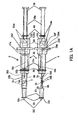
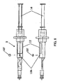
- FIG. 1A is a top view and a side view of an insertion device for an intraocular lens that is an embodiment of the present invention
- FIG. 1B is a sectional view of a lens housing portion in a main body with a nozzle of the embodiment
- FIG. 1C is a sectional view of a nozzle portion in the main body with a nozzle of the embodiment
- FIG. 2 is a top view and a side view before assembly of the main body with a nozzle and a pushing shaft of the embodiment;
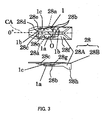
- FIG. 3 is a top view and a side view of a lens holding member of the embodiment
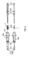
- FIG. 4 is a top view and a side view showing an assembling procedure of the insertion device of the embodiment
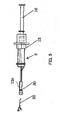
- FIG. 5 is a side view for illustrating a liquid introduction method into the insertion device of the embodiment
- FIG. 6 is a perspective view for illustrating the liquid introduction method into the insertion device of the embodiment.
- FIG. 7 is a top view and a side view for illustrating the liquid introduction method into the insertion device of the embodiment
- FIG. 8 is a top view and a side view for illustrating the liquid introduction method into the insertion device of the embodiment
- FIG. 9 is a top view and a side view for illustrating the liquid introduction method into the insertion device of the embodiment.
- FIG. 10 is a top view and a side view for illustrating a storage method of the insertion device of the embodiment
- FIG. 11 shows an incision formed in an eyeball
- FIG. 12 is a top view and a side view of an insertion device of a comparative example for the embodiment:
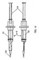
- FIG. 13 is a top view and a side view showing a state in which a cover ring is removed from the insertion device of the embodiment
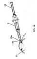
- FIG. 14 is a sectional view showing a state of an eyeball when a lens is inserted using the insertion device in FIG. 13;
- FIG. 15 is a sectional view showing a state of an eyeball when a lens is inserted using the insertion device of the embodiment
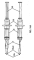
- FIG. 16A is a top view and a side view of an insertion device of a comparative example for the embodiment
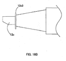
- FIG. 16B is a side view of a nozzle portion of an insertion device of an embodiment (a modified example).
- FIG. 17A is a sectional view of a nozzle portion of an insertion device of an embodiment (a modified example).
- FIG. 17B is a sectional view of a nozzle portion of an insertion device of an embodiment (a modified example).
- FIG. 18 is a perspective view of a nozzle portion of an insertion device of an embodiment (a modified example).
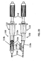
- FIG. 19 is a side view and a bottom view of a nozzle portion of an insertion device of an embodiment (a modified example).
- FIG. 20 is a top view and a side view of a conventional type insertion device
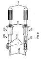
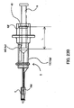
- FIG. 21 is a side view and a top view of an insertion device (of a conventional type) of an embodiment
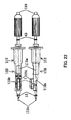
- FIG. 22 is a top view and a side view of an insertion device (of a conventional type) of an embodiment
- FIG. 23A is a side view showing an assembly completion state of the insertion device of the embodiment.
- FIG. 23B is a side view showing a lens pushing state of the insertion device of the embodiment.
- FIG. 1A shows an insertion device for an intraocular lens (hereinafter simply referred to as a lens) that is an embodiment of the present invention.
- the upperside in FIG. 1A shows a top view thereof and the lowerside shows a side view thereof.
- FIG. 2 shows a state before a pushing shaft is assembled to a main body of the insertion device.
- the upperside in FIG. 2 shows a top view thereof and the lowerside shows a side view thereof.
- a nozzle side is referred to as a front end side, a front or a front end direction, and a side opposite to the nozzle side is referred to as a rear end side, a rear or a rear end direction.
- a direction extending toward the front end side and the rear end side is referred to as an axial direction, and a direction perpendicular to the axial direction is referred to as a vertical direction, a lateral (right-and-left) direction, or a radial direction.
- a central axis an axis parallel to the axial direction and passing through an inner space of a main body with a nozzle or the center of a lens
- a direction around the central axis is referred to as a circumferential direction.
- An insertion device 2 is basically constituted by a main body with a nozzle (hereinafter simply referred to as a main body) 12, and a pushing shaft 16.
- the main body 12 Includes an outer cylindrical portion 12a as a hand-held portion having an outer diameter suitable for holding the insertion device 2 by hand, a lens housing portion 12b that is provided on the side closer to the front end than the outer cylindrical portion 12a and houses a lens holding member 28 described later, and a nozzle portion 12c as an insertion cylindrical portion provided on the side closer to the front end than the lens housing portion 12b.
- the main body 12 is an integrally formed component (member).
- a flange portion 12d is formed as a portion supported by hand when pushing the pushing shaft 16.
- the main body 12 has a hollow shape, and the lens holding member 28 and the pushing shaft 16 are inserted through a rear end opening 12i thereof.
- the outer cylindrical portion 12a has a first inner peripheral surface 12g having a cylindrical shape from the front end thereof to a position between the flange portion 12d and the rear end of the outer cylindrical portion 12a.
- a second inner peripheral surface 12m having a cylindrical shape and a slightly smaller inner diameter than the first inner peripheral surface 12g is formed.
- a conical surface 12f is formed which has an increasing inner diameter toward the rear end.
- a third inner peripheral surface having a cylindrical shape and a larger inner diameter than the first inner peripheral surface 12g is formed up to the rear end opening 121.
- the nozzle portion 12c has decreasing inner and outer diameters toward the front end, and a portion from a front end opening 12j to a predetermined length is formed to be the thinnest portion in the nozzle portion 12c as a portion to be inserted into an eye through an incision formed in an eyeball.
- a cover ring (an 0-ring) 13 made of an elastic member such as rubber is mounted on an outer periphery of the rear end of the insertion portion.
- a cover ring (an 0-ring) 13 made of an elastic member such as rubber is mounted on an outer periphery of the rear end of the insertion portion.
- a cover ring 13 made of an elastic member such as rubber is mounted on an outer periphery of the rear end of the insertion portion.
- a step 12c1 is formed having a larger outer diameter than the insertion portion for preventing rearward movement of the cover ring 13. The function of the cover ring 13 will be described later.
- the lens housing portion 12b basically has a section of a hollow flat plate shape having a vertical dimension smaller than a lateral dimension in axial view.
- a rear portion in a lower surface of the lens housing portion 12b near a boundary with the outer cylindrical portion 12a has a semi-conical shape having an increasing diameter toward the rear for reinforcement.
- the lens housing portion 12b is inserted through the rear end opening 12i, and thus a connection between the outer cylindrical portion 12a and an inner surface of the lens housing portion 12b is tapered to provide a guide configuration and facilitate insertion when the holding member 28 is inserted.
- the lens housing portion 12b can receive the insertion of the lens holding member 28 from the rear end thereof, and has an inner surface shape that can stably hold the inserted lens holding member 28.
- peripheral walls 12b1 and 12c4 from the lens housing portion 12b to the nozzle portion 12c are formed as integral walls without an opening and a gap.
- four side (upper, lower, right and left) walls surrounding an inner space are circumferentially connected, and integrally formed without an opening such as a hole and a dividable portion or an openable and closable portion in which a gap is created in an assembled portion.
- the main body 12 is produced as an integrally formed component (member) so that at least the peripheral walls 12b1 and 12c4 from the lens housing portion 12b to the nozzle portion 12c have no opening or gap.
- an alternative embodiment of the present invention is not limited to this case.
- components divided into two upper and lower portions from the front end to the rear end may be joined by thermal welding or bonding and integrated to constitute the main body 12, and the main body 12 is thereby made as an integral component (member) without a gap at least in peripheral walls of the lens housing portion 12b and nozzle portion 12c after completion of the main body 12 (before insertion of the lens holding member 28).
- the lens housing portion 12b, the nozzle portion 12c and the outer cylindrical portion 12a that are formed in a divided manner are joined by thermal welding or bonding, and the main body 12 is thereby made as an integral component without a gap at least in peripheral walls from the lens housing portion 12b to the nozzle portion 12c after completion of the main body 12 (before insertion of the lens holding member 28).
- a small hole 12h is formed in a peripheral wall near the front end of the outer cylindrical portion 12a.
- This hole 12h is naturally formed for placing a member that supports a die for forming the inner surface of the main body 12 in production of the main body 12, that is, when the main body 12 is integrally formed of resin.
- an O-ring 32 made of an elastic member such as rubber is mounted to the outer periphery of the outer cylindrical portion 12a.
- the main body 12 has no opening other than the rear end opening 12i in the outer cylindrical portion 12a and the front end opening 12j in the nozzle portion 12c.
- the rear end opening 12i is covered with a seal cap 14 provided on the pushing shaft 16 without a gap
- the front end opening 12j is covered with a cap 34 described later without a gap, thereby allowing a sealed space to be formed in the main body 12 that can house a liquid such as a viscoelastic material or physiologic saline without leakage, and store the liquid with the lens 1.
- a mounting surface for the O-ring 32 on the outer peripheral surface of the outer cylindrical portion 12a has a diameter smaller than those on the sides closer to the front and rear ends. This prevents axial movement of the O-ring 32 on the outer cylindrical portion 12a.
- the O-ring 32 is provided on a position often touched by hand of an operator holding the insertion device 2.
- the O-ring 32 has the function of covering the hole 12h as well as the function of preventing slip of the hand holding the insertion device 2. If not covering the hole 12h does not directly influence the flow of the liquid, covering of the hole 12h is not necessarily required.
- the lens holding member 28 includes a first holding member 28A that supports the lens 1 from below, and a second holding member 28B that retains from above the lens 1 in combination with the first holding member 28A.
- the lens 1 has a circular shape in top view, and includes an optical portion 1a having the function of a lens and support portions 1b extending from the front end and the rear end of the optical portion 1a.
- the support portion 1b is a wire-like portion that elastically supports the optical portion 1a in the eye after the lens 1 is inserted into the eye.
- a ring-shaped marginal (peripheral) portion 1c having parallel upper and lower surfaces is formed around the optical portion 1a.
- the marginal portion 1c is hereinafter referred to as the lens marginal portion 1c.
- the first holding member 28A is formed laterally symmetrically with respect to the central axis CA passing through the center O of the optical portion 1a of the lens 1 except part thereof.
- Support surfaces 28a are formed on the right and left in the lower portion of the first holding member 28A.
- the support surfaces 28a are formed as inclined surfaces whose inner portion is lower than its outer portion in the lateral direction.
- a position in the front end direction from the center O of the optical portion 1a in the lens marginal portion 1c is a 0° position.
- the right and left support surfaces 28a contact arcuate regions between positions retracted by a circumferential angle of 60° to both circumferential sides (60° positions, other positions are hereinafter referred to as the same) from the 0° position in the lens marginal portion 1c, and 90° positions retracted by a circumferential angle of 90°, and support the arcuate regions from below.
- support protrusions 28b are formed which support arcuate regions between 135° positions to 165° positions which are regions closer to the rear than the arcuate regions supported by the support surfaces 28a in the lens marginal portion 1c.
- a space through which the pushing shaft 16 (a pushing shaft portion 16c) passes is provided between the support protrusions 28b. Since the space has only a 30° angle range, it may be considered that the support protrusions 28b support an arcuate region of a 90° angle range around a 180° position in the lens marginal portion 1c.
- the first lens support member 28A supports the lens marginal portion 1c at three points at 120° intervals including the right and left 60° positions and the 180° position.
- Each of the support protrusions 28b has a horizontal surface on which the lens marginal portion 1c is placed and a vertical surface that contacts or is brought close to an outer peripheral end surface of the lens marginal portion 1c on the rear side of the horizontal surface, supports the lens marginal portion 1c from below, and prevents rearward movement of the lens 1.
- a vertical surface 28e is formed that contacts or is brought close to the 60° position in the outer peripheral end surface of the lens marginal portion 1c.
- the vertical surface 28e prevents movement of the optical portion 1a in the front end direction in a state before pushing out the lens 1.
- an arm 28c is formed extending from one side to the other side in the lateral direction (from the lower side to the upper side in the top view in FIG. 3), and at the tip of the arm 28c, a protrusion 28d that supports from below the front side support portion 1b is formed to extend in the front end direction.
- an inclined surface 28f that supports from below the rear side support portion 1b is formed so that its portion closer to the rear end is placed in a higher position.
- the second holding member 28B is placed above the first holding member 28A.
- the first and second holding members 28A and 28B are inserted into the lens housing portion 12b while holding the lens 1, and held between a ceiling surface and a bottom surface of the lens housing portion 12b without displacement.
- the second holding member 28B is formed laterally symmetrically with respect to the central axis CA, though not shown.
- retaining protrusions 28g are formed that contact or are brought close to arcuate regions from the 90° positions to 120° positions and arcuate regions from the 135° positions to the 165° positions on the right and left in the lens marginal portion 1c.
- a space through which the pushing shaft 16 (the pushing shaft portion 16c) passes is provided between the right and left retaining protrusions 28g with the 180° position therebetween.
- a portion on the front side of the retaining protrusion 28g retains from above an arcuate region closer to the rear than the arcuate region that contacts the support surface 28a provided in the first holding member 28A in the lens marginal portion 1c, and a portion on the rear side of the retaining protrusion 28g retains from above the arcuate region supported from below by the support protrusion 28b provided in the first holding member 28A in the lens marginal portion 1c.
- the second holding member 28B is assembled to the upper side of the first holding member 28A, and thus the arcuate regions from the 60° positions to the 90° positions in the lens marginal portion 1c are supported from below by the support surfaces 28a of the first holding member 28A, and the arcuate regions from the 90° positions to the 120° positions are retained from above by the front side portions of the retaining protrusions 28g in the second holding member 28B.
- the arcuate regions from the 135° positions to the 165° positions are vertically held by the horizontal surfaces of the support protrusions 28b provided in the first holding member 28A and the rear side portions of the retaining protrusions 28g provided in the second holding member 28B therebetween.
- the state in which a stress is not substantially applied denotes a state in which no stress is applied to the optical portion at all as well as a state in which a minute stress is applied so that a deformation influencing the optical function of the optical portion 1a after insertion of the lens 1 into the eye does not occur even if the lens 1 is held and stored for a long time.
- the state denotes a state in which a stress or a deformation influencing the optical function of the optical portion 1a does not occur.
- the vertical surfaces 28e that contact the 60° positions in the outer peripheral end surface of the lens marginal portion 1c and the vertical surfaces of the support protrusions 28b that contact the regions from the 135° positions to the 165° positions prevent displacement of the lens 1 in the front end direction and the rear end direction. Further, the front end side of the lens marginal portion 1c is opened by 120°, by providing the right and left vertical surfaces 28e in the 60° positions. This allows the lens 1 to be smoothly moved from the lens holding member 28 in the front end direction in pushing out the lens 1.
- inclined portions are formed that extend in parallel with the inclined surface 28f in the first holding member 28A and hold the rear side support portion 1b together with the inclined surface 28f.
- the vertical surfaces 28e in the first holding member 28A are formed such that one of them extends in the front end direction along the outer edge of the front side support portion 1b and the other extends in the same shape as the one.
- the contact of the one of the vertical surfaces 28e with the front side support portion 1b and the holding of the rear side support portion 1b between the inclined surface 28f and the inclined portions of the retaining protrusions 28g prevent rotation of the lens 1.
- the configuration of the lens holding member is not limited to the above case, and any lens holding member may be allowed that can hold a lens in a state in which a stress is not substantially applied to an optical portion.
- the lens is not limited to one having an optical portion and a wire-like support portion, but may have an optical portion and a support portion having a flat plate shape.
- FIG. 20 shows a conventional type insertion device.
- the upperside in FIG. 20 shows a top view thereof and the lowerside shows a side view thereof.
- a main body 112 of the insertion device 102 is constituted by a plurality of components including an outer cylinder 112a, a lens holding member 112b assembled to the front end of the outer cylinder 112a, and a nozzle 112c assembled to the lens holding member 112b so as to extend from a lower surface of the lens holding member 112b to the front end.
- An opening 112h is formed in an upper surface of the lens holding member 112b, and a lens 1 is set in the lens holding member 112b through the opening 112h.
- a cover member 124 is mounted to the lens holding member 112b so as to cover the opening 112h.
- gaps are created at assembled portions of the plurality of components.
- the opening 112h through which the lens 1 is set is formed, and a gap leading to the outside from the opening 112h is created even if the opening 112h is covered with the cover member 124.
- the liquid when a liquid such as a viscoelastic material or physiologic saline is introduced into the main body 112, the liquid leaks from the gap.
- physiologic saline having a lower viscosity than the viscoelastic material leaks immediately after being introduced, and it is difficult to maintain the viscoelastic material in an amount required for an operation in the main body 112.
- the amount of leakage of the viscoelastic material is small because of its viscosity, the leakage may make the insertion device 102 slippery and is unpreferable.
- the pushing shaft 16 has a D-cut shaft portion 16a, a cylindrical portion 16b, and a pushing shaft portion 16c in order from the rear end side thereof.
- the D-cut shaft portion 16a has a so-called D-cut shape having a section in axial view of a non-rotationally symmetric shape with a circular upper portion out to be flat.
- an O-ring (a second elastic member) 43 made of an elastic member such as rubber is mounted axially movably relative to the D-cut shaft portion 16a.
- the cylindrical portion 16b has the same or a smaller outer diameter as or than a cylindrical portion of the D-cut shaft portion 16a, and the seal cap (a first elastic member) 14 made of an elastic member such as rubber is mounted to the outer periphery of the cylindrical portion 16b.
- the seal cap 14 has a ring portion 14a mounted on the cylindrical portion 16b, and a conical portion 14b having a decreasing diameter from the front end of the ring portion 14a toward the front end. A hole through which the pushing shaft portion 16c passes is formed in the front end of the conical portion 14b.
- the pushing shaft portion 16c has a small outer diameter that can pass through an inner passage of the nozzle portion 12c, and has, at the front end thereof, a lens grip portion 16d vertically bifurcated.
- the lens grip portion 16d vertically holds the rear end of the optical portion 1a of the lens 1 held by the lens holding member 28 in the lens housing portion 12b. This allows the lens 1 to be reliably pushed by the pushing shaft 16 in the front end direction.
- a rubber ring is mounted on an outer periphery of a pushing shaft, and the rubber ring slides relative to an inner surface of the main body with movement of the pushing shaft.
- the rubber ring is intended for providing proper sliding feeling (operation resistance) to an operation of the pushing shaft, and has no sealing function of preventing leakage of a liquid housed in the main body.
- the seal cap 14 of the embodiment mainly has the sealing function, and is brought into press contact with the inner peripheral surface of the main body 12 by a press-contact force for achieving the sealing function, thereby also providing sliding feeling.
- an axial width of the ring portion 14a of the seal cap 14 is set to 2 mm or more, and further, on the front end side of the ring portion 14a, the conical portion 14b is provided for preventing the liquid from leaking from the gap between the ring portion 14a and the cylindrical portion 16b of the pushing shaft 16. Further, in the embodiment, in a state before pushing of the pushing shaft 16 (an assembly completion state or a storage state) in FIG.
- the inner diameter of the second inner peripheral surface 12m with which the ring portion 14a of the seal cap 14 is brought into press contact in the inner peripheral surface of the main body 12 is set to be smaller than the inner diameter of the first inner peripheral surface 12g formed on the side closer to the front end than the second inner peripheral surface 12m.
- the inner diameter of the second inner peripheral surface 12m is set to be small to increase the press-contact force with the ring portion 14a of the seal cap 14, thereby increasing the sealing function.
- the insertion device 2 can be stored so that the liquid introduced into the main body 12 does not leak.
- the inner peripheral surfaces 12g and 12m of the main body are preferably circular.
- the outer peripheral surface of the ring portion 14a of the seal cap 14 may be a simple cylindrical surface, but in order to increase the sealing function, the outer peripheral surface may have a ring shape with a semicircular section or have a plurality of ring shapes in the axial direction.
- the lens grip portion 16d that holds the upper and lower surfaces of the optical portion 1a of the lens 1 is provided in the front end of the pushing shaft 16, and when the pushing shaft 16 is pushed in a state in which the pushing shaft 16 is rotated with respect to the main body 12, the lens grip portion 16d cannot properly push the optical portion 1a.
- the rotation of the pushing shaft 16 with respect to the main body 12 needs to be prevented.
- the pushing shaft 16 is removed from the main body 12 before pushing or after the start of the pushing, reinsertion thereafter of the pushing shaft 16 into the main body 12 is not always properly performed, and thus the removal needs to be prevented.
- the function required for the pushing shaft 16 of the insertion device 2 is different from a simple sealing function required for a general syringe.
- the inner diameter of the second inner peripheral surface 12m is set to be small, and using an increase thereby in the press-contact force between the ring portion 14a of the seal cap 14 and the second inner peripheral surface 12m, that is, a friction force, the configuration is achieved in which the pushing shaft 16 is hardly rotated with respect to the main body 12 or removed from the main body 12.
- the rotation of the pushing shaft 16 with respect to the main body 12 or the removal thereof from the main body 12 is restricted using friction caused by press contact between the seal cap 14 and the main body 12, but the rotation or the removal of the pushing shaft may be restricted by other methods.
- the main body 12 has an inner peripheral shape similar to an outer peripheral shape of the D-cut shaft portion 16a of the pushing shaft 16, and flat surface portions thereof contact each other to prevent rotation of the pushing shaft 16 with respect to the main body 12.
- a step formed between the D-cut shaft portion 16a and the cylindrical portion 16b (the seal cap 1.4) may contact a contact surface formed in the main body 12 to prevent removal of the pushing shaft 16 from the main body 12.
- FIG. 21 shows the configuration in which a double seal ring 44 corresponding to the seal cap 14 in the embodiment is provided in the pushing shaft 116, and the inner diameter of a portion (seal portion) with which the double seal ring 44 is brought into press contact in the inner peripheral surface of the rear end side portion of the main body 112 is smaller than that of an inner peripheral surface of a portion closer to the front end than the above seal portion.
- FIG. 4 An assembling procedure of the insertion device 2 thus configured will be described with reference to FIG. 4 (the upperside shows a top view and the lowerside shows a side view).
- the lens 1 is held by the lens holding member 28.
- the O-ring 32 and the cover ring 13 are mounted to the outer peripheries of the outer cylindrical portion 12a and the nozzle portion 12c, respectively, of the main body 12.
- the hole 12h is used for introducing a liquid into the main body 12 after the assembly, it is recommended to displace the O-ring 32 to a position where it does not cover the hole 12h.
- the lens holding member 28 is inserted from the rear into the lens housing portion 12b through the rear end opening 12i.
- the lens holding member 28 inserted into the lens housing portion 12b is held by contact of the outer surface thereof with the inner surface of the lens housing portion 12b substantially without circumferential and axial backlash.
- the pushing shaft 16 to which the O-ring 43 and the seal cap 14 are mounted is inserted into the main body 12 through the rear end opening 12i.
- the pushing shaft 16 is inserted until the lens grip portion 16d reaches the immediate rear of the lens 1 in the lens housing portion 12b.
- the outer peripheral surface of the ring portion 14a of the seal cap 14 is brought into press contact with the second inner peripheral surface 12m of the outer cylindrical portion 12a to perform the sealing function and the rotation and removal preventing function described above.
- the O-ring 43 is also caused to contact the conical surface 12f formed in the inner periphery of the outer cylindrical portion 12a.
- the function of the O-ring 43 will be described later.
- a liquid such as a viscoelastic material such as sodium hyaluronate or physiologic saline (including one in which drug is dissolved) as described later.
- a liquid introduction method will be described below.
- a liquid to be introduced includes hydrophilic (water-soluble) polymer liquid besides sodium hyaluronate or physiologic saline.
- synthetic polymer includes polyethylene glycol (PEG), polypropylene glycol (PPG), sodium polyacrylate (PAA), polyacrylamide (PAAm), sodium polystyrene sulfonate (PSSNa), polyvinylpyrrolidone (PVP), polyvinyl alcohol (PVA), polyethyleneimine (PEI), carboxymethylcellulose (CMC), dextran sodium sulfate, hydroxyethyl starch (HEPES), and polyphosphoric acid.
- PEG polyethylene glycol
- PPG polypropylene glycol
- PAA sodium polyacrylate
- PAAm polyacrylamide
- PSSNa sodium polystyrene sulfonate
- PVP polyvinylpyrrolidone
- PVA polyvinyl alcohol
- PEI polyethyleneimine
- CMC carboxymethylcellulose
- HPES dextran sodium sulfate
- HPES hydroxyethyl starch
- Natural polymer includes hyaluronate and/or sodium hyaluronate (HA), sodium alginate, dextran, dextrin, heparin, chitosan, and sodium chondroitin sulfate as polysaccharide, and polypeptide and polynucleic acid as other than polysaccharide.
- HA hyaluronate and/or sodium hyaluronate
- polysaccharide is preferably used in view of biocompatibility or the diversity of molecular weight obtained.
- FIG. 5 shows a first liquid introduction method.
- the liquid in a syringe 35 is introduced through an injection needle inserted into the front end opening 12j of the nozzle portion 12c.
- the O-ring 32 is placed to cover the hole 12h formed in the main body 12.
- the liquid introduced into the main body 12 hardly leaks even if the front end opening 12j is directed downward because the main body 12 has no opening leading to the outside other than the front end opening 12j. This also applies to liquid introduction methods described below.
- FIG. 6 shows a second liquid introduction method.
- the liquid is placed in a container 36 such as a sterile beaker, and the pushing shaft 16 is drawn rearward in a state in which the nozzle portion 12c is inserted in the liquid.
- the main body 12 is sealed except the front end opening 12j, thereby allowing the liquid to be introduced into the main body 12 similarly to the syringe.
- the lens grip portion 16d of the pushing shaft 16 needs to be inserted until it reaches the immediate rear of the lens 1 in the lens housing portion 12, and can reliably push the lens optical portion according to the position relationship thereof.
- the configuration is adopted in which two pushing shafts are provided, a hole is formed in one pushing shaft with a seal cap 14 having no lens grip portion 16d, and the other pushing shaft 16 having a lens grip portion 16d can be assembled in the hole. Then, the pushing shaft having the seal cap 14 is drawn rearward in a state in which the pushing shaft 16 having the lens grip portion 16d is fixed in the position. This allows the liquid to be introduced similarly to the syringe in a state in which the lens grip portion 16d of the pushing shaft 16 is fixed in the position on the immediate rear of the lens housing portion 12.
- FIG. 7 shows a third liquid introduction method.
- the O-ring 32 is displaced from the hole 12h formed in the main body 12, the needle of the syringe 35 or a liquid supply device is inserted into the hole 12h to introduce the liquid into the main body 12. Then, the O-ring 32 is moved so as to cover the hole 12h.
- the outer peripheral surface having the hole 12h is tapered to function as a guide in insertion so as to facilitate insertion of the front end of the needle or the liquid supply device, which further increases operability.
- FIG. 8 shows a fourth liquid introduction method.
- a plug (a lid) 33 made of an elastic member fitted in the hole 12h is used in place of the O-ring 32.
- the needle of the syringe 35 is inserted into the plug 33 to introduce the liquid in the syringe into the main body 12.
- the plug 33 can prevent leakage of the liquid because a hole after removal of the needle is closed by elasticity thereof.
- it is recommended to devise the shape of the plug 33 it is recommended to devise the shape of the plug 33.
- a portion of the plug 33 fitted in the hole 12h preferably has an increasing thickness toward the bottom.
- the plug 33 may be bonded to the main body 12.
- FIG. 9 shows a fifth liquid introduction method.
- the needle of the syringe 35 or the liquid supply device is inserted into the hole 12h to introduce the liquid into the main body 12.
- a lid (a plug) 33' is mounted to the main body 12 so as to cover the hole 12h to prevent the liquid from leaking from the hole 12h.
- a portion of the lid 33' fitted in the hole 12h preferably has an increasing thickness toward the bottom.
- the lid 33' may be bonded to the main body 12.
- the liquid can be easily introduced into the main body 12 immediately before an operation or before factory shipment of the insertion device.
- the nozzle portion 12c is preferably covered with the cap 34 in FIG. 10 in order to prevent leakage of the liquid outside during the shipment, transportation and storage.
- the cap 34 has no opening in the front end and the peripheral wall portion, and has an opening in the rear end.
- a seal ring 27 made of an elastic member is mounted to the inside of the rear end.
- the cap 34 is mounted so that the seal ring 27 is brought into tight contact with the outer peripheral surface of the nozzle portion 12c (or the lens housing portion 12b) to form a closed space around the nozzle portion 12c.
- the liquid does not leak outside. This also prevents vaporization of the liquid and damage to the nozzle portion 12c.
- the lens 1 as well as the liquid can be held in the insertion device 2 and stored for a long time.
- the cap 34 is removed if mounted, and the front end (a portion to be inserted into an eye) of the nozzle portion 12c is inserted into the eye through an incision formed in an eyeball. Then, the pushing shaft 16 is pushed into the main body 12.
- the liquid in the main body 12 starts to be introduced into the eye through the front end opening 12j of the nozzle portion 12c, and the lens 1 with the optical portion 1a held by the lens grip portion 16d starts to be moved from on the lens holding member 28 in the front end direction.
- the lens 1 is folded and deformed into a small shape with movement in the nozzle portion 12c, and pushed into the eye through the front end opening 12j.
- the liquid is introduced into the eye from the nozzle portion 12c to increase ocular tension and inflate the anterior chamber, thereby forming an insertion space for the lens 1.
- the incision 15a has a larger area than the nozzle portion 12c, thereby creating a gap (a region outside the nozzle portion 12c) 20 between the periphery of the incision 15a and the outer peripheral surface of the nozzle portion 12c.
- the liquid once introduced into the eye leaks from the gap 20, and in particular, when the amount of liquid introduced into the main body 12 is relatively small (for example, about 0.5 to 2.5 ml), the ocular tension cannot be increased and the anterior chamber cannot be sufficiently inflated.
- the cover ring 13 provided near the front end of the nozzle portion 12c is pressed against the eyeball 15 to cover the gap 20 in the incision 15a.
- the cover ring 13 may completely or partly cover the gap 20. This can restrict (prevent or reduce the amount of) the flow of the liquid from the gap 20, and even if the amount of the liquid introduced into the main body 12 is relatively small, the ocular tension can be reliably increased to sufficiently inflate the anterior chamber.
- the insertion device 2 is displaced rearward so as to separate the cover ring 13 from the eyeball 15, and the liquid flows out of the gap 20 of original size, thereby reducing the ocular tension.
- the lens 1 can be inserted into the eye and also the ocular tension can be controlled simply by an operation on hand of the operator.
- the cover ring 13 as a separate member from the nozzle portion 12c is used for covering the gap 20 in the incision 15a in the eyeball 15, but a ring-shaped portion having the same function as the cover ring 13 may be formed integrally with the nozzle portion 12c.
- Experiment 2 An experiment was conducted using an insertion device 2 in which a liquid of 25 ml was previously introduced into a main body 12 as shown in FIG. 13. In this experiment, a nozzle portion 12c did not have a cover ring 13 or a configuration corresponding thereto. In this case, even if a pushing shaft 16 was pushed to introduce most of the liquid in the main body 12 into the eye, ocular tension hardly increased from ocular tension when an incision was formed, and the posterior capsule of the crystalline lens did not move toward the vitreous body. The reason that the ocular tension did not increase was studied and found. It was because the incision was linearly formed by a knife, and the three-dimensional nozzle portion 12c was inserted into the incision to form a gap 20 in FIG. 11, and a liquid L leaked from the gap 20 as shown in FIG. 14.
- Experiment 3 A cover ring 13 was mounted to the nozzle portion 12c of the insertion device 2 used in Experiment 2, and the cover ring 13 was brought into tight contact with a portion near the incision 15a in the eyeball 15 as shown in FIG. 15, and an experiment similar to Experiment 2 was conducted. In this case, ocular tension increased and the posterior capsule of the crystalline lens moved toward the vitreous body. It was confirmed that this was because a gap 20 is created outside the nozzle portion 12c in the incision 15a, but the cover ring 13 is brought into tight contact with around the incision 15a in the eyeball 15, and thus even if the liquid flows out of the gap 20, a seal by the cover ring 13 prevents the liquid from leaking outside.
- the cover ring 13 has a circular section, and thus the cover ring 13 is brought into ring-shaped line contact around the incision 15a in the eyeball 15.
- a sealing effect was able to be obtained more easily and reliably than the case of a seal by surface contact.
- a step 12cl was provided in the nozzle portion 12c to prevent the cover ring 13 from moving rearward on the nozzle portion 12c. Also, a tilt of the cover ring 13 on the nozzle portion 12c was allowed to stably maintain a tight contact state of the cover ring 13 on the eyeball 15.
- a ring-shaped portion 12c2 having substantially the same shape as the cover ring 13 was formed integrally with the nozzle portion 12c, and an experiment similar to Experiments 2 and 3 was conducted.
- the ring-shaped portion 12c2 had little flexibility.
- the ring-shaped portion 12c2 was able to be partly brought into tight contact with the eyeball 15, but other portions was not able to be brought into tight contact with the eyeball 15, and the liquid leaked outside from a gap between the eyeball 15 and the ring-shaped portion 12c2.
- ocular tension hardly increased.
- a ring-shaped portion (a cover-ring-shaped portion) 12c3 is formed to have a thickness of about 0.3 mm and have flexibility, and thus the entire circumference of the cover ring-shaped portion 12c3 can be brought Into tight contact with the eyeball 15, and a sealing effect equal to the seal ring 13 can be obtained.
- FIGS. 17A and 17B show the shape of a section of a nozzle portion 12c of an insertion device used in this experiment. As shown in FIG. 11, when the nozzle portion 12c having a circular section or an oval section is inserted into the incision 15a, the incision 15a is opened to a substantially rhombic shape. Then, gaps 20 each having a substantially triangular shape are formed between the nozzle portion 12c and the edges of the incision 15a.
- nozzle portions 12c' and 12c" having protruding incision covering shapes 12c4 and 12c5 that can substantially fill the gaps 20 were formed, and an experiment similar to Experiments 2 to 4 was conducted.
- the gaps created between the nozzle portions 12c' and 12c" and the edges of the incision 15a were reduced in size or eliminated, and thus the leakage of the liquid from the eyeball 15 was reduced or prevented to increase the ocular tension.
- the nozzle portion itself is formed to have the shape that can fill the gaps 20 to obtain a sealing effect equal to the case where the cover ring 1,3 or the cover-ring-shaped portion 12c3 is provided in the nozzle portion 12c.
- Experiment 6 As in Experiments 3 and 4, providing the cover ring 13 or the cover-ring-shaped portion 12c3 in the nozzle portion 12c can increase ocular tension. It is more preferable to provide the configuration for adjusting ocular tension to proper one when the ocular tension becomes too high to the contrary.
- an opening such as a hole 37 or a slit 38 was provided on the front end side of the nozzle portion 12c from the cover ring 13 or the cover-ring-shaped portion 12c3. Also, an inclined portion 39 was formed in the front end of the nozzle portion 12c.
- the insertion device 2 When the ocular tension becomes too high, the insertion device 2 is slightly drawn from the eyeball so that part of the hole 37, the slit 38 or the inclined portion 39 is exposed to the outside of the eye, and thus a liquid flowing from the main body 12 to the front end opening 12i of the nozzle portion 12c or a liquid in the eye is ejected to the outside of the eye through the hole 37 or the like. This facilitates adjustment of the ocular tension.
- the hole 37 or the like may be placed in the eye to bring the cover ring 13 or the cover-ring-shaped portion 12c3 into tight contact with the eyeball.
- FIG. 19 the upperside is a side view and the lowerside is a bottom view.
- an inclined portion 41 was first provided on the lower side of the front end of the nozzle portion 12c.
- a peripheral wall from the front end of the inclined portion 41 (the front end of the nozzle portion 12c) to the rear end of the inclined portion 41 is hereinafter referred to as a front end peripheral wall T.
- the front end peripheral wall T was formed over the entire circumference to be a tapered surface 40 inclined by an angle of 10° or more in a tapering direction with respect to a peripheral wall closer to the front end than the peripheral wall T. This facilitated insertion of the nozzle portion 12c into an incision in an eyeball with low ocular tension.
- the taper When the tapered surface 40 having an angle of 10° or more is formed from a position closer to the rear than the rear end of the inclined portion 41, the taper excessively reduces a space in the nozzle portion to excessively increase friction resistance when the lens 1 passes through the space in the nozzle portion.
- the tapered surface 40 is formed on the front end side from the rear end of the inclined portion 41 to prevent an increase in friction resistance when the lens 1 passes through the inside of the nozzle portion 12c. Further, when the lens 1 passes the rear end of the inclined portion 41, deformation of the lens 1 is released and a stress generated in the lens 1 by the deformation is released, thereby reducing friction resistance. This facilitated insertion of the nozzle portion 12c into the incision in the eyeball with low ocular tension, and achieved the nozzle portion 12c with a light load on the lens 1.
- Experiment 8 The configuration in which the cover ring 13, or the cover-ring-shaped portion 12c3 described in Experiments 3 and 4, or the protruding incision covering shapes 12c4 and 12c5 is provided in the nozzle portion may be applied not only to the insertion device of the embodiment but to the conventional type insertion device as shown in FIG. 20.
- FIG. 22 shows an insertion device in FIG. 20 provided with a cover ring 13 in a nozzle portion.
- a viscoelastic material was used as a lubricant.
- the cover ring 13 was provided in the nozzle portion 112c of the insertion device 102 to bring the cover ring 13 into tight contact with the eyeball 15 similarly to Experiments 3 and 4. Thus, the amount of flow of the viscoelastic material in the eye from the incision was able to be reduced.
- the O-ring 43 described above is mounted on the pushing shaft 116 of the insertion device 102 in FIG. 22. In this manner, the 0-ring 43 may be used in the conventional type insertion device 102 in FIG. 20.
- the function of the O-ring 43 will be described with reference to FIGS. 23A and 23B.
- the O-ring (the second elastic member) 43 that contacts the conical surface 12f formed in the inner periphery of the rear end of the outer cylindrical portion 12a and the seal cap 14 (the ring portion 14a: the first elastic member) secured to the pushing shaft 16 are close to each other.
- the pushing shaft 16 is supported by two points: the ring portion 14a of the seal cap 14 and the O-ring 43 with respect to the main body 12, and thus as compared with the case where the pushing shaft 16 is supported only by the ring portion 14a of the seal cap 14, vertical and lateral displacement of the pushing shaft 16 relative to the main body 12 can be suppressed.
- the 0-ring 43 may be mounted on the pushing shaft 16 or may be secured to the inner periphery of the main body 12.
- a plurality of members corresponding to the O-ring 43 may be provided rather than one.
- a plurality of O-rings 43 are placed axially adjacent to each other, and brought into press contact with the inner peripheral surface of the main body 12 and the outer peripheral surface of the pushing shaft 16 to provide the sealing function, thus leakage of the liquid from the rear end opening 12i of the main body 12 can be more reliably prevented in combination with the sealing function of the seal cap 14.
- An elastic member corresponding to the O-ring 43 may be secured on the front end side of the main body from the seal cap on the pushing shaft so that the distance between the plurality of elastic members corresponding to the O-ring and the seal cap is reduced from a maximum state to a moderate state with the movement of the pushing shaft in the front end direction. Also in this case, as compared with the case where the elastic member corresponding to the seal cap only is provided, vertical and lateral displacement of the pushing shaft relative to the main body can be minimized, and the lens can be properly pushed out.
- the peripheral wall from the lens housing portion to the insertion cylindrical portion is formed without an opening or a gap, thereby reliably preventing the liquid inside from leaking outside. Further, the lens holding member can be inserted into the lens housing portion from the rear, and thus the lens can be easily set into the lens housing portion.
- the lens holding member placed in the lens housing portion can reliably hold the lens in a predetermined shape, and thus the lens is not moved or deformed by the flow of the liquid in the main body, and the insertion device housing the lens can be properly stored. In this case, the need for introducing the liquid into the insertion device immediately before an operation is eliminated, thereby reducing a burden on an operator or an assistant.
- the cover portion that covers at least part of the incision in the eye is provided in the insertion cylinder, and thus the amount of leakage, from the gap in the incision, of the liquid that is supplied into the eye from the insertion cylinder can be restricted.
- ocular tension can be increased to sufficiently inflate the anterior chamber, thereby allowing the lens to be smoothly inserted into the eyeball.
- the plurality of elastic members are placed between the pushing shaft and the main body so that the distance therebetween is changeable with movement of the pushing shaft relative to the main body, and thus for example, the distance between the plurality of elastic members is increased with movement of the pushing shaft in a lens insertion direction.
- the plurality of elastic members are provided to minimize radial displacement of the pushing shaft relative to the main body.
- a so-called preload type insertion device has been described in which the lens 1 is previously set in the lens housing portion 12b before factory shipment (before delivery to a hospital).
- alternative embodiments of the present invention may include other types of insertion devices.
- an insertion device in which it is stored separately from a lens and the lens 1 is set immediately before an operation can be used.
- An insertion device for an intraocular lens which can prevent leakage of a liquid in the device and can house and store a lens as well as the liquid.
- the insertion device (2) includes a main body including a lens housing portion (12b) that houses the lens (1) and an insertion cylindrical portion (12c) that feeds the lens into an eye, a pushing shaft (16) that moves the lens from the lens housing portion in the front end direction to push out the lens into the eye through the insertion cylindrical portion, and a lens holding member (28) that holds the lens, and is placed in the lens housing portion.
- the lens housing portion has a shape that receives insertion of the lens holding member (28) from the rear.
Abstract
Description
- The present invention relates to an insertion device for inserting into an eye an intraocular lens that is inserted instead of a crystalline lens after the crystalline lens is extracted because of cataract or inserted into an eye in order to cure abnormal refraction.
- In current operations for cataract, the central portion of the anterior capsule of an eyeball is ablated, a clouded crystalline lens is removed by an ultrasonic suction apparatus, and then an artificial intraocular lens (hereinafter simply referred to as a lens) is placed in the position of the removed clouded crystalline lens. When placing the lens in the eyeball, an operation method for inserting the lens into the eyeball through a small incision by using the flexibility of the lens and thereby deforming the lens, e.g. folding the lens into a small shape is the mainstream.
- In the case of an operation, an insertion device is frequently used which deforms a lens set in a main body of the device into a small shape while moving the lens in the main body of the device by a pushing shaft and pushes out the lens into the eye from a front end opening of an insertion cylinder (nozzle) inserted into the incision. This insertion device is used not only for the operation of cataract but also for a lens inserting operation for an eyesight correction medical treatment.
- When the lens is inserted into an eye by using the insertion device, a viscoelastic material such as sodium hyaluronate is introduced into the main body of the insertion device as a lubricant so that the lens is smoothly moved and deformed in the insertion device (see
Japanese Patent Laid-Open No. 2004-351196 - Further, it has been recently required to use inexpensive physiologic saline in place of the viscoelastic material.
- However, when the main body of the insertion device is constituted by a plurality of components assembled to each other, for example, when a lens setting portion in the main body has a divided structure or an openable and closable structure, a liquid such as a viscoelastic material or physiologic saline leaks from a gap created at the assembled portion. The leaking liquid makes the insertion device slippery or soils the periphery of the device.
- In the case of a conventional operation, a liquid is introduced into the insertion device immediately before the operation, which takes time and places a heavy burden on an operator or an assistant.
- Further, even if the liquid such as a viscoelastic material or physiologic saline is introduced into an eye, a large amount of liquid leaking from a gap between an edge of an incision in the eye and an insertion cylinder (an amount of leakage outside the eye) prevents an increase in ocular tension and sufficient inflation of the anterior chamber.
- To a pushing shaft, an elastic member such as rubber is frequently mounted for preventing a lubricant introduced into the main body from leaking from between an inner peripheral surface of the main body and the pushing shaft, and providing proper resistance (sliding feeling) to an operation of the pushing shaft.
- In the conventional insertion device, the elastic member is secured to one or a plurality of points close to each other on the pushing shaft, and moved relative to the main body with the operation of the pushing shaft. This cannot prevent the pushing shaft from being inclined radially with respect to the main body around a contact position between the elastic member and the main body in the operation of the pushing shaft.
- However, if the pushing shaft is inclined with respect to the main body, the front end of the pushing shaft is not precisely brought into contact with the lens placed in the main body, which may prevent the lens from being properly pushed out.
- The present invention provides an insertion device for an intraocular lens that can prevent leakage of a liquid in the device, and can house and store a lens as well as the liquid.
- The present invention also provides an insertion device for an intraocular lens that can restrict the amount of leakage outside an eye of a liquid introduced into the eye through an insertion cylinder.
- The present invention further provides an insertion device for an intraocular lens that can prevent inclination of a pushing shaft with respect to a main body, and can properly push out a lens.
- The present invention in its first aspect provides an insertion device for an intraocular lens as specified as
claims 1 to 8. - The present invention in its second aspect provides an insertion device for an intraocular lens as specified as claims 9 to 14.
- The present invention in its third aspect provides an insertion device for an intraocular lens as specified as
claims 15 to 20. - Further objects and features of the present invention will be become more apparent from the following description of preferred embodiments with reference to the drawings.
- FIG. 1A is a top view and a side view of an insertion device for an intraocular lens that is an embodiment of the present invention;
- FIG. 1B is a sectional view of a lens housing portion in a main body with a nozzle of the embodiment;
- FIG. 1C is a sectional view of a nozzle portion in the main body with a nozzle of the embodiment;
- FIG. 2 is a top view and a side view before assembly of the main body with a nozzle and a pushing shaft of the embodiment;
- FIG. 3 is a top view and a side view of a lens holding member of the embodiment;
- FIG. 4 is a top view and a side view showing an assembling procedure of the insertion device of the embodiment;
- FIG. 5 is a side view for illustrating a liquid introduction method into the insertion device of the embodiment;
- FIG. 6 is a perspective view for illustrating the liquid introduction method into the insertion device of the embodiment;
- FIG. 7 is a top view and a side view for illustrating the liquid introduction method into the insertion device of the embodiment;
- FIG. 8 is a top view and a side view for illustrating the liquid introduction method into the insertion device of the embodiment;
- FIG. 9 is a top view and a side view for illustrating the liquid introduction method into the insertion device of the embodiment;
- FIG. 10 is a top view and a side view for illustrating a storage method of the insertion device of the embodiment;
- FIG. 11 shows an incision formed in an eyeball;
- FIG. 12 is a top view and a side view of an insertion device of a comparative example for the embodiment:
- FIG. 13 is a top view and a side view showing a state in which a cover ring is removed from the insertion device of the embodiment;
- FIG. 14 is a sectional view showing a state of an eyeball when a lens is inserted using the insertion device in FIG. 13;
- FIG. 15 is a sectional view showing a state of an eyeball when a lens is inserted using the insertion device of the embodiment;
- FIG. 16A is a top view and a side view of an insertion device of a comparative example for the embodiment;
- FIG. 16B is a side view of a nozzle portion of an insertion device of an embodiment (a modified example);
- FIG. 17A is a sectional view of a nozzle portion of an insertion device of an embodiment (a modified example);
- FIG. 17B is a sectional view of a nozzle portion of an insertion device of an embodiment (a modified example);
- FIG. 18 is a perspective view of a nozzle portion of an insertion device of an embodiment (a modified example);
- FIG. 19 is a side view and a bottom view of a nozzle portion of an insertion device of an embodiment (a modified example);
- FIG. 20 is a top view and a side view of a conventional type insertion device;
- FIG. 21 is a side view and a top view of an insertion device (of a conventional type) of an embodiment;
- FIG. 22 is a top view and a side view of an insertion device (of a conventional type) of an embodiment;
- FIG. 23A is a side view showing an assembly completion state of the insertion device of the embodiment; and
- FIG. 23B is a side view showing a lens pushing state of the insertion device of the embodiment.
- Now, a preferred embodiment of the present invention will be described with reference to the accompanying drawings.
- FIG. 1A shows an insertion device for an intraocular lens (hereinafter simply referred to as a lens) that is an embodiment of the present invention. The upperside in FIG. 1A shows a top view thereof and the lowerside shows a side view thereof. FIG. 2 shows a state before a pushing shaft is assembled to a main body of the insertion device. The upperside in FIG. 2 shows a top view thereof and the lowerside shows a side view thereof.
- In the description below, a nozzle side is referred to as a front end side, a front or a front end direction, and a side opposite to the nozzle side is referred to as a rear end side, a rear or a rear end direction. A direction extending toward the front end side and the rear end side is referred to as an axial direction, and a direction perpendicular to the axial direction is referred to as a vertical direction, a lateral (right-and-left) direction, or a radial direction. Further, an axis parallel to the axial direction and passing through an inner space of a main body with a nozzle or the center of a lens is referred to as a central axis, and a direction around the central axis is referred to as a circumferential direction.
- An
insertion device 2 is basically constituted by a main body with a nozzle (hereinafter simply referred to as a main body) 12, and a pushingshaft 16. Themain body 12 Includes an outercylindrical portion 12a as a hand-held portion having an outer diameter suitable for holding theinsertion device 2 by hand, alens housing portion 12b that is provided on the side closer to the front end than the outercylindrical portion 12a and houses alens holding member 28 described later, and anozzle portion 12c as an insertion cylindrical portion provided on the side closer to the front end than thelens housing portion 12b. Themain body 12 is an integrally formed component (member). On the rear of the outercylindrical portion 12a, aflange portion 12d is formed as a portion supported by hand when pushing the pushingshaft 16. - The
main body 12 has a hollow shape, and thelens holding member 28 and the pushingshaft 16 are inserted through arear end opening 12i thereof. - The outer
cylindrical portion 12a has a first innerperipheral surface 12g having a cylindrical shape from the front end thereof to a position between theflange portion 12d and the rear end of the outercylindrical portion 12a. On the side closer to the rear end than the first innerperipheral surface 12g, a second innerperipheral surface 12m having a cylindrical shape and a slightly smaller inner diameter than the first innerperipheral surface 12g is formed. Further, on the side closer to the rear end than the second innerperipheral surface 12m, aconical surface 12f is formed which has an increasing inner diameter toward the rear end. On the side closer to the rear end than theconical surface 12f, a third inner peripheral surface having a cylindrical shape and a larger inner diameter than the first innerperipheral surface 12g is formed up to therear end opening 121. - The
nozzle portion 12c has decreasing inner and outer diameters toward the front end, and a portion from afront end opening 12j to a predetermined length is formed to be the thinnest portion in thenozzle portion 12c as a portion to be inserted into an eye through an incision formed in an eyeball. On an outer periphery of the rear end of the insertion portion, a cover ring (an 0-ring) 13 made of an elastic member such as rubber is mounted. On the rear side of thecover ring 13 in thenozzle portion 12c, a step 12c1 is formed having a larger outer diameter than the insertion portion for preventing rearward movement of thecover ring 13. The function of thecover ring 13 will be described later. - The
lens housing portion 12b basically has a section of a hollow flat plate shape having a vertical dimension smaller than a lateral dimension in axial view. A rear portion in a lower surface of thelens housing portion 12b near a boundary with the outercylindrical portion 12a has a semi-conical shape having an increasing diameter toward the rear for reinforcement. Thelens housing portion 12b is inserted through therear end opening 12i, and thus a connection between the outercylindrical portion 12a and an inner surface of thelens housing portion 12b is tapered to provide a guide configuration and facilitate insertion when the holdingmember 28 is inserted. - The
lens housing portion 12b can receive the insertion of thelens holding member 28 from the rear end thereof, and has an inner surface shape that can stably hold the insertedlens holding member 28. - As shown in FIGS. 1B and 1C showing sections perpendicular to an axis of the
lens housing portion 12b and thenozzle portion 12c, respectively, peripheral walls 12b1 and 12c4 from thelens housing portion 12b to thenozzle portion 12c are formed as integral walls without an opening and a gap. In other words, four side (upper, lower, right and left) walls surrounding an inner space are circumferentially connected, and integrally formed without an opening such as a hole and a dividable portion or an openable and closable portion in which a gap is created in an assembled portion. - In the embodiment, the case is described where the
main body 12 is produced as an integrally formed component (member) so that at least the peripheral walls 12b1 and 12c4 from thelens housing portion 12b to thenozzle portion 12c have no opening or gap. However, an alternative embodiment of the present invention is not limited to this case. For example, it is allowed that components divided into two upper and lower portions from the front end to the rear end may be joined by thermal welding or bonding and integrated to constitute themain body 12, and themain body 12 is thereby made as an integral component (member) without a gap at least in peripheral walls of thelens housing portion 12b andnozzle portion 12c after completion of the main body 12 (before insertion of the lens holding member 28). It is also allowed that thelens housing portion 12b, thenozzle portion 12c and the outercylindrical portion 12a that are formed in a divided manner are joined by thermal welding or bonding, and themain body 12 is thereby made as an integral component without a gap at least in peripheral walls from thelens housing portion 12b to thenozzle portion 12c after completion of the main body 12 (before insertion of the lens holding member 28). - As shown by a dotted line in the top view in FIG. 1A, a
small hole 12h is formed in a peripheral wall near the front end of the outercylindrical portion 12a. Thishole 12h is naturally formed for placing a member that supports a die for forming the inner surface of themain body 12 in production of themain body 12, that is, when themain body 12 is integrally formed of resin. - In the embodiment, in order to completely cover the
hole 12h, an O-ring 32 made of an elastic member such as rubber is mounted to the outer periphery of the outercylindrical portion 12a. Thus, themain body 12 has no opening other than therear end opening 12i in the outercylindrical portion 12a and thefront end opening 12j in thenozzle portion 12c. Thus, as described later, therear end opening 12i is covered with aseal cap 14 provided on the pushingshaft 16 without a gap, and thefront end opening 12j is covered with acap 34 described later without a gap, thereby allowing a sealed space to be formed in themain body 12 that can house a liquid such as a viscoelastic material or physiologic saline without leakage, and store the liquid with thelens 1. - A mounting surface for the O-
ring 32 on the outer peripheral surface of the outercylindrical portion 12a has a diameter smaller than those on the sides closer to the front and rear ends. This prevents axial movement of the O-ring 32 on the outercylindrical portion 12a. The O-ring 32 is provided on a position often touched by hand of an operator holding theinsertion device 2. Thus, the O-ring 32 has the function of covering thehole 12h as well as the function of preventing slip of the hand holding theinsertion device 2. If not covering thehole 12h does not directly influence the flow of the liquid, covering of thehole 12h is not necessarily required. - The
lens holding member 28 includes a first holdingmember 28A that supports thelens 1 from below, and asecond holding member 28B that retains from above thelens 1 in combination with the first holdingmember 28A. - First, the configuration of the
lens 1 held by the lens holding portion will be described. Thelens 1 has a circular shape in top view, and includes an optical portion 1a having the function of a lens andsupport portions 1b extending from the front end and the rear end of the optical portion 1a. - The
support portion 1b is a wire-like portion that elastically supports the optical portion 1a in the eye after thelens 1 is inserted into the eye. - A ring-shaped marginal (peripheral)
portion 1c having parallel upper and lower surfaces is formed around the optical portion 1a. Themarginal portion 1c is hereinafter referred to as the lensmarginal portion 1c. - As shown in FIG. 3A, the first holding
member 28A is formed laterally symmetrically with respect to the central axis CA passing through the center O of the optical portion 1a of thelens 1 except part thereof. Support surfaces 28a are formed on the right and left in the lower portion of the first holdingmember 28A. The support surfaces 28a are formed as inclined surfaces whose inner portion is lower than its outer portion in the lateral direction. - In a top view in FIG. 3, a position in the front end direction from the center O of the optical portion 1a in the lens
marginal portion 1c (a position on the central axis CA) is a 0° position. The right and left support surfaces 28a contact arcuate regions between positions retracted by a circumferential angle of 60° to both circumferential sides (60° positions, other positions are hereinafter referred to as the same) from the 0° position in the lensmarginal portion 1c, and 90° positions retracted by a circumferential angle of 90°, and support the arcuate regions from below. - On the right and left in the axial middle of the first holding
member 28A,support protrusions 28b are formed which support arcuate regions between 135° positions to 165° positions which are regions closer to the rear than the arcuate regions supported by the support surfaces 28a in the lensmarginal portion 1c. A space through which the pushing shaft 16 (a pushingshaft portion 16c) passes is provided between thesupport protrusions 28b. Since the space has only a 30° angle range, it may be considered that thesupport protrusions 28b support an arcuate region of a 90° angle range around a 180° position in the lensmarginal portion 1c. Specifically, the firstlens support member 28A supports the lensmarginal portion 1c at three points at 120° intervals including the right and left 60° positions and the 180° position. - Each of the
support protrusions 28b has a horizontal surface on which the lensmarginal portion 1c is placed and a vertical surface that contacts or is brought close to an outer peripheral end surface of the lensmarginal portion 1c on the rear side of the horizontal surface, supports the lensmarginal portion 1c from below, and prevents rearward movement of thelens 1. - Further, on the right and left on the front end side of the first holding
member 28A, avertical surface 28e is formed that contacts or is brought close to the 60° position in the outer peripheral end surface of the lensmarginal portion 1c. Thevertical surface 28e prevents movement of the optical portion 1a in the front end direction in a state before pushing out thelens 1. - In an upper portion at the front end of the first holding
member 28A, anarm 28c is formed extending from one side to the other side in the lateral direction (from the lower side to the upper side in the top view in FIG. 3), and at the tip of thearm 28c, aprotrusion 28d that supports from below the frontside support portion 1b is formed to extend in the front end direction. - On the rear of the first holding
member 28A, aninclined surface 28f that supports from below the rearside support portion 1b is formed so that its portion closer to the rear end is placed in a higher position. - Next, the configuration of the second holding
member 28B will be described. Thesecond holding member 28B is placed above the first holdingmember 28A. The first andsecond holding members lens housing portion 12b while holding thelens 1, and held between a ceiling surface and a bottom surface of thelens housing portion 12b without displacement. - The
second holding member 28B is formed laterally symmetrically with respect to the central axis CA, though not shown. On the right and left in a lower surface of the second holdingmember 28B, retainingprotrusions 28g are formed that contact or are brought close to arcuate regions from the 90° positions to 120° positions and arcuate regions from the 135° positions to the 165° positions on the right and left in the lensmarginal portion 1c. A space through which the pushing shaft 16 (the pushingshaft portion 16c) passes is provided between the right and left retainingprotrusions 28g with the 180° position therebetween. - A portion on the front side of the retaining
protrusion 28g retains from above an arcuate region closer to the rear than the arcuate region that contacts thesupport surface 28a provided in the first holdingmember 28A in the lensmarginal portion 1c, and a portion on the rear side of the retainingprotrusion 28g retains from above the arcuate region supported from below by thesupport protrusion 28b provided in the first holdingmember 28A in the lensmarginal portion 1c. - As shown in a side view in FIG. 3, the second holding
member 28B is assembled to the upper side of the first holdingmember 28A, and thus the arcuate regions from the 60° positions to the 90° positions in the lensmarginal portion 1c are supported from below by the support surfaces 28a of the first holdingmember 28A, and the arcuate regions from the 90° positions to the 120° positions are retained from above by the front side portions of the retainingprotrusions 28g in the second holdingmember 28B. The arcuate regions from the 135° positions to the 165° positions are vertically held by the horizontal surfaces of thesupport protrusions 28b provided in the first holdingmember 28A and the rear side portions of the retainingprotrusions 28g provided in the second holdingmember 28B therebetween. With such a holding structure, thelens 1 is supported in a state in which the optical portion 1a of thelens 1 is held in a horizontal state and a stress by its own weight or an external force is not substantially applied. - The state in which a stress is not substantially applied denotes a state in which no stress is applied to the optical portion at all as well as a state in which a minute stress is applied so that a deformation influencing the optical function of the optical portion 1a after insertion of the
lens 1 into the eye does not occur even if thelens 1 is held and stored for a long time. In other words, the state denotes a state in which a stress or a deformation influencing the optical function of the optical portion 1a does not occur. - The
vertical surfaces 28e that contact the 60° positions in the outer peripheral end surface of the lensmarginal portion 1c and the vertical surfaces of thesupport protrusions 28b that contact the regions from the 135° positions to the 165° positions prevent displacement of thelens 1 in the front end direction and the rear end direction. Further, the front end side of the lensmarginal portion 1c is opened by 120°, by providing the right and leftvertical surfaces 28e in the 60° positions. This allows thelens 1 to be smoothly moved from thelens holding member 28 in the front end direction in pushing out thelens 1. - On the side closer to the rear than the portions retaining the lens
marginal portion 1c of the retainingprotrusions 28g in the second holdingmember 28B, inclined portions are formed that extend in parallel with theinclined surface 28f in the first holdingmember 28A and hold the rearside support portion 1b together with theinclined surface 28f. - Further, the
vertical surfaces 28e in the first holdingmember 28A are formed such that one of them extends in the front end direction along the outer edge of the frontside support portion 1b and the other extends in the same shape as the one. The contact of the one of thevertical surfaces 28e with the frontside support portion 1b and the holding of the rearside support portion 1b between theinclined surface 28f and the inclined portions of the retainingprotrusions 28g prevent rotation of thelens 1. - In an alternative embodiment of the present invention, the configuration of the lens holding member is not limited to the above case, and any lens holding member may be allowed that can hold a lens in a state in which a stress is not substantially applied to an optical portion. The lens is not limited to one having an optical portion and a wire-like support portion, but may have an optical portion and a support portion having a flat plate shape.
- FIG. 20 shows a conventional type insertion device. The upperside in FIG. 20 shows a top view thereof and the lowerside shows a side view thereof. A
main body 112 of theinsertion device 102 is constituted by a plurality of components including anouter cylinder 112a, alens holding member 112b assembled to the front end of theouter cylinder 112a, and anozzle 112c assembled to thelens holding member 112b so as to extend from a lower surface of thelens holding member 112b to the front end. Anopening 112h is formed in an upper surface of thelens holding member 112b, and alens 1 is set in thelens holding member 112b through theopening 112h. Acover member 124 is mounted to thelens holding member 112b so as to cover theopening 112h. - In this conventional
type insertion device 102, gaps are created at assembled portions of the plurality of components. In thelens holding member 112b corresponding to thelens housing portion 12b of the embodiment, the opening 112h through which thelens 1 is set is formed, and a gap leading to the outside from theopening 112h is created even if theopening 112h is covered with thecover member 124. - Thus, when a liquid such as a viscoelastic material or physiologic saline is introduced into the
main body 112, the liquid leaks from the gap. Particularly, physiologic saline having a lower viscosity than the viscoelastic material leaks immediately after being introduced, and it is difficult to maintain the viscoelastic material in an amount required for an operation in themain body 112. Though the amount of leakage of the viscoelastic material is small because of its viscosity, the leakage may make theinsertion device 102 slippery and is unpreferable. - As shown in FIGS. 1A and 2, the pushing
shaft 16 has a D-cut shaft portion 16a, acylindrical portion 16b, and a pushingshaft portion 16c in order from the rear end side thereof. The D-cut shaft portion 16a has a so-called D-cut shape having a section in axial view of a non-rotationally symmetric shape with a circular upper portion out to be flat. On the D-cut shaft portion 16a, an O-ring (a second elastic member) 43 made of an elastic member such as rubber is mounted axially movably relative to the D-cut shaft portion 16a. - The
cylindrical portion 16b has the same or a smaller outer diameter as or than a cylindrical portion of the D-cut shaft portion 16a, and the seal cap (a first elastic member) 14 made of an elastic member such as rubber is mounted to the outer periphery of thecylindrical portion 16b. Theseal cap 14 has aring portion 14a mounted on thecylindrical portion 16b, and aconical portion 14b having a decreasing diameter from the front end of thering portion 14a toward the front end. A hole through which the pushingshaft portion 16c passes is formed in the front end of theconical portion 14b. - The pushing
shaft portion 16c has a small outer diameter that can pass through an inner passage of thenozzle portion 12c, and has, at the front end thereof, alens grip portion 16d vertically bifurcated. Thelens grip portion 16d vertically holds the rear end of the optical portion 1a of thelens 1 held by thelens holding member 28 in thelens housing portion 12b. This allows thelens 1 to be reliably pushed by the pushingshaft 16 in the front end direction. - In the conventional type insertion device such as the insertion device in FIG. 20, a rubber ring is mounted on an outer periphery of a pushing shaft, and the rubber ring slides relative to an inner surface of the main body with movement of the pushing shaft. However, the rubber ring is intended for providing proper sliding feeling (operation resistance) to an operation of the pushing shaft, and has no sealing function of preventing leakage of a liquid housed in the main body.
- On the other hand, the
seal cap 14 of the embodiment mainly has the sealing function, and is brought into press contact with the inner peripheral surface of themain body 12 by a press-contact force for achieving the sealing function, thereby also providing sliding feeling. - In the embodiment, in order to achieve the sealing function, an axial width of the
ring portion 14a of theseal cap 14 is set to 2 mm or more, and further, on the front end side of thering portion 14a, theconical portion 14b is provided for preventing the liquid from leaking from the gap between thering portion 14a and thecylindrical portion 16b of the pushingshaft 16. Further, in the embodiment, in a state before pushing of the pushing shaft 16 (an assembly completion state or a storage state) in FIG. 1A, the inner diameter of the second innerperipheral surface 12m with which thering portion 14a of theseal cap 14 is brought into press contact in the inner peripheral surface of themain body 12 is set to be smaller than the inner diameter of the first innerperipheral surface 12g formed on the side closer to the front end than the second innerperipheral surface 12m. The inner diameter of the second innerperipheral surface 12m is set to be small to increase the press-contact force with thering portion 14a of theseal cap 14, thereby increasing the sealing function. Specifically, as described later, theinsertion device 2 can be stored so that the liquid introduced into themain body 12 does not leak. The innerperipheral surfaces - The outer peripheral surface of the
ring portion 14a of theseal cap 14 may be a simple cylindrical surface, but in order to increase the sealing function, the outer peripheral surface may have a ring shape with a semicircular section or have a plurality of ring shapes in the axial direction. - As described above, the
lens grip portion 16d that holds the upper and lower surfaces of the optical portion 1a of thelens 1 is provided in the front end of the pushingshaft 16, and when the pushingshaft 16 is pushed in a state in which the pushingshaft 16 is rotated with respect to themain body 12, thelens grip portion 16d cannot properly push the optical portion 1a. Thus, particularly before pushing of the pushingshaft 16, the rotation of the pushingshaft 16 with respect to themain body 12 needs to be prevented. Further, if the pushingshaft 16 is removed from themain body 12 before pushing or after the start of the pushing, reinsertion thereafter of the pushingshaft 16 into themain body 12 is not always properly performed, and thus the removal needs to be prevented. In these views, the function required for the pushingshaft 16 of theinsertion device 2 is different from a simple sealing function required for a general syringe. - Thus, in the embodiment, as described above, the inner diameter of the second inner
peripheral surface 12m is set to be small, and using an increase thereby in the press-contact force between thering portion 14a of theseal cap 14 and the second innerperipheral surface 12m, that is, a friction force, the configuration is achieved in which the pushingshaft 16 is hardly rotated with respect to themain body 12 or removed from themain body 12. - In the embodiment, the case has been described where the rotation of the pushing
shaft 16 with respect to themain body 12 or the removal thereof from themain body 12 is restricted using friction caused by press contact between theseal cap 14 and themain body 12, but the rotation or the removal of the pushing shaft may be restricted by other methods. For example, it is possible that themain body 12 has an inner peripheral shape similar to an outer peripheral shape of the D-cut shaft portion 16a of the pushingshaft 16, and flat surface portions thereof contact each other to prevent rotation of the pushingshaft 16 with respect to themain body 12. A step formed between the D-cut shaft portion 16a and thecylindrical portion 16b (the seal cap 1.4) may contact a contact surface formed in themain body 12 to prevent removal of the pushingshaft 16 from themain body 12. - The relationship between the
seal cap 14 and the inner peripheral surface of themain body 12 in the embodiment may be applied to the conventional type insertion device as shown in FIG. 21. FIG. 21 (the upperside shows a side view and the lowerside shows a top view) shows the configuration in which adouble seal ring 44 corresponding to theseal cap 14 in the embodiment is provided in the pushingshaft 116, and the inner diameter of a portion (seal portion) with which thedouble seal ring 44 is brought into press contact in the inner peripheral surface of the rear end side portion of themain body 112 is smaller than that of an inner peripheral surface of a portion closer to the front end than the above seal portion. - An assembling procedure of the
insertion device 2 thus configured will be described with reference to FIG. 4 (the upperside shows a top view and the lowerside shows a side view). First, thelens 1 is held by thelens holding member 28. Then, the O-ring 32 and thecover ring 13 are mounted to the outer peripheries of the outercylindrical portion 12a and thenozzle portion 12c, respectively, of themain body 12. When thehole 12h is used for introducing a liquid into themain body 12 after the assembly, it is recommended to displace the O-ring 32 to a position where it does not cover thehole 12h. - Then, the
lens holding member 28 is inserted from the rear into thelens housing portion 12b through therear end opening 12i. Thelens holding member 28 inserted into thelens housing portion 12b is held by contact of the outer surface thereof with the inner surface of thelens housing portion 12b substantially without circumferential and axial backlash. - Next, the pushing
shaft 16 to which the O-ring 43 and theseal cap 14 are mounted is inserted into themain body 12 through therear end opening 12i. The pushingshaft 16 is inserted until thelens grip portion 16d reaches the immediate rear of thelens 1 in thelens housing portion 12b. At this time, the outer peripheral surface of thering portion 14a of theseal cap 14 is brought into press contact with the second innerperipheral surface 12m of the outercylindrical portion 12a to perform the sealing function and the rotation and removal preventing function described above. - The O-
ring 43 is also caused to contact theconical surface 12f formed in the inner periphery of the outercylindrical portion 12a. The function of the O-ring 43 will be described later. - Into the
insertion device 2 assembled as described above, a liquid is introduced such as a viscoelastic material such as sodium hyaluronate or physiologic saline (including one in which drug is dissolved) as described later. A liquid introduction method will be described below. A liquid to be introduced includes hydrophilic (water-soluble) polymer liquid besides sodium hyaluronate or physiologic saline. For example, synthetic polymer includes polyethylene glycol (PEG), polypropylene glycol (PPG), sodium polyacrylate (PAA), polyacrylamide (PAAm), sodium polystyrene sulfonate (PSSNa), polyvinylpyrrolidone (PVP), polyvinyl alcohol (PVA), polyethyleneimine (PEI), carboxymethylcellulose (CMC), dextran sodium sulfate, hydroxyethyl starch (HEPES), and polyphosphoric acid. - Natural polymer includes hyaluronate and/or sodium hyaluronate (HA), sodium alginate, dextran, dextrin, heparin, chitosan, and sodium chondroitin sulfate as polysaccharide, and polypeptide and polynucleic acid as other than polysaccharide.
- Among them, polysaccharide is preferably used in view of biocompatibility or the diversity of molecular weight obtained.
- Next, several methods of introducing a liquid such as physiologic saline having a lower viscosity than the viscoelastic material into the
main body 12 will be described. - FIG. 5 shows a first liquid introduction method. The liquid in a
syringe 35 is introduced through an injection needle inserted into thefront end opening 12j of thenozzle portion 12c. At this time, it is recommended to mount to thenozzle portion 12c aguide member 30 that guides the injection needle to thefront end opening 12j so as to facilitate insertion of the injection needle into thefront end opening 12j. At this time, the O-ring 32 is placed to cover thehole 12h formed in themain body 12. - The liquid introduced into the
main body 12 hardly leaks even if thefront end opening 12j is directed downward because themain body 12 has no opening leading to the outside other than thefront end opening 12j. This also applies to liquid introduction methods described below. - FIG. 6 shows a second liquid introduction method. The liquid is placed in a
container 36 such as a sterile beaker, and the pushingshaft 16 is drawn rearward in a state in which thenozzle portion 12c is inserted in the liquid. Themain body 12 is sealed except thefront end opening 12j, thereby allowing the liquid to be introduced into themain body 12 similarly to the syringe. - The
lens grip portion 16d of the pushingshaft 16 needs to be inserted until it reaches the immediate rear of thelens 1 in thelens housing portion 12, and can reliably push the lens optical portion according to the position relationship thereof. Thus, in order to introduce the liquid similarly to the syringe, the configuration is adopted in which two pushing shafts are provided, a hole is formed in one pushing shaft with aseal cap 14 having nolens grip portion 16d, and the other pushingshaft 16 having alens grip portion 16d can be assembled in the hole. Then, the pushing shaft having theseal cap 14 is drawn rearward in a state in which the pushingshaft 16 having thelens grip portion 16d is fixed in the position. This allows the liquid to be introduced similarly to the syringe in a state in which thelens grip portion 16d of the pushingshaft 16 is fixed in the position on the immediate rear of thelens housing portion 12. - FIG. 7 shows a third liquid introduction method. The O-
ring 32 is displaced from thehole 12h formed in themain body 12, the needle of thesyringe 35 or a liquid supply device is inserted into thehole 12h to introduce the liquid into themain body 12. Then, the O-ring 32 is moved so as to cover thehole 12h. The outer peripheral surface having thehole 12h is tapered to function as a guide in insertion so as to facilitate insertion of the front end of the needle or the liquid supply device, which further increases operability. - FIG. 8 shows a fourth liquid introduction method. In this method, a plug (a lid) 33 made of an elastic member fitted in the
hole 12h is used in place of the O-ring 32. The needle of thesyringe 35 is inserted into theplug 33 to introduce the liquid in the syringe into themain body 12. Theplug 33 can prevent leakage of the liquid because a hole after removal of the needle is closed by elasticity thereof. In order to prevent theplug 33 from being removed from thehole 12h, it is recommended to devise the shape of theplug 33. For example, a portion of theplug 33 fitted in thehole 12h preferably has an increasing thickness toward the bottom. Theplug 33 may be bonded to themain body 12. - FIG. 9 shows a fifth liquid introduction method. Similarly to the third method, the needle of the
syringe 35 or the liquid supply device is inserted into thehole 12h to introduce the liquid into themain body 12. Then, a lid (a plug) 33' is mounted to themain body 12 so as to cover thehole 12h to prevent the liquid from leaking from thehole 12h. In order to prevent the lid 33' from being removed from thehole 12h, it is recommended to devise the shape of the lid 33'. For example, a portion of the lid 33' fitted in thehole 12h preferably has an increasing thickness toward the bottom. The lid 33' may be bonded to themain body 12. - If use of the insertion device without the
plug 33 or the 0-ring 32 does not directly influence the flow of the liquid, the use of theplug 33 or the O-ring 32 is not necessarily required. - According to the liquid introduction method described above, the liquid can be easily introduced into the
main body 12 immediately before an operation or before factory shipment of the insertion device. When the liquid is introduced before factory shipment and then shipped, transported, and stored, thenozzle portion 12c is preferably covered with thecap 34 in FIG. 10 in order to prevent leakage of the liquid outside during the shipment, transportation and storage. - The
cap 34 has no opening in the front end and the peripheral wall portion, and has an opening in the rear end. Aseal ring 27 made of an elastic member is mounted to the inside of the rear end. Thecap 34 is mounted so that theseal ring 27 is brought into tight contact with the outer peripheral surface of thenozzle portion 12c (or thelens housing portion 12b) to form a closed space around thenozzle portion 12c. Thus, even if the liquid leaks from the front end opening 12j into thecap 34, the liquid does not leak outside. This also prevents vaporization of the liquid and damage to thenozzle portion 12c. Thus, thelens 1 as well as the liquid can be held in theinsertion device 2 and stored for a long time. - In the case of an operation, the
cap 34 is removed if mounted, and the front end (a portion to be inserted into an eye) of thenozzle portion 12c is inserted into the eye through an incision formed in an eyeball. Then, the pushingshaft 16 is pushed into themain body 12. Thus, the liquid in themain body 12 starts to be introduced into the eye through thefront end opening 12j of thenozzle portion 12c, and thelens 1 with the optical portion 1a held by thelens grip portion 16d starts to be moved from on thelens holding member 28 in the front end direction. Thelens 1 is folded and deformed into a small shape with movement in thenozzle portion 12c, and pushed into the eye through thefront end opening 12j. - It can be expected that the liquid is introduced into the eye from the
nozzle portion 12c to increase ocular tension and inflate the anterior chamber, thereby forming an insertion space for thelens 1. As shown in FIG. 11, however, in a state in which thenozzle portion 12c is inserted into anincision 15a in aneyeball 15, theincision 15a has a larger area than thenozzle portion 12c, thereby creating a gap (a region outside thenozzle portion 12c) 20 between the periphery of theincision 15a and the outer peripheral surface of thenozzle portion 12c. Thus, the liquid once introduced into the eye leaks from thegap 20, and in particular, when the amount of liquid introduced into themain body 12 is relatively small (for example, about 0.5 to 2.5 ml), the ocular tension cannot be increased and the anterior chamber cannot be sufficiently inflated. - Thus, in the embodiment, the
cover ring 13 provided near the front end of thenozzle portion 12c is pressed against theeyeball 15 to cover thegap 20 in theincision 15a. In this case, thecover ring 13 may completely or partly cover thegap 20. This can restrict (prevent or reduce the amount of) the flow of the liquid from thegap 20, and even if the amount of the liquid introduced into themain body 12 is relatively small, the ocular tension can be reliably increased to sufficiently inflate the anterior chamber. When the ocular tension becomes too high, theinsertion device 2 is displaced rearward so as to separate thecover ring 13 from theeyeball 15, and the liquid flows out of thegap 20 of original size, thereby reducing the ocular tension. - In this manner, according to the embodiment, the
lens 1 can be inserted into the eye and also the ocular tension can be controlled simply by an operation on hand of the operator. - In the embodiment, the case has been described where the
cover ring 13 as a separate member from thenozzle portion 12c is used for covering thegap 20 in theincision 15a in theeyeball 15, but a ring-shaped portion having the same function as thecover ring 13 may be formed integrally with thenozzle portion 12c. - Now, the results of experiments on the functions of the
cover ring 13 and a cover-ring-shaped portion having the same function and the results of experiments on optimization of the front end shape of thenozzle portion 12c will be shown. - Experiment 1: First, as shown in FIG. 12 (the upperside shows a top view and the lowerside shows a side view), a
device 19 for supplying a liquid such as physiologic saline was connected to an insertion device 2' via a tube 18 and an experiment was conducted. At this time, the insertion device 2' did not have acover ring 13 or a configuration corresponding thereto. A flow path through which the liquid passes was provided in a pushing shaft 16', and the tube 18 was connected to the pushingshaft 16`. - When the liquid was continuously introduced into the eyeball from the
liquid supply device 19 via the insertion device 2' (anozzle portion 12c), it was confirmed that ocular tension increased and the anterior chamber was filled with the liquid, and the posterior capsule of the crystalline lens moved toward the vitreous body (the anterior chamber was inflated). It was found that when the liquid of a predetermined flow rate can be continuously supplied from theliquid supply device 19 to the eyeball, thecover ring 13 or the configuration corresponding thereto needs not to be provided in thenozzle portion 12c. - Experiment 2: An experiment was conducted using an
insertion device 2 in which a liquid of 25 ml was previously introduced into amain body 12 as shown in FIG. 13. In this experiment, anozzle portion 12c did not have acover ring 13 or a configuration corresponding thereto. In this case, even if a pushingshaft 16 was pushed to introduce most of the liquid in themain body 12 into the eye, ocular tension hardly increased from ocular tension when an incision was formed, and the posterior capsule of the crystalline lens did not move toward the vitreous body. The reason that the ocular tension did not increase was studied and found. It was because the incision was linearly formed by a knife, and the three-dimensional nozzle portion 12c was inserted into the incision to form agap 20 in FIG. 11, and a liquid L leaked from thegap 20 as shown in FIG. 14. - Experiment 3: A
cover ring 13 was mounted to thenozzle portion 12c of theinsertion device 2 used inExperiment 2, and thecover ring 13 was brought into tight contact with a portion near theincision 15a in theeyeball 15 as shown in FIG. 15, and an experiment similar toExperiment 2 was conducted. In this case, ocular tension increased and the posterior capsule of the crystalline lens moved toward the vitreous body. It was confirmed that this was because agap 20 is created outside thenozzle portion 12c in theincision 15a, but thecover ring 13 is brought into tight contact with around theincision 15a in theeyeball 15, and thus even if the liquid flows out of thegap 20, a seal by thecover ring 13 prevents the liquid from leaking outside. In particular, thecover ring 13 has a circular section, and thus thecover ring 13 is brought into ring-shaped line contact around theincision 15a in theeyeball 15. Thus, it can be considered that a sealing effect was able to be obtained more easily and reliably than the case of a seal by surface contact. - As described above, a step 12cl was provided in the
nozzle portion 12c to prevent thecover ring 13 from moving rearward on thenozzle portion 12c. Also, a tilt of thecover ring 13 on thenozzle portion 12c was allowed to stably maintain a tight contact state of thecover ring 13 on theeyeball 15. - Experiment 4: As shown In FIG. 16A, a ring-shaped portion 12c2 having substantially the same shape as the
cover ring 13 was formed integrally with thenozzle portion 12c, and an experiment similar toExperiments 2 and 3 was conducted. In this case, the ring-shaped portion 12c2 had little flexibility. Thus, the ring-shaped portion 12c2 was able to be partly brought into tight contact with theeyeball 15, but other portions was not able to be brought into tight contact with theeyeball 15, and the liquid leaked outside from a gap between theeyeball 15 and the ring-shaped portion 12c2. Thus, ocular tension hardly increased. - As shown in FIG. 16B, however, it was found that a ring-shaped portion (a cover-ring-shaped portion) 12c3 is formed to have a thickness of about 0.3 mm and have flexibility, and thus the entire circumference of the cover ring-shaped portion 12c3 can be brought Into tight contact with the
eyeball 15, and a sealing effect equal to theseal ring 13 can be obtained. - Experiment 5: FIGS. 17A and 17B show the shape of a section of a
nozzle portion 12c of an insertion device used in this experiment. As shown in FIG. 11, when thenozzle portion 12c having a circular section or an oval section is inserted into theincision 15a, theincision 15a is opened to a substantially rhombic shape. Then,gaps 20 each having a substantially triangular shape are formed between thenozzle portion 12c and the edges of theincision 15a. - Thus, in this experiment,
nozzle portions 12c' and 12c" having protruding incision covering shapes 12c4 and 12c5 that can substantially fill thegaps 20 were formed, and an experiment similar toExperiments 2 to 4 was conducted. In this case, the gaps created between thenozzle portions 12c' and 12c" and the edges of theincision 15a were reduced in size or eliminated, and thus the leakage of the liquid from theeyeball 15 was reduced or prevented to increase the ocular tension. - In this manner, it was found that the nozzle portion itself is formed to have the shape that can fill the
gaps 20 to obtain a sealing effect equal to the case where thecover ring 1,3 or the cover-ring-shaped portion 12c3 is provided in thenozzle portion 12c. - It is considered that a higher sealing effect can be obtained by providing the
cover ring 13 or the cover-ring-shaped portion 12c3 in the nozzle portion having the protruding incision covering shapes 12c4 and 12c5. - Experiment 6: As in Experiments 3 and 4, providing the
cover ring 13 or the cover-ring-shaped portion 12c3 in thenozzle portion 12c can increase ocular tension. It is more preferable to provide the configuration for adjusting ocular tension to proper one when the ocular tension becomes too high to the contrary. - In this experiment, as shown in FIG. 18, an opening such as a
hole 37 or aslit 38 was provided on the front end side of thenozzle portion 12c from thecover ring 13 or the cover-ring-shaped portion 12c3. Also, aninclined portion 39 was formed in the front end of thenozzle portion 12c. - When the ocular tension becomes too high, the
insertion device 2 is slightly drawn from the eyeball so that part of thehole 37, theslit 38 or theinclined portion 39 is exposed to the outside of the eye, and thus a liquid flowing from themain body 12 to thefront end opening 12i of thenozzle portion 12c or a liquid in the eye is ejected to the outside of the eye through thehole 37 or the like. This facilitates adjustment of the ocular tension. - For increasing the ocular tension again because it becomes too low, the
hole 37 or the like may be placed in the eye to bring thecover ring 13 or the cover-ring-shaped portion 12c3 into tight contact with the eyeball. - Experiment 7: When the
nozzle portion 12c is inserted into a linear incision, ocular tension is still low and the incision is not opened. Thus, it is difficult to insert thenozzle portion 12c even if the front end thereof has an inclined shape to some extent. On the other hand, merely forming the front end of thenozzle portion 12c to have an excessively inclined shape for facilitating insertion of thenozzle portion 12c into the linear incision increases movement resistance (friction resistance) of thelens 1 in thenozzle portion 12c, and places an excessive load on thelens 1. - Thus, an experiment was conducted by changing the front end shape of the
nozzle portion 12c in various manners. One of the shape is as shown in FIG. 19 (the upperside is a side view and the lowerside is a bottom view). In FIG. 19, aninclined portion 41 was first provided on the lower side of the front end of thenozzle portion 12c. A peripheral wall from the front end of the inclined portion 41 (the front end of thenozzle portion 12c) to the rear end of theinclined portion 41 is hereinafter referred to as a front end peripheral wall T. - The front end peripheral wall T was formed over the entire circumference to be a tapered
surface 40 inclined by an angle of 10° or more in a tapering direction with respect to a peripheral wall closer to the front end than the peripheral wall T. This facilitated insertion of thenozzle portion 12c into an incision in an eyeball with low ocular tension. - On the other hand, when the inclination angle of the front end peripheral wall was 9° or less with respect to the peripheral wall closer to the rear than the front end peripheral wall, insertion of the
nozzle portion 12c into the incision was difficult. - When the tapered
surface 40 having an angle of 10° or more is formed from a position closer to the rear than the rear end of theinclined portion 41, the taper excessively reduces a space in the nozzle portion to excessively increase friction resistance when thelens 1 passes through the space in the nozzle portion. - In this respect, as in this experiment, the tapered
surface 40 is formed on the front end side from the rear end of theinclined portion 41 to prevent an increase in friction resistance when thelens 1 passes through the inside of thenozzle portion 12c. Further, when thelens 1 passes the rear end of theinclined portion 41, deformation of thelens 1 is released and a stress generated in thelens 1 by the deformation is released, thereby reducing friction resistance. This facilitated insertion of thenozzle portion 12c into the incision in the eyeball with low ocular tension, and achieved thenozzle portion 12c with a light load on thelens 1. - Experiment 8: The configuration in which the
cover ring 13, or the cover-ring-shaped portion 12c3 described in Experiments 3 and 4, or the protruding incision covering shapes 12c4 and 12c5 is provided in the nozzle portion may be applied not only to the insertion device of the embodiment but to the conventional type insertion device as shown in FIG. 20. FIG. 22 shows an insertion device in FIG. 20 provided with acover ring 13 in a nozzle portion. In this experiment, a viscoelastic material was used as a lubricant. - The
cover ring 13 was provided in thenozzle portion 112c of theinsertion device 102 to bring thecover ring 13 into tight contact with theeyeball 15 similarly to Experiments 3 and 4. Thus, the amount of flow of the viscoelastic material in the eye from the incision was able to be reduced. - The O-
ring 43 described above is mounted on the pushingshaft 116 of theinsertion device 102 in FIG. 22. In this manner, the 0-ring 43 may be used in the conventionaltype insertion device 102 in FIG. 20. - Next, the function of the O-
ring 43 will be described with reference to FIGS. 23A and 23B. As shown in FIG. 23A, in an assembly completion state of the insertion device 2 (before pushing of the pushing shaft 16), the O-ring (the second elastic member) 43 that contacts theconical surface 12f formed in the inner periphery of the rear end of the outercylindrical portion 12a and the seal cap 14 (thering portion 14a: the first elastic member) secured to the pushingshaft 16 are close to each other. However, even in this state, the pushingshaft 16 is supported by two points: thering portion 14a of theseal cap 14 and the O-ring 43 with respect to themain body 12, and thus as compared with the case where the pushingshaft 16 is supported only by thering portion 14a of theseal cap 14, vertical and lateral displacement of the pushingshaft 16 relative to themain body 12 can be suppressed. - When the pushing
shaft 16 is pushed in the front end direction in this state as shown in FIG. 23B, theseal cap 14 secured to the pushingshaft 16 is moved with the pushingshaft 16 in the front end direction, while the O-ring 43 mounted axially movably relative to the pushingshaft 16 is prevented from moving in the front end direction by theconical surface 12f, and thus remains in a position where the O-ring 43 contacts theconical surface 12f. This increases a distance L between thering portion 14a of theseal cap 14 and the O-ring 43. Thus, as compared with the state before pushing of the pushingshaft 16, vertical and lateral displacement of the pushingshaft 16 relative to themain body 12 can be minimized. Thus, the front end (thelens grip portion 16d) of the pushingshaft 16 can be precisely guided with respect to the optical portion 1a of thelens 1 held by thelens holding member 28, and thelens 1 can be properly pushed out. - The 0-
ring 43 may be mounted on the pushingshaft 16 or may be secured to the inner periphery of themain body 12. A plurality of members corresponding to the O-ring 43 may be provided rather than one. Further, a plurality of O-rings 43 are placed axially adjacent to each other, and brought into press contact with the inner peripheral surface of themain body 12 and the outer peripheral surface of the pushingshaft 16 to provide the sealing function, thus leakage of the liquid from therear end opening 12i of themain body 12 can be more reliably prevented in combination with the sealing function of theseal cap 14. - An elastic member corresponding to the O-
ring 43 may be secured on the front end side of the main body from the seal cap on the pushing shaft so that the distance between the plurality of elastic members corresponding to the O-ring and the seal cap is reduced from a maximum state to a moderate state with the movement of the pushing shaft in the front end direction. Also in this case, as compared with the case where the elastic member corresponding to the seal cap only is provided, vertical and lateral displacement of the pushing shaft relative to the main body can be minimized, and the lens can be properly pushed out. - As described above, according to the embodiment, the peripheral wall from the lens housing portion to the insertion cylindrical portion is formed without an opening or a gap, thereby reliably preventing the liquid inside from leaking outside. Further, the lens holding member can be inserted into the lens housing portion from the rear, and thus the lens can be easily set into the lens housing portion.
- Further, the lens holding member placed in the lens housing portion can reliably hold the lens in a predetermined shape, and thus the lens is not moved or deformed by the flow of the liquid in the main body, and the insertion device housing the lens can be properly stored. In this case, the need for introducing the liquid into the insertion device immediately before an operation is eliminated, thereby reducing a burden on an operator or an assistant.
- The cover portion that covers at least part of the incision in the eye is provided in the insertion cylinder, and thus the amount of leakage, from the gap in the incision, of the liquid that is supplied into the eye from the insertion cylinder can be restricted. Thus, even if the amount of liquid supplied into the eye is small, ocular tension can be increased to sufficiently inflate the anterior chamber, thereby allowing the lens to be smoothly inserted into the eyeball.
- Further, the plurality of elastic members are placed between the pushing shaft and the main body so that the distance therebetween is changeable with movement of the pushing shaft relative to the main body, and thus for example, the distance between the plurality of elastic members is increased with movement of the pushing shaft in a lens insertion direction. The plurality of elastic members are provided to minimize radial displacement of the pushing shaft relative to the main body. Thus, the front end of the pushing shaft can be precisely guided with respect to the lens, and the lens can be properly pushed out.
- In the embodiment, a so-called preload type insertion device has been described in which the
lens 1 is previously set in thelens housing portion 12b before factory shipment (before delivery to a hospital). However, alternative embodiments of the present invention may include other types of insertion devices. For example, an insertion device in which it is stored separately from a lens and thelens 1 is set immediately before an operation can be used. - Furthermore, the present invention is not limited to these preferred embodiments and various variations and modifications may be made without departing from the scope of the present invention.
An insertion device for an intraocular lens is disclosed which can prevent leakage of a liquid in the device and can house and store a lens as well as the liquid. The insertion device (2) includes a main body including a lens housing portion (12b) that houses the lens (1) and an insertion cylindrical portion (12c) that feeds the lens into an eye, a pushing shaft (16) that moves the lens from the lens housing portion in the front end direction to push out the lens into the eye through the insertion cylindrical portion, and a lens holding member (28) that holds the lens, and is placed in the lens housing portion. The lens housing portion has a shape that receives insertion of the lens holding member (28) from the rear.
Claims (20)
- An insertion device (2) for an intraocular lens (1) comprising:a main body (12) including a lens housing portion (12b) that houses the lens and an insertion cylindrical portion (12c) that feeds the lens into an eye;a pushing shaft (16) that moves the lens from the lens housing portion in the front end direction to push out the lens into the eye through the insertion cylindrical portion: anda lens holding member (28) that holds the lens, and is placed in the lens housing portion, andcharacterized in that the lens housing portion (12b) has a shape that receives insertion of the lens holding member from the rear.
- The insertion device according to claim 1, wherein the main body (12) includes a peripheral wall (12b1, 12c4) without an opening and a gap at least from the lens housing portion (12b) to the insertion cylindrical portion (12c).
- The insertion device according to claim 1 or 2, wherein the main body (12) is an integrally formed member.
- The insertion device according to any one of claims 1 to 3, wherein the main body (12) has a rear end opening (12i) through which the pushing shaft (16) is inserted into the main body, and
the lens holding member (28) is inserted into the lens housing portion through the rear end opening. - The insertion device according to any one of claims 1 to 4, wherein a liquid can be introduced into the main body (12) or is housed in the main body.
- The insertion device according to claim 5, wherein the liquid is physiologic saline.
- The insertion device according to any one of claims 1 to 6, wherein the lens holding member (28) is constituted by a first holding member (28A) and a second holding member (28B) which are allowed to contact surfaces opposite to each other of a marginal portion (1c) of the lens.
- The insertion device according to any one of claims 1 to 7, wherein the lens holding member (28) holds the lens in a state in which a stress is not substantially applied to an optical portion (la) of the lens.
- An insertion device (2) for an intraocular lens (1) comprising:an insertion cylinder (12c) that is inserted into an incision formed in an eyeball and feeds the lens into the eyeball; anda pushing shaft (16) that pushes out the lens into the eyeball through the insertion cylinder, andcharacterized in that the insertion cylinder is provided with a cover portion (13, 12c3, 12c4, 12c5) that is brought into contact with the eyeball to cover at least part of the incision into which the insertion cylinder (12c) is inserted.
- The insertion device according to claim 9, wherein the cover portion (13) is constituted by a separate member from the insertion cylinder (12c), and mounted to the insertion cylinder.
- The insertion device according to claim 10, wherein the cover portion (13) is tiltably mounted to the insertion cylinder.
- The insertion device according to claim 9, wherein the cover portion (12c3, 12c4, 12c5) is formed integrally with the insertion cylinder (12c).
- The insertion device according to any one of claims 9 to 12, wherein the insertion device supplies a liquid into an eye through the insertion cylinder (12c).
- The insertion device according to claim 13, wherein the liquid is physiologic saline.
- An insertion device (2) for an intraocular lens (1) comprising:a main body (12) in which the lens is placed;a pushing shaft (16) that pushes out the lens from the main body into an eye; anda plurality of elastic members (14, 43) that are placed between the pushing shaft and the main body, andcharacterized in that the plurality of elastic members (14, 43) have a distance changeable with movement of the pushing shaft (16) relative to the main body (12).
- The insertion device according to claim 15, wherein the distance between the plurality of elastic members (14, 43) is increased as the pushing shaft (16) moves in a direction for inserting the lens into the eye.
- The insertion device according to claim 15 or 16, wherein the plurality of elastic members include a first elastic member (14), the position of which is changeable with respect to the main body (12) with movement of the pushing shaft (16), and a second elastic member (43), the position of which is unchangeable with respect to the main body with movement of the pushing shaft.
- The insertion device according to claim 17, wherein the first elastic member (14) is secured to the pushing shaft (16).
- The insertion device according to claim 17 or 18, wherein the second elastic member (43) is axially movably mounted to the pushing shaft (16), and contacts the main body (12) in movement of the pushing shaft to be prevented from moving relative to the main body.
- The insertion device according to claim 17 or 18, wherein the second elastic member (43) is secured to the main body (12).
Priority Applications (2)
| Application Number | Priority Date | Filing Date | Title |
|---|---|---|---|
| EP09168074A EP2123239B1 (en) | 2006-05-18 | 2007-05-16 | Insertion device for intraocular lens |
| EP09168075A EP2123240A1 (en) | 2006-05-18 | 2007-05-16 | Insertion device for intraocular lens and method for manufacturing a lens-containing insertion device |
Applications Claiming Priority (3)
| Application Number | Priority Date | Filing Date | Title |
|---|---|---|---|
| JP2006139560 | 2006-05-18 | ||
| JP2006139561A JP2007307168A (en) | 2006-05-18 | 2006-05-18 | Instrument for inserting intraocular lens to be inserted |
| JP2006155051A JP4586173B2 (en) | 2006-06-02 | 2006-06-02 | Lens insertion device for intraocular insertion |
Related Child Applications (4)
| Application Number | Title | Priority Date | Filing Date |
|---|---|---|---|
| EP09168074A Division EP2123239B1 (en) | 2006-05-18 | 2007-05-16 | Insertion device for intraocular lens |
| EP09168075A Division EP2123240A1 (en) | 2006-05-18 | 2007-05-16 | Insertion device for intraocular lens and method for manufacturing a lens-containing insertion device |
| EP09168074.4 Division-Into | 2009-08-18 | ||
| EP09168075.1 Division-Into | 2009-08-18 |
Publications (3)
| Publication Number | Publication Date |
|---|---|
| EP1857076A2 true EP1857076A2 (en) | 2007-11-21 |
| EP1857076A3 EP1857076A3 (en) | 2009-02-18 |
| EP1857076B1 EP1857076B1 (en) | 2010-07-21 |
Family
ID=38420743
Family Applications (3)
| Application Number | Title | Priority Date | Filing Date |
|---|---|---|---|
| EP07108353A Not-in-force EP1857076B1 (en) | 2006-05-18 | 2007-05-16 | Insertion device for intraocular lens |
| EP09168074A Not-in-force EP2123239B1 (en) | 2006-05-18 | 2007-05-16 | Insertion device for intraocular lens |
| EP09168075A Withdrawn EP2123240A1 (en) | 2006-05-18 | 2007-05-16 | Insertion device for intraocular lens and method for manufacturing a lens-containing insertion device |
Family Applications After (2)
| Application Number | Title | Priority Date | Filing Date |
|---|---|---|---|
| EP09168074A Not-in-force EP2123239B1 (en) | 2006-05-18 | 2007-05-16 | Insertion device for intraocular lens |
| EP09168075A Withdrawn EP2123240A1 (en) | 2006-05-18 | 2007-05-16 | Insertion device for intraocular lens and method for manufacturing a lens-containing insertion device |
Country Status (4)
| Country | Link |
|---|---|
| US (3) | US20070270945A1 (en) |
| EP (3) | EP1857076B1 (en) |
| AT (2) | ATE474526T1 (en) |
| DE (1) | DE602007007841D1 (en) |
Cited By (7)
| Publication number | Priority date | Publication date | Assignee | Title |
|---|---|---|---|---|
| EP2002803A1 (en) | 2007-06-12 | 2008-12-17 | Alcon, Inc. | Lens injector lumen tip for wound assisted delivery |
| EP2567674A1 (en) * | 2011-09-07 | 2013-03-13 | SDI Surgical Device International GmbH | Modular intraocular lens injector |
| US10568735B2 (en) | 2017-01-13 | 2020-02-25 | Alcon Inc. | Intraocular lens injector |
| US10588780B2 (en) | 2015-03-04 | 2020-03-17 | Alcon Inc. | Intraocular lens injector |
| US11000367B2 (en) | 2017-01-13 | 2021-05-11 | Alcon Inc. | Intraocular lens injector |
| US20210369446A1 (en) * | 2020-06-02 | 2021-12-02 | Alcon Inc. | Hydraulic delivery of surgical implants |
| AU2017288641B2 (en) * | 2016-06-28 | 2022-06-09 | Hoya Corporation | Intraocular lens insertion tool |
Families Citing this family (59)
| Publication number | Priority date | Publication date | Assignee | Title |
|---|---|---|---|---|
| US8668735B2 (en) | 2000-09-12 | 2014-03-11 | Revision Optics, Inc. | Corneal implant storage and delivery devices |
| US7458976B2 (en) | 2005-03-02 | 2008-12-02 | Advanced Medical Optics, Inc. | Devices and methods for storing, loading, and delivering an intraocular lens |
| US10835371B2 (en) | 2004-04-30 | 2020-11-17 | Rvo 2.0, Inc. | Small diameter corneal inlay methods |
| US8435289B2 (en) | 2005-02-11 | 2013-05-07 | Abbott Medical Optics Inc. | Rapid exchange IOL insertion apparatus and methods of using |
| US8562674B2 (en) | 2005-02-11 | 2013-10-22 | Abbott Medical Optics Inc. | Front loading IOL insertion apparatus and method of using |
| CA2640239C (en) | 2006-01-26 | 2014-12-09 | Advanced Medical Optics, Inc. | Intraocular lens insertion apparatus and lens case |
| US10555805B2 (en) | 2006-02-24 | 2020-02-11 | Rvo 2.0, Inc. | Anterior corneal shapes and methods of providing the shapes |
| WO2008096821A1 (en) * | 2007-02-08 | 2008-08-14 | Kaneka Corporation | Injector for eye |
| US9271828B2 (en) * | 2007-03-28 | 2016-03-01 | Revision Optics, Inc. | Corneal implant retaining devices and methods of use |
| EP2161005B1 (en) | 2007-05-30 | 2016-12-28 | Hoya Corporation | Intraocular lens inserting tool |
| AU2008279173B2 (en) | 2007-07-23 | 2014-07-31 | Alcon Inc. | Lens delivery system |
| US8968396B2 (en) | 2007-07-23 | 2015-03-03 | Powervision, Inc. | Intraocular lens delivery systems and methods of use |
| US20090082862A1 (en) | 2007-09-24 | 2009-03-26 | Schieber Andrew T | Ocular Implant Architectures |
| US8734377B2 (en) | 2007-09-24 | 2014-05-27 | Ivantis, Inc. | Ocular implants with asymmetric flexibility |
| US7740604B2 (en) | 2007-09-24 | 2010-06-22 | Ivantis, Inc. | Ocular implants for placement in schlemm's canal |
| US20170360609A9 (en) | 2007-09-24 | 2017-12-21 | Ivantis, Inc. | Methods and devices for increasing aqueous humor outflow |
| WO2009050511A1 (en) * | 2007-10-16 | 2009-04-23 | Donald Tan | Ophthalmic surgical device for endothelial keratoplasty for descemet's stripping automated endothelial keratoplasty (dsaek) surgery |
| US8808222B2 (en) | 2007-11-20 | 2014-08-19 | Ivantis, Inc. | Methods and apparatus for delivering ocular implants into the eye |
| US8512404B2 (en) * | 2007-11-20 | 2013-08-20 | Ivantis, Inc. | Ocular implant delivery system and method |
| AU2009212211B2 (en) | 2008-02-07 | 2013-03-14 | Alcon Inc. | Lens delivery system cartridge |
| EP2259833A1 (en) | 2008-03-05 | 2010-12-15 | Ivantis, INC. | Methods and apparatus for treating glaucoma |
| US8702794B2 (en) | 2008-04-28 | 2014-04-22 | Abbott Medical Optics Inc. | Back loaded IOL insertion cartridge |
| JP5254669B2 (en) | 2008-06-05 | 2013-08-07 | Hoya株式会社 | Intraocular lens insertion device and cartridge |
| US8273122B2 (en) | 2008-06-23 | 2012-09-25 | Abbott Medical Optics Inc. | Pre-loaded IOL insertion system |
| WO2010065970A1 (en) | 2008-12-05 | 2010-06-10 | Ivantis, Inc. | Methods and apparatus for delivering ocular implants into the eye |
| CA2766192C (en) | 2009-07-09 | 2017-10-24 | Ivantis, Inc. | Ocular implants for residing partially in schlemm's canal |
| WO2011006078A1 (en) | 2009-07-09 | 2011-01-13 | Ivantis, Inc. | Single operator device for delivering an ocular implant |
| CA2778452A1 (en) | 2009-10-23 | 2011-04-28 | Ivantis, Inc. | Ocular implant system and method |
| WO2011163505A1 (en) | 2010-06-23 | 2011-12-29 | Ivantis, Inc. | Ocular implants deployed in schlemm's canal of the eye |
| WO2012006616A2 (en) | 2010-07-09 | 2012-01-12 | Powervision, Inc. | Intraocular lens delivery devices and methods of use |
| EP2608740B1 (en) | 2010-08-24 | 2018-06-13 | Abbott Medical Optics Inc. | Inserter cap and related features |
| JP6071995B2 (en) | 2011-03-24 | 2017-02-01 | パワーヴィジョン・インコーポレーテッド | Intraocular lens loading system and method of use |
| US8657776B2 (en) | 2011-06-14 | 2014-02-25 | Ivantis, Inc. | Ocular implants for delivery into the eye |
| KR101762932B1 (en) | 2011-10-21 | 2017-08-04 | 리비젼 옵틱스, 인크. | Corneal implant storage and delivery devices |
| US8663150B2 (en) | 2011-12-19 | 2014-03-04 | Ivantis, Inc. | Delivering ocular implants into the eye |
| US9358156B2 (en) | 2012-04-18 | 2016-06-07 | Invantis, Inc. | Ocular implants for delivery into an anterior chamber of the eye |
| US9463089B2 (en) | 2012-05-21 | 2016-10-11 | Novartis Ag | Plunger system for intraocular lens surgery |
| AU2013271703B2 (en) | 2012-06-04 | 2017-05-11 | Alcon Inc. | Intraocular lens inserter |
| EP3766455A1 (en) | 2012-06-12 | 2021-01-20 | Alcon Inc. | Intraocular gas injector |
| WO2014085450A1 (en) | 2012-11-28 | 2014-06-05 | Ivantis, Inc. | Apparatus for delivering ocular implants into an anterior chamber of the eye |
| KR102202985B1 (en) * | 2012-11-29 | 2021-01-13 | 코와 가부시키가이샤 | Intraocular lens insertion device |
| ES2834479T3 (en) | 2013-03-15 | 2021-06-17 | Alcon Inc | Method of reconfiguring an intraocular lens for delivery to a delivery device |
| JP6276619B2 (en) | 2014-03-19 | 2018-02-07 | Hoya株式会社 | Intraocular lens insertion device and intraocular lens insertion device |
| US10010408B2 (en) | 2014-04-04 | 2018-07-03 | Alcon Pharmaceuticals, Ltd. | Intraocular lens inserter |
| US10709547B2 (en) | 2014-07-14 | 2020-07-14 | Ivantis, Inc. | Ocular implant delivery system and method |
| JP6669346B2 (en) * | 2014-11-19 | 2020-03-18 | 興和株式会社 | Intraocular lens insertion device |
| WO2016144404A1 (en) | 2015-03-12 | 2016-09-15 | Revision Optics, Inc. | Methods of correcting vision |
| WO2016172113A1 (en) * | 2015-04-19 | 2016-10-27 | Atrion Corporation | Spring-powered, hydraulically-operate intraocular lens inserter |
| AU2016307951B2 (en) | 2015-08-14 | 2021-04-01 | Alcon Inc. | Ocular implant with pressure sensor and delivery system |
| CN107920891A (en) | 2015-09-16 | 2018-04-17 | Hoya株式会社 | Intraocular lens inserting instrument |
| JP6646987B2 (en) | 2015-09-16 | 2020-02-14 | Hoya株式会社 | Intraocular lens insertion device |
| SG11201803056XA (en) | 2015-10-16 | 2018-05-30 | Kowa Co | Intraocular lens insertion system, intraocular lens insertion apparatus, and tube |
| US10172706B2 (en) | 2015-10-31 | 2019-01-08 | Novartis Ag | Intraocular lens inserter |
| WO2017106517A1 (en) | 2015-12-15 | 2017-06-22 | Ivantis, Inc. | Ocular implant and delivery system |
| KR102431211B1 (en) | 2016-06-28 | 2022-08-09 | 호야 가부시키가이샤 | Intraocular lens injector |
| EP3640105A1 (en) | 2018-03-20 | 2020-04-22 | Mobileye Vision Technologies Ltd. | Modified responsibility sensitivity safety model |
| US11224537B2 (en) | 2018-10-19 | 2022-01-18 | Alcon Inc. | Intraocular gas injector |
| EP4335410A2 (en) * | 2018-12-11 | 2024-03-13 | Alcon Inc. | Haptic optic management system utilizing rotary arms |
| AU2022205382A1 (en) | 2021-01-11 | 2023-06-22 | Alcon Inc. | Systems and methods for viscoelastic delivery |
Citations (7)
| Publication number | Priority date | Publication date | Assignee | Title |
|---|---|---|---|---|
| US4765329A (en) * | 1987-10-19 | 1988-08-23 | Cumming, Redwitz & Wilson, Inc. | Intraocular lens insertion instrument |
| WO1999037247A1 (en) * | 1998-01-22 | 1999-07-29 | Duckworth & Kent Limited | Lens injector |
| US6059791A (en) * | 1992-09-30 | 2000-05-09 | Staar Surgical Company, Inc. | Deformable intraocular lens injection system, and method thereof |
| EP1360944A2 (en) * | 2002-05-08 | 2003-11-12 | Canon-Staar Co., Inc. | Insertion device for intraocular lens |
| EP1438929A1 (en) * | 2003-01-17 | 2004-07-21 | Acritec GbmH | Device for implanting an intraocular lens in an eye |
| EP1481652A1 (en) * | 2003-05-28 | 2004-12-01 | Alcon, Inc | Lens delivery system |
| WO2005030097A1 (en) * | 2003-09-26 | 2005-04-07 | Bausch & Lomb Incorporated | Preloaded iol injector and method of packaging |
Family Cites Families (10)
| Publication number | Priority date | Publication date | Assignee | Title |
|---|---|---|---|---|
| US4402308A (en) * | 1980-11-03 | 1983-09-06 | Scott Walter P | Medical implantation device |
| US5222972A (en) * | 1989-04-12 | 1993-06-29 | Allergan, Inc. | Small incision intraocular lens insertion apparatus |
| US5728102A (en) * | 1992-09-30 | 1998-03-17 | Staar Surgical Company, Inc. | Disposable intraocular lens insertion system |
| US5616148A (en) * | 1992-09-30 | 1997-04-01 | Staar Surgical Company, Inc. | Transverse hinged deformable intraocular lens injecting apparatus |
| DE19544119A1 (en) * | 1995-11-27 | 1997-05-28 | Wolfram Dr Wehner | Intra=ocular lens implanting tool |
| JP3772269B2 (en) | 2002-05-08 | 2006-05-10 | キヤノンスター株式会社 | Intraocular lens insertion system |
| US7131976B2 (en) * | 2002-05-08 | 2006-11-07 | Canon-Staar Co. Inc. | Insertion device for intraocular lens |
| DE10242984B4 (en) | 2002-09-17 | 2010-09-23 | Sanatis Gmbh | Device for producing mixtures of two components |
| CN101677854B (en) * | 2007-06-05 | 2012-08-29 | 视达日本有限公司 | Intraocular lens insertion instrument and intraocular lens packing insertion instrument |
| WO2008149978A1 (en) * | 2007-06-06 | 2008-12-11 | Staar Japan., Inc. | Intraocular lens inserting tool, and intraocular lens housing type inserting tool |
-
2007
- 2007-05-16 AT AT07108353T patent/ATE474526T1/en not_active IP Right Cessation
- 2007-05-16 EP EP07108353A patent/EP1857076B1/en not_active Not-in-force
- 2007-05-16 EP EP09168074A patent/EP2123239B1/en not_active Not-in-force
- 2007-05-16 AT AT09168074T patent/ATE549999T1/en active
- 2007-05-16 EP EP09168075A patent/EP2123240A1/en not_active Withdrawn
- 2007-05-16 DE DE602007007841T patent/DE602007007841D1/en active Active
- 2007-05-17 US US11/749,812 patent/US20070270945A1/en not_active Abandoned
- 2007-11-15 US US11/940,815 patent/US20080071286A1/en not_active Abandoned
-
2010
- 2010-06-17 US US12/818,048 patent/US8449609B2/en not_active Expired - Fee Related
Patent Citations (7)
| Publication number | Priority date | Publication date | Assignee | Title |
|---|---|---|---|---|
| US4765329A (en) * | 1987-10-19 | 1988-08-23 | Cumming, Redwitz & Wilson, Inc. | Intraocular lens insertion instrument |
| US6059791A (en) * | 1992-09-30 | 2000-05-09 | Staar Surgical Company, Inc. | Deformable intraocular lens injection system, and method thereof |
| WO1999037247A1 (en) * | 1998-01-22 | 1999-07-29 | Duckworth & Kent Limited | Lens injector |
| EP1360944A2 (en) * | 2002-05-08 | 2003-11-12 | Canon-Staar Co., Inc. | Insertion device for intraocular lens |
| EP1438929A1 (en) * | 2003-01-17 | 2004-07-21 | Acritec GbmH | Device for implanting an intraocular lens in an eye |
| EP1481652A1 (en) * | 2003-05-28 | 2004-12-01 | Alcon, Inc | Lens delivery system |
| WO2005030097A1 (en) * | 2003-09-26 | 2005-04-07 | Bausch & Lomb Incorporated | Preloaded iol injector and method of packaging |
Cited By (9)
| Publication number | Priority date | Publication date | Assignee | Title |
|---|---|---|---|---|
| EP2002803A1 (en) | 2007-06-12 | 2008-12-17 | Alcon, Inc. | Lens injector lumen tip for wound assisted delivery |
| EP2567674A1 (en) * | 2011-09-07 | 2013-03-13 | SDI Surgical Device International GmbH | Modular intraocular lens injector |
| US9095425B2 (en) | 2011-09-07 | 2015-08-04 | Asico, Llc | Modular intraocular lens injector |
| US10588780B2 (en) | 2015-03-04 | 2020-03-17 | Alcon Inc. | Intraocular lens injector |
| AU2017288641B2 (en) * | 2016-06-28 | 2022-06-09 | Hoya Corporation | Intraocular lens insertion tool |
| US10568735B2 (en) | 2017-01-13 | 2020-02-25 | Alcon Inc. | Intraocular lens injector |
| US11000367B2 (en) | 2017-01-13 | 2021-05-11 | Alcon Inc. | Intraocular lens injector |
| US20210369446A1 (en) * | 2020-06-02 | 2021-12-02 | Alcon Inc. | Hydraulic delivery of surgical implants |
| US11925548B2 (en) * | 2020-06-02 | 2024-03-12 | Alcon Inc. | Hydraulic delivery of surgical implants |
Also Published As
| Publication number | Publication date |
|---|---|
| EP2123239A1 (en) | 2009-11-25 |
| EP1857076A3 (en) | 2009-02-18 |
| US20080071286A1 (en) | 2008-03-20 |
| ATE549999T1 (en) | 2012-04-15 |
| US20070270945A1 (en) | 2007-11-22 |
| EP2123239B1 (en) | 2012-03-21 |
| DE602007007841D1 (en) | 2010-09-02 |
| EP1857076B1 (en) | 2010-07-21 |
| US20100256652A1 (en) | 2010-10-07 |
| US8449609B2 (en) | 2013-05-28 |
| ATE474526T1 (en) | 2010-08-15 |
| EP2123240A1 (en) | 2009-11-25 |
Similar Documents
| Publication | Publication Date | Title |
|---|---|---|
| EP1857076B1 (en) | Insertion device for intraocular lens | |
| JP5160812B2 (en) | Lens insertion device for intraocular insertion | |
| EP2060243B1 (en) | Insertion device for intraocular lens | |
| JP2007307168A (en) | Instrument for inserting intraocular lens to be inserted | |
| US8758361B2 (en) | Insertion device for intraocular lens | |
| US9610155B2 (en) | Intraocular lens loading systems and methods of use | |
| JP5161211B2 (en) | Intraocular insertion lens insertion device and intraocular insertion lens insertion device | |
| US8454625B2 (en) | Insertion device for intraocular lens and intraocular lens preloaded insertion device | |
| JP4829300B2 (en) | Injectable intraocular implant | |
| JP2006333981A (en) | Insertion implement for intraocular lens | |
| JP2008307394A (en) | Insertion instrument for lens for intraocular insertion, and lens-built in type insertion instrument for intraocular insertion | |
| JP5388094B2 (en) | Intraocular insertion lens insertion device and intraocular insertion lens insertion device | |
| JP2022549948A (en) | soft tip plunger | |
| JP4595136B2 (en) | Lens insertion device for intraocular insertion | |
| JP4586173B2 (en) | Lens insertion device for intraocular insertion | |
| JP5323334B2 (en) | Intraocular insertion lens insertion device and intraocular insertion lens insertion device | |
| JP4871024B2 (en) | Lens insertion device for intraocular insertion | |
| JP4234156B6 (en) | Intraocular insertion lens insertion device and intraocular insertion lens insertion device |
Legal Events
| Date | Code | Title | Description |
|---|---|---|---|
| PUAI | Public reference made under article 153(3) epc to a published international application that has entered the european phase |
Free format text: ORIGINAL CODE: 0009012 |
|
| AK | Designated contracting states |
Kind code of ref document: A2 Designated state(s): AT BE BG CH CY CZ DE DK EE ES FI FR GB GR HU IE IS IT LI LT LU LV MC MT NL PL PT RO SE SI SK TR |
|
| AX | Request for extension of the european patent |
Extension state: AL BA HR MK YU |
|
| RAP1 | Party data changed (applicant data changed or rights of an application transferred) |
Owner name: STAAR JAPAN INC. |
|
| PUAL | Search report despatched |
Free format text: ORIGINAL CODE: 0009013 |
|
| AK | Designated contracting states |
Kind code of ref document: A3 Designated state(s): AT BE BG CH CY CZ DE DK EE ES FI FR GB GR HU IE IS IT LI LT LU LV MC MT NL PL PT RO SE SI SK TR |
|
| AX | Request for extension of the european patent |
Extension state: AL BA HR MK RS |
|
| RAP1 | Party data changed (applicant data changed or rights of an application transferred) |
Owner name: STAAR JAPAN INC. |
|
| 17P | Request for examination filed |
Effective date: 20090805 |
|
| AKX | Designation fees paid |
Designated state(s): AT BE BG CH CY CZ DE DK EE ES FI FR GB GR HU IE IS IT LI LT LU LV MC MT NL PL PT RO SE SI SK TR |
|
| GRAP | Despatch of communication of intention to grant a patent |
Free format text: ORIGINAL CODE: EPIDOSNIGR1 |
|
| GRAS | Grant fee paid |
Free format text: ORIGINAL CODE: EPIDOSNIGR3 |
|
| GRAA | (expected) grant |
Free format text: ORIGINAL CODE: 0009210 |
|
| AK | Designated contracting states |
Kind code of ref document: B1 Designated state(s): AT BE BG CH CY CZ DE DK EE ES FI FR GB GR HU IE IS IT LI LT LU LV MC MT NL PL PT RO SE SI SK TR |
|
| REG | Reference to a national code |
Ref country code: GB Ref legal event code: FG4D |
|
| REG | Reference to a national code |
Ref country code: CH Ref legal event code: EP |
|
| REG | Reference to a national code |
Ref country code: IE Ref legal event code: FG4D |
|
| REF | Corresponds to: |
Ref document number: 602007007841 Country of ref document: DE Date of ref document: 20100902 Kind code of ref document: P |
|
| REG | Reference to a national code |
Ref country code: CH Ref legal event code: NV Representative=s name: NOVAGRAAF INTERNATIONAL SA |
|
| REG | Reference to a national code |
Ref country code: NL Ref legal event code: VDEP Effective date: 20100721 |
|
| LTIE | Lt: invalidation of european patent or patent extension |
Effective date: 20100721 |
|
| PG25 | Lapsed in a contracting state [announced via postgrant information from national office to epo] |
Ref country code: LT Free format text: LAPSE BECAUSE OF FAILURE TO SUBMIT A TRANSLATION OF THE DESCRIPTION OR TO PAY THE FEE WITHIN THE PRESCRIBED TIME-LIMIT Effective date: 20100721 Ref country code: NL Free format text: LAPSE BECAUSE OF FAILURE TO SUBMIT A TRANSLATION OF THE DESCRIPTION OR TO PAY THE FEE WITHIN THE PRESCRIBED TIME-LIMIT Effective date: 20100721 Ref country code: FI Free format text: LAPSE BECAUSE OF FAILURE TO SUBMIT A TRANSLATION OF THE DESCRIPTION OR TO PAY THE FEE WITHIN THE PRESCRIBED TIME-LIMIT Effective date: 20100721 Ref country code: AT Free format text: LAPSE BECAUSE OF FAILURE TO SUBMIT A TRANSLATION OF THE DESCRIPTION OR TO PAY THE FEE WITHIN THE PRESCRIBED TIME-LIMIT Effective date: 20100721 |
|
| PG25 | Lapsed in a contracting state [announced via postgrant information from national office to epo] |
Ref country code: PT Free format text: LAPSE BECAUSE OF FAILURE TO SUBMIT A TRANSLATION OF THE DESCRIPTION OR TO PAY THE FEE WITHIN THE PRESCRIBED TIME-LIMIT Effective date: 20101122 Ref country code: BG Free format text: LAPSE BECAUSE OF FAILURE TO SUBMIT A TRANSLATION OF THE DESCRIPTION OR TO PAY THE FEE WITHIN THE PRESCRIBED TIME-LIMIT Effective date: 20101021 Ref country code: CY Free format text: LAPSE BECAUSE OF FAILURE TO SUBMIT A TRANSLATION OF THE DESCRIPTION OR TO PAY THE FEE WITHIN THE PRESCRIBED TIME-LIMIT Effective date: 20100721 Ref country code: IS Free format text: LAPSE BECAUSE OF FAILURE TO SUBMIT A TRANSLATION OF THE DESCRIPTION OR TO PAY THE FEE WITHIN THE PRESCRIBED TIME-LIMIT Effective date: 20101121 Ref country code: PL Free format text: LAPSE BECAUSE OF FAILURE TO SUBMIT A TRANSLATION OF THE DESCRIPTION OR TO PAY THE FEE WITHIN THE PRESCRIBED TIME-LIMIT Effective date: 20100721 Ref country code: SI Free format text: LAPSE BECAUSE OF FAILURE TO SUBMIT A TRANSLATION OF THE DESCRIPTION OR TO PAY THE FEE WITHIN THE PRESCRIBED TIME-LIMIT Effective date: 20100721 |
|
| PG25 | Lapsed in a contracting state [announced via postgrant information from national office to epo] |
Ref country code: LV Free format text: LAPSE BECAUSE OF FAILURE TO SUBMIT A TRANSLATION OF THE DESCRIPTION OR TO PAY THE FEE WITHIN THE PRESCRIBED TIME-LIMIT Effective date: 20100721 Ref country code: GR Free format text: LAPSE BECAUSE OF FAILURE TO SUBMIT A TRANSLATION OF THE DESCRIPTION OR TO PAY THE FEE WITHIN THE PRESCRIBED TIME-LIMIT Effective date: 20101022 Ref country code: BE Free format text: LAPSE BECAUSE OF FAILURE TO SUBMIT A TRANSLATION OF THE DESCRIPTION OR TO PAY THE FEE WITHIN THE PRESCRIBED TIME-LIMIT Effective date: 20100721 Ref country code: SE Free format text: LAPSE BECAUSE OF FAILURE TO SUBMIT A TRANSLATION OF THE DESCRIPTION OR TO PAY THE FEE WITHIN THE PRESCRIBED TIME-LIMIT Effective date: 20100721 |
|
| PG25 | Lapsed in a contracting state [announced via postgrant information from national office to epo] |
Ref country code: DK Free format text: LAPSE BECAUSE OF FAILURE TO SUBMIT A TRANSLATION OF THE DESCRIPTION OR TO PAY THE FEE WITHIN THE PRESCRIBED TIME-LIMIT Effective date: 20100721 |
|
| PLBE | No opposition filed within time limit |
Free format text: ORIGINAL CODE: 0009261 |
|
| STAA | Information on the status of an ep patent application or granted ep patent |
Free format text: STATUS: NO OPPOSITION FILED WITHIN TIME LIMIT |
|
| PG25 | Lapsed in a contracting state [announced via postgrant information from national office to epo] |
Ref country code: IT Free format text: LAPSE BECAUSE OF FAILURE TO SUBMIT A TRANSLATION OF THE DESCRIPTION OR TO PAY THE FEE WITHIN THE PRESCRIBED TIME-LIMIT Effective date: 20100721 Ref country code: RO Free format text: LAPSE BECAUSE OF FAILURE TO SUBMIT A TRANSLATION OF THE DESCRIPTION OR TO PAY THE FEE WITHIN THE PRESCRIBED TIME-LIMIT Effective date: 20100721 Ref country code: CZ Free format text: LAPSE BECAUSE OF FAILURE TO SUBMIT A TRANSLATION OF THE DESCRIPTION OR TO PAY THE FEE WITHIN THE PRESCRIBED TIME-LIMIT Effective date: 20100721 Ref country code: SK Free format text: LAPSE BECAUSE OF FAILURE TO SUBMIT A TRANSLATION OF THE DESCRIPTION OR TO PAY THE FEE WITHIN THE PRESCRIBED TIME-LIMIT Effective date: 20100721 Ref country code: EE Free format text: LAPSE BECAUSE OF FAILURE TO SUBMIT A TRANSLATION OF THE DESCRIPTION OR TO PAY THE FEE WITHIN THE PRESCRIBED TIME-LIMIT Effective date: 20100721 |
|
| REG | Reference to a national code |
Ref country code: CH Ref legal event code: PFA Owner name: STAAR JAPAN INC. Free format text: STAAR JAPAN INC.#1-5-2, IRIFUNE,#URAYASU-SHI CHIBA 279-0012 (JP) -TRANSFER TO- STAAR JAPAN INC.#1-5-2, IRIFUNE,#URAYASU-SHI CHIBA 279-0012 (JP) |
|
| 26N | No opposition filed |
Effective date: 20110426 |
|
| PG25 | Lapsed in a contracting state [announced via postgrant information from national office to epo] |
Ref country code: ES Free format text: LAPSE BECAUSE OF FAILURE TO SUBMIT A TRANSLATION OF THE DESCRIPTION OR TO PAY THE FEE WITHIN THE PRESCRIBED TIME-LIMIT Effective date: 20101101 |
|
| REG | Reference to a national code |
Ref country code: DE Ref legal event code: R097 Ref document number: 602007007841 Country of ref document: DE Effective date: 20110426 |
|
| PG25 | Lapsed in a contracting state [announced via postgrant information from national office to epo] |
Ref country code: MT Free format text: LAPSE BECAUSE OF FAILURE TO SUBMIT A TRANSLATION OF THE DESCRIPTION OR TO PAY THE FEE WITHIN THE PRESCRIBED TIME-LIMIT Effective date: 20100721 Ref country code: MC Free format text: LAPSE BECAUSE OF NON-PAYMENT OF DUE FEES Effective date: 20110531 |
|
| GBPC | Gb: european patent ceased through non-payment of renewal fee |
Effective date: 20110516 |
|
| REG | Reference to a national code |
Ref country code: FR Ref legal event code: ST Effective date: 20120131 |
|
| REG | Reference to a national code |
Ref country code: IE Ref legal event code: MM4A |
|
| PG25 | Lapsed in a contracting state [announced via postgrant information from national office to epo] |
Ref country code: IE Free format text: LAPSE BECAUSE OF NON-PAYMENT OF DUE FEES Effective date: 20110516 Ref country code: FR Free format text: LAPSE BECAUSE OF NON-PAYMENT OF DUE FEES Effective date: 20110531 |
|
| PG25 | Lapsed in a contracting state [announced via postgrant information from national office to epo] |
Ref country code: GB Free format text: LAPSE BECAUSE OF NON-PAYMENT OF DUE FEES Effective date: 20110516 |
|
| PG25 | Lapsed in a contracting state [announced via postgrant information from national office to epo] |
Ref country code: LU Free format text: LAPSE BECAUSE OF NON-PAYMENT OF DUE FEES Effective date: 20110516 |
|
| PG25 | Lapsed in a contracting state [announced via postgrant information from national office to epo] |
Ref country code: TR Free format text: LAPSE BECAUSE OF FAILURE TO SUBMIT A TRANSLATION OF THE DESCRIPTION OR TO PAY THE FEE WITHIN THE PRESCRIBED TIME-LIMIT Effective date: 20100721 |
|
| PG25 | Lapsed in a contracting state [announced via postgrant information from national office to epo] |
Ref country code: HU Free format text: LAPSE BECAUSE OF FAILURE TO SUBMIT A TRANSLATION OF THE DESCRIPTION OR TO PAY THE FEE WITHIN THE PRESCRIBED TIME-LIMIT Effective date: 20100721 |
|
| PGFP | Annual fee paid to national office [announced via postgrant information from national office to epo] |
Ref country code: DE Payment date: 20140528 Year of fee payment: 8 Ref country code: CH Payment date: 20140522 Year of fee payment: 8 |
|
| REG | Reference to a national code |
Ref country code: DE Ref legal event code: R119 Ref document number: 602007007841 Country of ref document: DE |
|
| REG | Reference to a national code |
Ref country code: CH Ref legal event code: PL |
|
| PG25 | Lapsed in a contracting state [announced via postgrant information from national office to epo] |
Ref country code: CH Free format text: LAPSE BECAUSE OF NON-PAYMENT OF DUE FEES Effective date: 20150531 Ref country code: LI Free format text: LAPSE BECAUSE OF NON-PAYMENT OF DUE FEES Effective date: 20150531 |
|
| PG25 | Lapsed in a contracting state [announced via postgrant information from national office to epo] |
Ref country code: DE Free format text: LAPSE BECAUSE OF NON-PAYMENT OF DUE FEES Effective date: 20151201 |