EP1855503B1 - Method for performing handoff by sequentially using up- and downlink signal quality - Google Patents
Method for performing handoff by sequentially using up- and downlink signal quality Download PDFInfo
- Publication number
- EP1855503B1 EP1855503B1 EP07115321.7A EP07115321A EP1855503B1 EP 1855503 B1 EP1855503 B1 EP 1855503B1 EP 07115321 A EP07115321 A EP 07115321A EP 1855503 B1 EP1855503 B1 EP 1855503B1
- Authority
- EP
- European Patent Office
- Prior art keywords
- base station
- reverse link
- subscriber station
- handoff
- subscriber
- Prior art date
- Legal status (The legal status is an assumption and is not a legal conclusion. Google has not performed a legal analysis and makes no representation as to the accuracy of the status listed.)
- Expired - Lifetime
Links
- 238000000034 method Methods 0.000 title claims description 36
- 238000004891 communication Methods 0.000 claims abstract description 39
- 230000005540 biological transmission Effects 0.000 claims description 73
- 238000004590 computer program Methods 0.000 claims description 6
- 230000008569 process Effects 0.000 description 13
- 238000010586 diagram Methods 0.000 description 10
- 230000001413 cellular effect Effects 0.000 description 8
- 230000000694 effects Effects 0.000 description 5
- 230000006870 function Effects 0.000 description 4
- 238000001228 spectrum Methods 0.000 description 4
- 238000012935 Averaging Methods 0.000 description 2
- 238000004458 analytical method Methods 0.000 description 2
- 230000008859 change Effects 0.000 description 2
- 230000001427 coherent effect Effects 0.000 description 2
- 230000001419 dependent effect Effects 0.000 description 2
- 230000004044 response Effects 0.000 description 2
- 238000012546 transfer Methods 0.000 description 2
- 230000003321 amplification Effects 0.000 description 1
- 230000009286 beneficial effect Effects 0.000 description 1
- 238000012937 correction Methods 0.000 description 1
- 230000003247 decreasing effect Effects 0.000 description 1
- 230000001934 delay Effects 0.000 description 1
- VJYFKVYYMZPMAB-UHFFFAOYSA-N ethoprophos Chemical compound CCCSP(=O)(OCC)SCCC VJYFKVYYMZPMAB-UHFFFAOYSA-N 0.000 description 1
- 238000001914 filtration Methods 0.000 description 1
- 238000005259 measurement Methods 0.000 description 1
- 238000012986 modification Methods 0.000 description 1
- 230000004048 modification Effects 0.000 description 1
- 238000003199 nucleic acid amplification method Methods 0.000 description 1
- 238000005192 partition Methods 0.000 description 1
- 230000010363 phase shift Effects 0.000 description 1
- 230000003595 spectral effect Effects 0.000 description 1
- 230000007480 spreading Effects 0.000 description 1
- 238000012360 testing method Methods 0.000 description 1
Images


Classifications
-
- H—ELECTRICITY
- H04—ELECTRIC COMMUNICATION TECHNIQUE
- H04W—WIRELESS COMMUNICATION NETWORKS
- H04W36/00—Hand-off or reselection arrangements
- H04W36/24—Reselection being triggered by specific parameters
- H04W36/30—Reselection being triggered by specific parameters by measured or perceived connection quality data
- H04W36/304—Reselection being triggered by specific parameters by measured or perceived connection quality data due to measured or perceived resources with higher communication quality
-
- H—ELECTRICITY
- H04—ELECTRIC COMMUNICATION TECHNIQUE
- H04W—WIRELESS COMMUNICATION NETWORKS
- H04W36/00—Hand-off or reselection arrangements
- H04W36/24—Reselection being triggered by specific parameters
- H04W36/30—Reselection being triggered by specific parameters by measured or perceived connection quality data
-
- H—ELECTRICITY
- H04—ELECTRIC COMMUNICATION TECHNIQUE
- H04B—TRANSMISSION
- H04B7/00—Radio transmission systems, i.e. using radiation field
- H04B7/24—Radio transmission systems, i.e. using radiation field for communication between two or more posts
- H04B7/26—Radio transmission systems, i.e. using radiation field for communication between two or more posts at least one of which is mobile
-
- H—ELECTRICITY
- H04—ELECTRIC COMMUNICATION TECHNIQUE
- H04W—WIRELESS COMMUNICATION NETWORKS
- H04W36/00—Hand-off or reselection arrangements
- H04W36/16—Performing reselection for specific purposes
- H04W36/18—Performing reselection for specific purposes for allowing seamless reselection, e.g. soft reselection
-
- H—ELECTRICITY
- H04—ELECTRIC COMMUNICATION TECHNIQUE
- H04W—WIRELESS COMMUNICATION NETWORKS
- H04W52/00—Power management, e.g. TPC [Transmission Power Control], power saving or power classes
- H04W52/04—TPC
- H04W52/38—TPC being performed in particular situations
- H04W52/40—TPC being performed in particular situations during macro-diversity or soft handoff
Definitions
- the present invention relates to wireless communications. More particularly, the present invention relates to a novel and improved method and apparatus for performing handoff in a wireless communications system.
- a high speed wireless communication system is disclosed in copending U S. Patent No. 6,574,211 (the '386 application), filed November 3, 1997, entitled, "METHOD AND APPARATUS FOR HIGHER RATE PACKET DATA TRANSMISSION", which is assigned to the assignee of the present invention.
- the base station transmits to subscriber stations by sending frames that include a pilot burst time multiplexed in to the frame and transmitted at a rate based on channel information transmitted from the subscriber station to the base station. This system is optimized for the wireless transmission of digital data.
- CDMA Code Division Multiple Access
- the IS-95 CDMA system allows for voice and data communications between users over a terrestrial link.
- the use of CDMA techniques in a multiple access communication system is disclosed in U. S. Patent No. 4,901,307 , entitled “SPREAD SPECTRUM MULTIPLE ACCESS COMMUNICATION SYSTEM USING SATELLITE OR TERRESTRIAL REPEATERS”, and U. S. Patent No. 5,103, 459 , entitled “SYSTEM AND METHOD FOR GENERATING WAVEFORMS IN A CDMA CELLULAR TELEPHONE SYSTEM", both assigned to the assignee of the present invention.
- base station refers to the hardware with which the subscriber stations communicate.
- Cell refers to the hardware or the geographic coverage area, depending on the context in which the term is used.
- a sector is a partition of a cell. Because a sector of a CDMA system has the attributes of a cell, the teachings described in terms of cells are readily extended to sectors.
- communications between users are conducted through one or more base stations.
- a first user on one subscriber station communicates to a second user on a second subscriber station by transmitting data on the reverse link to a base station.
- the base station receives the data and can route the data to another base station.
- the data is transmitted on the forward link of the same base station, or a second base station, to the second subscriber station.
- the forward link refers to transmission from the base station to a subscriber station and the reverse link refers to transmission from the subscriber station to a base station.
- the forward link and the reverse link are allocated separate frequencies
- the subscriber station communicates with at least one base station during a communication.
- CDMA subscriber stations are capable of communicating with multiple base stations simultaneously during soft handoff.
- Soft handoff is the process of establishing a link with a new base station before breaking the link with the previous base station. Soft handoff minimizes the probability of dropped calls.
- the method and system for providing a communication with a subscriber station through more than one base station during the soft handoff process are disclosed in U. S. Patent No. 5, 267, 261 , entitled "MOBILE ASSISTED SOFT HANDOFF IN A CDMA CELLULAR TELEPHONE SYSTEM,” assigned to the assignee of the present invention.
- Softer handoff is the process whereby the communication occurs over multiple sectors which are serviced by the same base station.
- GOS grade of service
- data packet The GOS of a data communication system is typically defined as the total delay incurred in the transfer of a predetermined amount of data, hereinafter referred to as a data packet.
- voice services requires a reliable e communication link which, in the exemplary CDMA communication system, is provided by soft handoff Soft handoff results in redundant transmissions from two or more base stations to improve reliability.
- this additional reliability is not required for data transmission because the data packets received in error can be retransmitted.
- the transmit power used to support soft handoff can be more efficiently used for transmitting additional data.
- the parameters which measure the quality and effectiveness of a data communication system are the transmission delay required to transfer a data packet and the average throughput rate of the system. Transmission delay does not have the same impact in data communication as it does for voice communication, but it is an important metric for measuring the quality of the data communication system.
- the average throughput rate is a measure of the efficiency of the data transmission capability of the communication system.
- the signal-to-noise-and interference ratio C/I of any given user is a function of the location of the user within the coverage area.
- TDMA and FDMA systems resort to frequency reuse techniques, i.e. not all frequency channels and/or time slots are used in each base station.
- frequency reuse techniques i.e. not all frequency channels and/or time slots are used in each base station.
- CDMA Code Division Multiple Access
- the C/I that any given user's subscriber station achieves determines the information rate that can be supported for this particular link from the base station to the user's subscriber station.
- the C/I achieved by any given user is a function of the path loss, which for terrestrial cellular systems increases as r 3 to r 5 , where r is the distance to the radiating source. Furthermore, the path loss is subject to random variations due to man-made or natural obstructions within the path of the radio wave. These random variations are typically modeled as a log normal shadowing random process with a standard deviation of 8 dB. The resulting C/I distribution achieved for an ideal hexagonal cellular layout with omni-directional base station antennas,r4 propagation law, and shadowing process with 8 dB standard deviation is shown in Fig. 10.
- the obtained C/I distribution can only be achieved if, at any instant in time and at any location, the subscriber station is served by the best base station which is defined as that achieving the largest C/I value, regardless of the physical distance to each base station. Because of the random nature of the path loss as described above, the signal with the largest C/I is not always transmitted by the base station closest to the subscriber station. In contrast, if a subscriber station was to communicate only via the base station of minimum distance, the C/1 can be substantially degraded. It is therefore beneficial for subscriber stations to communicate to and from the best serving base station at all times, thereby achieving the optimum C/1 value. It can also be observed that the range of values of the achieved C/I, in the above idealized model and as shown in FIG.
- US Patent No. 5,345,467 discloses a CDMA cellular hand-off apparatus and method.
- This document discloses a method for controlling handoff in a spread-spectrum-CDMA-communications system, in which a time -, distance- or power level difference between signals received from a first and second base station is used to determine by a mobile station whether to initiate handoff from one base station to the other. Before having the first base station to notify the switch controller to handoff, the mobile station transmits all zeros to the second base station for performing an error test.
- the present invention relates to a method for communications by a subscriber station, a subscriber station for communications and a computer program product as defined in the independent claims.
- the present invention is a novel and improved method for communications in a subscriber station, and a subscriber station for communications, which take into account the ability of a base station to receive the reverse link transmissions from the mobile station.
- the subscriber station receives the pilot signal and reverse link power control commands from all of the base stations in its Active Set.
- the subscriber station uses the received pilot signal for coherent demodulation of the forward link traffic signal and for determining the strength of the signal from each base station.
- the power control commands from each base station direct the subscriber station to increase or decrease its transmission energy by predetermined amounts.
- the subscriber station only increases its transmission energy when all the base stations in the Active Set request the subscriber station to increase its transmission energy.
- the high speed forward link traffic data is transmitted from only one base station. That is to say, the forward link traffic is not provided in soft handoff. This is a desirable constraint from the perspective of overall system capacity, because the redundant transmission required for soft handoff greatly impairs overall system capacity.
- the subscriber station measures the signal energy of signals received from each of the base stations in the Active Set of the subscriber station and sends a data request control (DRC) signal indicating which base station is transmitting the strongest received signal.
- DRC data request control
- the DRC signal indicates a data rate which the subscriber station selects based on strength of the received signal from the selected base station.
- the subscriber station stores an indication of the mix of power control commands transmitted by each base station. That is, for each base station an indicator respecting relative number of commands requesting an increase in transmission energy versus the number of power control commands requesting a decrease in transmission energy is stored.
- This statistic can be generated by a filtering of the power control commands from each base station. For example, an infinite impulse response filter can be used to perform an averaging of the commands. The implementation of averaging filters is well known in the art.
- the subscriber station stores the raw power control commands from each base station.
- the subscriber station stores an indication of the number of consecutive or nearly consecutive requests to increase transmission energy from each base station. A series of requests to increase transmission energy indicates that the base station is not receiving the reverse link signal.
- the subscriber station makes an initial selection of the base station to transmit forward link data to it.
- the subscriber station measures the energy of a time multiplexed pilot signal from each base station and selects the base station with the highest chip energy to interference (C/I) when including all multipath components from each base station.
- the subscriber station includes a RAKE receiver that separately demodulates the multipath components of signals from each base station. An exemplary embodiment of a RAKE receiver is described in U.S. Patent No. 5,103,390 .
- the subscriber station determines whether the selected base station requires a handoff. That is to say, whether the selected base station is the same as the base station selected to transmit in the last frame interval.
- the subscriber uses the method of the present invention to determine if the selected base station is receiving its reverse link transmissions.
- the subscriber station makes this determination by looking at the history of reverse link power control commands transmitted by the selected base station.
- a sufficient number of power control commands by a given base station requesting the subscriber station to decrease its transmission energy indicates that the reverse link signal is being received by the base station with sufficient energy. It will be understood that other methods of performing this analysis are equally applicable, for example the base stations could intermittently transmits a message indicating the average quality of the received reverse link signal.
- the subscriber station determines that its reverse link signal is being received with sufficient energy by the selected base station, then the handoff is permitted.
- the subscriber station transmits a message indicative of the selected base station and the rate (or change in transmission power) requested to transmit to the subscriber station.
- the subscriber station determines that its reverse link signal is not being received with sufficient energy by the selected base station, then the handoff is inhibited.
- the subscriber station selects an alternative base station for transmission of forward link traffic data which is receiving its reverse link transmissions with sufficient energy.
- the subscriber station transmits a message indicative of the alternative base station and the rate requested to transmit to the subscriber station. The rate requested is based on the strength of the received pilot signal from the alternative base station.
- the subscriber station again determines whether the selected base station (which is the base station selected to transmit to the subscriber station in the last frame) is reliably receiving its reverse link signal. If the subscriber station determines that its reverse link signal is being received by the selected base station with sufficient energy, then the subscriber station transmits a message indicative of the selected base station and the rate requested to transmit to the subscriber station.
- the subscriber station determines that its reverse link signal is not being received with sufficient energy by the selected base station, then a handoff is forced.
- the subscriber station selects an alternative base station for transmission of forward link traffic data, which is receiving its reverse link transmissions with sufficient energy.
- the subscriber station transmits a message indicative of the alternative base station and the rate requested to transmit to the subscriber station. The rate or power requested is based on the strength of the received pilot signal from the alternative base station.
- the subscriber station receives the pilot signal and reverse link power control commands from all of the base stations in its Active Set.
- the subscriber station uses the received pilot signal for coherent demodulation of the forward link traffic signal and for determining the strength of the signal from each base station.
- the power control commands from each base station direct the subscriber station to increase or decrease its transmission energy.
- the subscriber station only increases its transmission energy if no base stations in the Active Set request the subscriber station to decrease its transmission energy.
- the high speed traffic data is transmitted from only one base station. That is to say, the forward link traffic is not provided in soft handoff. This is a desirable constraint from the perspective of overall system capacity.
- the subscriber station measure the signal energy of signals from each of the base stations in the Active Set of the subscriber station and sends a data request control (DRC) signal indicating which base station is transmitting the strongest received signal.
- DRC data request control
- the DRC signal indicates a data rate which the subscriber station selects based on strength of the received signal from the selected base station.
- the subscriber station stores the reverse link power control commands from each base station in memory.
- the subscriber station stores a statistic indicative of the power control commands received from each base station, such as the fraction of commands received that requested a decrease in transmission energy in a predetermined number of preceding frames or the number of discrepancies between the base station's request and the response taken by the subscriber station.
- the subscriber station makes an initial selection of the base station to transmit forward link data to it.
- the subscriber station measures the energy of a time multiplexed pilot signal from each base station and selects the base station with the highest chip energy to interference (C/I) when including all multipath components.
- the subscriber station includes a RAKE receiver that separately demodulates the multipath components of signals from each base station. An exemplary embodiment of a RAKE receiver is described in U.S. Patent No. 5,103,390 .
- the subscriber station determines whether the selected base station requires a handoff. That is to say, whether the selected base station is the same as the base station selected to transmit in the last frame interval.
- the process moves to block 108 .
- the subscriber determines if the selected base station is receiving its reverse link transmissions. In the exemplary embodiment, the subscriber station makes this determination by looking at the history of reverse link power control commands transmitted by the selected base station. A sufficient number of power control commands requesting the subscriber station to decrease its transmission energy is indicative that the signal strength of its reverse link transmissions are being received by the selected base station. It will be understood that other methods of performing this analysis are equally applicable, for example the base stations could intermittently transmits a message indicating the average quality of the received reverse link signal.
- the process moves to block 110 .
- the handoff is permitted.
- the subscriber station transmits a data rate control (DRC)message indicative of the selected base station and the rate requested to transmit to the subscriber station.
- DRC data rate control
- the process moves to block 112 .
- the subscriber station selects an alternative base station for transmission of forward link traffic data which is reliably receiving its reverse link transmissions.
- the subscriber station transmits a DRC message indicative of the alternative base station and the rate requested to transmit to the subscriber station. The rate requested is based on the strength of the received pilot signal from the alternative base station.
- the process moves to block 114 .
- the subscriber station again determines whether the selected base station (which is the base station previously selected) is receiving its reverse link signal with sufficient energy. The determination as to whether the base station is reliably receiving the reverse link signal proceeds as described with respect to block 108 above.
- the process moves to block 116 .
- the subscriber station transmits a message indicative of the selected base station and the rate requested to transmit to the subscriber station.
- the process moves to block 118 .
- a handoff is forced.
- the subscriber station selects an alternative base station for transmission of forward link traffic data, which is receiving its reverse link transmissions with sufficient energy.
- the subscriber station transmits a DRC message indicative of the alternative base station and the rate requested to transmit to the subscriber station. The rate requested is based on the strength of the received pilot signal from the alternative base station.
- FIG. 2 represents the exemplary data communication system of the present invention which comprises multiple cells 200a-200f .
- Each cell 200 is serviced by a corresponding base station 202 or base station 204 .
- Base stations 202 are base stations that are in active communication with subscriber station 206 and are said to make up the active set of subscriber station 206 .
- Base stations 204 are not in communication with subscriber station 206 but have signals with sufficient strength to be monitored by subscriber station 206 for addition to the active set if the strength of the received signals increases due to a change in the propagation path characteristics.
- Base stations 204 are said to make up the candidate set of subscriber station 206 .
- subscriber station 206 receives information from at most one base station 202 on the forward link at each time slot, but can be in communication with one or more base stations 202 on the reverse link, depending on whether the subscriber station 206 is in soft handoff. As shown by FIG. 1 , each base station 202 preferably transmits data to one subscriber station 206 at any given moment. Subscriber stations 206 , especially those located near a cell boundary, can receive the pilot signals from multiple base stations 204 in the candidate set. If the pilot signal is above a predetermined threshold, subscriber station 206 can request that base station 204 be added to the active set of subscriber station 206 . In the exemplary embodiment, subscriber station 206 can receive data transmission from zero or one member of the active set.
- FIG. 3A A block diagram of the exemplary forward link architecture of the present invention is shown in FIG. 3A .
- the data is partitioned into data packets and provided to CRC encoder 312 .
- CRC encoder 312 For each data packet, CRC encoder 312 generates frame check bits (e.g., the CRC parity bits) and inserts the code tail bits.
- the formatted packet from CRC encoder 312 comprises the data, the frame check and code tail bits, and other overhead bits which are described below.
- the formatted packet is provided to encoder 314 which, in the exemplary embodiment, encodes the data in accordance with a convolutional or turbo encoding format.
- the encoded packet from encoder 314 is provided to interleaver 316 which reorders the code symbols in the packet.
- the interleaved packet is provided to frame puncture element 318 which removes a fraction of the packet in the manner described below.
- the punctured packet is provided to multiplier 320 which scrambles the data with the scrambling sequence from scrambler 322 .
- the output from multiplier 320 comprises the scrambled packet.
- the scrambled packet is provided to variable rate controller 330 which demultiplexes the packet into K parallel in-phase and quadrature-phase channels, where K is dependent on the data rate.
- the scrambled packet is first demultiplexed into the in-phase (I) and quadrature-phase (Q) streams.
- the I stream comprises even indexed symbols and the Q stream comprises odd indexed symbol.
- Each stream is further demultiplexed into K parallel channels such that the symbol rate of each channel is fixed for all data rates.
- the K channels of each stream are provided to Walsh cover element 332 which covers each channel with a Walsh function to provide orthogonal channels.
- the orthogonal channel data is provided to gain element 334 which scales the data to maintain a constant total-energy-per-chip (and hence constant output power) for all data rates.
- the scaled data from gain element 334 is provided to multiplexer (MUX) 360 which multiplexes the data with a preamble sequence.
- the output from MUX 360 is provided to multiplexer (MUX) 362 which multiplexes the traffic data, the power control bits, and the pilot data.
- the output of MUX 362 comprises the I Walsh channels and the Q Walsh channels.
- the reverse link power control (RPC) bits are provided to symbol repeater 350 which repeats each RPC bit a predetermined number of times.
- the repeated RPC bits are provided to Walsh cover element 352 which covers the bits with the Walsh covers corresponding to the RPC indices.
- the covered bits are provided to gain element 354 which scales the bits prior to modulation so as to maintain a constant total transmit power.
- a forward activity bit is provided to symbol repeater 350 .
- the forward activity bit alerts subscriber station 106 to a forthcoming blank frame in which the base station will not transmit forward link data. This transmission is made in order to allow subscriber station 106 to make a better estimate of the C/I of the signal from base stations 102 .
- the repeated versions of the forward activity bit are Walsh covered in Walsh cover element 352 so as to be orthogonal to the Walsh covered power control bits.
- the covered bits are provided to gain element 354 which scales the bits prior to modulation so as to maintain a constant total transmit power.
- a busy tone is provided to symbol repeater 350 .
- the busy tone alerts subscriber station 106 to a reverse link loading condition.
- the busy tone is a single bit indicative of the reverse link being fully loaded or having capacity.
- the busy tone is a two bit signal indicative of a request by base stations 102 for subscriber stations 106 in its coverage area to either deterministically increase or decrease the rate of their reverse link transmissions, or to stochastically increase or decrease the rate of their reverse link transmissions.
- the repeated versions of the busy tone is Walsh covered in Walsh cover element 352 so as to be orthogonal to the Walsh covered power control bits and forward activity bit. The covered bit is provided to gain element 354 which scales the bits prior to modulation so as to maintain a constant total transmit power.
- the pilot data comprises a sequence of all zeros (or all ones) which is provided to multiplier 356 .
- Multiplier 356 covers the pilot data with Walsh code W 0 . Since Walsh code W 0 is a sequence of all zeros, the output of multiplier 356 is the pilot data.
- the pilot data is time multiplexed by MUX 362 and provided to the I Walsh channel which is spread by the short PN I code within complex multiplier 366 (see FIG. 3B ). In the exemplary embodiment, the pilot data is not spread with the long PN code, which is gated off during the pilot burst by MUX 376 , to allow reception by all subscriber stations 376 .
- the pilot signal is thus an unmodulated BPSK signal.
- FIG. 3B A block diagram of the exemplary modulator used to modulate the data is illustrated in FIG. 3B .
- the I Walsh channels and Q Walsh channels are provided to summers 364a and 364b , respectively, which sum the K Walsh channels to provide the signals I sum and Q sum , respectively.
- the I sum and Q sum signals are provided to complex multiplier 366 .
- the I mult and Q mult signals are provided to filters 368a and 368b , respectively, which filter the signals.
- the filtered signals from filters 368a and 368b are provided to multipliers 370a and 370b , respectively, which multiply the signals with the in-phase sinusoid COS(w c t) and the quadrature-phase sinusoid SIN(w c t), respectively.
- the I modulated and Q modulated signals are provided to summer 372 which sums the signals to provide the forward modulated waveform S(t).
- the data packet is spread with the long PN code and the short PN codes.
- the long PN code scrambles the packet such that only the subscriber station 106 for which the packet is destined is able to descramble the packet.
- the pilot and power control bits and the control channel packet are spread with the short PN codes but not the long PN code to allow all subscriber stations 106 to receive these bits.
- the long PN sequence is generated by long code generator 374 and provided to multiplexer (MUX) 376 .
- the long PN mask determines the offset of the long PN sequence and is uniquely assigned to the destination subscriber station 106 .
- the output from MUX 376 is the long PN sequence during the data portion of the transmission and zero otherwise (e.g.
- the gated long PN sequence from MUX 376 and the short PN 1 and PN Q sequences from short code generator 380 are provided to multipliers 378a and 378b , respectively, which multiply the two sets of sequences to form the PN_I and PN_Q signals, respectively.
- the PN_I and PN_Q signals are provided to complex multiplier 366 .
- FIGS.3A and 3B The block diagram of the exemplary traffic channel shown in FIGS.3A and 3B is one of numerous architectures which support data encoding and modulation on the forward link.
- Other architectures such as the architecture for the forward link traffic channel in the CDMA system which conforms to the IS-95 standard, can also be utilized and are within the scope of the present invention.
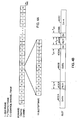
- FIG. 4A A diagram of the exemplary forward link frame structure of the present invention is illustrated in FIG. 4A .
- the traffic channel transmission is partitioned into frames which, in the exemplary embodiment, are defined as the length of the short PN sequences or 26.67 msec.
- Each frame can carry control channel information addressed to all subscriber stations 106 (control channel frame), traffic data addressed to a particular subscriber station 106 (traffic frame), or can be empty (idle frame).
- the content of each frame is determined by the scheduling performed by the transmitting base station 102 .
- each frame comprises 16 time slots, with each time slot having a duration of 1.667 msec.
- a time slot of 1.667 msec is adequate to enable subscriber station 106 to perform the C/I measurement of the forward link signal.
- a time slot of 1.667 msec also represents a sufficient amount of time for efficient packet data transmission.
- each forward link data packet comprises 1024 or 2048 bits.
- the number of time slots required to transmit each data packet is dependent on the data rate and ranges from 16 time slots for the 38.4 Kbps rate to 1 time slot for the 1.2288 Mbps rate and higher.
- each slot comprises three of the four time multiplexed channels, the traffic channel, the control channel, the pilot channel, and the overhead control channel.
- the pilot signal is transmitted in two bursts and the overhead control channel is transmitted on either side of the second pilot burst.
- the traffic data is carried in three portions of the slot ( 402a , 402b and 402c ).
- the first pilot burst 406a is time multiplexed into the first half of the slot by multiplexer 362 .
- the second pilot burst 406b is time multiplexed into the second half of the slot.
- One either side of second pilot burst 406b overhead channel data 408 including the forward activity bit, the busy tones and the power control bits are multiplexed into the slot.
- FIG. 5 illustrates subscriber station 106 of the present invention.
- Forward link signals are received at antenna 500 and provided through duplexer 502 to receiver 504 .
- receiver 504 is a quaternary phase shift keying (QPSK) receiver. It will be understood by one skilled in the art that the present invention is equally applicable to any other modulation format such as BPSK or QAM.
- QPSK quaternary phase shift keying
- the in-phase and quadrature-phase components of the received signal are provided to PN despreaders 506 .
- multiple PN despreaders 506A-506N are provided.
- Each of despreaders 506 is capable of demodulating a signal from a different base station in the Active set of subscriber station 106 or a different multipath component of ) the signal from a base station.
- the PN despread signal is provided to power control command (PCC) demodulator 508 .
- PCC demodulator 508 performs an FHT on the received power control symbols and determines whether the base station is requesting subscriber station 106 to increase or decrease its transmission energy.
- the demodulated power control symbols are provided to power control command combiner 516 .
- power control command combiner 516 soft combines multipath components of the power control command symbols from a single base station and generates a hard estimate of the power control command from each base station.
- the hard decision from each of the base stations is stored in memory 518 .
- a statistic representing the recent history of power control commands from each base station is stored in memory 518 .
- power control command combiner 516 performs an OR-of-the-downs operation in which the transmission energy of subscriber station 106 is only increased if all the power control commands indicate a need to increase the transmission energy.
- Power control command combiner 516 provides a control signal to transmitter (TMTR) 528 increasing or decreasing its amplification of the reverse link signal from subscriber station 106 .
- the PN despread signals from PN despreaders 506 are also provided to pilot demodulators 510 .
- Pilot demodulators 510 despread the pilot signal.
- the Walsh 0 function is used to spread the pilot signal, and as such pilot demodulators 510 are implemented as accumulators.
- the despread pilot signals are provided to energy calculators 512 .
- Energy calculators 512 compute the energy of the demodulated pilot bursts. In the exemplary embodiment, this operation is performed by summing the squares of the demodulated symbol amplitudes. The calculated energy values are provided to control processor 520 .
- Control Processor 520 sums the energies from multipath components of a common base station and generates and chip energy to interference ratio for each base station. Control processor 520 then selects the base station with the highest (C/I) and selects a requested rate for that base station. After the base station is selected the operation described in FIG. 1 is performed by control processor 520 .
- a signal indicative of the selected base station and a symbol indicative of the requested rate are provided to spreading element 524 .
- the rate request is spread by the signal indicative of the selected base station.
- This signal is multiplexed with other overhead data such as a reverse rate indicator (RRI) and the pilot symbols.
- RRI reverse rate indicator
- this data is provided on the in-phase component of a transmitted QPSK signal.
- the reverse link traffic data is modulated and provided for transmission on the quadrature phase component of the transmitted QPSK signal.
- Transmitter 528 upconverts amplifies and filters the signal for transmission.
- transmitter 528 also spreads the reverse link signal in accordance with a pseudonoise sequence.
- the signal is provided through duplexer 502 for transmission through antenna 500 .
Abstract
Description
- The present invention relates to wireless communications. More particularly, the present invention relates to a novel and improved method and apparatus for performing handoff in a wireless communications system.
- It has become very important for service providers to be able to provide high speed wireless services to their customers. A high speed wireless communication system is disclosed in copending
U S. Patent No. 6,574,211 (the '386 application), filed November 3, 1997, entitled, "METHOD AND APPARATUS FOR HIGHER RATE PACKET DATA TRANSMISSION", which is assigned to the assignee of the present invention. In the '386 application, the base station transmits to subscriber stations by sending frames that include a pilot burst time multiplexed in to the frame and transmitted at a rate based on channel information transmitted from the subscriber station to the base station. This system is optimized for the wireless transmission of digital data. - Code Division Multiple Access or CDMA has proven itself to be the predominant choice for wireless service providers because of its high spectral efficiency. One such CDMA communication system is described in the "TIA/EIA/IS-95 Subscriber station-Base Station Compatibility Standard for Dual-Mode Wideband Spread Spectrum Cellular System", hereinafter referred to as the IS-95 standard. The IS-95 CDMA system allows for voice and data communications between users over a terrestrial link. The use of CDMA techniques in a multiple access communication system is disclosed in
U. S. Patent No. 4,901,307 , entitled "SPREAD SPECTRUM MULTIPLE ACCESS COMMUNICATION SYSTEM USING SATELLITE OR TERRESTRIAL REPEATERS", andU. S. Patent No. 5,103, 459 , entitled "SYSTEM AND METHOD FOR GENERATING WAVEFORMS IN A CDMA CELLULAR TELEPHONE SYSTEM", both assigned to the assignee of the present invention. - In this specification base station refers to the hardware with which the subscriber stations communicate. Cell refers to the hardware or the geographic coverage area, depending on the context in which the term is used. A sector is a partition of a cell. Because a sector of a CDMA system has the attributes of a cell, the teachings described in terms of cells are readily extended to sectors.
- In the CDMA system, communications between users are conducted through one or more base stations. A first user on one subscriber station communicates to a second user on a second subscriber station by transmitting data on the reverse link to a base station. The base station receives the data and can route the data to another base station. The data is transmitted on the forward link of the same base station, or a second base station, to the second subscriber station. The forward link refers to transmission from the base station to a subscriber station and the reverse link refers to transmission from the subscriber station to a base station. In IS-95 systems, the forward link and the reverse link are allocated separate frequencies,
- The subscriber station communicates with at least one base station during a communication. CDMA subscriber stations are capable of communicating with multiple base stations simultaneously during soft handoff. Soft handoff is the process of establishing a link with a new base station before breaking the link with the previous base station. Soft handoff minimizes the probability of dropped calls. The method and system for providing a communication with a subscriber station through more than one base station during the soft handoff process are disclosed in
U. S. Patent No. 5, 267, 261 , entitled "MOBILE ASSISTED SOFT HANDOFF IN A CDMA CELLULAR TELEPHONE SYSTEM," assigned to the assignee of the present invention. Softer handoff is the process whereby the communication occurs over multiple sectors which are serviced by the same base station. The process of softer handoff is described in detail in copendingU. S. Patent No. 5,933,787 , entitled "METHOD AND APPARATUS FOR PERFORMING HANDOFF BETWEEN SECTORS OF A COMMON BASE STATION", filed December 11, 1996, assigned to the assignee of the present invention. - A significant difference between voice services and data services is the fact that the former imposes stringent and fixed delay requirements. Typically, the overall one-way delay of speech frames must be less than 100 msec. In contrast, the data delay can become a variable parameter used to optimize the efficiency of the data communication system. Specifically, more efficient error correcting coding techniques which require significantly larger delays than those that can be tolerated by voice services can be utilized. An exemplary efficient coding scheme for data is disclosed in
U. S. Patent No. 5,933,462 , entitled "SOFT DECISION OUTPUT DECODER FORDECODING CONVOLUTIONALLY ENCODED CODEWORDS", filed November 6, 1996, assigned to the assignee of the preserrt invention. - Another significant difference between voice services and data services is that the former requires a fixed and common grade of service (GOS) for all users. Typically, for digital systems providing voice services, this translates into a fixed and equal transmission rate for all users and a maximum tolerable value for the error rates of the speech frames. In contrast, for data services, the GOS can be different from user to user and can be a parameter optimized to increase the overall efficiency of the data communication system. The GOS of a data communication system is typically defined as the total delay incurred in the transfer of a predetermined amount of data, hereinafter referred to as a data packet.
- Yet another significant difference between voice services and data services is that the former requires a reliable e communication link which, in the exemplary CDMA communication system, is provided by soft handoff Soft handoff results in redundant transmissions from two or more base stations to improve reliability. However, this additional reliability is not required for data transmission because the data packets received in error can be retransmitted. For data services, the transmit power used to support soft handoff can be more efficiently used for transmitting additional data.
- The parameters which measure the quality and effectiveness of a data communication system are the transmission delay required to transfer a data packet and the average throughput rate of the system. Transmission delay does not have the same impact in data communication as it does for voice communication, but it is an important metric for measuring the quality of the data communication system. The average throughput rate is a measure of the efficiency of the data transmission capability of the communication system.
- It is well known that in cellular systems the signal-to-noise-and interference ratio C/I of any given user is a function of the location of the user within the coverage area. In order to maintain a given level of service, TDMA and FDMA systems resort to frequency reuse techniques, i.e. not all frequency channels and/or time slots are used in each base station. In a CDMA system, the same frequency allocation is reused in every cell of the system, thereby improving the overall efficiency. The C/I that any given user's subscriber station achieves determines the information rate that can be supported for this particular link from the base station to the user's subscriber station. Given the specific modulation and error correction method used for the transmission, which the present invention seek to optimize for data transmissions, a given level of performance is achieved at a corresponding level of C/I. For an idealized cellular system with hexagonal cell layouts and utilizing a common frequency in every cell, the distribution of C/I achieved within the idealized cells can be calculated.
- The C/I achieved by any given user is a function of the path loss, which for terrestrial cellular systems increases as r3 to r5, where r is the distance to the radiating source. Furthermore, the path loss is subject to random variations due to man-made or natural obstructions within the path of the radio wave. These random variations are typically modeled as a log normal shadowing random process with a standard deviation of 8 dB. The resulting C/I distribution achieved for an ideal hexagonal cellular layout with omni-directional base station antennas,r4 propagation law, and shadowing process with 8 dB standard deviation is shown in Fig. 10.
- The obtained C/I distribution can only be achieved if, at any instant in time and at any location, the subscriber station is served by the best base station which is defined as that achieving the largest C/I value, regardless of the physical distance to each base station. Because of the random nature of the path loss as described above, the signal with the largest C/I is not always transmitted by the base station closest to the subscriber station. In contrast, if a subscriber station was to communicate only via the base station of minimum distance, the C/1 can be substantially degraded. It is therefore beneficial for subscriber stations to communicate to and from the best serving base station at all times, thereby achieving the optimum C/1 value. It can also be observed that the range of values of the achieved C/I, in the above idealized model and as shown in FIG. 10, is such that the difference between the highest and lowest value can be as large as 10, 000. In practical implementation the range is typically limited to approximately 1:100 or 20 dB. It is therefore possible for a CDMA base station to serve subscriber stations with information bit rates that can vary by as much as a factor of 100, since the following relationship holds;

-
US Patent No. 5,345,467 discloses a CDMA cellular hand-off apparatus and method. This document discloses a method for controlling handoff in a spread-spectrum-CDMA-communications system, in which a time -, distance- or power level difference between signals received from a first and second base station is used to determine by a mobile station whether to initiate handoff from one base station to the other. Before having the first base station to notify the switch controller to handoff, the mobile station transmits all zeros to the second base station for performing an error test. - The present invention relates to a method for communications by a subscriber station, a subscriber station for communications and a computer program product as defined in the independent claims.
- The present invention is a novel and improved method for communications in a subscriber station, and a subscriber station for communications, which take into account the ability of a base station to receive the reverse link transmissions from the mobile station.
- The subscriber station receives the pilot signal and reverse link power control commands from all of the base stations in its Active Set. The subscriber station uses the received pilot signal for coherent demodulation of the forward link traffic signal and for determining the strength of the signal from each base station. In the exemplary embodiment, the power control commands from each base station direct the subscriber station to increase or decrease its transmission energy by predetermined amounts. In the exemplary embodiment, the subscriber station only increases its transmission energy when all the base stations in the Active Set request the subscriber station to increase its transmission energy.
- In the exemplary embodiment of the communication system described in the aforementioned
U.S. Patent Application Serial No. 08/963,386 , the high speed forward link traffic data is transmitted from only one base station. That is to say, the forward link traffic is not provided in soft handoff. This is a desirable constraint from the perspective of overall system capacity, because the redundant transmission required for soft handoff greatly impairs overall system capacity. In the exemplary embodiment, the subscriber station measures the signal energy of signals received from each of the base stations in the Active Set of the subscriber station and sends a data request control (DRC) signal indicating which base station is transmitting the strongest received signal. In addition, the DRC signal indicates a data rate which the subscriber station selects based on strength of the received signal from the selected base station. - In the exemplary embodiment of the present invention, the subscriber station stores an indication of the mix of power control commands transmitted by each base station. That is, for each base station an indicator respecting relative number of commands requesting an increase in transmission energy versus the number of power control commands requesting a decrease in transmission energy is stored. This statistic can be generated by a filtering of the power control commands from each base station. For example, an infinite impulse response filter can be used to perform an averaging of the commands. The implementation of averaging filters is well known in the art.
- In an alternative embodiment, the subscriber station stores the raw power control commands from each base station. In a second alternative embodiment, the subscriber station stores an indication of the number of consecutive or nearly consecutive requests to increase transmission energy from each base station. A series of requests to increase transmission energy indicates that the base station is not receiving the reverse link signal.
- The subscriber station makes an initial selection of the base station to transmit forward link data to it. In the exemplary embodiment, the subscriber station measures the energy of a time multiplexed pilot signal from each base station and selects the base station with the highest chip energy to interference (C/I) when including all multipath components from each base station. In the exemplary embodiment, the subscriber station includes a RAKE receiver that separately demodulates the multipath components of signals from each base station. An exemplary embodiment of a RAKE receiver is described in
U.S. Patent No. 5,103,390 . - The subscriber station determines whether the selected base station requires a handoff. That is to say, whether the selected base station is the same as the base station selected to transmit in the last frame interval.
- If the selected base station does require a handoff, then the subscriber uses the method of the present invention to determine if the selected base station is receiving its reverse link transmissions. In the exemplary embodiment, the subscriber station makes this determination by looking at the history of reverse link power control commands transmitted by the selected base station. A sufficient number of power control commands by a given base station requesting the subscriber station to decrease its transmission energy indicates that the reverse link signal is being received by the base station with sufficient energy. It will be understood that other methods of performing this analysis are equally applicable, for example the base stations could intermittently transmits a message indicating the average quality of the received reverse link signal.
- If the subscriber station determines that its reverse link signal is being received with sufficient energy by the selected base station, then the handoff is permitted. The subscriber station transmits a message indicative of the selected base station and the rate (or change in transmission power) requested to transmit to the subscriber station.
- If the subscriber station determines that its reverse link signal is not being received with sufficient energy by the selected base station, then the handoff is inhibited. In the exemplary embodiment, the subscriber station selects an alternative base station for transmission of forward link traffic data which is receiving its reverse link transmissions with sufficient energy. The subscriber station transmits a message indicative of the alternative base station and the rate requested to transmit to the subscriber station. The rate requested is based on the strength of the received pilot signal from the alternative base station.
- If a handoff is not necessary, then the subscriber station again determines whether the selected base station (which is the base station selected to transmit to the subscriber station in the last frame) is reliably receiving its reverse link signal. If the subscriber station determines that its reverse link signal is being received by the selected base station with sufficient energy, then the subscriber station transmits a message indicative of the selected base station and the rate requested to transmit to the subscriber station.
- If the subscriber station determines that its reverse link signal is not being received with sufficient energy by the selected base station, then a handoff is forced. The subscriber station selects an alternative base station for transmission of forward link traffic data, which is receiving its reverse link transmissions with sufficient energy. The subscriber station transmits a message indicative of the alternative base station and the rate requested to transmit to the subscriber station. The rate or power requested is based on the strength of the received pilot signal from the alternative base station.
- The features, objects, and advantages of the present invention will become more apparent from the detailed description set forth below when taken in conjunction with the drawings in which like reference characters identify correspondingly throughout and wherein:
-
FIG. 1 is a flowchart illustrating the method of the ; -
FIG. 2 is a basic diagram illustrating the handoff condition of the present invention; -
FIGS. 3A and3B are block diagrams of the exemplary embodiment of the base station of the present invention; -
FIG. 4A is a diagram of the frame structure of the present invention; -
FIG. 4B is a diagram of the slot structure of the present invention; and -
FIG. 5 is a block diagram of the subscriber station of the present invention. - Referring to
FIG. 1 , inblock 100, the subscriber station receives the pilot signal and reverse link power control commands from all of the base stations in its Active Set. The subscriber station uses the received pilot signal for coherent demodulation of the forward link traffic signal and for determining the strength of the signal from each base station. In the exemplary embodiment, the power control commands from each base station direct the subscriber station to increase or decrease its transmission energy. In the exemplary embodiment, the subscriber station only increases its transmission energy if no base stations in the Active Set request the subscriber station to decrease its transmission energy. - In the exemplary embodiment of the communication system described in the aforementioned
U.S. Patent Application Serial No. 08/963,386 , the high speed traffic data is transmitted from only one base station. That is to say, the forward link traffic is not provided in soft handoff. This is a desirable constraint from the perspective of overall system capacity. In the exemplary, the subscriber station measure the signal energy of signals from each of the base stations in the Active Set of the subscriber station and sends a data request control (DRC) signal indicating which base station is transmitting the strongest received signal. In addition, the DRC signal indicates a data rate which the subscriber station selects based on strength of the received signal from the selected base station. - In
block 102, the subscriber station stores the reverse link power control commands from each base station in memory. In an alternative embodiment, the subscriber station stores a statistic indicative of the power control commands received from each base station, such as the fraction of commands received that requested a decrease in transmission energy in a predetermined number of preceding frames or the number of discrepancies between the base station's request and the response taken by the subscriber station. - In
block 104, the subscriber station makes an initial selection of the base station to transmit forward link data to it. In the exemplary embodiment, the subscriber station measures the energy of a time multiplexed pilot signal from each base station and selects the base station with the highest chip energy to interference (C/I) when including all multipath components. In the exemplary embodiment, the subscriber station includes a RAKE receiver that separately demodulates the multipath components of signals from each base station. An exemplary embodiment of a RAKE receiver is described inU.S. Patent No. 5,103,390 . - In
block 106, the subscriber station determines whether the selected base station requires a handoff. That is to say, whether the selected base station is the same as the base station selected to transmit in the last frame interval. - If the selected base station does require a handoff, then the process moves to block 108. In block, 108, the subscriber determines if the selected base station is receiving its reverse link transmissions. In the exemplary embodiment, the subscriber station makes this determination by looking at the history of reverse link power control commands transmitted by the selected base station. A sufficient number of power control commands requesting the subscriber station to decrease its transmission energy is indicative that the signal strength of its reverse link transmissions are being received by the selected base station. It will be understood that other methods of performing this analysis are equally applicable, for example the base stations could intermittently transmits a message indicating the average quality of the received reverse link signal.
- If the subscriber station determines that its reverse link signal is being reliably received by the selected base station, then the process moves to block 110. In
block 110, the handoff is permitted. The subscriber station transmits a data rate control (DRC)message indicative of the selected base station and the rate requested to transmit to the subscriber station. - If the subscriber station determines that its reverse link signal is not being reliably received by the selected base station, then the process moves to block 112. In
block 112, the handoff is inhibited. In the exemplary embodiment, the subscriber station selects an alternative base station for transmission of forward link traffic data which is reliably receiving its reverse link transmissions. The subscriber station transmits a DRC message indicative of the alternative base station and the rate requested to transmit to the subscriber station. The rate requested is based on the strength of the received pilot signal from the alternative base station. - Back in
block 106, if a handoff is not necessary, then the process moves to block 114. Inblock 114, the subscriber station again determines whether the selected base station (which is the base station previously selected) is receiving its reverse link signal with sufficient energy. The determination as to whether the base station is reliably receiving the reverse link signal proceeds as described with respect to block 108 above. - If the subscriber station determines that its reverse link signal is being received with sufficient energy by the selected base station, then the process moves to block 116. In
block 116, the subscriber station transmits a message indicative of the selected base station and the rate requested to transmit to the subscriber station. - If the subscriber station determines that its reverse link signal is not being reliably received by the selected base station, then the process moves to block 118. In
block 118, a handoff is forced. The subscriber station selects an alternative base station for transmission of forward link traffic data, which is receiving its reverse link transmissions with sufficient energy. The subscriber station transmits a DRC message indicative of the alternative base station and the rate requested to transmit to the subscriber station. The rate requested is based on the strength of the received pilot signal from the alternative base station. - Referring to the figures,
FIG. 2 represents the exemplary data communication system of the present invention which comprises multiple cells 200a-200f. Each cell 200 is serviced by a corresponding base station 202 or base station 204. Base stations 202 are base stations that are in active communication withsubscriber station 206 and are said to make up the active set ofsubscriber station 206. Base stations 204 are not in communication withsubscriber station 206 but have signals with sufficient strength to be monitored bysubscriber station 206 for addition to the active set if the strength of the received signals increases due to a change in the propagation path characteristics. Base stations 204 are said to make up the candidate set ofsubscriber station 206. - In the exemplary embodiment,
subscriber station 206 receives information from at most one base station 202 on the forward link at each time slot, but can be in communication with one or more base stations 202 on the reverse link, depending on whether thesubscriber station 206 is in soft handoff. As shown byFIG. 1 , each base station 202 preferably transmits data to onesubscriber station 206 at any given moment.Subscriber stations 206, especially those located near a cell boundary, can receive the pilot signals from multiple base stations 204 in the candidate set. If the pilot signal is above a predetermined threshold,subscriber station 206 can request that base station 204 be added to the active set ofsubscriber station 206. In the exemplary embodiment,subscriber station 206 can receive data transmission from zero or one member of the active set. - A block diagram of the exemplary forward link architecture of the present invention is shown in
FIG. 3A . The data is partitioned into data packets and provided toCRC encoder 312. For each data packet,CRC encoder 312 generates frame check bits (e.g., the CRC parity bits) and inserts the code tail bits. The formatted packet fromCRC encoder 312 comprises the data, the frame check and code tail bits, and other overhead bits which are described below. The formatted packet is provided to encoder 314 which, in the exemplary embodiment, encodes the data in accordance with a convolutional or turbo encoding format. The encoded packet fromencoder 314 is provided to interleaver 316 which reorders the code symbols in the packet. The interleaved packet is provided to framepuncture element 318 which removes a fraction of the packet in the manner described below. The punctured packet is provided tomultiplier 320 which scrambles the data with the scrambling sequence fromscrambler 322. The output frommultiplier 320 comprises the scrambled packet.
The scrambled packet is provided tovariable rate controller 330 which demultiplexes the packet into K parallel in-phase and quadrature-phase channels, where K is dependent on the data rate. In the exemplary embodiment, the scrambled packet is first demultiplexed into the in-phase (I) and quadrature-phase (Q) streams. In the exemplary embodiment, the I stream comprises even indexed symbols and the Q stream comprises odd indexed symbol. - Each stream is further demultiplexed into K parallel channels such that the symbol rate of each channel is fixed for all data rates. The K channels of each stream are provided to
Walsh cover element 332 which covers each channel with a Walsh function to provide orthogonal channels. The orthogonal channel data is provided to gainelement 334 which scales the data to maintain a constant total-energy-per-chip (and hence constant output power) for all data rates. The scaled data fromgain element 334 is provided to multiplexer (MUX) 360 which multiplexes the data with a preamble sequence. The output fromMUX 360 is provided to multiplexer (MUX) 362 which multiplexes the traffic data, the power control bits, and the pilot data. The output ofMUX 362 comprises the I Walsh channels and the Q Walsh channels. - The reverse link power control (RPC) bits are provided to
symbol repeater 350 which repeats each RPC bit a predetermined number of times. The repeated RPC bits are provided toWalsh cover element 352 which covers the bits with the Walsh covers corresponding to the RPC indices. The covered bits are provided to gainelement 354 which scales the bits prior to modulation so as to maintain a constant total transmit power. - In addition, a forward activity bit is provided to
symbol repeater 350. The forward activity bitalerts subscriber station 106 to a forthcoming blank frame in which the base station will not transmit forward link data. This transmission is made in order to allowsubscriber station 106 to make a better estimate of the C/I of the signal frombase stations 102. The repeated versions of the forward activity bit are Walsh covered inWalsh cover element 352 so as to be orthogonal to the Walsh covered power control bits. The covered bits are provided to gainelement 354 which scales the bits prior to modulation so as to maintain a constant total transmit power. - In addition, a busy tone is provided to
symbol repeater 350. The busy tone alertssubscriber station 106 to a reverse link loading condition. In an exemplary embodiment, the busy tone is a single bit indicative of the reverse link being fully loaded or having capacity. In the preferred embodiment, the busy tone is a two bit signal indicative of a request bybase stations 102 forsubscriber stations 106 in its coverage area to either deterministically increase or decrease the rate of their reverse link transmissions, or to stochastically increase or decrease the rate of their reverse link transmissions. The repeated versions of the busy tone is Walsh covered inWalsh cover element 352 so as to be orthogonal to the Walsh covered power control bits and forward activity bit. The covered bit is provided to gainelement 354 which scales the bits prior to modulation so as to maintain a constant total transmit power. - The pilot data comprises a sequence of all zeros (or all ones) which is provided to
multiplier 356.Multiplier 356 covers the pilot data with Walsh code W0. Since Walsh code W0 is a sequence of all zeros, the output ofmultiplier 356 is the pilot data. The pilot data is time multiplexed byMUX 362 and provided to the I Walsh channel which is spread by the short PNI code within complex multiplier 366 (seeFIG. 3B ). In the exemplary embodiment, the pilot data is not spread with the long PN code, which is gated off during the pilot burst byMUX 376, to allow reception by allsubscriber stations 376. The pilot signal is thus an unmodulated BPSK signal. - A block diagram of the exemplary modulator used to modulate the data is illustrated in
FIG. 3B . The I Walsh channels and Q Walsh channels are provided to summers 364a and 364b, respectively, which sum the K Walsh channels to provide the signals Isum and Qsum, respectively. The Isum and Qsum signals are provided tocomplex multiplier 366.Complex multiplier 366 also receives the PN_I and PN_Q signals from multipliers 378a and 378b, respectively, and multiplies the two complex inputs in accordance with the following equation :
where Imult and Qmult are the outputs fromcomplex multiplier 366 and j is the complex representation. The Imult and Qmult signals are provided to filters 368a and 368b, respectively, which filter the signals. The filtered signals from filters 368a and 368b are provided to multipliers 370a and 370b, respectively, which multiply the signals with the in-phase sinusoid COS(wct) and the quadrature-phase sinusoid SIN(wct), respectively. The I modulated and Q modulated signals are provided tosummer 372 which sums the signals to provide the forward modulated waveform S(t). - In the exemplary embodiment, the data packet is spread with the long PN code and the short PN codes. The long PN code scrambles the packet such that only the
subscriber station 106 for which the packet is destined is able to descramble the packet. In the exemplary embodiment, the pilot and power control bits and the control channel packet are spread with the short PN codes but not the long PN code to allow allsubscriber stations 106 to receive these bits. The long PN sequence is generated bylong code generator 374 and provided to multiplexer (MUX) 376. The long PN mask determines the offset of the long PN sequence and is uniquely assigned to thedestination subscriber station 106. The output fromMUX 376 is the long PN sequence during the data portion of the transmission and zero otherwise (e.g. during the pilot and power control portion). The gated long PN sequence fromMUX 376 and the short PN1 and PNQ sequences fromshort code generator 380 are provided to multipliers 378a and 378b, respectively, which multiply the two sets of sequences to form the PN_I and PN_Q signals, respectively. The PN_I and PN_Q signals are provided tocomplex multiplier 366. - The block diagram of the exemplary traffic channel shown in
FIGS.3A and3B is one of numerous architectures which support data encoding and modulation on the forward link. Other architectures, such as the architecture for the forward link traffic channel in the CDMA system which conforms to the IS-95 standard, can also be utilized and are within the scope of the present invention. - A diagram of the exemplary forward link frame structure of the present invention is illustrated in
FIG. 4A . The traffic channel transmission is partitioned into frames which, in the exemplary embodiment, are defined as the length of the short PN sequences or 26.67 msec. Each frame can carry control channel information addressed to all subscriber stations 106 (control channel frame), traffic data addressed to a particular subscriber station 106 (traffic frame), or can be empty (idle frame). The content of each frame is determined by the scheduling performed by the transmittingbase station 102. In the exemplary embodiment, each frame comprises 16 time slots, with each time slot having a duration of 1.667 msec. A time slot of 1.667 msec is adequate to enablesubscriber station 106 to perform the C/I measurement of the forward link signal. A time slot of 1.667 msec also represents a sufficient amount of time for efficient packet data transmission. - In the exemplary embodiment, each forward link data packet comprises 1024 or 2048 bits. Thus, the number of time slots required to transmit each data packet is dependent on the data rate and ranges from 16 time slots for the 38.4 Kbps rate to 1 time slot for the 1.2288 Mbps rate and higher.
- An exemplary diagram of the forward link slot structure of the present invention is shown in
FIG. 4B . In the exemplary embodiment, each slot comprises three of the four time multiplexed channels, the traffic channel, the control channel, the pilot channel, and the overhead control channel. In the exemplary embodiment, the pilot signal is transmitted in two bursts and the overhead control channel is transmitted on either side of the second pilot burst. The traffic data is carried in three portions of the slot (402a, 402b and 402c). - The first pilot burst 406a is time multiplexed into the first half of the slot by
multiplexer 362. The second pilot burst 406b is time multiplexed into the second half of the slot. One either side of second pilot burst 406b overhead channel data 408 including the forward activity bit, the busy tones and the power control bits are multiplexed into the slot. -
FIG. 5 illustratessubscriber station 106 of the present invention. Forward link signals are received atantenna 500 and provided throughduplexer 502 toreceiver 504. In the exemplary embodiment,receiver 504 is a quaternary phase shift keying (QPSK) receiver. It will be understood by one skilled in the art that the present invention is equally applicable to any other modulation format such as BPSK or QAM. - The in-phase and quadrature-phase components of the received signal are provided to PN despreaders 506. In the exemplary embodiment, multiple PN despreaders 506A-506N are provided. Each of despreaders 506 is capable of demodulating a signal from a different base station in the Active set of
subscriber station 106 or a different multipath component of ) the signal from a base station. - The PN despread signal is provided to power control command (PCC) demodulator 508. In the exemplary embodiment, PCC demodulator 508 performs an FHT on the received power control symbols and determines whether the base station is requesting
subscriber station 106 to increase or decrease its transmission energy. - The demodulated power control symbols are provided to power
control command combiner 516. In the exemplary embodiment, powercontrol command combiner 516 soft combines multipath components of the power control command symbols from a single base station and generates a hard estimate of the power control command from each base station. The hard decision from each of the base stations is stored inmemory 518. In an alternative embodiment, a statistic representing the recent history of power control commands from each base station is stored inmemory 518.
Then, powercontrol command combiner 516 performs an OR-of-the-downs operation in which the transmission energy ofsubscriber station 106 is only increased if all the power control commands indicate a need to increase the transmission energy. Powercontrol command combiner 516 provides a control signal to transmitter (TMTR) 528 increasing or decreasing its amplification of the reverse link signal fromsubscriber station 106. - The PN despread signals from PN despreaders 506 are also provided to pilot demodulators 510. Pilot demodulators 510 despread the pilot signal. In the exemplary embodiment, the Walsh 0 function is used to spread the pilot signal, and as such pilot demodulators 510 are implemented as accumulators. The despread pilot signals are provided to energy calculators 512. Energy calculators 512 compute the energy of the demodulated pilot bursts. In the exemplary embodiment, this operation is performed by summing the squares of the demodulated symbol amplitudes. The calculated energy values are provided to control
processor 520. -
Control Processor 520 sums the energies from multipath components of a common base station and generates and chip energy to interference ratio for each base station.Control processor 520 then selects the base station with the highest (C/I) and selects a requested rate for that base station. After the base station is selected the operation described inFIG. 1 is performed bycontrol processor 520. - After performing the selection process described with respect to
FIG. 1 , a signal indicative of the selected base station and a symbol indicative of the requested rate are provided to spreadingelement 524. In the exemplary embodiment, the rate request is spread by the signal indicative of the selected base station. This signal is multiplexed with other overhead data such as a reverse rate indicator (RRI) and the pilot symbols. In the exemplary embodiment, this data is provided on the in-phase component of a transmitted QPSK signal. The reverse link traffic data is modulated and provided for transmission on the quadrature phase component of the transmitted QPSK signal. -
Transmitter 528 upconverts amplifies and filters the signal for transmission. In the exemplary embodiment,transmitter 528 also spreads the reverse link signal in accordance with a pseudonoise sequence. The signal is provided throughduplexer 502 for transmission throughantenna 500. - The previous description of the preferred embodiments is provided to enable any person skilled in the art to make or use the present invention. The various modifications to these embodiments will be readily apparent to those skilled in the art, and the generic principles defined herein may be applied to other embodiments without the use of the inventive faculty. Thus, the present invention is not intended to be limited to the embodiments shown herein but is to be accorded the widest scope as defined by the appended claims.
Claims (15)
- A method for communications by a subscriber station (206), comprising:initially selecting (104), by a subscriber station, a base station (202, 204) for transmission of forward link data;determining (106), by the subscriber station, if a handoff to the base station is necessary;determining (108) by the subscriber station if the base station receives reverse link transmissions from the subscriber station with sufficient energy; andperforming the handoff to the base station if the base station receives the reverse link transmissions with sufficient energy.
- The method of claim 1, wherein the determining if the base station receives reverse link transmissions with sufficient energy is based in part on a message indicating a reverse link quality received from the base station.
- The method of claim 1, wherein the determining if the base station receives reverse link transmissions with sufficient energy is based in part on reverse link power control commands received from the base station.
- The method of claim 1, wherein the performing the handoff further comprises prohibiting (112) the handoff to the base station if the base station does not receive reverse link transmissions with sufficient energy.
- The method of claim 1, wherein the performing the handoff further comprises allowing (110) the handoff to the base station if the base station receives reverse link transmissions with sufficient energy.
- A subscriber station (206) for communications, comprising:means for initially selecting (104) a base station (202A-202C, 204A-204C) for transmission of forward link data;means for determining (106) if a handoff to the base station is necessary;means for determining (108) by the subscriber station if the base station receives reverse link transmissions from the subscriber station with sufficient energy; andmeans for performing the handoff to the base station if the base station receives the reverse link transmissions with sufficient energy.
- The subscriber station of claim 6, wherein the means for determining if the base station receives reverse link transmissions with sufficient energy further comprises means for receiving a message indicating a reverse link quality from the base station.
- The subscriber station of claim 6, wherein the means for determining if the base station receives reverse link transmissions with sufficient energy further comprises means for receiving reverse link power control commands from the base station.
- The subscriber station of claim 6, wherein the means for performing the handoff further comprises means for prohibiting (112) the handoff to the base station if the base station does not receive reverse link transmissions with sufficient energy.
- The subscriber station of claim 6, wherein the means for performing the handoff further comprises means for allowing (110) the handoff to the base station if the base station receives reverse link transmissions with sufficient energy.
- A computer program product, comprising:code for initially selecting (104), by a subscriber station, a base station for transmission of forward link data;code for determining (106) by the subscriber station if a handoff to the base station is necessary;code for determining (108) by the subscriber station if the base station receives reverse link transmissions from the subscriber station with sufficient energy; andcode for performing the handoff to the base station if the base station receives the reverse link transmissions with sufficient energy.
- The computer program product of claim 11, wherein the code for determining if the base station receives reverse link transmissions with sufficient energy further comprises code for receiving a message indicating a reverse link quality from the base station.
- The computer program product of claim 11, wherein the code for determining if the base station receives reverse link transmissions with sufficient energy further comprises code for receiving reverse link power control commands from the base station.
- The computer program product of claim 11, wherein the code for performing the handoff further comprises code for prohibiting (112) the handoff to the base station if the base station does not receive reverse link transmissions with sufficient energy.
- The computer program product of claim 11, wherein the code for performing the handoff further comprises code for allowing (110) the handoff to the base station if the base station receives reverse link transmissions with sufficient energy.
Priority Applications (1)
| Application Number | Priority Date | Filing Date | Title |
|---|---|---|---|
| EP10174223.7A EP2257105B1 (en) | 1999-11-04 | 2000-11-06 | Method for performing handoff by sequentially using up- and downlink signal quality |
Applications Claiming Priority (2)
| Application Number | Priority Date | Filing Date | Title |
|---|---|---|---|
| US09/434,314 US7206580B2 (en) | 1999-11-04 | 1999-11-04 | Method and apparatus for performing handoff in a high speed communication system |
| EP00975597A EP1226722B1 (en) | 1999-11-04 | 2000-11-06 | Method for performing handoff by sequentially using up- and downlink signal quality |
Related Parent Applications (2)
| Application Number | Title | Priority Date | Filing Date |
|---|---|---|---|
| EP00975597.6 Division | 2000-11-06 | ||
| EP00975597A Division EP1226722B1 (en) | 1999-11-04 | 2000-11-06 | Method for performing handoff by sequentially using up- and downlink signal quality |
Related Child Applications (2)
| Application Number | Title | Priority Date | Filing Date |
|---|---|---|---|
| EP10174223.7A Division EP2257105B1 (en) | 1999-11-04 | 2000-11-06 | Method for performing handoff by sequentially using up- and downlink signal quality |
| EP10174223.7 Division-Into | 2010-08-26 |
Publications (2)
| Publication Number | Publication Date |
|---|---|
| EP1855503A1 EP1855503A1 (en) | 2007-11-14 |
| EP1855503B1 true EP1855503B1 (en) | 2013-05-01 |
Family
ID=23723726
Family Applications (3)
| Application Number | Title | Priority Date | Filing Date |
|---|---|---|---|
| EP00975597A Expired - Lifetime EP1226722B1 (en) | 1999-11-04 | 2000-11-06 | Method for performing handoff by sequentially using up- and downlink signal quality |
| EP07115321.7A Expired - Lifetime EP1855503B1 (en) | 1999-11-04 | 2000-11-06 | Method for performing handoff by sequentially using up- and downlink signal quality |
| EP10174223.7A Expired - Lifetime EP2257105B1 (en) | 1999-11-04 | 2000-11-06 | Method for performing handoff by sequentially using up- and downlink signal quality |
Family Applications Before (1)
| Application Number | Title | Priority Date | Filing Date |
|---|---|---|---|
| EP00975597A Expired - Lifetime EP1226722B1 (en) | 1999-11-04 | 2000-11-06 | Method for performing handoff by sequentially using up- and downlink signal quality |
Family Applications After (1)
| Application Number | Title | Priority Date | Filing Date |
|---|---|---|---|
| EP10174223.7A Expired - Lifetime EP2257105B1 (en) | 1999-11-04 | 2000-11-06 | Method for performing handoff by sequentially using up- and downlink signal quality |
Country Status (12)
| Country | Link |
|---|---|
| US (3) | US7206580B2 (en) |
| EP (3) | EP1226722B1 (en) |
| JP (1) | JP4455798B2 (en) |
| KR (1) | KR100751971B1 (en) |
| CN (2) | CN100379311C (en) |
| AT (1) | ATE381868T1 (en) |
| AU (1) | AU777687B2 (en) |
| BR (1) | BRPI0015250B1 (en) |
| DE (1) | DE60037533T2 (en) |
| ES (1) | ES2295064T3 (en) |
| HK (1) | HK1056075A1 (en) |
| WO (1) | WO2001033871A2 (en) |
Families Citing this family (51)
| Publication number | Priority date | Publication date | Assignee | Title |
|---|---|---|---|---|
| US7206580B2 (en) * | 1999-11-04 | 2007-04-17 | Qualcomm Incorporated | Method and apparatus for performing handoff in a high speed communication system |
| US6996069B2 (en) * | 2000-02-22 | 2006-02-07 | Qualcomm, Incorporated | Method and apparatus for controlling transmit power of multiple channels in a CDMA communication system |
| US6944143B1 (en) | 2000-03-31 | 2005-09-13 | Qualcomm Incorporated | Prioritization of searching by a remote unit in a wireless communication system |
| US7224719B1 (en) | 2000-03-31 | 2007-05-29 | Qualcomm, Incorporated | Fast acquisition of a pilot signal in a wireless communication device |
| US7911993B2 (en) | 2000-07-19 | 2011-03-22 | Ipr Licensing, Inc. | Method and apparatus for allowing soft handoff of a CDMA reverse link utilizing an orthogonal channel structure |
| US8537656B2 (en) | 2000-07-19 | 2013-09-17 | Ipr Licensing, Inc. | Method for compensating for multi-path of a CDMA reverse link utilizing an orthogonal channel structure |
| WO2002045372A2 (en) * | 2000-11-29 | 2002-06-06 | British Telecommunications Public Limited Company | Transmitting and receiving real-time data |
| US6760597B2 (en) * | 2000-12-08 | 2004-07-06 | Lucent Technologies Inc. | Power control method for CDMA wireless communication networks |
| US6917581B2 (en) | 2001-07-17 | 2005-07-12 | Ipr Licensing, Inc. | Use of orthogonal or near orthogonal codes in reverse link |
| GB0120033D0 (en) * | 2001-08-16 | 2001-10-10 | Fujitsu Ltd | Cell selection |
| CN1557072A (en) * | 2001-09-21 | 2004-12-22 | ���˹���Ѷ��� | Data communications method and system using buffer size to calculate transmission rate for congestion control |
| US7548506B2 (en) * | 2001-10-17 | 2009-06-16 | Nortel Networks Limited | System access and synchronization methods for MIMO OFDM communications systems and physical layer packet and preamble design |
| WO2003049373A1 (en) * | 2001-11-30 | 2003-06-12 | British Telecommunications Public Limited Company | Data transmission |
| JP3880862B2 (en) | 2002-01-29 | 2007-02-14 | 富士フイルムホールディングス株式会社 | Imaging device |
| CA2479585A1 (en) * | 2002-03-27 | 2003-10-09 | Timothy Ralph Jebb | Data structure for data streaming system |
| EP1359722A1 (en) * | 2002-03-27 | 2003-11-05 | BRITISH TELECOMMUNICATIONS public limited company | Data streaming system and method |
| US7061971B2 (en) * | 2002-07-11 | 2006-06-13 | Qualcomm Incorporated | Method and apparatus for diversity searching and demodulator assignment in a wireless communication system |
| US7085582B2 (en) * | 2002-07-31 | 2006-08-01 | Motorola, Inc. | Pilot information gain control method and apparatus |
| US6725044B2 (en) * | 2002-08-15 | 2004-04-20 | Thomson Licensing S.A. | Technique seamless handoff of a mobile terminal user from a wireless telephony network to a wireless LAN |
| US6985733B2 (en) * | 2002-08-15 | 2006-01-10 | Motorola, Inc. | Method and apparatus for scanning for neighboring cells |
| US8400979B2 (en) * | 2003-01-07 | 2013-03-19 | Qualcomm Incorporated | Forward link handoff for wireless communication systems with OFDM forward link and CDMA reverse link |
| US7783312B2 (en) * | 2003-01-23 | 2010-08-24 | Qualcomm Incorporated | Data throughput improvement in IS2000 networks via effective F-SCH reduced active set pilot switching |
| US7072630B2 (en) * | 2003-03-06 | 2006-07-04 | Qualcomm, Inc. | Adaptive data rate determination for a reverse link communication in a communication system |
| GB0306296D0 (en) * | 2003-03-19 | 2003-04-23 | British Telecomm | Data transmission |
| KR100689508B1 (en) * | 2003-09-04 | 2007-03-02 | 삼성전자주식회사 | Method for performing handover in a communication system |
| US7292856B2 (en) | 2004-12-22 | 2007-11-06 | Qualcomm Incorporated | Methods and apparatus for flexible forward-link and reverse-link handoffs |
| US8254360B2 (en) | 2005-06-16 | 2012-08-28 | Qualcomm Incorporated | OFDMA control channel interlacing |
| US7983674B2 (en) | 2005-06-16 | 2011-07-19 | Qualcomm Incorporated | Serving base station selection in a wireless communication system |
| KR100975715B1 (en) * | 2005-06-27 | 2010-08-12 | 삼성전자주식회사 | Method for determinning handoff in a mobile communication system |
| US8249192B2 (en) * | 2005-07-18 | 2012-08-21 | Nokia Corporation | Techniques to transmit data rate control signals for multi-carrier wireless systems |
| US7583689B2 (en) * | 2005-11-01 | 2009-09-01 | Alcatel Lucent | Distributed communication equipment architectures and techniques |
| US7706811B2 (en) | 2006-09-19 | 2010-04-27 | Broadphone Llc | Signal comparison-based location determining method |
| US8126454B2 (en) | 2006-10-27 | 2012-02-28 | Research In Motion Limited | Link quality measurements based on data rate and received power level |
| US8891489B2 (en) * | 2007-03-19 | 2014-11-18 | Qualcomm Incorporated | Handover mechanism that exploits uplink channel quality of a target cell |
| US8170477B2 (en) * | 2008-04-04 | 2012-05-01 | Broadcom Corporation | Robust wireless communication device |
| US8331975B2 (en) * | 2008-12-03 | 2012-12-11 | Interdigital Patent Holdings, Inc. | Uplink power control for distributed wireless communication |
| FR2943163A1 (en) * | 2009-03-11 | 2010-09-17 | Cryptiris | SPATIAL LOCATION DEVICE, REFERENCE TRANSMITTER AND ASSOCIATED LOCATION SYSTEM |
| KR101641106B1 (en) | 2010-06-09 | 2016-07-20 | 삼성전자주식회사 | Method of communication for mobile terminal, pico base station and macro base station in heterogeneous network |
| US10756860B2 (en) | 2018-11-05 | 2020-08-25 | XCOM Labs, Inc. | Distributed multiple-input multiple-output downlink configuration |
| US10659112B1 (en) | 2018-11-05 | 2020-05-19 | XCOM Labs, Inc. | User equipment assisted multiple-input multiple-output downlink configuration |
| US10812216B2 (en) | 2018-11-05 | 2020-10-20 | XCOM Labs, Inc. | Cooperative multiple-input multiple-output downlink scheduling |
| US10432272B1 (en) | 2018-11-05 | 2019-10-01 | XCOM Labs, Inc. | Variable multiple-input multiple-output downlink user equipment |
| CN113169764A (en) | 2018-11-27 | 2021-07-23 | 艾斯康实验室公司 | Non-coherent cooperative multiple-input multiple-output communication |
| US10756795B2 (en) | 2018-12-18 | 2020-08-25 | XCOM Labs, Inc. | User equipment with cellular link and peer-to-peer link |
| US11063645B2 (en) | 2018-12-18 | 2021-07-13 | XCOM Labs, Inc. | Methods of wirelessly communicating with a group of devices |
| US11330649B2 (en) | 2019-01-25 | 2022-05-10 | XCOM Labs, Inc. | Methods and systems of multi-link peer-to-peer communications |
| US10756767B1 (en) | 2019-02-05 | 2020-08-25 | XCOM Labs, Inc. | User equipment for wirelessly communicating cellular signal with another user equipment |
| US10686502B1 (en) | 2019-04-29 | 2020-06-16 | XCOM Labs, Inc. | Downlink user equipment selection |
| US10735057B1 (en) | 2019-04-29 | 2020-08-04 | XCOM Labs, Inc. | Uplink user equipment selection |
| US11411778B2 (en) | 2019-07-12 | 2022-08-09 | XCOM Labs, Inc. | Time-division duplex multiple input multiple output calibration |
| US11411779B2 (en) | 2020-03-31 | 2022-08-09 | XCOM Labs, Inc. | Reference signal channel estimation |
Family Cites Families (60)
| Publication number | Priority date | Publication date | Assignee | Title |
|---|---|---|---|---|
| US4222115A (en) | 1978-03-13 | 1980-09-09 | Purdue Research Foundation | Spread spectrum apparatus for cellular mobile communication systems |
| US4475010A (en) | 1983-05-05 | 1984-10-02 | At&T Bell Laboratories | High density cellular mobile radio communications |
| US4901307A (en) | 1986-10-17 | 1990-02-13 | Qualcomm, Inc. | Spread spectrum multiple access communication system using satellite or terrestrial repeaters |
| US4718081A (en) | 1986-11-13 | 1988-01-05 | General Electric Company | Method and apparatus for reducing handoff errors in a cellular radio telephone communications system |
| US5327577A (en) | 1988-06-14 | 1994-07-05 | Telefonaktiebolaget L M Ericsson | Handover method for mobile radio system |
| SE8802229D0 (en) | 1988-06-14 | 1988-06-14 | Ericsson Telefon Ab L M | MOBILE RADIO STATION PROCEDURE |
| US5127100A (en) | 1989-04-27 | 1992-06-30 | Motorola, Inc. | Digital radio communication system and two way radio |
| US5109390A (en) | 1989-11-07 | 1992-04-28 | Qualcomm Incorporated | Diversity receiver in a cdma cellular telephone system |
| US5101501A (en) | 1989-11-07 | 1992-03-31 | Qualcomm Incorporated | Method and system for providing a soft handoff in communications in a cdma cellular telephone system |
| US5056109A (en) | 1989-11-07 | 1991-10-08 | Qualcomm, Inc. | Method and apparatus for controlling transmission power in a cdma cellular mobile telephone system |
| US5054110A (en) | 1989-12-29 | 1991-10-01 | Motorola, Inc. | Multi-site dispatching system cell registration |
| US5103459B1 (en) | 1990-06-25 | 1999-07-06 | Qualcomm Inc | System and method for generating signal waveforms in a cdma cellular telephone system |
| US5103390A (en) | 1990-09-10 | 1992-04-07 | Prodigit Electronics Co. Ltd. | AC load simulator |
| US5179571A (en) | 1991-07-10 | 1993-01-12 | Scs Mobilecom, Inc. | Spread spectrum cellular handoff apparatus and method |
| US5345467A (en) * | 1991-07-10 | 1994-09-06 | Interdigital Technology Corp. | CDMA cellular hand-off apparatus and method |
| US5267261A (en) * | 1992-03-05 | 1993-11-30 | Qualcomm Incorporated | Mobile station assisted soft handoff in a CDMA cellular communications system |
| SE9200915D0 (en) * | 1992-03-24 | 1992-03-24 | Ericsson Telefon Ab L M | METHODS IN A CELLULAR MOBILE RADIO COMMUNINCATION SYSTEM |
| US5491717A (en) * | 1993-10-18 | 1996-02-13 | Motorola, Inc. | Method for controlling transmission during handoff in a communication system |
| US6157668A (en) * | 1993-10-28 | 2000-12-05 | Qualcomm Inc. | Method and apparatus for reducing the average transmit power of a base station |
| ZA948133B (en) | 1993-10-28 | 1996-05-17 | Qualcomm Inc | Method and apparatus for reducing the average transmit power from a sectorized base station |
| GB2287379B (en) | 1994-03-10 | 1998-06-10 | Roke Manor Research | Apparatus for use in a mobile radio system |
| JP2904335B2 (en) * | 1994-04-27 | 1999-06-14 | エヌ・ティ・ティ移動通信網株式会社 | Transmission power control method and mobile station device |
| FI98693C (en) * | 1994-06-14 | 1997-07-25 | Nokia Telecommunications Oy | Handover in a mobile system |
| US5638412A (en) * | 1994-06-15 | 1997-06-10 | Qualcomm Incorporated | Method for providing service and rate negotiation in a mobile communication system |
| US5548812A (en) * | 1994-07-21 | 1996-08-20 | Qualcomm Incorporated | Method and apparatus for balancing the forward link handoff boundary to the reverse link handoff boundary in a cellular communication system |
| US5933787A (en) | 1995-03-13 | 1999-08-03 | Qualcomm Incorporated | Method and apparatus for performing handoff between sectors of a common base station |
| US5734646A (en) * | 1995-10-05 | 1998-03-31 | Lucent Technologies Inc. | Code division multiple access system providing load and interference based demand assignment service to users |
| US5774809A (en) * | 1996-02-12 | 1998-06-30 | Nokia Mobile Phones Limited | Simplified mobile assisted handoff of signal between cells |
| JP2839014B2 (en) * | 1996-07-05 | 1998-12-16 | 日本電気株式会社 | Transmission power control method for code division multiplexing cellular system |
| US5933462A (en) | 1996-11-06 | 1999-08-03 | Qualcomm Incorporated | Soft decision output decoder for decoding convolutionally encoded codewords |
| US5940761A (en) * | 1997-01-15 | 1999-08-17 | Qaulcomm Incorporated | Method and apparatus for performing mobile assisted hard handoff between communication systems |
| US6154653A (en) * | 1997-05-29 | 2000-11-28 | Samsung Electronics Co., Ltd. | Soft swap handoff method in a CDMA cellular system |
| US6055428A (en) * | 1997-07-21 | 2000-04-25 | Qualcomm Incorporated | Method and apparatus for performing soft hand-off in a wireless communication system |
| US6038448A (en) * | 1997-07-23 | 2000-03-14 | Nortel Networks Corporation | Wireless communication system having hand-off based upon relative pilot signal strengths |
| US6574211B2 (en) | 1997-11-03 | 2003-06-03 | Qualcomm Incorporated | Method and apparatus for high rate packet data transmission |
| KR100248405B1 (en) * | 1997-11-05 | 2000-03-15 | 정선종 | Method and system for providing a power-efficient soft handoff in a multicarrier cdma cellular system |
| KR100276698B1 (en) * | 1997-11-17 | 2001-02-01 | 정선종 | Forward link power control apparatus and method with interference reduction during soft handoff in CDMA communication systems |
| JP3043729B2 (en) * | 1997-12-04 | 2000-05-22 | 三星電子株式会社 | Handoff apparatus and method for mobile communication system |
| WO1999041925A1 (en) * | 1998-02-16 | 1999-08-19 | Nokia Networks Oy | Method and system for performing handover in a mobile communication system |
| FI106236B (en) | 1998-02-17 | 2000-12-15 | Nokia Networks Oy | Measurement reporting in a telecommunication system |
| FI106285B (en) * | 1998-02-17 | 2000-12-29 | Nokia Networks Oy | Measurement reporting in a telecommunication system |
| EP0940930B1 (en) * | 1998-03-03 | 2012-09-26 | NEC Corporation | Method of controlling transmission power in a cellular type mobile communication system |
| US6341124B1 (en) * | 1998-03-13 | 2002-01-22 | Telefonaktiebolaget Lm Ericsson | Accommodating packet data loss at base stations interfacing between a packet switched network and a CDMA macrodiversity network |
| JP3031327B2 (en) * | 1998-03-26 | 2000-04-10 | 日本電気株式会社 | Spread spectrum communication system and overload control method thereof |
| US6144861A (en) * | 1998-04-07 | 2000-11-07 | Telefonaktiebolaget Lm Ericsson | Downlink power control in a cellular mobile radio communications system |
| US6104927A (en) * | 1998-05-28 | 2000-08-15 | Motorola, Inc. | Communication system, mobile station, and method for mobile station registration |
| FI106518B (en) | 1998-06-26 | 2001-02-15 | Nokia Networks Oy | The handover procedure |
| KR100413418B1 (en) * | 1998-07-10 | 2004-02-14 | 엘지전자 주식회사 | Separated Soft Handoff Control Method of Reverse Link |
| JP3204310B2 (en) * | 1998-08-12 | 2001-09-04 | 日本電気株式会社 | CDMA mobile communication system and downlink transmission power control method thereof |
| US6119010A (en) | 1998-10-13 | 2000-09-12 | Motorola, Inc. | Method and apparatus for adjusting channel powers in a wireless communication system based on a predicted mobile location |
| KR100311506B1 (en) * | 1998-11-04 | 2001-11-15 | 서평원 | HandOff Control Method in Mobile Communication System |
| US6208873B1 (en) * | 1998-11-23 | 2001-03-27 | Qualcomm Incorporated | Method and apparatus for transmitting reverse link power control signals based on the probability that the power control command is in error |
| EP1032237A1 (en) | 1999-02-22 | 2000-08-30 | Motorola Limited | A CDMA communication system with soft handover |
| GB9906005D0 (en) * | 1999-03-17 | 1999-05-12 | Motorola Ltd | A subscriber unit and method of cell selection for a cellular communication system |
| US6606341B1 (en) * | 1999-03-22 | 2003-08-12 | Golden Bridge Technology, Inc. | Common packet channel with firm handoff |
| US6515975B1 (en) * | 1999-04-22 | 2003-02-04 | Nortel Networks Limited | Fast forward power control during soft handoff |
| ES2173717T3 (en) * | 1999-04-30 | 2002-10-16 | Cit Alcatel | SOFT DELIVERY METHOD IN CDMA USING ASCENDING LINK MEASUREMENTS. |
| WO2001001720A1 (en) | 1999-06-24 | 2001-01-04 | Telefonaktiebolaget Lm Ericsson (Publ) | Network-evaluated handover assisted by both mobile and base-stations |
| US7072311B1 (en) * | 1999-10-12 | 2006-07-04 | Via Telecom Co., Ltd. | Method and apparatus for initiating a reverse link intergenerational handoff in a CDMA communication system |
| US7206580B2 (en) * | 1999-11-04 | 2007-04-17 | Qualcomm Incorporated | Method and apparatus for performing handoff in a high speed communication system |
-
1999
- 1999-11-04 US US09/434,314 patent/US7206580B2/en not_active Expired - Lifetime
-
2000
- 2000-11-06 ES ES00975597T patent/ES2295064T3/en not_active Expired - Lifetime
- 2000-11-06 JP JP2001534893A patent/JP4455798B2/en not_active Expired - Fee Related
- 2000-11-06 AU AU13623/01A patent/AU777687B2/en not_active Ceased
- 2000-11-06 EP EP00975597A patent/EP1226722B1/en not_active Expired - Lifetime
- 2000-11-06 KR KR1020027005737A patent/KR100751971B1/en active IP Right Grant
- 2000-11-06 WO PCT/US2000/030580 patent/WO2001033871A2/en active IP Right Grant
- 2000-11-06 AT AT00975597T patent/ATE381868T1/en not_active IP Right Cessation
- 2000-11-06 BR BRPI0015250A patent/BRPI0015250B1/en active IP Right Grant
- 2000-11-06 EP EP07115321.7A patent/EP1855503B1/en not_active Expired - Lifetime
- 2000-11-06 CN CNB008181411A patent/CN100379311C/en not_active Expired - Lifetime
- 2000-11-06 DE DE60037533T patent/DE60037533T2/en not_active Expired - Lifetime
- 2000-11-06 EP EP10174223.7A patent/EP2257105B1/en not_active Expired - Lifetime
- 2000-11-06 CN CN2008100058280A patent/CN101232727B/en not_active Expired - Lifetime
-
2003
- 2003-11-13 HK HK03108242A patent/HK1056075A1/en not_active IP Right Cessation
-
2007
- 2007-01-30 US US11/668,618 patent/US7580709B2/en not_active Expired - Fee Related
-
2009
- 2009-08-18 US US12/543,078 patent/US8010113B2/en not_active Expired - Fee Related
Also Published As
| Publication number | Publication date |
|---|---|
| EP1855503A1 (en) | 2007-11-14 |
| AU1362301A (en) | 2001-05-14 |
| CN101232727B (en) | 2013-06-05 |
| US7206580B2 (en) | 2007-04-17 |
| US8010113B2 (en) | 2011-08-30 |
| KR20020044182A (en) | 2002-06-14 |
| WO2001033871A2 (en) | 2001-05-10 |
| US7580709B2 (en) | 2009-08-25 |
| US20090305705A1 (en) | 2009-12-10 |
| DE60037533T2 (en) | 2008-12-11 |
| EP1226722A2 (en) | 2002-07-31 |
| WO2001033871A3 (en) | 2001-10-18 |
| CN100379311C (en) | 2008-04-02 |
| ES2295064T3 (en) | 2008-04-16 |
| CN101232727A (en) | 2008-07-30 |
| EP2257105A3 (en) | 2016-06-08 |
| DE60037533D1 (en) | 2008-01-31 |
| US20070123261A1 (en) | 2007-05-31 |
| US20030153311A1 (en) | 2003-08-14 |
| CN1433649A (en) | 2003-07-30 |
| JP4455798B2 (en) | 2010-04-21 |
| EP1226722B1 (en) | 2007-12-19 |
| BRPI0015250B1 (en) | 2016-12-06 |
| HK1056075A1 (en) | 2004-01-30 |
| KR100751971B1 (en) | 2007-08-28 |
| EP2257105B1 (en) | 2019-01-16 |
| AU777687B2 (en) | 2004-10-28 |
| BR0015250A (en) | 2002-10-08 |
| JP2003513566A (en) | 2003-04-08 |
| ATE381868T1 (en) | 2008-01-15 |
| EP2257105A2 (en) | 2010-12-01 |
Similar Documents
| Publication | Publication Date | Title |
|---|---|---|
| EP1855503B1 (en) | Method for performing handoff by sequentially using up- and downlink signal quality | |
| US6563810B1 (en) | Closed loop resource allocation | |
| US6850499B2 (en) | Method and apparatus for forward power control in a communication system | |
| US7848285B2 (en) | Method and apparatus for high rate packet data transmission | |
| US7680052B2 (en) | Closed loop resource allocation |
Legal Events
| Date | Code | Title | Description |
|---|---|---|---|
| PUAI | Public reference made under article 153(3) epc to a published international application that has entered the european phase |
Free format text: ORIGINAL CODE: 0009012 |
|
| 17P | Request for examination filed |
Effective date: 20070830 |
|
| AC | Divisional application: reference to earlier application |
Ref document number: 1226722 Country of ref document: EP Kind code of ref document: P |
|
| AK | Designated contracting states |
Kind code of ref document: A1 Designated state(s): AT BE CH CY DE DK ES FI FR GB GR IE IT LI LU MC NL PT SE TR |
|
| 17Q | First examination report despatched |
Effective date: 20080214 |
|
| RIN1 | Information on inventor provided before grant (corrected) |
Inventor name: BLACK, PETER, J.QUALCOMM INCORPORATED |
|
| REG | Reference to a national code |
Ref country code: HK Ref legal event code: DE Ref document number: 1109545 Country of ref document: HK |
|
| AKX | Designation fees paid |
Designated state(s): AT BE CH CY DE DK ES FI FR GB GR IE IT LI LU MC NL PT SE TR |
|
| REG | Reference to a national code |
Ref country code: DE Ref legal event code: R079 Ref document number: 60047992 Country of ref document: DE Free format text: PREVIOUS MAIN CLASS: H04Q0007380000 Ipc: H04W0036300000 |
|
| GRAP | Despatch of communication of intention to grant a patent |
Free format text: ORIGINAL CODE: EPIDOSNIGR1 |
|
| RIC1 | Information provided on ipc code assigned before grant |
Ipc: H04W 36/18 20090101ALN20121031BHEP Ipc: H04W 36/30 20090101AFI20121031BHEP |
|
| GRAS | Grant fee paid |
Free format text: ORIGINAL CODE: EPIDOSNIGR3 |
|
| GRAA | (expected) grant |
Free format text: ORIGINAL CODE: 0009210 |
|
| AC | Divisional application: reference to earlier application |
Ref document number: 1226722 Country of ref document: EP Kind code of ref document: P |
|
| AK | Designated contracting states |
Kind code of ref document: B1 Designated state(s): AT BE CH CY DE DK ES FI FR GB GR IE IT LI LU MC NL PT SE TR |
|
| REG | Reference to a national code |
Ref country code: GB Ref legal event code: FG4D |
|
| REG | Reference to a national code |
Ref country code: AT Ref legal event code: REF Ref document number: 610572 Country of ref document: AT Kind code of ref document: T Effective date: 20130515 Ref country code: CH Ref legal event code: EP |
|
| REG | Reference to a national code |
Ref country code: IE Ref legal event code: FG4D |
|
| REG | Reference to a national code |
Ref country code: DE Ref legal event code: R096 Ref document number: 60047992 Country of ref document: DE Effective date: 20130704 |
|
| REG | Reference to a national code |
Ref country code: AT Ref legal event code: MK05 Ref document number: 610572 Country of ref document: AT Kind code of ref document: T Effective date: 20130501 |
|
| REG | Reference to a national code |
Ref country code: NL Ref legal event code: VDEP Effective date: 20130501 |
|
| PG25 | Lapsed in a contracting state [announced via postgrant information from national office to epo] |
Ref country code: SE Free format text: LAPSE BECAUSE OF FAILURE TO SUBMIT A TRANSLATION OF THE DESCRIPTION OR TO PAY THE FEE WITHIN THE PRESCRIBED TIME-LIMIT Effective date: 20130501 Ref country code: AT Free format text: LAPSE BECAUSE OF FAILURE TO SUBMIT A TRANSLATION OF THE DESCRIPTION OR TO PAY THE FEE WITHIN THE PRESCRIBED TIME-LIMIT Effective date: 20130501 Ref country code: GR Free format text: LAPSE BECAUSE OF FAILURE TO SUBMIT A TRANSLATION OF THE DESCRIPTION OR TO PAY THE FEE WITHIN THE PRESCRIBED TIME-LIMIT Effective date: 20130802 Ref country code: ES Free format text: LAPSE BECAUSE OF FAILURE TO SUBMIT A TRANSLATION OF THE DESCRIPTION OR TO PAY THE FEE WITHIN THE PRESCRIBED TIME-LIMIT Effective date: 20130812 Ref country code: FI Free format text: LAPSE BECAUSE OF FAILURE TO SUBMIT A TRANSLATION OF THE DESCRIPTION OR TO PAY THE FEE WITHIN THE PRESCRIBED TIME-LIMIT Effective date: 20130501 Ref country code: PT Free format text: LAPSE BECAUSE OF FAILURE TO SUBMIT A TRANSLATION OF THE DESCRIPTION OR TO PAY THE FEE WITHIN THE PRESCRIBED TIME-LIMIT Effective date: 20130902 |
|
| PG25 | Lapsed in a contracting state [announced via postgrant information from national office to epo] |
Ref country code: CY Free format text: LAPSE BECAUSE OF FAILURE TO SUBMIT A TRANSLATION OF THE DESCRIPTION OR TO PAY THE FEE WITHIN THE PRESCRIBED TIME-LIMIT Effective date: 20130501 |
|
| PG25 | Lapsed in a contracting state [announced via postgrant information from national office to epo] |
Ref country code: BE Free format text: LAPSE BECAUSE OF FAILURE TO SUBMIT A TRANSLATION OF THE DESCRIPTION OR TO PAY THE FEE WITHIN THE PRESCRIBED TIME-LIMIT Effective date: 20130501 Ref country code: DK Free format text: LAPSE BECAUSE OF FAILURE TO SUBMIT A TRANSLATION OF THE DESCRIPTION OR TO PAY THE FEE WITHIN THE PRESCRIBED TIME-LIMIT Effective date: 20130501 |
|
| PG25 | Lapsed in a contracting state [announced via postgrant information from national office to epo] |
Ref country code: IT Free format text: LAPSE BECAUSE OF FAILURE TO SUBMIT A TRANSLATION OF THE DESCRIPTION OR TO PAY THE FEE WITHIN THE PRESCRIBED TIME-LIMIT Effective date: 20130501 Ref country code: NL Free format text: LAPSE BECAUSE OF FAILURE TO SUBMIT A TRANSLATION OF THE DESCRIPTION OR TO PAY THE FEE WITHIN THE PRESCRIBED TIME-LIMIT Effective date: 20130501 |
|
| PLBE | No opposition filed within time limit |
Free format text: ORIGINAL CODE: 0009261 |
|
| STAA | Information on the status of an ep patent application or granted ep patent |
Free format text: STATUS: NO OPPOSITION FILED WITHIN TIME LIMIT |
|
| 26N | No opposition filed |
Effective date: 20140204 |
|
| REG | Reference to a national code |
Ref country code: DE Ref legal event code: R097 Ref document number: 60047992 Country of ref document: DE Effective date: 20140204 |
|
| REG | Reference to a national code |
Ref country code: HK Ref legal event code: WD Ref document number: 1109545 Country of ref document: HK |
|
| REG | Reference to a national code |
Ref country code: CH Ref legal event code: PL |
|
| PG25 | Lapsed in a contracting state [announced via postgrant information from national office to epo] |
Ref country code: LI Free format text: LAPSE BECAUSE OF NON-PAYMENT OF DUE FEES Effective date: 20131130 Ref country code: MC Free format text: LAPSE BECAUSE OF FAILURE TO SUBMIT A TRANSLATION OF THE DESCRIPTION OR TO PAY THE FEE WITHIN THE PRESCRIBED TIME-LIMIT Effective date: 20130501 Ref country code: CH Free format text: LAPSE BECAUSE OF NON-PAYMENT OF DUE FEES Effective date: 20131130 |
|
| REG | Reference to a national code |
Ref country code: FR Ref legal event code: ST Effective date: 20140731 |
|
| REG | Reference to a national code |
Ref country code: IE Ref legal event code: MM4A |
|
| PG25 | Lapsed in a contracting state [announced via postgrant information from national office to epo] |
Ref country code: IE Free format text: LAPSE BECAUSE OF NON-PAYMENT OF DUE FEES Effective date: 20131106 |
|
| PG25 | Lapsed in a contracting state [announced via postgrant information from national office to epo] |
Ref country code: FR Free format text: LAPSE BECAUSE OF NON-PAYMENT OF DUE FEES Effective date: 20131202 |
|
| PG25 | Lapsed in a contracting state [announced via postgrant information from national office to epo] |
Ref country code: TR Free format text: LAPSE BECAUSE OF FAILURE TO SUBMIT A TRANSLATION OF THE DESCRIPTION OR TO PAY THE FEE WITHIN THE PRESCRIBED TIME-LIMIT Effective date: 20130501 |
|
| PG25 | Lapsed in a contracting state [announced via postgrant information from national office to epo] |
Ref country code: LU Free format text: LAPSE BECAUSE OF NON-PAYMENT OF DUE FEES Effective date: 20131106 |
|
| PGFP | Annual fee paid to national office [announced via postgrant information from national office to epo] |
Ref country code: DE Payment date: 20191017 Year of fee payment: 20 |
|
| PGFP | Annual fee paid to national office [announced via postgrant information from national office to epo] |
Ref country code: GB Payment date: 20191029 Year of fee payment: 20 |
|
| REG | Reference to a national code |
Ref country code: DE Ref legal event code: R071 Ref document number: 60047992 Country of ref document: DE |
|
| REG | Reference to a national code |
Ref country code: GB Ref legal event code: PE20 Expiry date: 20201105 |
|
| PG25 | Lapsed in a contracting state [announced via postgrant information from national office to epo] |
Ref country code: GB Free format text: LAPSE BECAUSE OF EXPIRATION OF PROTECTION Effective date: 20201105 |