EP1854916A1 - Household appliance - Google Patents
Household appliance Download PDFInfo
- Publication number
- EP1854916A1 EP1854916A1 EP06113737A EP06113737A EP1854916A1 EP 1854916 A1 EP1854916 A1 EP 1854916A1 EP 06113737 A EP06113737 A EP 06113737A EP 06113737 A EP06113737 A EP 06113737A EP 1854916 A1 EP1854916 A1 EP 1854916A1
- Authority
- EP
- European Patent Office
- Prior art keywords
- drying
- household appliance
- air
- worktop
- appliance according
- Prior art date
- Legal status (The legal status is an assumption and is not a legal conclusion. Google has not performed a legal analysis and makes no representation as to the accuracy of the status listed.)
- Granted
Links
- 238000001035 drying Methods 0.000 claims abstract description 120
- 230000004308 accommodation Effects 0.000 claims description 14
- 238000010438 heat treatment Methods 0.000 claims description 11
- 239000004753 textile Substances 0.000 claims description 6
- 238000011144 upstream manufacturing Methods 0.000 claims description 3
- 238000005406 washing Methods 0.000 description 5
- 238000004891 communication Methods 0.000 description 3
- 238000005485 electric heating Methods 0.000 description 2
- 238000000605 extraction Methods 0.000 description 2
- 239000000463 material Substances 0.000 description 2
- 238000011282 treatment Methods 0.000 description 2
- 210000000085 cashmere Anatomy 0.000 description 1
- 238000010276 construction Methods 0.000 description 1
- 230000000694 effects Effects 0.000 description 1
- 239000004744 fabric Substances 0.000 description 1
- 238000004519 manufacturing process Methods 0.000 description 1
- 238000000034 method Methods 0.000 description 1
Images


Classifications
-
- D—TEXTILES; PAPER
- D06—TREATMENT OF TEXTILES OR THE LIKE; LAUNDERING; FLEXIBLE MATERIALS NOT OTHERWISE PROVIDED FOR
- D06F—LAUNDERING, DRYING, IRONING, PRESSING OR FOLDING TEXTILE ARTICLES
- D06F58/00—Domestic laundry dryers
- D06F58/10—Drying cabinets or drying chambers having heating or ventilating means
- D06F58/14—Collapsible drying cabinets; Wall mounted collapsible hoods
-
- D—TEXTILES; PAPER
- D06—TREATMENT OF TEXTILES OR THE LIKE; LAUNDERING; FLEXIBLE MATERIALS NOT OTHERWISE PROVIDED FOR
- D06F—LAUNDERING, DRYING, IRONING, PRESSING OR FOLDING TEXTILE ARTICLES
- D06F29/00—Combinations of a washing machine with other separate apparatus in a common frame or the like, e.g. with rinsing apparatus
-
- D—TEXTILES; PAPER
- D06—TREATMENT OF TEXTILES OR THE LIKE; LAUNDERING; FLEXIBLE MATERIALS NOT OTHERWISE PROVIDED FOR
- D06F—LAUNDERING, DRYING, IRONING, PRESSING OR FOLDING TEXTILE ARTICLES
- D06F58/00—Domestic laundry dryers
- D06F58/20—General details of domestic laundry dryers
-
- D—TEXTILES; PAPER
- D06—TREATMENT OF TEXTILES OR THE LIKE; LAUNDERING; FLEXIBLE MATERIALS NOT OTHERWISE PROVIDED FOR
- D06F—LAUNDERING, DRYING, IRONING, PRESSING OR FOLDING TEXTILE ARTICLES
- D06F59/00—Supports adapted to retain the shape of particular articles being dried, e.g. incorporating heating means
Definitions
- the present invention refers to a household appliance and in particular to a household appliance for washing and/or drying clothes.
- European patent application EP 06 112 671.0 in the name of the same applicant, is effective in eliminating the drawbacks cited above in connection with the prior art by providing a household appliance that comprises an outer casing with a worktop featuring a plurality of apertures, each one of which is fluidly connected with conveying means adapted to deliver a flow of air towards and through said apertures in view of drying garments that are laid upon the same worktop.
- the object of the present invention is therefore to provide a household appliance capable of drying clothes in a gentle manner, while eliminating the above-cited drawbacks.
- the household appliance in particular for washing and/or drying clothes, according to the present invention, comprises an outer casing 2 with a worktop 3 and a front panel 4 carrying operational input and setting controls 5, a drum rotatably supported inside the outer casing 2 and adapted to be loaded with the items to be washed and/or dried, an opening for loading and unloading the items into and from the drum, and a door 6 for closing said opening.
- the household appliance comprises a drying surface 8 having a plurality of apertures 7, each one of which is fluidly connected with conveying means adapted to direct a flow of air through said apertures 7 for drying garments that are placed over the drying surface 8.
- the worktop 3 comprises the drying surface 8, over which the garments to be dried are placed, and through the apertures or perforations 7 of which air is caused to flow so as to hit the garments placed thereon, thereby drying it.
- These conveying means comprise at least an air passage 9 adapted to convey the air up to the worktop 3 underneath the drying surface 8, so that the air is then able to flow through the apertures 7 from the bottom upwards, as well as air circulating means 10 adapted to force a flow of air into and through the air passage 9.
- heating means 11 are provided to heat up the air that flows into the air passage 9, so that it is appropriately heated-up air that eventually hits the garment to be dried.
- the air passage 9 extends horizontally along the drying surface 8, so as to be able to supply air to each single aperture 7 at the same time.
- An end portion 12 of the air passage 9 is blind, i.e. sealed, whereas the other end portion 13 thereof is open and fluidly communicating with the air circulating means 10 to receive the flow of drying air thereinto.
- drying surface 8 and the air passage 9 can be formed in the worktop 3 integrally.
- the air circulating means 10 may for instance be comprised of at least a blower arranged inside the outer casing 2 of the appliance and adapted to take in air from either the interior or the exterior of the household appliance to convey it into the air passage 9.
- the blower is housed in a proper accommodation provided to this purpose inside the outer casing of the appliance.
- the conveying means further comprise a communication duct 14 provided in the worktop and/or the outer casing to connect the air circulating means 10 with the air passage 9.
- the heating means 11 may for instance be comprised of one or more electric heating elements arranged downstream from the air circulating means 10 and upstream of the air passage 9.
- the heating means 11 are housed inside the communication duct 14, upstream of the open end portion 13 of the air passage 9.
- the worktop 3 comprises an extendable/collapsible structure 15 adapted to define a drying cabinet for accommodating garments to be dried over said drying surface 8, said drying surface 8 forming the bottom of such drying cabinet, so as to blow air directly into the drying cabinet itself.
- the extendable/collapsible structure 15 is comprised of a panel 16, which forms the ceiling, i.e. the top wall of the drying cabinet, and deformable side members 17 that form the side walls of the drying cabinet.
- the deformable side members 17 connect the panel 16 with drying surface 8 so as to create the delimited inside compartment or cavity of the drying cabinet.
- the drying surface 8 as integrally provided on the worktop 3 of the outer casing 2 of the household appliance, forms the bottom surface or floor of the drying cabinet.
- the panel 16 When the structure 15 is not being used, the panel 16 is lowered to seat neatly close to the drying surface 8 of the worktop 3, while the deformable side members 17 are folded up between the panel 16 and the drying surface 8.
- the panel 16 is then capable of being lifted from the drying surface 8, thereby causing also the deformable side members 17 to extend.
- the panel 16 is adapted to reach - at a preestablished height - a limiting lift-up position at which the deformable side members 17 of the structure 15, owing to them being fully extended, become rigid, thereby providing a stable drying cabinet.
- At least one of the deformable side members 17 is provided so as to enable the drying cabinet to be opened and closed and, therefore, the garments to be dried to be suitably arranged, e.g. hung, inside the same drying cabinet before closing it up for the drying process to take place thereinside.
- deformable side member used to open/close the drying cabinet is made of a different material as compared with the other deformable side members, such as for example of plain cloth.
- proper hangers with the clothes to be dried hung thereon may be hooked up to a plurality of receptacles provided at the panel 16 for engagement therewith.
- the clothes to be dried may be laid flat upon proper rack-like or similar support members provided in the drying cabinet.
- the panel 16 further defines a handgrip provision, by means of which the panel 16 can therefore be conveniently lifted.
- the structure 15 is collapsible, i.e. can be caused to collapse by simply lowering the panel 16 onto the drying surface 8, so that the deformable side members 17 lose their rigidity and can be folded up into position between the panel 16 and the worktop of the household appliance.
- the worktop 3 comprises a kind of collapsible clothes-horse 18 for the garments to be dried to be laid flat thereupon over the drying surface 8 at a certain distance from the latter.
- clothes-horse 18 is comprised of a folding structure adapted to lay flat on the drying surface 8 when the clothes-horse 18 is not in use.
- the clothes-horse 18 being described and discussed by way of example to illustrative purposes, comprises a pair of arcuate arms 19 that are rotatably associated to the worktop 3, in a lateral position thereupon, and a plurality of lines 20 having their ends linked with, i.e. engaging said arms 19.
- the arms 19 are adapted to rotate from a first position, in which they are convergent and lying flat on the drying surface 8 along with the lines 20, to a second position, in which they are raised from the drying surface 8 and mutually divergent so as to stretch out and tighten the lines 20.
- the arms 19 and the lines 20 lie completely flat on the drying surface 8, while protruding by just a few millimeters therefrom, so as to take up just a minimum of space.
- the arms 19 and the lines 20 enable garments to be laid to dry at a short distance above the drying surface, while providing a greater surface area for placing large garments thereupon.
- the drying surface 8 is slidable in an accommodation or housing 21 provided in the worktop 3 from a first position, in which the drying surface is contained, i.e. inserted within the accommodation 21 in the worktop 3, to a second position in which the drying surface 8 is extracted and extended horizontally out of the accommodation 21 in the worktop 3 for garments to be dried to be supported thereupon.
- the drying surface 8 is in this case provided integrally on a drawer-like structure 22 adapted to slide within the accommodation 21 along appropriate runner means.
- Such drawer-like structure 22 is internally hollow so as to integrally form the air passage 9 for conveying the flow of drying air under and along the drying surface 8
- the drawer-like structure 22 In the first position thereof, the drawer-like structure 22 is fully inserted in the accommodation 21, so that it is fully placed inside the worktop, wherein solely a handgrip portion 23 provided on the front of the drawer-like structure 22 protrudes from the worktop 3 for enabling the same drawer-like structure 22 to be conveniently extracted when needed for use.
- the drawer-like structure 22 is extracted, i.e. pulled out from the accommodation 21, so that the drying surface 8 comes to protrude horizontally from the worktop 3 on the front side thereof.
- the garments to be dried are then laid upon the drying surface 8 and, upon switching on the air circulating means 10 and the heating means 11, hot air starts to flow through the apertures 7 in the drying surface 8 so as to hit the garments laid thereupon and dry them.
- the accommodation 21 further defines a drying-medium conveying channel adapted to fluidly connect the air passage 9 of the drawer-like structure 22 with the air circulating means 10, when drawer-like structure 22 is extracted, i.e. pulled out from the accommodation 21, in said second position.
- the worktop 3 may itself comprise a plurality of apertures 24 fluidly connected with the air circulating means 10 so as to define a second drying surface 25, so that both the slidable drying surface 8 of the drawer-like structure 22 and the drying surface 8 of the worktop can be used to dry either a plurality of garments at the same time or a single large-sized garment.
- the worktop can however be provided in the form of a conventional worktop, without any aperture.
- the drying surface 8 provided on the drawer-like structure 22 enables garments to be dried even when the surface of the worktop 3 is not directly accessible owing to encumbrances being present immediately above the same worktop 3.
- the conveying means are provided outside the casing.
- the air circulating means 10 and the communication duct 14 are associated to the upper backward portion of the casing in proximity to and below the worktop projecting from the casing.
- drying arrangements may be provided on a washing machine, a tumble dryer or a so-called washer-dryer, wherein it will be readily appreciated that a perforated worktop as described above may even be applied to top-loading appliances.
- a drying arrangement of the above described kind may be provided in the form of a self-standing, i.e. autonomous household appliance specially intended for drying delicate garments, which is designed to integrally comprise a perforated drying surface and air conveying means as described above.
- the household appliance comprises control means to enable the air circulating means 10 and the heating means 11 to be switched on as required, as well as the different drying modes of the appliance to be properly selected.
- control means to enable the air circulating means 10 and the heating means 11 to be switched on as required, as well as the different drying modes of the appliance to be properly selected.
- different drying temperatures and different drying times may be required to most properly handle the various garments to be dried, depending, among other things, on the textile fibres which each single garment is made of.
- Such control means are arranged on the front panel 4 of the washing and/or drying machine or on a specific console provided on the self-standing appliance.
- control means are directly integrated on the drying surface 8 of the washing and/or drying machine or on the worktop of the self-standing appliance.
- the household appliance according to the present invention may advantageously be used to also quickly and effectively warm up and dry bathroom towels or bathrobes before and after using them, respectively, as well as to dry kitchen towels.
- the household appliance according to the present invention can be used to warm the room where the appliance is located, in particular, for example, the bathroom.
- hot and dry air is adapted to be discharged to the atmosphere through the apertures 7 by means of the blower and the electric heating elements.
- control means are provided to operate the air circulating means 10 and the heating means 11 according to a specifically intended warm-up mode in order to heat up the air of the room where the appliance is located.
Abstract
Description
- The present invention refers to a household appliance and in particular to a household appliance for washing and/or drying clothes.
- It is a largely known fact that garments made of delicate textile materials, such as cashmere, are not adapted to undergo regular drying treatments in a tumble dryer, owing to the mechanical stresses, mainly in the form of impacts, which the textile fibres would be subject to there.
- For these delicate textiles to be properly taken care of, they therefore need to be dried by means of more gentle treatments, such as line-drying or flat drying, which on the other hand are rather time-consuming processes.
- The disclosure in European patent application
EP 06 112 671.0 - However, the solution as disclosed and described in said document has anyway a drawback in that, for a quick and effective drying action to be ensured, the need arises for a single garment at a time to be laid upon the surface of the worktop. In addition, in the case that the garment is quite large or extended in size, it may well occur that some portions thereof have to be folded up so as to lay one upon another. As a result, a user will be forced to step in to repeatedly re-arrange the garment on the surface of the worktop so as to ultimately ensure that the whole garment is equally well exposed to the flow of drying air and dries up fully and evenly. As it can be readily appreciated, this has the effect of causing the drying process to take a longer time to be completed, actually.
- It may furthermore be possible for the user to find some difficulties in trying to gain direct access on to the upper portion of the worktop owing to encumbrances being possibly present immediately above the same worktop. In such cases, the solution proposed in
EP 06 112 671.0 - The object of the present invention is therefore to provide a household appliance capable of drying clothes in a gentle manner, while eliminating the above-cited drawbacks.
- Within this general object, it is a main purpose of the present invention to provide a novel drying concept and solution for household appliances, which is relatively simple in construction, trouble-free in operation, dependable, flexible in use, and relatively inexpensive to manufacture, operate, service and maintain.
- According to the present invention, these aims are reached in a household appliance incorporating the characteristics as recited and defined in the appended claims.
- Features and advantages of the present invention will anyway be more readily understood from the description that is given below by way of nonlimiting example with reference to the accompanying drawings, in which:
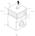
- Figure 1 is a perspective view of a household appliance according to a first embodiment of the present invention, showing the structure in its collapsed position;
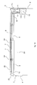
- Figure 2 is a perspective view of the household appliance according to a first embodiment of the present invention, showing the panel of the structure during a lifting phase;
- Figure 3 is a perspective view of the household appliance according to a first embodiment of the present invention, showing the structure in its extended position;
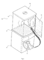
- Figure 4 is a perspective view of the household appliance according to a first embodiment of the present invention, showing the drying cabinet in operation;
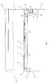
- Figure 5 is a side cross-sectional view of the household appliance shown in Figure 4;
- Figure 6 is a perspective view of a household appliance according to a second embodiment of the present invention, showing the arms of the clothes-horse in their first convergent position;
- Figure 7 is a perspective view of the household appliance according to a second embodiment of the present invention, showing the arms of the clothes-horse in rotation;
- Figure 8 is a perspective view of the household appliance according to a second embodiment of the present invention, showing the arms of the clothes-horse in their second divergent position;
- Figure 9 is a side cross-sectional view of the household appliance shown in Figure 8;
- Figure 10 is a side cross-sectional view of a household appliance according to a third embodiment of the present invention, showing the drawer-like structure in the inserted position;
- Figure 11 is a side cross-sectional view of the household appliance according to a third embodiment of the present invention, showing the drawer-like structure during an extraction phase;
- Figure 12 is a perspective view of the household appliance shown in figure 13 with the drawer-like structure extracted;
- Figure 13 is a side cross-sectional view of the household appliance according to a further embodiment of the present invention, showing the drawer-like structure during an extraction phase;
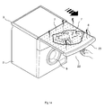
- Figure 14 is a perspective view of the household appliance shown in figure 13 with the drawer-like structure extracted;
- The household appliance, in particular for washing and/or drying clothes, according to the present invention, comprises an
outer casing 2 with aworktop 3 and afront panel 4 carrying operational input andsetting controls 5, a drum rotatably supported inside theouter casing 2 and adapted to be loaded with the items to be washed and/or dried, an opening for loading and unloading the items into and from the drum, and adoor 6 for closing said opening. - The household appliance comprises a
drying surface 8 having a plurality ofapertures 7, each one of which is fluidly connected with conveying means adapted to direct a flow of air through saidapertures 7 for drying garments that are placed over thedrying surface 8. - In particular, the
worktop 3 comprises thedrying surface 8, over which the garments to be dried are placed, and through the apertures orperforations 7 of which air is caused to flow so as to hit the garments placed thereon, thereby drying it. - These conveying means comprise at least an
air passage 9 adapted to convey the air up to theworktop 3 underneath thedrying surface 8, so that the air is then able to flow through theapertures 7 from the bottom upwards, as well as air circulating means 10 adapted to force a flow of air into and through theair passage 9. - In an advantageous manner, heating means 11 are provided to heat up the air that flows into the
air passage 9, so that it is appropriately heated-up air that eventually hits the garment to be dried. - The
air passage 9 extends horizontally along thedrying surface 8, so as to be able to supply air to eachsingle aperture 7 at the same time. Anend portion 12 of theair passage 9 is blind, i.e. sealed, whereas theother end portion 13 thereof is open and fluidly communicating with the air circulating means 10 to receive the flow of drying air thereinto. - Advantageously, the
drying surface 8 and theair passage 9 can be formed in theworktop 3 integrally. - The air circulating means 10 may for instance be comprised of at least a blower arranged inside the
outer casing 2 of the appliance and adapted to take in air from either the interior or the exterior of the household appliance to convey it into theair passage 9. - In particular, the blower is housed in a proper accommodation provided to this purpose inside the outer casing of the appliance.
- The conveying means further comprise a
communication duct 14 provided in the worktop and/or the outer casing to connect the air circulating means 10 with theair passage 9. - The heating means 11 may for instance be comprised of one or more electric heating elements arranged downstream from the air circulating means 10 and upstream of the
air passage 9. Preferably, the heating means 11 are housed inside thecommunication duct 14, upstream of theopen end portion 13 of theair passage 9. - As shown in Figure 1 to 5, the
worktop 3 comprises an extendable/collapsible structure 15 adapted to define a drying cabinet for accommodating garments to be dried over saiddrying surface 8, said dryingsurface 8 forming the bottom of such drying cabinet, so as to blow air directly into the drying cabinet itself. - The extendable/
collapsible structure 15 is comprised of apanel 16, which forms the ceiling, i.e. the top wall of the drying cabinet, anddeformable side members 17 that form the side walls of the drying cabinet. Thedeformable side members 17 connect thepanel 16 withdrying surface 8 so as to create the delimited inside compartment or cavity of the drying cabinet. As already hinted above, thedrying surface 8, as integrally provided on theworktop 3 of theouter casing 2 of the household appliance, forms the bottom surface or floor of the drying cabinet. - When the
structure 15 is not being used, thepanel 16 is lowered to seat neatly close to thedrying surface 8 of theworktop 3, while thedeformable side members 17 are folded up between thepanel 16 and thedrying surface 8. - For the drying cabinet to be used, the
panel 16 is then capable of being lifted from thedrying surface 8, thereby causing also thedeformable side members 17 to extend. Thepanel 16 is adapted to reach - at a preestablished height - a limiting lift-up position at which thedeformable side members 17 of thestructure 15, owing to them being fully extended, become rigid, thereby providing a stable drying cabinet. - At least one of the
deformable side members 17 is provided so as to enable the drying cabinet to be opened and closed and, therefore, the garments to be dried to be suitably arranged, e.g. hung, inside the same drying cabinet before closing it up for the drying process to take place thereinside. In particular, such deformable side member used to open/close the drying cabinet is made of a different material as compared with the other deformable side members, such as for example of plain cloth. - Advantageously, proper hangers with the clothes to be dried hung thereon may be hooked up to a plurality of receptacles provided at the
panel 16 for engagement therewith. Alternatively, the clothes to be dried may be laid flat upon proper rack-like or similar support members provided in the drying cabinet. - Advantageously, the
panel 16 further defines a handgrip provision, by means of which thepanel 16 can therefore be conveniently lifted. - The
structure 15 is collapsible, i.e. can be caused to collapse by simply lowering thepanel 16 onto thedrying surface 8, so that thedeformable side members 17 lose their rigidity and can be folded up into position between thepanel 16 and the worktop of the household appliance. - By switching on the air circulating means 10 and the heating means 11, hot air is blown into the extended drying cabinet through the
apertures 7 in thedrying surface 8. In this manner, the possibility is therefore given for a plurality of garments to be quickly and effectively dried at the same time. - In a further embodiment of the present invention, which is illustrated in Figures 6 to 9, the
worktop 3 comprises a kind of collapsible clothes-horse 18 for the garments to be dried to be laid flat thereupon over thedrying surface 8 at a certain distance from the latter. Advantageously, such clothes-horse 18 is comprised of a folding structure adapted to lay flat on thedrying surface 8 when the clothes-horse 18 is not in use. - Namely, the clothes-
horse 18 being described and discussed by way of example to illustrative purposes, comprises a pair ofarcuate arms 19 that are rotatably associated to theworktop 3, in a lateral position thereupon, and a plurality oflines 20 having their ends linked with, i.e. engaging saidarms 19. - The
arms 19 are adapted to rotate from a first position, in which they are convergent and lying flat on thedrying surface 8 along with thelines 20, to a second position, in which they are raised from thedrying surface 8 and mutually divergent so as to stretch out and tighten thelines 20. - In the first folded position, the
arms 19 and thelines 20 lie completely flat on thedrying surface 8, while protruding by just a few millimeters therefrom, so as to take up just a minimum of space. In the second outstretched position, thearms 19 and thelines 20 enable garments to be laid to dry at a short distance above the drying surface, while providing a greater surface area for placing large garments thereupon. - In a still further embodiment of the present invention, as illustrated in Figures 10 to 14, the
drying surface 8 is slidable in an accommodation orhousing 21 provided in theworktop 3 from a first position, in which the drying surface is contained, i.e. inserted within theaccommodation 21 in theworktop 3, to a second position in which thedrying surface 8 is extracted and extended horizontally out of theaccommodation 21 in theworktop 3 for garments to be dried to be supported thereupon. - The
drying surface 8 is in this case provided integrally on a drawer-like structure 22 adapted to slide within theaccommodation 21 along appropriate runner means. Such drawer-like structure 22 is internally hollow so as to integrally form theair passage 9 for conveying the flow of drying air under and along thedrying surface 8 - In the first position thereof, the drawer-
like structure 22 is fully inserted in theaccommodation 21, so that it is fully placed inside the worktop, wherein solely ahandgrip portion 23 provided on the front of the drawer-like structure 22 protrudes from theworktop 3 for enabling the same drawer-like structure 22 to be conveniently extracted when needed for use. - In the second position thereof, the drawer-
like structure 22 is extracted, i.e. pulled out from theaccommodation 21, so that the dryingsurface 8 comes to protrude horizontally from theworktop 3 on the front side thereof. The garments to be dried are then laid upon the dryingsurface 8 and, upon switching on theair circulating means 10 and the heating means 11, hot air starts to flow through theapertures 7 in the dryingsurface 8 so as to hit the garments laid thereupon and dry them. - The
accommodation 21 further defines a drying-medium conveying channel adapted to fluidly connect theair passage 9 of the drawer-like structure 22 with theair circulating means 10, when drawer-like structure 22 is extracted, i.e. pulled out from theaccommodation 21, in said second position. - The
worktop 3 may itself comprise a plurality ofapertures 24 fluidly connected with the air circulating means 10 so as to define asecond drying surface 25, so that both theslidable drying surface 8 of the drawer-like structure 22 and the dryingsurface 8 of the worktop can be used to dry either a plurality of garments at the same time or a single large-sized garment. Alternatively, the worktop can however be provided in the form of a conventional worktop, without any aperture. - The drying
surface 8 provided on the drawer-like structure 22 enables garments to be dried even when the surface of theworktop 3 is not directly accessible owing to encumbrances being present immediately above thesame worktop 3. - In alternative embodiments of the present invention the conveying means are provided outside the casing.
- In particular, for example, the
air circulating means 10 and thecommunication duct 14 are associated to the upper backward portion of the casing in proximity to and below the worktop projecting from the casing. - The above-described drying arrangements may be provided on a washing machine, a tumble dryer or a so-called washer-dryer, wherein it will be readily appreciated that a perforated worktop as described above may even be applied to top-loading appliances.
- It will however be also readily appreciated that a drying arrangement of the above described kind may be provided in the form of a self-standing, i.e. autonomous household appliance specially intended for drying delicate garments, which is designed to integrally comprise a perforated drying surface and air conveying means as described above.
- The household appliance comprises control means to enable the
air circulating means 10 and the heating means 11 to be switched on as required, as well as the different drying modes of the appliance to be properly selected. In this connection, it should in fact be noticed that different drying temperatures and different drying times may be required to most properly handle the various garments to be dried, depending, among other things, on the textile fibres which each single garment is made of. - Such control means are arranged on the
front panel 4 of the washing and/or drying machine or on a specific console provided on the self-standing appliance. - In another embodiment the control means are directly integrated on the drying
surface 8 of the washing and/or drying machine or on the worktop of the self-standing appliance. - It can therefore be conclusively stated that, with the arrangement according to the present invention, delicate textiles can be gently and effectively dried in a most convenient manner, without this implying any large energy usage, thereby doing away with the drawbacks cited as regard
EP 06 112 671.0 - Advantageously the household appliance according to the present invention can be used to warm the room where the appliance is located, in particular, for example, the bathroom. In fact, when no garment is present upon the worktop, hot and dry air is adapted to be discharged to the atmosphere through the
apertures 7 by means of the blower and the electric heating elements. For this purpose, control means are provided to operate theair circulating means 10 and the heating means 11 according to a specifically intended warm-up mode in order to heat up the air of the room where the appliance is located.
Claims (24)
- Household appliance comprising an outer casing (2) provided with a worktop (3), and at least a drying surface (8) having a plurality of apertures (7) fluidly connected with conveying means adapted to deliver a flow of air through said apertures (7) for drying garments placed over said drying surface (8), characterized in that said worktop (3) comprises an extendable/collapsible structure (15) adapted to define a drying cabinet for accommodating garments to be dried, said drying surface (8) forming the bottom of the drying cabinet so as to blow air directly into said drying cabinet.
- Household appliance according to claim 1, wherein said extendable/collapsible structure (15) is comprised of a panel (16), which forms the ceiling, i.e. the top wall of the drying cabinet, and deformable side members (17) that form the side walls of the drying cabinet, said deformable side members (17) connecting the panel (16) with the drying surface (8).
- Household appliance according to claim 1 or 2, wherein said drying surface (8) is integrally provided on the worktop (3) of the outer casing (2) to form the bottom surface of the drying cabinet.
- Household appliance according to claim 2, wherein said panel (16) is in a position in which it lies close upon the drying surface (8), and said deformable side members (17) are folded up between the panel (16) and the drying surface (8), when the structure (15) is not being used.
- Household appliance according to claim 2, wherein said panel (16) is capable of being brought to a raised position relative to drying surface (8) so as to cause the deformable side members (17) to extend, said panel (16) being adapted to reach up to a limiting lift-up position in which, owing to them being fully extended, the deformable side members (17) of the structure (15) become rigid, thereby forming said drying cabinet.
- Household appliance according to claim 2, wherein at least one of said deformable side members (17) is provided so as to enable the drying cabinet to be opened and closed and, therefore, the garments to be dried to be arranged thereinside and removed therefrom.
- Household appliance comprising an outer casing (2) provided with a worktop (3), and at least a drying surface (8) having a plurality of apertures (7) fluidly connected with conveying means adapted to deliver a flow of air through said apertures (7) for drying garments placed over said drying surface (8), characterized in that the worktop (3) comprises a clothes-horse (18) for laying out garments above the drying surface (8) at a certain distance therefrom.
- Household appliance according to claim 7, wherein said clothes-horse (18) is comprised of a foldable structure adapted to lie flat upon said drying surface (8) when the clothes-horse is not in use.
- Household appliance according to claim 8, wherein said clothes-horse (18) comprises a pair of arcuate arms (19) rotatably associated to the worktop (3) and a plurality of lines (20) having their ends engaging said arms (19).
- Household appliance according to claim 8, wherein said arms (19) are adapted to rotate from a first position, in which they are convergent relative to each other and lie flat on the drying surface (8) along with the lines (20), to a second position, in which they are raised from the drying surface (8) and divergent relative to each other, so as to stretch out and tighten the lines (20) and enable the garments to be dried to be supported thereupon.
- Household appliance comprising an outer casing (2) provided with a worktop (3), and at least a drying surface (8) having a plurality of apertures (7) fluidly connected with conveying means adapted to deliver a flow of air through said apertures (7) for drying garments placed over said drying surface (8), characterized in that said drying surface (8) is slidable within an accommodation (21) provided in said worktop (3) from a first position, in which the drying surface (8) is contained in the accommodation (21) of the worktop (3), to a second position, in which the drying surface (8) is extracted, i.e. pulled out horizontally from the accommodation (21) of the worktop (3) to support garments to be dried.
- Household appliance according to claim 11, wherein said drying surface (8) is provided integrally on a drawer-like structure (22) adapted to slide within the accommodation (21).
- Household appliance according to claim 12, wherein said drawer-like structure (22) is hollow internally so as to integrally form said conveying means for the hot drying air to be conveyed under and along the drying surface (8).
- Household appliance according to any of the preceding claims, wherein said conveying means comprise at least an air passage (9) adapted to convey the air up to and along the worktop (3) underneath the drying surface (8), so that the air is able to flow through the apertures (7) from the bottom upwards, and air circulating means (10) adapted to force a flow of air into and through the air passage (9).
- Household appliance according to any of the preceding claims, wherein heating means (11) are provided to heat up the air, so that it is properly heated-up air that eventually hits the garment to be dried.
- Household appliance according to any of the preceding claims, wherein said air passage (9) extends along the drying surface (8) and defines an open end portion (13) fluidly communicating with the air circulating means (10) to receive the flow of drying air thereinto.
- Household appliance according to any of the preceding claims, wherein said heating means (11) are arranged downstream from the air circulating means (10) and upstream of the air passage (9).
- Household appliance to any of the preceding claims 11 to 17, wherein said accommodation (21) defines a drying-medium channel adapted to fluidly connect the air passage (9) of the drawer-like structure (22) with the air circulating means (10), when said drawer-like structure (22) is in said second position.
- Household appliance according to any of the preceding claims 11 to 18, wherein said worktop (3) comprises a plurality of apertures (24) that fluidly communicate with the air circulating means (10) to define a second drying surface (25).
- Household appliance according to any of the preceding claims, wherein said air passage (9) is integrally formed in the worktop (3).
- Household appliance according to any of the preceding claims, comprising control means to enable the air circulating means (10) and the heating means (11) to be switched on and operated as required.
- Household appliance according to any of the preceding claims, wherein said control means are provided to enable different drying temperatures and different drying times to most properly handle the various garments to be dried, depending on the textile fibres which each single garment is made of.
- Household appliance according to any of the preceding claims, wherein said control means are provided to operate the air circulating means (10) and the heating means (11) according to a specifically intended warm-up mode in order to heat up the air of the room where the appliance is located.
- Household appliance according to any of the preceding claims, comprising a drum rotatably supported inside the outer casing (2) and adapted to be loaded with items to be washed and/or dried.
Priority Applications (6)
| Application Number | Priority Date | Filing Date | Title |
|---|---|---|---|
| ES06113737T ES2327669T3 (en) | 2006-05-09 | 2006-05-09 | APPLIANCES. |
| EP06113737A EP1854916B1 (en) | 2006-05-09 | 2006-05-09 | Household appliance |
| DE602006007815T DE602006007815D1 (en) | 2006-05-09 | 2006-05-09 | household appliance |
| PL06113737T PL1854916T3 (en) | 2006-05-09 | 2006-05-09 | Household appliance |
| PCT/EP2007/001406 WO2007128358A1 (en) | 2006-05-09 | 2007-02-19 | Household appliance |
| RU2008148330/12A RU2432424C2 (en) | 2006-05-09 | 2007-02-19 | Domestic appliance |
Applications Claiming Priority (1)
| Application Number | Priority Date | Filing Date | Title |
|---|---|---|---|
| EP06113737A EP1854916B1 (en) | 2006-05-09 | 2006-05-09 | Household appliance |
Publications (2)
| Publication Number | Publication Date |
|---|---|
| EP1854916A1 true EP1854916A1 (en) | 2007-11-14 |
| EP1854916B1 EP1854916B1 (en) | 2009-07-15 |
Family
ID=36982259
Family Applications (1)
| Application Number | Title | Priority Date | Filing Date |
|---|---|---|---|
| EP06113737A Active EP1854916B1 (en) | 2006-05-09 | 2006-05-09 | Household appliance |
Country Status (6)
| Country | Link |
|---|---|
| EP (1) | EP1854916B1 (en) |
| DE (1) | DE602006007815D1 (en) |
| ES (1) | ES2327669T3 (en) |
| PL (1) | PL1854916T3 (en) |
| RU (1) | RU2432424C2 (en) |
| WO (1) | WO2007128358A1 (en) |
Cited By (15)
| Publication number | Priority date | Publication date | Assignee | Title |
|---|---|---|---|---|
| EP2194184A1 (en) | 2008-12-04 | 2010-06-09 | Electrolux Home Products Corporation N.V. | Device for drying shoes exploiting a laundry drying household appliance |
| EP2196573A1 (en) | 2008-12-12 | 2010-06-16 | Electrolux Home Products N.V. | Household appliance with surface for steam treating laundry |
| EP2199453A1 (en) | 2008-12-17 | 2010-06-23 | Electrolux Home Products Corporation N.V. | A household appliance |
| EP2204487A1 (en) | 2008-12-30 | 2010-07-07 | Electrolux Home Products Corporation N.V. | A household appliance for drying garments |
| EP2270275A1 (en) | 2009-06-29 | 2011-01-05 | Electrolux Home Products Corporation N.V. | Appliance for drying laundry |
| US20140026433A1 (en) * | 2011-01-04 | 2014-01-30 | Electrolux Home Products Corporation N.V. | Appliance for drying laundry |
| EP3284856A1 (en) * | 2017-12-01 | 2018-02-21 | V-Zug AG | Drum and room air dryer with an assembly device |
| US20180187367A1 (en) * | 2016-12-29 | 2018-07-05 | Lg Electronics Inc. | Dual type drying machine |
| KR20180078082A (en) * | 2016-12-29 | 2018-07-09 | 엘지전자 주식회사 | Dual type dryer |
| CN110325680A (en) * | 2016-12-23 | 2019-10-11 | 三星电子株式会社 | Drying device and clothes treatment device including it |
| US10508384B2 (en) | 2009-06-29 | 2019-12-17 | Electrolux Home Products Corporation N.V. | Top of an appliance for drying laundry providing drying air recirculation and moisture condensation |
| US10519592B2 (en) | 2009-06-29 | 2019-12-31 | Electrolux Home Products Corporation N.V. | Appliance for drying laundry providing drying air recirculation and moisture condensation |
| EP3483333A4 (en) * | 2016-07-07 | 2020-01-22 | LG Electronics Inc. -1- | Clothes-handling apparatus |
| WO2020078304A1 (en) * | 2018-10-17 | 2020-04-23 | 青岛海尔洗衣机有限公司 | Clothes care device |
| EP4095309A3 (en) * | 2021-05-03 | 2023-03-01 | Whirlpool Corporation | Laundry appliance having laundry accessories |
Families Citing this family (1)
| Publication number | Priority date | Publication date | Assignee | Title |
|---|---|---|---|---|
| EP3467187B1 (en) | 2017-10-09 | 2021-12-22 | Whirlpool Corporation | Filter configured for being used in a machine for drying laundry and machine for drying laundry equipped with such a filter |
Citations (7)
| Publication number | Priority date | Publication date | Assignee | Title |
|---|---|---|---|---|
| US3905125A (en) * | 1973-03-06 | 1975-09-16 | Huebner Otto | Collapsible garment dryer |
| US4819341A (en) * | 1986-10-17 | 1989-04-11 | Donald Gayso | Dryer for permanent press fabrics |
| US5778573A (en) * | 1997-01-10 | 1998-07-14 | Whitney Designs, Inc. | Two-way swivel bracket with ironing board assembly |
| EP1146161A1 (en) * | 2000-04-10 | 2001-10-17 | Whirlpool Corporation | Accessory assembly for a clothes drum type dryer |
| EP1431442A1 (en) * | 2002-12-18 | 2004-06-23 | BSH Bosch und Siemens Hausgeräte GmbH | Device for drying and conditioning laundry in connection with a domestic laundry dryer |
| DE10318486B3 (en) * | 2003-04-16 | 2004-10-21 | Niewald, Lothar, Dipl.-Ing. | Collapsible clothes dryer comprises a fan for producing an air stream and a drying frame of determined width |
| US20050278983A1 (en) * | 2004-03-01 | 2005-12-22 | Maytag Corporation | Filter vent for drying cabinet |
-
2006
- 2006-05-09 ES ES06113737T patent/ES2327669T3/en active Active
- 2006-05-09 EP EP06113737A patent/EP1854916B1/en active Active
- 2006-05-09 DE DE602006007815T patent/DE602006007815D1/en active Active
- 2006-05-09 PL PL06113737T patent/PL1854916T3/en unknown
-
2007
- 2007-02-19 WO PCT/EP2007/001406 patent/WO2007128358A1/en active Application Filing
- 2007-02-19 RU RU2008148330/12A patent/RU2432424C2/en not_active IP Right Cessation
Patent Citations (7)
| Publication number | Priority date | Publication date | Assignee | Title |
|---|---|---|---|---|
| US3905125A (en) * | 1973-03-06 | 1975-09-16 | Huebner Otto | Collapsible garment dryer |
| US4819341A (en) * | 1986-10-17 | 1989-04-11 | Donald Gayso | Dryer for permanent press fabrics |
| US5778573A (en) * | 1997-01-10 | 1998-07-14 | Whitney Designs, Inc. | Two-way swivel bracket with ironing board assembly |
| EP1146161A1 (en) * | 2000-04-10 | 2001-10-17 | Whirlpool Corporation | Accessory assembly for a clothes drum type dryer |
| EP1431442A1 (en) * | 2002-12-18 | 2004-06-23 | BSH Bosch und Siemens Hausgeräte GmbH | Device for drying and conditioning laundry in connection with a domestic laundry dryer |
| DE10318486B3 (en) * | 2003-04-16 | 2004-10-21 | Niewald, Lothar, Dipl.-Ing. | Collapsible clothes dryer comprises a fan for producing an air stream and a drying frame of determined width |
| US20050278983A1 (en) * | 2004-03-01 | 2005-12-22 | Maytag Corporation | Filter vent for drying cabinet |
Cited By (26)
| Publication number | Priority date | Publication date | Assignee | Title |
|---|---|---|---|---|
| EP2194184A1 (en) | 2008-12-04 | 2010-06-09 | Electrolux Home Products Corporation N.V. | Device for drying shoes exploiting a laundry drying household appliance |
| EP2196573A1 (en) | 2008-12-12 | 2010-06-16 | Electrolux Home Products N.V. | Household appliance with surface for steam treating laundry |
| WO2010066426A1 (en) * | 2008-12-12 | 2010-06-17 | Electrolux Home Products Corporation N.V. | Household appliance with surface for steam treating laundry |
| EP2199453A1 (en) | 2008-12-17 | 2010-06-23 | Electrolux Home Products Corporation N.V. | A household appliance |
| WO2010069535A1 (en) * | 2008-12-17 | 2010-06-24 | Electrolux Home Products Corporation N.V. | A household appliance |
| US8739433B2 (en) | 2008-12-30 | 2014-06-03 | Electrolux Home Products Corporation N.V. | Household appliance for drying garments |
| EP2204487A1 (en) | 2008-12-30 | 2010-07-07 | Electrolux Home Products Corporation N.V. | A household appliance for drying garments |
| WO2010076005A1 (en) | 2008-12-30 | 2010-07-08 | Electrolux Home Products Corporation N.V. | A household appliance for drying garments |
| US10519592B2 (en) | 2009-06-29 | 2019-12-31 | Electrolux Home Products Corporation N.V. | Appliance for drying laundry providing drying air recirculation and moisture condensation |
| WO2011000762A1 (en) | 2009-06-29 | 2011-01-06 | Electrolux Home Products Corporation N.V. | Appliance for drying laundry |
| US10508384B2 (en) | 2009-06-29 | 2019-12-17 | Electrolux Home Products Corporation N.V. | Top of an appliance for drying laundry providing drying air recirculation and moisture condensation |
| EP2270275A1 (en) | 2009-06-29 | 2011-01-05 | Electrolux Home Products Corporation N.V. | Appliance for drying laundry |
| US9335095B2 (en) * | 2011-01-04 | 2016-05-10 | Electrolux Home Products Corporation N.V. | Appliance for drying laundry |
| US20140026433A1 (en) * | 2011-01-04 | 2014-01-30 | Electrolux Home Products Corporation N.V. | Appliance for drying laundry |
| EP3483333A4 (en) * | 2016-07-07 | 2020-01-22 | LG Electronics Inc. -1- | Clothes-handling apparatus |
| US11707542B2 (en) | 2016-07-07 | 2023-07-25 | Lg Electronics Inc. | Clothes-handling apparatus |
| US11021836B2 (en) | 2016-07-07 | 2021-06-01 | Lg Electronics Inc. | Clothes-handling apparatus |
| CN110325680B (en) * | 2016-12-23 | 2022-05-03 | 三星电子株式会社 | Drying device and clothes treatment equipment comprising same |
| CN110325680A (en) * | 2016-12-23 | 2019-10-11 | 三星电子株式会社 | Drying device and clothes treatment device including it |
| US20180187367A1 (en) * | 2016-12-29 | 2018-07-05 | Lg Electronics Inc. | Dual type drying machine |
| US10738412B2 (en) | 2016-12-29 | 2020-08-11 | Lg Electronics Inc. | Dual type drying machine |
| KR20180078082A (en) * | 2016-12-29 | 2018-07-09 | 엘지전자 주식회사 | Dual type dryer |
| WO2018124421A1 (en) * | 2016-12-29 | 2018-07-05 | 엘지전자 주식회사 | Dual type dryer |
| EP3284856A1 (en) * | 2017-12-01 | 2018-02-21 | V-Zug AG | Drum and room air dryer with an assembly device |
| WO2020078304A1 (en) * | 2018-10-17 | 2020-04-23 | 青岛海尔洗衣机有限公司 | Clothes care device |
| EP4095309A3 (en) * | 2021-05-03 | 2023-03-01 | Whirlpool Corporation | Laundry appliance having laundry accessories |
Also Published As
| Publication number | Publication date |
|---|---|
| RU2432424C2 (en) | 2011-10-27 |
| RU2008148330A (en) | 2010-06-20 |
| WO2007128358A1 (en) | 2007-11-15 |
| EP1854916B1 (en) | 2009-07-15 |
| PL1854916T3 (en) | 2009-12-31 |
| ES2327669T3 (en) | 2009-11-02 |
| DE602006007815D1 (en) | 2009-08-27 |
Similar Documents
| Publication | Publication Date | Title |
|---|---|---|
| EP1854916B1 (en) | Household appliance | |
| US9416484B2 (en) | Household appliance | |
| US10774462B2 (en) | Laundry treating appliance with separate container | |
| US6745496B2 (en) | Air-flow dryer and method | |
| US8733134B2 (en) | Auxiliary laundry treating machine and multiple treating system including the same | |
| KR100841308B1 (en) | laundry device | |
| US20090139037A1 (en) | Laundry device and method for controlling the same | |
| US8819956B2 (en) | Clothes dryer | |
| US20120055039A1 (en) | Drying and warming appliance | |
| KR20110130091A (en) | Laundry machine | |
| KR20010113436A (en) | Steam ironing apparatus | |
| US11414809B2 (en) | Drying rack for a laundry treating appliance | |
| KR20100096388A (en) | Dryer | |
| EP2196573B1 (en) | Household appliance with surface for steam treating laundry | |
| KR101708693B1 (en) | Fabric treating apparatus and fabric treating system | |
| KR100595239B1 (en) | complex type dryer having lathe which can be folded | |
| US20130180123A1 (en) | Appliance having a drying rack | |
| US20130174434A1 (en) | Drying rack for use with a dryer appliance | |
| KR102344059B1 (en) | Washing machine | |
| CN112301701A (en) | Drying device | |
| CN220413830U (en) | Multi-gear automatic clothes dryer | |
| KR101708694B1 (en) | Fabric treating apparatus | |
| US20220349111A1 (en) | Laundry appliance having laundry accessories | |
| KR20060095406A (en) | Washing machine | |
| KR200431764Y1 (en) | The wash system which is composed of a furniture form |
Legal Events
| Date | Code | Title | Description |
|---|---|---|---|
| PUAI | Public reference made under article 153(3) epc to a published international application that has entered the european phase |
Free format text: ORIGINAL CODE: 0009012 |
|
| 17P | Request for examination filed |
Effective date: 20070427 |
|
| AK | Designated contracting states |
Kind code of ref document: A1 Designated state(s): AT BE BG CH CY CZ DE DK EE ES FI FR GB GR HU IE IS IT LI LT LU LV MC NL PL PT RO SE SI SK TR |
|
| AX | Request for extension of the european patent |
Extension state: AL BA HR MK YU |
|
| 17Q | First examination report despatched |
Effective date: 20071221 |
|
| AKX | Designation fees paid |
Designated state(s): AT BE BG CH CY CZ DE DK EE ES FI FR GB GR HU IE IS IT LI LT LU LV MC NL PL PT RO SE SI SK TR |
|
| GRAP | Despatch of communication of intention to grant a patent |
Free format text: ORIGINAL CODE: EPIDOSNIGR1 |
|
| GRAS | Grant fee paid |
Free format text: ORIGINAL CODE: EPIDOSNIGR3 |
|
| GRAA | (expected) grant |
Free format text: ORIGINAL CODE: 0009210 |
|
| AK | Designated contracting states |
Kind code of ref document: B1 Designated state(s): AT BE BG CH CY CZ DE DK EE ES FI FR GB GR HU IE IS IT LI LT LU LV MC NL PL PT RO SE SI SK TR |
|
| REG | Reference to a national code |
Ref country code: CH Ref legal event code: EP Ref country code: GB Ref legal event code: FG4D |
|
| REG | Reference to a national code |
Ref country code: IE Ref legal event code: FG4D |
|
| REF | Corresponds to: |
Ref document number: 602006007815 Country of ref document: DE Date of ref document: 20090827 Kind code of ref document: P |
|
| REG | Reference to a national code |
Ref country code: ES Ref legal event code: FG2A Ref document number: 2327669 Country of ref document: ES Kind code of ref document: T3 |
|
| REG | Reference to a national code |
Ref country code: PL Ref legal event code: T3 |
|
| NLV1 | Nl: lapsed or annulled due to failure to fulfill the requirements of art. 29p and 29m of the patents act | ||
| PG25 | Lapsed in a contracting state [announced via postgrant information from national office to epo] |
Ref country code: IS Free format text: LAPSE BECAUSE OF FAILURE TO SUBMIT A TRANSLATION OF THE DESCRIPTION OR TO PAY THE FEE WITHIN THE PRESCRIBED TIME-LIMIT Effective date: 20091115 Ref country code: FI Free format text: LAPSE BECAUSE OF FAILURE TO SUBMIT A TRANSLATION OF THE DESCRIPTION OR TO PAY THE FEE WITHIN THE PRESCRIBED TIME-LIMIT Effective date: 20090715 Ref country code: AT Free format text: LAPSE BECAUSE OF FAILURE TO SUBMIT A TRANSLATION OF THE DESCRIPTION OR TO PAY THE FEE WITHIN THE PRESCRIBED TIME-LIMIT Effective date: 20090715 Ref country code: SE Free format text: LAPSE BECAUSE OF FAILURE TO SUBMIT A TRANSLATION OF THE DESCRIPTION OR TO PAY THE FEE WITHIN THE PRESCRIBED TIME-LIMIT Effective date: 20090715 Ref country code: LT Free format text: LAPSE BECAUSE OF FAILURE TO SUBMIT A TRANSLATION OF THE DESCRIPTION OR TO PAY THE FEE WITHIN THE PRESCRIBED TIME-LIMIT Effective date: 20090715 |
|
| PG25 | Lapsed in a contracting state [announced via postgrant information from national office to epo] |
Ref country code: NL Free format text: LAPSE BECAUSE OF FAILURE TO SUBMIT A TRANSLATION OF THE DESCRIPTION OR TO PAY THE FEE WITHIN THE PRESCRIBED TIME-LIMIT Effective date: 20090715 Ref country code: SI Free format text: LAPSE BECAUSE OF FAILURE TO SUBMIT A TRANSLATION OF THE DESCRIPTION OR TO PAY THE FEE WITHIN THE PRESCRIBED TIME-LIMIT Effective date: 20090715 Ref country code: LV Free format text: LAPSE BECAUSE OF FAILURE TO SUBMIT A TRANSLATION OF THE DESCRIPTION OR TO PAY THE FEE WITHIN THE PRESCRIBED TIME-LIMIT Effective date: 20090715 |
|
| PG25 | Lapsed in a contracting state [announced via postgrant information from national office to epo] |
Ref country code: PT Free format text: LAPSE BECAUSE OF FAILURE TO SUBMIT A TRANSLATION OF THE DESCRIPTION OR TO PAY THE FEE WITHIN THE PRESCRIBED TIME-LIMIT Effective date: 20091115 Ref country code: BG Free format text: LAPSE BECAUSE OF FAILURE TO SUBMIT A TRANSLATION OF THE DESCRIPTION OR TO PAY THE FEE WITHIN THE PRESCRIBED TIME-LIMIT Effective date: 20091015 |
|
| PG25 | Lapsed in a contracting state [announced via postgrant information from national office to epo] |
Ref country code: CZ Free format text: LAPSE BECAUSE OF FAILURE TO SUBMIT A TRANSLATION OF THE DESCRIPTION OR TO PAY THE FEE WITHIN THE PRESCRIBED TIME-LIMIT Effective date: 20090715 Ref country code: DK Free format text: LAPSE BECAUSE OF FAILURE TO SUBMIT A TRANSLATION OF THE DESCRIPTION OR TO PAY THE FEE WITHIN THE PRESCRIBED TIME-LIMIT Effective date: 20090715 Ref country code: RO Free format text: LAPSE BECAUSE OF FAILURE TO SUBMIT A TRANSLATION OF THE DESCRIPTION OR TO PAY THE FEE WITHIN THE PRESCRIBED TIME-LIMIT Effective date: 20090715 Ref country code: EE Free format text: LAPSE BECAUSE OF FAILURE TO SUBMIT A TRANSLATION OF THE DESCRIPTION OR TO PAY THE FEE WITHIN THE PRESCRIBED TIME-LIMIT Effective date: 20090715 |
|
| PLBE | No opposition filed within time limit |
Free format text: ORIGINAL CODE: 0009261 |
|
| STAA | Information on the status of an ep patent application or granted ep patent |
Free format text: STATUS: NO OPPOSITION FILED WITHIN TIME LIMIT |
|
| PG25 | Lapsed in a contracting state [announced via postgrant information from national office to epo] |
Ref country code: SK Free format text: LAPSE BECAUSE OF FAILURE TO SUBMIT A TRANSLATION OF THE DESCRIPTION OR TO PAY THE FEE WITHIN THE PRESCRIBED TIME-LIMIT Effective date: 20090715 Ref country code: BE Free format text: LAPSE BECAUSE OF FAILURE TO SUBMIT A TRANSLATION OF THE DESCRIPTION OR TO PAY THE FEE WITHIN THE PRESCRIBED TIME-LIMIT Effective date: 20090715 |
|
| 26N | No opposition filed |
Effective date: 20100416 |
|
| PG25 | Lapsed in a contracting state [announced via postgrant information from national office to epo] |
Ref country code: GR Free format text: LAPSE BECAUSE OF FAILURE TO SUBMIT A TRANSLATION OF THE DESCRIPTION OR TO PAY THE FEE WITHIN THE PRESCRIBED TIME-LIMIT Effective date: 20091016 |
|
| PG25 | Lapsed in a contracting state [announced via postgrant information from national office to epo] |
Ref country code: MC Free format text: LAPSE BECAUSE OF NON-PAYMENT OF DUE FEES Effective date: 20100531 |
|
| REG | Reference to a national code |
Ref country code: CH Ref legal event code: PL |
|
| PG25 | Lapsed in a contracting state [announced via postgrant information from national office to epo] |
Ref country code: LI Free format text: LAPSE BECAUSE OF NON-PAYMENT OF DUE FEES Effective date: 20100531 Ref country code: CH Free format text: LAPSE BECAUSE OF NON-PAYMENT OF DUE FEES Effective date: 20100531 |
|
| PG25 | Lapsed in a contracting state [announced via postgrant information from national office to epo] |
Ref country code: IE Free format text: LAPSE BECAUSE OF NON-PAYMENT OF DUE FEES Effective date: 20100509 |
|
| PG25 | Lapsed in a contracting state [announced via postgrant information from national office to epo] |
Ref country code: CY Free format text: LAPSE BECAUSE OF FAILURE TO SUBMIT A TRANSLATION OF THE DESCRIPTION OR TO PAY THE FEE WITHIN THE PRESCRIBED TIME-LIMIT Effective date: 20090715 |
|
| PG25 | Lapsed in a contracting state [announced via postgrant information from national office to epo] |
Ref country code: LU Free format text: LAPSE BECAUSE OF NON-PAYMENT OF DUE FEES Effective date: 20100509 Ref country code: HU Free format text: LAPSE BECAUSE OF FAILURE TO SUBMIT A TRANSLATION OF THE DESCRIPTION OR TO PAY THE FEE WITHIN THE PRESCRIBED TIME-LIMIT Effective date: 20100116 |
|
| PG25 | Lapsed in a contracting state [announced via postgrant information from national office to epo] |
Ref country code: TR Free format text: LAPSE BECAUSE OF FAILURE TO SUBMIT A TRANSLATION OF THE DESCRIPTION OR TO PAY THE FEE WITHIN THE PRESCRIBED TIME-LIMIT Effective date: 20090715 |
|
| PGFP | Annual fee paid to national office [announced via postgrant information from national office to epo] |
Ref country code: ES Payment date: 20120525 Year of fee payment: 7 |
|
| PGFP | Annual fee paid to national office [announced via postgrant information from national office to epo] |
Ref country code: PL Payment date: 20130424 Year of fee payment: 8 |
|
| REG | Reference to a national code |
Ref country code: ES Ref legal event code: FD2A Effective date: 20150731 |
|
| PG25 | Lapsed in a contracting state [announced via postgrant information from national office to epo] |
Ref country code: PL Free format text: LAPSE BECAUSE OF NON-PAYMENT OF DUE FEES Effective date: 20140509 |
|
| REG | Reference to a national code |
Ref country code: PL Ref legal event code: LAPE |
|
| PG25 | Lapsed in a contracting state [announced via postgrant information from national office to epo] |
Ref country code: ES Free format text: LAPSE BECAUSE OF NON-PAYMENT OF DUE FEES Effective date: 20140510 |
|
| REG | Reference to a national code |
Ref country code: FR Ref legal event code: PLFP Year of fee payment: 11 |
|
| REG | Reference to a national code |
Ref country code: FR Ref legal event code: PLFP Year of fee payment: 12 |
|
| REG | Reference to a national code |
Ref country code: FR Ref legal event code: PLFP Year of fee payment: 13 |
|
| PGFP | Annual fee paid to national office [announced via postgrant information from national office to epo] |
Ref country code: FR Payment date: 20190523 Year of fee payment: 14 |
|
| PGFP | Annual fee paid to national office [announced via postgrant information from national office to epo] |
Ref country code: GB Payment date: 20190521 Year of fee payment: 14 |
|
| GBPC | Gb: european patent ceased through non-payment of renewal fee |
Effective date: 20200509 |
|
| PG25 | Lapsed in a contracting state [announced via postgrant information from national office to epo] |
Ref country code: GB Free format text: LAPSE BECAUSE OF NON-PAYMENT OF DUE FEES Effective date: 20200509 Ref country code: FR Free format text: LAPSE BECAUSE OF NON-PAYMENT OF DUE FEES Effective date: 20200531 |
|
| PGFP | Annual fee paid to national office [announced via postgrant information from national office to epo] |
Ref country code: IT Payment date: 20220524 Year of fee payment: 17 Ref country code: DE Payment date: 20220519 Year of fee payment: 17 |
|
| REG | Reference to a national code |
Ref country code: DE Ref legal event code: R119 Ref document number: 602006007815 Country of ref document: DE |