EP1850743B1 - Methods and apparatus for measuring the internal structure of an object - Google Patents
Methods and apparatus for measuring the internal structure of an object Download PDFInfo
- Publication number
- EP1850743B1 EP1850743B1 EP06704227A EP06704227A EP1850743B1 EP 1850743 B1 EP1850743 B1 EP 1850743B1 EP 06704227 A EP06704227 A EP 06704227A EP 06704227 A EP06704227 A EP 06704227A EP 1850743 B1 EP1850743 B1 EP 1850743B1
- Authority
- EP
- European Patent Office
- Prior art keywords
- output signals
- wave energy
- subset
- signal
- transmitter
- Prior art date
- Legal status (The legal status is an assumption and is not a legal conclusion. Google has not performed a legal analysis and makes no representation as to the accuracy of the status listed.)
- Not-in-force
Links
- 238000000034 method Methods 0.000 title claims description 43
- 210000000481 breast Anatomy 0.000 claims description 28
- 230000000694 effects Effects 0.000 claims description 9
- 241001465754 Metazoa Species 0.000 claims description 2
- 239000010410 layer Substances 0.000 description 35
- 206010028980 Neoplasm Diseases 0.000 description 17
- 238000001514 detection method Methods 0.000 description 13
- 230000003667 anti-reflective effect Effects 0.000 description 12
- 230000000903 blocking effect Effects 0.000 description 12
- 239000000463 material Substances 0.000 description 10
- 230000008878 coupling Effects 0.000 description 9
- 238000010168 coupling process Methods 0.000 description 9
- 238000005859 coupling reaction Methods 0.000 description 9
- 206010006187 Breast cancer Diseases 0.000 description 8
- 208000026310 Breast neoplasm Diseases 0.000 description 8
- 238000004458 analytical method Methods 0.000 description 7
- 238000003384 imaging method Methods 0.000 description 7
- 230000009467 reduction Effects 0.000 description 6
- 239000004411 aluminium Substances 0.000 description 5
- 229910052782 aluminium Inorganic materials 0.000 description 5
- XAGFODPZIPBFFR-UHFFFAOYSA-N aluminium Chemical compound [Al] XAGFODPZIPBFFR-UHFFFAOYSA-N 0.000 description 5
- 230000005540 biological transmission Effects 0.000 description 5
- 238000012216 screening Methods 0.000 description 5
- 238000013461 design Methods 0.000 description 4
- 238000012545 processing Methods 0.000 description 4
- 239000011347 resin Substances 0.000 description 4
- 229920005989 resin Polymers 0.000 description 4
- 239000000758 substrate Substances 0.000 description 4
- XLYOFNOQVPJJNP-UHFFFAOYSA-N water Substances O XLYOFNOQVPJJNP-UHFFFAOYSA-N 0.000 description 4
- 239000011358 absorbing material Substances 0.000 description 3
- 238000013459 approach Methods 0.000 description 3
- 238000002592 echocardiography Methods 0.000 description 3
- 238000009607 mammography Methods 0.000 description 3
- 201000011510 cancer Diseases 0.000 description 2
- 238000005094 computer simulation Methods 0.000 description 2
- 230000001934 delay Effects 0.000 description 2
- 230000001066 destructive effect Effects 0.000 description 2
- 239000007788 liquid Substances 0.000 description 2
- 230000008569 process Effects 0.000 description 2
- 230000005855 radiation Effects 0.000 description 2
- 230000004044 response Effects 0.000 description 2
- 238000002604 ultrasonography Methods 0.000 description 2
- 238000012935 Averaging Methods 0.000 description 1
- 238000004026 adhesive bonding Methods 0.000 description 1
- 230000003321 amplification Effects 0.000 description 1
- 238000003491 array Methods 0.000 description 1
- 239000011248 coating agent Substances 0.000 description 1
- 238000000576 coating method Methods 0.000 description 1
- 230000006835 compression Effects 0.000 description 1
- 238000007906 compression Methods 0.000 description 1
- 230000001627 detrimental effect Effects 0.000 description 1
- 239000000839 emulsion Substances 0.000 description 1
- 238000002474 experimental method Methods 0.000 description 1
- 230000002349 favourable effect Effects 0.000 description 1
- 230000010354 integration Effects 0.000 description 1
- 229940057995 liquid paraffin Drugs 0.000 description 1
- 230000003211 malignant effect Effects 0.000 description 1
- 239000011159 matrix material Substances 0.000 description 1
- 230000007246 mechanism Effects 0.000 description 1
- 229910052751 metal Inorganic materials 0.000 description 1
- 239000002184 metal Substances 0.000 description 1
- 238000003199 nucleic acid amplification method Methods 0.000 description 1
- 238000003672 processing method Methods 0.000 description 1
- 238000002310 reflectometry Methods 0.000 description 1
- 230000035945 sensitivity Effects 0.000 description 1
- 238000004088 simulation Methods 0.000 description 1
- 239000002356 single layer Substances 0.000 description 1
- 238000003466 welding Methods 0.000 description 1
Images


Classifications
-
- A—HUMAN NECESSITIES
- A61—MEDICAL OR VETERINARY SCIENCE; HYGIENE
- A61B—DIAGNOSIS; SURGERY; IDENTIFICATION
- A61B5/00—Measuring for diagnostic purposes; Identification of persons
- A61B5/05—Detecting, measuring or recording for diagnosis by means of electric currents or magnetic fields; Measuring using microwaves or radio waves
- A61B5/0507—Detecting, measuring or recording for diagnosis by means of electric currents or magnetic fields; Measuring using microwaves or radio waves using microwaves or terahertz waves
-
- A—HUMAN NECESSITIES
- A61—MEDICAL OR VETERINARY SCIENCE; HYGIENE
- A61B—DIAGNOSIS; SURGERY; IDENTIFICATION
- A61B5/00—Measuring for diagnostic purposes; Identification of persons
- A61B5/05—Detecting, measuring or recording for diagnosis by means of electric currents or magnetic fields; Measuring using microwaves or radio waves
-
- A—HUMAN NECESSITIES
- A61—MEDICAL OR VETERINARY SCIENCE; HYGIENE
- A61B—DIAGNOSIS; SURGERY; IDENTIFICATION
- A61B2562/00—Details of sensors; Constructional details of sensor housings or probes; Accessories for sensors
- A61B2562/14—Coupling media or elements to improve sensor contact with skin or tissue
- A61B2562/143—Coupling media or elements to improve sensor contact with skin or tissue for coupling microwaves
Definitions
- the present invention relates to a method and apparatus for measuring the internal structure of an object, such as a human breast.
- Breast cancer is the most common cancer in woman - in the UK, nearly 1 in 3 of all cancers in women occur in the breast, with a lifetime risk of 1 in 9 - see http://www.breastcancercare.org.uk/Breastcancer/Breastcancerfactsandstatistics.
- X-ray mammography is considered the most effective technique. See M. Brown, F. Houn, E. Sickles and L. Kessler, Screening mammography in community practice, Amer. J. Roentgen, vol. 165, pp. 1373-1377, Dec. 1995 .
- this technique suffers from relatively high false negative and positive detection rates, involves uncomfortable compression of the breast (see P. T. Huynh, A.
- Microwave radar-based detection of breast cancer is a non-ionising alternative that is being studied by a number of groups world-wide. See for example Xu Li and S. C. Hagness, A confocal microwave imaging algorithm for breast cancer detection, IEEE Microwave & Wireless Components Lett., vol.11, pp. 130-2, Mar. 2001 ; E. C. Fear and M. A. Stuchly, Microwave system for breast tumour detection, IEEE Microwave & Guided Wave Lett., vol. 9, pp 470-2, Nov. 1999 ; and P. M. Meaney, M. W. Fanning, D. Li, S. P. Poplack and K. D. Paulsen, Clinical prototype for active microwave imaging of the breast, IEEE Trans.
- Microwave attenuation in normal breast tissue is less than 4 dB/cm up to 10GHz (see S. C. Hagness, A. Taflove, and J. E. Bridges, Two-dimensional FDTD analysis of a pulsed microwave confocal system for breast cancer detection: fixed-focus and antenna-array sensors, IEEE Trans. on Biomed. Eng., vol. 45, pp. 1470-9, Dec. 1998 ) and this frequency range should permit sufficiently good spatial resolution after focusing.
- a microwave radar technique employing a Real Aperture Synthetically Organised Radar detection method originally developed for land mine detection is described in R. Benjamin, I. J. Craddock, G. S. Hilton, S. Litobarski, E. McCutcheon, R. Nilavalan, G. N. Crisp, Microwave detection of buried mines using non-contact, synthetic near-field focusing. IEE Proceedings: Radar, Sonar & Navigation, vol. 148, pp. 233-40, Aug. 2001 ; and in R. Benjamin, Post-Reception Focusing in Remote Detection Systems, US patent US-A-5,920,285 .
- WO 03/009753 discloses a method of measuring the internal structure of an object having an antenna array wherein one antenna is transmitting and several antennas receive in multiple receive channels.
- the skin artifact is removed by a method by which the skin artifact at each antenna may be estimated as a filtered combination of the signal at all other antennas.
- the signals from each of the other antennas are provided to FIR filters, the outputs of which are summed and subtracted from the signal from the particular antenna after a delay.
- a first aspect of the invention provides a method of measuring the internal structure of an object according to claim 9.
- the first aspect of the invention provides a processing method to remove surface reflection artifacts. High resolution is achieved by operating over a range of frequencies.
- step c) may be performed for only one subset. However, in general step c) will be performed a plurality of times, each instance relating to a different subset of output signals.
- the number of output signals in the subset may be equal to the total number of output signals generated by the receivers. However, in most cases the number of output signals in he subset is smaller than the total number of output signals generated by the receivers.
- the transmitters are typically microwave antennas or ultrasound transducers.
- the antennas/transducers are energized sequentially so as to transmit a series of wave pulses onto the object, as described in US-A-5,920,285 .
- Any antenna/transducer not acting as a transmitter acts as a receiver (reception by the transmitting antenna could also be included, but this is not preferred).
- only one transmitter can be transmitting at any one time, and each pulse contains frequency components spanning a range of frequencies.
- each transmitter may transmit a sinusoidal signal whose frequency is varied over a range.
- each transmitter transmits a unique encoded signal, enabling more than one transmitter to be energised at the same time.
- step ii) includes selecting one of the output signals in the subset as a calibration signal, for instance by selecting the signal which results in the smallest integral of the square difference between this signal and one other member of the subset of output signals.
- the calibration signal is then subtracted from the one other member in step iii). In general this process will be repeated for each member of the subset, resulting in a different calibration signal for each member of the subset.
- step ii) includes calculating an average of the subset of output signals, which may be a weighted average. This average calibration signal is then subtracted from each member of the subset.
- the first aspect of the invention requires relatively broadband signal processing. Therefore typically the calibration signal contains frequency components spanning a range having a width which is greater than 50% of the centre-frequency. In a microwave implementation of the imaging system this would imply typically a width greater than 1 GHz and most preferably greater than 4 GHz.
- the first aspect of the invention also provides apparatus for measuring the internal structure of an object according to claim 15.
- the apparatus includes
- the blocking member is positioned so as to partially or fully block reflected energy, and hence reduce reflected signal artifacts.
- the blocking member includes a screening material which does not allow waves to pass through.
- the screening material will be a metal such as aluminium.
- the blocking member may include an attenuating material which absorbs waves.
- an attenuating material is provided as a coating on a substrate of screening material.
- the transmitter and receiver comprise an array of antennas, and a blocking member is positioned between each pair of adjacent antennas in the array.
- the blocking member may be a perforated mesh, but preferably is in the form of a continuous screen.
- the method may include the steps of:
- the apparatus includes
- the anti-reflective layer lies in the path between the transmitter and the receiver via the object, and is in contact or in very close proximity to the surface of the object.
- the anti-reflection layer is designed in order that, when a wave is incident upon it, the reflected wave is similar in amplitude, but opposite in phase, to the one from the surface of the object so as to result in destructive interference. This is accomplished by tailoring the thickness of the layer, by giving it a thickness of one quarter wavelength at the given refractive index and operating frequency f .
- the anti-reflective layer includes a resin-based material, which may be water-loaded and/or aluminium-loaded.
- the anti-reflective layer may have a curved surface, for instance shaped to conform to the contour of a human breast.
- the transmitter may transmit at a single frequency only, but preferably the transmitter is configured to transmit wave energy over a range of frequencies including the frequenc f .
- the anti-reflection layer consists of a single layer of material.
- a multi-layer structure could also be envisaged.
- the total thickness of the multi-layer structure may be equal to or greater than ⁇ /4, and one or more of the layers within the multi-layer structure may have a thickness ⁇ /4.
- a multi-layer structure may give the ability to achieve better performance over a range of angles of incidence and a range of frequencies.
- the method may include
- the material of the anti-reflective layer is typically chosen to have an intermediate permittivity value. That is: ⁇ 2 lies between ⁇ 1 and ⁇ 3 .
- the anti-reflective layer may at least partially support the weight of the object.
- a second aspect of the invention provides a method of measuring the internal structure of an object according to claim 1.
- the second aspect of the invention reduces signal artefacts present in data associated with a desired point in the object, instead of acting directly on the output signals.
- the focusing step time- or phase-aligns the output signals, and optionally the focusing step may also apply amplitude weighting factors to the output signals.
- the additional points are selected to be in symmetrically equivalent positions in relation to the transmitters and receivers.
- the data associated with the desired point may be a time varying focused signal, or a scalar quantity (such as energy) associated with the desired point.
- the additional data may be a time varying focused signal, or a scalar quantity associated with an additional point.
- the second aspect of the invention also provides apparatus according to claim 8.
- the methods of the first and second aspects of the invention may be performed in any application in which signal artefacts caused by reflections from a surface are present.
- the object may be an area of land being surveyed to detect pipes or other buried objects.
- the object may be part of a built structure being surveyed for faults.
- the object is part of a human or animal body, such as a breast.
- the wave energy may be ultrasound, but is more typically electromagnetic wave energy, preferably in the microwave region with a frequency higher than 1 GHz and preferably higher than 4GHz.
- each transmitter is a stacked slot-fed patch antenna including a first patch, a second patch, and a ground plane including a slot for coupling wave energy into the first and second patches.
- a real aperture synthetically organised radar for breast cancer detection shown in Figure 1 operates by employing an array 2 of N antennas (e.g. 3 ) close to, or in contact with, the breast 1 . Each antenna in turn transmits a pulse and the received signal y i ( t ) at each of the other antennas is recorded.
- the pulse generator 8 and the detector 9 may be time-shared, by means of a switching matrix 5 as shown in Figure 1 , as may any transmit or receive path amplification ( 6 , 7 ).
- the recorded data is then synthetically focussed at any point of interest in the volume beneath this antenna array by time-aligning the signals y i ( t ), using the estimated propagation time T i from the transmit antenna to the receive antenna via any point of interest in the medium.
- w i are weighting factors that are applied to compensate for differences in the predicted attenuation between the round-trip paths between transmit and receive antennas via the point of interest, and/or to apply various optimisation criteria.
- FIG. 2 shows the stacked patch configuration employed for the breast imaging application.
- the chief components of the signals collected at the antenna elements are mutual coupling between the antennas, reflections from skin and the tumour echo.
- the direct antenna couplings will not significantly interfere with the tumour echo as they occur earlier in time.
- the large signal artefacts caused by reflections from the skin however pose a significant challenge since they tend to mask the reflections from tumours close to skin, despite the benefits of the radar method described herein. Techniques to mitigate the skin reflections are considered in the following sections.
- N element flat array will collect N ( N -1)/2 distinct signals arising from transmission on one antenna and reception on another. Among these paths, a number of sets of similar paths exist with approximately the same mutual coupling and skin reflections.
- any immediately adjacent pair of antennas within the array will observe similar amplitude and phase delays for the skin reflection.
- any next-neighbour pairing of transmit and receive antennas will observe similar amplitude and phase delays for the skin reflection 20 .
- the contribution 21 arising from any tumour 19 will however not be the same.
- Figure 3 illustrates the principle in the simplified scenario of a linear array adjacent to a flat skin surface
- the same concept may be extended to two dimensional arrays that conform to a curved surface, such as the breast (see Figure 4 ).
- the signals from similar paths may be processed by either of two alternative variants, as follows:
- the signals may be divided into segments in the time domain (each segment corresponding to a particular feature of the response, arising from a particular physical feature that results in coupling between the transmit and receiver antennas) and method (a) or (b) may then be applied to each segment at a time.
- N element array will collect N ( N -1)/2 distinct signals arising from transmission on one antenna and reception on another.
- the process of time-alignment and scaling in equation (1a) yields a focussed signal v 1 ( t ) corresponding to that point A .
- a calibration signal may then be generated from this subset of focused signals ( ⁇ 1 ( t ), ⁇ 2 ( t ), ⁇ 3 ( t ), ⁇ 4 ( t )) and this may then be subtracted from ⁇ 1 ( t ). In this way skin reflection and mutual couplings will be much reduced.
- the calibration signal may be formed, for example, by
- the calibration signal may be subtracted from ⁇ 1 ( t ) directly and the signal energy associated with this point calculated using e.g. equation (1b) or (1c).
- scalar energy values may first be computed for all of ( ⁇ 1 ( t ), ⁇ 2 ( t ) , ⁇ 3 ( t ), ⁇ 4 ( t )), and the subtraction then performed using these scalar energy values rather than the focused signals themselves.
- the screens are thin aluminium sheets with a thin layer of radar absorbing material on both sides to reduce multiple bounces and resonance effects.
- Various radar absorbing materials are available, and suitable products include Emerson & Cuming ECCOSORB FGM-40 (1mm thickness), ECCOSORB BSR (0.25mm, 0.5mm thickness) and ECCOSORB FDS (0.75mm thickness).
- Alternative absorbing materials could be employed, including water-loaded resins.
- the screens may be attached to the antenna support structure in a number of ways, such as gluing, bolting or welding.
- tumour to skin power ratios are given in Table 1 (the signal from the tumour can be calculated exactly using a background subtraction technique) - these can be seen to yield a 20dB reduction in the power of the skin reflection relative to the signal from the tumour.
- skin echoes 20 arise from the three layered structure comprising the matching liquid 22 (with assumed relative permittivity ⁇ 1 ), skin 24 (with assumed relative permittivity ⁇ 3 ) and the breast tissue 1 .
- the total echo comprises reflections from the two interfaces and the multiple bounces between these interfaces.
- the largest echo is a result of the single reflection from the upper face of the skin. This echo may be reduced by introducing an Anti-Reflection (AR) layer 25 next to the skin, as shown in Figure 6 .
- AR Anti-Reflection
- the thickness of the layer was of the order of 3mm (approximately ⁇ /4 at the mid-point frequency of 6GHz).
- the reflectivities of the skin phantom with the antireflection layer, and of a layer of skin phantom alone, were measured in a bath of breast tissue phantom medium using a network analyser.
- the antireflection layer yielded a reduction of over 10dB in the reflected signal from the skin across the frequency range 4.5GHz to 7GHz. Even outside of this frequency range the performance was generally better with the AR layer present.
- the patient In practice the patient is envisaged as lying in a prone position and for comfort as well as experimental precision, it is envisaged that the breast will be supported by a gently curved shell, probably created from a rigid moulded resin material. It is apparent from the above results that a shell with antireflection properties would be a particularly appropriate choice.
Description
- The present invention relates to a method and apparatus for measuring the internal structure of an object, such as a human breast.
- Breast cancer is the most common cancer in woman - in the UK, nearly 1 in 3 of all cancers in women occur in the breast, with a lifetime risk of 1 in 9 - see http://www.breastcancercare.org.uk/Breastcancer/Breastcancerfactsandstatistics. Among the currently available breast screening methods X-ray mammography is considered the most effective technique. See M. Brown, F. Houn, E. Sickles and L. Kessler, Screening mammography in community practice, Amer. J. Roentgen, vol. 165, pp. 1373-1377, Dec. 1995. However this technique suffers from relatively high false negative and positive detection rates, involves uncomfortable compression of the breast (see P. T. Huynh, A. M. Jarolimek and S .Daye, The false negative mammogram, Radiograph, vol.18, pp. 1137-1154, 1998) and is not well-suited to denser breasts (see E. Banks et al, Influence of personal characteristics of individual women on sensitivity and specificity of mammography in the Million Women Study: cohort study, British Medical Journal, vol. 329(7464):477, August 2004). The ionising nature of X-ray exposure is also a matter of concern.
- Microwave radar-based detection of breast cancer is a non-ionising alternative that is being studied by a number of groups world-wide. See for example Xu Li and S. C. Hagness, A confocal microwave imaging algorithm for breast cancer detection, IEEE Microwave & Wireless Components Lett., vol.11, pp. 130-2, Mar. 2001; E. C. Fear and M. A. Stuchly, Microwave system for breast tumour detection, IEEE Microwave & Guided Wave Lett., vol. 9, pp 470-2, Nov. 1999; and P. M. Meaney, M. W. Fanning, D. Li, S. P. Poplack and K. D. Paulsen, Clinical prototype for active microwave imaging of the breast, IEEE Trans. on Microwave Theory and Tech., vol. 48, pp. 1841-1853, Nov. 2000. All such methods rely upon the difference in permittivity between malignant and normal breast tissue (between 2:1 and 10:1, depending on the density of normal tissue). Microwave attenuation in normal breast tissue is less than 4 dB/cm up to 10GHz (see S. C. Hagness, A. Taflove, and J. E. Bridges, Two-dimensional FDTD analysis of a pulsed microwave confocal system for breast cancer detection: fixed-focus and antenna-array sensors, IEEE Trans. on Biomed. Eng., vol. 45, pp. 1470-9, Dec. 1998) and this frequency range should permit sufficiently good spatial resolution after focusing.
- A microwave radar technique employing a Real Aperture Synthetically Organised Radar detection method originally developed for land mine detection is described in R. Benjamin, I. J. Craddock, G. S. Hilton, S. Litobarski, E. McCutcheon, R. Nilavalan, G. N. Crisp, Microwave detection of buried mines using non-contact, synthetic near-field focusing. IEE Proceedings: Radar, Sonar & Navigation, vol. 148, pp. 233-40, Aug. 2001; and in R. Benjamin, Post-Reception Focusing in Remote Detection Systems,
US patent US-A-5,920,285 . - A problem with any imaging technique that transmits wave energy into the object is that reflections from the surface of the object can cause unwanted signal artifacts - this can be particularly serious when there is a surface skin of higher density than the medium inside the object.
WO 03/009753 - A first aspect of the invention provides a method of measuring the internal structure of an object according to
claim 9. - The first aspect of the invention provides a processing method to remove surface reflection artifacts. High resolution is achieved by operating over a range of frequencies.
- In a special case, step c) may be performed for only one subset. However, in general step c) will be performed a plurality of times, each instance relating to a different subset of output signals.
- In a special case, the number of output signals in the subset may be equal to the total number of output signals generated by the receivers. However, in most cases the number of output signals in he subset is smaller than the total number of output signals generated by the receivers.
- Only a single transmitter may be used, or a plurality of transmitters. The transmitters are typically microwave antennas or ultrasound transducers. In a preferred embodiment the antennas/transducers are energized sequentially so as to transmit a series of wave pulses onto the object, as described in
US-A-5,920,285 . Any antenna/transducer not acting as a transmitter, acts as a receiver (reception by the transmitting antenna could also be included, but this is not preferred). In this case, only one transmitter can be transmitting at any one time, and each pulse contains frequency components spanning a range of frequencies. However, alternatively each transmitter may transmit a sinusoidal signal whose frequency is varied over a range. In other embodiments, by offsetting swept-frequency signals, more than one transmitter can then be energised at the same time. Alternatively, a "code-division multiplexed" system may be employed, in which each transmitter transmits a unique encoded signal, enabling more than one transmitter to be energised at the same time. - In one embodiment, step ii) includes selecting one of the output signals in the subset as a calibration signal, for instance by selecting the signal which results in the smallest integral of the square difference between this signal and one other member of the subset of output signals. The calibration signal is then subtracted from the one other member in step iii). In general this process will be repeated for each member of the subset, resulting in a different calibration signal for each member of the subset. In another embodiment, step ii) includes calculating an average of the subset of output signals, which may be a weighted average. This average calibration signal is then subtracted from each member of the subset.
- The first aspect of the invention requires relatively broadband signal processing. Therefore typically the calibration signal contains frequency components spanning a range having a width which is greater than 50% of the centre-frequency. In a microwave implementation of the imaging system this would imply typically a width greater than 1 GHz and most preferably greater than 4 GHz.
- The first aspect of the invention also provides apparatus for measuring the internal structure of an object according to
claim 15. - Preferably the apparatus includes
- a) a transmitter for transmitting wave energy onto the object;
- b) a receiver for detecting the effect of the object on the passage of the wave energy to generate an output; and
- c) a blocking member positioned between the transmitter and receiver, the blocking member being arranged so as to fully or partially block wave energy reflected from a surface of the object before it reaches the receiver.
- The blocking member is positioned so as to partially or fully block reflected energy, and hence reduce reflected signal artifacts.
- As well as reducing signal artifacts due to reflections from the surface of the object, if the blocking member is positioned in a direct line of sight between the transmitter and receiver, then artifacts due to direct coupling between the transmitter and receiver can also be reduced.
- Typically the blocking member includes a screening material which does not allow waves to pass through. In the radar case the screening material will be a metal such as aluminium. Additionally, or as an alternative, the blocking member may include an attenuating material which absorbs waves. In a preferred case an attenuating material is provided as a coating on a substrate of screening material.
- Typically the transmitter and receiver comprise an array of antennas, and a blocking member is positioned between each pair of adjacent antennas in the array.
- The blocking member may be a perforated mesh, but preferably is in the form of a continuous screen.
- The method may include the steps of:
- a) transmitting wave energy onto the object;
- b) detecting the effect of the object on the passage of the wave energy to generate an output;
- c) positioning a blocking member adjacent to, or in contact with, a surface of the object; and
- d) fully or partially blocking wave energy reflected from the surface of the object with the blocking member.
- Preferably the apparatus includes
- a) a transmitter configured to transmit wave energy at a frequency f;
- b) an anti-reflective layer which, at the frequency f, has a thickness of a quarter-wavelength in the refractive index of the anti-reflective layer; and
- c) a receiver for detecting the effect of the object on the passage of the wave energy to generate an output.
- The anti-reflective layer lies in the path between the transmitter and the receiver via the object, and is in contact or in very close proximity to the surface of the object. The anti-reflection layer is designed in order that, when a wave is incident upon it, the reflected wave is similar in amplitude, but opposite in phase, to the one from the surface of the object so as to result in destructive interference. This is accomplished by tailoring the thickness of the layer, by giving it a thickness of one quarter wavelength at the given refractive index and operating frequency f.
- Typically the anti-reflective layer includes a resin-based material, which may be water-loaded and/or aluminium-loaded.
- The anti-reflective layer may have a curved surface, for instance shaped to conform to the contour of a human breast.
- The transmitter may transmit at a single frequency only, but preferably the transmitter is configured to transmit wave energy over a range of frequencies including the frequenc f.
- In the preferred embodiment described below, the anti-reflection layer consists of a single layer of material. However, a multi-layer structure could also be envisaged. In this case, the total thickness of the multi-layer structure may be equal to or greater than λ/4, and one or more of the layers within the multi-layer structure may have a thickness λ/4. A multi-layer structure may give the ability to achieve better performance over a range of angles of incidence and a range of frequencies.
- The method may include
- a) positioning an anti-reflective layer between the object and a transmitter, typically in contact with or in close proximity to the object;
- b) transmitting wave energy onto the object through the anti-reflective layer so as to generate a first reflection from a surface of the anti-reflective layer and a second reflection from a surface of the object;
- c) reducing the level of the second reflection by destructive interference with the first reflection; and
- d) detecting the effect of the object on the passage of the wave energy to generate an output.
- If the wave energy passes through a medium between the transmitter and the anti-reflective layer having relative permittivity ε1, the anti-reflective layer has a relative permittivity ε 2, and the surface of the object has a relative permittivity ε3, then the material of the anti-reflective layer is typically chosen to have an intermediate permittivity value. That is: ε2 lies between ε1 and ε3.
- The anti-reflective layer may at least partially support the weight of the object.
- A second aspect of the invention provides a method of measuring the internal structure of an object according to
claim 1. - The second aspect of the invention reduces signal artefacts present in data associated with a desired point in the object, instead of acting directly on the output signals. Typically the focusing step time- or phase-aligns the output signals, and optionally the focusing step may also apply amplitude weighting factors to the output signals. Typically the additional points are selected to be in symmetrically equivalent positions in relation to the transmitters and receivers.
- The data associated with the desired point may be a time varying focused signal, or a scalar quantity (such as energy) associated with the desired point. Similarly the additional data may be a time varying focused signal, or a scalar quantity associated with an additional point.
- The second aspect of the invention also provides apparatus according to
claim 8. - The methods of the first and second aspects of the invention may be performed in any application in which signal artefacts caused by reflections from a surface are present. For instance the object may be an area of land being surveyed to detect pipes or other buried objects. As another example the object may be part of a built structure being surveyed for faults. However typically the object is part of a human or animal body, such as a breast.
- The wave energy may be ultrasound, but is more typically electromagnetic wave energy, preferably in the microwave region with a frequency higher than 1 GHz and preferably higher than 4GHz.
- For a radio- or microwave-based system a relatively broadband antenna is required in order to transmit over a wide range of frequencies. In a preferred example each transmitter is a stacked slot-fed patch antenna including a first patch, a second patch, and a ground plane including a slot for coupling wave energy into the first and second patches.
- Each method may be performed individually, or in combination with the other aspect of the invention.
- Various embodiments of the present invention will now be described with reference to the accompanying drawings, in which:
-
Figure 1 is a system overview of a breast tumour imaging system; -
Figure 2 is a perspective view and cross-section of a stacked-patch antenna design; -
Figure 3 is a cross-sectional view illustrating similar pairs within the array; -
Figure 4 is a cross-sectional view of a set of antenna elements with screens; -
Figure 5 is a schematic cross-section showing a skin echo; -
Figure 6 is a schematic cross-section showing an anti-reflection layer in contact with the skin; and -
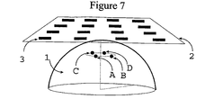
Figure 7 is a cross-sectional view illustrating equivalent positions in relation to the array; - A real aperture synthetically organised radar for breast cancer detection shown in
Figure 1 operates by employing anarray 2 of N antennas (e.g. 3) close to, or in contact with, thebreast 1. Each antenna in turn transmits a pulse and the received signal yi (t) at each of the other antennas is recorded. Thepulse generator 8 and thedetector 9 may be time-shared, by means of a switching matrix 5 as shown inFigure 1 , as may any transmit or receive path amplification (6, 7). - Monostatic operation is unattractive because of the difficulty of near-simultaneous transmission and reception on the same antenna, and, since interchanging transmit and receive antennas would not produce any additional information, the total number of transmissions recorded is N(N -1) /2.
- The recorded data is then synthetically focussed at any point of interest in the volume beneath this antenna array by time-aligning the signals yi (t), using the estimated propagation time Ti from the transmit antenna to the receive antenna via any point of interest in the medium.

- where wi are weighting factors that are applied to compensate for differences in the predicted attenuation between the round-trip paths between transmit and receive antennas via the point of interest, and/or to apply various optimisation criteria. - The returned signal energy associated with this point may then computed by integrating the data over a window corresponding to the transmit pulse width τ:

- Alternative methods of obtaining a scalar quantity V from v(t) include computing the magnitude of a DFT at one or more frequencies or multiplying by the transmitted pulse:

- where x(t) is the transmitted pulse waveform. - This signal processing approach is similar in essence to other time-shift-and-sum beamforming algorithms (see for example S. C. Hagness, A. Taflove, and J. E. Bridges, Two-dimensional FDTD analysis of a pulsed microwave confocal system for breast cancer detection: fixed-focus and antenna-array sensors, IEEE Trans. on Biomed. Eng., vol. 45, pp. 1470-9, Dec. 1998; or E. C. Fear and M. A. Stuchly, Microwave detection of breast cancer, IEEE Trans. Microwave Theory and Tech., vol. 48, pp. 1854-1863, Nov. 2000). However, in utilising all possible transmit/receive combinations in the array, it differs from that described by Hagness et al and Fear et al, and the consequently increased number of observations offers additional opportunities for processing gain and clutter rejection.
- The exploitation of the favourable contrast in dielectric properties between normal tissues and malignant tumour depends on radiating and receiving a sufficiently wideband waveform to achieve high resolution. This requires an antenna that radiates well into the breast over a wide band of frequencies. Conventional antennas are obviously not designed to radiate into human tissue, indeed the close proximity of human tissue usually has a detrimental effect on their operation. Additionally the antenna should be inexpensive to construct, suitable for integration into an array and low profile.
-
Figure 2 shows the stacked patch configuration employed for the breast imaging application. The antenna consists of twostacked patches microstrip line 13 is used to feed the lower patch via aslot 12 in the antenna ground plane. Stacked patches and slot feeds have been employed before in antenna designs, however this particular antenna was specifically designed to radiate into a medium of typically εr= 10 which approximately represents the dielectric properties of the breast tissue. Athin radome 14 of εr= 9.8 covers the antenna. - This design of the stacked patch antenna produced a bandwidth of approximately 72% and a beamwidth of approximately ± 35° in the φ = 0° plane and ± 30° in the φ = 90° plane at 7.0 GHz, calculated in tissue. Over the operating frequency range the antenna design was also found to radiate most energy, as desired, into the breast (with a front-to-back ratio better than 15 dB).
- The chief components of the signals collected at the antenna elements are mutual coupling between the antennas, reflections from skin and the tumour echo. The direct antenna couplings will not significantly interfere with the tumour echo as they occur earlier in time. The large signal artefacts caused by reflections from the skin however pose a significant challenge since they tend to mask the reflections from tumours close to skin, despite the benefits of the radar method described herein. Techniques to mitigate the skin reflections are considered in the following sections.
- An N element flat array will collect N(N-1)/2 distinct signals arising from transmission on one antenna and reception on another. Among these paths, a number of sets of similar paths exist with approximately the same mutual coupling and skin reflections.
- For example, any immediately adjacent pair of antennas within the array will observe similar amplitude and phase delays for the skin reflection. Similarly, as shown in
Figure 3 , any next-neighbour pairing of transmit and receive antennas will observe similar amplitude and phase delays for theskin reflection 20. Thecontribution 21 arising from anytumour 19 will however not be the same. - While
Figure 3 illustrates the principle in the simplified scenario of a linear array adjacent to a flat skin surface, the same concept may be extended to two dimensional arrays that conform to a curved surface, such as the breast (seeFigure 4 ). - This method can be exploited to reduce the skin reflections to a considerable extent.
- The signals from similar paths may be processed by either of two alternative variants, as follows:
- a) minor time-shifting and alignment of the signals (to compensate for experimental tolerances) in producing a representative average signal. This average signal is then used as a calibration signal which is subtracted from each signal in the set of similar paths; or
- b) for each signal in the set of similar paths, identification (by integrating the square difference between the two signals) of a second signal from within this set that most closely resembles the first. This "most similar" signal is then used as a calibration signal which is subtracted from the first; or
- c) find that member of the set of similar paths with the smallest mean squared difference from all the others. This "most representative" signal is then used as a calibration signal which is subtracted from all the others.
- The signals may be divided into segments in the time domain (each segment corresponding to a particular feature of the response, arising from a particular physical feature that results in coupling between the transmit and receiver antennas) and method (a) or (b) may then be applied to each segment at a time.
- After the calibration signals have been subtracted, one of the focussing algorithm described in
section 1 above is applied. The residual skin reflection present in the signals will be mitigated by the processing gain of the focussing algorithm. - An N element array will collect N(N-1)/2 distinct signals arising from transmission on one antenna and reception on another. Considering a point of interest A within the body, as shown in
Figure 7 , the process of time-alignment and scaling in equation (1a) yields a focussed signal v1 (t) corresponding to that point A. - Assume that the elements of the array are disposed around an approximately symmetrical breast in a symmetrical, or approximately-symmetrical, fashion. Then there exist one or more additional point(s) B, C, D with the symmetrically equivalent location to A, relative to the array. The focused signals ν 2 (t), ν 3 (t), ν4 (t) associated with these points would be expected to be very similar, containing, for example, the same components for the skin reflection and mutual coupling. If the elements of the array are disposed in a less symmetrical fashion, then there may be fewer than three additional points with symmetrically equivalent positions.
- A calibration signal may then be generated from this subset of focused signals (ν 1 (t), ν2 (t), ν3 (t), ν 4 (t)) and this may then be subtracted from ν 1 (t). In this way skin reflection and mutual couplings will be much reduced.
- The calibration signal may be formed, for example, by
- a) minor time-shifting and alignment of the focused signals (to compensate for experimental tolerances) in producing a representative average signal. This average signal is then used as a calibration signal which is subtracted from each signal in the set; or
- b) for each member of (ν 1 (t), ν 2 (t), ν 3 (t), ν 4 (t)), identification (by integrating the square difference between the two signals) of a second signal from within this set that most closely resembles the first. This "most similar" signal is then used as a calibration signal which is subtracted from the first; or
- c) finding that member of the set with the smallest mean squared difference from all the others. This "most representative" signal is then used as a calibration signal which is subtracted from all the others.
- d) calculating a weighted average of the subset of focused signals. The contribution to any such weighted average may include only giving weight to those members of the subset which, on consideration of appropriate signal statistics, confirm that they differ little one from the other and hence are representative of the common background and of the artefacts associated therewith. This latter approach is important, for example when one of A, B, C or D corresponds to a tumour location in which case the desired tumour response is not affected since the signal is excluded from the averaging.
- The calibration signal may be subtracted from ν 1 (t) directly and the signal energy associated with this point calculated using e.g. equation (1b) or (1c). Alternatively scalar energy values may first be computed for all of (ν 1 (t), ν 2 (t), ν 3 (t), ν 4 (t)), and the subtraction then performed using these scalar energy values rather than the focused signals themselves.
- Skin reflections and mutual couplings can be considerably reduced by employing
screens 23 inFigure 4 between the antenna elements. Having these screens extend to thebreast 1 will eliminate or significantly reduce the skin echoes 20 but will still allow the tumour echoes 21 to reach the antenna elements. In this implementation thespace 22 created between the screens, the skin and the antenna is filled with a matching liquid with similar electrical properties to healthy breast tissue, such as an emulsion of liquid paraffin and water. - The screens are thin aluminium sheets with a thin layer of radar absorbing material on both sides to reduce multiple bounces and resonance effects. Various radar absorbing materials are available, and suitable products include Emerson & Cuming ECCOSORB FGM-40 (1mm thickness), ECCOSORB BSR (0.25mm, 0.5mm thickness) and ECCOSORB FDS (0.75mm thickness). Alternative absorbing materials could be employed, including water-loaded resins.
- The screens may be attached to the antenna support structure in a number of ways, such as gluing, bolting or welding.
- Although the use of the screens will slightly reduce the half power beamwidths of the antenna elements and hence reduce the number of antenna pairs associated with any given location, the benefits are still significant.
- Computer simulations of the antenna elements and associated set of screens show that a well-behaved and almost frequency-independent radiation pattern is obtained over the operating frequency range from 4.5GHz to 9.5GHz.
- Numerical simulations were conducted to analyse the merits of screens, employing a FDTD model developed for the analysis of breast imaging. The computer simulations and FDTD model are described in detail in R. Nilavalan, J. Leendertz, I. J. Craddock, A. Preece, R. Benjamin Numerical Analysis of Microwave Detection of Breast Tumours Using Synthetic Focussing Techniques , Proceedings of the IEEE AP-S International Symposium and USNCIURSI National Radio Science Meeting, Monterey, California, USA, June 2004.
Table 1 Tumour to skin power ratio Tumour Size Diameter (mm) Without screens (dB) With screens (dB) 2 -47.1 -27.0 3 -40.8 -19.6 4 -32.4 -10.9 5 -29.5 -8.7 - The calculated tumour to skin power ratios are given in Table 1 (the signal from the tumour can be calculated exactly using a background subtraction technique) - these can be seen to yield a 20dB reduction in the power of the skin reflection relative to the signal from the tumour.
- As shown in simplified form by
Figure 5 , skin echoes 20 arise from the three layered structure comprising the matching liquid 22 (with assumed relative permittivity ε1), skin 24 (with assumed relative permittivity ε3) and thebreast tissue 1. The total echo comprises reflections from the two interfaces and the multiple bounces between these interfaces. - Since the skin is an attenuating medium, the largest echo is a result of the single reflection from the upper face of the skin. This echo may be reduced by introducing an Anti-Reflection (AR)
layer 25 next to the skin, as shown inFigure 6 . - By considering just this largest echo, approximate theoretical analysis shows that a minimum reflection is achieved when the relative permittivity ε2 of the AR layer is


- where λ is the free-space wavelength. - This approximate result implies, for lossless media, that d should be a quarter-wavelength in the AR layer and to a reasonable approximation this holds for lossy media as well. More rigorous analysis of the reflection and transmission mechanisms will lead to slightly different choices for d and ε2.
- To validate this approach an experiment was devised using a water- and aluminium-loaded resin-based material for the AR layer. By adjusting the water and aluminium content this layer can be made with parameters that were a reasonable approximation to the desired values. The thickness of the layer was of the order of 3mm (approximately λ/4 at the mid-point frequency of 6GHz).
- The reflectivities of the skin phantom with the antireflection layer, and of a layer of skin phantom alone, were measured in a bath of breast tissue phantom medium using a network analyser.
- Although the properties of the layer were optimised for a single frequency of 6GHz, the antireflection layer yielded a reduction of over 10dB in the reflected signal from the skin across the frequency range 4.5GHz to 7GHz. Even outside of this frequency range the performance was generally better with the AR layer present.
- In practice the patient is envisaged as lying in a prone position and for comfort as well as experimental precision, it is envisaged that the breast will be supported by a gently curved shell, probably created from a rigid moulded resin material. It is apparent from the above results that a shell with antireflection properties would be a particularly appropriate choice.
Claims (17)
- A method of measuring the internal structure of an object (1), the method including the steps of:a) energising a transmitter (3) so as to transmit wave energy onto the object;b) detecting the effect of the object on the passage of the wave energy with a plurality of receivers (3) to generate a plurality of output signals;c) focusing the output signals to generate data associated with a desired point (A) in the object;d) selecting one or more additional points (B, C, D) in the object;e) focusing the output signals to generate additional data each associated with a respective additional point; andf) reducing signal artifacts byi) generating calibration data from the additional data, andii) subtracting the calibration data from the data associated with the desired point,wherein each additional point has a symmetrically equivalent position, in relation to the transmitter and receivers, to the desired point so that the data associated with these points would be expected to be very similar.
- A method according to claim 1 wherein step i) includes selecting data associated with one of the additional points (B, C, D).
- A method according to claim 1 wherein step i) includes calculating an average of the additional data.
- A method according to claim 3 wherein the average is a weighted average.
- A method according to any preceding claim wherein the wave energy contains frequency components spanning a range of frequencies.
- A method according to claim 5 wherein the wave energy contains frequency components spanning a range having a width which is greater than 50% of the centre-frequency.
- A method according to claim 5 or 6 wherein the wave energy contains frequency components spanning a range having a width which is greater than 1 GHz, and preferably greater than 4 GHz.
- Apparatus for measuring the internal structure of an object (1), the apparatus including:a) a transmitter (3) configured to transmit wave energy onto the object,b) a plurality of receivers (3) configured to detect the effect of the object on the passage of the wave energy and generate a plurality of output signals; andc) a processor configured to:i) focus the output signals to generate data associated with a desired point (A) in the object;ii) select one or more additional points (B, C, D) in the object;iii) focus the output signals to generate additional data associated with each additional point; andiv) reduce signal artifacts by(1) generating calibration data from the additional data, and(2) subtracting the calibration data from the data associated with the desired point,wherein each additional point has a symmetrically equivalent position, in relation to the transmitter and receivers, to the desired point so that the data associated with these points would be expected to be very similar.
- A method of measuring the internal structure of an object (1), the method including the steps of:a) energising a transmitter (3) so as to transmit wave energy onto the object, the wave energy containing frequency components spanning a range of frequencies;b) detecting the effect of the object on the passage of the wave energy with a plurality of receivers (3) to generate a plurality of output signals; andc) reducing signal artifacts byi) selecting a subset of output signals, each output signal in the subset corresponding with a receiver which is spaced apart from the transmitter by a similar distance, wherein the number of output signals in the subset is smaller than the total number of output signals generated by the receivers,ii) generating one or more calibration signal from the subset of output signals, the calibration signal(s) containing frequency components spanning a range of frequencies, andiii) subtracting the calibration signal(s) from one or more of the output signals in the subset.
- A method according to claim 9 wherein step ii) includes selecting one of the output signals in the subset.
- A method according to claim 9 wherein step ii) includes calculating an average of the subset of output signals.
- A method according to claim 11 wherein the average is a weighted average.
- A method according to any of claims 9 to 12 wherein the calibration signal contains frequency components spanning a range having a width which is greater than 50% of the centre-frequency.
- A method according to any of claims 9 to 13 wherein the calibration signal contains frequency components spanning a range having a width which is greater than 1 GHz, and preferably greater than 4 GHz.
- Apparatus for measuring the internal structure of an object (1), the apparatus including:a) a transmitter (3) configured to transmit wave energy onto the object, the wave energy containing frequency components spanning a range of frequencies;b) a plurality of receivers (3) configured to detect the effect of the object on the passage of the wave energy and generate a plurality of output signals; andc) a processor configured to reduce signal artifacts by:i) selecting a subset of output signals, each output signal in the subset corresponding with a receiver which is spaced apart from the transmitter by a similar distance, wherein the number of output signals in the subset is smaller than the total number of output signals generated by the receivers,ii) generating one or more calibration signals from the subset of output signals, the calibration signal(s) containing frequency components spanning a range of frequencies, andiii) subtracting the calibration signal(s) from one or more of the output signals in the subset.
- A method according to any of the preceding method claims wherein the object is part of a human or animal body.
- A method according to claim 16 wherein the object (1) is a breast.
Applications Claiming Priority (2)
| Application Number | Priority Date | Filing Date | Title |
|---|---|---|---|
| GBGB0502651.3A GB0502651D0 (en) | 2005-02-09 | 2005-02-09 | Methods and apparatus for measuring the internal structure of an object |
| PCT/GB2006/000303 WO2006085052A2 (en) | 2005-02-09 | 2006-01-30 | Methods and apparatus for measuring the internal structure of an object |
Publications (2)
| Publication Number | Publication Date |
|---|---|
| EP1850743A2 EP1850743A2 (en) | 2007-11-07 |
| EP1850743B1 true EP1850743B1 (en) | 2012-12-05 |
Family
ID=34356021
Family Applications (1)
| Application Number | Title | Priority Date | Filing Date |
|---|---|---|---|
| EP06704227A Not-in-force EP1850743B1 (en) | 2005-02-09 | 2006-01-30 | Methods and apparatus for measuring the internal structure of an object |
Country Status (5)
| Country | Link |
|---|---|
| US (1) | US20080071169A1 (en) |
| EP (1) | EP1850743B1 (en) |
| JP (2) | JP5312802B2 (en) |
| GB (1) | GB0502651D0 (en) |
| WO (1) | WO2006085052A2 (en) |
Cited By (16)
| Publication number | Priority date | Publication date | Assignee | Title |
|---|---|---|---|---|
| US9072495B2 (en) | 2006-10-25 | 2015-07-07 | Maui Imaging, Inc. | Method and apparatus to produce ultrasonic images using multiple apertures |
| US9146313B2 (en) | 2006-09-14 | 2015-09-29 | Maui Imaging, Inc. | Point source transmission and speed-of-sound correction using multi-aperature ultrasound imaging |
| US9192355B2 (en) | 2006-02-06 | 2015-11-24 | Maui Imaging, Inc. | Multiple aperture ultrasound array alignment fixture |
| US9220478B2 (en) | 2010-04-14 | 2015-12-29 | Maui Imaging, Inc. | Concave ultrasound transducers and 3D arrays |
| US9265484B2 (en) | 2011-12-29 | 2016-02-23 | Maui Imaging, Inc. | M-mode ultrasound imaging of arbitrary paths |
| US9282945B2 (en) | 2009-04-14 | 2016-03-15 | Maui Imaging, Inc. | Calibration of ultrasound probes |
| US9339256B2 (en) | 2007-10-01 | 2016-05-17 | Maui Imaging, Inc. | Determining material stiffness using multiple aperture ultrasound |
| US9510806B2 (en) | 2013-03-13 | 2016-12-06 | Maui Imaging, Inc. | Alignment of ultrasound transducer arrays and multiple aperture probe assembly |
| US9572549B2 (en) | 2012-08-10 | 2017-02-21 | Maui Imaging, Inc. | Calibration of multiple aperture ultrasound probes |
| US9582876B2 (en) | 2006-02-06 | 2017-02-28 | Maui Imaging, Inc. | Method and apparatus to visualize the coronary arteries using ultrasound |
| US9668714B2 (en) | 2010-04-14 | 2017-06-06 | Maui Imaging, Inc. | Systems and methods for improving ultrasound image quality by applying weighting factors |
| US9788813B2 (en) | 2010-10-13 | 2017-10-17 | Maui Imaging, Inc. | Multiple aperture probe internal apparatus and cable assemblies |
| US9883848B2 (en) | 2013-09-13 | 2018-02-06 | Maui Imaging, Inc. | Ultrasound imaging using apparent point-source transmit transducer |
| US9986969B2 (en) | 2012-08-21 | 2018-06-05 | Maui Imaging, Inc. | Ultrasound imaging system memory architecture |
| US10226234B2 (en) | 2011-12-01 | 2019-03-12 | Maui Imaging, Inc. | Motion detection using ping-based and multiple aperture doppler ultrasound |
| US10856846B2 (en) | 2016-01-27 | 2020-12-08 | Maui Imaging, Inc. | Ultrasound imaging with sparse array probes |
Families Citing this family (59)
| Publication number | Priority date | Publication date | Assignee | Title |
|---|---|---|---|---|
| PL1989570T3 (en) | 2006-01-17 | 2017-02-28 | Teledyne Australia Pty Ltd. | Surveillance apparatus and method |
| WO2007105963A1 (en) * | 2006-03-10 | 2007-09-20 | Industrial Research Limited | Imaging system |
| EP1935337A1 (en) * | 2006-12-21 | 2008-06-25 | Nederlandse Organisatie voor toegepast- natuurwetenschappelijk onderzoek TNO | An electromagnetic imaging system, a method and a computer program product |
| WO2008134815A1 (en) * | 2007-05-04 | 2008-11-13 | Teledyne Australia Pty Ltd. | Collision avoidance system and method |
| PL2191292T3 (en) * | 2007-09-19 | 2019-09-30 | Teledyne Australia Pty Ltd | Imaging system and method |
| GB0721693D0 (en) * | 2007-11-05 | 2007-12-12 | Univ Bristol | Antenna for investigating structure of human or animal |
| GB0721694D0 (en) | 2007-11-05 | 2007-12-12 | Univ Bristol | Methods and apparatus for measuring the contents of a search volume |
| EP2234539B1 (en) * | 2007-12-28 | 2015-05-20 | Interstitial, LLC | Synthetic aperture radar system |
| US8989837B2 (en) | 2009-12-01 | 2015-03-24 | Kyma Medical Technologies Ltd. | Methods and systems for determining fluid content of tissue |
| WO2011067623A1 (en) * | 2009-12-01 | 2011-06-09 | Kyma Medical Technologies Ltd | Locating features in the heart using radio frequency imaging |
| JP5224454B2 (en) * | 2008-09-19 | 2013-07-03 | 国立大学法人広島大学 | Abnormal tissue detection device |
| SE532807C2 (en) * | 2008-10-30 | 2010-04-13 | Arbexa Ind Ab | Antenna device and microwave imaging device |
| WO2010085846A2 (en) | 2009-01-30 | 2010-08-05 | Teledyne Australia Pty Ltd | Apparatus and method for assisting vertical takeoff vehicles |
| DE102009012109B4 (en) * | 2009-03-06 | 2011-05-12 | Siemens Aktiengesellschaft | Digital method for channel reduction in MR receiving systems and corresponding device |
| DE102009021232B4 (en) * | 2009-05-14 | 2017-04-27 | Siemens Healthcare Gmbh | Patient couch, method for a patient couch and imaging medical device |
| WO2010143691A1 (en) * | 2009-06-10 | 2010-12-16 | 国立大学法人静岡大学 | Diagnosis apparatus |
| EP2756799B1 (en) | 2009-06-26 | 2016-04-20 | Cianna Medical, Inc. | System for localizing markers or tissue structures within a body |
| US9386942B2 (en) | 2009-06-26 | 2016-07-12 | Cianna Medical, Inc. | Apparatus, systems, and methods for localizing markers or tissue structures within a body |
| CN102573622B (en) * | 2009-08-03 | 2016-01-27 | 沙丘医疗设备有限公司 | For the electromagnetic transducer measured experimenter |
| WO2011016034A2 (en) | 2009-08-03 | 2011-02-10 | Dune Medical Devices Ltd. | Surgical tool |
| JP5408617B2 (en) * | 2009-11-24 | 2014-02-05 | 株式会社産学連携機構九州 | Microwave imaging system |
| GB0920839D0 (en) | 2009-11-27 | 2010-01-13 | Univ Bristol | Contrast agents for medical imaging |
| US8498834B2 (en) * | 2010-01-22 | 2013-07-30 | The Boeing Company | Radio frequency energy deposition analysis |
| WO2012011065A1 (en) | 2010-07-21 | 2012-01-26 | Kyma Medical Technologies Ltd. | Implantable radio-frequency sensor |
| CN103281952B (en) | 2010-11-03 | 2015-09-23 | 合理医疗创新有限公司 | Electromagnetic probe and its manufacture method and the system using this kind of Electromagnetic probe |
| JP2013113603A (en) * | 2011-11-25 | 2013-06-10 | Kyushu Univ | Microwave imaging system and imaging processing method |
| US9492099B2 (en) | 2012-03-19 | 2016-11-15 | Advanced Telesensors, Inc. | System and method for facilitating reflectometric detection of physiologic activity |
| JP6198097B2 (en) * | 2012-12-28 | 2017-09-20 | 国立大学法人広島大学 | Abnormal tissue detection device |
| US9713437B2 (en) | 2013-01-26 | 2017-07-25 | Cianna Medical, Inc. | Microwave antenna apparatus, systems, and methods for localizing markers or tissue structures within a body |
| US10660542B2 (en) | 2013-01-26 | 2020-05-26 | Cianna Medical, Inc. | RFID markers and systems and methods for identifying and locating them |
| WO2014141268A1 (en) * | 2013-03-14 | 2014-09-18 | Vayyar Imaging Ltd. | Microwave imaging resilient to background and skin clutter |
| EP2996555B1 (en) | 2013-03-15 | 2020-10-28 | Cianna Medical, Inc. | Microwave antenna apparatus, systems and methods for localizing markers or tissue structures within a body |
| JP6214201B2 (en) * | 2013-05-02 | 2017-10-18 | キヤノン株式会社 | Image acquisition device |
| EP3063832B1 (en) | 2013-10-29 | 2022-07-06 | Zoll Medical Israel Ltd. | Antenna systems and devices and methods of manufacture thereof |
| WO2015118544A1 (en) | 2014-02-05 | 2015-08-13 | Kyma Medical Technologies Ltd. | Systems, apparatuses and methods for determining blood pressure |
| KR102264965B1 (en) | 2014-03-12 | 2021-06-14 | 가부시키가이샤 인테그랄 지오메트리 사이언스 | Scattering tomography method and scattering tomography device |
| AU2015201655B2 (en) * | 2014-04-07 | 2020-01-02 | Xcalibur Mph Switzerland Sa | Electromagnetic receiver tracking and real-time calibration system and method |
| DK3129804T3 (en) * | 2014-04-07 | 2019-08-12 | Levitection Ltd | ELECTROMAGNETIC SEARCH AND IDENTIFICATION, IN NEARFIELD AREAS |
| WO2016028787A1 (en) | 2014-08-18 | 2016-02-25 | Maui Imaging, Inc. | Network-based ultrasound imaging system |
| US11259715B2 (en) | 2014-09-08 | 2022-03-01 | Zoll Medical Israel Ltd. | Monitoring and diagnostics systems and methods |
| JP2015045655A (en) * | 2014-10-27 | 2015-03-12 | キマ メディカル テクノロジーズ リミテッド | Locating features in heart using radio frequency imaging |
| WO2016115175A1 (en) | 2015-01-12 | 2016-07-21 | KYMA Medical Technologies, Inc. | Systems, apparatuses and methods for radio frequency-based attachment sensing |
| US10610326B2 (en) | 2015-06-05 | 2020-04-07 | Cianna Medical, Inc. | Passive tags, and systems and methods for using them |
| US10499832B2 (en) | 2015-06-05 | 2019-12-10 | Cianna Medical, Inc. | Reflector markers and systems and methods for identifying and locating them |
| GB2540995A (en) * | 2015-08-04 | 2017-02-08 | Micrima Ltd | Methods, apparatus and computer-readable medium for assessing fit in a system for measuring the internal structure of an object |
| AU2017226261A1 (en) | 2016-03-03 | 2018-10-04 | Cianna Medical, Inc. | Implantable markers, and systems and methods for using them |
| US10827949B2 (en) | 2016-04-06 | 2020-11-10 | Cianna Medical, Inc. | Reflector markers and systems and methods for identifying and locating them |
| GB201608687D0 (en) | 2016-05-17 | 2016-06-29 | Micrima Ltd | A medical imaging system and method |
| JP6755022B2 (en) * | 2016-09-07 | 2020-09-16 | 国立大学法人広島大学 | Semiconductor switch circuit and abnormal tissue detection device |
| EP3315075B1 (en) * | 2016-10-27 | 2019-07-10 | Micrima Limited | System and method for combined microwave and ultrasound imaging |
| WO2018083492A1 (en) * | 2016-11-04 | 2018-05-11 | Micrima Limited | A breast density meter and method |
| WO2019030746A1 (en) | 2017-08-10 | 2019-02-14 | Zoll Medical Israel Ltd. | Systems, devices and methods for physiological monitoring of patients |
| CN107884629A (en) * | 2017-10-31 | 2018-04-06 | 北京航空航天大学 | A kind of antenna feeder formula tightens field device |
| JP6849980B2 (en) * | 2017-11-27 | 2021-03-31 | 国立大学法人広島大学 | Abnormal tissue detection device |
| FR3077641B1 (en) * | 2018-02-07 | 2020-02-21 | TiHive | TERAHERTZ REFLECTIVE IMAGING SYSTEM |
| JP7105471B2 (en) * | 2018-02-16 | 2022-07-25 | 国立大学法人広島大学 | Abnormal tissue detector |
| US11883150B2 (en) | 2018-09-06 | 2024-01-30 | Cianna Medical, Inc. | Systems for identifying and locating reflectors using orthogonal sequences of reflector switching |
| JP7196730B2 (en) | 2019-03-28 | 2022-12-27 | 株式会社豊田中央研究所 | Hydrocarbon production device and hydrocarbon production method |
| KR102511753B1 (en) * | 2020-11-19 | 2023-03-20 | 지앨에스 주식회사 | Medical diagnostic device |
Family Cites Families (24)
| Publication number | Priority date | Publication date | Assignee | Title |
|---|---|---|---|---|
| US4148039A (en) * | 1977-07-05 | 1979-04-03 | The Boeing Company | Low reflectivity radome |
| FI58719C (en) * | 1979-06-01 | 1981-04-10 | Instrumentarium Oy | DIAGNOSTISERINGSANORDNING FOER BROESTKANCER |
| CA1291220C (en) * | 1985-11-07 | 1991-10-22 | Microwave Medical Systems, Inc. | Multiple antennae breast screening system |
| US4980696A (en) * | 1987-05-12 | 1990-12-25 | Sippican Ocean Systems, Inc. | Radome for enclosing a microwave antenna |
| JPH06180359A (en) * | 1992-12-15 | 1994-06-28 | Japan Radio Co Ltd | Target detecting and processing circuit |
| US5704355A (en) * | 1994-07-01 | 1998-01-06 | Bridges; Jack E. | Non-invasive system for breast cancer detection |
| US5829437A (en) * | 1994-07-01 | 1998-11-03 | Interstitial, Inc. | Microwave method and system to detect and locate cancers in heterogenous tissues |
| US6421550B1 (en) * | 1994-07-01 | 2002-07-16 | Interstitial, L.L.C. | Microwave discrimination between malignant and benign breast tumors |
| US5999836A (en) * | 1995-06-06 | 1999-12-07 | Nelson; Robert S. | Enhanced high resolution breast imaging device and method utilizing non-ionizing radiation of narrow spectral bandwidth |
| GB9611800D0 (en) | 1996-06-06 | 1996-08-07 | Univ Bristol | Post-reception focusing in remote detection systems |
| GB9611801D0 (en) * | 1996-06-06 | 1996-08-07 | Univ Bristol | Apparatus for and method of detecting a reflector with a medium |
| US5949387A (en) * | 1997-04-29 | 1999-09-07 | Trw Inc. | Frequency selective surface (FSS) filter for an antenna |
| JPH11264869A (en) * | 1998-03-18 | 1999-09-28 | Geo Search Kk | Permittivity measuring method and device therefor |
| US6454711B1 (en) * | 1999-04-23 | 2002-09-24 | The Regents Of The University Of California | Microwave hemorrhagic stroke detector |
| US6603312B2 (en) * | 2000-12-11 | 2003-08-05 | Cbg Corporation | Multi-frequency array induction tool |
| JP4709421B2 (en) * | 2001-04-27 | 2011-06-22 | 三井造船株式会社 | Multipath 3D visualization radar system |
| US7570063B2 (en) * | 2001-07-06 | 2009-08-04 | Wisconsin Alumni Research Foundation | Space-time microwave imaging for cancer detection |
| WO2003009753A2 (en) * | 2001-07-26 | 2003-02-06 | Chad Bouton | Detection of fluids in tissue |
| JP2003279649A (en) * | 2002-03-22 | 2003-10-02 | Denso Corp | Radar apparatus |
| US20040077943A1 (en) * | 2002-04-05 | 2004-04-22 | Meaney Paul M. | Systems and methods for 3-D data acquisition for microwave imaging |
| TWI280687B (en) * | 2002-08-09 | 2007-05-01 | Wistron Neweb Corp | Multi-patch antenna which can transmit radio signals with two frequencies |
| US7427967B2 (en) * | 2003-02-01 | 2008-09-23 | Qinetiq Limited | Phased array antenna and inter-element mutual coupling control method |
| US20070293752A1 (en) * | 2004-09-10 | 2007-12-20 | Industrial Research Limited | Synthetic Focusing Method |
| US7809427B2 (en) * | 2005-02-11 | 2010-10-05 | Wisconsin Alumni Research Foundation | Time domain inverse scattering techniques for use in microwave imaging |
-
2005
- 2005-02-09 GB GBGB0502651.3A patent/GB0502651D0/en not_active Ceased
-
2006
- 2006-01-30 EP EP06704227A patent/EP1850743B1/en not_active Not-in-force
- 2006-01-30 WO PCT/GB2006/000303 patent/WO2006085052A2/en active Application Filing
- 2006-01-30 JP JP2007554628A patent/JP5312802B2/en not_active Expired - Fee Related
-
2007
- 2007-08-08 US US11/835,647 patent/US20080071169A1/en not_active Abandoned
-
2012
- 2012-11-05 JP JP2012243592A patent/JP5646574B2/en not_active Expired - Fee Related
Cited By (31)
| Publication number | Priority date | Publication date | Assignee | Title |
|---|---|---|---|---|
| US9192355B2 (en) | 2006-02-06 | 2015-11-24 | Maui Imaging, Inc. | Multiple aperture ultrasound array alignment fixture |
| US9582876B2 (en) | 2006-02-06 | 2017-02-28 | Maui Imaging, Inc. | Method and apparatus to visualize the coronary arteries using ultrasound |
| US9526475B2 (en) | 2006-09-14 | 2016-12-27 | Maui Imaging, Inc. | Point source transmission and speed-of-sound correction using multi-aperture ultrasound imaging |
| US9146313B2 (en) | 2006-09-14 | 2015-09-29 | Maui Imaging, Inc. | Point source transmission and speed-of-sound correction using multi-aperature ultrasound imaging |
| US9986975B2 (en) | 2006-09-14 | 2018-06-05 | Maui Imaging, Inc. | Point source transmission and speed-of-sound correction using multi-aperture ultrasound imaging |
| US9420994B2 (en) | 2006-10-25 | 2016-08-23 | Maui Imaging, Inc. | Method and apparatus to produce ultrasonic images using multiple apertures |
| US10130333B2 (en) | 2006-10-25 | 2018-11-20 | Maui Imaging, Inc. | Method and apparatus to produce ultrasonic images using multiple apertures |
| US9072495B2 (en) | 2006-10-25 | 2015-07-07 | Maui Imaging, Inc. | Method and apparatus to produce ultrasonic images using multiple apertures |
| US9339256B2 (en) | 2007-10-01 | 2016-05-17 | Maui Imaging, Inc. | Determining material stiffness using multiple aperture ultrasound |
| US10675000B2 (en) | 2007-10-01 | 2020-06-09 | Maui Imaging, Inc. | Determining material stiffness using multiple aperture ultrasound |
| US9282945B2 (en) | 2009-04-14 | 2016-03-15 | Maui Imaging, Inc. | Calibration of ultrasound probes |
| US11051791B2 (en) * | 2009-04-14 | 2021-07-06 | Maui Imaging, Inc. | Calibration of ultrasound probes |
| US10206662B2 (en) | 2009-04-14 | 2019-02-19 | Maui Imaging, Inc. | Calibration of ultrasound probes |
| US11172911B2 (en) | 2010-04-14 | 2021-11-16 | Maui Imaging, Inc. | Systems and methods for improving ultrasound image quality by applying weighting factors |
| US10835208B2 (en) | 2010-04-14 | 2020-11-17 | Maui Imaging, Inc. | Concave ultrasound transducers and 3D arrays |
| US9247926B2 (en) | 2010-04-14 | 2016-02-02 | Maui Imaging, Inc. | Concave ultrasound transducers and 3D arrays |
| US9668714B2 (en) | 2010-04-14 | 2017-06-06 | Maui Imaging, Inc. | Systems and methods for improving ultrasound image quality by applying weighting factors |
| US9220478B2 (en) | 2010-04-14 | 2015-12-29 | Maui Imaging, Inc. | Concave ultrasound transducers and 3D arrays |
| US9788813B2 (en) | 2010-10-13 | 2017-10-17 | Maui Imaging, Inc. | Multiple aperture probe internal apparatus and cable assemblies |
| US10226234B2 (en) | 2011-12-01 | 2019-03-12 | Maui Imaging, Inc. | Motion detection using ping-based and multiple aperture doppler ultrasound |
| US10617384B2 (en) | 2011-12-29 | 2020-04-14 | Maui Imaging, Inc. | M-mode ultrasound imaging of arbitrary paths |
| US9265484B2 (en) | 2011-12-29 | 2016-02-23 | Maui Imaging, Inc. | M-mode ultrasound imaging of arbitrary paths |
| US10064605B2 (en) | 2012-08-10 | 2018-09-04 | Maui Imaging, Inc. | Calibration of multiple aperture ultrasound probes |
| US9572549B2 (en) | 2012-08-10 | 2017-02-21 | Maui Imaging, Inc. | Calibration of multiple aperture ultrasound probes |
| US11253233B2 (en) | 2012-08-10 | 2022-02-22 | Maui Imaging, Inc. | Calibration of multiple aperture ultrasound probes |
| US9986969B2 (en) | 2012-08-21 | 2018-06-05 | Maui Imaging, Inc. | Ultrasound imaging system memory architecture |
| US10267913B2 (en) | 2013-03-13 | 2019-04-23 | Maui Imaging, Inc. | Alignment of ultrasound transducer arrays and multiple aperture probe assembly |
| US9510806B2 (en) | 2013-03-13 | 2016-12-06 | Maui Imaging, Inc. | Alignment of ultrasound transducer arrays and multiple aperture probe assembly |
| US10653392B2 (en) | 2013-09-13 | 2020-05-19 | Maui Imaging, Inc. | Ultrasound imaging using apparent point-source transmit transducer |
| US9883848B2 (en) | 2013-09-13 | 2018-02-06 | Maui Imaging, Inc. | Ultrasound imaging using apparent point-source transmit transducer |
| US10856846B2 (en) | 2016-01-27 | 2020-12-08 | Maui Imaging, Inc. | Ultrasound imaging with sparse array probes |
Also Published As
| Publication number | Publication date |
|---|---|
| JP2008530546A (en) | 2008-08-07 |
| JP2013029527A (en) | 2013-02-07 |
| US20080071169A1 (en) | 2008-03-20 |
| JP5646574B2 (en) | 2014-12-24 |
| EP1850743A2 (en) | 2007-11-07 |
| GB0502651D0 (en) | 2005-03-16 |
| JP5312802B2 (en) | 2013-10-09 |
| WO2006085052A3 (en) | 2006-12-14 |
| WO2006085052A2 (en) | 2006-08-17 |
Similar Documents
| Publication | Publication Date | Title |
|---|---|---|
| EP1850743B1 (en) | Methods and apparatus for measuring the internal structure of an object | |
| CA2451404C (en) | Space-time microwave imaging for cancer detection | |
| US7647089B2 (en) | Surface identification using microwave signals for microwave-based detection of cancer | |
| Nilavalan et al. | Wideband microstrip patch antenna design for breast cancer tumour detection | |
| EP2893594B1 (en) | Wideband radar with heterogeneous antenna arrays | |
| US9372256B2 (en) | Wafer scale sensor ultra-wideband array for tissue diagnosis | |
| WO2000064343A1 (en) | Microwave hemorrhagic stroke detector | |
| US11344215B2 (en) | Handheld and portable scanners for millimeter wave mammography and instant mammography imaging | |
| Alani et al. | Miniaturized UWB elliptical patch antenna for skin cancer diagnosis imaging. | |
| Moscato et al. | A mm-Wave 2D ultra-wideband imaging radar for breast cancer detection | |
| Klemm et al. | Evaluation of a hemi-spherical wideband antenna array for breast cancer imaging | |
| Hassan et al. | Basic evaluation of antennas used in microwave imaging for breast cancer detection | |
| Asok et al. | Double ridge conical horn antenna with dielectric loading for microwave imaging of human breast | |
| Haghpanah et al. | Breast cancer detection by time-reversal imaging using ultra-wideband modified circular patch antenna array | |
| Craddock et al. | Development of a hemi-spherical wideband antenna array for breast cancer imaging | |
| Nilavalan et al. | Breast tumour detection using a flat 16 element array | |
| ul Haq et al. | A Multiple Ring Slots Ultra Wide-Band Antenna (MRS-UWB) for Biomedical Applications | |
| Benchakroun et al. | Coverage estimation for microwave imaging using full multistatic radar imaging algorithms with restricted opening | |
| Al Amro et al. | Review of practical antennas for microwave and millimetre-wave medical imaging | |
| Wang et al. | Convex optimization-based design of sparse arrays for 3-D near-field imaging | |
| Parveen et al. | Detection of Blood Clots inside the Brain using Microwave Imaging | |
| Jain | A Feasibility Study for Biomedical Applications via Microwave Imaging | |
| Vijayalakshmi et al. | Design of Compact Ultra‐Wideband (UWB) Antennas for Microwave Imaging Applications | |
| Razzicchia et al. | Metasurface-Enhanced Antenna for Microwave Breast Imaging | |
| Lalitha et al. | Design of UWB antipodal vivaldi antenna with parasitic patch for microwave head imaging system |
Legal Events
| Date | Code | Title | Description |
|---|---|---|---|
| PUAI | Public reference made under article 153(3) epc to a published international application that has entered the european phase |
Free format text: ORIGINAL CODE: 0009012 |
|
| 17P | Request for examination filed |
Effective date: 20070905 |
|
| AK | Designated contracting states |
Kind code of ref document: A2 Designated state(s): AT BE BG CH CY CZ DE DK EE ES FI FR GB GR HU IE IS IT LI LT LU LV MC NL PL PT RO SE SI SK TR |
|
| DAX | Request for extension of the european patent (deleted) | ||
| RAP1 | Party data changed (applicant data changed or rights of an application transferred) |
Owner name: MICRIMA LIMITED |
|
| 17Q | First examination report despatched |
Effective date: 20090417 |
|
| GRAP | Despatch of communication of intention to grant a patent |
Free format text: ORIGINAL CODE: EPIDOSNIGR1 |
|
| RIN1 | Information on inventor provided before grant (corrected) |
Inventor name: LEENDERTZ, JACK ALBERT Inventor name: BENJAMIN, RALPH Inventor name: PREECE, ALAN WILLIAM Inventor name: NILAVALAN, RAJAGOPAL DEPT. OF ELECTRONICS&COMP. Inventor name: WILSON, FREDERICK JOHN 9 SPRATS BARN CRESCENT Inventor name: CRADDOCK, IAN |
|
| GRAS | Grant fee paid |
Free format text: ORIGINAL CODE: EPIDOSNIGR3 |
|
| GRAA | (expected) grant |
Free format text: ORIGINAL CODE: 0009210 |
|
| AK | Designated contracting states |
Kind code of ref document: B1 Designated state(s): AT BE BG CH CY CZ DE DK EE ES FI FR GB GR HU IE IS IT LI LT LU LV MC NL PL PT RO SE SI SK TR |
|
| REG | Reference to a national code |
Ref country code: GB Ref legal event code: FG4D |
|
| REG | Reference to a national code |
Ref country code: CH Ref legal event code: EP |
|
| REG | Reference to a national code |
Ref country code: AT Ref legal event code: REF Ref document number: 586824 Country of ref document: AT Kind code of ref document: T Effective date: 20121215 |
|
| REG | Reference to a national code |
Ref country code: IE Ref legal event code: FG4D |
|
| REG | Reference to a national code |
Ref country code: DE Ref legal event code: R096 Ref document number: 602006033444 Country of ref document: DE Effective date: 20130131 |
|
| REG | Reference to a national code |
Ref country code: AT Ref legal event code: MK05 Ref document number: 586824 Country of ref document: AT Kind code of ref document: T Effective date: 20121205 |
|
| PG25 | Lapsed in a contracting state [announced via postgrant information from national office to epo] |
Ref country code: LT Free format text: LAPSE BECAUSE OF FAILURE TO SUBMIT A TRANSLATION OF THE DESCRIPTION OR TO PAY THE FEE WITHIN THE PRESCRIBED TIME-LIMIT Effective date: 20121205 Ref country code: SE Free format text: LAPSE BECAUSE OF FAILURE TO SUBMIT A TRANSLATION OF THE DESCRIPTION OR TO PAY THE FEE WITHIN THE PRESCRIBED TIME-LIMIT Effective date: 20121205 Ref country code: FI Free format text: LAPSE BECAUSE OF FAILURE TO SUBMIT A TRANSLATION OF THE DESCRIPTION OR TO PAY THE FEE WITHIN THE PRESCRIBED TIME-LIMIT Effective date: 20121205 Ref country code: ES Free format text: LAPSE BECAUSE OF FAILURE TO SUBMIT A TRANSLATION OF THE DESCRIPTION OR TO PAY THE FEE WITHIN THE PRESCRIBED TIME-LIMIT Effective date: 20130316 |
|
| REG | Reference to a national code |
Ref country code: NL Ref legal event code: VDEP Effective date: 20121205 |
|
| REG | Reference to a national code |
Ref country code: LT Ref legal event code: MG4D |
|
| PG25 | Lapsed in a contracting state [announced via postgrant information from national office to epo] |
Ref country code: GR Free format text: LAPSE BECAUSE OF FAILURE TO SUBMIT A TRANSLATION OF THE DESCRIPTION OR TO PAY THE FEE WITHIN THE PRESCRIBED TIME-LIMIT Effective date: 20130306 Ref country code: SI Free format text: LAPSE BECAUSE OF FAILURE TO SUBMIT A TRANSLATION OF THE DESCRIPTION OR TO PAY THE FEE WITHIN THE PRESCRIBED TIME-LIMIT Effective date: 20121205 Ref country code: LV Free format text: LAPSE BECAUSE OF FAILURE TO SUBMIT A TRANSLATION OF THE DESCRIPTION OR TO PAY THE FEE WITHIN THE PRESCRIBED TIME-LIMIT Effective date: 20121205 Ref country code: PL Free format text: LAPSE BECAUSE OF FAILURE TO SUBMIT A TRANSLATION OF THE DESCRIPTION OR TO PAY THE FEE WITHIN THE PRESCRIBED TIME-LIMIT Effective date: 20121205 |
|
| PG25 | Lapsed in a contracting state [announced via postgrant information from national office to epo] |
Ref country code: AT Free format text: LAPSE BECAUSE OF FAILURE TO SUBMIT A TRANSLATION OF THE DESCRIPTION OR TO PAY THE FEE WITHIN THE PRESCRIBED TIME-LIMIT Effective date: 20121205 |
|
| PG25 | Lapsed in a contracting state [announced via postgrant information from national office to epo] |
Ref country code: IS Free format text: LAPSE BECAUSE OF FAILURE TO SUBMIT A TRANSLATION OF THE DESCRIPTION OR TO PAY THE FEE WITHIN THE PRESCRIBED TIME-LIMIT Effective date: 20130405 Ref country code: CZ Free format text: LAPSE BECAUSE OF FAILURE TO SUBMIT A TRANSLATION OF THE DESCRIPTION OR TO PAY THE FEE WITHIN THE PRESCRIBED TIME-LIMIT Effective date: 20121205 Ref country code: EE Free format text: LAPSE BECAUSE OF FAILURE TO SUBMIT A TRANSLATION OF THE DESCRIPTION OR TO PAY THE FEE WITHIN THE PRESCRIBED TIME-LIMIT Effective date: 20121205 Ref country code: BE Free format text: LAPSE BECAUSE OF FAILURE TO SUBMIT A TRANSLATION OF THE DESCRIPTION OR TO PAY THE FEE WITHIN THE PRESCRIBED TIME-LIMIT Effective date: 20121205 Ref country code: BG Free format text: LAPSE BECAUSE OF FAILURE TO SUBMIT A TRANSLATION OF THE DESCRIPTION OR TO PAY THE FEE WITHIN THE PRESCRIBED TIME-LIMIT Effective date: 20130305 Ref country code: SK Free format text: LAPSE BECAUSE OF FAILURE TO SUBMIT A TRANSLATION OF THE DESCRIPTION OR TO PAY THE FEE WITHIN THE PRESCRIBED TIME-LIMIT Effective date: 20121205 |
|
| PG25 | Lapsed in a contracting state [announced via postgrant information from national office to epo] |
Ref country code: RO Free format text: LAPSE BECAUSE OF FAILURE TO SUBMIT A TRANSLATION OF THE DESCRIPTION OR TO PAY THE FEE WITHIN THE PRESCRIBED TIME-LIMIT Effective date: 20121205 Ref country code: PT Free format text: LAPSE BECAUSE OF FAILURE TO SUBMIT A TRANSLATION OF THE DESCRIPTION OR TO PAY THE FEE WITHIN THE PRESCRIBED TIME-LIMIT Effective date: 20130405 Ref country code: MC Free format text: LAPSE BECAUSE OF NON-PAYMENT OF DUE FEES Effective date: 20130131 Ref country code: NL Free format text: LAPSE BECAUSE OF FAILURE TO SUBMIT A TRANSLATION OF THE DESCRIPTION OR TO PAY THE FEE WITHIN THE PRESCRIBED TIME-LIMIT Effective date: 20121205 |
|
| REG | Reference to a national code |
Ref country code: CH Ref legal event code: PL |
|
| PLBE | No opposition filed within time limit |
Free format text: ORIGINAL CODE: 0009261 |
|
| STAA | Information on the status of an ep patent application or granted ep patent |
Free format text: STATUS: NO OPPOSITION FILED WITHIN TIME LIMIT |
|
| REG | Reference to a national code |
Ref country code: IE Ref legal event code: MM4A |
|
| PG25 | Lapsed in a contracting state [announced via postgrant information from national office to epo] |
Ref country code: DK Free format text: LAPSE BECAUSE OF FAILURE TO SUBMIT A TRANSLATION OF THE DESCRIPTION OR TO PAY THE FEE WITHIN THE PRESCRIBED TIME-LIMIT Effective date: 20121205 Ref country code: CH Free format text: LAPSE BECAUSE OF NON-PAYMENT OF DUE FEES Effective date: 20130131 Ref country code: LI Free format text: LAPSE BECAUSE OF NON-PAYMENT OF DUE FEES Effective date: 20130131 |
|
| 26N | No opposition filed |
Effective date: 20130906 |
|
| REG | Reference to a national code |
Ref country code: DE Ref legal event code: R097 Ref document number: 602006033444 Country of ref document: DE Effective date: 20130906 |
|
| PG25 | Lapsed in a contracting state [announced via postgrant information from national office to epo] |
Ref country code: IE Free format text: LAPSE BECAUSE OF NON-PAYMENT OF DUE FEES Effective date: 20130130 |
|
| PG25 | Lapsed in a contracting state [announced via postgrant information from national office to epo] |
Ref country code: CY Free format text: LAPSE BECAUSE OF FAILURE TO SUBMIT A TRANSLATION OF THE DESCRIPTION OR TO PAY THE FEE WITHIN THE PRESCRIBED TIME-LIMIT Effective date: 20121205 Ref country code: TR Free format text: LAPSE BECAUSE OF FAILURE TO SUBMIT A TRANSLATION OF THE DESCRIPTION OR TO PAY THE FEE WITHIN THE PRESCRIBED TIME-LIMIT Effective date: 20121205 |
|
| PG25 | Lapsed in a contracting state [announced via postgrant information from national office to epo] |
Ref country code: LU Free format text: LAPSE BECAUSE OF NON-PAYMENT OF DUE FEES Effective date: 20130130 Ref country code: HU Free format text: LAPSE BECAUSE OF FAILURE TO SUBMIT A TRANSLATION OF THE DESCRIPTION OR TO PAY THE FEE WITHIN THE PRESCRIBED TIME-LIMIT; INVALID AB INITIO Effective date: 20060130 |
|
| REG | Reference to a national code |
Ref country code: FR Ref legal event code: PLFP Year of fee payment: 11 |
|
| REG | Reference to a national code |
Ref country code: FR Ref legal event code: PLFP Year of fee payment: 12 |
|
| REG | Reference to a national code |
Ref country code: FR Ref legal event code: PLFP Year of fee payment: 13 |
|
| PGFP | Annual fee paid to national office [announced via postgrant information from national office to epo] |
Ref country code: DE Payment date: 20210121 Year of fee payment: 16 Ref country code: GB Payment date: 20210121 Year of fee payment: 16 |
|
| PGFP | Annual fee paid to national office [announced via postgrant information from national office to epo] |
Ref country code: IT Payment date: 20220110 Year of fee payment: 17 Ref country code: FR Payment date: 20220110 Year of fee payment: 17 |
|
| REG | Reference to a national code |
Ref country code: DE Ref legal event code: R119 Ref document number: 602006033444 Country of ref document: DE |
|
| GBPC | Gb: european patent ceased through non-payment of renewal fee |
Effective date: 20220130 |
|
| PG25 | Lapsed in a contracting state [announced via postgrant information from national office to epo] |
Ref country code: GB Free format text: LAPSE BECAUSE OF NON-PAYMENT OF DUE FEES Effective date: 20220130 Ref country code: DE Free format text: LAPSE BECAUSE OF NON-PAYMENT OF DUE FEES Effective date: 20220802 |
|
| PG25 | Lapsed in a contracting state [announced via postgrant information from national office to epo] |
Ref country code: FR Free format text: LAPSE BECAUSE OF NON-PAYMENT OF DUE FEES Effective date: 20230131 |
|
| PG25 | Lapsed in a contracting state [announced via postgrant information from national office to epo] |
Ref country code: IT Free format text: LAPSE BECAUSE OF NON-PAYMENT OF DUE FEES Effective date: 20230130 |